CONSTRUCTION OF BRANCH OFFICE-I & CAB,Berhampur CONTRACTOR CHIEF ENGINEER Page1 LIFE INSURANCE CORPORATION OF INDIA EAST CENTRAL ZONAL OFFICE, ENGG. DEPTT. (4 TH FLOOR) “JEEVAN DEEP”, EXHIBITION ROAD, PATNA – 800 001 PHONE: 0612-2501118/2503014, E-mail: [email protected] AN ISO 9001:2015 CERTIFIED DEPARTMENT TECHNICAL SPECIFICATIONS ELECTRICAL WORKS

Welcome message from author
This document is posted to help you gain knowledge. Please leave a comment to let me know what you think about it! Share it to your friends and learn new things together.
Transcript

CONSTRUCTION OF BRANCH OFFICE-I & CAB,Berhampur
CONTRACTOR CHIEF ENGINEER
Pa
ge1
LIFE INSURANCE CORPORATION OF INDIA
EAST CENTRAL ZONAL OFFICE, ENGG. DEPTT. (4TH FLOOR)
“JEEVAN DEEP”, EXHIBITION ROAD, PATNA – 800 001
PHONE: 0612-2501118/2503014,
E-mail: [email protected]
AN ISO 9001:2015 CERTIFIED DEPARTMENT
TECHNICAL SPECIFICATIONS
ELECTRICAL WORKS
CONSTRUCTION OF BRANCH OFFICE-I & CAB,Berhampur
CONTRACTOR CHIEF ENGINEER
Pa
ge2
ELECTRICAL WORKS TECHNICAL SPECIFICATIONS FOR PROPOSED LIC BRANCH
OFFECES AT BERHANPUR(B.O-1 & CAB)
1.0 ELECTRICAL GENERAL PROVISIONS:
1.1 GENERAL
1.1.1 Work Description
The scope of works for all electrical works and system comprises of design,
engineering, supply, delivery, installation, testing and commissioning, handover,
training, maintenance and warranty all as described or reasonably implied in the
Contract. The EPC Contractor is obliged to provide fully functioning works and
systems in conformance with the requirements of the Contract and approved
design and development documents prepared by the EPC contractor.
In the event certain items are not fully described or indicated in the Contract, but
deemed essential by the EPC contractor for the performance of the works and
systems then the provision of such items shall form part of the EPC Contractors
scope of works at no additional cost to the Owner.
The drawings and documents from LICI shall be used as guidance for the EPC
contractor in producing his detail design and shop drawings for carrying out
works at site.
The EPC Contractor shall be responsible to co-ordinate the equipment and
services and shall produce properly co-ordinate shop drawings to demonstrate
the installation comply with the performance requirement with shop drawings,
calculations and details. The LICI shall monitor the process of shop drawings and
document preparation.
Shop drawings shall take into account actual measurement and setting out
dimensions/levels obtained and determined by the EPC Contractor on site, actual
equipment / material used, actual routing of services, co-ordination with all
installation, and site conditions/constraints.
1.1.2 Scope of Work:
HT, LT, and ELV installation shall generally include the following:
Electrical Service Connection: Based on prevailing electricity rules 415/ 230 V supply will
be made available through Individual metering system by the contractor for each occupant and
common services. 11KV supply connection received from the local electricity company is to be
converted to rated LT supply voltage through step down transformer (not less than 250 KVA)
inside the site for which the space has been allocated. All works as required, to get the
connection from Electricity distribution company and its further distribution shall be done
including cabling from 11 KV ESS as the case may be up to the site of work with necessary HT
Panel consisting of VCB and its stepping down to 415 v for distribution by providing step- down
transformers.
Liaisoning with all concerned authorities to obtain electrical service connection for
required load. To coordinate for provision of incoming electricity supply. Scope of work

CONSTRUCTION OF BRANCH OFFICE-I & CAB,Berhampur
CONTRACTOR CHIEF ENGINEER
Pa
ge3
will start from the HT side and converted to LT by providing Sub-station and metering of
branch office.
Complete earthing systems for connection with component electrical systems.
Internal Services: Complete LT distribution system including main LT
switchboard, Automatic power factor correction devices, sub-boards and
distribution boards, and associated distribution main and sub-main cabling/wiring
and associated accessories.
Complete lighting with wiring and power installation including all final circuiting
work and associated accessories.
Normal and emergency lighting supply and installation and associated
accessories.
earthing system.
Complete lightning protection system and associated accessories.
Complete telephone cabling system and associated accessories.
Complete wiring work to external and public area as per lighting design and
associated accessories.
Complete internal cable system and outlets for Telephone and associate works.
Miscellaneous works like providing and fixing of rubber mats, fire buckets, first
aid box, fire extinguishers, etc. at electrical Sub-station/panel room.
All associated interfacing power supply work to other mechanical installations.
Conventional Fire Alarm System and fire Hydrant system.
Voltage drop, power factor and other parameter shall be as per Central electricity
Authority and IGBC requirement.
Lighting density shall be furnished through energy.
All associated interfacing works with other M&E installations.
Other works as shown on the Drawings and described elsewhere in the Contract
documents.
All equipment shall be of the class most suitable for working under the conditions
specified and shall withstand the atmospheric conditions without deterioration.
EPC Contractor shall co-ordinate with all other agencies working at site for
interconnection and safety aspects.
Also the EPC Contractor shall furnish combined guarantee minimum for one year
from the date of successful commissioning of the equipment. In case there is any
defect, the free replacement of any part or in whole will be made immediately at
no extra cost to Owner.
1.1.3 Fee, Permits & Tests:
The EPC contractor shall obtain all sanctions and permits required for the above
said works from all the relevant authorities. On completion of the work, the EPC
Contractor shall obtain N.O.C from concerned authorities. The original of the
same shall be delivered to the Owner/ LICI.

CONSTRUCTION OF BRANCH OFFICE-I & CAB,Berhampur
CONTRACTOR CHIEF ENGINEER
Pa
ge4
The Owner shall have full power regarding the equipments/ materials get tested
by authorized/ recognized independent Contractor/agency at the EPC
contractor’s expense in order to prove their soundness and adequacy. The EPC
contractor will rectify the defects/ suggestions pointed out by independent
Contractor through Owner at EPC contractor’s expense.
The installation shall comply in all respects with the requirements of Indian
Electricity Act 1910, Indian Electricity Rules (IE 1956) and other related Laws and
Regulations (for F.F. etc.) as amended up to date, there under and special
requirements, if any, of the State Electricity Boards etc. The EPC contractor shall
be liable to furnish the list of authorized licensed persons/ employed/ deputed to
carry out the works/ perform the assigned duties to fulfill the requirement of Rule
No.3 of IER 1956 as amended up to date.
1.1.4 Codes & Standards:
The design, manufacture, inspection, testing and performance shall comply with
all the currently applicable standards, safety codes, relevant Bureau of Indian
Standards (BIS), British Standards (BS), International Electro Technical
Commission (IEC) publication, NEMA & VDE Standards amended up to date. The
design engineering, manufacturing and the installation shall be in accordance
with established codes, sound engineering, practices and specifications. Further,
the same shall conform to the statutory regulations applicable in the
country/state.
EPC Contractor shall obtain all approvals from statutory authorities, e.g.
electrical inspector, local Electricity authorities or any other Contractor as
applicable before commissioning of electrical system if required.
In case of any deviation/conflict with the codes & standards, the following order
of precedence shall govern
• Recommended Design guidelines of LICI
• Local codes of practice
• Approved design development documents
1.1.5 Design:
The EPC Contractor shall be fully responsible for the complete design of all works
for the Contract, including all temporary works.
It is the responsibility of the EPC Contractor to ensure that his design does not
compromise the design intents of the LICI’s approved design development
documents, all statutory authorities’ compliances and approvals.
The design and workmanship shall be in accordance with the best engineering
practices, to ensure satisfactory performance and service life. The equipment
offered by the EPC contractor shall be complete in all respects.
Any materials or accessories, which may not have been specifically mentioned,
but which are usual and necessary for the completion of the system and
satisfactory & trouble free operation and maintenance of the equipment shall be
provided without any extra cost to the Owner. This shall also include spares for
commissioning of the equipment.

CONSTRUCTION OF BRANCH OFFICE-I & CAB,Berhampur
CONTRACTOR CHIEF ENGINEER
Pa
ge5
This specification defines the basic guidelines to develop a suitable electrical
system as necessary for the Complex. All data required in this regard shall be
taken in to consideration to develop a detailed engineering for the system. Site
conditions as applicable are mentioned elsewhere.
1.1.6 EPC contractor shall be responsible for:
• Detailed co-ordination with other services, shop drawings for various electrical
layouts such as equipment layout, cabling layouts, earthing layouts, including
equipment installation and cable termination details etc. prior to start of work.
• Preparation of bill of materials for electrical works.
• Protection co-ordination drawings/ tables for complete power system.
• Shop inspection and testing procedures.
• Field-testing and commissioning procedures.
• Preparation of as built drawings.
EPC contractor shall also be responsible for: Any other work/activity
which is not listed above however is necessary for completeness of
electrical system.
1.1.7 Date of Commencement and Completion Period:
The EPC contractor shall be allowed admittance to the site on the date of
commencement as described in the General Conditions and he shall there upon
and forthwith begin the works and shall regularly proceed with and complete the
same on or before the date of completion subject, nevertheless to the provisions
for the extension of time.
The time being the essence of the contract, the EPC Contractor will adhere to the
time, progress chart and project schedule and will give proportional
output/progress in proportional time.
1.1.8 Schedule and Manner of Operations:
Time being the essence of this Contract, the EPC Contractor will be expected to
furnish all labor and materials in sufficient quantities and at appropriate times,
expedite and schedule the work as required and so manage the operation that
the work will be completed within the time stated in the Contract.
1.1.9 Design Conditions:
Shall be as per relevant standard.
1.1.10 Coordination of Work
Contract documents establish scope, materials and quality but are not detailed
installation instruction.
Coordinate work with related trades and furnish, in writing, any information
necessary to permit the work of related trades to be installed satisfactorily and
with the least possible conflict or delay.
The drawings show the general arrangement of equipment and appurtenances.
Follow these drawings as closely as the actual construction and the work of other

CONSTRUCTION OF BRANCH OFFICE-I & CAB,Berhampur
CONTRACTOR CHIEF ENGINEER
Pa
ge6
divisions will permit. Provide off-sets, fittings, and accessories which may be
required but not shown on the drawings. Investigate the site, and review
drawings of other systems/works to determine conditions affecting the work, and
provide such work and accessories as may be required to accommodate such
conditions.
The locations of switches, panels and other equipments indicated on the drawings
are approximately correct. Exercise particular caution with reference to the
location of panels, switches, etc., and have the precise and definite locations
accepted by the Engineer before proceeding with the installation.
The drawings show only the general run of services and approximate location of
equipment, outlets, panels, etc. Any significant changes in location of equipment,
outlets, panels, etc., necessary in order to meet field conditions shall be brought
to the determine attention of the LICI for review before such alterations are
made. Modifications shall be made at no additional cost to the Contract.
Carefully check space requirements with other division works to ensure that
equipment can be installed in the space allotted.
Wherever work interconnects with work amongst different installation, coordinate
with other trades to insure that they have the information necessary so that the
EPC Contractor may properly install the necessary connections and equipment.
Identify items requiring access in order that the Ceiling Trade will know where to
install access doors and panels.
Furnish and set sleeves for passage of risers through structural masonry and
concrete walls and floors and elsewhere as required for the proper protection of
each riser passing through building surfaces.
Provide fire stopping around all pipes, conduits, ducts, sleeves, etc, which pass
through fire compartments.
Provide required supports and hangers for equipment suitably so as not to exceed
allowable loading of structures.
Wherever the work is of sufficient complexity, prepare additional detail drawings
to scale to coordinate the work with the work of other trades. Detailed work shall
be clearly identified on the drawings as to the area to which it applies. Submit
these drawings to the Engineer for review. At completion include a set of these
drawings with each set of record drawings.
Coordinate with the local utility companies/authorities for their requirements for
service connections and provide all necessary provisions, grounding, materials,
equipment, labor, testing, and appurtenances.
Before commencing works, examine adjoining works on which this work is in any
way affected and report conditions which prevent performance of the works.
Become thoroughly familiar with actual existing conditions to which connections
must be made or which must be changed or altered.
The EPC Contractor is responsible to any modifications required due to
service not properly coordinated.
1.1.11 Electrical Power Supply Interfaces
CONSTRUCTION OF BRANCH OFFICE-I & CAB,Berhampur
CONTRACTOR CHIEF ENGINEER
Pa
ge7
The EPC Contractor shall provide power by providing transformer and electrical
panel for supply points/isolators at certain designated locations within the Project
for all mechanical and electrical installations. It is the responsibility of the
Contractor to coordinate and make connections to these power supply
points/isolators and to provide all the necessary ‘down-stream’ power supply
distribution board/network to the mechanical system’s control panels, equipment,
sensors, field devices, etc.
1.1.12 Interfacing With All Services and Systems
General
• For every control panel and each module of the switchgears, spare terminals
shall be provided for future interfacing works.
• Wiring and cables for interfacing with the fire alarm system and other fire
protection and life safety systems shall be fire rated to comply with Civil
Defense’s requirements.
1.1.13 Examination of Site
Prior to the submitting of bids, visit the project site and become familiar with all
conditions affecting the proposed installation and make provisions as to the cost
thereof.
The Contract Documents do not make representations regarding the character or
extent of the sub-soils, water levels, existing structural, mechanical and electrical
installations, above or below ground, or other sub-surface conditions which may
be encountered during the work, based on examination of the site or other
information. Failure to examine the drawings or other information does not
relieve the EPC Contractor of responsibility for satisfactorily completion of the
work.
1.1.14 Excavation and Backfill
Where ever required provide trenches details, duly approved by the LICI with all
relevant section etc. as per IS codes, minimum before 1 month of laying the
pipes, etc. Co ordinate with during the excavation, and ensure that the
excavation and backfilling is being properly done as per requirement.
Where ever it is asked by the Owner/ LICI for providing trenches in EPC
Contractor’s scope. It is deemed that the cost of the pipe is inclusive of trench
digging and backfilling. The following points needs to be taken care of while
making the trenches.
The trench shall be of widths necessary for the proper execution of the work.
Grade bottom of the trenches accurately to provide uniform bearing and support
the work on undisturbed soil at every point along its entire length. Except where
rock is encountered, do not excavate below the depths indicated. Where rock
excavations are required, excavate rock to a minimum over depth of four inches
below the trench depths indicated on the drawings or required. Backfill over
depths in the rock excavation and unauthorized over depths with loose, granular,
moist earth, thoroughly machine tamped to a compaction level of at least 95% to
standard proctor density or 75% relative density or as specified by the Engineer.
Wherever unstable soil that is incapable of properly supportingthe work is

CONSTRUCTION OF BRANCH OFFICE-I & CAB,Berhampur
CONTRACTOR CHIEF ENGINEER
Pa
ge8
encountered in the bottom of the trench, remove soil to a depth required
andbackfill the trench to the proper grade with coarse sand, fine gravel or other
suitable material. Excavate trenches for utilities that will provide the following
minimum depths of cover from existing grade or from indicated finished grade as
required by local authorities. Trenches should not be placed within 3 meters of
foundation or soil surfaces which must be resist horizontal forces.
Do not backfill until all required tests have been performed and installation
observed by the Engineer. Comply with the requirements of other sections of the
specifications. Backfill shall consist of non-expansive soil with limited porosity.
Deposit in 15 cm layers and thoroughly and carefully tamp until the work has a
cover of not less than 30 cm. Backfill and tamp remainder of trench at 30 cm
intervals until complete. Uniformly grade the finished surface.
1.1.15 Cutting and Patching
All kinds of cutting and repairing of brick Walls or Partitions, etc. for the proper
routing of pipe, cutting and repairing of RCC wall, or ceiling shall be in the scope
of the EPC contractor. Where cutting, channeling, chasing or drilling of floors,
walls, partitions, ceilings or other surfaces is necessary for the proper installation,
support or anchorage of conduit or other equipment, layout the work carefully in
advance. Repair any damage to the building, piping, equipment or defaced finish
plaster, woodwork, metalwork, etc., using skilled trade people of the trades
required at no additional cost to the Contract. Provide slots, chases, openings and
recesses through floors, walls, ceilings, and roofs as required. Where these
openings are not provided, provide cutting and patching to accommodate
penetrations at no additional cost to the Contract.
1.1.16 Sealing of Penetrations
Holes in Roof
Roof penetrations for passage of conduits or circular PVC and PVC Cables shall
be sealed watertight using a flexible polypropylene conical sleeve
manufacturer to seal the cable to the roof structure, regardless of the roof
profile. All sharp metal edges, which may come in contact with the cable, shall
be suitably bushed.
Fire Rated Penetrations
Where services penetrate any fire rated barrier, the EPC Contractor shall seal
the penetration with the use of an appropriate material to ensure the integrity
of the fire barrier. The EPC Contractor shall seal the cable enclosures through
fire rated barriers to ensure the integrity and rating of the fire barrier.
1.1.17 Mounting Heights
Verify exact locations and mounting heights with the Engineer before installation.
1.1.18 Supports
Support work in accordance with the best industry practice. Provide supports,
hangers, auxiliary structural members and supplemental hardware required for
support of the work.

CONSTRUCTION OF BRANCH OFFICE-I & CAB,Berhampur
CONTRACTOR CHIEF ENGINEER
Pa
ge9
Provide supporting frames or racks extending from floor slab to ceiling slab for
work indicated as being supported from walls where the walls are incapable of
supporting the weight. In particular, provide such frames or racks in electric
closets and equipment room. Provide supporting frames or racks for equipment
which is installed in a free standing position.
Supporting frames or racks shall be of standard angle, standard channel or
specialty support system steel members, rigidly bolted or welded together and
adequately braced to form a substantial structure. Racks shall be of ample size to
assure a workman like arrangement of all equipment mounted on them. Adequate
support of equipment (including outlet, pull and junction boxes and fittings) shall
not depend on ducts, pipe, electric conduits, raceways, or cables for support.
Equipment shall not rest on or depend for support on suspended ceiling media
(tiles, lath, plaster, as well as splinters, runners, bars and the like in the plane of
the ceiling). Provide independent support of equipment. Do not attach to supports
provided for ductwork, piping or work of other trades.
Provide required supports and hangers for equipment so that loading will not
exceed allowable loading of structure. Equipment and supports shall not come in
contact with work of other trades.
1.1.19 Fastenings
Fasten equipment to building in accordance with the best industry practice.
Where weight applied to the attachment points is 45kg or less, conform to the
following as a minimum:
1. Wood : Wood screws
2. Concrete and solid masonry : Dash Fastener of appropriate ratings -
HILTI/FISHER
3. Solid metal : Machine screws in tapped holes or with
welded studs
Where weight applied to the building attachment point exceeds 45 kg, but is 135
kg or less, conform to the following as a minimum:
• At concrete slabs provide 60cm x 60cm x 13cm steel fishplates on top with
through bolts. Fishplate assemblies shall be chased in and grouted flush
with the top slabs screed line, where no fill is to be applied.
• At steel decking or sub-floor for all fastenings, provide through bolts and
threaded rods. The tops of bolts and rods shall be set at least one inch
below the top fill screed line and grouted in. Suitable washers shall be
used under bolt heads or nuts. In cases where the decking or sub-floor
manufacturer produces specialty hangers to work with his decking or sub-
floor such hangers shall be provided.
Where weight applied to building attachment points exceeds 135 kg, coordinate
with and obtain the approval of LICI and conform to the following as a minimum:
• Provide suitable auxiliary channel or angle iron bridging between building
structural steel elements to establish fastening points. Bridging members

CONSTRUCTION OF BRANCH OFFICE-I & CAB,Berhampur
CONTRACTOR CHIEF ENGINEER
Pa
ge1
0
shall suitably weld or clamped to building steel. Provide threaded rods or
bolts to attach to bridging members.
For items which are shown as being ceiling mounted at locations where fastening
to the building construction element above is not possible, provide suitable
auxiliary channel or angle iron bridging tying to the building structural elements.
Wall mounted equipment may be directly secured to wall by means of steel bolts.
Groups or arrays of equipment may be mounted on adequately sized steel angles,
channels, or bars.
1.1.20 Identification
Identify equipment with permanently attached black phenolic name plates with
13 mm high white engraved lettering. Identification shall include equipment name
or load served as appropriate. Name plates shall be attached with cadmium
plated screws; peel and stick tape or glue on type name plates is unacceptable.
Services runs shall be properly identified as per the requirements in the Contract.
See individual section for additional identification requirements.
1.1.21 Prohibited Labels and Identifications
In all public areas, tenant areas, and similar locations within the project, the
inclusion or installation of any equipment or assembly which bears on any surface
any name, trademark, or other insignia which is intended to identify the
manufacturer, the vendor or other source(s) from which such object has been
obtained is prohibited. Required test lab certification labels shall neither be
removed nor shall identification specifically required under the various technical
sections of the Specifications be removed.
1.1.22 Equipment Pads and Anchor Bolts
Provide all details with proper sections for the equipment pads and anchor. The
equipment pads casting and making provision for anchor fastening shall be as per
the final UNALTERED drawing duly approved by the LICI , shall be in the scope of
EPC contractor.
All equipment pads for all vibrating equipments shall have cork vibration pads
sandwiched between the finish surface and the bottom surface of required
thickness suggested by the EPC contractor to ensure that the minimum vibration
can travel below.
Provide galvanized anchor bolts for all equipment placed on concrete equipment
pads, inertia blocks, or on concrete slabs. Provide bolts of the size and number
recommended by the manufacturer of the equipment and locate by means of
suitable templates. Equipment installed on vibration isolators shall be secured to
the isolator. Secure the isolator to the floor, pad, or support as recommended by
the vibration isolation manufacturer.
Where equipment is mounted on gypsum board partitions, the mounting screws
shall pass through the gypsum board and securely attach to the partition studs.
As an attached to 15 cm square, galvanized metal back plates which are attached
to the gypsum board with an approved non-flammable adhesive. Toggle bolts
installed in gypsum board partitions are not acceptable.

CONSTRUCTION OF BRANCH OFFICE-I & CAB,Berhampur
CONTRACTOR CHIEF ENGINEER
Pa
ge1
1
1.1.23 Miscellaneous:
A site order book will be maintained at site, which will be in the custody of the
Owner, or his representative and all instructions given to the EPC contractor will
be recorded in the site order book and the same has to be signed by the EPC
contractor to comply with the instructions given therein.
After completion of the work the whole installation shall be tested by the EPC
contractor. The tests shall comply the following I.E.E. Regulations and shall be
submitted along with the final bill:
• The result of the insulation test shall comply with the I.E.E. Regulations 1101
to 1108A and 1008B as may be applicable.
• Test shall be carried out to ascertain that all the non-linked SP switches have
been connected to the phase conductor.
• The continuity test of the earthing system shall comply with I.E.E. Regulations
1108 to 1109 to the latest addition.
If the result of the above tests does not comply with the I.E.E. Regulations, the
EPC contractor shall be bound to rectify the faults so that the required results are
obtained.
The EPC contractor shall be responsible to provide all the necessary test
certificates of testing instruments, such as megger insulation tester, earth tester
multi-meter, AVO meter etc for carrying out the above tests. The work will not be
considered as complete and taken over by the Owner till all the components of
the work after being completed at site in all respects have been inspected /
tested by the LICI/Owner to his entire satisfaction and a completion certificate
issued by the Owner/LICI to this effect.
Shop drawing for electrical work e.g. equipment, cable earthing and conduit
layout for all systems shall be prepared by the contractor and got approved
before starting of the work. At the completion of the work and before issuance of
certificate of virtual completion, the EPC contractor shall submit 6 sets of drawing
and two tracing of each drawing to Owner of each layout drawings drawn at
approved.
EPC Contractor’s Superintendence:
• The contractor shall provide all necessary superintendence during the
execution of the works and as long as there is necessity. The contractor or his
competent and authorized agent or representative approved of in writing by
the owner (which approval may at any time be withdrawn) is to be constantly
on the works and shall give his whole time to the superintendence of the
same. Such authorized agent or representative shall receive on behalf of the
contractor, directions and instructions from the Engineer-in-charge or his
representative.
• The contractor shall provide detailed organization of the execution team
deployed for the works with names and CV’s, of all key staff before the
commencement of work and get it approved of in writing by the Owner/ LICI .
Contact telephone or pager numbers for emergency and/or twenty-four (24)
hour call shall also be included.

CONSTRUCTION OF BRANCH OFFICE-I & CAB,Berhampur
CONTRACTOR CHIEF ENGINEER
Pa
ge1
2
• If in any case of withdrawal of any worker/ technician/ Engineer from the
execution team, the replacement of the same shall be done with equivalent
qualification, and shall be approved in writing by the Owner/ LICI .
1.2 PRODUCT, TESTING & COMMISIONING
1.2.1 Design Criteria
Electrical Details for Incoming Supply:
Supply Voltage: 11 KV/415 V
Voltage Regulations: + 10%
Frequency Regulations: + 3%
Combined Regulations: + 10%
Frequency: 50 Hz
Neutral: Grounded
Short Circuit Fault withstand capacity: as per calculations
LT Power Distribution System:
Voltage: 415 V
Frequency: 50 Hz
Neutral: Grounded
Short Circuit Fault withstand capacity: 10kA to 65kA for 1Sec., as per calculations
Painting of Panels:
Powder coating of approved shade as per Specification. (Refer clause of painting)
Painting of Cable Trays and Structural steel:
Powder coating of approved shade as per Specification. (Refer clause of painting)
Cable Details:
LT Control Cables: Copper conductor armoured PVC insulated 1.1 KV grade.
LT Power Cables: Aluminum conductor armoured XLPE insulated.
Grounding Conductors: Copper/ G.I. as per specifications
1.2.2 Drawings/ Specifications
The EPC contractor of his responsibility to carry out the work as per the approved
Drawings / specifications. Additional information required by the bidder for
successfully completing the work shall be obtained by him.
1.2.3 Shop Drawings
The EPC contractor shall prepare detailed coordinated electrical shop drawing
indicating Panel layout, with other relevant services. The shop drawings shall
indicate all setting out details and physical dimensions of all components with
wiring and cable details including system operating write up in the system i.e.
Control and Relay Panel and fixing details for the above mentioned work. All work
shall be carried out on the approval of these drawings. However, approval of
CONSTRUCTION OF BRANCH OFFICE-I & CAB,Berhampur
CONTRACTOR CHIEF ENGINEER
Pa
ge1
3
these drawings do not relieve the contractor of his responsibility for providing
maintenance free and full proof system including any missing
component/accessories to meet with the intent of the specifications. Contractor
will submit 2 (two) prints for preliminary approval and finally 6 (six) prints for
distribution.
1.2.4 Manufacturer’s Instructions
Where manufacturers have furnished specific instructions, relating to the
material/equipments to be used on this job, covering points not specifically
mentioned in this document, manufacturer’s instructions should be followed.
1.2.5 Completion Documents and Drawings
Three copies of operation manuals/catalogues of all standard equipment are to be
furnished by the contractor immediately after commissioning of plant. Three
copies of write up on preventive maintenance, trouble shooting and operating
instructions of the system along with as-built drawings are to be supplied by the
Contractor at the time of commissioning. On completion of the work in all
respects, the Contractor shall supply five portfolios (300x450 mm), each
containing complete set of drawings on approved scale, clearly indicating
complete layouts, location; wiring and sequencing of automatic controls, location
of all concealed wiring and other services. Each portfolio shall also contain
consolidated control diagrams and technical literature on all controls. The
Contractor shall frame under glass, in the Panel rooms, one set of these
consolidated control diagrams.
1.2.6 Materials and Equipment
All the materials and equipments shall be of the approved make and design.
Unless otherwise called from LICI, only the best quality materials and equipment
shall be used.
Fungi static Varnish:
Special moisture and fungus resistant varnish shall be applied on parts, which
may be subjected or predisposed to the formation of fungi due to the presence or
deposit of nutrient substances. The varnish shall not be applied to any surface of
part where the treatment will interfere with the operation or performance of the
equipment. Such surfaces or parts shall be protected against the application of
the varnish.
Ventilation Opening:
In order to ensure adequate ventilation, compartments shall have ventilation
openings provided with fine wire mesh of brass to prevent the entry of insects
and to reduce to a minimum the entry of dirt and dust. Outdoor compartment
openings shall be provided with shutter type blinds.
Degree of Protection:
The enclosures of the control cabinet, junction boxes and marshalling boxes,
panels etc to be installed shall provide degree of protection as detailed here
under.
1. Installed Outdoor : IP-55
CONSTRUCTION OF BRANCH OFFICE-I & CAB,Berhampur
CONTRACTOR CHIEF ENGINEER
Pa
ge1
4
2. Installed indoor in air-conditioned area : IP-31
3. Installed in covered area : IP-42
4. Installed indoor in non air-conditioned
area where possibility of entry of water
is limited : IP-41
5. For LT Switchgear
(AC and DC distribution boards) : IP-42
The degree of protection shall be in accordance with IS: 13947 (Part-I) IEC-947
(Part-I). Type test report for degree of protection test, on each type of the box
shall be submitted for approval.
Rating plates, Name plates and Labels:
LT panel and auxiliary items installed in the building is to permanently attach to it
in a conspicuous position. A rating plate of non-corrosive material with engraved
manufacturer’s name, year of manufacture, equipment name, type or serial
number together with details of loading conditions of equipment in question has
been designed to operate and such diagram plates as may require by the owner.
The rating plate of each equipment shall be in accordance with IEC requirement.
All such name plates, instruction plates, rating plates shall be bilingual with Hindi
inscription first followed by English. Alternatively two separate plates on with
Hindi and another with English inscriptions may be provided.
Quality Assurance Programme:
To ensure that the equipment and services under the scope of this Contract
whether manufactured or performed within the Contractor’s works or at the
Owner’s site or at any other place of work are in accordance with the
specifications, the Contractor shall adopt suitable quality assurance program to
control such activities at all points necessary. Such programme shall be outlined
by the Contractor and shall be finally accepted by the Owner after discussions
before the award of Contract. A quality assurance programme of the contractor
shall generally cover the following:
• His organization structure for the management and implementation of the
proposed quality assurance programme.
• Qualification data for bidder’s key personnel.
• The procedure for purchases of materials, parts components and selection of
services including vendor analysis, source inspection, incoming raw material
inspection, verification of material purchases etc.
• System for shop manufacturing and site erection controls including process
controls and fabrication and assembly control.
• Control of non-conforming items and system for corrective actions.
• Inspection and test procedure both for manufacture and field activities.
• Control of calibration and testing of measuring instruments and field activities.
CONSTRUCTION OF BRANCH OFFICE-I & CAB,Berhampur
CONTRACTOR CHIEF ENGINEER
Pa
ge1
5
• System for indication and appraisal of inspection status.
• System for authorizing release of manufactured product to the Owner.
• System for maintenance of records.
• System for handling storage and delivery.
The Owner or his duly authorized representative reserves the right to carry out
quality audit and quality surveillance of the system and procedure of the
Contractor / his Vendor’s quality management and control activities.
Quality Assurance Documents
The Contractor shall be required to submit the following Quality Assurance
Documents within three weeks after dispatch of the equipment.
• All Non-Destructive Examination procedures, stress relief and weld repair
procedure actually used during fabrication and reports including radiography
interpretation reports.
• Raw material test reports on components as specified by the specification and
/ or agreed to in the quality plan.
• Factory test results for testing required as per applicable codes/mutually
agreed quality plan/standards referred in the technical specification.
• The quality plan with verification of various customer inspection points (CIP)
as mutually and methods used to verify the inspection and testing points in
the quality plan were performed satisfactory.
1.2.7 Inspection, Testing and Inspection Certificates
The Owner and the LICI or duly authorized representative shall have at all
reasonable times free access to the EPC Contractor’s premises or works and shall
have the power at all reasonable times to inspect and examine the materials and
workmanship of the works during its manufacture or erection, if part of the works
is being manufactured or assembled at other premises or works, the EPC
Contractor shall obtain permission to inspect as if the works were manufactured
or assembled on the EPC Contractor’s own premises or works. Inspection may be
made at any stage of manufacture, dispatch or at site at the option of the Owner
and the equipment if found unsatisfactory due to bad workmanship or quality,
material is liable to be rejected.
All equipment being supplied shall conform to type tests and shall be subject to
routine tests in accordance with requirements stipulated under respective
sections. Bidder shall submit the type tests reports for approval. The EPC
Contractor shall intimate the Owner/LICI the detailed programme about the tests
at least three (3) weeks in advance in case of domestic supplies. If for any item
type test were pending payment would be made on successful completion of
type/routine test(s) actually carried out as per LICI/Owner instructions.
The EPC Contractor shall give the LICI/Owner thirty (30) days written notice of
any material being ready for testing. Such tests shall be to the EPC Contractor’s
account. The LICI /Owner unless witnessing of the tests is virtually waived will

CONSTRUCTION OF BRANCH OFFICE-I & CAB,Berhampur
CONTRACTOR CHIEF ENGINEER
Pa
ge1
6
attend such tests within thirty (30) days of the date of which the equipment is
notified as being ready for test/inspection, failing which the Contractor may
proceed with the test which shall be deemed to have been made in the presence
of Owner/ LICI and he shall forthwith forward to the LICI duly certified copies of
tests in triplicate.
The LICI/Owner within fifteen (15) days from the date of inspection as defined
shall inform in writing to the Contractor of any objection to any drawings and all
or any equipment and workmanship which in his opinion is not in accordance with
the Contract. The Contractor shall give due consideration to such objections and
make the necessary modifications accordingly.
When the factory tests have been completed at the Contractor’s or Sub-
contractor’s works, the LICI/Owner shall issue a certificate to this effect within
fifteen (15) days after completion of tests but if the tests are not witnessed by
the LICI/Owner, the certificate shall be issued within fifteen (15) days of receipt
of the Contractor’s Test certificate by the LICI/Owner. Failure of the issue such a
certificate shall not prevent the Contractor from proceeding with the works. The
completion of these tests or the issue of the certificate shall not bind the Owner
to accept the equipment should, it, on further tests after erection, is found not to
comply with the Specification. The equipment shall be dispatched to site only
after approval of test reports and issuance of material inspection clearance
certificate by the Owner.
For tests whether at the premises or at the works of the Contractor or of any
Sub-Contractor, the Contractor except where otherwise specified shall provide
free of charge such items as labor, materials, electricity, fuel, water, stores,
apparatus and instruments as may be required by Owner/LICI or this authorized
representative to carry out effectively such tests of the equipment in accordance
with the Specification.
The inspection by Owner/LICI and issue of Inspection Certificate thereon shall in
no way limit the liabilities and responsibilities of the Contractor in respect of the
agreed quality assurance programme forming a part of the Contract.
The LICI/Owner will have the right of having at his own expenses any other
tests(s) of reasonable nature carried out at Contractor’s premises or at site or in
any other place in addition of aforesaid type and routine tests to satisfy that the
material comply with the specifications.
The Owner/LICI reserves the right for getting any field tests not specified in
respective sections of the technical specification conducted on the completely
assembled equipment at site. The testing equipments for these tests shall be
provided by the Contractor.
1.2.8 Tests
Charging (Pre-commissioning tests):
On completion of erection of the equipment and before charging, each item of the
equipment shall be thoroughly cleaned and then inspected jointly by the
Owner/LICI and the Contractor for correctness and completeness of installation
and acceptability for charging, leading to initial pre-commissioning tests at Site.
The pre- commissioning tests to be performed as per relevant I.S. / vendor/

CONSTRUCTION OF BRANCH OFFICE-I & CAB,Berhampur
CONTRACTOR CHIEF ENGINEER
Pa
ge1
7
bidder submittal and as included in the Contractor’s quality assurance
programme.
Commissioning Tests:
• The available instrumentation and control equipment will be used during such
tests and the Contractor will calibrate all such measuring equipment and
devices as far as practicable. However, immeasurable parameters shall be
taken into account in a reasonable manner by the Contractor for the
requirement of these tests. T
• The tests will be conducted at the specified load points and as near the
specified cycle condition as practicable. The Contractor will apply proper
corrections in calculation, to take into account conditions which do not
correspond to the specified conditions.
• All instruments, tools and tackles required for the successful completion of
the Commissioning Tests shall be provided by the Contractor, free of cost.
• Pre-commissioning test shall be carried out as per relevant IS and/or as
specified in the relevant clause.
• The Contractor shall be responsible for obtaining statutory clearances from
the concerned authorities for commissioning of the equipment. However
necessary fee shall be reimburse by Owner on production of requisite
documents.
1.2.9 Packaging
All the equipments shall be suitably protected, coated, covered or boxed and
crated to prevent damage or deterioration during transit, handling and storage at
Site till the time of erection. While packing all the materials, the limitation from
the point of view of availability of Railway wagon/truck/trailer sizes in India
should be taken account of the Contractor shall be responsible for any loss or
damage during transportation, handling and storage due to improper packing.
Any demurrage, wharfage and other such charges claimed by the transporters,
railways etc. shall be to the account of the Contractor. Owner takes no
responsibility of the availability of any special packaging/transporting
arrangement.
1.2.10 Protection
All coated surfaces shall be protected against abrasion, impact, discoloration and
any other damages. All exposed threaded portions shall be suitably protected
with either a metallic or a non-metallic protecting device. All ends of all valves
and piping and conduit equipment connections shall be properly sealed with
suitable devices to protect them from damage. The parts which are likely to get
rusted, due to exposure to weather should also be properly treated and
protected in a suitable manner.
1.2.11 Finishing Of Metal Surfaces
General:
All metal surfaces shall be subjected to treatment for anti-corrosion protection.
All ferrous surfaces for external use unless otherwise stated elsewhere in the

CONSTRUCTION OF BRANCH OFFICE-I & CAB,Berhampur
CONTRACTOR CHIEF ENGINEER
Pa
ge1
8
specification or specifically agreed, shall be hot-dip galvanized after fabrication.
High tensile steel nuts and bolts and spring washers shall be electro galvanize.
All steel conductors used for earthing/grounding (above ground level) shall be
galvanized according to IS: 2629.
Painting:
• All sheet steel work shall be degreased, pickled, and phosphated in
accordance with the IS-6005 “Code of practice for Phosphate iron and sheet”.
All surfaces, which will not be easily accessible after shop assembly, shall
beforehand be treated and protected for the life of the equipment. The
surfaces, which are to be finished painted after installation or require
corrosion protection until installation, shall be shop painted with at least two
coats of primer. Oil, grease, dirt and swab shall be thoroughly removed by
emulsion cleaning. Rust and scale shall be removed by pickling with dilute
acid followed by washing with running water, rinsing with slightly alkaline hot
water and drying.
• After Phosphate process thorough rinsing shall be carried out with clean
water followed by final rinsing with dilute dichromate solution and oven
drying. The phosphate coating shall be sealed with application of two coats of
ready mixed, stowing type zinc chromate primer. The first coat may be
“flashing dried” while the second coat shall be stoved.
• Powder coating/electrostatic painting of approved shade shall be applied.
• The exterior color of the paint shall be as per IS-5 or as approved by LICI . A
small quantity of finishing paint shall be supplied for minor touching up
required at site after installation of the equipments, if required.
• In case the Bidder proposes to follow his own standard surface finish and
protection procedures or any other established painting procedures like
electrostatic painting etc. the procedure shall be submitted along with the
Bids for Owner’s review and approval.
1.2.12 Handling, Storage and Installation
In accordance with the specific installation instructions as shown on
manufacturer’s drawings or as directed by the Owner or his representative, the
Contractor shall unload, store, erect, install, wire, test and place into commercial
use all the equipment included in the contract. Equipment shall be installed in a
neat, workmanlike manner so that it is level plumb, square and properly aligned
and oriented.
Contractor shall follow the site procedure for transporting of materials,
unloading, and safe storage. The equipments after collection from store shall be
erected, tested and commissioned as per contract specification, manufacturer
guidelines and Engineer-in-charge instruction.
In case of any doubt/misunderstanding as to the correct interpretation of
manufacturer’s drawings or instructions, necessary clarifications shall be obtained
from the Owner/LICI . Contractor shall be held responsible for any damage to the
equipment consequent for not following manufacturer’s drawings/instructions
correctly.

CONSTRUCTION OF BRANCH OFFICE-I & CAB,Berhampur
CONTRACTOR CHIEF ENGINEER
Pa
ge1
9
Where assemblies are supplied in more than the one section, Contractor shall
make all necessary connections between sections. All components shall be
protected against damage during unloading, transportation, storage, installation,
testing and commissioning. Any equipment damaged due to negligence or
carelessness or otherwise shall be replaced by the Contractor at his own expense.
The Contractor shall submit to the Owner every week, a report detailing all the
receipts during the weeks. However, the Contractor shall be solely responsible for
any shortages or damages in transit, handling and/or in storage and erection of
the equipment at Site.
Any demurrage, wharf age and other such charges claimed by the transporters,
railways etc. shall be to the account of the Contractor.
The Contractor shall be fully responsible for the equipment/material until the
same is handed over to the Owner in an operating condition after commissioning.
Contractor shall be responsible for the maintenance of the equipment/material
while in storage as well as after erection until taken over by Owner, as well as
protection of the same against theft, element of nature, corrosion, damages etc.
The Contractor shall be responsible for making suitable indoor storage facilities,
to store all equipment, which require indoor storage. The words ‘erection’ and
‘installation’ used in the specification are synonymous.
Exposed live parts shall be placed high enough above ground to meet the
requirements of electrical and other statutory safety codes.
The minimum phase to earth, phase to phase and section clearance along with
other technical parameters for the various voltage levels shall be maintained as
per relevant IS.]
1.2.13 Deleted.
1.2.14 Tools and Tackles
The Contractor shall supply with the equipment one complete set of all special
tools and tackles for the erection, assembly, dismantling and maintenance of the
equipments.
2.0 CONDUIT SYSTEM.
2.1 GENERAL
2.1.1 Work Description
This section describes the supply and installation of wiring facilities systems
include conduits, c/w associated fittings and accessories. All cables running above
the suspended false ceiling, columns, or on surface shall be supported by proper
clamps, .No free hanging of cable is allowed. The cable routes shown in the
drawings shall be used as a guide only. The cable routes may be physically
examined and coordinated with other services before undertaking the installation
work in hand. Uncoordinated and inaccessible routes after other services are
installed, shall be relocated at the expense of the Contractor. All conduits shall be
earthed in accordance to IS: 4043.

CONSTRUCTION OF BRANCH OFFICE-I & CAB,Berhampur
CONTRACTOR CHIEF ENGINEER
Pa
ge2
0
2.1.2 Standards
The complete wiring facilities system shall be manufactured, supplied, installed
and tested in accordance with the latest revision of the Indian standards and the
appropriate BS / IEC include:
PVC Conduit and Fitting Accessories
IS-9537/1983 (Part-III)/BS6099 &
BS4607
The complete wiring facility system shall conform to the requirements of all relevant
local codes, as applicable, together with the additional requirements referred to in the
approved specification and drawings.
2.1.3 Submissions
All technical submissions shall be approved by the EPC contractor prior to the
respective stages of construction with respect to the approved design and
development documents. In case of major deviations, it shall be brought under
the notice of LICI for its review and approval. Routing of installation Sample of
proprietary factory-made accessories, elbows, risers, reducers, tees, crosses, etc.
2.2 PRODUCTS
2.2.1 PVC Conduit and Accessories
PVC Conduit
• All conduits shall be high impact rigid 2mm thickness PVC heavy duty type
and shall comply with I.E.E. regulations for non-metallic conduit as per IS-
9537/1983 (Part-III).
• All sections of conduit and relevant boxes shall be properly cleaned and
glued by using epoxy resin glue and the proper connecting pieces.
• Inspection type conduit fittings such as inspection boxes, drawn boxes, fan
boxes and outlet boxes shall be of M.S. or otherwise mentioned.
• Conduit shall be terminated with adopter/PVC glands as required.
PVC Conduit Accessories
• Accessories used for conduit wiring shall be of an approved type conforming
to IS: 3837-1966.
• All accessories used shall be of standard white or black color, identical to
conduit used.
• Plain conduits should be joined by slip type of couplers with manufacturer’s
standard sealing cement.
• All conduit entries to outlet boxes, trunking and switchgear are to be made
with adaptors female thread and male bushes screwed.
• PVC-switch and socket boxes with round knockouts are to be used. The
colors of these boxes and the conduits shall be the same.
• Standard PVC circular junction boxes are to be used with conduits for
intersection, Tee-junction, angle-junction and terminal. For the drawing-in
of cables, standard circular through boxes shall be used.

CONSTRUCTION OF BRANCH OFFICE-I & CAB,Berhampur
CONTRACTOR CHIEF ENGINEER
Pa
ge2
1
• Samples of accessories shall be submitted for approval prior to installation.
• All jointing of PVC conduits shall be by means of adhesive jointing. Adequate
expansion joints shall be allowed to take up the expansion of PVC conduits.
2.2.2 Conduit Installation
Layout
• The conduit layout and conduit routes shall be submitted for approval.
Allowance for adjustments due to site conditions shall be made at no extra
cost.
• Conduit routes shall be chosen for easy, straight runs with minimum bends
and crossings. Generally they shall follow the structure of building, running
at right angles or in parallel to floors and ceilings. Conduits shall be kept
within 300 mm of floors and ceilings when running parallel to them.
• Outlet boxes for housing accessories shall be used as draw boxes. The total
number of draw boxes shall be kept to a minimum and shall be provided so
that conduit runs do not exceed 12 m or have more than two right angle
bends.
• All conduits shall be kept clear of gas and water pipes. In particular,
conduits shall be at least 150 mm away from gas pipes. Where proximity to
these pipes is unavoidable, they shall be effectively segregated e.g. using
rubber or other insulating material to prevent appreciable voltage
differences at possible points of contact. Segregation from extra low voltage
circuits and telecommunication circuits shall also apply unless these are
wired to the same voltage requirements as lighting and power circuits.
• Conduits from different distribution boards shall not be connected to the
same junction box. Each run of conduit shall be assembled complete with
draw-in-wires.
Joints and Terminations
• Electrical and mechanical continuity shall be maintained throughout all
conduit joints and terminations. Conduit threads shall be thoroughly cleaned
and tightly screwed. The conduit system shall be watertight after
installation.
• Conduits shall be connected using couples or via boxes. With a coupler, the
ends of the conduit shall butt close together and the running coupler is
screwed tightly on and tightened by a locknut.
• Conduits terminating into boxes provided with spouts shall be threaded so
that there are no exposed threads. For boxes with no spouts, the
termination shall be made using a brass bush and a coupler. The conduit is
pushed through the knockout or drilled entry and the bush is screwed
tightly onto its end. The coupler is screwed to butt firmly against the
exterior wall of the box.
• Where conduits are not jointed or terminated in boxes, they shall be
terminated in a screwed brass bush.

CONSTRUCTION OF BRANCH OFFICE-I & CAB,Berhampur
CONTRACTOR CHIEF ENGINEER
Pa
ge2
2
• In all joints and terminations, conduit threads shall not be exposed. Where
this cannot be avoided as in a running coupler, the exposed threads shall be
coated with red lead paint to seal against the ingress of water.
Bends
• Conduits shall only be bent cold with an approved type of bending block or
bending machine, without altering the dimensions of their sections.
• All conduit bends shall be such as to permit compliance to the requirements
for bends in cables to as stated in the BS 7671.
• Bends shall be made with as large a radius as the position of the conduit
within the building permits. Where the bend is more than 90 degree,
circular or rectangular junction boxes are to be used for connecting
conduits.
Cabling
• The conduit system must be installed free of obstructions and sharp corners
before any cables are drawn in. Conduits shall be thoroughly swabbed to
remove moisture and dirt immediately prior to the drawing in of cables.
• Cables shall be drawn without crossing each other and shall not be pulled
against the walls of the draw boxes. Slack cables shall left in all draw boxes.
• Cables shall be continuous throughout conduit lengths and no joints are
permitted. There shall be no kink in cables, neither any cut, abrasion or
chink in the cable insulation.
• The same conduit shall carry the lead and return conductors bunched
together. However, the same conduit shall not house cables from different
distribution boards.
• Cables for power and lighting circuits and extra low voltage systems shall
not be drawn into the same conduit. Lighting and power circuits shall run in
separate conduits except, where an adopter box is employed as final
distribution point, a number of final circuits are grouped together in larger
conduits between the distribution board and the adopter box provided that
all final circuits in one conduit are of the same phase. In the case of three
phase circuits, all three phases including neutral, if any, shall be drawn into
the same conduit.
• Conduits shall not constitute the earth continuity path for the electrical
circuit. A separate circuit protective conductor shall be installed within the
conduit. The whole conduit system shall be effectively earthed.
• Flexible conduits shall have a separate earthing conductor installed within
the tubing and connected at conduit ends. Flexible conduits in general shall
not be used for more than 3m length.
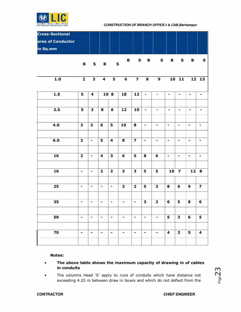
2.2.3 Maximum number of PVC insulated 650/1100V grade/copper
conductor cable conforming to IS:694-1990
Nominal 20mm 25mm 32mm 38mm 51mm 64mm
CONSTRUCTION OF BRANCH OFFICE-I & CAB,Berhampur
CONTRACTOR CHIEF ENGINEER
Pa
ge2
3
Notes:
• The above table shows the maximum capacity of drawing in of cables
in conduits
• The columns Head ‘S’ apply to runs of conduits which have distance not
exceeding 4.25 m between draw in boxes and which do not deflect from the
Cross-Sectional
area of Conductor
in Sq.mm
B S B S B S B S B S B S
1.0 2 3 4 5 6 7 8 9 10 11 12 13
1.5 5 4 10 8 18 12 - - - - - -
2.5 5 3 8 6 12 10 - - - - - -
4.0 3 2 6 5 10 8 - - - - - -
6.0 2 - 5 4 8 7 - - - - - -
10 2 - 4 3 6 5 8 6 - - - -
16 - - 2 2 3 3 5 5 10 7 12 8
25 - - - - 3 2 5 3 8 6 9 7
35 - - - - - - 3 2 6 5 8 6
50 - - - - - - - - 5 3 6 5
70 - - - - - - - - 4 3 5 4

CONSTRUCTION OF BRANCH OFFICE-I & CAB,Berhampur
CONTRACTOR CHIEF ENGINEER
Pa
ge2
4
straight run by an angle of more than 15 degrees. The columns heads ‘B’
apply to runs of conduit which deflect from the straight by an angle of more
than 15 degrees.
• Conduit sizes are the nominal external diameters.
Access and Drainage
• The conduit system shall be rewirable, that is, draw boxes must be
accessible for the purpose. Where boxes are concealed, their covers shall be
flushed with the finished surface.
• The need for accessibility notwithstanding, the conduit system shall be
protected against the ingress of water and impurities. When installed,
conduits shall be kept dry and free of debris with approved pipe plugs or
caps. Such plugging is especially essential prior to pouring concrete for
concealed installation. As for boxes, they shall be covered by steel plates
prior to concreting.
• When installed outdoor, and in situations liable to condensation of moisture,
conduits shall be arranged to be self draining, so that water may drain to
low points which are fitted with a drain plug. Conduits laid under concrete
floors shall have watertight floor-traps of approved detail for access of these
drainage points.
• Conduits run on surfaces other than structural steel members shall be
secured using galvanized space bar saddles and brass fixing screws.
Spacing of saddles shall not exceed 1.2 m for conduit sizes up to and
including 25 mm and 1.8 m for sizes 32 mm and above.
• Conduits run on structural steel shall be secured using girder clips or an
approved clamp. These conduits and those run in the vicinity of structural
steel shall be bonded to the steelwork using an efficient and permanent
metallic connection. The conduits shall not in any way be under mechanical
stress.
• All conduit boxes except loop-in patterns shall be fixed direct to the building
structure in addition to the support provided by the conduits.
• Conduits terminating into surface boxes shall be secured by a minimum of 3
saddles at not less than 32 mm, 150 mm and 300 mm respectively from the
box.
• Conduits shall be painted with an approved paint to blend with visual
environment. A zinc rich undercoat shall be provided before painting the
final coat.
2.2.4 Deleted.
2.2.5 Deleted
3.0 WIRES AND CABLES
3.1 GENERAL
3.1.1 Work Description

CONSTRUCTION OF BRANCH OFFICE-I & CAB,Berhampur
CONTRACTOR CHIEF ENGINEER
Pa
ge2
5
The design, manufacturing, testing and supply of single core PVC insulated 1.1 KV
grade stranded twisted wires shall comply with following standards with update
amendments under the specifications.
IS-3961: Current rating for cables.
IS-5831: PVC insulation and sheath of electric cables.
IS-694: PVC insulated cables for working voltage up to and including 1100 volts.
IEC-54 (I): PVC insulated cable.
Copper/ Aluminum stranded twisted conductor PVC insulated wires shall be used
in conduit as per item of work. Aluminum wires for power cables and copper wires
for control cables shall be used.
The wires shall be color coded - (red, yellow, blue) for Phases, black for Neutral
and green for Earth.
Progressive automatic in line indelible, legible and sequential marking of grade,
voltage, capacity and length in meters shall be embossed at every meter on the
outer sheath of cable.
The design, manufacture, testing and supply of the cable under these
specifications shall comply with following standards latest edition of:
IS: 8130: Conductors for insulated electric cables and flexible cords.
IS: 5831: HRPVC / HR PVC insulation and LSZH sheath of electric cables.
IS: 3975: Mild steel wires, strips and tapes for armoring cables.
IS: 3961: Current rating of cables.
The routing and minimum rated current carrying capacity of the LV power cables
shall be indicated on the Drawing. The Contractor shall consider the manufacturer
data and engineering for cable sizing and to ensure that it meets the conditions of
grouping, ambient temperature etc.
All LT cables for normal power/control circuits within buildings shall be XLPE
insulated and PVC sheathed Aluminum conductor and control cables shall be PVC
insulated and PVC sheathed copper conductor respectively.
All LT cables, for emergency power circuits serving emergency light, Fire
Protection System, Security Systems, emergency communication systems, etc.
with back-up from UPS systems or incoming and outgoing from the Emergency
Main Switchboard, shall be fire resistant as required.
Armoured Cables in service duct, open trench, direct-laid underground in soil.
Non-armoured cables shall only be laid in conduits for mechanical protection.
3.1.2 Standards
All cables shall be manufactured and constructed in accordance of the
following standards with the latest revision:

CONSTRUCTION OF BRANCH OFFICE-I & CAB,Berhampur
CONTRACTOR CHIEF ENGINEER
Pa
ge2
6
1. IS: 694
: HRPVC/XLPE insulated (heavy duty) electric cables
for
working voltage up to and including 1100 volts.
• IS: 424-1475(F- : Power cable-
flammability test. 3)
• IS: 7098(I): Specification for cross-linked polyethylene
insulated
LSZHPVC sheathed cable for working voltage up to
1.1
KV.
4. IS: 1554
: Specification for PVC insulated (heavy duty)
electric
cables for working voltages up to and including
1100
volts.
• ASTM-D: 2863 : Standard method for measuring the minimum
oxygen concentration to support candle-like
combustion of plastics (Oxygen Index).
• ASTM-D: 2843 : Standard test method for measuring the
density of smoke from the burning or
decomposition.
• IEEE: 383: Standard for type of tests Class-IE, Electric cables, field
splices and connections for power generation
station.
• ASTME:662/ : Standard test method for specific optical density
of
IEC: 754(x) smoke generated by solid materials
9. IS: 10418 : Cable drums.
10 IS-10810 : Testing method of cable.
11. IS-6121 : Cable glands.
12. IS-9537 : Rigid steel conduit.
The manufacturing of the cable shall also conform to the requirements of all
relevant local codes, as applicable, together with the additional requirements
referred to in the approved Specification and Drawings of EPC contractor. Only
more stringent specification shall be followed.
3.1.3 Submission

CONSTRUCTION OF BRANCH OFFICE-I & CAB,Berhampur
CONTRACTOR CHIEF ENGINEER
Pa
ge2
7
All technical submissions shall be approved by the EPC contractor prior to the
respective stages of construction with respect to the approved design and
development documents. In case of major deviations, it shall be brought under
the notice of LICI for its review and approval. As a minimum requirement, the
submission shall include the following:
Equipment submission with manufacturer’s data
Sample submission
• Shop Drawings of the cable route showing the co-ordinated routing of cables,
arrangement on cable trays, methods of fixing of cable trays and cables, etc. All
conduits including concealed conduit routing drawings shall also be included
• Cable test reports and IS Certification
• Cable schedule indicate the following data include:
• Cable code and type and installation method
• Cable feed from and to server
• Cable route length and voltage drop
• Cable capacity and
• Upstream protection breaker rating
The cable schedule shall be prepared in accordance to the cable manufacturer’s
data.
3.2 PRODUCT
3.2.1 LT Cables
• The cables shall be suitable for laying in racks, ducts, trenches conduits and
under-ground buried installation with uncontrolled back fill and chances of
flooding by water.
• They shall be designed to withstand all mechanical, electrical and thermal
stresses under steady state and transient operating condition.
• The aluminum/ copper wires used for manufacturing the cables shall be true
circular / sector in shape before stranding and shall be of uniformly good
quality, free from defects. The conductor used in manufacture of the cable
shall be of H2 grade.
• The cable should withstand 2.5 kA for 1 Sec. with insulation armour insulated
at one end. Bidder shall furnish calculation in support of capability to
withstand the earth fault currents. The current carrying capacity of armour
and screen (as applicable) shall not be less than the earth fault current values
and duration.
• The fillers and inner sheath shall be of non-hygroscopic fire retardant
materials and shall be suitable for the operating temperature of the cable.
Filler and inner sheath shall not stick to insulation and outer sheath.

CONSTRUCTION OF BRANCH OFFICE-I & CAB,Berhampur
CONTRACTOR CHIEF ENGINEER
Pa
ge2
8
• Progressive automatic in line indelible, legible and sequential marking (grade,
voltage, capacity, length - in meters) shall be embossed at every meter on
the outer sheath of all cables and at every 1 meter ‘LSZH marking in case of
‘LSZH cables.
• IS: 3975 method (b) for strip / wire armouring shall only be acceptable. For
single core cable aluminium wire armouring shall be used.
• Allowable tolerance on the overall diameter of the cables shall be + 2mm.
• The normal current rating of all HRPVC/XLPE insulated cables shall be as per
IS: 3961.
• A distinct inner sheath shall be provided by pressure extrusion process for all
multi cores armoured and unarmoured cables as per IS: 5831.
• Outer sheath shall be provided by extrusion process as per IS: 5831.
• The breaking load of armour joint shall not be less than 95% of that armour
wire. Zinc rich paint shall be applied on armoured joint surface.
• In plant repairs to the cables shall not be accepted.
• All the cables shall be supplied in non-returnable drums as per IS: 10418.
• Fire Survival Cables
Multi core Al / Cu Conductor XLPE/ Cross linkable Low Smoke Halogen
Free insulated with Fire rated Glass Mica Tape, LSZH inner and outer
Sheathed, Armoured with GI Strip/ Wire Fire Survival Cable.
Basic design shall be as per BS: 7846-2009, Fire resistance of the cable shall
be as per BS:8491-2008 & 8434-2:2003
Inspection
All cables shall be inspected on receipt of the same at site and checked for any
damage during transit.
Joints in Cables
Cable drum length and sizes of cable lengths required may be checked carefully
before cutting the cables from drum.
The contractor shall take care that the cables received at site are distributed to
various locations in single length as far as possible to ensure maximum
utilization. Where the joints are unavoidable, the same is to be done with
approval from the Owner/LICI . The joints shall be done by qualified jointer
strictly in accordance with manufacturer’s instruction / drawings in presence of
Engineer-in-charge.
Joint Boxes for Cables
The cable joint boxes shall be of appropriate size suitable for type of cable of
particular voltage rating.
Cable Joints
• All cable joints materials shall be of standard make and suitable to
requirement. On jointing of cables in the joint box the cable compound shall

CONSTRUCTION OF BRANCH OFFICE-I & CAB,Berhampur
CONTRACTOR CHIEF ENGINEER
Pa
ge2
9
be filled in accordance with manufacturer’s instructions and in approved
manner. All straight through joints shall be done in epoxy mould boxes with
epoxy resins. Straight through joints shall not be permitted unless the length
of run is in excess of cable drum.
• End terminations of cables more than 1.1 KV grade shall be done with epoxy
mould boxed and epoxy resin. Cable glands shall be 1.1KV grade double
compression type and made to tin plated heavy-duty brass casting and
machine finished. Glands shall be of robust construction capable of clamping
cable and cable armour, firmly without injury of cable.
• All washers and hardware shall be made of brass tinned. Rubber components
used in the glands shall be made of neoprene of tested quality.
• Cable lugs shall be tinned copper / aluminium solder less crimping type
conforming to IS: 8309 suitable for aluminium or copper conductor.
• Crimping of terminals shall be done by using Corrosion inhibitory compound,
with crimping tool.
• Fire resistant paint has to be applied 1 Meter on either side of cable joint.
• The contractor shall liaise fully with all other contractors to achieve an
efficient and properly coordinated installation where equipment has to be re-
positioned due to lack of site liaison; no extra cost shall be incurred by the
client.
XLPE HT Cables (Up to 11KV)
The cross linked polyethylene (XLPE) cable shall be aluminium conductor PVC
outer sheath steel strip armoured over inner sheath construction. XLPE cable
shall conform to testing in accordance with IS: 7098 (Part-I) 1977 and (Part-II)
1973. The screening shall be done on individual cover. The armouring applied
over the common covering shall be flat steel wires. Each and every length of
cable shall be subjected to routine test.
The termination and jointing techniques for XLPE cables shall be by using heat
shrinkable or push on cable jointing kits.
While laying underground cables in ducts care should be taken so that any
underground structures such as water pipes, sewerage lines etc. are not
damaged. Any telephone or other cable coming in the way shall be properly
protected as per instructions of the Engineer-in-charge.
After laying and jointing work is completed High Pot test shall be performed in
presence of Engineer-in-charge and test results submitted for approval in order
to ensure that they have not been damaged during or after the laying of cables.
In case, the test results are unsatisfactory, the cost of all repairs and
replacement and all extra work of removal and relaying will be made good by the
contractor without any extra cost.
Note: All other procedure will be followed as per L.T. cables.
3.3 EXECUTION
CONSTRUCTION OF BRANCH OFFICE-I & CAB,Berhampur
CONTRACTOR CHIEF ENGINEER
Pa
ge3
0
3.3.1 Erection of Cables
Notwithstanding the cable routes indicated on the Drawings the Contractor shall
be entirely responsible for the supply of correct lengths of the cables to be
installed and for all allowances for connecting and terminating the cables to the
switchgears and transformers respectively. The Contractor shall submit proposed
cable routes including details of supports for the cables for approval before
installation. The cable shall not be run in places other than corridor, passageway,
electrical riser or other designated areas subject to the Engineer’s approval. The
cost of support shall be deemed to have included in the Contract.
3.3.2 Cable Pulling
Winching of cables through ducts / pipes shall only be carried out with the
approval of the Engineer-in-charge in which event a pulley eye shall be attached
to the conductors. Cable shall be run in neat and orderly manner to allow space
for future cabling and maintenance. Under any circumstances the cable shall not
run diagonally across a room, cable basement, corridor, etc.
A cable sheath stocking may be employed or cables where no undue stress in the
sheath is likely to occur. Care shall be taken to ensure that the draw strain is
applied to the armouring and protected during drawing against damage.
3.3.3 Cable Laying
The cable drum shall be placed on jacks before unwinding the cable. Great care
shall be exercised in laying cables to avoid forming links. At all changes in
directions in horizontal vertical places, the cable shall be bent with a radius of
bend not less than 8 times the diameter of cable.
The cable of 1.1KV grade shall be laid not less than 750mm below ground level in
a 375 wide trench (throughout). Where more than one cable is to be laid in the
same trench, the width of the trench shall be increased such that the inter axial
spacing between the cables except where otherwise specified is at least 150mm
minimum or as per site requirements or as approved by the Engineer-in-charge.
Where single core cables are used in multiphase systems, the cables shall be
installed in trefoil where possible.
In case the cables are laid in vertical formation due to unavoidable circumstance
the depth per tier shall be increased by 200 mm (minimum). Cable shall be laid
in reasonably straight line, where a change in direction takes place a suitable
curvature shall be i.e. either 20 times the dia meter of the cable or the radius of
the bend shall not be less than twice the diameter of the cable drum or
whichever less is. Minimum 3 meter long loop shall be provided at both sides of
every straight through joint & 3 meters at each end of cable or as directed at
site.
Greater care shall be exercised in handling the cable in order to avoid forming
‘Kinks’. The cable drum shall convey on wheels and the cable unrolled in right
direction as indicated on the drum by the manufacturer. The cable shall be pulled
over rollers in the trench steadily and uniformly without jerks and strains.
Cables laid in trenches in single tier formation, 10 cms all- around sand
cushioning is to be provided below and above the cable before a protective cover

CONSTRUCTION OF BRANCH OFFICE-I & CAB,Berhampur
CONTRACTOR CHIEF ENGINEER
Pa
ge3
1
is laid. For every additional vertical tier. The 30 cm of sand cushion is provided
over the initial tier. The cable shall be protected by 2nd class brick of size not
less than 230 x 115 x 75mm, stone tiles/ RCC curved channel be placed on top
of the sand breadth wise for the full length of the cable and where more than one
cable is to be laid in the same trench the brick shall cover all cables and project
at least 8 cms over the outer sides of the end cables.
Filling of trenches shall be done after sand cushioning and tiles or bricks lying
and inspection is carried out by the Engineer-in-charge (Refer drawing). Back fill
for trenches shall be filled in layer not exceeding 150 mm. Each layer shall be
properly rammed & consolidated before laying the next layer.
PVC pipe shall be provided on all road crossing. The size of the pipe shall be
above the size of the cable. Minimum 100mm dia. pipes are to be provided. The
pipe shall be laid in ground with special arrangement and shall be cement jointed
and concreting of 1:5:10 shall be provided as per relevant IS with latest
amendment. Nothing extra shall be paid on this account. Cable route markers at
interval of 30 meters and at the point of direction change shall be provided to
indicate cable path. Aluminum strip cable tag of 20mm wide with engraved tag
no. shall be provided at both ends of cable.
Where the cables are laid in ducts (pucca trenches) inside the building, they will
be laid on MS rack/ cable trays grouted on trenches walls. Cables passing through
floors shall be protected from mechanical damage by steel channel to a height of
one meter above the floor. Sleeve shall be provided in the wall for crossing of
cables.
Where the cables are laid in open (in building) along walls, ceiling or above false-
ceiling, cable rack (ladder type) or cable tray shall be provided. The size of the
cable tray or rack shall depend on the number of cables to pass over that rack.
Cable tray/rack shall be properly supported through wall/ceiling according to the
site conditions. Cable laid on tray riser shall be neatly dressed & clamped at an
interval of 1000 mm & 750mm for horizontal & vertical cable run respectively
either side at each bend of cable. All power cables shall be clamped individually &
control cables shall be clamped in groups of three or four cables. Clamps for multi
core cables shall be fabricated of 25x3 GI flats. Single core power cable shall be
laid in trefoil formation & clamped with trefoil clamps made of PVC/fiber glass.
Cable openings in wall/floor shall be sealed by the contractor suitably by Hessian
tape & Bitumen compound or by any other proven material to prevent ingress of
water.
After the cables are laid, shall be tested as per IS and the results submitted to
LICI Engineer and in case the results found unsatisfactory, all the repairing/
replacing of cables will be done by the contractor free of charge.
3.3.4 Internal Wiring
The scope of work under this section covers installation and wiring for lights,
ceiling fans, exhaust fans, call bells, AC, geysers and power sockets, independent plug
points, computer points etc., The wiring shall generally be done using ISI FRLS PVC
insulated stranded copper conductor wires in ISI FRLS PVC Heavy duty conduits as called
for including providing modular switches, sockets, plug tops, electronic fan regulators,

CONSTRUCTION OF BRANCH OFFICE-I & CAB,Berhampur
CONTRACTOR CHIEF ENGINEER
Pa
ge3
2
outlet boxes and all related accessories etc. All the wiring installation shall be as per IS:
732 with latest amendment. PVC insulated copper conductor cables as specified in bills of
quantity shall be used for sub- circuit runs from the distribution boards to the points and
pulled into conduits. They shall be twisted copper conductors with thermoplastic
insulations of 1100 volts grade. Colour Code for wiring shall be followed.
Looping system of wiring shall be used, wires shall not be jointed. Where
joints are unavoidable, they shall be made through approved mechanical connectors with
prior permission of the LICI . No reduction of strands is permitted at terminations. No
wire smaller than 1.5 sq.mm shall be used. Wherever wiring is run through
trunkings or raceways, the wires emerging from individual distributions shall be bunched
together with cable straps at required regular intervals. Identification ferrules indicating
the circuit and DB number shall be used for sub main sub-circuit wiring. The ferrules
shall be provided at both end of each sub main and sub-circuit.
Where single phase circuits are supplied from a three phase and a neutral
distribution board, no conduit shall contain the wiring fed from more than one phase. In
any one room in the premises where all or part of the electrical load consists of lights,
fans and/or other single phase current consuming devices, all shall be connected to the
same phase of the supply. Circuits fed from distinct sources of supply or from different
distribution boards or through switches or MCBs shall not be bunched in one conduit. In
large areas and other situations where the load is divided between two or three phase,
no two single phase switches connected to different phase shall be mounted within two
meters of each other. All splicing shall be done by means of terminal blocks or
connectors and no twisting connection between conductors shall be allowed.
Industrial sockets shall be of polycarbonate and deeply recessed contact tubes. Visible
scraping type earth terminal shall be provided. Socket shall have self adjustable spring
loaded protective cap. Socket shall have MCB/ELCB/RCCB as specified in the schedule of
work.
3.3.5 Fire Seal System
All the floor/wall opening provided for cable crossing shall be sealed by fire seal system.
The fire proof sealing system shall fully comply with the requirements of relevant
IS/BS:476 Part-B. The fire proof seal system shall have minimum one hour fire
resistance rating.
The fire proof seal system shall be physically, chemically, thermally stable and shall be
mechanically secured to the masonry concrete members. The system shall be
completely gas and smoke tight, anti rodent and anti-termite.
The material used in fire proof seal system shall be non-toxic and harmless to
the working personnel.
Type of fire proof seal system shall be foaming type or flame mastic type compound or
approved equivalent.
After laying and jointing work is completed, high voltage test should be applied
to all cables to ensure that they have not been damaged during or after the laying
operation and that there is not fault in the jointing.
Cables for use on low and medium voltage system (1.1KV grade cables) should
withstand for 15 minutes a pressure of 3000V, DC applied between conductors and also

CONSTRUCTION OF BRANCH OFFICE-I & CAB,Berhampur
CONTRACTOR CHIEF ENGINEER
Pa
ge3
3
between each conductor and sheaths. In the absence of pressure testing facilities it is
sufficient to test for one minute with a 1000V insulation tester In case the test results
are unsatisfactory the cost of repairs and replacements and extra work of removal &
laying will be made good by the contractor.
Cable shall be installed so that separations shown in the table below are observed.
Si No Particulars Distance
1. ELV & LT 230 V/433 V-ELV & LT 230V/433V 50 mm
2. HT cables to ELV& LV cable 300 mm
3. LT cables to Control cable (Network) 350 mm
4. All cables to hot pipe work 200 mm
3.3.6 Factory Tests
Each type of cable specified shall be fully type tested according to IEC 502 and
the appropriate British Standards. The types and sizes of cables required are
shown on the Drawings. Should the Engineer require it, the Contractor shall
submit reports issued by a national or international testing authority on type test
that have been successfully performed on the cable for his approval. The type
test shall include the following test:
• Partial discharge test;
• Bending test, plus partial discharge test;
• Tan measurement as a function of the voltage and capacitance
measurement;
• Tan measurement as a function of the temperature;
• Heating cycle test plus partial discharge test;
• Impulse withstand test, followed by a power frequency voltage
test;
• Medium-voltage alternating current test;
• Type test (non-electrical) as stipulated in IEC 502, Table VI.
• Cable routine test shall be conducted at factory in accordance with IEC 502 for
the following tests:
• Measurement of the electrical resistance of conductors
• Partial discharge test,
• 4-hour HT test
3.3.7 Site Acceptance Test
The Contractor shall supply all necessary testing equipments for site testing. When
required, these testing equipments shall be calibrated at the expense of the Contractor
at a recognized national laboratory.
The Contractor shall engage an Authorized Medium Voltage Testing Engineer who is
recognized by SEB to perform all site tests. In addition to SEB’s requirements and those
recommended by the manufacturer, the following tests shall be carried out:
• Continuity test

CONSTRUCTION OF BRANCH OFFICE-I & CAB,Berhampur
CONTRACTOR CHIEF ENGINEER
Pa
ge3
4
• Earth test
• Polarity test
• Insulation resistance test
• DC high voltage test.
The test voltage shall be in accordance with SEB’s requirements and Engineer’s approval.
4.0 WIRING DEVICES
4.1 GENERAL
4.1.1 Work Description
The drawings for the lighting and power points indicate approximate position of
all light fittings, switches, power outlet points, isolating switch points etc. The
actual position of all fittings, switches, the wiring details and cable routes shall be
co-ordinated with other trades at site and submitted for the approval of the
Engineer-in-charge. All time and cost required for adjusting the layout or
complete installation to suit site requirement is included.
To determine the exact positioning of lighting and power points due consideration
shall be given, for selection of the most accessible routes for wiring, convenience
of switching and operational requirement of the installation.
No extra cost will be paid should the final positions be relocated within
the same room.
For the purpose of specification and related drawing, each lighting & power point
circuit shall be coded with a prefix to indicate the corresponding distribution
board number.
This section included the specification of the following:
• Distribution boards
• Miniature circuit breakers
• Earth leakage circuit breakers
• 6A Switch Socket Outlet
• 16A Switch Socket Outlets
• Isolating Switches
• Conduit Boxes
• Contactors
• Dimmers Switch
• Time Switch
• Power points
• Water Heater Switches
• Bell Push Switches
4.1.2 Standards
CONSTRUCTION OF BRANCH OFFICE-I & CAB,Berhampur
CONTRACTOR CHIEF ENGINEER
Pa
ge3
5
The complete wiring installation shall be engineered according to manufacturer
data and constructed in accordance with the latest revision of the IS and the
appropriate BS/IEC
In the adoption of standards and requirements, the Contractor shall take the
following precedence:
• Engineer’s decision
• Local codes of practice
• Drawings
• Specification
• International standards and requirements
4.1.3 Submission
All technical submissions shall be approved by the EPC contractor prior to the
respective stages of construction with respect to the approved design and
development documents. In case of major deviations, it shall be brought under
the notice of LICI for its review and approval. The submission shall include the
following as a minimum requirement
• Equipment catalogues submission with manufacturer’s data
• Sample submission include all wiring accessories
• Shop Drawings of the lighting and power positions, circuit numbers, cable
routings, switching arrangement, mounting height, etc. The positions and
mounting heights shall be coordinated with other services. Fixing details of
all wiring accessories shall also be included.
• Drawings showing the installation details
• Labeling system
• Builder’s works requirement.
4.2 PRODUCT
4.2.1 Lighting Point Installation
Surface mounted light fitting shall terminate at junction box having entries
appropriate to the run of conduit. This shall be complete with porcelain / PVC
connector suitable for the size and number of connections and wiring points to be
connected with the specified fitting. Wiring to the light fittings within the false
ceiling space shall be by means of heat resistant (butyl or silicon rubber insulated
to BS 6500) cables i.e. between the junction box and the lamp holder/terminal
blocks, in flexible conduits.
At every light fitting, an approved type earth terminal shall be provided for
connection of the circuit protective conductor of the final circuit. Ferrous metal
work shall be of minimum of 1mm thickness and treated against corrosion by
galvanising after welding or lead primer or other approved process. Metal work
shall be painted with one priming coat, one under-coat and two final coats with
stove-enamelled matt white paint unless otherwise specified.

CONSTRUCTION OF BRANCH OFFICE-I & CAB,Berhampur
CONTRACTOR CHIEF ENGINEER
Pa
ge3
6
Cables used for internal wiring of the lighting fittings shall be with appropriate
type and size, number with conductor of size not less than 1.5 sq mm
single core. The insulation of the cables shall withstand the maximum
temperature throughout the life of the fitting. It will be subject to normal use
without deterioration which could affect the safety of the fitting.
Cables within the lighting fittings shall be neatly bundled by nylon self locking
cable ties. Wiring shall be properly routed and secured away from control gear
etc. wherever possible.
All cable terminations within the light fittings shall be suitably shrouded.
All light fittings shall be supported with appropriate fixing accessories such as
clips, supporting brackets, suspension sets, nuts, washers, screws etc. for their
proper installation on different types of ceiling panels. Suspension sets shall be of
adjustable type suitable to carry the weight of the lighting fittings unless
otherwise stated or indicated on drawings. The suspension sets shall be generally
of 900mm length. Exact lengths required shall be provided to suit the site
requirement.
All lamps in operational condition with proper control gear shall be provided
together with the light fittings as required and specified.
4.2.2 Switches
Lighting switches unless otherwise specified, shall be MODULAR single pole, quick
make and break, silent action type with solid silver alloy contacts and totally
enclosed for flush or surface mounting as required. Lighting switches shall be
suitable for indoor or outdoor service according to location housed in standardized
purpose manufactured galvanized steel boxes completed with conduit knockouts
made up into single or multi-gang units employing a grid switch system of fully
interchangeable components at standardized fixing centers of matching switches
of different types and ratings but of identical dimensions, push buttons, neon
indicator lamps, blanking units, grids, steel boxes and plates all capable of
integration into standard composite assemblies in any combination as required.
Grids shall be adjustable for variation in depth of plaster and for squaring errors
and of the same type for surface or flush mounting.
Switches located on brick or concrete walls shall be mounted in horizontal
arrangement in plaster depth steel boxes or in galvanized steel boxes using box
suspension straps and cover plates. Countersunk screws shall be provided for
fixing to the conduit boxes. Switches for external use shall be of weatherproof
construction with IP-65 rating unless otherwise specified. Samples of all switches,
conduit boxes and plaster depth boxes shall be submitted to the Engineer for
approval prior to installation.
Switches shall be rated for 6 Amps (minimum light switch rating 6 Amps),
16Amps or 20Amps (as determined by circuit load). Inductive lighting circuit
shall be assessed at twice the steady state connected load current. One or two
ways switch as indicated on the drawings be fixed generally at a height of
1200mm from floor level in rooms. The switch shall possibly be located
inside the room on the handle side of the door as close as practicable.

CONSTRUCTION OF BRANCH OFFICE-I & CAB,Berhampur
CONTRACTOR CHIEF ENGINEER
Pa
ge3
7
Earth continuity terminal shall be provided and connected to the circuit
protective conductor at every lighting switch position. Single pole switches shall
be connected to break the phase wire of the supply. The neutral wire shall not be
routed through switch boxes. Switches which are mounted in the same location
shall be of multi-gang type, of the maximum number of gangs available. All
switches used shall be of approved or prescribed items as required by local
Authorities. Circuit from different phase and circuit from emergency power
should have separate switch plate.
4.2.3 Deleted.
4.2.4 6 AMP Switch Socket Outlets
Switch socket outlets shall be as per BS: 1363 single pole 6 Amp 3 round pin
shuttered outlets, for indoor service except otherwise specified and suitable for
surface or flush mounting according to location.
Switches shall be of the quick-make and break type silent action totally enclosed
with solid silver alloy contacts. Switched socket outlets for indoor use shall be
housed in suitable galvanized steel boxes as per BS: 4662 with conduit
knockouts. Types and finishes of socket plates shall match those for the lighting
switches.
Generally switch socket outlets shall be positioned 300 mm above floor level
except in plant rooms etc. where they shall be positioned 1400mm above floor
level or 150mm above counters or benches as per requirement.
Switch socket outlet in all rooms/hall shall be of the metal clad type, with
recessed or protected switch dolly, mounted in flush or surface conduit boxes as
specified. All switch socket outlets used shall be of an approved quality.
4.2.5 16 AMP Switch Socket Outlets
16Amp switch socket outlets shall be 3 pin round type to BS: 546 shuttered, of
finished similar to 6Amp switch socket outlets and flush mounted in galvanised
steel conduit boxes to BS: 4662 requirements.
4.2.6 Weatherproof Enclosure for MCB
Weatherproof enclosure shall be of the high impact, water resistant to IP-65. The
isolator provided shall complete with lockable device. MCB shall be 2-pole, 4-pole
as specified.
4.2.7 Floor Box-Access Outlet.
All plates shall be made from stainless steel or equal approved, heavy duty trap
cover. All plates are to be mounted flush with surface and are to be aligned
correctly. Access Outlet should carry service plates for providing services i.e.
Power, Data & Telecom. The system must comply the relevant specification & IEC
61084 standards. The system should have Positive Double Earthing connections.
4.2.8 Deleted.
4.2.9 Deleted.
4.2.10 Miniature Circuit Breaker

CONSTRUCTION OF BRANCH OFFICE-I & CAB,Berhampur
CONTRACTOR CHIEF ENGINEER
Pa
ge3
8
The MCB shall be suitable for manual closing, opening and automatic tripping
under overload and short circuit. The MCB shall also be trip free type. Single pole
/ three pole versions shall be furnished as required. The MCB shall be rated for
10KA fault level of C series.
The MCB shall be suitable for housing in the lighting boards and is suitable for
connection at the outgoing side by tinned cable lugs and for bus-bars connection
on the incoming side. The terminal of the MCB and their open and close
conditions shall be clearly / indelibly marked. The MCB shall generally conform to
IEC/ IS: 60898
4.2.11 Earth Leakage Circuit Breaker
ELCB shall be 4 pole 415 volts 50Hz, 100mAsensitivity. These shall be of
approved make. The rating of the ELCB shall be as required. These shall be
suitable for manual closing and opening and for automatic tripping under earth
fault circuit of 100mA as specified in item of work. The enclosure of the ELCB
shall be moulded from high quality insulating material. The material shall be fire
retardant, anti tracking, non-hygroscopic, impact resistant and shall with stand
high temperature. All parts of switching mechanism shall be non-greasing, self
lubricating material so as to provide consistent and trouble free operation.
Operation of ELCB shall be independent of mounting position and trip free type.
4.2.12 Lighting/Small Power Distribution Boards
Distribution boards shall be of standard make with MCBs as per approved make
given. Distribution boards shall be of steel sheet construction double door all
welded enclosure of IP42 protection and powder coated painted.
Ample clearance between the conductors of opposite pole and sheet steel body
shall be maintained in order to obviate any chance of short circuit. Removable
conduits entry plates shall be provided at top and bottom to facilitate drilling
holes at site to suit individual requirements.
Additional / separate adopter box of suitable size shall be provided to
accommodate wires, cables and No. of conduits etc. at no extra cost.
The MCB shall be mounted on high grade rigid insulating support and connected
by electrolytic copper bus bars. Each incoming MCB shall be provided with
solder-less cable sockets for crimping. Phase separation barriers made out of arc
resistant materials shall be provided between the phases. Bus bars shall be
colour coded for phase identification. Distribution boards shall be recessed in wall
or mounted on surface of wall with necessary mounting arrangement. The
mounting height shall not exceed 1200mm from finished floor level. Distribution
board shall be provided with proper circuit identification name plate and
danger sticker/plate as per requirement.
All the distribution boards shall be provided with engraved name plates with
‘lighting’, ‘power’ or ‘UPS’ with DB Nos., as the case may be.
Each DB shall be provided with circuit list giving details of each circuit. All the
outgoing circuit wiring shall be provided with identification ferrules giving the
circuit number & phase.

CONSTRUCTION OF BRANCH OFFICE-I & CAB,Berhampur
CONTRACTOR CHIEF ENGINEER
Pa
ge3
9
Each distribution board shall have separate neutral and earth connection bar
mounted within the DB each having the same number of terminals as the total
number of outgoing individual circuits from the distribution board. Conduit &
cable armouring shall be bonded together & connected to the distribution board
earth bar. Where oversized cables are specified due to voltage drop problems, it
shall be contractors responsibility to ensure that satisfactory terminal
arrangements are provided without an extra cost.
4.2.13 Telephone Outlets
Telephone outlets where called for shall be single or twin flush mounted type
suitable to receive the plug-in telephone cable lead to the approval of the
Telecom. The finish of the telephone outlet plates at various areas shall be as
specified for lighting switches.
4.2.14 Bell Push Switches
Bell push switches shall be flush-mounted having single-pole AC switch of 6
Amps rating and marked with bell symbol.
4.2.15 Deleted
4.2.16 Power Supply for Lighting at Wet Condition
Residual Current Circuit Breakers shall be provided individually for each circuits
serving lighting subject to wet condition.
5.0 LOW VOLTAGE SWITCHGEAR AND TESTED ASSEMBLY
5.1 GENERAL
This section covers the detailed requirements of medium voltage switchboard for
415 volts, 3 phase, 50 Hz, 4 wire system.
5.2 STANDARDS & CODES
Updated and current Indian Standard Specifications and Codes of Practice will
apply to the equipment and the work covered by the scope of this contract.
Low Voltage Switchgear Assemblies IEC61 439-1 & 2
Low Voltage switchgear & control gear IEC 60 947 /IS 13947: 1993
Part I : General rules
Part II : Circuit Breakers
Part III : Switches, disconnectors, switch disconnectors and fuse
combination units
Part IV : Contactors and Motor starters
Part V : Control circuit devices and switching elements
Degree of Protection of Enclosures for low voltage switchgear. IEC60529 /IS 2147:
1962
Internal arc – IEC 61641

CONSTRUCTION OF BRANCH OFFICE-I & CAB,Berhampur
CONTRACTOR CHIEF ENGINEER
Pa
ge4
0
5.3 SWITCHGEARS
5.3.1 General
The LV switchboards shall be as per the standards IEC 61439-1 & 2. The
switchboards and the associated equipment including switchgear, control gear,
Busbar supports, Busbar orientation, Busbar links etc. shall be identical in
construction to the assembly which has undergone the type test. The drawings of
the type-tested assemblies shall be made available for inspection.
The designs of the switchboards should be with switchgear manufacturer, and all
the mechanical drawings must be available in the factory beforehand.
Panel shall be tested of design as per Seismic Zone 4 of IS 1893 Part -1 2002.The
enclosures shall be designed to take care of normal stress as well as abnormal
electro-mechanical stress due to short circuit conditions. All covers and doors
provided shall offer adequate safety to operating persons and provide ingress
protection of IP 42 unless otherwise stated. Ventilating openings and vent outlets,
if provided, shall be arranged such that same ingress protection of IP 42 is
retained. Suitable pressure relief devices shall be provided to minimize danger to
operator during internal fault conditions.
The Main LT Panels have to be designed in such a way that no CTs are being used
for metering so as to eliminate the re-calibration for meter due to CT saturation
and CT burnout on fault. All metering and protection needs to be done via inbuilt
CT of the breakers.
The switchboard along with MCCB and connections should have been be type
tested design at CPRI /Independent international test house for short circuit,
temperature rise and dielectric tests of the ratings required.
Panel shall be rated for Impulse withstand capability as per standard for main
circuit as per IEC 61439 Clause 5.2.4 Rated impulse withstand voltage (Uimp) (of
the ASSEMBLY).
For operator safety IP2 X (touch proof) protection to be available even after
opening the feeder compartment door. The compartmentalization to be achieved
by using metal separators, use of PVC sheet / Hylem sheets shall not be allowed.
Main switchboard shall be form 4b, for form of separation only metallic covers
shall be used, Hylem/ PVC sheets shall not be allowed, rest of the panels shall be
minimum conform to form 4b design. All, MCCB of Main LT panel shall have
inbuilt earth fault protection. TTA panels shall be allowed from OEMs only.
5.3.2 Switchgears Configuration
The Switchboard shall be configured with MCCB's, MCB’s and other equipment as
called for.
The MCCBs shall be arranged in multi-tier formation only to facilitate operation
and maintenance.
The Switchboards shall be of adequate size with a provision of spare space to
accommodate possible future additional switch gear.
The switchgear devices and the enclosure design should be of same manufacturer
having valid Type Test Certificate.

CONSTRUCTION OF BRANCH OFFICE-I & CAB,Berhampur
CONTRACTOR CHIEF ENGINEER
Pa
ge4
1
All switchboards shall be factory built and design, project management, design
warranty, including performance warranty on the switch boards shall be from
original equipment (switchgear) manufacturers. The Panels shall be manufactured
by switchgear OEMs or their authorized system integrators / assembly
manufacturers/ franchisee, However the final responsibility & warranty shall be of
Switchgear OEM only.
5.3.3 Constructional Features
Switchboards construction shall employ the principle of compartmentalized and
segregation for each circuit.
Incomer and bus section panels or sections shall be separate and independent
and shall not be wired with sections required for feeder. The incomer panel shall
be suitable for receiving bus trunking or MV cable of size specified.
Switchboards shall be made up of requisite vertical sections, which when coupled
together, shall form continuous dead front switchboards. Switchboard shall be
readily extensible on both sides by addition of vertical sections after removal of
the end covers.
The switchboards shall be designed for use in high ambient temperature and
humid tropical conditions as specified. Ease of inspections, cleaning and repairs
while maintaining continuity of operation shall be provided in the design.
Neoprene gaskets between all adjacent units and beneath all covers shall be
provided to render the joints dust and vermin proof to provide a degree of
protection of IP 42/IP 54 as stipulated. The unused openings within the
switchboards shall be closed using suitable grommets.
Degree of Protection shall be IP42 or better.
Special care to be taken to ensure effective earthing of the frame and doors of
the switchboards. Each vertical section shall be provided with a rear or side cable
chamber housing the cable end connections and power/control cable
terminations. There should be generous availability of space for ease of
installation and maintenance with adequate safety for working in one vertical
section without coming into contract with any live parts. The design of the
switchboard shall allow standard extension chambers if required to accommodate
cables.
Some switchboards may be required to be installed against the wall, for such
application-documented designs shall be available.
Switchboard panels and cubicles shall be fabricated with CRCA Sheet Steel of
thickness not less than 2.0 mm and shall be folded and braced as necessary to
provide a rigid support for all components. The doors and covers shall be
fabricated from CRCA sheet steel of thickness not less than 2 mm. Joints of any
kind in sheet metal shall be seam welded and all welding slag ground off and
welding pits wiped smooth with plumber metal. The external covers provided
should have been subjected to minimum mechanical impact of IK09/10 as per
IEC to ensure specified degree of protection.
All panels and covers shall be properly fitted and square with the frame. The
holes in the panel shall be correctly positioned.

CONSTRUCTION OF BRANCH OFFICE-I & CAB,Berhampur
CONTRACTOR CHIEF ENGINEER
Pa
ge4
2
Switchboard shall be provided with “Danger Notice Plate” conforming to relevant
Indian Standards.
5.3.4 Switchgears Dimensional Limitations
The overall height of the switchgears /enclosures shall be limited to 2400 mm for
all the Busbar ratings and type of switch boards. The height of the operating
handle, push buttons etc. shall be restricted between 250 mm and 1800 mm from
finished floor level. Other dimensional limits if any are specified separately.
5.3.5 Switchgears Compartmentalization
For compartmentalized switchboards, separate totally enclosed compartments
shall be provided for horizontal bus-bars, vertical bus-bars, , MCCBs, and cable
alloys.
The main board shall be with Form 4b Construction with metallic shrouding only,
FRP is not acceptable.
Earthed metal or insulated shutters shall be provided between draw-out and fixed
portion of the MCCB such that no lives parts are accessible with equipment drawn
out. Degree of protection within compartments shall be at least IP 2X.
Sheet steel hinged lockable doors for each separate compartment shall be
provided and duly interlocked with the breaker in "ON" and "OFF" position.
For all Circuit Breakers separate and adequate compartments shall be provided
for accommodating instruments, indicating lamps, control contactors and control
MCB etc. These shall be accessible for testing and maintenance without any
danger of accidental contact with live parts of the circuit breaker, bus-bars and
connections.
For Some MCCB feeders for critical loads like UPS it may be required to have
operation only after opening the door, all other facilities like pad lockable rotary
handle to be provided for such feeder. It shall be possible to do this change
during execution of order each switchgear cubicles shall be fitted with label in
front and back identifying the circuit, switchgear type, rating and duty. All
operating device shall be located in front of switchgear only.
A horizontal wire way with screwed cover shall be provided at the top to take
interconnecting control wiring between vertical sections.
Separate cable compartments running the height of the switchboard in the case
of front access boards shall be provided for incoming and outgoing cables.
Cable compartments shall be of adequate size for easy termination of all incoming
and outgoing cables entering from bottom or top. The construction shall include
necessary and adequate and proper support shall be provided in cable
compartments to support and clamping the cable in the cable alley / cable
chamber.
5.3.6 Switchgears Bus Bars
Busbars shall be made of high conductivity, high strength Copper Busbars shall
be of rectangular cross sections, suitable for full load current for phase bus bars
and full rated current for neutral bus bar or as stipulated . Busbar shall be
suitable to withstand the stresses of fault level as specified .

CONSTRUCTION OF BRANCH OFFICE-I & CAB,Berhampur
CONTRACTOR CHIEF ENGINEER
Pa
ge4
3
Main Horizontal busbar and Neutral should be in same compartment. The bus bar
system may comprise of a system of main horizontal bus bars bus bar alloy on
either side in which the circuit could be arranged with front access for cable
entrances.
The bus bars shall be supported on non-breakable, non-hygroscopic epoxy resin
or glass fiber reinforced polymer insulated supports able to withstand operating
temperature as per Type Test Report of at regular intervals, to withstand the
forces arising from a fault level as stipulated . The material and the spacing of
the Busbar supports should be same as per the type tested assembly
Auxiliary buses for control power supply, space heater power supply or any other
specified service shall be provided. These buses shall be insulated, adequately
supported and sized to suit specific requirement. The material for auxiliary
supply bus will be insulated electrolytic copper wires. Clearances between phases
should be higher than IEC.
5.3.7 Switchgears Interconnection
For unit ratings up to 250 amps, PVC insulated 105 dg withstand, copper
conductor wires of adequate size to carry full load current shall be used. The
terminations of such interconnections shall be crimped. Solid connections shall be
used for all rating of above 250 amps.
All connections, tapings, clamping, shall be made in an approved manner to
ensure minimum contact resistance. All connections shall be firmly bolted and
clamp with .even tension. Before assembly joint surfaces shall be filed or finished
to remove burrs, dents and oxides and silvered to maintain good continuity at all
joints. All screws, bolts, washers shall be zinc plated.
5.3.8 Deleted.
5.3.9 Instrument Accommodation
Digital type voltmeter and ammeter and other instruments shall be flushed
mounted type of size 96 sq. mm conforming to class 1.5 to IS 1248 for accuracy.
All voltmeter shall be protected with MCBs.
Instruments and indicating lamps shall not be mounted on the Circuit Breaker
Compartment door for which a separate and adequate compartment shall be
provided and the instrumentation shall be accessible for testing and maintenance
without danger of accidental contact with live parts of the Switchboard.
For MCCBs, instruments and indicating lamps can be provided on the
compartment doors. The current transformers for metering and for protection
shall be mounted on the solid copper/ aluminum busbars with proper supports.
On all the incomers of switch boards ON/OFF indicators lamps shall be provided
suitable for operation on AC 230 volts supply. All lamps shall be protected by
MCBs.
For Incomer feeders MULTI FUNCTION METER shall be provided which shall
display A , V, Pf , Hz ,Kw , KVA, KVAr, Kwh , Kvarh, average and maximum
values , demand values , THD on current and Voltages, Individual harmonics up
to 31st level.

CONSTRUCTION OF BRANCH OFFICE-I & CAB,Berhampur
CONTRACTOR CHIEF ENGINEER
Pa
ge4
4
5.3.10 Wiring
All wiring for relays and meters shall be with PVC insulated copper conductor
wires. The wiring shall be coded and labeled with approved ferrules for
identification. The minimum size of copper conductor control wires shall be 2.5
sq. mm. Runs of wires shall be neatly bunched and suitably supported and
clamped. Means shall be provided for easy identification of wires. Identification
ferrules shall used at both end of wires. All control wires meant for external
connections are to be brought out on a terminal board. The cables and control
wires shall be suitable for withstanding 105 deg C.
5.3.11 Deleted
5.3.12 Deleted
5.3.13 Earthing
Continuous earth bus sized for prospective fault current to be provided with
arrangement for connecting to station earth at two points. Hinged doors / frames
to be connected to earth through adequately sized flexible braids.
5.3.14 Sheet Steel Treatment and Painting
Sheet steel used in the fabrication of switchboards shall undergo a rigorous
cleaning and surface treatment seven tank process comprising of alkaline
degreasing, descaling in dilute sulphuric acid and a recognised phosphating
process after which a coat of primer paint compactively with the final paint shall
be applied over the treated surface. Final paint coat of oven baked powder
coating, of minimum 50 micron thickness, of sheet approved by Engineer-in-
Charge shall then be provided.
5.3.15 Name Plates and Labels
Suitable engraved white on black name plates and identification labels of metal for all
Switchboards and Circuits shall be provided. These shall indicate the feeder number and
feeder designation.
5.3.16 Type test reports.
Switchboard configurations offered shall be CPRI /Independent international test house
tested for all the tests as per IEC61439-1 & 2 and internal arc tests as per IEC61641.
Copies of the test certificates shall be submitted with the tender.
5.3.17 Testing At Works
Copies of type test carried out at MCCB manufacturers works and routine tests carried
out at the switchboard fabricators shop shall be furnished along with the delivery of the
switchboards. Engineer-in-Charge reserves the right to get the switchboard inspected by
their representative at fabricators works prior to dispatch to site to witness the
followings. Physical variation and dimensional check. Verification of bill of material
Functional check
HV test
IR test

CONSTRUCTION OF BRANCH OFFICE-I & CAB,Berhampur
CONTRACTOR CHIEF ENGINEER
Pa
ge4
5
6.0 MEDIUM VOLTAGE PANELS
6.1 GENERAL
Medium Voltage power control centers (generally termed as switchboard panels)
shall be in sheet steel clad cubicle pattern, free floor standing type, totally
enclosed, compartmentalized design having multi-tier arrangement of the
incomers and feeders . The panels shall be of extensible type with provision of
bus bar extensions. All panels shall conform to the requirements of the latest
addition of IS and shall be suitable for 415 V, 3 phase AC supply or 230 V single
phase AC supply as required.
6.2 CONSTRUCTION
All switch board panels or power control centers of free standing type shall have a
bus bar chamber at the top and the cable compartment at the bottom or as
approved by the Developer/LICI s depending upon the specific requirements of
the job. The space between the bus chamber and cable compartment shall be
suitably compartmentalized to accommodate either air circuit breakers or molded
case circuit breaker of various ratings. The cable terminations shall be carried out
on the rear side of the panels for which adequate space and clamping
arrangements shall be provided. Where panels have to be installed with very little
access space at the rear, the cable terminations shall be carried out in suitable
cable alleys provided on the front of the panel. All the live parts shall be properly
shrouded with Bakelite barriers. All the equipment shall be accessible from the
front. However, protection relays, MULTI FUNCTION meter etc. may be mounted
on the rear side/front side. Arrangements and marking of bus bars, main
connections and wiring shall be in accordance with latest IS code. The structure
of the panel shall be robust and provided with adequate bracing’s to withstand
the operation of the equipment and stresses due to system short circuit. The
panels shall be fabricated out of best quality heavy gauge sheet steel. The panel
shall be machine pressed with punched openings for meters, indicating lamps etc.
The enclosure system shall be Modular in nature with bolted on construction.
Enclosure parts/kits shall be interchangeable to reduce downtime during
modification or maintenance work. Enclosure system and switchgear components
shall be from same manufacturer.
6.3 DIMENSIONS
All power control centers shall have dimensions of not more than that given on
the layout drawings. Panels arranged side by side shall have the same height and
depth. The height of the panel should be limited to 2400 mm. All the operating
levers, handles etc. of the highest unit shall not be at a height more than 1700
mm from F.F.L. For all incoming cables a removable gland plate will be provided
in the panel and a minimum distance of 300 mm will be provided between the
gland plate and the nearest terminal for proper dressing and termination of the
cable. All the components of a module will be mounted on a component plate
using the machine screws and taped holes (excepting the components mounted
on the door). These component plates should be fixed with bolts for easy
replacement. Standardization will be adopted while making these plates so that
the component plates of the same size modules can be changed from one module
to another. In case of panel of lengths more than 4 meters the fabrication of any

CONSTRUCTION OF BRANCH OFFICE-I & CAB,Berhampur
CONTRACTOR CHIEF ENGINEER
Pa
ge4
6
single section will be limited to a maximum length of 4 meters for the purpose of
shipping and shifting at the site. These sections will be assembled at the location
of installation with the help of nuts and bolts. While making these sections
consideration will be given to the place of sectionalizing and select the location
where the minimum electrical connections are transferred from one section to
another. All the hardware used in the assembly will be electroplated for protection
and neat appearance.
6.4 BUS BARS
The bus bars shall be suitable for 4 wire, 415 Volts, 50 Hz, system. The main bus
bar shall be of electrolytic copper conductor electrically conductor grade copper
made of high conductivity electricity conductor grade Copper and the size shall
be for minimum current density of 1.3 Amp per Sq. mm.. Joining of two copper
buses tinning will be done on the copper strips ends to a length equal to the lap
length of the joint plus one each. The bus bars shall have uniform cross section
throughout. The bus bars shall be capable of carrying the rated current at 415
Volts continuously. The bus bar will run in a separate bus bar chamber using bus
insulators made of non- deteriorating, vermin proof, non hygroscopic materials
such as epoxy fiber, reinforced polyester or molding compound. The interval
between the two insulators will be designed after considering:
• Strength and safe load rating of the insulator,
• The vibrating force generated during a fault,
• A Factor of safety of 1.8
• A set of insulators at both ends of the bus.
The bus bars shall be designed to withstand a temperature rise of 45 degree
Celsius above the ambient. To limit the temperature rise in the bus bar chamber
a set of louvers can be provided at strategically places considering the air
circulation. The louvers provided will have a brass wire mesh covering from inside
with more than 100 openings per sq. inch. The overall temperature of bus bar
shall not exceed 85°C in any case.
All the bus bars shall be insulated with PVC heat shrinking sleeves suitably
throughout (except at joints) the length. The electro galvanized high tensile steel
nuts, bolts, plain or spring washers of suitable size will be used in connecting the
various section of the bus bar. A minimum of 1.6 times the width of bus bar will
be the lapping length of each joint.
6.5 EARTHING
The panels shall be provided with an aluminum or copper earth bus of suitable
size running throughout the length of the switchboard. Suitable earthling
eyes/bolts shall be provided on the main earthing bus to connect the same to the
earth grid at the site. Sufficient number of star washers shall be provided at the
joints to achieve earth continuity between the panels and the sheet metal parts.
6.6 INTERLOCKING
The panels shall be provided with the following interlocking arrangement. The
door of the switch-fuse compartments is so interlocked with the switch drive or

CONSTRUCTION OF BRANCH OFFICE-I & CAB,Berhampur
CONTRACTOR CHIEF ENGINEER
Pa
ge4
7
handle that the door can be opened only if the switch is in `OFF' position. De-
interlocking arrangement shall also be provided for occasional inspection.
It shall not be possible for the breaker to be withdrawn when in `ON' position.
It shall not be possible for the breakers to be switched on unless it is either in
fully inserted positions or for testing purposes in fully isolated position.
The breaker shall be capable of being raked in to `testing' `isolated' and
`maintenance' positions and kept locked in any of these position.
A safety latch to ensure that the movement of the breaker as it is withdrawn, is
checked before it is completely out of the cubicle shall be provided.
6.7 PROTECTION & INSTRUMENTATION
Protection and instrumentation shall be as per standard specifications. All MCCBs
of Main LT Panel and Incomer MCCBs shall have inbuilt Earth Fault Protection.
6.8 CONTROL WIRING
The control wiring of all the panels will be done with PVC single core flexible
copper wires of cross section 1.5 sq. mm and 2.5 sq. mm. All the wiring involving
current transformers or circuits with currents of more than 5 Amps will be wired
with 2.5 sq. mm cross section wire and the others with 1.5 sq. mm. Similarly all
the interconnecting between the incoming bus and the outgoing of 100 Amps and
above rating shall be done by insulated copper strips of suitable sizes and
equipment below 100 Amps rating shall be wired with insulated copper
conductors. All of the control wiring will be done by properly dressing all the wires
in a laminar manner either in PVC duct of liberal size or bunched together by PVC
strapping tapes at a distance not exceeding 150 mm. Each wire will terminate
with a copper ferule crimped to the wire. The PVC ferules will be used to identify
each wire of the circuit and the same number will be marked on the drawing for
the corresponding wire. Only one outgoing wire will be connected to one
connector. When the control wiring is crossing from fixed parts to moving parts
such as door etc. the wire will be run in PVC sleeve of suitable size and the same
will be mechanically clamped at both the ends i.e. one end of the fixed part and
the other on the moving part. Under no circumstances the wiring should be under
any kind of stress for which sufficient length of control wiring in the PVC sleeve
should be provided. All the potential circuits shall be protected by fuses mounted
near the tap off point from the main connections.
6.9 SURFACE TREATMENT
The each part of the fabricated panel will be subjected to seven tank treatment
and all sheet metal accessories and components of power control centers and
switchboard panels shall be thoroughly cleaned, degreased, de- rusted and hot
dip phosphatized before red oxide primer is applied. The panel shall be stove
enameled gray shade finish and the Interior surfaces of the panel shall be
painted to an off-white shade.
6.10 ENCLOSURE
The panel enclosure shall be totally dust and vermin proof and shall be suitable
for indoor installation. All the cubical will be adopted with front located, outward
CONSTRUCTION OF BRANCH OFFICE-I & CAB,Berhampur
CONTRACTOR CHIEF ENGINEER
Pa
ge4
8
openings, lockable doors having hidden hinges and a bolted back cover both
using no deteriorating neoprene rubber gasket. Enclosure design shall be in
accordance with degree of protection IP 54 as per latest IS code. All the nut bolts
handles, meters, knobs etc. appearing from outside of the panel should be in
symmetry so as to give a neat appearance.
6.11 NAME PLATE
The panel as well as the feeder compartment doors shall be provided with name
plate giving the switchboard/feeder descriptions as indicated on the drawings.
The above shall be mounted in metal holder with a clear plastic sheet on inside
surface of the front door.
6.12 TESTING
The power control centers shall be tested at factory after assembling of all
components and completion of all interconnections and wiring. Tests shall be
conducted in accordance with the requirements of BS:3659.
Insulation Test
• Insulation of the main circuit, i.e. the insulation resistance of each pole to the
earth and that between the poles shall be measured.
• Insulation resistance to earth of all secondary wiring should be tested with
1000 Volt megger. Insulation test shall be carried out both before and after
high Voltage test. High Voltage Test A High Voltage test with 2.5 KV for one
minute shall be applied between the poles and earth. Test shall be carried out
on each pole in turn with the remaining poles earthed, all units raked in
position and the breakers closed. Original test certificate shall be submitted
along with panel.
6.13 STORING, ERECTION AND COMMISSIONING
The panels shall be stored in a well ventilated, dry place, with a suitable
polythene covers shall be provided for necessary protection against moisture.
Erection
Switch boards shall be installed on suitable foundation. Foundation shall be as per
the dimensions supplied by the panel manufacturer. The foundation shall be flat
and leveled. Suitable grouting holes shall be provided in the foundation. Suitable
MS base channel shall be embedded in foundation on which the panel can be
directly installed. The switch boards shall be properly aligned and bolted to the
foundation by at least four bolts. Cables shall be terminated on the bottom plate
or top plate as the case may be, by using high quality brass compression glands.
The individual cables shall then be led through the panel to the required feeder
compartments for necessary terminations. The cables shall be clamped to the
supporting arrangement. The switchboard earth bus shall be connected to the
local earth grid.
Pre-commission Tests
Panels shall be commissioned only after the successful completion of the following
tests.
CONSTRUCTION OF BRANCH OFFICE-I & CAB,Berhampur
CONTRACTOR CHIEF ENGINEER
Pa
ge4
9
The tests shall be carried in the presence of Developer/LICI or their
representatives.
All main and auxiliary bus bar connections shall be checked and tightened.
All wiring termination and bus bar joints shall be checked and tightened.
Wiring shall be checked to ensure that it is according to the drawing.
All wiring shall be tested for insulation resistance by a 1000 Volts magger.
Phase rotation tests shall be conducted
Suitable injection tests shall be applied to all the measuring instruments to
establish the correctness and accuracy of calibration and working order.
All relays and protective devices shall be tested for correctness of settings and
operation by introducing a current generator and an Ammeter in the circuit.
6.14 METERING, INSTRUMENTATION AND PROTECTION.
Current Transformers
CTs shall confirm to latest IS codes in all respects. All CTs used for medium
Voltage application shall be rated for 1 kV. CTs shall have rated primary current,
rated burden and class of accuracy as specified in drawings. Rated secondary
current shall be 5A unless otherwise stated. Minimum acceptable class for
measurement shall be 0.5 to 1 and for protection class 10. CTs shall be capable
of withstanding magnetic and thermal stresses due to short circuit faults.
Terminals of CTs shall be paired permanently for easy identification of poles.
CTs shall be provided with earthing terminals for earthing chassis, frame work
and fixed part of metal casing (if any). Each CT shall be provided with rating plate
indicating:
• Name and make
• Serial number
• Transformation ratio
• Rated burden
• Rated Voltage
• Accuracy class
CTs shall be mounted such that they are easily accessible for inspection,
maintenance and replacement. Wiring for CT shall be with copper conductor PVC
insulated wires with proper termination works and wiring shall be bunched with
cable straps and fixed to the panel structure in a neat manner.
Potential Transformer
PTs shall confirm to latest amendment up to date IS Codes.
Measuring Instruments
Direct reading electrical instruments shall conform to latest IS codes in all
respects. Accuracy of direct reading shall be 1.0 of Voltmeter and 1.5 for

CONSTRUCTION OF BRANCH OFFICE-I & CAB,Berhampur
CONTRACTOR CHIEF ENGINEER
Pa
ge5
0
Ammeters. Other instruments shall have accuracy of 1.5. Meters shall be suitable
for continuous operation between -100C and +5000C. Meters shall be flush
mounting and shall be enclosed in dust tight housing. The housing shall be of
steel or phenolic mould. Design and manufacture of meters shall ensure
prevention of fogging of instrument glass. Pointer shall be black in colour and
shall have Zero position adjustment device operable from outside. Direction of
deflection shall be from left to right. Selector switches shall be provided for
Ammeters and Volt meters used in three phase system.
7.0 MULTI FUNCTION METER
7.1 GENERAL PROVISIONS:
All setup parameters required by the Multifunction Meter shall be stored in non-
volatile memory and retained in the event of a control power interruption.
The Multifunction Meter may be applied in three-phase, three- or four-wire
systems as well as single phase
The Multifunction Meter shall be capable of being applied without modification at
nominal frequencies of 45 to 65 Hz.
7.2 MEASURED VALUES:
The Multifunction Meter shall provide the following, true RMS metered quantities:
Real-Time Readings
Current (Per-Phase)
Voltage (L–L, L–N)
Real Power (Total)
Reactive Power (Lagging)
Reactive Power ( Leading )
Reactive Power (Total)
Apparent Power (Total)
Power Factor (Total)
Frequency
Energy Readings
Signed Accumulated Energy (Real kWh*, Signed Reactive kVArh*, Apparent
kVAh)
(Absolute)
Demand Readings
Demand Current Calculations (Per-Phase):
Present
Peak
Demand Real Power Calculations (Total):

CONSTRUCTION OF BRANCH OFFICE-I & CAB,Berhampur
CONTRACTOR CHIEF ENGINEER
Pa
ge5
1
Present
Peak
Demand Reactive Power Calculations (Total):
Present
Peak
Demand Apparent Power Calculations (Total):
Present
Peak
KWh and kVArh are signed net consumption values.
7.3 Deleted.
7.4 SAMPLING
The current and voltage signals shall be digitally sampled at a rate high enough
to provide true rms accuracy to the 15th harmonic.
The Multifunction Meter shall provide continuous sampling at a minimum of up to
32 samples/cycle, simultaneously on all voltage and current channels in the
meter.
7.5 CURRENT INPUTS
The Multifunction Meter shall accept current inputs from standard instrument
current transformers with 5 amp secondary output and shall have a metering
range of 0-6 amps with the following withstand currents: 10 amp continuous, 50
amp 10 sec per hour, 120 amp 1 sec per hour.
Current transformer primaries through 327 kA shall be supported.
7.6 VOLTAGE INPUTS
The Multifunction Meter shall allow connection to circuits up to 480 volts AC
without the use of potential transformers. The Multifunction Meter shall also
accept voltage inputs from standard instrument potential transformers. The
Multifunction Meter shall support PT primaries through 1.6 MV.
The nominal full scale input of the Multifunction Meter shall be 277 Volts AC L-N,
480 Volts AC L-L. The meter shall accept a metering over-range of 20%. The
input impedance shall be greater than 2Mohm (L-L) or 1Mohm (L-N).
7.7 ACCURACY
The Multifunction Meter shall comply with ANSI C12.16 and IEC-62053-21, Class
1
Functions performance class according to IEC 61557-12 (with CT ratio=1:1 and
PT ratio=1:1) are, Class 0.2 for Voltage L-L from 30 Vac–480 Vac. Class 0.2 for
Phase Current from 25%In < I < Imax Class 1.0 for Total Active Power from 1%
In < I <Imax and 0.5 Ind to 0.8 Cap. Class 1.0 for Total Active Energy from 0 -

CONSTRUCTION OF BRANCH OFFICE-I & CAB,Berhampur
CONTRACTOR CHIEF ENGINEER
Pa
ge5
2
9999999.9 kWh. Class-1.0 for Power Factor Vector from 0.5 Ind to 0.8 Cap. And
Class 0.02 for Frequency from 45Hz - 65 Hz. (PM700)
No annual calibration shall be required to maintain this accuracy when the
Multifunction Meter operates under specification.
7.8 INPUT/OUTPUT
The Multifunction Meter shall be capable of operating a solid state output to
provide output pulses for a user definable increment of reported energy. Minimum
relay life shall be in excess of one billion operations. The standard pulse output
shall operate up to 240 volt AC, 300 volt DC, 96mA max, and provide 2.41 volt
rms isolation.
All meters shall communicate on Modbus RTU for necessary integration wherever
required.
7.9 CONTROL POWER:
The Multifunction Meter shall operate properly over a wide range of control power
including 110-415VAC, +/-10% or 125-250VDC, +/-20%.
7.10 COMMUNICATIONS:
The Multifunction Meter shall communicate via RS-485 Modbus protocol with a 2-
wire connection at speeds up to 19.2 kBaud.
It shall be possible to field upgrade the firmware in the Multifunction Meter to
enhance functionality. These firmware upgrades shall be done through the
communication connection and shall allow upgrades of individual meters or
groups. No disassembly or changing of integrated circuit chips shall be required
and it will not be necessary to de-energize the circuit or the equipment to
perform the upgrade.
7.11 DISPLAY
The Multifunction Meter display shall be back lit LCD for easy viewing, display
shall also be anti-glare and scratch resistant.
The Display shall be capable of allowing the user to view four values on one
screen at the same time. A summary screen shall also be available to allow the
user to view a snapshot of the system.
The display shall include two different modes of visualization, IEEE and IEC for all
quantities.
The Display shall show 3 phase bar graphs
The Multifunction Meter display shall provide local access to the following metered
quantities:
• Current, per phase rms
• Voltage, phase-to-phase, phase-to-neutral
• Real power, 3-phase total
• Reactive Power (Lagging)

CONSTRUCTION OF BRANCH OFFICE-I & CAB,Berhampur
CONTRACTOR CHIEF ENGINEER
Pa
ge5
3
• Reactive Power (Leading )
• Reactive power, 3-phase total
• Apparent power, 3-phase total
• Signed Power factor, 3-phase total
• Frequency
• Demand current, per phase
• Demand real power, three phase total
• Demand apparent power, three phase total
• Signed Accumulated Energy, (kWh, kVAh, and kVARh)
Reset of the following electrical parameters shall also be allowed from the
Multifunction Meter display:
• Peak demand current
• Peak demand power (kW, kVAr, kVA)
• Energy (MWh) and reactive energy (MVARh)
Setup for system requirements shall be allowed from the Multifunction Meter
display.
Setup provisions shall include:
• CT rating
• PT rating (Single Phase, 2-Wire)
• System type [three-phase, 3-wire] [three-phase, 4-wire] [2 wire]
• Watt-hours per pulse (PM200P Only)
• Communication parameters such as address and baud rate
7.12 Deleted
7.13 INSTALLATION
To ensure safety of goods and people, the installation category of the
Multifunction Meter shall be III. The communication circuit shall be of SELV type
(security extra low voltage) and shall provide a class II insulation level between
distribution system connection and communication port. The meter shall
withstand a Uimp of 6kV. (Uimp: impulse withstands voltage). The Multifunction
Meter shall be rated for an operating temperature range of 0°C to +60°C. Depth
of the Multifunction Meter behind panel with communication port shall be equal or
less than 50mm.
7.14 STANDARD
The multifunction meter shall comply with the following standards.
• IEC 62053-22 – Active Energy Class 1
• IEC 61557-12

CONSTRUCTION OF BRANCH OFFICE-I & CAB,Berhampur
CONTRACTOR CHIEF ENGINEER
Pa
ge5
4
• IEC 61010-1 – Safety
8.0 Deleted
9.0 MCCB, MCB & RCCB’S FOR MAIN LT PANEL
9.1 GENERAL:
MCCBs shall comply with standards IS/IEC 60947-1 & 2. The breaking capacity
performance certificates shall be available for category A to the above mentioned
standards.
MCCB shall have a rated operational voltage (Ue) of 415V, insulation voltage (Ui)
of 750 V (AC 50/60 Hz) & impulse voltage (Uimp) of not less than 8kV. MCCBs
shall be current limiting type with trip time of less than 10 m sec under short
circuit conditions. The MCCBs should be either 3 or 4 poles fixed type. The design
is required to minimize the effects of short circuit currents i.e. limit the let
through energy and improve the life of cables. MCCB shall not have any line load
bias.
9.2 PERFORMANCE:
The MCCBs shall have a rated service breaking capacity (Ics) equal to the
ultimate breaking capacity (Icu) at 415V and as per system fault levels.
9.3 SAFETY:
For maximum safety, the power contacts shall be insulated in an enclosure made
of a thermosetting material from other functions such as the operating
mechanism, the case, the trip unit and auxiliaries (ON/OFF/Trip Contact, Shunt,
Under Voltage etc.). All poles shall operate simultaneously for circuit breaker
opening, closing and tripping.
MCCBs shall be actuated by a toggle or rotary-handle that clearly indicates the
three distinctive positions: ON, OFF and TRIPPED. MCCB shall clearly indicate the
suitability for isolation in the name plate identified by the symbol .
MCCBs shall be equipped with a “push to trip” button in front to test operation
and simultaneous opening of all poles together.
The electrical life of MCCBs shall be 8,000 operations up to 250A .
All MCCBs termination should be done using circular lugs or cross bolted being
bolted to MCCB can be terminated by crossing the bolt between the lugs/busbars
and MCCB connections to enhance safety and reliability of the terminations.
9.4 AUXILIARIES AND ACCESSORIES:
Following separate Field installable auxiliary contacts for signalizing ON/OFF
indication shall be provided with all MCCBs. Rotary handle shall ensure IP40 for
direct type and IP 55 for extended Rotary handle.
9.5 PROTECTIONS REQUIREMENTS:
All MCCBs up to 250A shall be thermal magnetic type with adjustable overload
settings from 0.8 to 1 times In and magnetic settings.

CONSTRUCTION OF BRANCH OFFICE-I & CAB,Berhampur
CONTRACTOR CHIEF ENGINEER
Pa
ge5
5
In case of 3 Phase 4 Wire Systems, if 3 Pole MCCBs specified then Earth Fault
Protection shall be inbuilt feature of MCCB. No external Earth Fault module shall
be used.
For Motor application, motor duty type MCCBs shall be selected with reference to
Type 2 coordination chart provided by the manufacturer.
9.6 METERING:
MCCBs in Main LT Panels shall be capable of measuring the following data
ON, OFF and Trip status, current, voltage, energy, power, power factor and THD
for current and voltage
• Last 10 trip histories with date and time stamping
• Additional protections for Current & Voltage unbalance, Under & Over
Voltage, Under & Over Frequency, Maximum demand etc.
• Panel door mounted display for display of Current, Voltage, Energy &
Power parameters
All MCCBs shall have Phase Barriers & Extended Rotary Operating Handles. The
Rotary operating mechanism shall be of robust design and should be with door
interlock & padlock facility.
All MCCBs above 63A shall be provided with Silver Plated Copper Spreader Links
for enhancing termination capacity.
9.7 MINIATURE CIRCUIT BREAKERS & RESIDUAL CONTROL DEVICES
Miniature circuit breakers shall be of approved design and make and must be
tested and validated as per IS/IEC 60898 and IEC 60947-2 standards.
MCBs shall be suitable for operation at 240V/415V, 50Hz supply. The MCB ratings
shall be available from 6-40A in 1P/2P/3P/4P versions. The rated short circuit
capacity shall be 10KA as per IS/IEC 60898 and electrical life shall be 10,000
operations. MCBs shall be offered with B, C or D tripping characteristics as per
the requirements. The MCBs shall be suitable for mounting on a 35mm DIN rail.
MCBs shall carry ISI and CE marking. The MCB manufacturer (through the
bidder) has to submit the valid BIS license certificate at the time of offer
submission.
MCBs shall ensure complete electrical Isolation of downstream circuit or
equipment, when the MCB is switched OFF (to be marked on the MCB in symbolic
form)
IP 20 Degree of Protection shall be ensured to prevent electrical shocks by
accidental touch to any live parts, by providing finger touch proof terminals.
Energy Limitation Class-3 shall be to ensure minimum let through energy in the
event of a fault, for safety & longevity of downstream circuit equipment. (to be
mentioned on the as per standards )
MCBs shall be line-load reversible with no derating @ 35 deg C.
MCBs shall have bi-connect facility to terminate fork type busbar and wires,
simultaneously. Terminal capacity shall be minimum 25 sq.mm. for ratings up to
CONSTRUCTION OF BRANCH OFFICE-I & CAB,Berhampur
CONTRACTOR CHIEF ENGINEER
Pa
ge5
6
25A, and 35 sq.mm. for ratings 32A & above to ensure perfect termination of
wires and cables. Terminals of MCBs shall have captive screws.
Basic technical parameters, rating, operating voltage, energy limiting class 3 etc.
shall be printed on front face of MCB for ease of identification. MCB should have
clear indication on front facia for tripping on Short circuit faults for differentiation
between O/L & S/C faults
The devices must be capable of heavy-duty operation and to that end, the
manufacturer shall guarantee the following performance levels, defined by IEC /
EN 60947-2 standards:
• suitability for isolation (section 7.2.7)
• rated insulation voltage (section 4.3.1.2): 500 V
• pollution degree (Part 1, section 6.1.3.2): 3
• rated impulse-withstand voltage (section 4.3.1.3): 6 kV
• Discrimination for power continuity
• Validated Cascading tables as per standard IEC 60947-2
Operating knob shall have provision to lock in ON / OFF condition without
affecting any automatic tripping
Circuit- breakers shall be capable of operation under ambient temperature up to
35 °C, without derating of their overload tripping threshold with respect to their
rated operating current. The same must be tested and validated as per IEC
60947-2 standard.
MCBs shall be suitable for field-fittable Protection auxiliaries (viz. Over-voltage
release, Under -voltage release, Shunt trip) and Indication Auxiliaries (like
Auxiliary Contact, Trip alarm contact).
9.8 RESIDUAL CURRENT CIRCUIT BREAKERS (RCCBS):
RCCBs must conform to IS12640 -1 and IEC/EN 61008 standards.
RCCBs shall be suitable for operation at 240V/415V, 50Hz supply. The RCCB
ratings shall be available from 25A-125A in SPN and TPN versions with the
sensitivity of 30mA (for personal protection) and 100/300mA (for Fire protection),
as per the requirements. Rated conditional short circuit shall be 10KA RMS
RCCBs shall carry ISI marking. The RCCB manufacturer (through the bidder) has
to submit the valid BIS license certificate at the time of offer submission.
RCCBs shall have clear indication of ‘Tripping on earth leakage fault’ on front
facia.
RCCBs shall have Electrical life of 10,000 operations for all ratings
RCCBs shall have bi-connect facility to terminate fork type busbar and wires,
simultaneously. Terminal capacity shall be minimum 25 sq.mm. for ratings up to
32A, and 35 sq.mm. for ratings above 32A, to ensure perfect termination of wires
and cables. Terminals of RCCBs shall have captive screws.
CONSTRUCTION OF BRANCH OFFICE-I & CAB,Berhampur
CONTRACTOR CHIEF ENGINEER
Pa
ge5
7
10.0 POWER FACTOR CORRECTION PANEL (APFC panel)
10.1 SCOPE
Design, assembly/ fabrication, installation, testing and commissioning of 3 phase,
440 V, 50 Hz TP&N PFC system (Auto + manual option) with Heavy Duty type
capacitors, microprocessor based controller and Copper wound detuned filter. The
unit shall improve the monthly average power factor and mitigate harmonic
distortion on the LV bus. It should also be responsible for load balancing and
neutral compensation. Power factor correction shall be done through Automatic
Power Factor Correction panels with passive detuned filters.
There should be compliance for the following:
IS16636/ IEC61921: Power capacitors–Low voltage power factor correction
banks.
IEC 61439- 1 : Low-Voltage Switchgear and Control gear Assemblies - Part
1: Type-Tested and Partially Type-Tested Assemblies.
IEC 62208 : Empty enclosures for low-voltage switchgear and control gear
assemblies – General requirements
IEC 62262 : Degrees of protection provided by enclosures for electrical
equipment against external mechanical impacts (IK code)
IEC 61326-1 : Electrical equipment for measurement, control and laboratory use
- EMC
requirements - Part 1: General requirements.
IEC 61000-6-4 : Electromagnetic compatibility – Generic standards – Emission
standard for industrial environments.
Detailed specifications of Active Harmonic Filter and detuned APFC panel shall
separate panels as below:
10.2 Electrical Ratings:
• System Voltage: 415V AC ± 10%, 3ph 4 Wire/3 wire
• Line voltage tolerance: ±10%
• System Frequency: 50 Hz
• Frequency tolerance: 50 Hz ± 5%
• Harmonic Cancellation Current: [30, 60, 100, 150, 200, 300 amps].
Multiple filter units for parallel connection may be used to achieve total current
requirements for combined power factor correction and harmonic mitigation.
• Possible units of same ratings connected in parallel: Up to four (4).
• Current transformers shall be with Class 1 or better with 15VA rating.
• Flexibility to select CT ratio shall be also be available.
• Remote indication contacts: 1No. Potential free contact.
• Surge withstand capability per ANSI/IEEE STD C62.41-1991.

CONSTRUCTION OF BRANCH OFFICE-I & CAB,Berhampur
CONTRACTOR CHIEF ENGINEER
Pa
ge5
8
• Should comply with IEC/IEEE 62040 – 2 category C3 ripping.
10.3 Construction:
• Constructed on metal panel with minimum IP 20.
• Filter shall be suitable for operation within an ambient temperature between 0oC
and 40oC.
• Shall be able to work with higher temperature with automatic de-rating (80%
capacity at 50 oC).
• Storage temperature shall be from 0oC to 70oC.
Active filters shall be suitable for operation in relative humidity up to 95% non-
condensing
10.0 APFC Panels with passive filters:
Automatic Power Factor Correction panel suitable for unbalanced load shall be totally
enclosed, metal clad, sheet steel fabricated, fixed feeder type, dust and vermin-
proof, free standing, floor mounting type. The enclosure shall be pre-treated as per
11 tanks process and finished with powder coating of shade RAL 7032. The panel shall
be factory build to ensure Proper thermal design, by providing louvers and fans in
appropriate location, Accurate selection of switchgear, capacitors-reactors and others
in the panel. Safety during operation, inspection and maintenance
BASIC DESIGN SPECIFICATIONS
An automatic power factor correction relay (3 CT) , microprocessor based, with
arrangement for sensing the power factor of the inductive/capacitive load
(maximum 14 stages) and giving signal to the feeders of power capacitors as per
the setting of P.F. and electronic circuit to ensure that once a capacitor gets cut off,
it is not put on at least for a minute. The relay should automatically manage
capacitor banks according to the reactive power required to correct the power factor
of the load to the power factor set on the relay. The capacitors must be turned “on”
and “off” to correct the power factor of the load to the power factor set on the relay.
The relay should have automatic and manual mode of operation with an LED to
indicate the operating mode. The auto / manual function makes it possible to turn
the capacitor banks “on” and “off” manually regardless of the line value measured.
Rated System Voltage 440V/415V/380V/400V
Rated Frequency 50 Hz
Short Circuit Rating > 36 kA
Altitude 1000 m
Duty Continuous
Ambient temperature -5° C to 45° C
Power Supply Three phase, four line
Relay current input
-- / 5A, from CT on line
signal
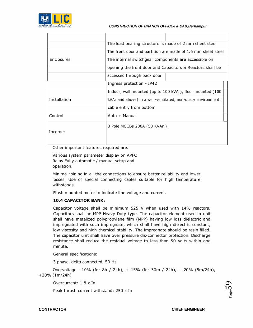
CONSTRUCTION OF BRANCH OFFICE-I & CAB,Berhampur
CONTRACTOR CHIEF ENGINEER
Pa
ge5
9
The load bearing structure is made of 2 mm sheet steel
Enclosures
The front door and partition are made of 1.6 mm sheet steel
The internal switchgear components are accessible on
opening the front door and Capacitors & Reactors shall be
accessed through back door
Ingress protection - IP42
Installation
Indoor, wall mounted (up to 100 kVAr), floor mounted (100
kVAr and above) in a well-ventilated, non-dusty environment,
cable entry from bottom
Control Auto + Manual
Incomer
3 Pole MCCBs 200A (50 KVAr ) ,
Other important features required are:
Various system parameter display on APFC
Relay Fully automatic / manual setup and
operation.
Minimal joining in all the connections to ensure better reliability and lower
losses. Use of special connecting cables suitable for high temperature
withstands.
Flush mounted meter to indicate line voltage and current.
10.4 CAPACITOR BANK:
Capacitor voltage shall be minimum 525 V when used with 14% reactors.
Capacitors shall be MPP Heavy Duty type. The capacitor element used in unit
shall have metalized polypropylene film (MPP) having low loss dielectric and
impregnated with such impregnate, which shall have high dielectric constant,
low viscosity and high chemical stability. The impregnate should be resin filled.
The capacitor unit shall have over pressure dis-connector protection. Discharge
resistance shall reduce the residual voltage to less than 50 volts within one
minute.
General specifications:
3 phase, delta connected, 50 Hz
Overvoltage +10% (for 8h / 24h), + 15% (for 30m / 24h), + 20% (5m/24h),
+30% (1m/24h)
Overcurrent: 1.8 x In
Peak Inrush current withstand: 250 x In

CONSTRUCTION OF BRANCH OFFICE-I & CAB,Berhampur
CONTRACTOR CHIEF ENGINEER
Pa
ge6
0
Total watt-losses: < 0.45 W / kVAr
Temperature category: -25° C to 55° C 6000 switching operations per
year
IEC 60831
10.2 DETUNED FILTER
Detuned harmonic filter reactors shall be used along with power capacitors to
mitigate harmonics amplification and to avoid electrical resonance in LV
electrical networks.
The complete unit shall be impregnated under vacuum and over-pressure in
impregnation resin. The insulation shall be Class H.
The reactors shall be made of high grade aluminum windings, having a three
phase, iron core construction suitable for indoor use. The reactor shall be air
cooled and the layout shall be in accordance with IEC 60289 / IS 5553.
The permitted tolerance of inductance is ± 3% of rated inductance value.
Reactor tuning factor shall be 7 % (189 Hz) and the current rating of the
reactor shall include the effects of harmonics and other possible over-currents
The limit of linearity of inductance of the filter reactor is: 1.8*In with L=0.95*LN.
The reactor shall be fitted with a temperature sensitive micro-switch in the
center coil (normally open) for connection to trip circuits in case of high
operating temperatures.
Power loss in each reactor shall be less than 5 W/kVAr
Each reactor shall have routine test certificate for the above tests.
Contactor
All contactors shall be AC6B duty 3 pole air-break, magnetic, capacitor duty type.
The rating of contactor shall be suitably assigned. The contactors shall be so
chosen as to withstand inrush current due to parallel switching. Contactor should
be with damping resistors to limit capacitor charging current
The individual capacitor bank/step shall be switched automatically/ manually with
selector switch as required using magnetic contactors suitable for switching
capacitive currents. The contactor coil voltage shall be as specified. The minimum
life expectancy of the contactor shall be one million switching operations
Contactor should be with surge
suppressor Operation voltage up to
690V
Insulation voltage 1 kV
Rated impulse withstand up to 8 kV
10.5 APFC Controller
The APFC controller should be microprocessor based and should correct power
factor with the help of contactors by switching the required no. capacitor banks.

CONSTRUCTION OF BRANCH OFFICE-I & CAB,Berhampur
CONTRACTOR CHIEF ENGINEER
Pa
ge6
1
The controller should offer power factor correction without any need for manual
intervention. The controllers should decide optimum configuration of capacitor
banks in order to achieve desired power factor by taking into consideration the
kVAr of each step, no of operations, total usage time, re- connection time of each
step etc. Besides manual switching of capacitors should also be possible directly
through the controller, The APFC controller should have the following basic
features.
Backlit LCD display with multiple parameters displayed at the
same time Auto step programmable
Capable of measuring VTHD and ITHD values at least up to 15th order
Automatic CT reversal sensing and correction Should be 1A / 5A CT
selectable.
Sensing shall be done at LT as well as HT side of the
transformer Display of average weekly power factor
Keypad lock feature to prevent operation by unauthorized persons
Alarms for under/over compensation, high VTHD/ITHD, over temperature,
capacitor failure, capacitor over-current, over/under voltage
Individual capacitor’s ON/OFF status and capacitor failure
indication Temperature sensing feature with alarm in case of
panel over heating Should have RS485 communication
protocol.
10.6 ENCLOSURE
The panel shall be indoor type, free standing, and floor mounting with IP42
degree of protection. It shall be completely made of CRCA sheet steel. The
enclosure shall have sturdy support structure with angle supports as necessary
and shall be finished with powder coating in the approved colour shade/s to
match the colour of the other panels. The thickness of powder coating should be
minimum 60-80 microns.
Suitable provisions shall be made in the panel for proper heat dissipation. Air
aspiration louvers for heat dissipation shall be provided as a necessary.
The front portion shall house the switchgear and the rear portion shall house
capacitors and series reactors. The enclosure is to be suitably sized to
accommodate all the components, providing necessary air clearance between live
and non-live parts, providing necessary working clearance.
10.7 SWITCHGEAR & PROTECTION
Incomer switchgear shall be TP&N breaker appropriate rating. Suitable contactor
for each step shall be used and must be capable of capacitor switching duty at
each step for short circuit protection.
Bus bars shall be suitably colour coded and must be mounted on appropriate
insulator supports.
CONSTRUCTION OF BRANCH OFFICE-I & CAB,Berhampur
CONTRACTOR CHIEF ENGINEER
Pa
ge6
2
Power cables used shall have superior mechanical, electrical and thermal
properties, and shall have the capability to continuously operate at very high
temperatures up to 125 deg.C.
Internal wiring between main bus-bars, breaker, contactor and capacitors shall be
made with 1100 V grade, PVC insulated, copper conductor cable of appropriate
size, by using suitable copper crimping terminal ends etc.
Suitable bus links for input supply cable termination shall be provided.
10.8 CONTROL CIRCUIT & GENERAL PROTECTION
The control circuit shall be duly protected by using suitable rating MCB.
An emergency stop push button shall be provided to trip the entire system (22.5
mm dia, mushroom type, press to stop and turn to reset).
Wiring of the control circuit shall be done by using 1.5 sq.mm, 1100 V grade, PVC
insulated, multi-stranded copper control wire.
Inspection terminal strip, number ferruling, labeling etc. shall be provided.
440 V caution board on the panel shall be provided.
11.0 EARTHING SYSTEM
11.1 GENERAL
11.1.1 Work Description
This section covers design, and setting of the complete earthing network for
individual earthing systems, circuit protective conductors and bonding conductors
and, supply, installation, testing, commissioning of earthing system.
A complete earthing network comprising cables, copper tapes, electrodes and
earth bonding of all relevant necessary non-current carrying metal parts of
equipments/ apparatus shall be connected as required.
The system shall have a common earthing system as described in the
specification and as shown on the drawings. Individual earthing systems as per
drawing shall be provided for following:
• LT Electrical Earthing ( 2 No. GI plate earthing)
• Earthings for Lifts.( 2 No. GI plate earthing)
• Earthing Domestic water pumps. ( 1 No. GI pipe earthing)
• Earthing for Lightening Protection.
• ELV Earthing ( 1 No. GI pipe earthing)
• Data Communication Earthing( 1 No. GI pipe earthing)
• UPS ( 1 No. copper plate earthing)
The Contractor shall have approval of materials from engineer-in-charge before
use on work. Execution of earthing shall be carried out only in the presence of the
Engineer or the representative.

CONSTRUCTION OF BRANCH OFFICE-I & CAB,Berhampur
CONTRACTOR CHIEF ENGINEER
Pa
ge6
3
11.1.2 Standards
Complete earthing system shall be designed and executed in accordance with the
latest revision of the following standards and the appropriate BS/IEC:
1. IS: 3043 : Earthing
2. BS6651 : Lightning Protection System
3. IEC 61024-1-2 : Lightning Protection System
The detail of the Earthing System shall also conform to the requirements of all
relevant
local codes as applicable together with the additional requirements referred to in
the
Specification and Drawings, whichever is the more stringent and acceptable to
the Engineer-in charge.
11.1.3 Submission
All technical submissions shall be approved by the EPC contractor prior to the
respective stages of construction with respect to the approved design and
development documents. In case of major deviations, it shall be brought under
the notice of LICI for its review and approval.
As minimum requirement the submission shall include the following:
• Shop Drawings and Sample Submission
• Builder’s work requirement
• Testing procedures and report format for testing of the earth electrodes
and/or earth strips
• Soil resisting test report with calculation report for the details of the earthing
system detail including quantity and layout of earth electrodes and/or earth
strips to achieve the required earth resistance. The report shall be endorsed
by the Contractor’s Installation Engineer who supervise and endorse the
installation upon completion
• Proposed details of earthing system including quantity and layout of the earth
electrodes and/or earth strips according to the calculation result.
11.2 PRODUCT
11.2.1 General
The resistance between earthing system and the general mass of earth shall not
be greater than 1 ohm.
The earth loop resistance to any point in the electrical system shall not be in
excess of 0.5 ohms in order to ensure satisfactory operation of protective devices.
The resistance to earth shall be measured at the following:-
At each electrical system ground or system neutral ground.
At one point each grounding system used to ground electrical equipment
enclosures.

CONSTRUCTION OF BRANCH OFFICE-I & CAB,Berhampur
CONTRACTOR CHIEF ENGINEER
Pa
ge6
4
At one point each grounding system used to ground wiring system enclosures
such as metal conduits and cable sheaths or armoured.
All earthing conductors shall be of high conductivity copper/ G.I. and able to
protect against mechanical damage as per requirement. The cross-sectional area
of earth conductor shall not be smaller than half that of the largest current
carrying conductor. However, the contractor shall use the sizes specified of the
Tender. Common earth mats of resistivity of less than one (1) ohm shall be
constructed below the lowest floor structure prior to any ground work
construction. The earth mats shall comprise the complete earth electrodes, earth
strips/grids, earth inspection chambers, earth leads, main earth terminals, earth
test link boxes at ground level, etc. Each individual earthing system shall have
earth leads connecting its main earth terminal directly to an earth electrode
underground as specified.
All earthing products/accessories shall be in accordance to IS standards.
The mating surface of all tapes at joints etc shall be cleaned before clamping and
riveted with proper connector or exothermic welded. All connections to electrical
apparatus shall be made by bolted connection in a visible and accessible position
11.2.2 Pipe Earth Electrode
G.I. pipe shall be of medium class 100mm dia and 3m in length.
G.I. Pipe electrode shall be cut tapered at bottom and provided with holes of
12mm dia drilled not less than 7.5cm from each other up to 2m of length from
bottom.
The electrode shall be buried in the ground vertically with its top being 20cm
minimum below ground level.
Clamping of the earth leads to the earth rod shall be made by earth clamp. The
clamps shall be capable of providing high pressure contact between the earth rod
and the earth leads to achieve low contact resistance.
When two or more electrodes are driven to form a group, the heads of the
electrodes in the group shall be bonded to each other by means of a 25 mm x
3mm GI / Copper strip, laid at a depth of at least 600 mm in soil.
Recommended water seal insert sleeve approved by Engineer-in-charge shall be
provided with all earth electrode penetrations through basement water proofing
membranes and the installation shall be done under strict supervision.
11.2.3 Plate Earth Electrode
The plate earth electrode shall consist of copper plate or G.I. plate as per item of
work. The plate electrode shall be buried in ground with its faces vertical and top
not less than 4.5m below Ground level. The plate shall be filled with charcoal dust
and common salt filling, extending 15cm around it’s on all sides.
A watering pipe of 50mm dia of medium class G.I pipe shall be provided.
The top of the pipe shall be provided with a funnel and a G.I. mesh screen for
watering the earth. In the case of pipe electrode a removable plug shall be
provided.

CONSTRUCTION OF BRANCH OFFICE-I & CAB,Berhampur
CONTRACTOR CHIEF ENGINEER
Pa
ge6
5
The earthing lead from electrode onwards shall be suitably protected from
mechanical injury by suitable dia medium class G.I. pipe in case of wire and size
according to strip size.The overlapping of strips at joints shall done in approved
manner
GI strips shall be riveted with rivets/ bolted and welded.
• Copper strips shall be riveted with rivets/ bolted brass nuts, bolts and
washers and brazed.
The protection pipe within ground shall be buried at least 30 cm deep (to be
increased to 60cm in case of road crossing and pavements).
The portion within the building shall be recessed in walls and floors to adequate
depth.
In the case of plate earth electrode the earthing lead shall be securely bolted to
the plate with two bolts, nuts, check nuts and washers.
In case of pipe electrode it shall be connected by means of a through bolt, nuts
and washers and cable socket.
Main earthing conductor is taken from the earth electrode with which the
connection is to be made.
No earth pit shall be fixed within 1.5 M of a wall of foundation. The location of the
earth electrode will be such where the soil has reasonable chance of remaining
moist. Effort shall be made to locate them in grass lawns or near flower beds or
water taps.
11.2.4 Earth Inspection Chamber
Earth electrode shall be fitted with a heavy-duty pre cast concrete inspection
chamber / pit complete with heavy-duty cover as specified on drawings.
For earth electrodes located outside or on the apron of the building, earth
inspection chambers shall extend to a depth of not less than 300 mm below
finished ground level and kept free of soil. For earth electrodes located inside
building, earth electrodes shall be buried not less than 100 mm below the floor
slab structure. Each earth electrode shall be clearly marked ‘Safety Electrical
Earth Connection – Do Not Remove’.
The chamber and cover shall be heavy duty detail to consider the traffic load at
the location of installation. The cover shall be recessed cover to receive the
Architectural floor finish at the location of installation.
11.2.5 Earth Strip
Earth strips/grids shall be of bare GI/ Copper strips of 25 mm x 3 mm as
specified.
Earth strips shall be riveted or joint with proper connector to earth electrodes
underground below the floor slab structure, and shall be buried not less than 300
mm below the floor slab structure.
In order to minimize the mutual inductance between strips, earth strips shall be
positioned at a distance not less than 6m apart unless otherwise specified.
CONSTRUCTION OF BRANCH OFFICE-I & CAB,Berhampur
CONTRACTOR CHIEF ENGINEER
Pa
ge6
6
11.3 EARTH BONDING
11.3.1 Circuit Protective Conductor
Circuit protective conductor (CPC) is a system of conductors joining together all
exposed conductive parts and connecting them to the main earth terminal.
The purpose of circuit protective conductor is to provide a path for earth fault
circuit so that the protective device will operate to remove dangerous potential
differences during a fault condition.
The circuit protective conductors shall take the form of separate cable with a
sheath in green/yellow color or copper tape of minimum size 25mm x 3mm.
All exposed non-current carrying metal parts of light fittings, switchgears,
motors, enclosures, etc. shall be effectively earthed by circuit protective
conductors for earth continuity protection.
For equipment where an earth terminal is provided, the earth continuity wire shall
be firmly clamped. Where no earth terminal is provided, the exposed metal part
shall be cleaned of paint and surface rust before welding the earth continuity
lead.
The minimum size of the principal protective conductors shall be in accordance
with to the current edition of IS: 3043/ BS7671 and BS7430.
The external earth terminal on the outside of the end panel of any switchboard
shall be connected to the main earth bar provided in two independent points.
Circuit protective conductors shall be provided in electrical and mechanical rooms
and along the routes for the bonding of all exposed conductive parts and
extraneous conductive parts. A suitably sized earth terminal shall be provided at
each zone of the building for this purpose.
All exposed conductive parts shall be effectively connected in an approved
manner to the principal protective conductors. The circuit protective conductors
shall be single core copper cables or high conductivity annealed copper tapes
specified. Unless otherwise specified, the minimum cross-sectional area of the
circuit protective conductors shall be selected in accordance with IS: 3043/
BS7671.
12. Deleted.
13 : SUBSTATION ACCESSORIES

CONSTRUCTION OF BRANCH OFFICE-I & CAB,Berhampur
CONTRACTOR CHIEF ENGINEER
Pa
ge6
7
13.0 GENERAL:
13.1 Danger Sign boards
The Danger notice labels shall be made on indestructible non deteriorating material with
lettering engraved in red, black, white background except where otherwise specified. The
letters shall be at least of 12 MM and shall be of radium sticker type so as to be visible in
the night time also.
13.2 M. S. Chequared Plates :
The plates shall be as specified in the item and shall have 3 coats of anti corrosive paint.
The plates shall not be brittle and shall take normal weights.
13.3 Rubber mats and hand gloves
Rubber insulation gmats conforming to IS 15652-2006 shall be provided in front of main
switch board as well as other control equipments as specified in drawings. Rubber mats,
Rubber gloves, boots shall confirm to the safety equipments standard and shall with ISI
approval.
13.4 First aid kit and First aid shock treatment charts
Charts (One in English, one in hindi and one in regional language), displaying methods of
giving artificial respiration to a recipient of electrical shokc shall be prominently provided
at appropriate place. Standard first aid boxes contanining materials for first aid shall be
provided in sub-station.
13.5 Fire Extinguishers
Portable Co2 conforming to IS : 2878-1976 fire extinguishers shall be installed in the sub
station at suitable places as per the fire safety norms.
13.6 Fire buckets
Fire buckets conforming to IS: 2546-1974 shall be installed with the suitable stand for
storage of water and sand as per the fire safety norms.
13.7 Deleted
13.8 Safety Equipments (Rubber mats, rubber gloves, First aid kit, Sign boards,
Sand Buckets, Fire Extinguishers etc.)
The Danger notice labels shall be made on indestructible non deteriorating material with
lettering engraved in red, black, white background except where otherwise specified. The
letters shall be atleast of 12 MM and shall be of radium sticker type so as to be visible in
the night time also.
Rubber mats, Rubber gloves, boots shall confirm to the safety equipments standard and
shall with ISI approval.
Sand Buckets and Fire extinguishers shall be as per the fire safety norms and shall be
operated as specified in the item.
Emergency lights shall be with maintenance free rechargeable batteries.
14.0 LIGHTNING PROTECTION SYSTEM
CONSTRUCTION OF BRANCH OFFICE-I & CAB,Berhampur
CONTRACTOR CHIEF ENGINEER
Pa
ge6
8
14.1 WORK DESCRIPTION
This section comprises the engineering, supply and installation, testing necessary
for the Lightning Protection System for all buildings and of open areas (storage,
leisure, office areas etc) It includes the protection against the electrical
consequences due to the lightning current flow through the lightning protection
system.
Notes:
• This standard does not cover the protection of electrical equipments or
system against voltage surges of atmospheric origin which are transmitted by
networks entering the structure.
• Other standards describe lightning protection systems using simple rod
lightning conductor, stretched wires and meshed conductors.
The Lightning Protection System shall be installed generally in accordance with IS
/ IEC 62305- 3 & IS 3043 and additional requirements of this specification. The
system shall consist of air terminations, down conductors, joints and bonds,
testing joints, earth terminations and earth electrodes. The general arrangement
shall be as indicated on the drawings.
The lightning protection system shall comprise:-
• Air terminal (as per rolling sphere or mesh or protective angle method or any
combination thereof.)
• Down Conductors
• Joints and Bonds
• Test Links
• Maintenance free earthing system based on chemical earth compound
Lightning protection system employing steel structural and reinforcement system
as part of the down conductors shall be adopted as per Drawing specified. All
requirements in the specification included cast-in re-bar down conductors shall be
applied unless otherwise specified.
14.2 STANDARDS
Complete supply and installation of the lightning protection system shall be
followed for engineering, construction and installation in accordance of the
following standards and with the latest revision with update amendments:
IS / IEC 62305-3 & IS 3043 IS/ IEC 62561
The detail of the lightning protection system shall also conform to the
requirements of all relevant local codes, as applicable, together with the
additional requirements referred to in this Specification and Drawings, whichever
is the more stringent and acceptable to the Engineer.
In the adoption of standards and requirements, the Contractor shall take the
following precedence:
• Engineer’s decision
CONSTRUCTION OF BRANCH OFFICE-I & CAB,Berhampur
CONTRACTOR CHIEF ENGINEER
Pa
ge6
9
• Local codes of practice
• Drawings
• Specification
• International standards and requirements.
• Lightning arrestor air terminals Lightning and Earthing Material
14.3 SUBMISSION
All technical submissions shall be got approved by the EPC contractor prior to
the respective stages of construction with respect to the approved design and
development documents. In case of major deviations, it shall be brought
under the notice of LICI for its review and approval.
A prior survey may be conducted to determine the protection level to be
considered, the ESE lightning conductor location(s), the down –conductor
path(s), the earth termination system location(s) and type(s). All technical
submissions shall be approved by the Engineer prior to the respective stages
of construction.
Architectural constrains may be taken into account in the lightning protection
system design and the design shall be based in a manner so that there is no
reduction in the lightning protection system effectiveness.
As a minimum requirement, the submission shall include the following:
• Equipment submission with manufacturer’s data;
• Sample submission;
• Shop Drawings showing the co-ordinate routing of air terminations, down
conductors bonding to re-bar and foundation earth terminations, methods
of fixing etc.
• Builder’s works requirement.
• Proposal on testing procedures and report format for testing of the
Lightning Protection System.
• Detail of the Contractor’s installation Professional Engineer who supervise
and endorse the installation for occupation permit application.
14.4 AIR TERMINAL
1.0 General
Lightning Protection System shall be in accordance with IS / IEC 62305-
3 & IS 3043 2.0 Zone of Protection
The zone of protection of a lightning conductor defines the space within which Air
Terminal provides protection against a direct lightning strike with probability of
protection as per LPL.
2.0 LPL (Lightning Protection Level)

CONSTRUCTION OF BRANCH OFFICE-I & CAB,Berhampur
CONTRACTOR CHIEF ENGINEER
Pa
ge7
0
LPL is a number associated with a set of lightning current parameters relevant to
the probability that the associated minimum & maximum values do not exceed
the normally occurring lightning. LPL can be determined by Risk analysis as
explained in IS / IEC 62305-2.
Components of External LPS
1.) Air terminal (as per rolling sphere or mesh or protective angle method or any
combination thereof.)
2.) Down conductor
3.) Earthing
2.1 Air termination system:
No drilling is allowed in the terrace for fixing the air terminal, if the roof is
made of concrete. Parapet wall is exception to this.
2.1.1 Material and Dimensions
Material of air terminal, down conductor, earth termination etc. shall be as below:
Material May be destroyed by galvanic coupling
with
Copper(Solid) GI and Aluminium
Hot galvanized steel(Solid) Copper
Stainless steel(Solid) ………
Aluminium (Solid) Copper
Dissimilar metals (eg. Copper with Aluminium) must be connected only by using
bimetal connectors.
Minimum thickness of metal in air termination system for LPL /LPS
Material Thickness (a) in mm Thickness (b) in mm
Galvanized steel 4 0.5
Stainless steel 4 0.5

CONSTRUCTION OF BRANCH OFFICE-I & CAB,Berhampur
CONTRACTOR CHIEF ENGINEER
Pa
ge7
1
Copper 5 0.5
Aluminium 7 0.65
Material, Configuration and Minimum cross sectional area of air terminal &
down conductors
Minimum
Material Type cross section Remarks
area
Copper Solid tape 50 sq mm 2mm min thickness
Copper Solid round 50 sq mm 8mm dia
Aluminum Solid tape 70 sq mm 3 mm min thickness
Aluminium Solid round 50 sq mm 8 mm dia
GI Solid tape 50 sq mm 2.5 mm min thickness
Stainless steel Solid tape 50 sq mm 2 mm min thickness
2.1.2 Air terminal holder:
Concrete Roof structure: Conductors shall be securely fixed on the terrace
by means of air terminal holder which is fixed on the roof by adhesive of
good quality taking care of varying weather conditions. Air conductor holder
is an insulator & should be of minimum 50 mm height so that even small
amount of water logging on terrace is below the level of conductor holder.
Metal Roof structure: Conductors shall be securely fixed on the terrace by
means of air terminal holder which is fixed on the roof by metal conductor
holder of good quality which is tested for lightning current as per IEC
standard. Vendor need to give proof. As metal roof structures are normally
tapered at an angle, there is no min. height criteria for metal conductor
holder.

CONSTRUCTION OF BRANCH OFFICE-I & CAB,Berhampur
CONTRACTOR CHIEF ENGINEER
Pa
ge7
2
2.1.3 Recommended distance between air terminal holders:
Recommended
Recommended distance
Arrangement distance for
For ROUND conductors
SOLID TAPE
Horizontal conductor on horizontal surface 500 mm 1000 mm
Horizontal conductor on vertical surface 500 mm 1000 mm
Vertical conductor from Ground to 20m 1000 mm 1000 mm
height
Vertical conductor above 20m height 500 mm 1000 mm
If antenna, air cooler or any other electrical equipment is present above terrace
level, the same have to be protected by using vertical air terminal after
calculating the safety or separation distance. The vertical air terminal has to have
suitable supports to hold it
Wind speed need to be taken into account. Vertical air terminal must be
connected to horizontal air terminal by using suitable connectors.
t the crossings of the horizontal air terminals, suitable Cross connector has to be
used for secure connection which is tested for lightning current as per IEC
standard. Vendor has to provide proof.
2.1.4 Safety or Separation distance:
It is must to calculate safety or separation distance in order to avoid flash over to
the electrical equipment when the lightning current is passing through the
vertical air terminal.
2.1.5 Safety/Separation distance (S) in m = (ki * kc*L) / km
Coefficient ki depends on class of LPL/LPS
ki = 0.08 for LPL1,
ki = 0.06 for LPL 2,
ki = 0.04 for LPL3 and 4.
Coefficient kc depends on no of down conductors:
kc = 0.66 for 2 down conductors
kc = 0.44 for 3 or more down conductors
Value of coefficient km = 1
Value of L is the total distance between the equipment to be protected (for e.g.
Antenna) to the equi-potential bonding bar situated just above the ground.

CONSTRUCTION OF BRANCH OFFICE-I & CAB,Berhampur
CONTRACTOR CHIEF ENGINEER
Pa
ge7
3
2.1.6 Expansion piece
In order to take care the expansion of the metal in summer and contraction of
the metal in winter, expansion piece with suitable connectors have to be used at
every 20m distance of horizontal air terminal.
2.1.7 Joints and Bonds
The lightning protective system shall have few joints as far as possible & air
terminal & down conductor have to be straight. Where it is not possible, it should
NOT be bent at 90 degree (right angles) & should have a curved path of 45
degree bend.
2.1.8 Down conductor system
In order to reduce the probability of damage to electronic/electrical equipment,
the down conductors shall be arranged in equal distance in such a way that from
the point of strike to earth, several parallel current paths should exist & length of
the current path should be minimum. Down conductors can be installed
separately or more wisely it can be part of natural components of the building.
Examples are steel reinforcement in RCC columns, metal facades, profile rails,
metal doors & windows. Down conductors should be installed at each exposed
corner of the structure as a minimum.
Value of distance between down conductors as per Class of LPL / LPS
Class of LPL/LPS Typical distance (m)
1 10
2 10
3 15
4 20
2.2.1 Test joints:
At the connection of the earth terminal, a test joint should be fitted on each down
conductor at a height of 1 m from the ground, except in the case of natural down
conductors combined with foundation earth electrode. The purpose of test joint is
to measure the earth resistance value. The remaining portion of down conductor
(i.e., after the test joint should be mounted inside a plastic pipe of minimum 3
mm thickness.)
2.2.2 Earth Terminations
Earth mat is most preferable. Where earth mat is not possible, ring earthing is
the next best method. Ring earthing must be 1 meter away from the building
and 0.5m below the ground level. The resistance of earthing system shall not
exceed 10 ohm as per IEC 62305. Lower earth resistance is more preferable
For earth termination system, 2 basic types of earth electrode arrangements
are applicable.
Type A & Type B arrangement.

CONSTRUCTION OF BRANCH OFFICE-I & CAB,Berhampur
CONTRACTOR CHIEF ENGINEER
Pa
ge7
4
Type A arrangement: Comprises of horizontal or vertical earth electrode installed
outside the structure to be protected connected to each down conductor.
In type A arrangement, the total number of earth electrodes shall not be less
than two.
Type A arrangement is suitable in places where electronic equipment are not
located.
Type B arrangement: This type of arrangement comprises either a ring conductor
external to the structure to be protected, in contact with the soil for at least 80%
of its total length or a foundation earth electrode. Such earth electrodes can also
be meshed. For structures with extensive electronic systems or with high risk of
fire, type B earthing is most preferable method. Corrosion proofing band has to
be used wherever down conductor is connected to earth termination system.
Bitumen has to be applied at the point of inter-connection.
In potentially corrosive areas, Stainless steel must be used.
LIGHTNING PROTECTION
• The lightning protection system shall not be in direct contact with underground
metallic service ducts and cab.
• Conductors of the lightning protection system shall not be connected with the
conductors of the safety earthing system above ground level.
• Down conductors shall be cleated on the structures at 600 mm interval.
• Connection between each down conductor and rod electrodes shall be made via
test joint (pad type compression clamp) located approximately 1500 mm above
ground level. The rod electrode shall be further joined with the main earth mat.
Lightning conductors shall not pass through or run inside G.I. conduits
2.2.3 References:
IS / IEC62305 – PROTECTION AGAINST LIGHTNING:
Part 1: General Principles
Part 2: Risk Management
Part 3: Protection of structures
Part 4: Protection of Electrical & Electronic equipment within structure
IS3043: 1987: Code of practice for Earthing.
TESTING & COMMISSIONING
The contractor shall conduct his own inspection and test reports certified by their
engineer shall be submitted to the Engineer-in-charge for his approval and submit
a request for joint inspection.
Joint inspection shall be carried out by the engineer-in charge or his authorized
representative. Test results shall be checked and compared with the report
submitted. All equipment, transportation, manpower and other necessary costs
for the joint inspection shall be borne by contractor.
The system shall be tested once in every month intervals for earth resistivity,
resistance to earth of the electrodes and electrical continuity of the system. The

CONSTRUCTION OF BRANCH OFFICE-I & CAB,Berhampur
CONTRACTOR CHIEF ENGINEER
Pa
ge7
5
record of readings / results of these tests shall be maintained by contactor during
defect liability period by the contractor and after that by Engineer-in charge.
The contractor shall supply one set of potable Air terminal test meter suitable for
operation on batteries for maintenance and check of system. The meter should be
suitable:
To test the individual charge sensor
To test the individual triggering
terminal To identify the faulty air
terminal
To give alarm in case test meter is defective.
The Contractor shall submit a detailed layout drawing showing the positions of
testing carry out on site.
15.0 EXTERNAL LIGHTING
15.1 WORK DESCRIPTION
The scope of work includes for the external lighting indicates approximate position
of all lighting fittings. The actual position of all fittings, the wiring details and
cable routes shall be co-ordinated with other trades at site and submitted for the
approval of the Engineer-in-charge. All time and cost required for adjusting the
layout or complete installation to suit site requirement is included.
To determine the exact positioning of External lighting points due consideration
shall be given, for selection of the most accessible routes for wiring, convenience
of switching and operational requirement of the installation.
No extra cost will be paid should the final positions be relocated.
For the purpose of specification and related drawing, each lighting circuit shall be
coded with a prefix to indicate the corresponding distribution board number.
The electrical equipment/system may develop sudden changes due to low
frequency/or direct electric current components such as fluorescent lamps,
contactors, etc. shall be fitted with radio and television interference suppression
components suitable to meet the levels specified in BS 800 “Limits of Radio
Interference”.
15.2 STANDARDS
The complete wiring installation shall be engineered according to manufacturer
data and constructed in accordance with the latest revision of the IS and the
appropriate BS/IEC In the adoption of standards and requirements, the
Contractor shall take the following precedence:
Engineer’s decision
Local codes of
practice Drawings
Specification
International standards and requirements

CONSTRUCTION OF BRANCH OFFICE-I & CAB,Berhampur
CONTRACTOR CHIEF ENGINEER
Pa
ge7
6
15.3 SUBMISSION
All technical submissions shall be approved by the EPC contractor prior to the
respective stages of construction with respect to the approved design and
development documents. In case of major deviations, it shall be brought under
the notice of LICI for its review and approval.
The submission shall include the following as a minimum requirement, Equipment
catalogues submission with manufacturer’s data Sample submission include all
wiring accessories Shop Drawings of the lighting, circuit numbers, cable routings,
switching arrangement, mounting height, etc. The positions and mounting heights
shall be coordinated with other services. Fixing details of all wiring accessories
shall also be included. Drawings showing the installation details Labeling system
Builder’s works requirement.
b. PRODUCT
15.4 EXTERNAL LIGHTING:
Street Light : Suitable Street light ( not less than 18 W LED) and Light pole made out of
50mm dia B class GI pipe. The total length of the pole being 5 Meter with MS base plate
of size 300 x 300 x 12mm welded at the bottom of the post is to be grouted 900mm
below ground level in concrete (1:2:4) mixture & providing concrete pedestal of 300mm
dia of 600mm height above the ground level duly plastered and painted with white
colour. weather proof FRP Junction box is to be provided with 6amp SPMCB & neutral
link connector on the pole with proper clamps. Pole is to be coated with one coat of red
oxide and two coats of silver paint. A suitable size of bracket made out of B class GI pipe
to suit the installation of fitting is to be provided on top of the post, which is also to be
painted and clamped properly to take the load of the fitting. The lead wires from
Junction box to the fitting are also to be provided by means of 3x1.5 sqmm armoured
copper pvc insulated cable. G.I. pipe of B class of suitable size is to be provided in the
pedestal for protection of cable up to the Junction box with necessary bend.
Gate Light : Suitable decorative lights ( not less than 18 W LED Light) with suitable
length of class B GI pipe of appropriate diameter compatible with the fitting for its
mounting suitably grounded in gate pillar. Whether proof junction box in the pillar
comprising and including 6 A/10 A SP MCB and Bakelite connector. Wiring from Whether
proof junction box by means of 3x1.5 sqmm pvc insulated frls copper wire in MS conduit.
The Lux level for lighting shall be considered as per IS standards and on the following
area requirement.
Parking 150
Internal Roads 150
CONSTRUCTION OF BRANCH OFFICE-I & CAB,Berhampur
CONTRACTOR CHIEF ENGINEER
Pa
ge7
7
External lighting
Street light has to be provided along the road work as below:
1 External Periphery LED Street light fitting on 4.5 mtr 50 mm Dia
G.I. Pipe lamp post. ( not less than 18 W LED
Light) and minimum 3 Nos. 9 watt solar
street light
LED street light fittings with 25 mm Dia G.I.
pipe bracket on external wall of Building ( not
less than 18 W LED Light)
2 Gate pillars Suitable decorative lights ( not less than 18
W LED Light)
16.0 FINAL DISTRIBUTION BOARDS & DEVICES:
16.1 GENERAL
This section covers specification of DBs.
16.2 STANDARDS AND CODES
The latest and amended upto date Indian Standard Specifications and Codes of
Practice will apply to the equipment and the work covered by the scope of this
contract. In addition the relevant clauses of the Indian Electricity Act 1910 and
Indian Electricity Rules 1956 as amended upto date shall also apply. Wherever
appropriate Indian Standards are not available, relevant British and/or IEC
Standards shall be applicable.
16.3 MINIATURE CIRCUIT BREAKERS & RESIDUAL CONTROL DEVICES
Miniature circuit breakers shall be of approved design and make and must be
tested and validated as per IS/IEC 60898 and IEC 60947-2 standards.
MCBs shall be suitable for operation at 240V/415V, 50Hz supply. The MCB
ratings shall be available from 10-40A in 1P/2P/3P/4P versions. The rated short
circuit capacity shall be 10KA as per IS/IEC 60898 and electrical life shall be
10,000 operations. MCBs shall be offered with B, C or D tripping characteristics
as per the requirements. The MCBs shall be suitable for mounting on a 35mm
DIN rail.
MCBs shall carry ISI and CE marking. The MCB manufacturer (through the
bidder) has to submit the valid BIS license certificate at the time of offer
submission.
MCBs shall ensure complete electrical Isolation of downstream circuit or
equipment, when the MCB is switched OFF (to be marked on the MCB in symbolic
form)
IP 20 Degree of Protection shall be ensured to prevent electrical shocks by
accidental touch to any live parts, by providing finger touch proof terminals.
Energy Limitation Class-3 shall be to ensure minimum let through energy in the
event of a fault, for safety & longevity of downstream circuit equipment. (to be

CONSTRUCTION OF BRANCH OFFICE-I & CAB,Berhampur
CONTRACTOR CHIEF ENGINEER
Pa
ge7
8
mentioned on the as per standards ) MCBs shall be line-load reversible with no
derating @ 35 deg C.
MCBs shall have bi-connect facility to terminate fork type busbar and wires,
simultaneously. Terminal capacity shall be minimum 25 sq.mm. for ratings up to
25A, and 35 sq.mm. for ratings 32A & above to ensure perfect termination of
wires and cables. Terminals of MCBs shall have captive screws.
Basic technical parameters, rating, operating voltage, energy limiting class 3 etc.
shall be printed on front face of MCB for ease of identification. MCB should have
clear indication on front facia for tripping on Short circuit faults for differentiation
between O/L & S/C faults
The devices must be capable of heavy-duty operation and to that end, the
manufacturer shall guarantee the following performance levels, defined by IEC /
EN 60947-2 standards:
• suitability for isolation (section 7.2.7)
• rated insulation voltage (section 4.3.1.2): 500 V
• pollution degree (Part 1, section 6.1.3.2): 3
• rated impulse-withstand voltage (section 4.3.1.3): 6 kV
• Discrimination for power continuity
• Validated Cascading tables as per standard IEC 60947-2
Operating knob shall have provision to lock in ON / OFF condition without
affecting any automatic tripping
Circuit- breakers shall be capable of operation under ambient temperature up to
35 °C, without derating of their overload tripping threshold with respect to their
rated operating current. The same must be tested and validated as per IEC
60947-2 standard.
MCBs shall be suitable for field-fittable Protection auxiliaries (viz. Over-voltage
release, Under -voltage release, Shunt trip) and Indication Auxiliaries (like
Auxiliary Contact, Trip alarm contact).
For critical application feeders wherever specified in for remote monitoring of
circuit breakers status is required, MCB shall be communication ready to indicate
the status of the device (On/Off/Trip), Number of On/Off cycles and Number of
Tripping over universally open Modbus protocol so as to have seamless
connectivity with any Energy and Building Management System.
16.4 RCCB WITH OVER CURRENT PROTECTION (RCBOS): 2 MODULE VERSION
RCBOs must confirm to IEC/EN 61009 standards.
RCBOs shall be suitable for operation at 240V/415V, 50Hz supply. The RCBO
ratings shall be available from 6A-40A in SPN version with the sensitivity of 30mA
(for personal protection) and 300 mA (for Fire protection), as per the
requirements. Rated short circuit breaking capacity shall be 10KA RMS
CONSTRUCTION OF BRANCH OFFICE-I & CAB,Berhampur
CONTRACTOR CHIEF ENGINEER
Pa
ge7
9
RCBO shall have clear separate indication of tripping on Short circuit and earth
leakage faults on front facia. RCBO shall have Electrical life of 10,000 operations
for all ratings.
16.5 DB (DISTRIBUTION BOARD)
Distribution Boards shall be tested as per IEC61439-III standards and have
following features:
Recess/ Surface type with integral loose wire box.
Phase/ neutral/ earth terminal blocks for termination of incoming & outgoing
wires.
Din Channel for mounting MCBs.
Arrangement for mounting incomer MCB/ RCCB/ RCBO/ MCCB as required.
Copper Bus bar
Earthing bolts- 2 nos.
Wiring from MCBs to phase terminal block.
Terminal blocks should be suitable for termination of conductor/ cable of required
size but minimum rated cross section of the terminal blocks should be 6 sq. mm.
Terminal block shall be made of flame retardant polyamide material.
Colour terminal blocks and FRLS wires for easy identification of RYB Phases,
Neutral and Earth.
Prewired DB shall be provided with a detachable PAN assembly for safe removal
of MCBs, RCCBs.
The prewired DB shall have have cement spill protector /masking sheet for
protection from cement, plaster, paints etc. during the construction period.
Detachable plate with Knock out holes shall be provided at the top/ bottom of
board. Complete board shall be factory fabricated and pre-wired in factory ready
for installation at site. The box and cover shall be fabricated from 1.6mm sheet
steel, properly pre-treated with 7 tank process and duly powder coated,
phosphatized with powder coated finish.
DB shall have neutral & earth terminal block on the side, not on top or bottom to
provide better wiring space and hear dissipation inside the DB.
DBs shall be provided with rotary knob and shall have flexibility to change to Key
lock on field.
The Ingress Protection for entire range of DBs must be certified by any neutral
testing authority (viz. ERDA / CPRI/ any govt certified lab) as per standard IS/IEC
60529 for the degree of;
IP43 for DBs for indoor application and IP 54 for outdoor application.
The Impact Protection for entire range of DBs must be certified by any neutral
testing authority (viz. ERDA, CPRI, any govt certified lab ) as per standard IEC
62262 for the degree of : IK09 for DBs with Double Door

CONSTRUCTION OF BRANCH OFFICE-I & CAB,Berhampur
CONTRACTOR CHIEF ENGINEER
Pa
ge8
0
Environmental regulations for Green Buildings : DB shall comply with RoHS and
REACH standard and shall have high Strength-to-Weight ratio to avoid burden on
building structure.
Where specified it shall be of double door construction provided with hinged cover
in the front.
Horizontal TPN DBs shall have Separate Insulated Neutral bar for each phase .
17.0 SPECIFICATIONS FOR LED LIGHT FIXTURES / LUMINAIRES
17.1 SCOPE
The scope of work includes design, testing, supply and commissioning of energy efficient
luminaries complete with all accessories, LED lamps with suitable current control driver
circuit including mounting arrangement for recessed type and ceiling / wall mounting
arrangements.
17.2 STANDARDS
The LED light fixtures / luminaries their associated accessories such as lamps / tubes,
reflector, housings, glass, diffusers, energy efficient ballasts/drives etc. shall comply with
the latest applicable standards.
IS: 16102-2 : Ballast type LED lamp performance requirement, lamp and
accessories
IS: 16107-2-1 : Luminaries performance LED luminaries
IS: 16103-2 : LED modules performance requirements electric lamps and
accessories
IEC 62031 : LED modules for general lighting safety requirements
EN 61547 : Equipment for general lighting purpose EMC immunity
requirement
IEC 60598-2-1 : Fixed general purpose luminaries
IEC 60598-1 : Luminaries General requirement and tests
IEC 61000-3-2 : Electro Magnetic compatibility (EMC) Limits for Harmonic current
emission (equipment input current less than or equal to 16
amps per phase)
IEC 61347-2-13 : Lamp control gear particular requirement or DC and AC supplied
electronic control gear for LED modules
IS: 10322 : Specification or the luminaries
IS: 4905 : Method for random sampling
CONSTRUCTION OF BRANCH OFFICE-I & CAB,Berhampur
CONTRACTOR CHIEF ENGINEER
Pa
ge8
1
LM 79 : LED luminaire photometry measurement
LM 80 : Lumen maintenance
IEC 62384 : DC or AC supplied electronic control gear for LED modules-
performance requirement
IEC / PAS 62612 : Self ballasted LED lamps for general lighting services performance
requirement
17.3 GENERAL REQUIREMENTS
The LED light fixtures / luminaries shall be designed for continuous trouble-free
operation under hot humid atmospheric conditions, at the specified ambient
temperature, without reduction in lamp life or without deterioration of materials and
internal wiring.
The LED light fixtures / luminaries shall be designed so as to facilitate easy maintenance,
including cleaning, replacement of lamps / drives, starters etc.
Connections between different components shall be made in such a way that they will
not work loose by small vibration.
For each type of light fixture the Contractor shall supply the utilisation factor to indicate
the proportion of the light emitted by the bare lamp which falls on the working plane.
The LED light fixtures / luminaries shall be supplied complete with lamps.
The LED light fixtures / luminaries and accessories shall be designed to have low
temperature rise. The temperature rise above the ambient temperature shall be as
indicated in the relevant standards.
17.4 EARTHING
Each light fixture / luminaire shall be provided with an earthing terminal suitable for
connection to the earthing conductor. All metal or metal enclosed parts of the housing
shall be bonded to the earthing terminal so as to ensure satisfactory earth continuity
throughout the fixture.
17.5 PAINTING / FINISH
All surfaces of the fittings shall be thoroughly cleaned and degreased. The fittings shall
be free from scale, rust, sharp edges and burrs. The housing shall be stove-enamelled /
epoxy stove-enamelled / vitreous enamelled or anodised as indicated under various
types of fitting.
17.6 ACCESSORIES FOR LIGHT FIXTURES
REFLECTORS
CONSTRUCTION OF BRANCH OFFICE-I & CAB,Berhampur
CONTRACTOR CHIEF ENGINEER
Pa
ge8
2
The reflectors shall be made of CRCA sheet steel / aluminium / silvered glass as
indicated for above mentioned fittings. The thickness of steel / aluminium shall comply
with relevant standards. Reflectors made of steel shall have stove enamelled / vitreous
enamelled / epoxy coating finish. Aluminium used for reflectors shall be anodized /
epoxy stove enamelled / mirror polished. Reflectors shall be free from scratches or
blisters and shall have a smooth and glossy surface having an optimum light reflecting
co-efficient such as to ensure the overall light output specified by the Manufacturer.
Reflectors shall be easily removable from the housing for cleaning and maintenance
without disturbing the lamps and without the use of tools. They shall be securely fixed to
the housing by means of positive fastening device of captive type.
DRIVES
The ballasts/drives shall be designed, manufactured and supplied in accordance with the
relevant standards. The ballast/drives shall be designed to have a long service life and
low power loss. Ballasts/drives shall be mounted using self locking, anti-vibration fixings
and shall be easy to remove without de-mounting the fittings. They shall be in dust-
tight, non combustible enclosures.
The Ballast/Drive shall be low loss electronic type and suitable to operate at 180V 270V.
End connections shall be brought out in a suitable terminal block, rigidly fixed to the
ballast enclosure. Separate ballast/drive for each lamp shall be provided in case of Multi
Lamp Fittings.
LAMP HOLDERS
Lamp holders, if any shall comply with relevant standards. They shall have low contact
resistance, shall be resistant to wear and shall be suitable for operation at the specified
temperature without deterioration in insulation value. They shall hold the lamps in
position under normal condition of shock and vibration met with in normal installation
and use.
Lamp holders for the LED tubular lamps shall be of the spring loaded bi-pin rotor type,
Live parts of the lamp holder shall not be exposed during insertion or removal of the
lamp or after lamp has been taken out. The lamp holder contacts shall provide adequate
pressure on the lamp cap pins when in working position.
CAPACITORS
The capacitors shall have a constant value of capacitance and shall be connected across
the supply of individual lamp circuits. The capacitors shall be suitable for operation at
supply voltage as specified and shall have a value of capacitance so as to correct the
power factor of its corresponding lamp circuit to the extent of 0.95 lag. The capacitors
shall be hermetically sealed preferably in a metal enclosure to prevent seepage of
impregnate and ingress of moisture. The lamps shall be capable of withstanding small
vibrations and the connections at lead in wires shall not break under such circumstances.
Lamps shall conform to relevant standards and shall be suitable for supply voltage and
frequency specified.
18.0 SPECIFICATION FOR LIFT

CONSTRUCTION OF BRANCH OFFICE-I & CAB,Berhampur
CONTRACTOR CHIEF ENGINEER
Pa
ge8
3
Supplying, Installation , testing and Commissioning of machine room less Lift of
approved make.
1. Passenger Lift of 1.0 mps 8 passenger lift
Travel: G+3 or Rise to be verified as per Architectural Drawing building height
Stops/Openings: As per approved architectural drawing
Floor Marking: On each floor
Direction: All at Same Side as per location
Power Supply: 415 Volts, 3 Phase, 50 Hertz, AC+5%-10%
Light supply: 230 Volts, Single phase, 50 Hertz, A.C. +5%-10%
Machine: Machine room variable frequency drive, Gearless M/C
Control: AC VVVF – Microprocessor-Based Controller with variable frequency drive
Operation: Simplex
Size of lift & Shaft: as per IS Specifications
Car Enclosure: SS Hairline
Flooring: 25 mm recess for PVC
False Ceiling: Stainless Steel Standard
Car Door Type: 2 Panel Centre opening, sliding steel power operated in SS hairline
Finish.
Clear door opening/ Entrance Size: 700 mm x 1050 mm
Landing Doors: 2 Panel Centre opening, sliding steel power operated in SS hairline
Finish.
Jambs on all Floors: SS hairline/ Honey comb Finish
Door Operation: Automatic, High-performance contact-free, infrared curtain - 2
dimensional
Car operating Board: Half Height –Surface Mounted
Std. Fixtures / Features:
1) Hall button- Destination Control System - 1 No. each on Ground Floor and First Floor
2) Handrail: On the rear wall
3) Kick Plate at bottom: SS-Hairline / Honey Comb finish
CONSTRUCTION OF BRANCH OFFICE-I & CAB,Berhampur
CONTRACTOR CHIEF ENGINEER
Pa
ge8
4
4) Lighting: Standard LED
5) Emergency light with Alarm bell:
6) Fan/Blower:
7) Press & speak intercom:
8) Car position Indicators: Standard Dot Matrix indicators
9) Automatic Rescue Device
As and above the scope also includes supplying and installing safety features like
guaranteed governor tripping, Oil buffer, motor overheat protection, full load bypass,
Multibeam door sensor, Automatic rescue device, Fireman operation, Interphone system,
Car Emergency Lighting, Nearest Landing operation, Door time adjustment, overload
indicator inside car, over voltage detection device, Automatic turn off Elevator light &
fan, Fire emergency operation by fire switch, voice synthesizer, Auto micro levelling,
Inspection panel with trouble code, One No. Coaxial cable for CC TV (device by others),
Abnormal speed protection system, lift machine gearless, motor, controller, governor,
rail guides, car frame, car safety, counterweight, buffer support, ropes, retiring cam,
hoist way interlocks, travelling cables and wiring hoisting beams, machine beams,
bearing plates , sill angle, Facia plates, ladder in pit, safety railing in car etc. complete as
per manufacturer's specifications.
The scope includes all civil & structural works associated with erection & operation of
the lift, hoisting hook or beam in shaft top slab for lifting lift equipments, scaffolding,
lighting arrangements for execution & maintenance in future to be provided. It also
includes electric installation required for installation.
The scope includes obtaining statutory approval including permission from lift
inspector for its commissioning. The scope includes free comprehensive
maintenance for 24 months incl. supply of tools, plants, consumables, for the
purpose of the efficient and smooth operation of lifts.
Before placing the order, the lift with the approved manufacturer, the contractor shall
get the approval of the model/make of the manufacturer and lifts technical specification/
parameters and also its aesthetic specification from consultant / EIC.
In general, the work shall be carried out as per the standard specifications of
C.P.W.D./relevant drawings and as per the instructions of Engineer in Charge.
The work shall be carried out as per item description & as per manufacturer’s
specifications.
Lifts Constructions & Installation shall also comply Fire Protection Requirements of Lifts
in High Rise Buildings as per National Building Code. 2016.
GENENRAL TECHNICAL REQUIREMENTS:
GENERAL STANDARDS
These standards are intended to describe the elevator system for the project using all
new equipment, parts, materials, component installation and service technicians. For any

CONSTRUCTION OF BRANCH OFFICE-I & CAB,Berhampur
CONTRACTOR CHIEF ENGINEER
Pa
ge8
5
discrepancy between the General Conditions and these special requirements, the more
stringent shall apply.
Standards and Design Criteria
The following elevator standards and design criteria are intended to assist the
contractor in understanding features and facilities, and the quality of after-sales services
required for the project.
The contractor shall regard these standards as outline specifications describing an
energy-efficient complete, functioning state-of-the-art system with necessary
intelligence, flexibility and riding comfort provided herein. Nothing in the specification
shall be taken to state or imply “work by others” except where specifically so mentioned.
A 24 -month period of system guarantee shall begin upon completion and acceptance of
the entire elevator system. Such guarantee shall cover the entire system and all required
expertise to ensure a safety operating system entirely without cost to the owner. Repairs
and adjustments shall be timely carried out. The Contractor warrants that all parts
replaced shall be new and of equal or better quality then the original.
GOVERNING CODES AND PERMITS
Codes
Elevator equipment shall be furnished and installed in accordance with the specification
or local codes requirements whichever is more stringent. The Contractor shall inform the
owner of any intended or required departures from the code requirements described
above.
Elevator equipment shall comply with the following codes:
a) Code of Practice for installation, operation and : IS-14665-2000 Part 2
maintenance of electric passenger and good lifts.
b) Outline dimension of electric lifts. : IS-14665.1.2000
c) Specification for electric passenger and goods lift. : IS-14665 Part 4
Permits and Inspections
Contractor shall secure, at his cost, all licenses and permits, inspections, tests, etc.
required by governing codes to operate the elevator system and called for in these
specifications.
Contractor shall submit in writing a listing of features and facilities modification to meet
local authorities/code requirement.
Contractor shall have to obtain necessary clearance from the lift inspector and Fire
Brigade Authorities before and after the complete installation.
It will be the responsibility of the Contractor to get the installation inspected and passed
by the Government Inspector for lifts. Any modification as suggested by Inspector for
Lifts shall be attended by him at no extra costs to the owner. Inspection fees, if any, for
such input will be reimbursed by owner on the production of documentary evidence.
GUARANTEE, MAINTENANCE, INSTALLATION SCHEMATICS

CONSTRUCTION OF BRANCH OFFICE-I & CAB,Berhampur
CONTRACTOR CHIEF ENGINEER
Pa
ge8
6
Guarantee
The Contractor shall guarantee all equipment parts, material, and workmanship
furnished for the installation. Contractor shall warrant replacing any failed part for a
period of 24 months from the date of acceptance of the elevator system under the terms
and conditions. All failed parts or parts exhibiting unusual wear and tear shall be
replaced without cost to the owner, and such replacement shall be factory approved,
new, equal or better than original. All labour, tools, materials, transportation, insurance,
etc. required in the performance of guarantee work shall be at the contractor’s expense.
Maintenance
The Contractor shall maintain the elevator system in a first-class and safe working
manner during this period. Such maintenance shall be for the entire elevator system
except when the failure occurs due to work performed by others. Responsibility entails
daily inspection and unlimited callback service including nights, weekends and holidays.
This maintenance shall include:
Call back service shall be provided for emergencies, in response to emergency calls.
Call back service shall be responded on the same day, and service involving more than
one stalled or erratic elevator shall be provided within an hour regardless of the time of
day or night. There shall be no compensation for call back service regardless of the
hour/day, etc.
The Contractor shall anticipate demand on supplies and parts and keep an inventory of a
reasonable number of spare parts, at his own cost onsite in a self-provided lockable
metal cabinet which shall be provided and maintained by the Contractor.
A comprehensive full-service maintenance agreement consisting of regular examinations,
adjustments, cleaning and lubrication of the elevator equipment shall be provided by the
contractor. This service shall not be subcontracted, but shall be performed by the trained
elevator technicians employed by the elevator contractor. All work performed shall be
during regular working hours and shall include emergency 24 hours call back service and
all other conditions cited in various documents appended hereto.
Drawings
Prior to commencing work, the contractor shall prepare all shop drawings necessary to
show all details of the installation of the elevator and its equipment. Drawings and other
data, which are submitted by the contractor to the Department for his comments shall, if
necessary, be marked up and returned to the contractor.
Painting
All exposed metalwork furnished under these specifications, unless otherwise specified,
shall be shop primed and properly painted after installation by the elevator contractor. If
the baked-on finish is called for, painting shall be completed in a paint shop using seven
tank paint process.
IMPORT LICENCE
CONSTRUCTION OF BRANCH OFFICE-I & CAB,Berhampur
CONTRACTOR CHIEF ENGINEER
Pa
ge8
7
Should any import license be required for import of any component, the contractor shall
make his own arrangement for the same. The Department shall not undertake any
responsibility for import of components, and all payments shall be made in Indian rupees
only.
DEVIATIONS
Contractor shall stipulate the deviations, if any, from these Technical Specifications, and
the reason thereof.
STRUCTURAL REQUIREMENTS
The shaft and pit shall be provided by the contractor. Lift Shaft Shall be Two Hours Fire
rated.
TOOLS AND TACKLES
All tools, tackles, supports, scaffolding and staging etc. required for erection and
assembly of the equipment and installation covered by the contract shall be provided by
the Contractor himself. In additions, all other materials such as foundation bolts, nuts
etc. required for the installation of the equipment shall also be provided by the
Contractor and should be included in the cost.
TESTING AND HANDING OVER
The Contractor shall carry out the test run of the installation in the presence of
representatives of EIC to establish satisfactory functioning of the installation.
The installations shall be handed over after satisfactory testing along with six sets of
completion documents each consisting of:
Detailed equipment data and catalogues.
Manufacturer’s maintenance chart including check chart and lubrication chart.
Set of “AS INSTALLED DRAWINGS” showing layouts, equipment details, electrical power
and control wiring diagrams, etc.
Test Certificates for major equipments.
Certificates of approval from statutory and/or Local Authorities for the operation and
maintenance of the installation and equipment, wherever such approval of certification is
required (Lift Inspector’s
List of two year recommended spares.
Certificate from the LIC that the Contractor has cleared the site of all debris and litter
caused by them during the construction.
Submission of the above documents shall form a precondition for the final acceptance of
the installation and final payment.
SAFETY PRECAUTIONS

CONSTRUCTION OF BRANCH OFFICE-I & CAB,Berhampur
CONTRACTOR CHIEF ENGINEER
Pa
ge8
8
A competent and authorized supervisor/erector shall be on the site whenever the
Contractor’s men are at work. The supervisor/erector should ensure that all plant and
machinery used on the site are rendered safe for working and met with the Indian or
International safety standards applicable for the use and operation of such machinery.
The supervisor/erector should also ensure that the workmen at the site are made to use
safety appliances such as safety belts/lifelines, helmets etc.
Any hot job such as welding, soldering, gas cutting shall not be carried out without the
permission of the LIC. Such jobs shall not be carried out where inflammable materials
are stored or lying above. All electric connections shall be through adequately sized
mechanically protected cables without any joint and with proper and adequate terminal
boxes. All power supplies shall be through properly rated fuses with isolating devices.
MAINTENANCE DURING DEFECTS LIABILITY PERIOD
Complaints
The Contractor shall receive calls for any and all problems experienced in the operation
of the system under this contract, attend to these within 24 hours of receiving the
complaints and shall take steps to immediately correct any deficiencies that may exist.
Repairs
All equipments that require repairing shall be immediately serviced and repaired. Since
the period of Mechanical Maintenance runs for two year concurrently with the defects
liability period, all replacement parts and labour shall be supplied promptly free-of-
charge to the Departments.
The Contractor shall provide log in the form of diskettes or bound, printed
comprehensive logbook containing Tables for the daily record, services rendered for the
systems alarms, maintenance and record of unusual observations etc. The Contractor
shall also submit a preventive maintenance schedule.
During DLP Period the Preventive maintenance shall be carried out once in a
Three Months.
OTHER ASSOCIATED WORKS
The following associated civil and electrical work shall also be done by the contractor:
Hoistway: Hoistway shall be made properly framed and enclosed, including a pit of
proper depth with drainage provision and waterproofing. The hoistway and pit walls shall
be duly treated and painted.
Hoistway Guard: Provision shall be made during construction for proper guarding and
protection of hoistway and temporary barricading of hoistway entrances.
Power and Light: Power/light shall be provided with the following considerations:
Lighting Conductor: Lighting conductor on the top with an independent earth pit shall be
provided.

CONSTRUCTION OF BRANCH OFFICE-I & CAB,Berhampur
CONTRACTOR CHIEF ENGINEER
Pa
ge8
9
All items/materials/equipments required for completion and functioning of the
installation in all respect are deemed to be included in the scope of this work, whether
specifically mentioned or not.
QUALITY ASSURANCE PROGRAMME & TEST PROCEDURE FOR ACCEPTANCE
Following test procedures shall be carried out prior to acceptance of the elevator system.
a) Test to determine insulation resistance between power and control lines and earth
is as per specified IS codes.
b) Test to determine earthing of all conduit, switch, casing and similar metal works
is continuous and has low resistance.
c) Test to determine the proper working of the motor, brake, control equipment and
door locking devices and limit switches.
d) Brake load test to check whether it can sustain a car at rest with 25% of the
contract load.
e) Test to determine that the lift car raises and lowers rated load.
f) Test to determine that the car achieves the contract speed.
g) Test to determine that the safety gear stops the lift with the rated load.
h) Test for rated power against actual power consumption under full load.
i) Check for current drawn by each elevator during starting and full load operation.
j) Sound level check for motors.
k) Visual inspection for all components.
Besides the above, the contractor shall submit their standard quality assurance
programme and test acceptance procedures for reference of the EIC.
TECHNICAL SPECIFICATIONS
PASSENGER ELEVATORS
Passenger elevators shall include all elements conforming to specifications or as
amended herein. Elevators covered by this specification shall be provided, installed,
tested, commissioned, certified, approved by all agencies having jurisdiction including
insurance carriers. Each Contractor having jurisdiction shall certify each elevator fit for
public use.
HOIST GEAR
Hoisting machines for passenger (guest) elevators will normally be of the geared less
operating at 0.6 m/s as specified.
EMERGENCY CRANKING
The hoisting machines shall be provided with the means of manual cranking and to allow
the release of hoist brake and provide for manual movement of the car in case of
emergency.
BRAKE
Brake with non-asbestos lining shall be spring-loaded closed and shall open electrically.
Braking shall be using variable voltage variable frequency input to bring the elevator to
electrical stop.

CONSTRUCTION OF BRANCH OFFICE-I & CAB,Berhampur
CONTRACTOR CHIEF ENGINEER
Pa
ge9
0
AUTOMATIC SELF-LEVELLING
The elevator shall be provided with an automatic self-levelling feature that shall bring
the elevator car level to within ± 3mm of the landing floor regardless of load or direction
of travel. The automatic self-leveling feature shall correct for over travel and rope
stretch.
HOISTWAY MATERIALS
All hoist way materials shall be non-flammable except travel cable cladding which shall
be flame resistant. All other electrical cables shall be flame resistant and housed in metal
conduit or other metal enclosures.
HOISTWAY ENTRANCES
For each landing served, furnish and install a complete elevator hoistway entrance with
stainless steel panels. Each entrance shall have power-operated centre opening doors
suitable for a clear opening as per IS codes, and shall exposed surfaces of doors and
frames shall be finished as directed by EIC. Corrosion-resistant coating shall be applied,
where required, prior to completion of the installation.
HOISTWAY DOORS
Sheave type two-point suspension ball bearing door hangers and tracks complete shall
be furnished for hoist way opening, and adjustable ball bearing rollers shall take the up
thrust of the doors. Car and hoist way door leaf shall be fitted with two Teflon or nylon
gibs as bottom door stabilizers.
CAR AND HOISTWAY DOOR OPERATOR
For each elevator door, a D.C. door operator shall be furnished to simultaneously open
the car and hoist way doors when the car is at a landing. The doors shall be closed
simultaneously by motor power. Emergency key provision shall be made to open doors
at top and bottom landing from outside of the hoist way. The door speeds shall be
controlled independent of hydraulic cushioning.
In the event of interruption of electric power or failure of the door operator, it shall be
possible to open the car door manually from within the car.
An electric contact for each car door leaf shall be provided which shall prevent elevator
movement away from the landing unless the door is in the closed position. Each hoist
way door shall be equipped with a positive electromechanical interlock and auxiliary door
closing device so that the elevator can be operated only after the interlock circuit is
established.
The doors shall open automatically while the car is levelling at the respective landing.
The doors shall automatically close after a predetermined time interval has lapsed, but
the momentary pressure of the “door open” button provided in the car shall reverse the
motion and reopen the doors and reset the time interval unless overridden by the
infrared beams monitoring the open door.
INFRA-RED BEAM MONITOR
CONSTRUCTION OF BRANCH OFFICE-I & CAB,Berhampur
CONTRACTOR CHIEF ENGINEER
Pa
ge9
1
An infra-red beam device with emitters and receivers shall be installed on each
passenger elevator. This device shall monitor traffic across the threshold of the door and
shall initiate door closing 2 seconds after last beam interruption, overriding door open
period. There should be minimum of 50 beams crisscrossing across door height.
ARCHITRAVES AND DOORS
Doors, threshold, door hangers and electro-mechanical locks shall be, as a system, fire-
rated for not less than 1 hour.
DOOR OPEN CLEARANCE
Clear door opening on passenger elevator shall be as per IS codes. Any other dimension
shall require departments approval. Finishes shall be as directed by OWNER.
CAR TOP STATION
A car top operating station comprised of key operated switch and constant pressure
up/down buttons shall be provided on each elevator. The car shall respond to up/down
command at inspection speed. Contractor shall provide electrical LED lamp switched
from car top station.
SHEAVES
Sheaves shall be machined, balanced and shall maintain cable/sheave ratio well within
code requirements. Lubrication points shall be extended to a location that is easily
accessible.
CAR FRAME AND SAFETY
A car frame fabricated from formed or structural steel members shall be provided with
adequate bracing to support the platform and car enclosures. The car safety shall be
integral with the car frame, or shall be mounted on the bottom members of the car
frame and shall be of the flexible guide clamp-type designed to stop and hold a fully-
loaded car, which exceeds descending speed. Safeties shall conform to local codes.
WIRING
All wiring and electrical interconnections shall comply with governing codes and
manufacturer standards. Insulated wiring shall have flame retardant and moisture proof
outer covering, and shall be run in metal conduit, tubing or approved electrical
raceways. Travelling cables shall be flexible and suspended to relieve strain on individual
conductors. A minimum of 10% spare conductors shall be provided in travelling cable.
HOISTWAY OPERATING DEVICES
Redundant series wired terminal stopping devices shall be provided to slow down and
stop the car automatically at the terminal landings. Resetting a tripped device shall be
done manually only.
PIT SWITCH

CONSTRUCTION OF BRANCH OFFICE-I & CAB,Berhampur
CONTRACTOR CHIEF ENGINEER
Pa
ge9
2
An emergency stop switch shall be located in the pit accessible from the pit access door
which when operated shall stop the car regardless of position in the hoist way.
BUFFERS
Buffers shall be installed in the pit as means for slowing and stopping the car and
counterweight at the bottom limits of travel, in compliance with local codes. Clearance
from the underside of the car resting on a fully compressed buffer shall be not less than
1.20m. Buffer shall be designed for design speed +15%. These shall conform to IS
4666-1980 and IS 9803-1981. Spring or oil buffers only shall be used, spring buffers
shall be capable of supporting, without being compressed solid, a total load equivalent to
two times the weight of car and its rated load for the car buffers and two times the
weight of counterweight for counter weight buffers. The oil buffers shall be self resetting
type. They will also be provided with means for determining the oil level.
GUIDE RAILS
Steel elevator guide rails shall be installed to guide the car and counterweight, erected
plumb and securely fastened to the building structure file and filed to ensure smooth
joints.
CABLE ANCHOR
Cable shall conform to relevant codes and shall anchor to the frame by means of an
equalizing device to ensure uniform cable loading.
TRAVELLING CABLE
Travelling cable shall be secured to the cars underside. Cable shall be clear of all
obstructions while the car is in motion. Cable jacket shall be rated for immersion in
water, saltwater and oil. Jacket restraint shall minimize the strain on the conductor.
INTERLOCKS
All hoist way openings shall be provided with electromechanical locks.
COUNTERWEIGHT
A structural steel frame with cast iron or steel plate filled weights shall be furnished to
provide the proper counterbalance for smooth and economical operation. The counter-
balance shall be 50% of the rated carload.
COUNTERWEIGHT GUARD
A metal counterweight guard shall be furnished and installed at the bottom of the hoist
way, and shall wrap around counterweight rails for a height of no less than 1.80m in
order to protect accidental contact.
ROPES

CONSTRUCTION OF BRANCH OFFICE-I & CAB,Berhampur
CONTRACTOR CHIEF ENGINEER
Pa
ge9
3
All ropes shall conform to governing codes and regulations. It shall be of flat
polyurethane-coated belts.
PLATFORM
The car platform shall be formed of cold-rolled steel construction. It shall be equipped
with slop resistant aluminum threshold. The entire platform shall rest on rubber pads, so
designed to form an isolating cushion between the car and car frame. Platform deflection
shall be limited to the maximum 3 mm under maximum normal operating condition. The
platform shall conform to local codes.
SILL TO SILL CLEARANCE
Sill to sill clearance shall not exceed 30mm for all elevators.
OVERLOAD FEATURE
Elevators shall be fitted with the load weighting feature to illuminate and sound a buzzer
to indicate “Over Load” and subsequently defeat the car’s operating circuits when
carload reaches 110% or more of rated load. Car platform may require stiffening to
minimize the margin of error resulting from an excessive deflection. Overload fixture
and/or circuit defeat for passenger elevators shall conform to governing code.
CAR SPEED
Car speed shall be 0.6 meter per second.
ACCELERATION/DECLARATION
Acceleration/declaration shall be linear and smooth. Stops shall be without cable
oscillations.
NOISE LEVELS
Noise from all stationary equipment shall not intrude into adjoining public areas by more
than 15 dB. Noise from moving equipment including door operation, car motion, fan,
wind, etc. shall not intrude into adjoining corridors by more than 20 dB and adjoining
occupied areas by not more than 10 dB (all octave bands).
CAR LEVELLING
The car shall reduce travelling speed, stop and open doors. Car leveling shall be within
+3mm of landing threshold with a load range of 0 – 100%.
CAR PHONE
Provision for interphone shall be made in the car operation station. Necessary wires shall
be included in the car traveling cable. Communications equipment and connections to
the building service system shall be furnished and installed by others. Cable for
interphone handset shall be provided in the Car Operating Panel.
PROVISION FOR SPEAKERS

CONSTRUCTION OF BRANCH OFFICE-I & CAB,Berhampur
CONTRACTOR CHIEF ENGINEER
Pa
ge9
4
Contractor shall provide emergency speakers and travelling cable. Speaker shall have
two voice coils and shall be supplied and connected to the background music system and
to the emergency paging system. Elevator contractor shall provide all cables and
conduits and terminate the same at head-end equipment.
CAR POSITION INDICATOR
A digital car position indicator should be provided in the Car-operating panel. The
position of the car in the hoist way should be shown by the corresponding Digital
indication. The numerals should be clearly displayed in a large digital readout. The
display should be covered with a non-glare lens and should be easily visible by
passengers from any position in the car.
LIGHTING
“The lighting fixtures of approved type and quality shall be provided in the car by lift
vendor to provide adequate lighting in the car. Suitable outlet shall be provided on the
top and bottom of the lift car to install a hand lamp during maintenance”.
HALL BUTTONS
At all floors.
CALL BUTTON
Call button and faceplate for passenger car shall be stainless steel hairline finish.
FIXTURE FINISHES
The metal face plates of the signal and operating fixtures in the cars and at the landings,
and the metal accessories in the cars, shall be stainless steel.
CAB CLADDING AND FINISHES
Walls shall be of embossed stainless steel to full height.
AUTOMATIC ELEVATOR RETRIEVAL SYSTEM (FIRE PHASE)
All elevators described in these standards must be equipped with an automatic elevator
retrieval system which will operate by manually operated key switch or a fire detecting
device to be provided by the fire alarm, the supplier which will cause all elevators to be
dispatched automatically to the ground floor. Elevator shall, after discharging
passengers, open their doors and remain at the ground floor. All floor and car buttons
shall be rendered ineffective until the system is manually reset.
A key-operated switch shall be provided at the ground floor to activate and reset the
retrieval system manually.
a) Emergency operation shall return the elevators to a designated floor, most
commonly, the lobby.
b) On initiation from the fire alarm system, all elevators travelling away from the
lobby floors shall stop and reverse with opening their doors indicating fire mode
CONSTRUCTION OF BRANCH OFFICE-I & CAB,Berhampur
CONTRACTOR CHIEF ENGINEER
Pa
ge9
5
operation to passengers, ignore all car and hall calls and express to the lobby or
alternate landing floor.
c) Cars travelling towards lobby shall express to lobby ignoring all car and hall calls.
The car parked on intermediate floors shall close their doors and express to lobby. Cars
parked at lobby shall open their doors, ignoring car and hall calls. All hall and car buttons
shall extinguish and shall accept no further hall or car registration.
d) Elevators shall, in addition, and where allowed by code, be provided with a key-
operated switch where designated by the Department, for use by the in-house fire
brigade.
e)
Actuation of fire mode shall put all car function as described hereunder fireman control.
a) Close Door – When the car is static in the shaft, applying constant pressure to door
close button will cause the doors to close.
b) Applying constant pressure to the up or down shall cause the car to travel in a
selected direction.
c) Applying constant pressure to the door open button shall cause door to open.
Releasing the button before door is fully, open shall cause the door to close. Allowing the
door to open fully, doors will remain open until the door close button is pressed or after
a predetermined interval.
d) Hall buttons shall be rendered inoperative.
e) Car position indicator shall indicate the floor when the car is within door operating
range, and if in motion it shall indicate nearest floor by flashing. When a car is within the
operating zone, the position indicator shall light uninterrupted.
f) All electrical door safety locks shall remain effective.
g) Car position, the direction of travel and floor conditions shall be displayed on the
car position monitor in the lobby, and at elevator system monitor at the front desk.
h) Returning the car to the designated landing floor, deactivating the lobby switch will
render the car to original pre-fire mode condition.
i) Resetting the Fire Alarm contacts in the car monitoring panel will restore the
system to normal condition.
INSPECTION OPERATION
A switch shall be provided in the control panel to permit operation of the elevator from
the top of the car for inspection purposes, with car and hall buttons inoperative.
INDEPENDENT SERVICE
A key-operated switch shall be provided in the car operating station which, when
actuated, shall disconnect the elevator from the hall buttons and permit operation from
the car buttons only.
HOIST GEAR
Hoisting Machine: Machine room less, variable voltage variable frequency drive,
Gearless M/C
CAR OPERATING PANEL: Destination Control Standard COP
One number full-length Car Operating Panel shall be provided in each passenger car. The
car operating panel shall contain a bank of mechanical micro stroke ring illuminated

CONSTRUCTION OF BRANCH OFFICE-I & CAB,Berhampur
CONTRACTOR CHIEF ENGINEER
Pa
ge9
6
buttons with a maximum movement of 1.5mm marked to correspond to the landings
Serviced. It shall include a series of pushbuttons corresponding to the floors served,
along with an emergency stop and switches required. Operating panel shall incorporate
the following:
Floor buttons, door open/close, emergency stop/alarm, up/down in manual mode,
man/auto key switch and fire operation.
A locked compartment integral with operating panel shall contain:
a) Auto / manual / inspection key-operated switch.
b) Up/down button.
c) Fan switches.
d) Interphone Module
On sounding of general fire alarm, the elevator shall respond as stated. Interphone shall
be provided, installed in the car-operating panel and connected to the PABX by the low-
tension contractor.
HALL LANTERNS*
Recessed surface mounted directional lanterns with stainless steel face plates shall be
provided at all hoist way entrances, with up and down indications at intermediate
landings and single indications at terminal landings. When a car is stopping at a landing,
the lantern shall indicate the direction in which the car is travelling and shall become
illuminated prior to the arrival of the car. A soft chime shall sound for the “UP” direction
and twice for the “DOWN” direction to announce the impending arrival of the associated
elevator.
MISCELLANEOUS FEATURES
The following features shall also be provided as per manufactured design:
a) Anti – Nuisance
If the load in the car is less than three persons and the controller detects too many
pressed floor buttons for the number of passengers in the car, it cancels all the car calls.
This feature helps avoid unwanted elevator operation caused by mischievously or
mistakenly registered car calls.
b) Automatic Fan Switch Off
The fan in the car is automatically switched off if there is no hall or car calls for a fixed
period of time, that can be specified by you.
c) Car Failure Operation (Safe Landing)
In case a car stops between floors, the controller will automatically investigate the cause
of failure. And if found safe to operate, the car will be controlled to travel to the nearest
landing at a slow speed. Upon arrival, the doors will automatically open.
d) Door Failure Operation
When the doors are prevented from being closed by a foreign substance caught in the
threshold groove or in a door edge, the doors automatically try to remove the substance
by repeated opening and closing.
CONSTRUCTION OF BRANCH OFFICE-I & CAB,Berhampur
CONTRACTOR CHIEF ENGINEER
Pa
ge9
7
It may happen that an object is caught between the opening door and the door
receptacle, preventing the doors from opening fully. In that case, after a fixed period of
time, the car will travel to the next floor and the doors will automatically open.
e) Double Door Operation
If both, up and down hall calls at a certain floor are registered, and they are the last call
in the car direction, the car proceeds to the floor and opens/closes the doors. After that,
the car reverses, its travel and opens/closes the doors again unless no car calls are
registered at that floor.
f) Emergency Alarm
At the gentle press of the button located in the car operating panel, the emergency
alarm is activated.
g) Hall Call Detection
If the elevator car arrives at a floor to answer hall call and the hall button is kept
activated for longer than a predetermined period of time, the car will not be held up at
the floor, but will close its doors and proceed to respond to another call.
h) Independent Service
When the independent key switch is turned on, all registered hall calls are cancelled,
and the elevator responds only to car calls. No hall calls can be registered during this
service.
i) Load Nonstop
When the carload exceeds 80% of the rated duty load, the elevator does not answer
hall calls. When the car load becomes less than 80% of the rated load, the elevator
returns to normal operation.
j) Motor Overheat Protection
If an abnormal temperature in the elevator motor is detected, the car is forced to stop
at the nearest floor and open the doors. It automatically reverts to normal operation as
soon as the motor has cooled.
k) Nudging Door Operation
When the door remain open for more than the fixed door open time (approximately 20
seconds), a buzzer sounds and the doors will be closed automatically. The door sensing
device is rendered inoperative, but the door open button and the safety shoe remain
operative.
l) Separate Door Times
When the car responds to only a car call, the doors are controlled to open and close in
a shorter time, say 20 seconds. On the other hand, when a car stops to respond to a hall
call, a longer time can be set, say 40 seconds. If the door open button is pressed when
the doors are closing, the doors will remain open for a shorter time than normal, say 12-
15 seconds.
m) Overload Warning
When an overload is detected, the car does not start and the doors open. A buzzer is
activated, and the sign on the car operating panel is lit. The elevator operation resumes
only upon removal of the overload.

CONSTRUCTION OF BRANCH OFFICE-I & CAB,Berhampur
CONTRACTOR CHIEF ENGINEER
Pa
ge9
8
n)Emergency Power Operation
In case of a power failure, standby power equipment (provided by contractor) enables
the elevator to return to a predetermined floor for passenger evacuation and to
subsequently continue operating depending on the standby power capacity.
Fire Alarm Home Landing
When a fire detecting device installed in the building is activated, the elevator rushes to
a predetermined emergency purpose landing for passenger evacuation. After which the
elevator parks at the landing with doors open and remains inoperative.
Fireman’s Service
Upon switching on the fireman’s switch in the hall of a predetermined floor, the elevator
rushes to that floor for passenger evacuation. After which the elevator is ready to be
used for fire fighting.
Home landing
The elevator automatically returns to the predetermined home landing after the last call
has been answered.
Parking Shutoff
When the parking switch is turned on, the elevator proceeds to the parking floor
responding to calls on the way. On arriving at the park floor, the car fan is automatically
turned, off and the hall position indicator displays “PARK”. Only one parking floor can be
assigned.
TECHNICAL DATA
1. speed : 1.0 mps – 01 No.
2. No. of passenger : 8 Passanger
3. Travel : As per approved architectural drawing /
G+3
4. Serving : All openings are located at the front of
hoistway
5. Car size (clear inside) : As per standard (or as per Mfg.
Specifications)
6. Type of drive : Microprocessor Based Controller with
variable frequency drive.
7. Operation : Destination Control System- Fibre
8. Hoist way Clear Dimension (W * D) 1990 X 2100 mm
9. Passenger Lift As per Mfg.’s drawing (To be assembled by
the contractor)
10
.
Machine Variable voltage variable frequency drive,
Gearless M/C
11 Car Features

CONSTRUCTION OF BRANCH OFFICE-I & CAB,Berhampur
CONTRACTOR CHIEF ENGINEER
Pa
ge9
9
. Panels
False Ceiling
Lighting
Ventilation
Intercom
Flooring
Jambs on all Floors
:
:
:
:
:
SS Hairline/ Honey Comb Finish
Stainless Steel Standard
Standard LED
Concealed pressure fan with decorative
aluminum grill
Two-way intercommunication system
25 recess for PVC
SS hairline Finish
12
.
Car Entrance
Door Operation
: Clear opening 1000 mm width X 1050 mm
height
2 panel Centre opening sliding steel power
operated in SS Hairline Finish.
Automatic, High-performance contact-free,
Infrared curtain - 2 dimensional
Or as per Mfg. Drawings/specifications
13
.
Landing entrance (at all landings) : 2 panel Centre opening sliding steel power
operated in SS hairline Finish.
14
.
Control : AC VVVF - Microprocessor Based Controller
with variable frequency drive
15
.
Noise Level : 55 db
16
.
Ropes : Flat Polyurethane coated belts
17
.
Over head : As per Architectural Drawing
CONSTRUCTION OF BRANCH OFFICE-I & CAB,Berhampur
CONTRACTOR CHIEF ENGINEER
Pa
ge1
00
18
.
Floor marking : On each floor
19
.
Direction : All at same side
20
.
Car operating Board : Standard COP
21
Fireman switch
Fireman switches are to be provided for
each lift as mentioned in the Technical
specifications. Lifts should be brought
down to the Ground Floor by operating this
switch to ON position. In this position all
landing call buttons must become
inoperative and lift must be on fireman’s
control only. The lift must return to normal
position when the switch is in off position.
The location of Fireman’s switches shall be
as per relevant specifications and shall be
marked as desired, and if necessary the
same shall be got approved from the Chief
Engineer.
22 Automatic Rescue Device (ARD)
ARD to be provided .
23 Hand Rails One side
All the above installation shall be to suit the power supply of 415 Volts, 3 Phase, 50 Hertz
AC +5%-10%
Light supply: 230 Volts, Single phase, 50 Hertz, A.C. +5%-10%
Standard Fixtures / Features:
1.) Hall button – At Every Floor .
2.) Full height car operating with micro stroke call push button (Located on side panel)
3.) Door open and door close button on the car operating panel
4.) Two-way intercommunication system
5.) Standard car operating panel
6.) Battery operated alarm bell and emergency light
7.) Fireman's switch at main lobby
8.) Automatic rescue operation
9.) Voice synthesizer and car chime
10. Alarm button in car operating panel with battery back-up

CONSTRUCTION OF BRANCH OFFICE-I & CAB,Berhampur
CONTRACTOR CHIEF ENGINEER
Pa
ge1
01
11. Automatic operation for car fan
12. Adjustable door open time
13. Anti-nuisance (empty car)
14. Anti-nuisance (car call cancellation at direction reversal)
15. Blower fan in car for ventilation
16. Braille Script on push buttons
17. Car call cancellation by double pressing floor button in car operation panel
18. Door open and door close buttons in car operating panel
19. Door closing retries
20. Door nudging
21. Emergency light
22. Full load by-pass
23. Home landing
24. Infra-red screen for car door
25. Intercom
26. Motor overheat protection
27. Overload function with audio-visual indication in car operating panel
28. Phase failure and phase reversal protection
29. Automatic rescue device in case of power failure
30. Attendant control
30. Scrolling display in car operating panel
31. Scrolling display in landing operating panel on All Floors
32. Fireman control
33. Fireman emergency return
34. Voice announcement unit in English language in car
35. Metal stands for car and counter weight buffers
36. Natural mirror of half car height and full car width provided on rear wall of car.
37. Round handrail in Stainless steel finish provided on rear wall of car.
38. Supply & fixing of Stainless Steel plate of thickness of thickness 1.6mm & size
150mm x150mm indicating floor level like B, G, 1, 2.
.
39. Faceplate Finish: Stainless Steel In hairline.
40. Faceplate Shape: Rectangular for COP and Hall Button
41. Jammed landing operating panel call button by-pass
CONSTRUCTION OF BRANCH OFFICE-I & CAB,Berhampur
CONTRACTOR CHIEF ENGINEER
Pa
ge1
02
As and above the scope also includes supplying and installing safety features like
guaranteed governor tripping, Oil buffer, motor overheat protection, full load bypass,
Multibeam door sensor, Automatic rescue device, Fireman operation, Interphone system,
Fireman operation, Interphone system, Car Emergency Lighting, Nearest Landing
operation, Door time adjustment, overload indicator inside car, over-voltage detection
device, Automatic turn off Elevator light & fan, Fire emergency operation by fire switch,
voice synthesizer, Auto micro levelling, Inspection panel with trouble code, One No.
Coaxial cable for CC TV ( device by others), Abnormal speed protection system, lift
machine gearless, motor, controller, governor, rail guides, car frame, car safety, counter
weight, buffer support, ropes, retiring cam, hoist way interlocks, travelling cables and
wiring hoisting beams, machine beams, bearing plates , sill angle, Facia plates, ladder in
pit, safety railing in car etc. complete as per manufacturer's specifications.
The scope excludes all civil & structural works associated with erection & operation of the
lift, hoisting hook or beam in shaft top slab for lifting lift equipments, scaffolding, lighting
arrangements for execution & maintenance in future to be provided. It also includes
electric installation required for installation.
The scope excludes obtaining statutory approval including permission from lift inspector
for its commissioning. The scope includes free comprehensive maintenance for 24
months incl. supply of tools, plants, consumables, for the purpose of the efficient and
smooth operation of lifts.
Before placing the order, the lift with the approved manufacturer, the contractor shall
get the approval of the model/make of the manufacturer and lifts technical specification/
parameters and also its aesthetic specification from consultant/EIC.
APPENDIX ‘C’
SAFETY ASPECTS & PROCEDURES
General
1. Since lift installation consists of a number of electrical and mechanical components
having linear/rotary motions, utmost caution should be exercised while working and all
safety precaution should be rigorously followed.
2. Only authorized persons should be allowed to work on lift installations and officer (s)
empowered for such authorization shall keep a proper record thereof during the tests,
inspection and maintenance except where necessary.
3. If during erection any safety or protection device is inoperative, special care must be
taken to avoid accidents on this account.
4. Supply of main incoming iron-clad switch or circuit breaker should be switched off
before examining any part of the equipment. Whether during periodical inspection, or
while carrying out any work on the equipments (including using the winding handle at
times of main failures) unless power is particularly required for the particular operation
or tests on the lifts. The fuse grips of the main switch should be removed and kept under
the safe custody.
5. Whenever the car needs to be moved by the use of winding handle in the machine
room:
a) Power at incoming should be switched off before applying the handle.

CONSTRUCTION OF BRANCH OFFICE-I & CAB,Berhampur
CONTRACTOR CHIEF ENGINEER
Pa
ge1
03
b) Power should be restored only after this handle is removed from the winding shaft
and brakes are applied.
6. The landing and car buttons should be kept out of circuit by switching on the
“Maintenance switch” located on the top of the lift car during maintenance stop switch
inside car and or attendant control switch should be used.
7. Before carrying out any repair work it should be ensured that none of the
electromechanical door-locks are short circuited either from the controller or at the
landings.
8. As a general precaution, facia plate between the door header and the corresponding
upper landing sill on each floor must be provided.
TECHNICAL QUESTIONERY TO BE SUBMITTED FOR EACH TYPE OF LIFT
Name of Work: Supplying, Installing and Commissioning of machine room less
lift of approved make
• 01 No, 08 Passenger, 1mps.
(This Technical Questionnaire should be filled in by the Tenderer for all items covered
under Schedule “B” and must be submitted along with Tender Documents).
Sr.No Items Compliance of Bidder
1 2 3
[A] Machine FOR 1.0 MPS ONLY
1 Drive Sheave Diameter
2 Grooving Angle.
3 Roping Arrangement
4 Rope Diameter
5 No. of Ropes
[B] LIFT A. C. MOTOR:
1 Make & Type
2 Rated K.W.
3 Rated H.P.
4 Rated R.P.M.
5 Full Load Running Current
6 Insulation Class.
[C] CONTROLLER
1 Type of Contacts.
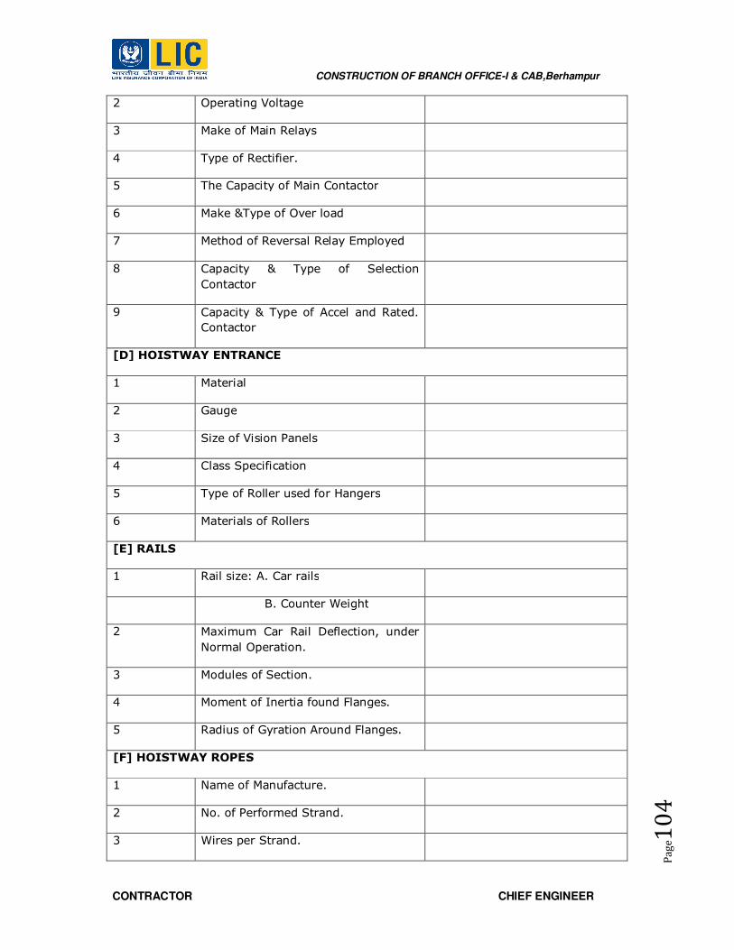
CONSTRUCTION OF BRANCH OFFICE-I & CAB,Berhampur
CONTRACTOR CHIEF ENGINEER
Pa
ge1
04
2 Operating Voltage
3 Make of Main Relays
4 Type of Rectifier.
5 The Capacity of Main Contactor
6 Make &Type of Over load
7 Method of Reversal Relay Employed
8 Capacity & Type of Selection
Contactor
9 Capacity & Type of Accel and Rated.
Contactor
[D] HOISTWAY ENTRANCE
1 Material
2 Gauge
3 Size of Vision Panels
4 Class Specification
5 Type of Roller used for Hangers
6 Materials of Rollers
[E] RAILS
1 Rail size: A. Car rails
B. Counter Weight
2 Maximum Car Rail Deflection, under
Normal Operation.
3 Modules of Section.
4 Moment of Inertia found Flanges.
5 Radius of Gyration Around Flanges.
[F] HOISTWAY ROPES
1 Name of Manufacture.
2 No. of Performed Strand.
3 Wires per Strand.

CONSTRUCTION OF BRANCH OFFICE-I & CAB,Berhampur
CONTRACTOR CHIEF ENGINEER
Pa
ge1
05
4 Lay
5 Tensile Strength of Rope
6 Safety Factor of Rope
[G] BUFFERS
1 Type of Car Buffers
2 No. of Car Buffers
3 Type of Counter Weight Buffers
4 No. of Counter Weight Buffers
5 Stroke of Car Buffers
6 Stroke of Counter Weight Buffers.
7 Average Retardation Speed Buffer at
Rated Load
8 Peak Retardation for all Buffers at
Rated Load
9 Duration of Peak Retardation at Rated
Load
[H] GEAR BOX
1 Type
2 Input Speed
3 Out Put Speed
4 Gear Ratio: 40 :
5 Cyclic Duration Factor
6 Capacity (i) Input H.P.
7 Capacity (ii) Out Put Torque
8 Type of Bearings
9 Un – Balance Torque (Lp – in)
[I] BRAKE
1 Type
2 Duty

CONSTRUCTION OF BRANCH OFFICE-I & CAB,Berhampur
CONTRACTOR CHIEF ENGINEER
Pa
ge1
06
3 Size
4 Brake Shoe
5 Lining
6 Torque T
7 Type of winding
8 Shape & Size of Shaft
9 Operating Mechanism
[J] SAFETIES
1 Furnish the List of Safeties Included.
2 The Equipment Offered Must Confirm
to ISI Bombay

CONSTRUCTION OF BRANCH OFFICE-I & CAB,Berhampur
CONTRACTOR CHIEF ENGINEER
Pa
ge1
07
19.0 EXTRA LOW VOLTAGE WORKS SPECIFICATIONS
ELV SYSTEM
SECTION-1 : TELEPHONE POINT WIRING
1.0 Scope :
1.1 The scope of work shall cover supply, installation, commissioning and testing of :
i) Telephone cables/wires
ii) Telephone Tag Blocks
iii) Telephone wiring in conduits
iv) Telephone Outlet points
2.0 Telephone cables
All multi core cables / wires shall be of tinned copper conductor of not less than 0.5
sqmm and shall be colour coded twisted pairs with rip cord.
The conductor resistance shall be less than 150 ohms per KM and the insulation
resistance between the conductors not less than 50 mega ohms and the nominal
capacitance of about 0.1 micro farad per kilometer.
Cables laid underground or locations subject to dampness and flooding shall be filled
with polyethylene compound and shall have sufficient protection against moisture and
water ingress.
All armoring shall be of galvanized steel wires and protected against corrosion by an
outer sheath of PVC in the case of indoor cables and polyethylene in the case of outdoor
cables. Outer sheathing must be fire retarding and anti-termite.
All unarmoured single core cables and inner sheath of armored cables shall be provided
with rip cord.

CONSTRUCTION OF BRANCH OFFICE-I & CAB,Berhampur
CONTRACTOR CHIEF ENGINEER
Pa
ge1
08
All single pair cables for final extension to the telephone outlet box shall be unarmoured
tinned copper conductors of not less than 0.5 mm. diameter and shall be drawn in
conduits. All telephone outlets shall consist of 2 A 2 pair polythene connector in G.I box
with 6 mm per spex cover with beveled edges and chromium plated brass hardware.
3.0 Tag blocks :
3.1 The telephone tag blocks shall be suitable for the multi core telephone cables and
shall have two terminal blocks, cross connect type. All incoming and outgoing cables
shall be terminated on separate terminal blocks and termination shall be silver soldered.
The cross connecting jumpers shall be insulated wires of same diameter and screw
connected.
3.2 The tag blocks shall be mounted inside fabricated sheet steel boxes with removable
hinged covers and shall be fully accessible. The enclosure shall be painted with 2 coats of
red oxide and stove enameled.
Section 2: Data/Structured Cabling:
A Local Area Network is to be set-up using structured cabling with required connections
at branch office.
GENERAL NETWORKING PARAMETERS
The general networking parameters should conform to the standard parameters for the
structured cabling which provides a single network infrastructure with a high degree of
future expansion inherent in the design. The cabling system should be able to support
full range of IT requirements including Voice, Data, and Video & Security systems. The
floor cabling to be of Cat-6A cable to ensure data frequencies should be up to 500 MHz.
The main Back Bone cabling and the network components should cater for supporting
the full range of IT requirements of the branch office.
CABLING PHILOSOPHY
The cabling should cater for the whole Network in the respective floor and offer the
following :
a. Ability to move from system to system without changing the cable network.
b. Flexibility for moves and changes.
c. A versatile cable system capable of handling video, audio, security & control in
addition to data and voice.
d. Reduced network management overhead.
e. Enhanced vendor independent hardware choice.
f. Independently isolating certain areas from the Network, when required, due to
faults.
CABLING LAYOUT

CONSTRUCTION OF BRANCH OFFICE-I & CAB,Berhampur
CONTRACTOR CHIEF ENGINEER
Pa
ge1
09
A structured cabling system must be built according to ANSI / TIA / EIA-568-A
/ 568-B standards. Accordingly there shall be six functional sub systems as
follows.
Entrance Facility :
The entrance facility introduces cables and associated hardware into the building.
It is the demarcation point between carrier and the organisation. The over-
voltage protection devices are located here. Entrance facilities could be used for
public network services, private network services or both.
Telecommunication closet
The telecommunications closet is where the horizontal distribution cables are
terminated. All recognized types or horizontal cabling are terminated on
compatible connecting hardware. Similarly, recognized backbone cables are also
terminated in the closet. Cross-connection is done with jumpers or patch cords to
provide flexible connectivity for extending various services to users at the
telecommunications outlets.
Horizontal Cabling
Horizontal Cabling consists of the physical media used to connect each outlet to a
closet.
Work area
Work area components extend the telecommunications outlet / connector end of
the horizontal cabling system to the station equipment. All adapters, filters or
converters that are used to adapt the electronic equipment to the structured
cabling system must be external to the telecommunications outlet.
Topology
Wherever new cabling for a premises is envisaged the proposed structured
cabling system shall use star topology. Each work area telecommunications outlet
must be connected to a cross-connect in a telecommunications closet. All cables
from an area in the respective floor, therefore, run back to one central point for
administration. Each telecommunications closets must be star-wired back to the
equipment room for the building. In a campus environment, where the cabling
extends to two or more buildings, each building is star-wired back to one main
administration area.
Unshielded Twisted Pair ( UTP ) Cables
Cat 6A Product Specifications:
The CAT- 6A cable is envisaged to be used for Data in the horizontal cabling ( i.e
between Rack to respective Information Outlets ). The cable shall meet /
supported by the ANSI / TIA / EIA-568-A (568-B ) standard.
Installation
a. Proper installation practices are vital for high performance. Installation tasks such
as pulling cables or untwisting cables may degrade overall system performance.

CONSTRUCTION OF BRANCH OFFICE-I & CAB,Berhampur
CONTRACTOR CHIEF ENGINEER
Pa
ge1
10
Extreme tension on the cable could stretch the twists, or untwist the pairs or
increase attenuation. The 568-A / 568-B standard specifies that the pairs in a
CAT-6A cable should never be twisted more than half-inch from the point of
termination. Additional twisting will increase crosstalk and reduce protection
from EMI/RFI. The use of proper pull techniques, pull cords and cable lubricants
will prevent this type of damage.
b. The cable is bent as it passes through walls, ceilings, floors, ducts and corners. It
is crucial not to exceed the minimum bend radius of the cable being installed.
c. Terminating the cables involves stripping away some of the protective insulating
material and untwisting the conductors. Do not remove more insulation material
than necessary.
d. After terminating the cables, they have to be 'dressed’ or managed. This involves
arranging the cables in such a way so as to provide strain relief. Thin plastic
strips shall be used to bundle the cables.
e. The labeling and marking will be done on each terminal box and cable to identify
the pairs. The labeling & marking shall be done in consultation with LIC
f. The cables / wires will be run in Raceways / PVC / MS conduits.
g. Special care will be taken to isolate wires/ cables from electrical wires and a
minimum separation will be maintained to prevent induction / interferences.
h. The wiring on the terminal boxes and the colour code scheme of the cable pairs
will be in accordance with the standard practice used for such installations.
Structured Cabling System
1. The cabling and associated work shall be carried out in accordance with the
industry standards.
2. The cabling solution should be flexible and capable of including new facilities or
technologies, as they become required or available.
3. The Cabling solution should cover its capacity and functionality with minimum
components.
4. The contratcor shall label all cables and cords, distribution frames and outlet
locations, according to industry standards.
5. The solution should support analog and digital applications, data, Local Area Net
Works and video on a common cabling platform.
6. The cabling system proposed by the vendor shall meet the specifications as
prescribed in ANSI/EIA/TIA, ISO 11801 and EN 50173 standards.
7. All the conduits /casing capping used during installation used by Contractor
should have the ISI mark certification.
8. All the cabling components should preferably be from single manufacturer.
EQUIPMENT / DATA RACK
The rack shall be of one of the approved makes as listed in the list of approved makes.
The rack shall be made out of mild steel of not less than 1.6mm thick and powder
quoted after due procedures as required. The rack shall be of specified size with suitable
cable managers in the sides. The rack shall be provided with coasters for facilitating easy
movement and shall have screw type adjustable base.
CONSTRUCTION OF BRANCH OFFICE-I & CAB,Berhampur
CONTRACTOR CHIEF ENGINEER
Pa
ge1
11
At the Top and bottom of the rack there shall be removable gland plate with requisite
knockouts for entry of cables & conduits. The front door shall be of glass contained in an
MS frame. The side doors shall be provided with suitable slots at the bottom half portion
to facilitate the entry of air. All the doors shall be lockable preferably with a single key.
Further all the doors shall be removable, after opening the locks, to facilitate easy
working during maintenance. The racks shall be provided with four fans at the top for
forced cooling of the components. (Approx. capacity of each fan shall be 90 CFM).
The profile of the rack shall be got approved before placing the order. Power strip of
appropriate suitable Nos. of 5A / 6A 3 Pin universal or 5 pin sockets and 15A sockets, 1
No. Fuse with base & grip and 1 No. neon indicator shall be provided on one of the sides
of the rack at the rear portion.
CAT 6A Specifications
1. Cat 6A UTP cables :
• 4 pairs, Unshielded twisted pair solid cable, 23 AWG Cat 6A ratings.
• Meets and exceeds EIA/TIA 568-B.2-1 Cat 6A specifications
• Centralized separator to reduce the noise level
• Performance tested at 600 MHz frequency
• Supports Giga applications
2. Cat 6A Information Outlet:
a. Face Plate
• High Impact Plastic Body ABS FR Grade
• Spring Shuttered Front Access
• Flush or Surface mountable with a back mount frame.
b. Keystone Jack Module with bezel
• Performance exceeds EIA/TIA 568-B.2-1 Cat 6 specifications
• Flame retardant Plastic body UL-94V-0 rated
• Spring contact : 50 micron over 100 micron nickel
• Current rating : 1.7 Amps
• Contact resistance : 15 Ohms max
• Insulation resistance:500M-Ohms min
3. Cat 6A Patch Cords:
a. Patch cable
• Multi-strand and highly Flexible 4 pair 100 Ohms patch cables
• Should meet and exceed TIA/EIA 568-B.2-1 cat 6 specifications
• Pairs separated by PE former to control the noise.
• HDPE insulation over the conductors
• In different colors ( floorwise ) .

CONSTRUCTION OF BRANCH OFFICE-I & CAB,Berhampur
CONTRACTOR CHIEF ENGINEER
Pa
ge1
12
b. RJ 45 connector
• Three piece, two layered design
• Gold contacts, 50 micron gold over nickel; polycarbonate housing UL94V
• Voltage : 30V Current: 1.5A
• Contact Resistance : 20 M –Ohms
• Connection : 8P8C
• Wiring : 24- 26 AWG
4. Plate
a. Face Plate
• High Impact Plastic Body ABS FR Grade
• Spring Shuttered Front Access
• Flush or Surface mountable with a back mount frame.
b. Keystone Jack Module with bezel
• Performance meets or exceeds EIA/TIA 568-B.2-1 Cat 5e specifications
• Flame retardant Plastic body UL-94V-0 rated
• Spring contact : 50 micron over 100 micron nickel
• Current rating : 1.7 Amps
• Contact resistance : 15 Ohms max
• Insulation resistance:500M-Ohms min
All features supported must be IEEE standard based features to avoid any
interoperability issue with other vendor switch.
SECTION-3: CONVENTIONAL FIRE DETECTION & ALARM SYSTEM
Fire detection & alarm systems shall be designed for conventional fire alarm panel,
,Optical smoke detectors, Heat detectors, Manual call points, Input & Output modules.
Electronic hooters, Response indicators, Strobe, Floor indicator panels and Repeater fire
alarm panels.
1. Manual Call Points (MCPs)
It shall be of ‘break glass’ type, and 1.5mm thick welded sheet steel or 3 mm thick cast
aluminium. The front glass shall be breakable. The MCPs shall be recess mounted
suitable to support the fire panel. It shall form an integral part of the fire detector
system. The housing shall be dust/vermin proof properly sealed with rubber lining. The
glass frangible element shall keep a push button pressed inside such that in the event of
breaking the glass, the push button is released to actuate an alarm in the control panel.
CONSTRUCTION OF BRANCH OFFICE-I & CAB,Berhampur
CONTRACTOR CHIEF ENGINEER
Pa
ge1
13
Where sheet steel is used for, this shall be thoroughly cleaned off dust, dirt, grease and
rust if any and two coats of anti rust primer shall be given both inside and outside. This
shall be followed by two coats of synthetic enamel paint in fire red colour on the external
surface that will be visible on installation. In the case of cast aluminium body for a call
box, the surface shall be neatly finished with red colour paint. The following words shall
be painted on the front of the call box in contrasting colour with a letter size of not less
than 5mm.
“BREAK GLASS IN CASE OF FIRE”
Installation requirements:-
Manual call points shall be located at exit space and shall be installed at a height of 1.4
m above the floor at an easily accessible position. They shall be installed at easily
accessible, well illuminated positions, preferably in a contrasting background so that they
are easily noticeable from either direction. They may be semi-recessed so as to project
by 10mm. They shall be installed free from obstructions.
2. Hooters
The loop hooters shall be so arranged that when any alarm operates all the hooters
throughout the premises shall be activated. The hooters at the fire alarm shall be
electronic type having frequency of suitable frequency range. The hooters shall be
capable to produce a sound output of 90 db at 1 m. Hooters shall be of loop powered
and no separate power is required.
Fire alarm hooters shall not be used for any purpose other than for fire operations. When
installed flush with a false ceiling these shall match the ceiling surface. Necessary
provisions such as metal/ wooden boxing or frame work, if required, to accommodate
the hooters shall be provided in the ceiling. It shall be installed at a height not lower
than 2.4 m, except when recessed in a false ceiling of lower height, in such cases the
hooters shall be recessed at false ceiling level.
The panel hooters in the respective panels shall be actuated automatically as soon as fire
alarm signal is initiated from any trigger device connected to them. These shall also be
sounded when there is a fault alarm signal within their areas of control. The sound shall
be continuous and of the same characteristics from all fire alarm hooters in a building.
The isolator module shall mount in a standard suitable size electrical box or in a surface
mounted back box. It shall provide a single LED that shall flash to indicate that the
isolator is operational and shall illuminate steadily to indicate that a short circuit
condition has been detected and isolated.
3. Fire Alarm Control Panel
CONSTRUCTION OF BRANCH OFFICE-I & CAB,Berhampur
CONTRACTOR CHIEF ENGINEER
Pa
ge1
14
The fire alarm control panel shall be designed to give reliable and continuous operation
for long time with several advantages features. The panel shall be conventional type
suitable for 2 wire loops system. Being modular in design, it shall be very easy for
maintenance and testing
of the system. Fire Alarm panel consists of following plug in type modules
i. Power module.
ii. Charger module.
iii. Control module.
iv. Loop modules.
The fire alarm control panel shall be housed in a steel enclosure. It shall also be finished
with hard wear textured epoxy paint/ powder coated. Cable entries shall be provided on
the top and bottom of the panel.
The system capacity shall be based on the number of devices and control modules.
Eachdevices in the system shall be identified by its unique address position on the two
wire loop.
The panel retains command over the alarm process, LED indicators, automatic test
feature and loop hooters.
a. Basic system Functional Operations
When a fire alarm/trouble condition is detected and reported by one of the system
initiating
devices or appliances, the following functions shall immediately occur:
� The system Alarm LED shall flash or the system trouble LED shall flash.
� A local piezo-electric signal in the control panel shall sound.
� The LCD display shall indicate all information associated with the fire
alarm/trouble condition, including the type of alarm point and its location within
the protected premises.
b. Enclosures
The control panels shall be housed in cabinets suitable for surface or semi-flush
mounting.
Cabinets shall be corrosion protected, given a rust-resistant prime coat, and
manufacturer's standard finish.
The back box and door shall be constructed of min. 16 gauge sheet steel with provisions
for electrical conduit connections into the sides and top. The door shall provide a key
lock and include a transparent opening for viewing all indicators. For convenience, the
door shall have the ability to be hinged on either the right or left-hand side.
The control unit shall be modular in structure for ease of installation, maintenance, and
future expansion.
c. Power supply
CONSTRUCTION OF BRANCH OFFICE-I & CAB,Berhampur
CONTRACTOR CHIEF ENGINEER
Pa
ge1
15
The power supply units shall operate on 240 Volts AC, 50Hz, and shall provide all
necessary power for the smooth operation of system. In case of failure of main power
supply the power supply unit shall draw power from a set of standby batteries. The
capacity of the battery set shall be sufficient to meet the required hours full functioning
of the complete system under alarm conditions. It shall provide a battery charger using
dual-rate-charging techniques for fast battery recharge. It shall charge completely
discharged batteries within a 12-hour period. It should provide meters to indicate
battery voltage and charging current.
d. Batteries and External Charger
Battery
Battery shall have sufficient capacity to power the fire alarm system for not less than
two hours in alarm condition and at least 8 hours in normal condition. The batteries are
to be completely maintenance free.
External Battery Charger
Shall be completely automatic, with constant potential charger maintaining the battery
fully charged under all service conditions. Charger shall operate from a 230 volt 50 hertz
source. It shall be rated for fully charging a completely discharged battery within 12
hours while simultaneously supplying any loads connected to the battery. It shall have
protection to prevent discharge through the charger. It shall also have protection for
overloads and short circuits on both AC and DC sides.
4. Control Cable
The control cable for wiring fire alarm system shall be 2 x 1.5 sq.mm ZHFR unarmored
Copper cable including PVC MMS FRLS rigid conduits conducting.
5. Conventional Detectors
All types of detectors shall be of manually programmable type using dip-switches or
handheld programmer or from fire control panel. The detector shall have no moving
parts of components subject to wear. It shall be possible to test the detector in the field.
The response of a detector shall always be clearly visible from outside by a flashing light
on the base. The detector shall connect to the control unit via a fully supervised two-wire
circuit. A built barrier shall prevent entry of insects into the sensor. The detector shall be
designed for fast and simple cleaning. All electronic circuits must be solid state devices
and virtually hermetically sealed to prevent their operation from being impaired by dust
dirt or humidity. All circuitry must be protected against usual electrical transients and
electromagnetic interference. All radioactive parts of the source, if any, shall be fully
gold plated. The detector shall be inserted into or removed from the base by a simple
push-twist mechanism to facilitate easy exchange for cleaning and maintenance.
The smoke & heat detectors shall fit into a common type standard base. The standard
base shall be supplied with a seal plate, preventing dirt, dust, condensation or water
reaching the wire terminals or the detector points. Detectors shall be provided with a MS
box for entry and termination of armoured cable and to protect detectors terminals.
CONSTRUCTION OF BRANCH OFFICE-I & CAB,Berhampur
CONTRACTOR CHIEF ENGINEER
Pa
ge1
16
At the time of installation and prior to commissioning, every detector shall be allotted an
identification number. Detectors shall not be either partially or totally recessed in ceiling
or wall. Detectors shall be suitably protected where they are liable to be subjected to
mechanical damage. Detectors shall not be painted or coated or covered in any manner
after installation as this will adversely affect the sensitive of operation.
Smoke detectors
It shall be of optical type. Smoke detectors shall quickly respond to smoke containing
small particles normally produced and automatically adjusts sensitivity without needing
operator intervention.
24.0 TECHNICAL SPECIFICATIONS FOR SIGNAGE
BOQ SPECIFIED:
ACP Background Board
Scope of work:
This work includes supply, installation, testing and commissioning ACP Background board
on building top of specified size, to be installed in the same on the locations as specified
in detailed drawings and as per Architect/ Engineer-in-Charge.
Material & Workmanship:
ACP Background board shall be of required thickness, smooth matt finish, illuminated
with yellow and blue led and face glow letters above it. The frame shall be offset from
the glazing and shall be supported by the floor beams on Terrace and Terrace Floor. The
peripheral gap space between front side and the backing shall also be covered with
acrylic sheets, having a width of 500 to 700 mm. Aluminium framework and inclusive of
two coats of primer and anti-corrosive paint. Complete for all height, levels, floors in all
shapes as per the Architectural drawings and directions of engineer-in-charge. The Work
shall be carried out as per manufacturer's instructions, detailed drawings and
Architect/EIC instructions.
Mode of Measurement & Payment:
The rate shall include all materials, tools, plants and labour involved in satisfactory
completion of work as prescribed above. Rate to include cost of steel framework,
Aluminium framework and inclusive of two coats of primer and anti-corrosive paint. The
Measurement of the item shall be per Sqm. basis.
Box Type Metal Letter
Scope of work:

CONSTRUCTION OF BRANCH OFFICE-I & CAB,Berhampur
CONTRACTOR CHIEF ENGINEER
Pa
ge1
17
This work includes supply, installation, testing and commissioning Box type metal letter
on Entrance of the building of specified size, to be installed in the same on the locations
as specified in detailed drawings and as per Architect/ Engineer-in-Charge.
Material & Workmanship:
Box type metal letters forming composite box made from 1mm thick stainless steel plate
of grade 304 shall be of colour finish of approved colour by consultant /client. The frame
shall be offset from the glazing and shall be supported by the floor beams on Terrace
and Terrace Floor. The peripheral gap space between front side and the backing shall
also be covered with acrylic sheets, having a width of 500 to 700 mm. Aluminium
framework and inclusive of two coats of primer and anti-corrosive paint. Complete for all
height, levels, floors in all shapes as per the Architectural drawings and directions of
engineer-in-charge. The Work shall be carried out as per manufacturer's instructions,
detailed drawings and Architect/EIC instructions.
Mode of Measurement & Payment:
The rate shall include all materials, tools, plants and labour involved in satisfactory
completion of work as prescribed above. Rate to include cost of steel framework,
Aluminium framework and inclusive of two coats of primer and anti-corrosive paint. The
Measurement of the item shall be per Sqm. basis.
Back Painted Toughen Glass of 8mm thickness, chrome finished in Signage
Board
Scope of work:
This work includes supply, installation, testing and commissioning Back Painted toughen
glass of 8mm thickness, chrome finished in Signage Board on Entrance of the building of
specified size, to be installed in the same on the locations as specified in detailed
drawings and as per Architect/ Engineer-in-Charge.
Material & Workmanship:
Back Painted toughen glass of 8mm thickness, chrome finished in Signage Board.
Glazing clips, S.S Struds of approved shade etc. Size & Height of glass shall be 600 mm
X 450 mm & 50 mm respectively. Complete for all height, levels, floors in all shapes as
per the Architectural drawings and directions of engineer-in-charge. The Work shall be
carried out as per manufacturer's instructions, detailed drawings and Architect/EIC
instructions.
Mode of Measurement & Payment:
The rate shall include all materials, tools, plants and labour involved in satisfactory
completion of work as prescribed above. The Measurement of the item shall be per Sqm.
basis.
Lift Signage- Stainless Steel Plate
Scope of work:

CONSTRUCTION OF BRANCH OFFICE-I & CAB,Berhampur
CONTRACTOR CHIEF ENGINEER
Pa
ge1
18
This work includes supply, installation, testing and commissioning Stainless steel plate
for Lift Signage of the building of specified size, to be installed in the same on the
locations as specified in detailed drawings and as per Architect/ Engineer-in-Charge.
Material & Workmanship:
Stainless steel plate of grade 304 having 2.5 mm thick (brush finish) shall be used with
back side LED light of approved colour by Architect/EIC. Size of plate shall be 600 mm X
450 mm. The size of Laser cut fonts arrows or logo shall be as per drawing. Complete for
all height, levels, floors in all shapes as per the Architectural drawings and directions of
engineer-in-charge. The Work shall be carried out as per manufacturer's instructions,
detailed drawings and Architect/EIC instructions.
Mode of Measurement & Payment:
The rate shall include all materials, tools, plants and labour involved in satisfactory
completion of work as prescribed above. The Measurement of the item shall be per Sqm.
basis.
Toilet Signage- Stainless Steel Plate
Scope of work:
This work includes supply, installation, testing and commissioning Stainless steel plate
for Toilet Signage of the building of specified size, to be installed in the same on the
locations as specified in detailed drawings and as per Architect/ Engineer-in-Charge.
Material & Workmanship:
Stainless steel plate of grade 304 having 2.5 mm thick (brush finish) shall be used. Size
of plate shall be 250 mm X 60 mm. The height of the laser cut fonts arrows or logo shall
be as per Drawing. Complete for all height, levels, floors in all shapes as per the
Architectural drawings and directions of engineer-in-charge. The Work shall be carried
out as per manufacturer's instructions, detailed drawings and Architect/EIC instructions.
Mode of Measurement & Payment:
The rate shall include all materials, tools, plants and labour involved in satisfactory
completion of work as prescribed above. The Measurement of the item shall be per Sqm.
basis.
Toilet Signage- Stainless Steel Plate
Scope of work:
This work includes supply, installation, testing and commissioning Stainless steel plate
for Toilet Signage of the building of specified size, to be installed in the same on the
locations as specified in detailed drawings and as per Architect/ Engineer-in-Charge.
Material & Workmanship:
Stainless steel plate of grade 304 having 2.5 mm thick (brush finish) shall be used. Size
of plate shall be 180 mm X 180 mm. The height of the laser cut fonts arrows or logo

CONSTRUCTION OF BRANCH OFFICE-I & CAB,Berhampur
CONTRACTOR CHIEF ENGINEER
Pa
ge1
19
shall be as per Drawing. Complete for all height, levels, floors in all shapes as per the
Architectural drawings and directions of engineer-in-charge. The Work shall be carried
out as per manufacturer's instructions, detailed drawings and Architect/EIC instructions.
Mode of Measurement & Payment:
The rate shall include all materials, tools, plants and labour involved in satisfactory
completion of work as prescribed above. The Measurement of the item shall be per Sqm.
basis.
All Rooms Signage- Stainless Steel Plate
Scope of work:
This work includes supply, installation, testing and commissioning Stainless steel plate
for all Rooms & Water tank Signage of the building of specified size, to be installed in the
same on the locations as specified in detailed drawings and as per Architect/ Engineer-
in-Charge.
Material & Workmanship:
Stainless steel plate of grade 304 having 2.5 mm thick (brush finish) shall be used. Size
of plate shall be as per detailed drawings and Architect/EIC instructions. The height of
the laser cut fonts arrows or logo shall be as per Drawing. Complete for all height, levels,
floors in all shapes as per the Architectural drawings and directions of engineer-in-
charge. The Work shall be carried out as per manufacturer's instructions, detailed
drawings and Architect/EIC instructions.
Mode of Measurement & Payment:
The rate shall include all materials, tools, plants and labour involved in satisfactory
completion of work as prescribed above. The Measurement of the item shall be per Sqm.
basis.
FIRE FIGHTING SYSTEM
MATERIAL TESTING
The project incharge engineer shall have full power to get any material of work to be tested by an
independent agency at contractor’s expense in order to prove the soundness and adequacy.
TESTING OF THE SYSTEM
• After laying and jointing, the entire piping shall be tested to hydrostatic test pressure.
• The pipes shall be slowly charged with water so that the air is expelled from the pies.
• The pipes shall be allowed to stand full of water for a period of not less than 24 hours and then
tested under pressure.
• The test pressure shall be 12 kg/cm2. The test pressure shall be applied by means of manually
operated test pump or by a power driven test pump to be provided by the contractor.
CONSTRUCTION OF BRANCH OFFICE-I & CAB,Berhampur
CONTRACTOR CHIEF ENGINEER
Pa
ge1
20
• In either case precautions shall be taken to ensure that the required test pressure is not exceeded.
• The open end of the piping shall be temporarily closed for testing.
• Test shall be conducted on each pump set after completion of the installation with respect of
delivery head, flow and B.H.P.
• The test shall be carried out by the contractor at his own cost.
• All leaks and defects in different joints, noticed during the testing and before commissioning shall
satisfaction of engineer.
• Testing of fittings/ equipments shall be carried out either at site or at works in the presence of a
representative of the engineer.
• Test certificates shall also be furnished by the contractor.
• The automatic operation of the system for the various functional requirements and alarms as laid
down in his specification shall be satisfactory carried out on pressure of the engineer.
Fire Fighting Equipment
SP:7 Amendment No. III to NBC Part-IV Fire Protection Jan
1997
TAC Tariff Advisory Committee fire protection manual Part-I.
TAC Rules of Tariff Advisory Committee for automatic sprinkler
system.
NFPA : 12 , 1993 Standards on Carbon Dioxide Extinguishing System
IS : 636 Non-percolating flexible fire fighting delivery hose.
IS : 884 Specification for first aid hose reel for fire fighting.
IS : 901 Specification for couplings, double male and double female,
instantaneous pattern for fire fighting.
IS : 902 Suction hose couplings for fire fighting purposes.
IS : 903 Specification for fire hose delivery couplings, branch pipe,
nozzles and nozzle spanner.
IS : 904 Specification for 2-way and 3-way suction collecting heads
for fire fighting purposes.
IS : 907 Specification for suction strainers, cylindrical type for fire
fighting purposes.
IS : 908 Specification for fire hydrant, stand post type.
IS : 909 Specification for underground fire hydrant, sluice valve type.
IS : 910 Specification for portable chemical foam fire extinguisher.

CONSTRUCTION OF BRANCH OFFICE-I & CAB,Berhampur
CONTRACTOR CHIEF ENGINEER
Pa
ge1
21
IS : 933 Specification for portable chemical foam fire extinguisher.
IS : 1648 Code of practice for fire safety of building (general) : Fire
fighting equipment and its maintenance
IS : 2171 Specification for portable fire extinguishers dry powder
(cartridge type)
IS : 2190 Selection, installation and maintenance of first aid fire
extinguishers – Code of practice.
IS : 2871 Specification for branch pipe, universal, for fire fighting
purposes.
IS : 2878 Specification for fire extinguishers, carbon dioxide type
(portable and trolley mounted).
IS : 3844 Code of practice for installation and maintenance of internal
fire hydrants and hose reel on premises.
IS : 5290 Specification for landing valves.
IS 5714 Specification for coupling, branch pipe, nozzle, used in hose
reel tubing for fire fighting.
IS : 8423 Specification for controlled percolation type hose for fire
fighting.
IS : 10658 Specification for higher capacity dry powder fire
extinguisher (trolley mounted).
IS : 11460 Code of practice for fire safety of libraries and archives
buildings.
IS : 1309 External hydrant systems – Provision and maintenance –
Code of practice.
IS : 5514 (Parts 1 to 7) Reciprocating internal combustion engines : Performance
IS : 3589 Seamless or electrically welded steel pipes for water, gas
and sewage (168.3 mm to 2032 mm outside diameter).
IS : 3989 Centrifugally cast (sun) iron spigot and socket soil, waste
and ventilating pipes, fittings and accessories.
IS : 4346 Specifications for washers for use with fittings for water
services.
IS : 4711 Methods for sampling steel pipes, tubes and fittings.
IS : 6392 Steel pipe flanges
CONSTRUCTION OF BRANCH OFFICE-I & CAB,Berhampur
CONTRACTOR CHIEF ENGINEER
Pa
ge1
22
IS : 6418 Cast iron and malleable cast iron flanges for general
engineering purposes.
IS : 7181 Specification for horizontally cast iron double flanged pipe
for water, gas and sewage.
IS : 10221 Code of practice for coating and wrapping of underground
mild steel pipelines.
IS : 11149 Rubber Gaskets
MEDIUM/ HV VOLTAGE PANELS
TESTING
The power control centers shall be tested at factory after assembling of all components and
completion of all interconnections and wiring. Tests shall be conducted in accordance with the
requirements of BS:3659.
Insulation Test
Insulation of the main circuit, i.e. the insulation resistance of each pole to the earth and that
between the poles shall be measured.
Insulation resistance to earth of all secondary wiring should be tested with 1000 Volt magger.
Insulation test shall be carried out both before and after high Voltage test. High Voltage Test A
High Voltage test with 2.5 KV for one minute shall be applied between the poles and earth. Test
shall be carried out on each pole in turn with the remaining poles earthed, all units raked in
position and the breakers closed. Original test certificate shall be submitted along with panel.
TESTING
The power control centers shall be tested at factory after assembling of all components and
completion of all interconnections and wiring. Tests shall be conducted in accordance with the
requirements of BS:3659.
SHORT CIRCUIT AND TYPE TEST:
Bus way system shall comply with following standards:
IEC 61439-1&6
All type test certificates according to above standards shall be of International Lab of repute such
as CPRI or equivalent.

CONSTRUCTION OF BRANCH OFFICE-I & CAB,Berhampur
CONTRACTOR CHIEF ENGINEER
Pa
ge1
23
Type test certificate shall be produced for validation before ordering for Rated Short Circuit
breaking capacity for 1sec.
Type Test certificates confirming Mechanical Operation and Temp. Rise of Tap Off Box of similar
design in accordance with IEC-61439 are must.
BUS DUCTS & BUS BAR CAHMBERS
Busway manufacturer shall produce a Type Test Report determining Rating of Busway at
Ambient Temp. with no deration. Failure to submit such reports will disqualify the manufacturer.
A Type Test report confirming Degree of Protection in accordance with IEC 60529 is must.
The type test for IEC-60068 of seismic certificate of green premium product from independent
test house is a must.
Type test reports.
Switchboard configurations offered shall be CPRI /Independent international test house tested
for all the tests as per IEC61439-1 & 2 and internal arc tests as per IEC61641. Copies of the test
certificates shall be submitted with the tender.
Testing At Works
Copies of type test carried out at ACB/ MCCB manufacturers works and routine tests carried out
at the switchboard fabricators shop shall be furnished along with the delivery of the
switchboards. Engineer-in-Charge reserves the right to get the switchboard inspected by their
representative at fabricators works prior to dispatch to site to witness the followings.
Physical variation and dimensional check
Functional check
HV test
IR test
TESTS
Unless otherwise specified, the specifications for testing shall be as follows.
SWITCH GEARS
TESTS & INSPECTIONS
Switchgear shall be subjected to routine tests as per IS 8623. Vendor has to arrange for the Test Reports.
All meters and other reference devices used for testing shall be valid calibration from reputed national
laboratories / Institutes. Inspection by purchasers shall not be carried out unless the vendor confirms that
equipment is ready for proceeding with the tests.
Shop test shall be witnessed by Engineer-In- Charge or his authorized representative. Prior notice of
minimum 4 weeks shall be given to the inspector for witnessing the tests.
Acceptance tests on completed switchboards shall be as follows:

CONSTRUCTION OF BRANCH OFFICE-I & CAB,Berhampur
CONTRACTOR CHIEF ENGINEER
Pa
ge1
24
a) A general visual check shall be carried out. This shall cover measurement of over all
dimension, location, number and type of devices, terminal boxes, location and connection of
terminals etc.
b) Checking of bill of materials as per approved drawing.
c) Checking of operation of various feeders as per approved schematic drawings.
d) Operation check shall be carried out for every control function as per schematic drawings by
manually simulating fault conditions and operation of control switches/relays etc.
e) Checking of inter-changeability of identical feeders.
f) Insulation resistance test and value measurement on power and control circuits before and
after high voltage withstand test.
g) High voltage test on power and control circuit as per IS 8623.
h) For equipment bought from other suppliers, certified test reports of tests carried out at the
manufacturers works shall be submitted. Normally all routine tests as specified in the
relevant standards shall be conducted by the sub supplier at its works and copies of routine
test reports shall be furnished.
TYPE TEST
The type test certificates shall be submitted to inspecting officer
The agency shall be CPRI test certificate for similar panel (LT Panels or MCC). Panels shall be
got manufactured by only reputed panel manufacturers having got type tested by CPRI or other
Government testing laboratory on similar panels (LT panel or MCC) of minimum 50KA fault level
with stand capacity and IP protection.
ROUTINE/ACCEPTANCE TESTS
The panels shall be checked and tested after fabrication, assembling and wiring at factory as per
the following.
Tests
1 Insulation resistance test. Wiring test shall be carried with 1000-volt Megger to ensure
adequate insulation resistance. (At manufacturer’s works). While carrying out the IR test the
capacitor banks shall be isolated.
2 H.T. test shall be carried out as per IS at manufacturer’s works.
3 Functional tests.
4 Primary/secondary current injection test for relays if protection relays are supplied as part of
BOQ
SITE TESTS
In addition to the tests at manufacturer’s premises, all relevant pre-commissioning checks and
tests shall be done at site before energizing the panel.
Following shall be the minimum checks/tests to be done at site.
1. Physical inspection for breakages/damages/orderliness.

CONSTRUCTION OF BRANCH OFFICE-I & CAB,Berhampur
CONTRACTOR CHIEF ENGINEER
Pa
ge1
25
2. Insulation resistance test with 500 V Megger by isolating the Capacitor bank. The
insulation resistance shall be not less than 100 mega ohms.
3. Earth continuity test.
4. Tightness of joints/connections/terminations.
5. Safety checks.
6. General Operation/Performance Checks
HT CABLES
TESTS AND TESTING FACILITIES:
TYPE TESTS:
All the type tests in accordance with IS: 7098 (Part 2) - 1985, amended up to date, shall be
performed on cable samples drawn by purchaser. Type tests are required to be carried out from
the first lot of supply on a sample of all sizes of cables ordered for each voltage grade. In case
facilities of any of the type tests are not available at the works of the supplier, then such type test
shall be carried out by the supplier at the independent laboratory at the cost of supplier. Sample
for the type test will be drawn by the purchaser's representative and the type test will be
witnessed by him. In case of other Government recognized laboratories / Test House valid
approved Government certificate shall be enclosed along with test.
ROUTINE TESTS:
All the Routine tests as per IS: 7098 (Part 2) - 1985 amended up to date shall be carried out on
each and every delivery length of cable. The result should be given in test report. Partial
discharge test must be carried out in a fully screened test cell. It is, therefore, absolutely
essential that the manufacturer should have the appropriate type of facility to conduct this test
which is routine test. The details of facility available in the manufacturer's works in this
connection should be given in the bid.
ACCEPTANCE TESTS:
All acceptance tests as per IS: 7098 (Part 2) - 1985 as modified up to date including the optional
test as per above clause and Flammability Test shall be carried out on sample taken from the
delivery lot.

CONSTRUCTION OF BRANCH OFFICE-I & CAB,Berhampur
CONTRACTOR CHIEF ENGINEER
Pa
ge1
26
SHORT CIRCUIT TEST:
The contractor shall also undertake to arrange for the short circuit test as a type test on any one
size of each voltage grade i.e on one size of 11 kV, one size of 22 kV and one size of 33 kV
earthed grade shielded TR-XLPE cables ordered at a recognized testing center such as Central
Power Research Institute at Bangalore/ Bhopal at the cost of supplier. If facilities for carrying out
short circuit tests are available at the works of the supplier, and provided the certification
procedure is approved by the Purchaser, testing at the supplier's works will be acceptable. Short
Circuit test shall be witnessed by the purchaser's representative.
The short circuit test shall be preceded and followed by the following tests so as to ensure that
the characteristics of the cable remain within the permissible limits even after it is subjected to
the required short circuit rating.
a) Partial Discharge Test.
b) Conductor Resistance Test.
c) High Voltage Test.
The manufactured cable will be acceptable only after such a sample test is successfully carried
out at CPRI or at suppliers works and approved by the Purchaser.
TESTING FACILITIES:
The supplier / tenderer shall clearly state as to what testing facilities are available in the works of
manufacturer and whether the facilities are adequate to carry out type, routine and acceptance
tests mentioned in specified IS. The facilities shall be provided by the bidder to purchaser’s
representative for witnessing the tests in the manufacturer’s works. If any test cannot be carried
out at manufacturer’s works reason should be clearly stated in the tender.
When requested, a certified test report shall be supplied for production runs of cable. The report
is to include all actual production test values required by the referenced specifications. The
manufacturer should provide the traceability information from cable till the materials used in the
manufacturing.
EARTHING & LIGHTNING
TESTS
In accordance with stipulations of the specifications galvanised steel shall be subjected to four
one minute dips in copper sulphate solution as per IS: 2633.
EARTHINGS
A. The entire earthing installation shall be tested as per requirements of Indian Standard
Specification IS : 3043.

CONSTRUCTION OF BRANCH OFFICE-I & CAB,Berhampur
CONTRACTOR CHIEF ENGINEER
Pa
ge1
27
B. The following earth resistance values shall be measured with an approved earth meggar and
recorded.
1. Each earthing station
2. Earthing system as a whole
3. Earth continuity conductors
C. Earth conductor resistance for each earthed equipment shall be measured which shall not
exceed 1 Ohm in each case. This is responsibility of contractor to get the final value for
resistance.
D. Measurements of earth resistance shall be carried out before earth connections are made
between the earth and the object to be earthed.
E. All tests shall be carried out in presence of the consultant
LIGHTNING PROTECTION
• The lightning protection system shall not be in direct contact with underground metallic
service ducts and cab.
• Conductors of the lightning protection system shall not be connected with the conductors
of the safety earthing system above ground level.
• Down conductors shall be cleated on the structures at 600 mm interval.
• Connection between each down conductor and rod electrodes shall be made via test joint
(pad type compression clamp) located approximately 1500 mm above ground level. The
rod electrode shall be further joined with the main earth mat.
• Lightning conductors shall not pass through or run inside G.I. conduits.
All Earth pits developed around the campus shall be tested with Earth Test Megger and the
results shall comply with the latest IE regulations. The Contractor shall ensure the soil resistivirty
if required and develop the earth pits to get the best results ie 1 ohms where ever GI plate type
earthing pit is developed and for Copper plate type earthing this shall be less than 0.5 ohms. Any
extra cost incurred to get the final results shall be borne by the Contractor.
TRANSFORMERS
Transformers shall be subjected to the following routine tests and Type tests.
Test procedure as per IS-2026 shall be adopted.
i) Routine Tests
1. Transformer shall be fully assembled with all fittings to ascertain that all the parts fit correctly
2. Resistance of each winding of each phase at principal tap and at all other taps.

CONSTRUCTION OF BRANCH OFFICE-I & CAB,Berhampur
CONTRACTOR CHIEF ENGINEER
Pa
ge1
28
3. Voltage ratio at all taps.
4. Checking of voltage vector relationship.
5. Impedance voltage at rated frequency and principal tap, lowest and highest taps.
6. Load loss at rated current.
7. Zero sequence impedance at principal tap, rated frequency.
8. No load loss and no lead current at rated frequency and 100%, 110% of rated voltage on HV
side. Test shall be repeated with 433V, 3 Phase supply connected to LV side (if the LV side rated
voltage is more than 433V). No Load & Load Losses shall be as per CBIP / IS with tolerance.
9. One minute power frequency withstand voltage test.
10. Induced over voltage withstand test.
11. Polarity check, ratio check, measurement of secondary winding resistance, excitation,
characteristic curve, insulation resistance of all bushing CTs.
12. Calibration of winding temperature indicators,
ii) Type test
13. Temperature rise test.
14. The Contractor shall submit Type Test certificates for similar capacity Transformer supplied
by him elsewhere for (i) Short time withstand capability Test and (ii) Impulse Voltage withstand
Test. In case Type Test certificates for similar equipment are not available the same will be
conducted in the presence of the Purchaser or his Representative if Purchaser so desires
without any financial implications to the purchaser.
TESTING AT SITE.
Prior to commissioning of the transformer the following tests shall be performed.
i. Insulation resistance of the winding between phases and earth of H.V. and M.V.
side.
ii. Winding resistance of all the winding on all tap positions shall be taken.
iii. Di-electric strength of transformer oil shall be checked in accordance with IS 335-
1963. In case the test is not satisfactory, the oil shall be filtered till proper dielectric
strength of oil is obtained.
The supplier shall given sufficient advance information about the test schedule to enable
to depute his representative.
CONSTRUCTION OF BRANCH OFFICE-I & CAB,Berhampur
CONTRACTOR CHIEF ENGINEER
Pa
ge1
29
20. SPECIFICATIONS OF Air Conditioning System
GENERAL:
The system design, basis of design, estimated requirements and other relevant data are
outlined in this section. The detailed specifications and specific requirements are outlined
in the subsequent sections.
1. SCOPE OF WORK:
The scope broadly comprises supply, installation, testing commissioning of air-
conditioning system. Branch office ( except inspection room , pantry, toilets, record
room, stationary room, ladies room, electrical panel room , pump room ) shall be Air
conditioned through combination of Cassette and high wall Split AC ( minimum 3 BEE
star rated with Nominal Cooling Capacity of 3516 watt per ton with ±5% tolerance and
with eco friendly refrigerant gas).
There is four floor and the system is envisaged to be catering to floor separately though
all the condensing units are to be housed at terrace/ground floor. The building is G + 3
floor with terrace on top of the 1st floor.
Necessary precaution to be taken while, installing the drain piping. The contractor shall
be responsible for any leakage / seepage due to poor installation of AC drain till the
guarantee period.
DRAWING / DESIGN APPROVAL:
The contractor shall prepare and furnish all relevant shop drawings along with the
sections after inspection at the site, for approval to the Engineer-in-charge. The
execution work shall commence only after the shop drawings/design are approved by the
Engineer-in-charge and also responsible for the fitment of equipment and accessories.
The list of shop drawings shall be as follows:
a. Detail plans for each area.

CONSTRUCTION OF BRANCH OFFICE-I & CAB,Berhampur
CONTRACTOR CHIEF ENGINEER
Pa
ge1
30
b. Refrigerant piping routes with sections. Refrigerant (Cu) pipe and their support
details.
c. Condenser unit location.
d. Mounting stand & foundation details.
e. Drain piping layout with section including Drain line clamp details.
f. Any other detailed drawing required for the satisfactory performance of the system.
g. Power cable sizes, Control cabling detail along with sizes and earthing wire sizes.
h. Electrical panel and control scheme if required and aligned with BOQ of Electrical
items.
SUPERVISION:
Contractor shall depute suitable and qualified personnel / engineer for the supervision of
installation, testing, commissioning & handling over at site of work.
SECURITY:
The contractor is responsible for all the equipments, piping, wiring and all related
accessories till the time of handing over to the customer.
TEST:
The contractor will perform summer or monsoon and winter test and confirm the
performance of units as specified in the design data.
� DOCUMENTATION (To be furnished along with supply):
� Three sets of Operating & Maintenance Manuals (Hard copies) in English language
should be supplied along with the TECHNICAL SPECIFICATION BASIS OF DESIGN
SHALL BE AS SPECIFIED BY OWNER.
SPECIFICATIONS OF HIGH WALL SPLIT UNITS :
Condensing Unit: The air cooled condensing unit shall be complete with the following:
a. Hermetically sealed Rotary Compressors as provided in the schedule of items. b. Copper Condenser coil c. Condenser fan with motor d. Steel frame work on / mounting bracket for outdoor installation e. Anti-vibrations mount. f. Electrical isolating switch.
Evaporating Unit : The Evaporating unit shall be comprising of cooling coil, blower and
air filters of 20 microns.
CEILING MOUNTED CASSETTE TYPE UNIT (MULTI FLOW TYPE)

CONSTRUCTION OF BRANCH OFFICE-I & CAB,Berhampur
CONTRACTOR CHIEF ENGINEER
Pa
ge1
31
• The unit shall be ceiling mounted type. The unit shall include pre-filter, fan
section and DX-Coil section. The housing of the unit shall be powder coated
galvanized steel. The body shall be light in weight and shall be aerodynamically
designed diffuser turbo fan type.
• Unit shall have an external attractive panel for supply and return air. Unit shall
have four way supply air grilles on sides and return air grilles at center.
• Each unit shall have high lift drain pump, Low gas detection system and very low
operating sound.
All the indoor units regardless of their differences in capacity should have same
decorative panel size for harmonious aesthetic point of view.
REFERIGERENT AND REFERIGERANT PIPING
• Refrigerant should be eco friendly (eg. R410A)
• The entire condensing unit & evaporative unit should be factory assembled and
tested. The units should come with an initial charge of gas from the factory. Any
additional required refrigerant shall be added at site free of cost & loss of
refrigeration due to deflect in equipment or workmanship or workmanship shall
also be filled up free of cost during execution and guarantee period.
• All refrigerant piping for the air-conditioning system shall be constructed from
soft seamless with copper fittings and silver soldered joints. The refrigerant piping
arrangements shall be in accordance with good engineering practices within the
air conditioning industry, and shall include charging connections, suction line
insulation and all other items normally forming part of proper refrigerant circuits.
• All joints in copper piping shall be sweat joints using low temperature brazing and
or silver solder. Before joining any copper pipe or fitting, its interiors shall be
thoroughly cleaned by passing a clean cloth via wire or cable through its entire
length. The piping shall be continuously kept clean of dirt etc. while constructing
the joints. Subsequently, it shall be thoroughly blown out using nitrogen.
• After the refrigerant piping installation has been completed, the refrigerant piping
shall be pressure tested using nitrogen and maintaining the same for 24 hours
and thereafter evacuated to minimum vacuum of 700 mm Hg and held for 24
hours. Double or triple vacuumizing shall be done as required.
The suction line pipe size and the liquid line pipe sizes shall be selected according to the
manufacturers specified outside diameter. All refrigerant pipes shall be properly
supported and anchored to the building structure using steel hangers, anchors, brackets,
and supports which shall be fixed to the building structure by means of inserts or
expansion shields of adequate size and number to support the load imposed thereon.

CONSTRUCTION OF BRANCH OFFICE-I & CAB,Berhampur
CONTRACTOR CHIEF ENGINEER
Pa
ge1
32
DRAIN PIPING
• Drain piping shall be PVC. The pipe shall be laid in proper slope for efficient
draining of the condensate water.
• The Indoor unit shall be connected to the drain pipe made of rigid heavy duty
PVC.
• For proper drainage of condensate U-trap shall be provided in the drain piping
(wherever required).
• All pipe supports shall be of pre-fabricated and pre-painted slotted angle supports
properly installed with clamps.
• The drain pipe shall be provided upto the drain chamber/plants.
PIPE INSULATION
Refrigerant Pipe Insulation:
• The whole of the suction and liquid line including all fitting , valves and strainers
bodies etc. shall be insulated with 19 MM/ 13 MM respectively thick class ‘o’
Electrometric Nitrile Rubber sleeve .
Drain Pipe Insulation
• Drain pipe carrying condensate water shall be insulated with minimum 3 MM thick
Kinifoam.
• The joint shall be properly sealed with R242 adhesive of polychloroprene to
ensure proper bonding at the ends.
NOTE:- Cooling capacity of all the Air Conditioning machines shall be 3516 watt per ton
with 5% tolerance. So the Contractor has to quote the models accordingly and shall
submit the technical data sheet as published by manufacturer along with the tender.

CONSTRUCTION OF BRANCH OFFICE-I & CAB,Berhampur
CONTRACTOR CHIEF ENGINEER
Pa
ge1
33
STANDARDS & CODES
ELECTRICAL CODE OF PRACTICE
The following ISI code of practice for providing and installation of the electrical items
shall be deemed. Any deviation from the code should be approved from the Electrical
Inspector.
• ISI 694: PVC insulated cables for working voltages upto and including
1100 Volts.
• ISI 1554: PCV insulated (heavy duty) (part-I) electric cables for working
voltages upto and including 1100 V.
• ISI 1554: PVC insulated (Heavy duty) electric (PART-I) cables for working
voltages from 3.3 KV upto and including 11 Kv.
• ISI 2551 : Danger notice plates.
• ISI 3043 : Earthing
• ISI 5578 : Guide for marking of insulated conductors.
• ISI 5216 : Guide for safety procedures and practices in electrical works.
• ISI 3072 : Installation and maintenance of switch gears.
• ISI 1886 : Installation & maintenance of transformers.

CONSTRUCTION OF BRANCH OFFICE-I & CAB,Berhampur
CONTRACTOR CHIEF ENGINEER
Pa
ge1
34
• ISI 1944 : Lighting of Public thoroughfares.
• ISI 2309 : Protection of building and allied structures against lighting.
• ISI 3106 : Selection, installation and maintenance of fuses (Voltages no
exceeding 650 volts).
• ISI 8923 : Warning symbol for dangerous voltages. HRC cartridge fuse links
upto 650 V.
• ISI 8724 : Re-wireable fuses upto 650 V.
• ISI 10118: Switchgear and control gear, selection
• IS : 325 : Three Phase Induction Motors
• IS : 694 : PVC insulated cables for working voltages upto& including 1100 V
.
• IS : 779 : Specification for water meters (domestic type).
• IS : 782 : Specification for caulking load
• IS : 800 : Code of practice for general construction in steel
• IS : 1068 : Electroplated coatings of nickel plus chromium and copper plus nickel
plus chromium.
• IS : 1367 (Part 1) : Technical supply conditions for threaded steel fasteners: Part 1
introduction and general information.
• IS : 1367 (Part 2) : Technical supply conditions for threaded steel fasteners: Part 2
product grades and tolerances.
• IS : 1554 (Part 1) : PVC insulated (heavy duty) electric cables: Part 1 for working
voltages upto and including 1100 V.
• IS : 1554 (Part 2) : PVC insulated (heavy duty) electric cables: Part 2 for working
voltages from 3.3 KV upto and including 11 KV.
TRANSFORMERS & HT INSTALLATION
The OIL TYPE TRANSFORMER shall comply with the applicable clauses of the latest
editions of the following standards. In case of any conflict, the requirements of this
standards shall prevail.
• IS: 1271 : Classification of Insulating Materials
• IS: 3639 : Power Transformer - Fittings and Accessories
• IS: 2025(Part I to IV) : Power Transformers
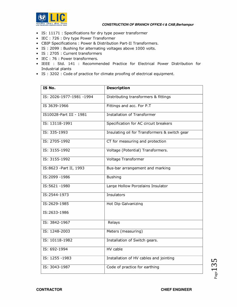
CONSTRUCTION OF BRANCH OFFICE-I & CAB,Berhampur
CONTRACTOR CHIEF ENGINEER
Pa
ge1
35
• IS: 11171 : Specifications for dry type power transformer
• IEC : 726 : Dry type Power Transformer
• CBIP Specifications : Power & Distribution Part-II Transformers.
• IS : 2099 : Bushing for alternating voltages above 1000 volts.
• IS : 2705 : Current transformers
• IEC : 76 : Power transformers.
• IEEE : Std. 141 : Recommended Practice for Electrical Power Distribution for
Industrial plants
• IS : 3202 : Code of practice for climate proofing of electrical equipment.
IS No. Description
IS: 2026-1977-1981 -1994 Distributing transformers & fittings
IS 3639-1966 Fittings and acc. For P.T
IS10028-Part III - 1981 Installation of Transformer
IS: 13118-1991 Specification for AC circuit breakers
IS: 335-1993 Insulating oil for Transformers & switch gear
IS: 2705-1992 CT for measuring and protection
IS: 3155-1992 Voltage (Potential) Transformers.
IS: 3155-1992 Voltage Transformer
IS:8623 -Part II, 1993 Bus-bar arrangement and marking
IS:2099 -1986 Bushing
IS:5621 -1980 Large Hollow Porcelains Insulator
IS:2544-1973 Insulators
IS:2629-1985
IS:2633-1986
Hot Dip Galvanizing
IS: 3842-1967 Relays
IS: 1248-2003 Meters (measuring)
IS: 10118-1982 Installation of Switch gears.
IS: 692-1994 HV cable
IS: 1255 -1983 Installation of HV cables and jointing
IS: 3043-1987 Code of practice for earthing

CONSTRUCTION OF BRANCH OFFICE-I & CAB,Berhampur
CONTRACTOR CHIEF ENGINEER
Pa
ge1
36
IS:13947-Part III-1993 HD Air breaker, Switch gears and fuses voltage not
exceeding 1000 Volts
IS:13703-Part IV-1993 Selection, installation and maintenance of fuses up
to 650 Volts
IS:13947-Part I-1993 General requirements for switch gear and control
gear for voltage not exceeding 1000 volts
IS: 13947-Part III, -1993 Air-break isolators for Voltage not exceeding 1000
Volts
IS:8623-1993 Factory built assemblies of switch gears and
control gears for voltage up to and including 1000
Volts A.C. and 1200 Volts D.C
IS:11353-1985 Marking and arrangement of switch gear bus bars
main connectors and auxiliary wiring
IS: 2147-1962 Cubical Boards.
IS: 8084-1976 Insulated conductor rating
IS: 2675-1983 Enclosed distribution fuse boards and cutouts for
Voltage not exceeding 1000 Volts.
IS: 8828-1995 Miniature Circuit Breaker
IS: 9926-1981 Fuse wire used in rewirable type electric fuses up
to 650 Volts
IS: 1554-Part I, 1998 PVC insulated electric cables Heavy duty
IS: 3961-Part II, 1967 Recommended current rating for cables
IS: 8130-1984 Copper conductor in insulated cables and cores
IS: 8130-1984 Conductor for insulated electric cables and flexible
cords
IS: 3975-1999 Mild steel wires, strips and tapes for armoring
cables
IS: 5831-1984 PVC insulation and sheath of electric cables
IS: 8130-1984 Aluminum conductor for insulated cables
IS: 11955-1987 Recommended current rating for Cable.
IS: 732-1989 Code of practice for electrical wiring installation
system Voltage
not exceeding 650 Volts.

CONSTRUCTION OF BRANCH OFFICE-I & CAB,Berhampur
CONTRACTOR CHIEF ENGINEER
Pa
ge1
37
IS: 1646-1997 Code of practice for fire safety of Buildings
(general) electrical installation
IS: 9537-1981 Rigid steel conduits for electrical wiring
IS: 2667-1988 Fittings for rigid steel conduits for electrical wiring
IS: 3480-1966 Flexible steel conduit for electrical wiring
IS: 3837-1976 Accessories for rigid steel conduits for electrical
wiring
IS: 694-1990 PVC insulated cables (wires).
IS: 9537-Part III, 1983 Rigid non-metallic conduits for electrical wiring
IS: 6946-1973 Flexible (playable) nonmetallic conduits for
electrical installation
IS: 1293-2005 Three pin plugs and sockets
IS: 8130-1984 Conductors for insulated electrical cables and
flexible codes
IS: 9537-1980 Specification for conduit for electrical installation
IS: 3419-1988 Accessories for non-metallic conduits for electrical
wiring
IS: 3854-1997 Switches
IS: 6538-1971 Plugs
IS: 13925-Part I, 1998 Shunt Capacitors for power systems
IS: 9385-1979 HRC cartridge fuse and links up to 660 volts
IS: 1913-1978 General and safety requirement for lighting fittings
IS: 1944-1981 Code of practice for lighting public thorough fares
IS: 3528-1966 Waterproof electric lighting fittings
IS: 3553-1966 Water tight electric lighting fitting
IS: 1239-Part I, 2004 Mild Steel tubular and other wrought steel pipe
fitting
IS: 10322-Part V, 1987 Luminaries for street light
IS: 93703-Part III, 1993 HRC fuses having rupturing capacity of 90 KA

CONSTRUCTION OF BRANCH OFFICE-I & CAB,Berhampur
CONTRACTOR CHIEF ENGINEER
Pa
ge1
38
IS: 2312-1967 Exhaust Fan
IS: 374-1979 Class I Ceiling Fan
IS: 7098 (Part I, II, III), -
1985&86
XLPE armoured Cables
IS:7098 (Part I&II) XLPE armoured Cables
SWITCH GEAR SYTEMS
• IS-2516: Circuit Breakers
• IS-2705: Current Transformer
• IS-3156: Potential Transformer
• IS-9385: High voltage fuses
• IS-6875: Control switches
• IS-1248: Electrical Direct acting indicating instruments
• IS-722: AC electricity Meter of Induction type
• IS-3231: Electrical Relays
• IS-2147: Degree of protection provided by enclosures for low voltage switch gear
and control gears.
• IS-375: Marking and arrangement for switchgear, bus bars, main connection and
auxiliary wiring.
• IS-9224 : Low voltage fuses.
• IEC 62271-1 Common Specifications for Switchgear & Control gear
• IEC 62271-100 Circuit Breakers
• IEC 62271-200 A.C. metal-enclosed switchgear and control gear for rated voltages
above 1kV and up to and including 72kV
• IEC Code herein referred
• IEC 60129 Alternating current disconnectors (isolators)
• IS 2705 Current transformers IS 3156 Voltage transformers
• IEC 60255 Electrical relays
• IEC 60529 Classification of degrees of protection provided by enclosures
• Any other codes recognized in the country of origin of equipment might be
considered provided that they fully comply with Indian Electricity code.
NOMINAL VOLTAGE HT TR - XLPE POWER CABLES
IS:8130 –
1984
Conductors for insulated electric cables and flexible cords.
IS:7098 (Part
2)/ 1985
Cross linked Polyethylene (XLPE) Insulated PVC sheathed cable
for working voltages from 3.3 kV up to and including33kV
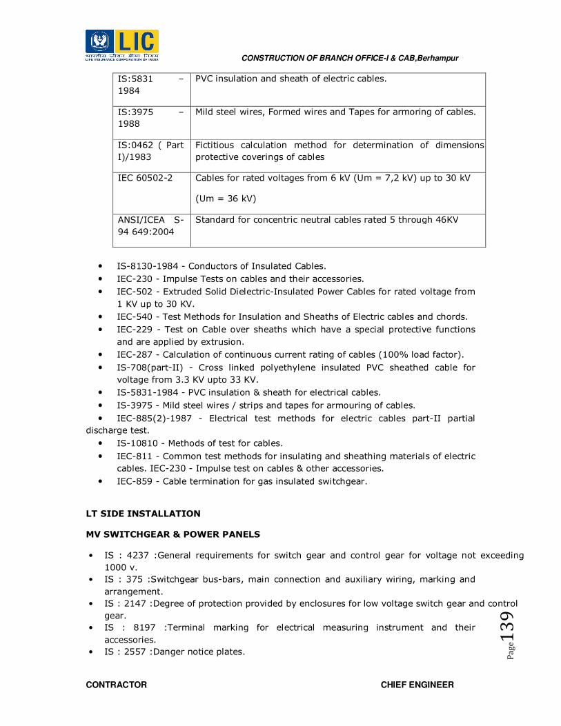
CONSTRUCTION OF BRANCH OFFICE-I & CAB,Berhampur
CONTRACTOR CHIEF ENGINEER
Pa
ge1
39
IS:5831 –
1984
PVC insulation and sheath of electric cables.
IS:3975 –
1988
Mild steel wires, Formed wires and Tapes for armoring of cables.
IS:0462 ( Part
I)/1983
Fictitious calculation method for determination of dimensions of
protective coverings of cables
IEC 60502-2 Cables for rated voltages from 6 kV (Um = 7,2 kV) up to 30 kV
(Um = 36 kV)
ANSI/ICEA S-
94 649:2004
Standard for concentric neutral cables rated 5 through 46KV
• IS-8130-1984 - Conductors of Insulated Cables.
• IEC-230 - Impulse Tests on cables and their accessories.
• IEC-502 - Extruded Solid Dielectric-Insulated Power Cables for rated voltage from
1 KV up to 30 KV.
• IEC-540 - Test Methods for Insulation and Sheaths of Electric cables and chords.
• IEC-229 - Test on Cable over sheaths which have a special protective functions
and are applied by extrusion.
• IEC-287 - Calculation of continuous current rating of cables (100% load factor).
• IS-708(part-II) - Cross linked polyethylene insulated PVC sheathed cable for
voltage from 3.3 KV upto 33 KV.
• IS-5831-1984 - PVC insulation & sheath for electrical cables.
• IS-3975 - Mild steel wires / strips and tapes for armouring of cables.
• IEC-885(2)-1987 - Electrical test methods for electric cables part-II partial
discharge test.
• IS-10810 - Methods of test for cables.
• IEC-811 - Common test methods for insulating and sheathing materials of electric
cables. IEC-230 - Impulse test on cables & other accessories.
• IEC-859 - Cable termination for gas insulated switchgear.
LT SIDE INSTALLATION
MV SWITCHGEAR & POWER PANELS
• IS : 4237 :General requirements for switch gear and control gear for voltage not exceeding
1000 v.
• IS : 375 :Switchgear bus-bars, main connection and auxiliary wiring, marking and
arrangement.
• IS : 2147 :Degree of protection provided by enclosures for low voltage switch gear and control
gear.
• IS : 8197 :Terminal marking for electrical measuring instrument and their
accessories.
• IS : 2557 :Danger notice plates.

CONSTRUCTION OF BRANCH OFFICE-I & CAB,Berhampur
CONTRACTOR CHIEF ENGINEER
Pa
ge1
40
• IS : 2516 :Specification for AC circuit breaker.
• IS : 1818 :Specification for AC isolator and earthing switch.
• IS : 3072 :Code of practice for installation and maintenance of switchgear.
• IS : 8623 :Specification for factory built as symbolize of switch gear and control gear
for voltage up to and including 1000v. A.C.& 1200 v. D.C.
• IS : 8828 :Miniature Circuit Breaker.
• IS : 4064 :Fuse switch and switch fuse unit.
• IS : 9224 :HRC fuse unit.
• IS : 2705 :Current transformer.
• IS : 3155 :Voltage transformer.
• IS : 3231 :Electrical relay for protection.
• IS : 1248 :indicating instrument.
• IS : 722 : Integrating instrument.
• IS : 6875 :Control switches & push buttons.
• IS : 2959 :Auxiliary contactor.
• IS : 1822 :AC motor starters of voltage not exceeding 1000V.
• IS : 13947 :Switch Board General Requirement
WIRING SYSTEMS
• IS : 732 Code of practice for electrical wiring installation (System voltage not
Exceeding 1100 V).
• IS : 1646 Code of practice for fire safety of buildings (General) Electrical installation.
• IS : 9537 Conduits for Electrical installations (Part 1-4)
• IS : 2667 Fittings for rigid steel conduits for electrical wiring.
• IS : 3480 Flexible steel conduits for electrical wiring.
• IS : 3837 Accessories for rigid steel conduit for electrical wiring.
• IS : 694 PVC insulated cables.
• IS : 6946 Flexible (Pliable) non-metallic conduits for electrical installation.
• IS : 1293 Plugs and sockets outlets of rated voltage upto and including 250V.
• IS : 8130 Specifications for conduits for electrical installation.
• IS : 3854 Switches for domestic and similar purposes.
• IS : 3419 Fittings for rigid non-metallic conduits.
• IS : 4648 Guide for electrical layout in residential building.
• IS : 4649 Adopters for flexible steel conduits.
• IS : 5133 Boxes for enclosures of the Electrical.
• IS : 4615 Switch socket outlets.
• IS : 8884 Code of practice for installation of Electric bells and call system.
• IS : 2551 Electric Danger notice plates.
• IS : 3646 Code of practice for interior illumination.
• IS : 371 Ceiling Roses.
• IS : 302 General and safety requirements for household and similar electrical
appliances.
• IS : 3043 Code of practice for earthing.
• IS : 5216 Guide for safety procedures and practices in electrical work. Indian
Electricity Act and Rules. Regulations for the electrical equipment in buildings issued
by the concerned Electrical Authorities.
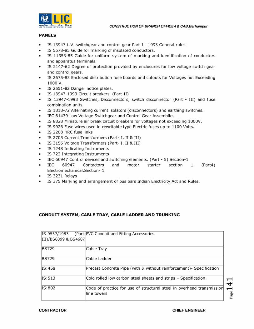
CONSTRUCTION OF BRANCH OFFICE-I & CAB,Berhampur
CONTRACTOR CHIEF ENGINEER
Pa
ge1
41
PANELS
• IS 13947 L.V. switchgear and control gear Part-I - 1993 General rules
• IS 5578-85 Guide for marking of insulated conductors.
• IS 11353-85 Guide for uniform system of marking and identification of conductors
and apparatus terminals.
• IS 2147-62 Degree of protection provided by enclosures for low voltage switch gear
and control gears.
• IS 2675-83 Enclosed distribution fuse boards and cutouts for Voltages not Exceeding
1000 V.
• IS 2551-82 Danger notice plates.
• IS 13947-1993 Circuit breakers. (Part-II)
• IS 13947-1993 Switches, Disconnectors, switch disconnector (Part - III) and fuse
combination units.
• IS 1818-72 Alternating current isolators (disconnectors) and earthing switches.
• IEC 61439 Low Voltage Switchgear and Control Gear Assemblies
• IS 8828 Miniature air break circuit breakers for voltages not exceeding 1000V.
• IS 9926 Fuse wires used in rewritable type Electric fuses up to 1100 Volts.
• IS 2208 HRC fuse links
• IS 2705 Current Transformers (Part- I, II & III)
• IS 3156 Voltage Transformers (Part- I, II & III)
• IS 1248 Indicating Instruments
• IS 722 Integrating Instruments
• IEC 60947 Control devices and switching elements. (Part - 5) Section-1
• IEC 60947 Contactors and motor starter section 1 (Part4)
Electromechanical.Section- 1
• IS 3231 Relays
• IS 375 Marking and arrangement of bus bars Indian Electricity Act and Rules.
CONDUIT SYSTEM, CABLE TRAY, CABLE LADDER AND TRUNKING
IS-9537/1983 (Part-
III)/BS6099 & BS4607
PVC Conduit and Fitting Accessories
BS729 Cable Tray
BS729 Cable Ladder
IS:458 Precast Concrete Pipe (with & without reinforcement)- Specification
IS:513 Cold rolled low carbon steel sheets and strips – Specification.
IS:802 Code of practice for use of structural steel in overhead transmission
line towers

CONSTRUCTION OF BRANCH OFFICE-I & CAB,Berhampur
CONTRACTOR CHIEF ENGINEER
Pa
ge1
42
Part II
IS:808 Dimension for hot rolled steel beam, channel and angle sections
IS:1079 Hot rolled carbon steel sheets and strips - Specification
IS:1367
(Part-1)
Technical supply conditions for threaded steel fasteners. :General
requirements for bolts, screws and studs
IS:1367
(Part-13)
Technical supply conditions for threaded steel fastners :Hot dip
galvanised coatings on threaded fasteners.
IS:2062 Steel for general structural purposes - Specification
IS:2629 Recommended practice for hot dip galvanizing of iron and steel.
IS:2633 Method for testing uniformity of coating on zinc coated articles
IS 4759
Hot-Dip Zinc Coatings on Structural Steel and other Allied Products -
Specification
IS:6745 Methods for determination of mass of zinc coating on zinc coated iron
and steel articles.
IS:3063 Fasteners - single coil rectangular section spring lock washers -
Specification.
IS 7318
part-I
Approval test for welders when welding procedure
approval is not required.: Fusion welding of steel
IS 7318
part-II
Approval tests for welders when welding procedure approval is not
required: TIG or MIG welding of aluminum and its alloys
IS 10748 Hot rolled steel strip for welded tubes and pipes – specification.
ASME
(section-IX)
Welding and brazing qualification
WIRES AND CABLES
• IS-3961: Current rating for cables.
• IS-5831: PVC insulation and sheath of electric cables.
• IS-694: PVC insulated cables for working voltage up to and including 1100 volts.
• IEC-54 (I): PVC insulated cable.
• IS: 8130: Conductors for insulated electric cables and flexible cords.
CONSTRUCTION OF BRANCH OFFICE-I & CAB,Berhampur
CONTRACTOR CHIEF ENGINEER
Pa
ge1
43
• IS: 5831: HRPVC / HR PVC insulation and LSZH sheath of electric cables.
• IS: 3975: Mild steel wires, strips and tapes for armoring cables.
• IS: 3961: Current rating of cables.
LOW VOLTAGE SWITCHGEAR AND TESTED ASSEMBLY
• IEC61 439-1 & 2: Low Voltage Switchgear Assemblies
• IEC 60 947 /IS 13947: 1993 Low Voltage switchgear & control gear
• IEC 61641: Internal arc
LIGHTNING PROTECTION SYSTEM
• IS / IEC 62305-3 & IS 3043 IS/ IEC 62561
SPECIFICATIONS FOR LED LIGHT FIXTURES / LUMINAIRES
• IS: 16102-2 : Ballast type LED lamp performance requirement, lamp and
accessories
• IS: 16107-2-1 : Luminaries performance LED luminaries
• IS: 16103-2 : LED modules performance requirements electric lamps and
accessories
• IEC 62031 : LED modules for general lighting safety requirements
• EN 61547 : Equipment for general lighting purpose EMC immunity
requirement
• IEC 60598-2-1 : Fixed general purpose luminaries
• IEC 60598-1 : Luminaries General requirement and tests
• IEC 61000-3-2 : Electro Magnetic compatibility (EMC) Limits for Harmonic current
emission (equipment input current less than or equal
to 16 amps per phase)
• IEC 61347-2-13 : Lamp control gear particular requirement or DC and AC
supplied electronic control gear for LED modules
• IS: 10322 : Specification or the luminaries
• IS: 4905 : Method for random sampling
• LM 79 : LED luminaire photometry measurement
CONSTRUCTION OF BRANCH OFFICE-I & CAB,Berhampur
CONTRACTOR CHIEF ENGINEER
Pa
ge1
44
• LM 80 : Lumen maintenance
• IEC 62384 : DC or AC supplied electronic control gear for LED modules-
performance requirement
• IEC / PAS 62612 : Self ballasted LED lamps for general lighting services
performance requirement
LIFT INSTALLATIONS
List of Indian Standards connected with Lift installations:
IS: 1860 – 1980 : Code of Practice for installation, operation and maintenance of
electric passenger & goods lift.
IS: 6620 – 1972 : Code of Practice for installation, operation and maintenance of
electric service lift.
IS: 4666 – 1968 : Specification of electric passenger & goods lifts
IS: 6383 – 1971 : Electric Service lift
IS: 3534 – 1977 : Outline dimensions for electric lifts
IS: 4591 – 1968 : Code of Practice for installation, operation and maintenance of
escalators.
IS: 2365 – 1977 : Specification for steel wire suspension ropes for lifts and hoists.
IS: 2363 : Glossary of terms relating to wire ropes.
IS: 4289 – 1967 : Specification for lifts cables.
IS: 1591 – 1960 : Glossary of terms for electrical cables & conduits
IS: 434/1 – 1964 : Specification for rubber insulated cable.
IS: 3352 – 1965 : Specification for varnished, cotton cloth & tape for electrical purpose.
IS: 7759 – 1975 : Specification for lift door locking devices and contacts.
IS: 1173 – 1967
(R) : Specification for hot rolled and slit steel bars.
IS: 7443 – 1974 : Method of loading rating of worm gear.

CONSTRUCTION OF BRANCH OFFICE-I & CAB,Berhampur
CONTRACTOR CHIEF ENGINEER
Pa
ge1
45
IS: 7403 – 1974 : Code of Practice for selection of standard work & helical gear box.
IS: 4218/ii –
1967 : Isometrics screw threads.
IS: 2147 – 1962 : Degree of protection provided by enclosure for low voltage switch
gear & control gear.
IS: 2208 – 1962 : Specification for HRC cartridge fuse links upto 650 volts.
IS: 732 – 1963 : Code of Practice for electrical wiring installation (system voltage not
exceeding 650 volts.)
IS: 585 – 1962 : Voltage & frequency for AC transmission & distribution system.
IS: 2959 – 1969 : Specification for AC contractors voltage not exceeding 1000V.
IS: 4047 – 1967 : Heavy duty air break switches & composite units of air break switches
& fuses for voltage not exceeding 1000V.
IS: 4237 – 1967 : General requirements for switchgears and controller for voltage not
exceeding 1000V.
IS: 1822 – 1961 : Specification for motor starter of voltage upto 650V.
IS: 2332 – 1962 : Nomenclature of floors & storey.
IS: 1950 – 1962 : Code of Practice for sound insulation of non-industrial building.
IS: 906 – 1965 : Code of Practice for installing & maintenance of induction motors.
IS: 325 – 1970 : Specification of three phase induction motors (R).
IS: 4029 – 1967 : Guide for testing of three phase induction motors.
IS: 4691 – 1968 : Specification for degree of protection provided by enclosure for
rotating electrical machinery.
IS: 6362 – 1971 : Designation of method of cooling for rotating electrical machines.
IS: 1271 – 1958 : Classification of insulating materials for electrical machinery and
apparatus in relation to their thermal stability in service.
4566:1980
6335: 1971
:
Safety rules for passenger and Goods Lifts
Electric Passenger & Goods Lift.
Electric Service Lifts
IS 2315: 1978 : Thimbles for Wire ropes
IS 2361: 1994 : Bulldog grips ropes
IS 2485: 1979 : Prop. Purged Sockets for wire ropes for General Engineering

CONSTRUCTION OF BRANCH OFFICE-I & CAB,Berhampur
CONTRACTOR CHIEF ENGINEER
Pa
ge1
46
purposes.
IS 3734: 1983 : Dimensions for Warm gearing.
IS 3937: 1974 : Recommendations for Socketing of wire ropes.
IS 4190: 1984 : Eyebolts with Collars
9803: 1981 : Buffers for Electric Passenger and Goods Lifts.
10191: 1982 : Car and Counter weight guide rails, guide rail supports and fastenings
for lifts
11615: 1986 : Car and counter weight guide shoes for electric passenger and goods
lifts.
11706: 1986 : General requirements for Car frame for electric passenger and goods
lift.
9878: 1981 : safety gears and Governors for electric passenger and goods lifts.
10448: 1983 : Retiring Cam for Passenger and Goods Lifts
IS 14665 (Part.2
/ Sec 1) 2000 :
Electric traction Lifts.
a) Code of practice for installation, operation and maintenance
IS 14665 (Part 3
/ Sec. 1 & 2)
2000
: b) Electric traction safety rules
IS 14665
(Part.4/Sec.3)
2000
: c) Components of lifts car frame, car counter weight and suspension
IS 14665
(Part.4/Sec.5)
2000
: d) Lift doors and locking devices and contacts.
The lift installation shall also be governed by the following Acts/Byelaws/Rules/Codes as
amended upto date in addition to standards and codes specified in the tender:
1. National Building Code of India – 1983
2. Indian Electricity Act – 2003
3. Indian Electricity Rule – 1956
4. Bombay Lift Act – 1939
5. Any Govt. Development Control Regulation for Structural Safety against Natural
Hazards.

CONSTRUCTION OF BRANCH OFFICE-I & CAB,Berhampur
CONTRACTOR CHIEF ENGINEER
Pa
ge1
47
AC
LIST OF BUREAU OF INDIAN STANDARDS AND OTHER CODES
• IS : 277 - 1992 Galvanized steel sheet (Plain & Corrugated) wire for fencing.
• IS : 554 - 1985 (Reaffirmed 1996) Dimensions for pipe threads where pressure
tight joints are required on the threads.
• IS : 655 - 1963 (Reaffirmed 1991) Metal air ducts.
• IS : 659 – 1964 (Reaffirmed 1991) Air conditioning (Safety Code)
• IS : 660 – 1963 (Reaffirmed 1991) Mechanical Refrigeration (Safety Code)
• IS : 694 - 1990 (Reaffirmed 1994) PVC insulated (HD) electric cables for working
voltage upto
• and including 1100 volts.
• IS : 732 - 1989 Code of practice for electrical wiring.
• IS : 780 - 1984 Sluice valves for water works purposes.
• IS : 822-1970 (Reaffirmed 1991) Code of procedure for inspection of welds.
• IS : 1239 (Part - I) - 1990 Mild steel tube
• IS : 1239 (Part - II) - 1992 Mild steel Tubulars and other wrought steel pipe
fittings.
• IS : 1255 - 1983 Code of Practice for installation and maintenance of Power
Cables upto and including 33 KV rating (Second Revision)
• IS : 1554 - 1988 (Part – I) PVC insulated ( Heay Duty) electric cables for working
voltages pto and including 1100 volts.
• IS : 1897 - 1983 (Reaffirmed 1991) Copper bus bar / strip for electrical purposes
• IS : 2379 - 1990 Colour code for the identification of pipelines.
• IS : 2551 - 1982 Danger notice plate
• IS : 3043 - 1987 Code of practice for earthing.
• IS : 3103 – 1975 (Reaffirmed 1999) Code of practice for Industrial Ventilation.
• IS : 3837 - 1976 (Reaffirmed 1990) Accessories for rigid steel conduit for
electrical wiring.
• IS : 4736 – 1986 (Reaffirmed 1998) Hot-dip zinc coatings on steel tubes
• : 4894 - 1987 Centrifugal Fan.
• IS : 5133 - 1969 (Part-I) (Reaffirmed 1990) Boxes for the enclosure of electrical
accessories.
• IS : 5216 - 1982 (Part-I) (Reaffirmed 1990) Guide for safety procedure and
practices
• in electrical work.
• IS : 5312 (Part-I) - 1984 (Reaffirmed 1990) Swing - check type reflux Non return
valves for water works
• IS : 5424 – 1989 (Reaffirmed 1994) Rubber mats for electrical purposes.
• IS : 5578 & 11353-1985 Marking and identification of conductors
• IS : 6392 - 1971 (Reaffirmed 1988) Steel pipe flanges.
• IS : 8623 - 1993 Low voltage switchgear and control gear Assemblies
(Requirement for type partly type tested assemblies)
• IS : 8623 - 1993 Bus Bar trunking system (Part - II)
• IS : 8828 - 1996 Circuit Breakers for over current protection For house hold and
similar nstallation.

CONSTRUCTION OF BRANCH OFFICE-I & CAB,Berhampur
CONTRACTOR CHIEF ENGINEER
Pa
ge1
48
• IS : 9537 - 1981 (Part II) Rigid Steel Conduits for electrical wiring
• IS : 10810 - 1988 Methods of test for cables.
• IS : 13947-1993 (Part-I) General rules for low voltage swtich gears and control
gears.
• IS : 13947-1993 (Part-II) Circuit Breakers
• IEC 947 - 2
• IS : 13947 - 1993 (Part-III) Swiches, disconnectors and fuse for low voltage
switch gear and control gear.
• IS : 13947 - 1993 (Part-IV) Low voltage switch gear and control gear for
contactors and motor starters
• IS : 13947 – 1993 (Part-V) Control Circuit Devices.
• BS : EN:779 – 1993 Filters
• ASHRAE Hand Books American Society of Heating Refrigeration & Airconditioning
. application 2007.
• Fundamentals 2005.
• Refrigeration 2006.
• Systems & Equipment 2008.
• ASHRAE Indoor air quality Standard 62.1-2007.
• ASHRAE 90.1-2007
• ASHRAE 55-2004
• ASHRAE 52.1 and 52.2
• IEC Relevant Sections.
• Energy Conservation Building code of India -2008 (BEE)

CONSTRUCTION OF BRANCH OFFICE-I & CAB,Berhampur
CONTRACTOR CHIEF ENGINEER
Pa
ge1
49
CONVENTIONAL FIRE ALARM SYSTEM
• IS 732-1963 Code of Practice for electrical wiring installation (system voltage not
exceeding 650 Volts).
• UL "UNDERWRITERS" laboratory/NFPA/ FM for listed detector, fire panel.
• IS 1584 (Part-I) for PVC insulated copper conductor armoured cable.
• IS 694 PVC insulated copper fkexible wire.
• IS 1653 for M.S Conduits.
• All items and installation shall be according to the Indian Standards. Where these
standards do not exist, they shall conform to the American Standards or other
internationally accepted standard.
CONSTRUCTION OF BRANCH OFFICE-I & CAB,Berhampur
CONTRACTOR CHIEF ENGINEER
Pa
ge1
50
TEST REPORTS /FACTORY TESTING /O LABORTORY TESTING / SITE TESTING OF
ELECTRICAL & MEP INSTALLATION/ MATERIALS
For following test, contractor has to arrange the manufacturers’ certificate, where as
available / test to be carried out at factory in presence of LIC Engineer if desires to attain
and preparation of reports thereof / test to be carried out at site and preparation of reports
etc.
MATERIAL TESTING
The project in charge engineer shall have full power to get any material of work to be tested
by an independent agency at contractor’s expense in order to prove the soundness and
adequacy.
WIRING
After completion of wiring, installation of switches etc., testing shall be done for insulation
resistance as specified in the tender
The following tests shall form a part of the routine tests.
i) Power frequency voltage dry test on each transport unit
ii) Insulation test with 1 kV/1sec on all auxiliary circuits
iii) Resistance measurement of the main circuits of each transport unit
iv) Mechanical testing of the switching devices
v) Timing test of the circuit breaker
vi) Tightness test
Copies of all routine test certificates shall be made available to the purchaser if required.
All ELMCB / RCCB should be tested for overloading, short circuit, earth leakage tripping and
MCBs should be tested for overloading and short circuit tripping.
CABLE
Insulation Resistance:
a) The insulation resistance shall be measured by applying between earth and the whole
system of conductors or any section thereof with all fuses in place and all switches closed
and except in earthed concentric wiring all lamps in position or both poles of the installation
otherwise electrically connected together. A direct current pressure of not less than twice the
working pressure provided that it need not exceed 500 volts for medium voltage circuits.
Where the supply is derived from the three wire (AC or DC) or a poly phase system, the
neutral pole of which is connected to earth either direct or through added resistance, the
working pressure shall be deemed to be that which is maintained between the outer or phase
conductor and the neutral.
b) The insulation resistance measured as above shall not be less than 50, divided by the
number of points on the circuits provided that the whole installation shall be required to have
an insulation resistance greater than one mega ohm.
c) Control rheostats, heating and power appliances and electrical signs may, if required, be
disconnected from the circuit during the test, but in that event the insulation resistance
between the case of frame work and all live parts or each rheostat appliance and sign shall
not be less than that specified in the relevant IS specifications shall not be less than half a
megohm.
d) The insulation resistance shall also be measured between all conductors connected to one
or phase conductor of the supply and all the conductors connected to the middle wire or the

CONSTRUCTION OF BRANCH OFFICE-I & CAB,Berhampur
CONTRACTOR CHIEF ENGINEER
Pa
ge1
51
neutral or to the other pole or phase conductors of the supply and its value shall not be less
than that specified in sub clause(b).
e) On completion of an electric installation (or an extension to an installation) a certificate
shall be furnished by the contractor countersigned by the qualified supervisor where the
installation was carried out.
Testing of earth continuity path: The earth continuity conductor including metal conduits and
metallic envelopes of cables in all cases shall be tested for electric continuity and the
electrical resistance of the same along with the earthing lead but excluding any added
resistance or earth leakage circuit-breaker measured from the connection with the earth
electrode to any point in the earth continuity conductor in the completed installation shall not
exceed one ohm.
Testing of polarity of non-linked single pole switches:
a) In a two wire installation a test shall be made to verify that all non-linked single pole
switches have been fitted in the same conductor throughout and such conductor shall be
labeled or marked for connection to an outer of phase conductor or to the non-earthed
conductor of the supply.
b) In a three wire or a four wire installation, a test shall be made to verify that every non-
linked single pole switch is fitted in a conductor which is labeled or marked for connection
to one of the outer or phase conductor of the supply.
Testing :
Before energizing , the megger test shall be carried out for insulation resistance between
phase to phase and phase to earth.
For cable up to 1.1KV grade 1000 KV megger shall be used.
D.C. High Voltage test shall be conducted after installation on the following and test results
are recorded as per format furnished by the Engineer-in-charge.
a) All 1000 Volts grade cables in which straight through joints have been made.
b) All cables above 1100 V grade.
For record purposes test data shall include the measure values of leakage current verses
time.
Cables shall be installed in final position with all the straight through joints complete.
Termination shall be kept on unfinished so that the motors, switchgears, t transformers, etc..
are not subjected to test Voltages.
The Test Voltage shall be as under:
i) for cable 1.1 KV Grade 2.0 KV DC
ii) for cable 3.3 KV Grade 5.4 KV DC
iii) for cable 6.6 KV Grade 10.8 KV DC
iv) for cable 11 KV Grade 18 KV DC
1.1 KV XLPE (CROSS - LINKED POLYETHYLENE ) INSULATED POWER CABLES
Should the Engineer require it, the Contractor shall submit reports issued by a approved
testing authority on type test that have been successfully performed on the cable for his
approval. The type test shall include the following test:
Partial discharge test;
• Bending test, plus partial discharge test;
• Tan measurement as a function of the voltage and capacitance measurement;
• Tan measurement as a function of the temperature;
• Heating cycle test plus partial discharge test ;
• Impulse withstand test, followed by a power frequency voltage test;
• Medium-voltage alternating current test;

CONSTRUCTION OF BRANCH OFFICE-I & CAB,Berhampur
CONTRACTOR CHIEF ENGINEER
Pa
ge1
52
• Type test (non-electrical) as stipulated in IEC 502, Table VI.
• Cable routine test shall be conducted at factory in accordance with IEC 502 for the
following tests:
• Measurement of the electrical resistance of conductors
• Partial discharge test,
• 4-hour HT test
Site Acceptance Test
The Contractor shall supply all necessary testing equipments for site testing. When required,
these testing equipments shall be calibrated at the expense of the Contractor at a recognized
national laboratory.
The Contractor shall engage an Authorised Medium Voltage Testing Engineer who is
recognized by SEB to perform all site tests.In addition to SEB’s requirements and those
recommended by the manufacturer, the following tests shall be carried out:
• Continuity test
• Earth test
• Polarity test
• Insulation resistance test
• DC high voltage test. The test voltage shall be in accordance with SEB’s requirements
and Engineer’s approval.
Test for conductors.
• Annealing test (For copper).
• Tensile test (For Aluminum).
• Wrapping test (For Aluminum).
• Resistance test.
• Test of armoring / strips
Test for insulation and sheath.
Physical Test for insulation.
• Tensile strength and elongation at break.
• Aging in air oven.
• Hot set test.
• Shrinkage test.
• Water absorption test. (Gravimetric).
Physical test for outer sheath.
• Tensile strength and elongation at break.
• Aging in air oven.
• Loss of mass in air oven.
• Shrinkage test.
• Hot deformation.
• Heat shock test.
• Thermal stability.
Insulation Resistance (Volume resistively test).
• High voltage test.
• Flammability test
Acceptance test.
The following shall constitute Acceptance test.
• Annealing test (For copper).
• Tensile test (For Aluminum).
• Wrapping test (For Aluminum).
• Conductor Resistance tests.

CONSTRUCTION OF BRANCH OFFICE-I & CAB,Berhampur
CONTRACTOR CHIEF ENGINEER
Pa
ge1
53
• Test for thickness of insulation and sheath.
• Hot set test for insulation.
• Tensile strength and elongation at break for insulation and sheath.
• High voltage Test and insulation (Volume resistively)
• Cold bend test for outer sheath.
• Cold impact test for outer sheath.
• Resistance test for armor
Sampling plan for acceptance test shall be as per IS 7098 Part 1 with latest revisions
Routine test.
The following shall constitute the routine test.
• Conductor resistance test.
• High voltage test.
Once the cable is laid, following tests shall be conducted in presence of the departmental
representatives authorized by Engineer – In – Charge, before energizing the cable.
1. Insulation resistance test (Sectional and Overall).
2. Sheathing continuity test.
3. Continuity and conductor resistance test.
4. Earth test.
5. High voltage test.
6. Teat conducted shall be as per Indian standard and National Electrical code
LT PANEL
TESTS AND INSPECTION
The distribution boards shall be subjected to routine test as per IS: 8623. Vendor has to
arrange for the Test Reports.
Following routine / acceptance and types shall be done at factory.
The panels shall be checked and tested after fabrication, assembling and wiring at factory as
per the following:
Checks
1. Manufacturer of panel as per the agreement Technical Particular, SLD, SOQ/BOQ and
related specifications.
2. Compliance of using approved makes.
3. Manufactured as per approved drawings.
4. Inspection for any damages.
Tests
The following are the routine tests:
a) Measurement of resistance of the main circuits
b) Operation tests
c) One minute power frequency voltage dry withstand tests on the circuit breakers
d) One minute power frequency voltage dry withstand tests on auxiliary circuit.
e) Functional test for all safety and control.
TYPE TESTS
The type test certificate as per IS for similar panel shall be submitted.
SITE TESTS
CONSTRUCTION OF BRANCH OFFICE-I & CAB,Berhampur
CONTRACTOR CHIEF ENGINEER
Pa
ge1
54
In addition to the tests at manufacturer’s premises, all relevant pre-commissioning checks
and tests as well as relay co-ordination from upstream to downstream as per applicable
electrical load shall be done at site before energizing the switch board.
Following shall be minimum checks/tests to be done at site.
a) Physical inspection for breakages/damages /orderliness.
b) Insulation resistance test with 5 KV meggar.
c) Earth continuity test
d) Tightness of joints / connections / terminations.
e) Safety checks
f) General operation / performance checks
g) All test results are to be recorded and reports should be submitted to the department.
CALIBRATIONS
All the protective relays shall be calibrated and test certificate shall be submitted.
TEST CERTIFICATES
Following test certificates shall be submitted by the agency:
a) Test certificate for the routine / acceptance tests.
b) Test certificate for the type tests such as temperature rise test, short circuit withstand
test, degree of protection for similar panels.
c) Test certificates for the calibrations.
MEDIUM/ HV VOLTAGE PANELS
TESTING
The power control centers shall be tested at factory after assembling of all components and
completion of all interconnections and wiring. Tests shall be conducted in accordance with
the requirements of BS:3659.
Insulation Test
Insulation of the main circuit, i.e. the insulation resistance of each pole to the earth and that
between the poles shall be measured.
Insulation resistance to earth of all secondary wiring should be tested with 1000 Volt
magger. Insulation test shall be carried out both before and after high Voltage test. High
Voltage Test A High Voltage test with 2.5 KV for one minute shall be applied between the
poles and earth. Test shall be carried out on each pole in turn with the remaining poles
earthed, all units raked in position and the breakers closed. Original test certificate shall be
submitted along with panel.
TESTING
The power control centers shall be tested at factory after assembling of all components and
completion of all interconnections and wiring. Tests shall be conducted in accordance with
the requirements of BS:3659.
SHORT CIRCUIT AND TYPE TEST:
Bus way system shall comply with following standards:
IEC 61439-1&6
All type test certificates according to above standards shall be of International Lab of repute
such as CPRI or equivalent.

CONSTRUCTION OF BRANCH OFFICE-I & CAB,Berhampur
CONTRACTOR CHIEF ENGINEER
Pa
ge1
55
Type test certificate shall be produced for validation before ordering for Rated Short Circuit
breaking capacity for 1sec.
Type Test certificates confirming Mechanical Operation and Temp. Rise of Tap Off Box of
similar design in accordance with IEC-61439 are must.
BUS DUCTS & BUS BAR CAHMBERS
Busway manufacturer shall produce a Type Test Report determining Rating of Busway at
Ambient Temp. with no deration. Failure to submit such reports will disqualify the
manufacturer.
A Type Test report confirming Degree of Protection in accordance with IEC 60529 is must.
The type test for IEC-60068 of seismic certificate of green premium product from
independent test house is a must.
Type test reports.
Switchboard configurations offered shall be CPRI /Independent international test house
tested for all the tests as per IEC61439-1 & 2 and internal arc tests as per IEC61641. Copies
of the test certificates shall be submitted with the tender.
Testing At Works
Copies of type test carried out at ACB/ MCCB manufacturers works and routine tests carried
out at the switchboard fabricators shop shall be furnished along with the delivery of the
switchboards. Engineer-in-Charge reserves the right to get the switchboard inspected by
their representative at fabricators works prior to dispatch to site to witness the followings.
Physical variation and dimensional check
Functional check
HV test
IR test
TESTS
Unless otherwise specified, the specifications for testing shall be as follows.
SWITCH GEARS
TESTS & INSPECTIONS
Switchgear shall be subjected to routine tests as per IS 8623. Vendor has to arrange for the
Test Reports.
All meters and other reference devices used for testing shall be valid calibration from reputed
national laboratories / Institutes. Inspection by purchasers shall not be carried out unless the
vendor confirms that equipment is ready for proceeding with the tests.
Shop test shall be witnessed by Engineer-In- Charge or his authorized representative. Prior
notice of minimum 4 weeks shall be given to the inspector for witnessing the tests.
Acceptance tests on completed switchboards shall be as follows:
i) A general visual check shall be carried out. This shall cover measurement of
over all dimension, location, number and type of devices, terminal boxes,
location and connection of terminals etc.
j) Checking of bill of materials as per approved drawing.
k) Checking of operation of various feeders as per approved schematic drawings.
l) Operation check shall be carried out for every control function as per schematic
drawings by manually simulating fault conditions and operation of control
switches/relays etc.
m) Checking of inter-changeability of identical feeders.
CONSTRUCTION OF BRANCH OFFICE-I & CAB,Berhampur
CONTRACTOR CHIEF ENGINEER
Pa
ge1
56
n) Insulation resistance test and value measurement on power and control circuits
before and after high voltage withstand test.
o) High voltage test on power and control circuit as per IS 8623.
p) For equipment bought from other suppliers, certified test reports of tests carried
out at the manufacturers works shall be submitted. Normally all routine tests as
specified in the relevant standards shall be conducted by the sub supplier at its
works and copies of routine test reports shall be furnished.
TYPE TEST
The type test certificates shall be submitted to inspecting officer
The agency shall be CPRI test certificate for similar panel (LT Panels or MCC). Panels
shall be got manufactured by only reputed panel manufacturers having got type
tested by CPRI or other Government testing laboratory on similar panels (LT panel or
MCC) of minimum 50KA fault level with stand capacity and IP protection.
ROUTINE/ACCEPTANCE TESTS
The panels shall be checked and tested after fabrication, assembling and wiring at
factory as per the following.
Tests
5 Insulation resistance test. Wiring test shall be carried with 1000-volt Megger to
ensure adequate insulation resistance. (At manufacturer’s works). While carrying
out the IR test the capacitor banks shall be isolated.
6 H.T. test shall be carried out as per IS at manufacturer’s works.
7 Functional tests.
8 Primary/secondary current injection test for relays if protection relays are supplied
as part of BOQ
SITE TESTS
In addition to the tests at manufacturer’s premises, all relevant pre-commissioning
checks and tests shall be done at site before energizing the panel.
Following shall be the minimum checks/tests to be done at site.
7. Physical inspection for breakages/damages/orderliness.
8. Insulation resistance test with 500 V Megger by isolating the Capacitor bank.
The insulation resistance shall be not less than 100 mega ohms.
9. Earth continuity test.
10. Tightness of joints/connections/terminations.
11. Safety checks.
12. General Operation/Performance Checks
HT CABLES
TESTS AND TESTING FACILITIES:
TYPE TESTS:
CONSTRUCTION OF BRANCH OFFICE-I & CAB,Berhampur
CONTRACTOR CHIEF ENGINEER
Pa
ge1
57
All the type tests in accordance with IS: 7098 (Part 2) - 1985, amended up to date, shall be
performed on cable samples drawn by purchaser. Type tests are required to be carried out
from the first lot of supply on a sample of all sizes of cables ordered for each voltage grade.
In case facilities of any of the type tests are not available at the works of the supplier, then
such type test shall be carried out by the supplier at the independent laboratory at the cost
of supplier. Sample for the type test will be drawn by the purchaser's representative and the
type test will be witnessed by him. In case of other Government recognized laboratories /
Test House valid approved Government certificate shall be enclosed along with test.
ROUTINE TESTS:
All the Routine tests as per IS: 7098 (Part 2) - 1985 amended up to date shall be carried out
on each and every delivery length of cable. The result should be given in test report. Partial
discharge test must be carried out in a fully screened test cell. It is, therefore, absolutely
essential that the manufacturer should have the appropriate type of facility to conduct this
test which is routine test. The details of facility available in the manufacturer's works in this
connection should be given in the bid.
ACCEPTANCE TESTS:
All acceptance tests as per IS: 7098 (Part 2) - 1985 as modified up to date including the
optional test as per above clause and Flammability Test shall be carried out on sample taken
from the delivery lot.
SHORT CIRCUIT TEST:
The contractor shall also undertake to arrange for the short circuit test as a type test on any
one size of each voltage grade i.e on one size of 11 kV, one size of 22 kV and one size of 33
kV earthed grade shielded TR-XLPE cables ordered at a recognized testing center such as
Central Power Research Institute at Bangalore/ Bhopal at the cost of supplier. If facilities for
carrying out short circuit tests are available at the works of the supplier, and provided the
certification procedure is approved by the Purchaser, testing at the supplier's works will be
acceptable. Short Circuit test shall be witnessed by the purchaser's representative.
The short circuit test shall be preceded and followed by the following tests so as to ensure
that the characteristics of the cable remain within the permissible limits even after it is
subjected to the required short circuit rating.
a) Partial Discharge Test.
b) Conductor Resistance Test.
c) High Voltage Test.
The manufactured cable will be acceptable only after such a sample test is successfully
carried out at CPRI or at suppliers works and approved by the Purchaser.
TESTING FACILITIES:
The supplier / tenderer shall clearly state as to what testing facilities are available in the
works of manufacturer and whether the facilities are adequate to carry out type, routine and
acceptance tests mentioned in specified IS. The facilities shall be provided by the bidder to

CONSTRUCTION OF BRANCH OFFICE-I & CAB,Berhampur
CONTRACTOR CHIEF ENGINEER
Pa
ge1
58
purchaser’s representative for witnessing the tests in the manufacturer’s works. If any test
cannot be carried out at manufacturer’s works reason should be clearly stated in the tender.
When requested, a certified test report shall be supplied for production runs of cable. The
report is to include all actual production test values required by the referenced specifications.
The manufacturer should provide the traceability information from cable till the materials
used in the manufacturing.
EARTHING & LIGHTNING
TESTS
In accordance with stipulations of the specifications galvanised steel shall be subjected to
four one minute dips in copper sulphate solution as per IS: 2633.
EARTHINGS
A. The entire earthing installation shall be tested as per requirements of Indian Standard
Specification IS : 3043.
B. The following earth resistance values shall be measured with an approved earth meggar
and recorded.
1. Each earthing station
2. Earthing system as a whole
3. Earth continuity conductors
C. Earth conductor resistance for each earthed equipment shall be measured which shall not
exceed 1 Ohm in each case. This is responsibility of contractor to get the final value for
resistance.
D. Measurements of earth resistance shall be carried out before earth connections are made
between the earth and the object to be earthed.
E. All tests shall be carried out in presence of the consultant
LIGHTNING PROTECTION
• The lightning protection system shall not be in direct contact with underground
metallic service ducts and cab.
• Conductors of the lightning protection system shall not be connected with the
conductors of the safety earthing system above ground level.
• Down conductors shall be cleated on the structures at 600 mm interval.
• Connection between each down conductor and rod electrodes shall be made via test
joint (pad type compression clamp) located approximately 1500 mm above ground
level. The rod electrode shall be further joined with the main earth mat.
• Lightning conductors shall not pass through or run inside G.I. conduits.
All Earth pits developed around the campus shall be tested with Earth Test Megger and the
results shall comply with the latest IE regulations. The Contractor shall ensure the soil
resistivirty if required and develop the earth pits to get the best results ie 1 ohms where
ever GI plate type earthing pit is developed and for Copper plate type earthing this shall be
less than 0.5 ohms. Any extra cost incurred to get the final results shall be borne by the
Contractor.

CONSTRUCTION OF BRANCH OFFICE-I & CAB,Berhampur
CONTRACTOR CHIEF ENGINEER
Pa
ge1
59
BUS DUCTS
INSPECTION AND TESTING:
A. The busduct shall be subjected to routine tests in accordance with the appropriate
standards. The routine tests shall be witnessed by purchaser or by an agency authorized by
the purchaser. Following minimum tests shall be carried out on fully assembled busduct at
bidder's works.
B. Dimensional checks and other physical requirements.
C. HV tests.
D. Insulation test.
E. Heat run test, Not required.
F. MV drop test, if required
BUS TRUNKING
LIST OF TEST TO BE CARRIED OUT
Type Tests: Copies of the following certificates Shall be submitted.
→ Verification of Temperature Rise limits.
→ Verification of dielectric properties.
→ Verification of short circuit strength.
→ Verification of degree of protection.
ROUTINE TESTS
(i) Verification of insulation, resistance.
(ii) Inspection of assembly, interlocks, locks etc.
(iii) Check on wiring if provided.
(iv) Dielectric test.
Certificate
Thebusbar,offullrangeandeachrating,shouldpassfulltypetestsspecifiedinIEC61439Part6(2012).
Thecertificateshallbeissuedbyaniindependenttestingauthority.Aproductsafetymark(e.g.KEMA-
KEUR,ASTADIAMOND,UL)shouldbeontheproductofferinga
visibleassurancetoalloffullproductsafetytesting,factoryinspectionandongoingsurveillance under
independentauthorityto ensuretheongoingsafetyof product.
FIRE ALARM SYSTEM
TESTING
Each of the alarm conditions that the system is required to detect shall be introduced on
the system. Verify the proper receipt and the proper processing of the signal at the FACP
and the correct activation of the control points.
When the system is equipped with optional features, the manufacturer's manual shall be
onsulted to determine the proper testing procedures. This is intended to address such
items as verifying controls performed by individually addressed or grouped devices,
sensitivity monitoring, verification functionality and similar.

CONSTRUCTION OF BRANCH OFFICE-I & CAB,Berhampur
CONTRACTOR CHIEF ENGINEER
Pa
ge1
60
Testing of Lift Installation:
Tests at site:Vendor has to submit the Factory Test reports for the Major items like Motors,
gear Box, Panel, controllers, Ropes, cable, Drive and any other items desired by Engineer In
charge.
(a) Leveling Test:
Accuracy of the floor leveling shall be tested with the lift empty, fully loaded. The lift
shall be run to each floor while traveling both in upward and downward directions and the
actual distance of car floor above, below landing floor shall be measured. In each case there
shall not be any appreciable difference in these measurements for leveling at the floors when
the car is empty and when it is fully loaded.
(b) Safety Gear Tests:
Instantaneous safety gear controlled by a governor should be tested with, contract load and
a contract speed, the governor being operated by hand. Two tests should be made, however,
with wedge clamp or flexible clamp safeties, one with contract load in the car and the other
with 60 kg (equivalent to one person) in the car. The stopping distance obtained should be
compared with the specified figures and the guides, car platform, and safety gear should be
carefully examined afterwards for signs of permanent distortion. Counterweight safety gear
should be tripped by the counter weight governor and the stopping distance noted. In this
case, however the governor tripping speed may exceed that of the car safety governor but
by not more than 10 percent. During the safety gear tests, car speed (from the governor or
the main sheave) should be determined atthe instant or tripping speed with that stated in IS.
The governor jaws and rope should be1 examined for any undue wear.
(c) Contract speed:
This should be measured with contract load in the car, with half load, with no load, and
should not vary from the contract speed by more than 10 percent. The convenient method is
by counting the number of revolutions, made by the sheave or drum in a known time, Chalk
mark on the' sheave or drum and a stop switch will facilitate timing but care must be
exercised to ensure that no acceleration or retardation periods are included. If the roping is 2
to 1 the sheave speed is twice the car speed. Alternatively, the speed can be measured by a
tachometer applied directly to shaft immediately below the sheave.
(d) Lift balance:
After the above test, some of the weight shall be removed until the remaining weights
represent the figures specified. With this condition at half way travel the effort required to
move the lift car in either direction with the help of winding wheel shall be as nearly as can
be judged by the same.
(e) Car and landing doors interlock:
The lift shall not move with any door open. The car door relay contact and the retiring
release cam must be tested. The workings of the door operation and the safety edges and
light equipment if any provided shall also be examined.
(f) Controllers:
The operation of the contactors and interlocks shall be examined and it shall be ascertained
whether all the requirements laid down in the specifications have been met.
(g) Normal terminal stopping switches:
These shall be tested by letting the car run to each terminal landing in turn, first with no load
and then with contract load and by taking measurements, top and bottom over travels can
be ascertained.
(h) Final terminal stopping switches:
The normal terminal stopping switches shall be disconnected for this test. It shall be ensured
that these switches operate before the buffers are engaged.

CONSTRUCTION OF BRANCH OFFICE-I & CAB,Berhampur
CONTRACTOR CHIEF ENGINEER
Pa
ge1
61
(i) Insulation Resistance:
This shall be measured (after removing the electronic PCB's and their connection) between
power and control lines and earth and shall not be less than 5 mega-ohms when measured
with D.C. voltage of 500 volts. The test shall be carried out with contactors so connected
together as to ensure that all parts of every circuit are simultaneously tested.
(j) Earthing:
Earthing continuity of all conduits, switches, casing and similar metal work shall be tested.
(k) Ropes:
The size, number construction and fastenings of the ropes should be carefully examined and
recorded.
(I) Buffers:
The car should be run on to its buffers at contract speed and with contract load in the car to
test whether there is any permanent distortion of. the car or buffers. The counter weight
buffers should be tested similarly. Test report shall be intimated after testing at works.
Related Documents