Liebert® Universal Monitor™ User Manual

Welcome message from author
This document is posted to help you gain knowledge. Please leave a comment to let me know what you think about it! Share it to your friends and learn new things together.
Transcript

Liebert® Universal Monitor™
User Manual

Technical Support Site
If you encounter any installation or operational issues with your product, check the pertinent section ofthis manual to see if the issue can be resolved by following outlined procedures. Visithttps://www.VertivCo.com/en-us/support/ for additional assistance.

TABLE OF CONTENTS
1 Introduction 7
1.1 Methods of Viewing and Configuring the Liebert Universal Monitor 7
1.2 Data Logs 7
1.3 Optional Features 7
1.4 Available Alarms 8
1.5 Outside Enclosure Overview 8
1.6 Typical Configuration 9
1.7 Controller Board Overview 10
1.8 Optional Expansion Board Overview 14
1.9 LED Indicators 15
1.10 LED Indicators - Optional Expansion Board 16
1.11 Typical Sequence 18
2 Installation - Main Board 19
2.1 Installation Considerations 19
2.1.1 Unpacking and Preliminary Inspection 19
2.2 Surface-Mounting the Liebert Universal Monitor 20
2.2.1 Mounting the Panel 20
2.3 Flush-Mounting the Liebert Universal Monitor 21
2.3.1 Mounting the Panel 22
2.4 Connect Power to the Liebert Universal Monitor 22
2.4.1 Input Power Connections - Small Enclosure 23
2.4.2 Termination and Mounting - Large Enclosure 24
2.4.3 Connecting the Battery Pack 26
3 Installation - Optional Expansion Board 27
3.1 Installation Considerations 27
3.1.1 Unpacking and Preliminary Inspection 27
3.2 Surface-Mounting the Optional Expansion Board 28
3.2.1 Mounting the Panel 28
3.3 Flush-Mounting the Optional Expansion Board 29
3.3.1 Mounting the Panel 29
3.4 Input Power Connections - Optional Expansion Board 30
4 Wiring and Connections - Main Board 33
4.1 Wiring Specifications 33
4.2 Connecting Digital Inputs and Digital Outputs 34
4.2.1 Connecting Digital Inputs 35
4.2.2 Connecting Digital Outputs 35
4.2.3 Setting the Digital Output Jumpers 36
4.3 Connecting Analog Inputs 37
4.3.1 Setting the 12VDC/24VDC Analog Power Jumper 38
4.3.2 Connecting the Analog Ground 39
Vertiv | Liebert® Universal Monitor™ User Manual | 3
4.4 Connecting Common Alarm Outputs 40
4.5 EIA422 Liebert SiteScan Web Connector 40
4.6 Communications Connections 42
4.6.1 RS232 Connector 42
4.6.2 Phone Line Connector 42
5 Wiring and Connections - Optional Expansion Board 43
5.1 Wiring Specifications 43
5.2 Connecting Inputs and Outputs 44
5.2.1 Connecting Digital Inputs 44
5.2.2 Connecting Digital Outputs 45
5.2.3 Setting the Digital Output DIP Switches 47
5.3 Connect to the Liebert Universal Monitor 48
5.3.1 Connect EIA485 Connectors to Main Board 48
5.3.2 Enable the Connection via Firmware 49
6 Overview of Menus 51
6.1 Opening Screen Overview 52
6.2 Main Menu Overview 53
6.3 LCD Menu Overview 53
7 View Status Options 55
7.1 View Active Alarms 56
7.1.1 Active Alarms 57
7.2 View Alarm Log 57
7.2.1 Alarm Log 58
7.2.2 Backing Up the Alarm Log (Service Terminal Interface only) 58
7.3 View Event Log 59
7.3.1 Event Log 59
7.3.2 Backing Up the Event Log (Service Terminal Interface only) 60
7.4 View Trend Log 60
7.4.1 Select a Sensor 60
7.4.2 View a Trend Log 61
7.4.3 Backing Up the Trend Log (Service Terminal Interface only) 61
7.5 View Input Status 62
7.5.1 Input Status 62
7.6 View Output Status 63
7.6.1 Output Status 63
7.7 View Pager Numbers 63
7.7.1 Select a Pager 64
7.7.2 View a Pager Number 64
7.7.3 View a Pager PIN 64
8 Silence Alarm & Backup Log Files (Service Terminal Interface) 65
8.1 Silence Alarm (Service Terminal Interface) 65
8.2 Back Up Log Files (Service Terminal Interface only) 65
Vertiv | Liebert® Universal Monitor™ User Manual | 4
9 System and Control Options 67
9.1 Login 67
9.2 Setup System - Overview 70
9.3 Setup System - Setup Input 70
9.3.1 Change Label (Name of Input) 71
9.3.2 Define Input as Normally Open or Normally Closed 71
9.3.3 Define Input as Alarmable or Event 72
9.3.4 Set Up Alarmable Inputs in Latched or Unlatched Mode 72
9.3.5 Set Up Delay Time 73
9.4 Setup System - Setup Common Alarm 73
9.5 Setup System - Setup Sensor 74
9.5.1 Identify the Sensor as Connected 75
9.5.2 Change Sensor Label (Name) 75
9.5.3 Change Units Label 76
9.5.4 Change 4 mA Value 76
9.5.5 Change 20 mA Value 76
9.5.6 Change Offset Value 77
9.5.7 Define Sensor as Alarmable or Event 77
9.5.8 Set Up Alarmable Sensors in Latched or Unlatched Mode 78
9.5.9 Change Low Setpoint 78
9.5.10 Change High Setpoint 79
9.5.11 Set Up Delay Time 79
9.6 Setup System - Setup I/O Matrix 80
9.6.1 Set Up Mapping for a Digital Input 80
9.6.2 Set Up Mapping for an Analog Sensor Input 82
9.7 Setup System - Setup Output 83
9.7.1 Change Label (Name of Output) 83
9.7.2 Define Main Board Output as Normally Open / Closed 84
9.7.3 Set Expansion Board Output by DIP Switch 84
9.7.4 Configure Main Board Output for Loss of Power (“Fail-Safe”) 84
9.8 Setup System - Setup Modem & Pagers 84
9.8.1 Modem Setup - Initialization String 85
9.8.2 Modem Setup - Additional Features (Service Terminal Interface only) 86
9.8.3 Pager Setup - Pager Number and PIN 89
9.8.4 Pager Setup - Communications Check (Service Terminal Interface only) 91
9.9 Setup System - Setup System Info 92
9.9.1 Change Password 93
9.9.2 Change Date & Time/Automatic Daylight Saving Time 94
9.9.3 Setup Site ID 94
9.9.4 Connect Battery 94
9.9.5 Backup and Upload Configuration File (Service Terminal Interface only) 95
9.9.6 Setup Serv Ph Num - Enter Phone Number 96
Vertiv | Liebert® Universal Monitor™ User Manual | 5
9.9.7 Setup Serv Ph Num - Communications Check (Service Terminal Interface only) 98
9.9.8 Factory Defaults 98
9.9.9 Perform Firmware Update (Service Terminal Interface only) 99
9.9.10 Initiate Remote Alarm Test (Service Terminal Interface only) 100
9.10 Setup Exp Board - Optional Expansion Board 101
9.11 Manual Output Ctrl 101
9.12 Clear Alarms & Logs 102
9.12.1 Clear Active Alarms 102
9.12.2 Clear the Alarm Log 103
9.12.3 Clear the Event Log 103
9.12.4 Clear the Trend Logs 103
10 Specifications 105
10.1 Liebert Universal Monitor Specifications 105
10.2 Optional Expansion Board Specifications 106
Appendices 107
Appendix A: Service Terminal Interface 107
Appendix B: Default Settings Quick Reference Guide 117
Vertiv | Liebert® Universal Monitor™ User Manual | 6
1 INTRODUCTIONExtensive capabilities can put the Liebert Universal Monitor at the heart of your protective network. TheLiebert Universal Monitor employs local alarming and remote paging services to keep personnel on-siteand at remote locations apprised of the status of equipment.
The panel can interface with any device that closes an electrical contact or has a 4-20 mA signal. Toimprove process efficiency and troubleshooting, the panel tracks data in three types of logs: alarm, eventand trend. The Liebert Universal Monitor has a local LCD interface and a remote dial-up interface.
Further, the Liebert Universal Monitor can report ambient conditions that might adversely affect thefacility or equipment and also can report alarms and other events, as well as initiate responses to reduceor prevent damage.
When an alarm condition arises, the Liebert Universal Monitor displays alarm information and sounds anaudible alarm; if configured, the panel also sends pager notifications and turns connected devices on oroff. See Typical Sequence on page 18 for a more detailed example.
1.1 Methods of Viewing and Configuring the Liebert Universal Monitor
The Liebert Universal Monitor features remote access through two interfaces that allow users toconfigure the panel, silence alarms, back up logs, and perform many other functions to keep a large orsmall operation running smoothly and safely.
• LCD—liquid crystal display on the front of the panel• Service Terminal Interface—accessible via computer connected directly through an RS232
port or remotely through the Liebert Universal Monitor’s onboard modem
These interfaces permit easy access and configuration of the Liebert Universal Monitor, allowing users toview data, silence alarms and have full access to information stored in the panel, including logs of alarmsand events.
One more interface—Liebert’s SiteScan® Web enterprise monitoring system—is primarily for monitoring,though Liebert SiteScan also provides some configuration functions.
1.2 Data Logs
The three types of data logs—alarm history, event history and trend data of analog sensor readings—canbe viewed on the LCD on the front of the Liebert Universal Monitor and downloaded through onboardcommunications ports.
1.3 Optional Features
An optional Expansion Board, which can be purchased separately, allows you to connect an additional 16digital inputs and eight digital outputs to the Liebert Universal Monitor.
An optional Transformer Module, available only in the large enclosure, converts 115VAC or 230VAC to24VAC.
Vertiv | Liebert® Universal Monitor™ User Manual | 7
1.4 Available Alarms
The alarms available with the Liebert Universal Monitor are:
• Discrete input alarm (for each digital input)• High setpoint• Low setpoint• Battery unplugged• Low battery• Loss of power• Check battery• Internal modem fault
Two additional alarms are available with the optional Expansion Board:
• Expansion board loss of communications• Expansion board restore of communications
1.5 Outside Enclosure Overview
The enclosure for the Liebert Universal Monitor controller board comes in two sizes:
• The large enclosure is designed to accommodate the Transformer Module and futurecomponents, in addition to the controller board.
• The small enclosure is built to hold the controller board only.
Both enclosures are 2-3/4" deep.
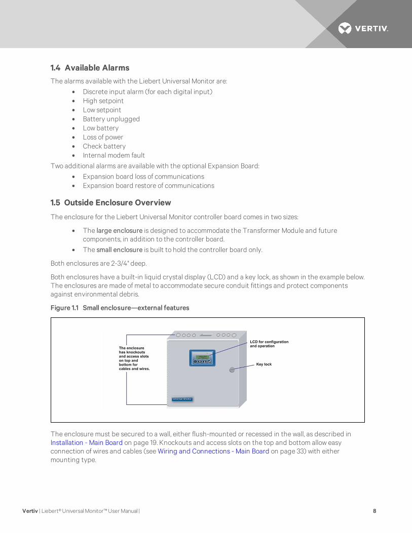
Both enclosures have a built-in liquid crystal display (LCD) and a key lock, as shown in the example below.The enclosures are made of metal to accommodate secure conduit fittings and protect componentsagainst environmental debris.
Figure 1.1 Small enclosure—external features
The enclosure must be secured to a wall, either flush-mounted or recessed in the wall, as described inInstallation - Main Board on page 19. Knockouts and access slots on the top and bottom allow easyconnection of wires and cables (see Wiring and Connections - Main Board on page 33) with eithermounting type.
Vertiv | Liebert® Universal Monitor™ User Manual | 8
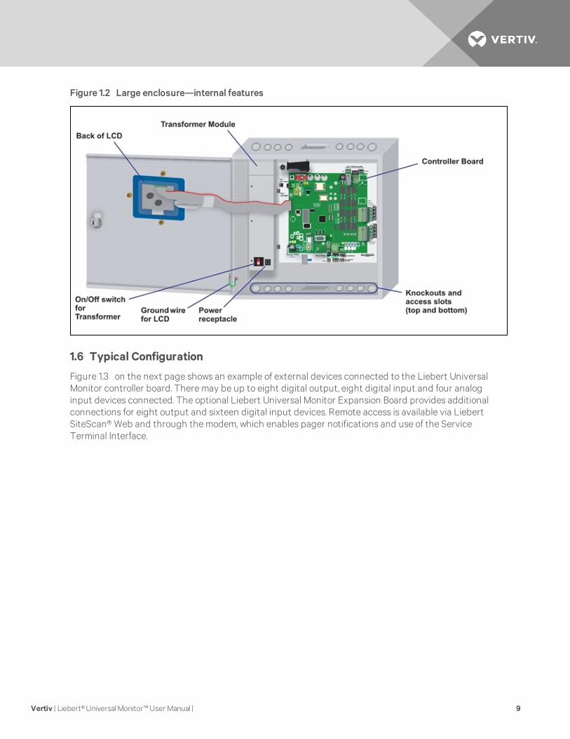
Figure 1.2 Large enclosure—internal features
1.6 Typical Configuration
Figure 1.3 on the next page shows an example of external devices connected to the Liebert UniversalMonitor controller board. There may be up to eight digital output, eight digital input and four analoginput devices connected. The optional Liebert Universal Monitor Expansion Board provides additionalconnections for eight output and sixteen digital input devices. Remote access is available via LiebertSiteScan® Web and through the modem, which enables pager notifications and use of the ServiceTerminal Interface.
Vertiv | Liebert® Universal Monitor™ User Manual | 9
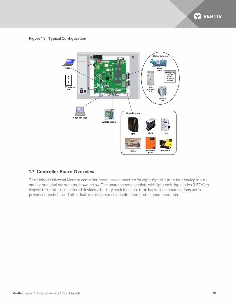
Figure 1.3 Typical Configuration
1.7 Controller Board Overview
The Liebert Universal Monitor controller board has connectors for eight digital inputs, four analog inputsand eight digital outputs, as shown below. The board comes complete with light emitting diodes (LEDs) todisplay the status of monitored devices, a battery pack for short-term backup, communications ports,power connections and other features necessary to monitor and protect your operation.
Vertiv | Liebert® Universal Monitor™ User Manual | 10
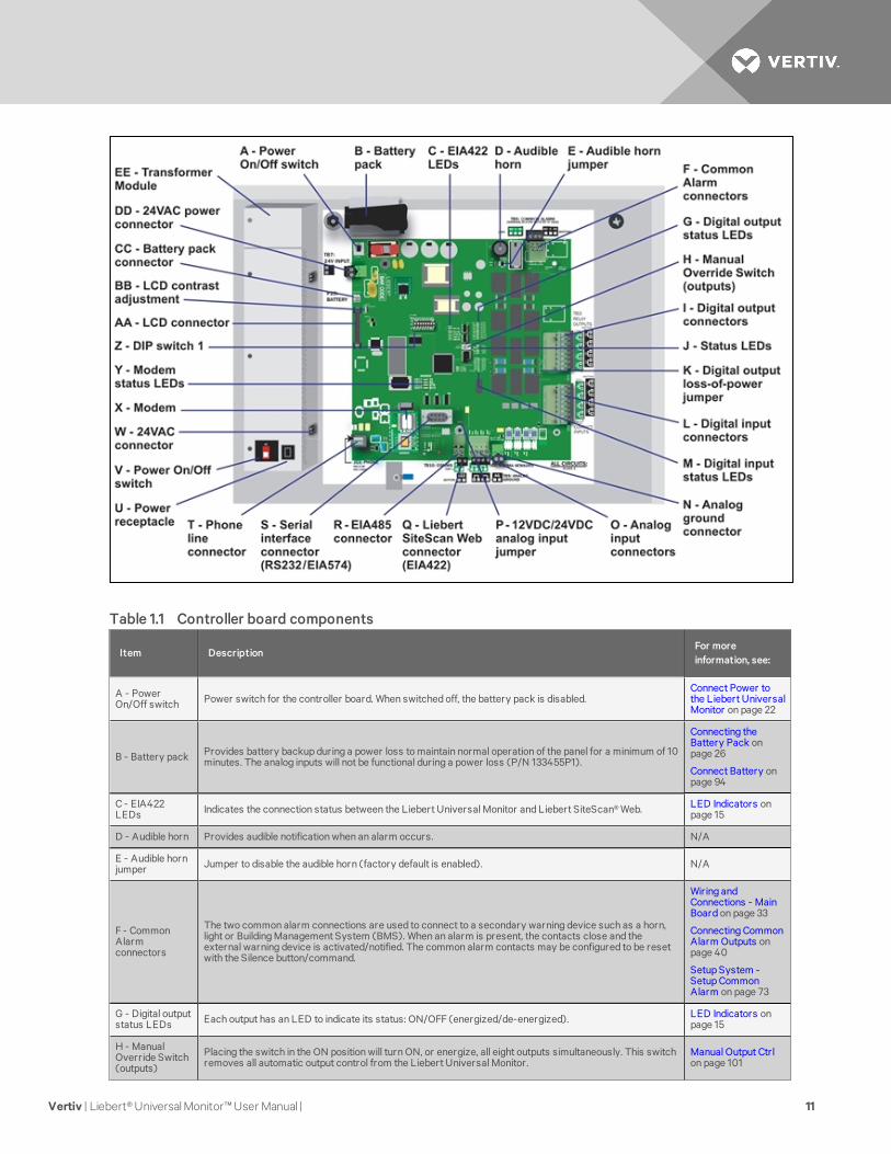
Item DescriptionFor moreinformation, see:
A - PowerOn/Off switch Power switch for the controller board. When switched off, the battery pack is disabled.
Connect Power tothe Liebert UniversalMonitor on page 22
B - Battery pack Provides battery backup during a power loss to maintain normal operation of the panel for a minimum of 10minutes. The analog inputs will not be functional during a power loss (P/N 133455P1).
Connecting theBattery Pack onpage 26
Connect Battery onpage 94
C - EIA422LEDs Indicates the connection status between the Liebert Universal Monitor and Liebert SiteScan® Web. LED Indicators on
page 15
D - Audible horn Provides audible notification when an alarm occurs. N/A
E - Audible hornjumper Jumper to disable the audible horn (factory default is enabled). N/A
F - CommonAlarmconnectors
The two common alarm connections are used to connect to a secondary warning device such as a horn,light or Building Management System (BMS). When an alarm is present, the contacts close and theexternal warning device is activated/notified. The common alarm contacts may be configured to be resetwith the Silence button/command.
Wiring andConnections - MainBoard on page 33
Connecting CommonAlarm Outputs onpage 40
Setup System -Setup CommonAlarm on page 73
G - Digital outputstatus LEDs Each output has an LED to indicate its status: ON/OFF (energized/de-energized). LED Indicators on
page 15
H - ManualOverride Switch(outputs)
Placing the switch in the ON position will turn ON, or energize, all eight outputs simultaneously. This switchremoves all automatic output control from the Liebert Universal Monitor.
Manual Output Ctrlon page 101
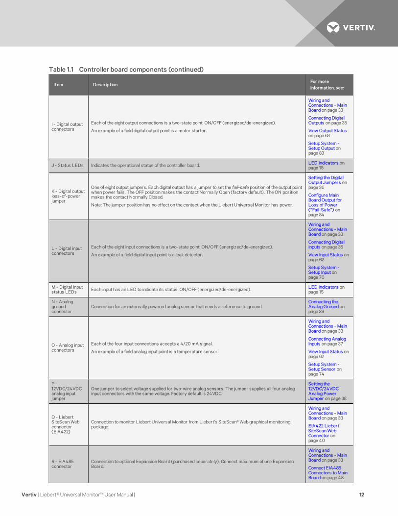
Table 1.1 Controller board components
Vertiv | Liebert® Universal Monitor™ User Manual | 11
Item DescriptionFor moreinformation, see:
I - Digital outputconnectors
Each of the eight output connections is a two-state point: ON/OFF (energized/de-energized).
An example of a field digital output point is a motor starter.
Wiring andConnections - MainBoard on page 33
Connecting DigitalOutputs on page 35
View Output Statuson page 63
Setup System -Setup Output onpage 83
J - Status LEDs Indicates the operational status of the controller board. LED Indicators onpage 15
K - Digital outputloss-of-powerjumper
One of eight output jumpers. Each digital output has a jumper to set the fail-safe position of the output pointwhen power fails. The OFF position makes the contact Normally Open (factory default). The ON positionmakes the contact Normally Closed.
Note: The jumper position has no effect on the contact when the Liebert Universal Monitor has power.
Setting the DigitalOutput Jumpers onpage 36
Configure MainBoard Output forLoss of Power(“Fail-Safe”) onpage 84
L - Digital inputconnectors
Each of the eight input connections is a two-state point: ON/OFF (energized/de-energized).
An example of a field digital input point is a leak detector.
Wiring andConnections - MainBoard on page 33
Connecting DigitalInputs on page 35
View Input Status onpage 62
Setup System -Setup Input onpage 70
M - Digital inputstatus LEDs Each input has an LED to indicate its status: ON/OFF (energized/de-energized). LED Indicators on
page 15
N - Analoggroundconnector
Connection for an externally powered analog sensor that needs a reference to ground.Connecting theAnalog Ground onpage 39
O - Analog inputconnectors
Each of the four input connections accepts a 4/20 mA signal.
An example of a field analog input point is a temperature sensor.
Wiring andConnections - MainBoard on page 33
Connecting AnalogInputs on page 37
View Input Status onpage 62
Setup System -Setup Sensor onpage 74
P -12VDC/24VDCanalog inputjumper
One jumper to select voltage supplied for two-wire analog sensors. The jumper supplies all four analoginput connectors with the same voltage. Factory default is 24VDC.
Setting the12VDC/24VDCAnalog PowerJumper on page 38
Q - LiebertSiteScan Webconnector(EIA422)
Connection to monitor Liebert Universal Monitor from Liebert’s SiteScan® Web graphical monitoringpackage.
Wiring andConnections - MainBoard on page 33
EIA422 LiebertSiteScan WebConnector onpage 40
R - EIA485connector
Connection to optional Expansion Board (purchased separately). Connect maximum of one ExpansionBoard.
Wiring andConnections - MainBoard on page 33
Connect EIA485Connectors to MainBoard on page 48
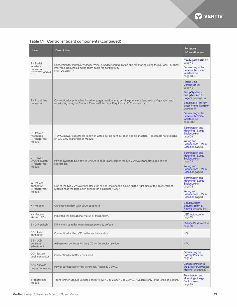
Table 1.1 Controller board components (continued)
Vertiv | Liebert® Universal Monitor™ User Manual | 12
Item DescriptionFor moreinformation, see:
S - Serialinterfaceconnector(RS232/EIA574)
Connection for laptop or video terminal. Used for configuration and monitoring using the Service TerminalInterface. Requires a null modem cable for connectivity(P/N 201258P1).
RS232 Connector onpage 42
Connecting to theService TerminalInterface onpage 109
T - Phone lineconnector
Connection for phone line. Used for pager notifications, service phone number, and configuration andmonitoring using the Service Terminal Interface. Requires an RJ11 connector.
Phone LineConnector onpage 42
Setup System -Setup Modem &Pagers on page 84
Setup Serv Ph Num -Enter Phone Numberon page 96
Connecting to theService TerminalInterface onpage 109
U - Powerreceptacle(TransformerModule)
115VAC power receptacle to power laptop during configuration and diagnostics. Receptacle not availableon 230VAC Transformer Module.
Termination andMounting - LargeEnclosure onpage 24
Wiring andConnections - MainBoard on page 33
V - PowerOn/Off switch(TransformerModule)
Power switch to turn power On/Off to both Transformer Module 24VAC connectors and powerreceptacle.
Termination andMounting - LargeEnclosure onpage 24
Wiring andConnections - MainBoard on page 33
W - 24VACconnector(TransformerModule)
One of the two 24VAC connectors for power (the second is also on the right side of the TransformerModule near the top). Each connector is rated for 40VA.
Termination andMounting - LargeEnclosure onpage 24
Wiring andConnections - MainBoard on page 33
X - Modem On-board modem with 9600 baud rate.Setup System -Setup Modem &Pagers on page 84
Y - Modemstatus LEDs Indicates the operational status of the modem. LED Indicators on
page 15
Z - DIP switch 1 DIP switch used for resetting password to default. Change Password onpage 93
AA - LCDconnector Connection for the LCD on the enclosure door. N/A
BB - LCDcontrastadjustment
Adjustment contrast for the LCD on the enclosure door. N/A
CC - Batterypack connector Connection for battery pack lead.
Connecting theBattery Pack onpage 26
DD - 24VACpower connector Power connection for the controller. Requires 24VAC.
Connect Power tothe Liebert UniversalMonitor on page 22
EE -TransformerModule
Transformer Module used to convert 115VAC or 230VAC to 24VAC. Available only in the large enclosure.
Termination andMounting - LargeEnclosure onpage 24
Table 1.1 Controller board components (continued)
Vertiv | Liebert® Universal Monitor™ User Manual | 13
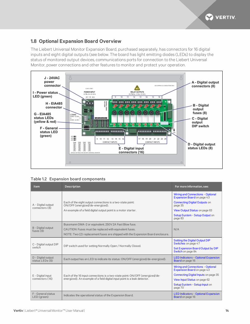
1.8 Optional Expansion Board Overview
The Liebert Universal Monitor Expansion Board, purchased separately, has connectors for 16 digitalinputs and eight digital outputs (see below. The board has light emitting diodes (LEDs) to display thestatus of monitored output devices, communications ports for connection to the Liebert UniversalMonitor, power connections and other features to monitor and protect your operation.
Item Description For more information, see:
A - Digital outputconnectors (8)
Each of the eight output connections is a two-state point:ON/OFF (energized/de-energized).
An example of a field digital output point is a motor starter.
Wiring and Connections - OptionalExpansion Board on page 43
Connecting Digital Outputs onpage 35
View Output Status on page 63
Setup System - Setup Output onpage 83
B - Digital outputfuses (8)
Bussmann GMA-2 or equivalent. 250V 2A Fast Blow fuse.
CAUTION: Fuses must be replaced with equivalent fuses.
NOTE: Two (2) replacement fuses are shipped with the Expansion Board enclosure.
N/A
C - Digital output DIPswitch DIP switch used for setting Normally Open / Normally Closed.
Setting the Digital Output DIPSwitches on page 47
Set Expansion Board Output by DIPSwitch on page 84
D - Digital outputstatus LEDs (8) Each output has an LED to indicate its status: ON/OFF (energized/de-energized). LED Indicators - Optional Expansion
Board on page 16
E - Digital inputconnectors (16)
Each of the 16 input connections is a two-state point: ON/OFF (energized/de-energized). An example of a field digital input point is a leak detector.
Wiring and Connections - OptionalExpansion Board on page 43
Connecting Digital Inputs on page 35
View Input Status on page 62
Setup System - Setup Input onpage 70
F - General statusLED (green) Indicates the operational status of the Expansion Board. LED Indicators - Optional Expansion
Board on page 16
Table 1.2 Expansion board components
Vertiv | Liebert® Universal Monitor™ User Manual | 14
Item Description For more information, see:
G - EIA485 statusLEDs (yellow & red)
Two LEDs indicate status of the EIA485 connection: ON/OFF (energized/de-energized).
LED Indicators - Optional ExpansionBoard on the next page
H - EIA485 connector Connection to the Liebert Universal Monitor.
Connect EIA485 Connectors to MainBoard on page 48
Setup Exp Board - OptionalExpansion Board on page 101
I - Power status LED(green) Indicates the power status of the Expansion Board. LED Indicators - Optional Expansion
Board on the next page
J - 24VAC powerconnector Power connection for the Expansion Board. Requires 24VAC.
View Output Status on page 63
Input Power Connections - OptionalExpansion Board on page 30
Table 1.2 Expansion board components (continued)
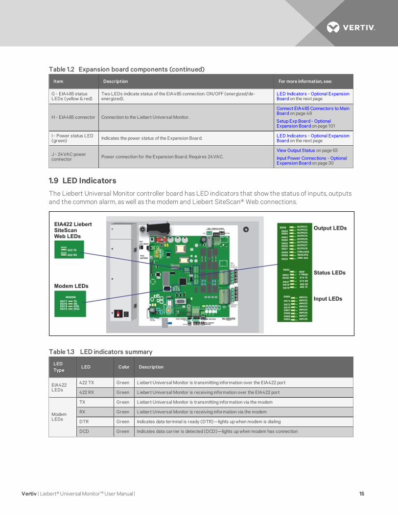
1.9 LED Indicators
The Liebert Universal Monitor controller board has LED indicators that show the status of inputs, outputsand the common alarm, as well as the modem and Liebert SiteScan® Web connections.
LEDType
LED Color Description
EIA422LEDs
422 TX Green Liebert Universal Monitor is transmitting information over the EIA422 port
422 RX Green Liebert Universal Monitor is receiving information over the EIA422 port
ModemLEDs
TX Green Liebert Universal Monitor is transmitting information via the modem
RX Green Liebert Universal Monitor is receiving information via the modem
DTR Green Indicates data terminal is ready (DTR)—lights up when modem is dialing
DCD Green Indicates data carrier is detected (DCD)—lights up when modem has connection
Table 1.3 LED indicators summary
Vertiv | Liebert® Universal Monitor™ User Manual | 15
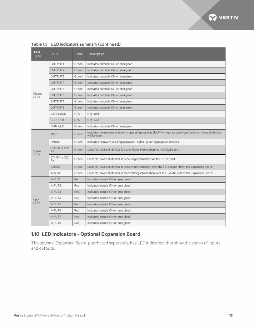
LEDType
LED Color Description
OutputLEDs
OUTPUT1 Green Indicates output is ON or energized
OUTPUT2 Green Indicates output is ON or energized
OUTPUT3 Green Indicates output is ON or energized
OUTPUT4 Green Indicates output is ON or energized
OUTPUT5 Green Indicates output is ON or energized
OUTPUT6 Green Indicates output is ON or energized
OUTPUT7 Green Indicates output is ON or energized
OUTPUT8 Green Indicates output is ON or energized
CTRLLOCK N/A Not used
SENLOCK N/A Not used
CMN ALR Green Indicates output is ON or energized
StatusLEDs
MOP Green Indicates the microprocessor is operating properly (MOP)—must be on before Liebert Universal Monitorwill function
FPROG Green Indicates firmware is being upgraded—lights up during upgrade process
574 TX or 232TX Green Liebert Universal Monitor is transmitting information via the RS232 port
574 RX or 232RX Green Liebert Universal Monitor is receiving information via the RS232 port
485 RX Green Liebert Universal Monitor is receiving information over the EIA485 port from the Expansion Board
485 TX Green Liebert Universal Monitor is transmitting information over the EIA485 port to the Expansion Board
InputLEDs
INPUT1 Red Indicates input is ON or energized
INPUT2 Red Indicates input is ON or energized
INPUT3 Red Indicates input is ON or energized
INPUT4 Red Indicates input is ON or energized
INPUT5 Red Indicates input is ON or energized
INPUT6 Red Indicates input is ON or energized
INPUT7 Red Indicates input is ON or energized
INPUT8 Red Indicates input is ON or energized
Table 1.3 LED indicators summary (continued)
1.10 LED Indicators - Optional Expansion Board
The optional Expansion Board, purchased separately, has LED indicators that show the status of inputsand outputs.
Vertiv | Liebert® Universal Monitor™ User Manual | 16
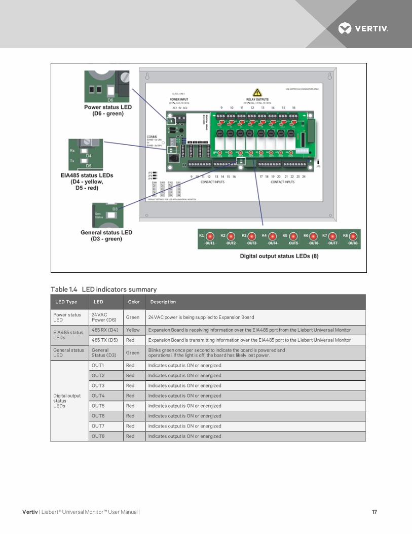
LED Type LED Color Description
Power statusLED
24VACPower (D6) Green 24VAC power is being supplied to Expansion Board
EIA485 statusLEDs
485 RX (D4) Yellow Expansion Board is receiving information over the EIA485 port from the Liebert Universal Monitor
485 TX (D5) Red Expansion Board is transmitting information over the EIA485 port to the Liebert Universal Monitor
General statusLED
GeneralStatus (D3) Green Blinks green once per second to indicate the board is powered and
operational. If the light is off, the board has likely lost power.
Digital outputstatusLEDs
OUT1 Red Indicates output is ON or energized
OUT2 Red Indicates output is ON or energized
OUT3 Red Indicates output is ON or energized
OUT4 Red Indicates output is ON or energized
OUT5 Red Indicates output is ON or energized
OUT6 Red Indicates output is ON or energized
OUT7 Red Indicates output is ON or energized
OUT8 Red Indicates output is ON or energized
Table 1.4 LED indicators summary
Vertiv | Liebert® Universal Monitor™ User Manual | 17
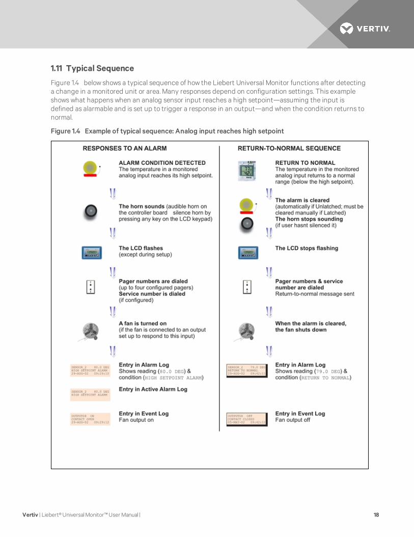
1.11 Typical Sequence
Figure 1.4 below shows a typical sequence of how the Liebert Universal Monitor functions after detectinga change in a monitored unit or area. Many responses depend on configuration settings. This exampleshows what happens when an analog sensor input reaches a high setpoint—assuming the input isdefined as alarmable and is set up to trigger a response in an output—and when the condition returns tonormal.
Figure 1.4 Example of typical sequence: Analog input reaches high setpoint
Vertiv | Liebert® Universal Monitor™ User Manual | 18
2 INSTALLATION - MAIN BOARDThis section provides instructions for installing, mounting and connecting power to the Liebert UniversalMonitor. For information on the optional Expansion Board, see Installation - Optional Expansion Board onpage 27.
2.1 Installation Considerations
The Liebert Universal Monitor must be installed indoors and may be mounted on the surface of a wall orflush-mounted, depending on the user’s application, the location of equipment and sensors to bemonitored and the type of wall the unit will be mounted on.
The Liebert Universal Monitor should be mounted where it can be easily accessed. On-site personnelwould access the unit through the LCD on its front cover, service terminal connected to the RS232 port orthrough Liebert SiteScan®. For off-site monitoring, the Liebert Universal Monitor should be placed nearcommunications means such as a telephone line connection that would permit remote access.
In addition to the communications connections, the site also must have electrical service and must permitconnecting the unit’s eight digital inputs, eight digital outputs and four analog inputs.
The wall material must be capable of supporting the weight of the Liebert Universal Monitor: seeSpecifications on page 105.
NOTE: This equipment has been tested and found to comply with the limits for a Class A digital device,pursuant to part 15 of the FCC rules. These limits are designed to provide reasonable protectionagainst harmful interference when the equipment is operated in a commercial environment. Thisequipment generates, uses, and can radiate radio frequency energy and, if not installed and used inaccordance with the instruction manual, may cause harmful interference to radio communications.Operation of this equipment in a residential area is likely to cause harmful interference in which casethe user will be required to correct the interference at his own expense.
2.1.1 Unpacking and Preliminary Inspection
• Before unpacking the Liebert Universal Monitor, inspect the shipping carton for damage orsigns of mishandling, such as gashes or holes in the carton or severely flattened corners.
• Open the shipping crates carefully. Use care to avoid puncturing the container with sharpobjects that might damage the contents.
• Inspect the Liebert Universal Monitor and all included components for damage.
• If any damage from shipping or mishandling is observed, immediately file a damage claim withthe shipping agency and forward a copy to:
Vertiv™1050 Dearborn DriveP.O. Box 29186Columbus, OH 43229
Vertiv | Liebert® Universal Monitor™ User Manual | 19
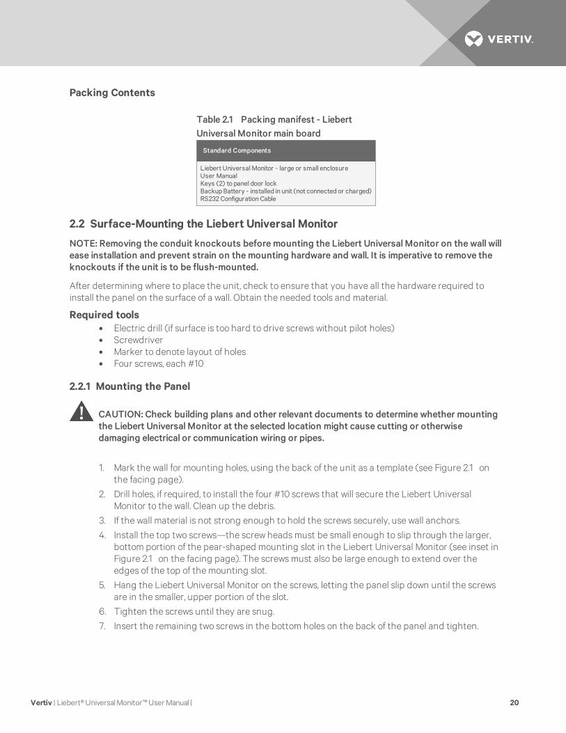
Packing Contents
Standard Components
Liebert Universal Monitor - large or small enclosureUser ManualKeys (2) to panel door lockBackup Battery - installed in unit (not connected or charged)RS232 Configuration Cable
Table 2.1 Packing manifest - LiebertUniversal Monitor main board
2.2 Surface-Mounting the Liebert Universal Monitor
NOTE: Removing the conduit knockouts before mounting the Liebert Universal Monitor on the wall willease installation and prevent strain on the mounting hardware and wall. It is imperative to remove theknockouts if the unit is to be flush-mounted.
After determining where to place the unit, check to ensure that you have all the hardware required toinstall the panel on the surface of a wall. Obtain the needed tools and material.
Required tools• Electric drill (if surface is too hard to drive screws without pilot holes)• Screwdriver• Marker to denote layout of holes• Four screws, each #10
2.2.1 Mounting the Panel
CAUTION: Check building plans and other relevant documents to determine whether mountingthe Liebert Universal Monitor at the selected location might cause cutting or otherwisedamaging electrical or communication wiring or pipes.
1. Mark the wall for mounting holes, using the back of the unit as a template (see Figure 2.1 onthe facing page).
2. Drill holes, if required, to install the four #10 screws that will secure the Liebert UniversalMonitor to the wall. Clean up the debris.
3. If the wall material is not strong enough to hold the screws securely, use wall anchors.
4. Install the top two screws—the screw heads must be small enough to slip through the larger,bottom portion of the pear-shaped mounting slot in the Liebert Universal Monitor (see inset inFigure 2.1 on the facing page). The screws must also be large enough to extend over theedges of the top of the mounting slot.
5. Hang the Liebert Universal Monitor on the screws, letting the panel slip down until the screwsare in the smaller, upper portion of the slot.
6. Tighten the screws until they are snug.
7. Insert the remaining two screws in the bottom holes on the back of the panel and tighten.
Vertiv | Liebert® Universal Monitor™ User Manual | 20
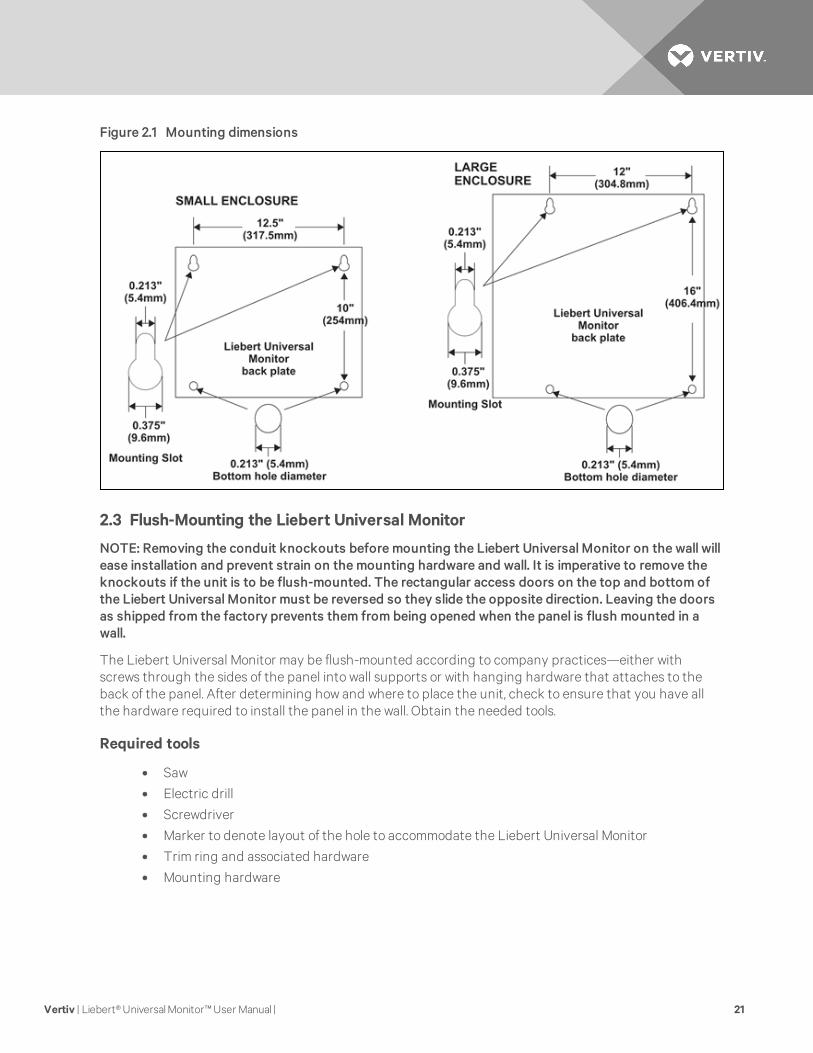
Figure 2.1 Mounting dimensions
2.3 Flush-Mounting the Liebert Universal Monitor
NOTE: Removing the conduit knockouts before mounting the Liebert Universal Monitor on the wall willease installation and prevent strain on the mounting hardware and wall. It is imperative to remove theknockouts if the unit is to be flush-mounted. The rectangular access doors on the top and bottom ofthe Liebert Universal Monitor must be reversed so they slide the opposite direction. Leaving the doorsas shipped from the factory prevents them from being opened when the panel is flush mounted in awall.
The Liebert Universal Monitor may be flush-mounted according to company practices—either withscrews through the sides of the panel into wall supports or with hanging hardware that attaches to theback of the panel. After determining how and where to place the unit, check to ensure that you have allthe hardware required to install the panel in the wall. Obtain the needed tools.
Required tools
• Saw
• Electric drill
• Screwdriver
• Marker to denote layout of the hole to accommodate the Liebert Universal Monitor
• Trim ring and associated hardware
• Mounting hardware
Vertiv | Liebert® Universal Monitor™ User Manual | 21
2.3.1 Mounting the Panel
CAUTION: Check building plans and other relevant documents to determine whether mountingthe Liebert Universal Monitor at the selected location might cause cutting or otherwisedamaging electrical or communication wiring or pipes.
1. Mark the wall for the cutout to accommodate the panel, using the back of the unit as atemplate.
2. Drill a pilot hole for the saw blade, if required.
3. Use the saw to cut out the marked section of the wall (if not new construction).
4. Rest the Liebert Universal Monitor in the wall and mark where mounting screws will be insertedinto the wall studs or other support member.
5. Remove the panel and drill the holes for the mounting screws or wall anchors. Clean up thedebris.
6. Reverse the slide direction of the rectangular access doors on the top and bottom of theLiebert Universal Monitor. Leaving the doors as shipped from the factory prevents them frombeing opened when the panel is flush mounted in a wall.
7. Attach any field-supplied mounting hardware.
8. Reinsert the assembly into the wall.
9. Insert and tighten the screws or wall anchors.
2.4 Connect Power to the Liebert Universal Monitor
The Liebert Universal Monitor requires 24VAC for proper operation. Liebert recommends using theoptional Transformer Module manufactured by Liebert or another UL-approved Class 2 power unit toobtain proper voltage. If the power unit is not a Class 2 circuit, it must be protected with an IEC 5 x 20mmtime lag 2A fuse. For information, consult your local dealer, Vertiv™ representative or the LiebertWorldwide Support Group.
WARNING! Check that power is removed from wires prior to installation.
CAUTION: The Liebert Universal Monitor is designed for use on properly grounded (earthed)24VAC power, 50Hz or 60Hz. The ground wire for the power lead must be wired to the earthground terminal (stud located next to the 24VAC terminal block). This equipment is intended tobe installed by a qualified and certified electrician who must review and approve customersupplied wiring and circuit breakers, verify correct input and grounded (earthed) connectionsto ensure compliance with technical standards and national and local electrical codes.
WARNING! Be sure that the Power On/Off switch is set to OFF before installing anywiring tothis unit. The switch is in the top left corner of the unit, just below the battery pack.
Vertiv | Liebert® Universal Monitor™ User Manual | 22
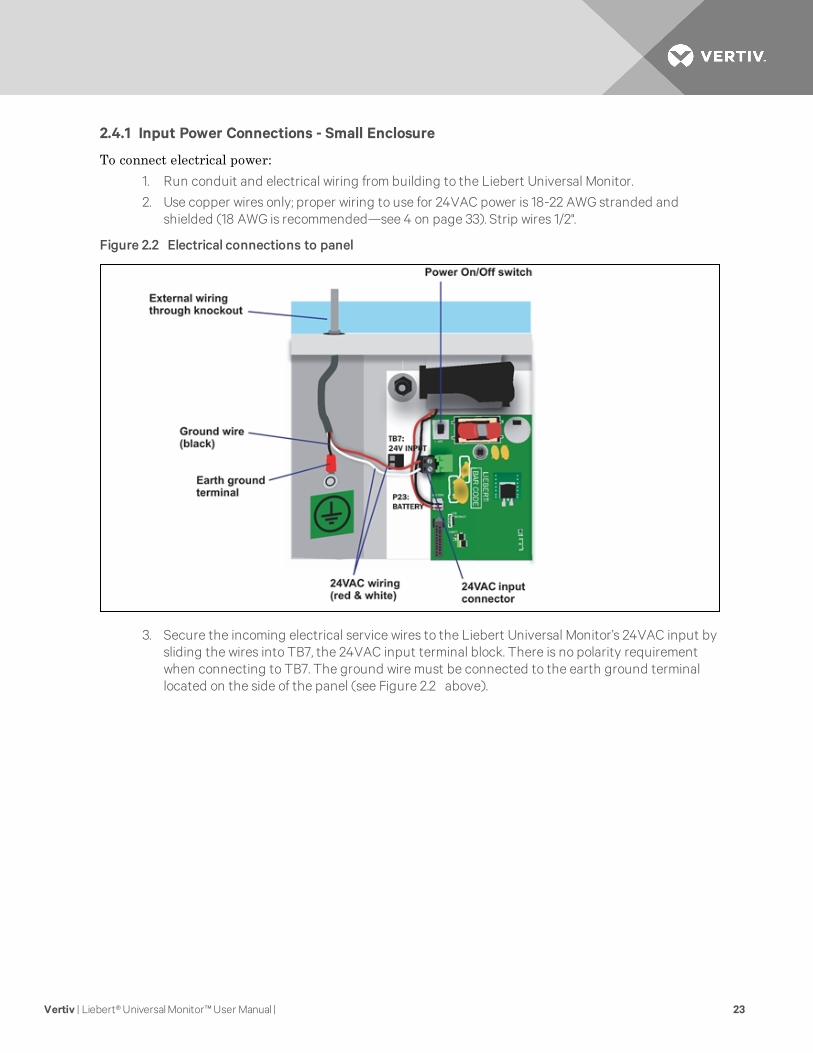
2.4.1 Input Power Connections - Small Enclosure
To connect electrical power:1. Run conduit and electrical wiring from building to the Liebert Universal Monitor.
2. Use copper wires only; proper wiring to use for 24VAC power is 18-22 AWG stranded andshielded (18 AWG is recommended—see 4 on page 33). Strip wires 1/2".
Figure 2.2 Electrical connections to panel
3. Secure the incoming electrical service wires to the Liebert Universal Monitor’s 24VAC input bysliding the wires into TB7, the 24VAC input terminal block. There is no polarity requirementwhen connecting to TB7. The ground wire must be connected to the earth ground terminallocated on the side of the panel (see Figure 2.2 above).
Vertiv | Liebert® Universal Monitor™ User Manual | 23
2.4.2 Termination and Mounting - Large Enclosure
CAUTION: The 115VAC/230VAC Transformer Module must be connected to a branch circuitwith 15A branch circuit protection. This equipment is intended to be installed by a qualified andcertified electrician who must review and approve customer supplied wiring and circuitbreakers, verify correct input and grounded connections to ensure compliance with thetechnical standards and national and local electrical codes.
The Transformer Module shall be used only as indicated by the manufacturer.
WARNING! Be sure that the Power On/Off switch is set to OFF before installing anywiring tothis unit. The switch is at the bottom of the unit.
Input Power Connections
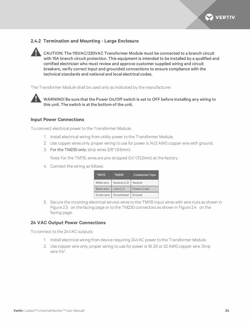
To connect electrical power to the Transformer Module:
1. Install electrical wiring from utility power to the Transformer Module.
2. Use copper wires only; proper wiring to use for power is 14/2 AWG copper wire with ground.
3. For the TM230 only: strip wires 3/8" (9.6mm).
Note: For the TM115, wires are pre-stripped 0.4" (10.2mm) at the factory.
4. Connect the wiring as follows:
TM115 TM230 ConnectionType
White wire Neutral (L2) Neutral
Black wire Line (L1) Power (Line)
Green wire Ground lead Ground
5. Secure the incoming electrical service wires to the TM115 input wires with wire nuts as shown inFigure 2.3 on the facing page or to the TM230 connectors as shown in Figure 2.4 on thefacing page.
24 VAC Output Power Connections
To connect to the 24VAC outputs:
1. Install electrical wiring from device requiring 24VAC power to the Transformer Module.
2. Use copper wire only; proper wiring to use for power is 18, 20 or 22 AWG copper wire. Stripwire 1/4".
Vertiv | Liebert® Universal Monitor™ User Manual | 24
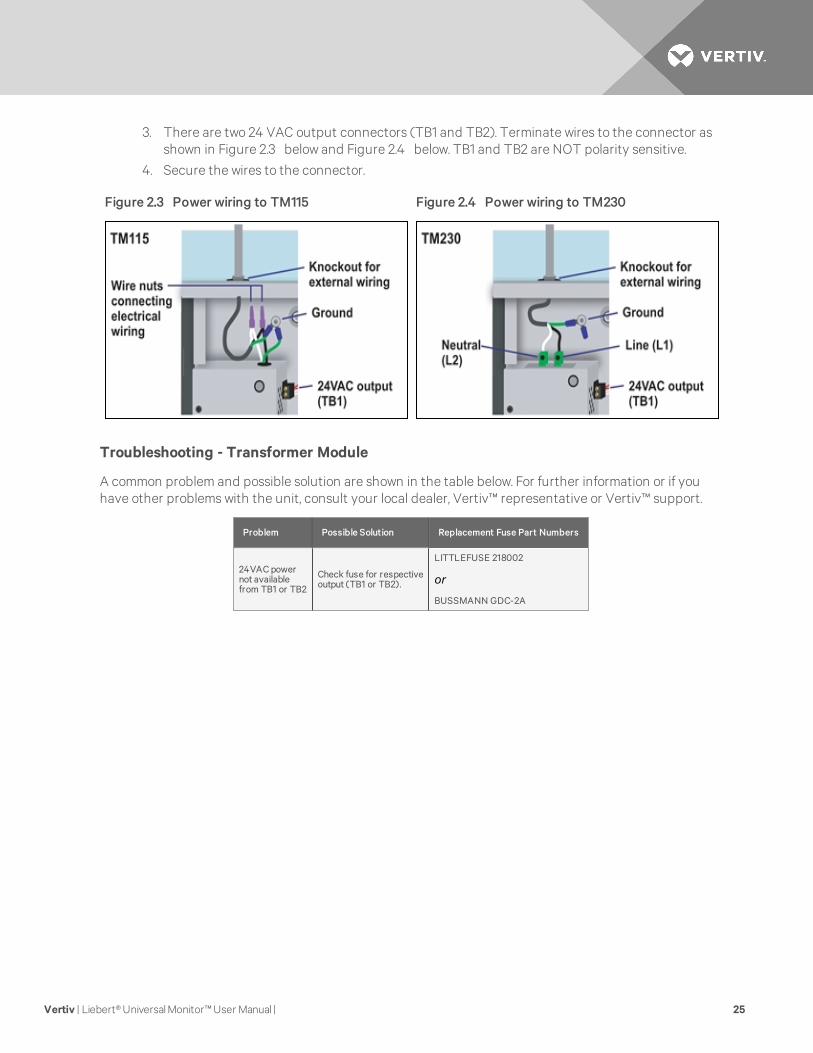
3. There are two 24 VAC output connectors (TB1 and TB2). Terminate wires to the connector asshown in Figure 2.3 below and Figure 2.4 below. TB1 and TB2 are NOT polarity sensitive.
4. Secure the wires to the connector.
Figure 2.3 Power wiring to TM115 Figure 2.4 Power wiring to TM230
Troubleshooting - Transformer Module
A common problem and possible solution are shown in the table below. For further information or if youhave other problems with the unit, consult your local dealer, Vertiv™ representative or Vertiv™ support.
Problem Possible Solution Replacement Fuse Part Numbers
24VAC powernot availablefrom TB1 or TB2
Check fuse for respectiveoutput (TB1 or TB2).
LITTLEFUSE 218002
or
BUSSMANN GDC-2A
Vertiv | Liebert® Universal Monitor™ User Manual | 25
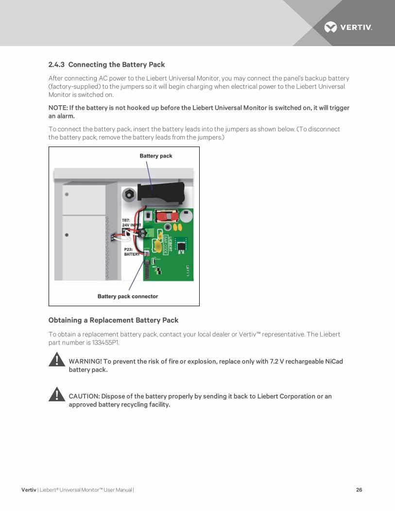
2.4.3 Connecting the Battery Pack
After connecting AC power to the Liebert Universal Monitor, you may connect the panel’s backup battery(factory-supplied) to the jumpers so it will begin charging when electrical power to the Liebert UniversalMonitor is switched on.
NOTE: If the battery is not hooked up before the Liebert Universal Monitor is switched on, it will triggeran alarm.
To connect the battery pack, insert the battery leads into the jumpers as shown below. (To disconnectthe battery pack, remove the battery leads from the jumpers.)
Obtaining a Replacement Battery Pack
To obtain a replacement battery pack, contact your local dealer or Vertiv™ representative. The Liebertpart number is 133455P1.
WARNING! To prevent the risk of fire or explosion, replace only with 7.2 V rechargeable NiCadbattery pack.
CAUTION: Dispose of the battery properly by sending it back to Liebert Corporation or anapproved battery recycling facility.
Vertiv | Liebert® Universal Monitor™ User Manual | 26

3 INSTALLATION - OPTIONAL EXPANSION BOARDThis section provides instructions for installing, mounting and connecting power to the optionalExpansion Board. The Expansion Board enclosure is identical to the Liebert Universal Monitor smallenclosure.
3.1 Installation Considerations
The optional Expansion Board must be installed indoors and may be mounted on the surface of a wall orflush-mounted, depending on the user’s application, the location of equipment and sensors to bemonitored and the type of wall the unit will be mounted on.
The Expansion Board may be placed up to 3000 ft. (914m) from the Liebert Universal Monitor and shouldbe mounted where it can be easily accessed. The site must have electrical service and allow forconnecting 16 digital inputs and eight digital outputs.
The wall material must be capable of supporting the weight of the Expansion Board: see OptionalExpansion Board Specifications on page 106.
NOTE: This equipment has been tested and found to comply with the limits for a Class A digital device,pursuant to part 15 of the FCC rules. These limits are designed to provide reasonable protectionagainst harmful interference when the equipment is operated in a commercial environment. Thisequipment generates, uses, and can radiate radio frequency energy and, if not installed and used inaccordance with the instruction manual, may cause harmful interference to radio communications.Operation of this equipment in a residential area is likely to cause harmful interference in which casethe user will be required to correct the interference at his own expense.
3.1.1 Unpacking and Preliminary Inspection
• Before unpacking the optional Expansion Board, inspect the shipping carton for damage orsigns of mishandling, such as gashes or holes in the carton or severely flattened corners.
• Open the shipping crates carefully. Use care to avoid puncturing the container with sharpobjects that might damage the contents.
• Inspect the Expansion Board and all included components for damage.
• If any damage from shipping or mishandling is observed, immediately file a damage claim withthe shipping agency and forward a copy to:
Vertiv Corporation1050 Dearborn DriveP.O. Box 29186Columbus, OH 43229
Vertiv | Liebert® Universal Monitor™ User Manual | 27
Packing Contents
Standard Components
Expansion Board - small enclosure
User Manual
Keys (2) to panel door lock
Two (2) spare fuses for output relays
Table 3.1 Packingmanifest - optionalExpansion Board
3.2 Surface-Mounting the Optional Expansion Board
NOTE: Removing the conduit knockouts before mounting the optional Expansion Board on the wallwill ease installation and prevent strain on the mounting hardware and wall. It is imperative to removethe knockouts if the unit is to be flush-mounted.
After determining where to place the optional Expansion Board, check to ensure that you have all thehardware required to install the panel on the surface of a wall. Obtain the needed tools and material.
Required tools
• Electric drill (if surface is too hard to drive screws without pilot holes)
• Screwdriver
• Marker to denote layout of holes
• Four screws, each #10
3.2.1 Mounting the Panel
CAUTION: Check building plans and other relevant documents to determine whether mountingthe optional Expansion Board at the selected location might cause cutting or otherwisedamaging electrical or communication wiring or pipes.
1. Mark the wall for mounting holes, using the back of the unit as a template (see Figure 3.1 onthe facing page).
2. Drill holes, if required, to install the four #10 screws that will secure the optional ExpansionBoard to the wall. Clean up the debris.
3. If the wall material is not strong enough to hold the screws securely, use wall anchors.
4. Install the top two screws—the screw heads must be small enough to slip through the larger,bottom portion of the pear-shaped mounting slot in the Expansion Board (see inset in Figure3.1 on the facing page). The screws must also be large enough to extend over the edges of thetop of the mounting slot.
5. Hang the Expansion Board on the screws, letting the panel slip down until the screws are in thesmaller, upper portion of the slot.
6. Tighten the screws until they are snug.
7. Insert the remaining two screws in the bottom holes on the back of the panel and tighten.
Vertiv | Liebert® Universal Monitor™ User Manual | 28
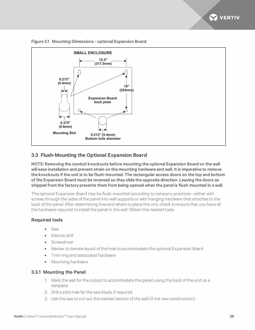
Figure 3.1 Mounting Dimensions - optional Expansion Board
3.3 Flush-Mounting the Optional Expansion Board
NOTE: Removing the conduit knockouts before mounting the optional Expansion Board on the wallwill ease installation and prevent strain on the mounting hardware and wall. It is imperative to removethe knockouts if the unit is to be flush-mounted. The rectangular access doors on the top and bottomof the Expansion Board must be reversed so they slide the opposite direction. Leaving the doors asshipped from the factory prevents them from being opened when the panel is flush mounted in a wall.
The optional Expansion Board may be flush-mounted according to company practices—either withscrews through the sides of the panel into wall supports or with hanging hardware that attaches to theback of the panel. After determining how and where to place the unit, check to ensure that you have allthe hardware required to install the panel in the wall. Obtain the needed tools.
Required tools
• Saw
• Electric drill
• Screwdriver
• Marker to denote layout of the hole to accommodate the optional Expansion Board
• Trim ring and associated hardware
• Mounting hardware
3.3.1 Mounting the Panel
1. Mark the wall for the cutout to accommodate the panel, using the back of the unit as atemplate.
2. Drill a pilot hole for the saw blade, if required.
3. Use the saw to cut out the marked section of the wall (if not new construction).
Vertiv | Liebert® Universal Monitor™ User Manual | 29
4. Rest the optional Expansion Board in the wall and mark where mounting screws will be insertedinto the wall studs or other support member.
5. Remove the panel and drill the holes for the mounting screws or wall anchors. Clean up thedebris.
6. Reverse the slide direction of the rectangular access doors on the top and bottom of theExpansion Board. Leaving the doors as shipped from the factory prevents them from beingopened when the panel is flush mounted in a wall.
7. Attach any field-supplied mounting hardware.
8. Reinsert the assembly into the wall.
9. Insert and tighten the screws or wall anchors.
CAUTION: Check building plans and other relevant documents to determine whether mountingthe optional Expansion Board at the selected location might cause cutting or otherwisedamaging electrical or communication wiring or pipes.
3.4 Input Power Connections - Optional Expansion Board
The optional Expansion Board requires 24VAC for proper operation. Vertiv™ recommends using theoptional Transformer Module manufactured by Liebert or another UL-approved Class 2 power unit toobtain proper voltage. If the power unit is not a Class 2 circuit, it must be protected with an IEC 5 x 20mmtime lag 2A fuse. For information, consult your local dealer, Vertiv™ representative Vertiv™ Support.
CAUTION: The Expansion Board is designed for use on properly grounded (earthed) 24VACClass 2 power, 50Hz or 60Hz. The ground wire for the power lead must be wired to the earthground terminal (stud located next to the 24VAC terminal block). This equipment is intended tobe installed by a qualified and certified electrician who must review and approve customer-supplied wiring and circuit breakers, verify correct input and grounded (earthed) connectionsto ensure compliance with technical standards and national and local electrical codes.
WARNING! “RISK OF ELECTRIC SHOCK” - More than one disconnect switch may be requiredto de-energize the equipment before servicing.
WARNING! Hazardous voltage may be present.
To connect electrical power:
1. Run 24VAC electrical power from the TB2 (or TB1) connector of the Transformer Module, asshown in Figure 3.2 on the facing page, or another 24V source to the Expansion Board inaccordance with local electrical codes.
2. Use copper wires only; proper wiring to use for power is 18-22 AWG stranded and shielded(18 AWG is recommended—see Table 5.1 on page 43). Strip wires 1/2".
Vertiv | Liebert® Universal Monitor™ User Manual | 30
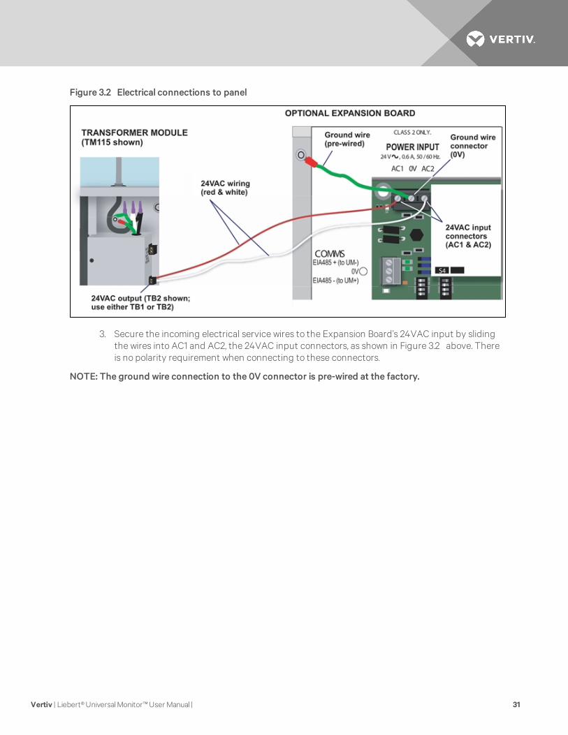
Figure 3.2 Electrical connections to panel
3. Secure the incoming electrical service wires to the Expansion Board’s 24VAC input by slidingthe wires into AC1 and AC2, the 24VAC input connectors, as shown in Figure 3.2 above. Thereis no polarity requirement when connecting to these connectors.
NOTE: The ground wire connection to the 0V connector is pre-wired at the factory.
Vertiv | Liebert® Universal Monitor™ User Manual | 31

Vertiv | Liebert® Universal Monitor™ User Manual | 32
This page intentionally left blank.
4 WIRING AND CONNECTIONS - MAIN BOARD
CAUTION: Switch OFF electric power to the Liebert Universal Monitor before installing anywiring to the unit or changing input or output connections. The Power On/Off switch is in thetop left corner of the unit, just below the battery pack.
4.1 Wiring Specifications
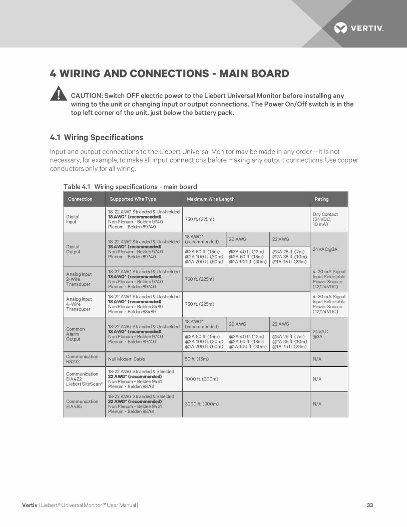
Input and output connections to the Liebert Universal Monitor may be made in any order—it is notnecessary, for example, to make all input connections before making any output connections. Use copperconductors only for all wiring.
Connection Supported Wire Type Maximum Wire Length Rating
DigitalInput
18-22 AWG Stranded & Unshielded18AWG* (recommended)Non Plenum - Belden 9740Plenum - Belden 89740
750 ft. (225m)Dry Contact(24VDC,10 mA)
DigitalOutput
18-22 AWG Stranded & Unshielded18AWG* (recommended)Non Plenum - Belden 9740Plenum - Belden 89740
18 AWG*(recommended) 20 AWG 22 AWG
24VAC@3A@3A 50 ft. (15m)@2A 100 ft. (30m)@1A 200 ft. (60m)
@3A 40 ft. (12m)@2A 60 ft. (18m)@1A 100 ft. (30m)
@3A 25 ft. (7m)@2A 35 ft. (10m)@1A 75 ft. (23m)
Analog Input2-WireTransducer
18-22 AWG Stranded & Unshielded18AWG* (recommended)Non Plenum - Belden 9740Plenum - Belden 89740
750 ft. (225m)
4-20 mA SignalInput SelectablePower Source(12/24VDC)
Analog Input4-WireTransducer
18-22 AWG Stranded & Unshielded18AWG* (recommended)Non Plenum - Belden 8489Plenum - Belden 88489
750 ft. (225m)
4-20 mA SignalInput SelectablePower Source(12/24VDC)
CommonAlarmOutput
18-22 AWG Stranded & Unshielded18AWG* (recommended)Non Plenum - Belden 9740Plenum - Belden 89740
18 AWG*(recommended) 20 AWG 22 AWG
24VAC@3A@3A 50 ft. (15m)
@2A 100 ft. (30m)@1A 200 ft. (60m)
@3A 40 ft. (12m)@2A 60 ft. (18m)@1A 100 ft. (30m)
@3A 25 ft. (7m)@2A 35 ft. (10m)@1A 75 ft. (23m)
CommunicationRS232 Null Modem Cable 50 ft. (15m) N/A
CommunicationEIA422Liebert SiteScan®
18-22 AWG Stranded & Shielded22AWG* (recommended)Non Plenum - Belden 9461Plenum - Belden 88761
1000 ft. (300m) N/A
CommunicationEIA485
18-22 AWG Stranded & Shielded22AWG* (recommended)Non Plenum - Belden 9461Plenum - Belden 88761
3000 ft. (900m) N/A
Table 4.1 Wiring specifications - main board
Vertiv | Liebert® Universal Monitor™ User Manual | 33
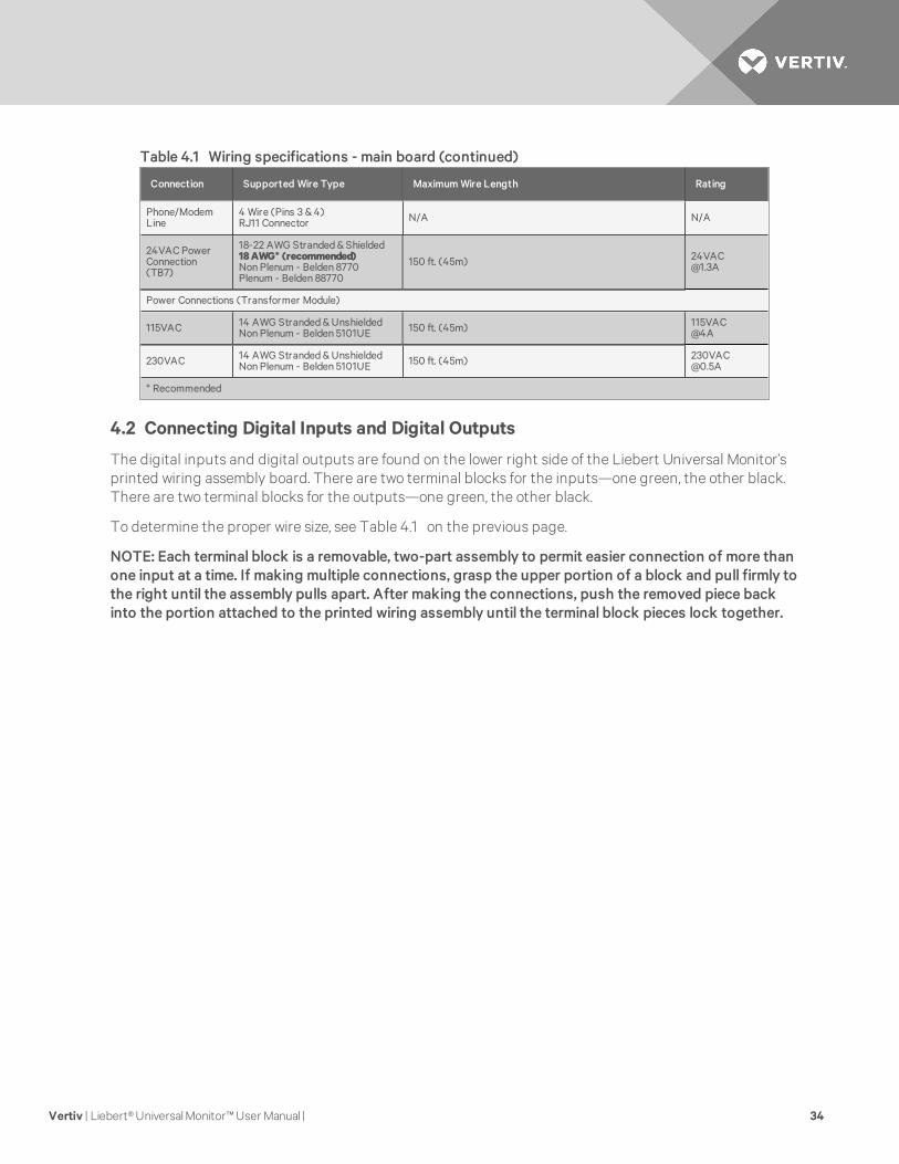
Connection Supported Wire Type Maximum Wire Length Rating
Phone/ModemLine
4 Wire (Pins 3 & 4)RJ11 Connector N/A N/A
24VAC PowerConnection(TB7)
18-22 AWG Stranded & Shielded18AWG* (recommended)Non Plenum - Belden 8770Plenum - Belden 88770
150 ft. (45m) [email protected]
Power Connections (Transformer Module)
115VAC 14 AWG Stranded & UnshieldedNon Plenum - Belden 5101UE 150 ft. (45m) 115VAC
@4A
230VAC 14 AWG Stranded & UnshieldedNon Plenum - Belden 5101UE 150 ft. (45m) 230VAC
@0.5A
* Recommended
Table 4.1 Wiring specifications - main board (continued)
4.2 Connecting Digital Inputs and Digital Outputs
The digital inputs and digital outputs are found on the lower right side of the Liebert Universal Monitor’sprinted wiring assembly board. There are two terminal blocks for the inputs—one green, the other black.There are two terminal blocks for the outputs—one green, the other black.
To determine the proper wire size, see Table 4.1 on the previous page.
NOTE: Each terminal block is a removable, two-part assembly to permit easier connection of more thanone input at a time. If making multiple connections, grasp the upper portion of a block and pull firmly tothe right until the assembly pulls apart. After making the connections, push the removed piece backinto the portion attached to the printed wiring assembly until the terminal block pieces lock together.
Vertiv | Liebert® Universal Monitor™ User Manual | 34
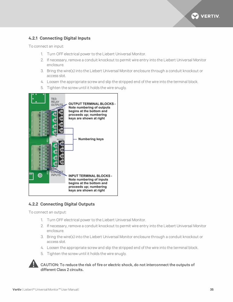
4.2.1 Connecting Digital Inputs
To connect an input:
1. Turn OFF electrical power to the Liebert Universal Monitor.
2. If necessary, remove a conduit knockout to permit wire entry into the Liebert Universal Monitorenclosure.
3. Bring the wire(s) into the Liebert Universal Monitor enclosure through a conduit knockout oraccess slot.
4. Loosen the appropriate screw and slip the stripped end of the wire into the terminal block.
5. Tighten the screw until it holds the wire snugly.
4.2.2 Connecting Digital Outputs
To connect an output:
1. Turn OFF electrical power to the Liebert Universal Monitor.
2. If necessary, remove a conduit knockout to permit wire entry into the Liebert Universal Monitorenclosure.
3. Bring the wire(s) into the Liebert Universal Monitor enclosure through a conduit knockout oraccess slot.
4. Loosen the appropriate screw and slip the stripped end of the wire into the terminal block.
5. Tighten the screw until it holds the wire snugly.
CAUTION: To reduce the risk of fire or electric shock, do not interconnect the outputs ofdifferent Class 2 circuits.
Vertiv | Liebert® Universal Monitor™ User Manual | 35
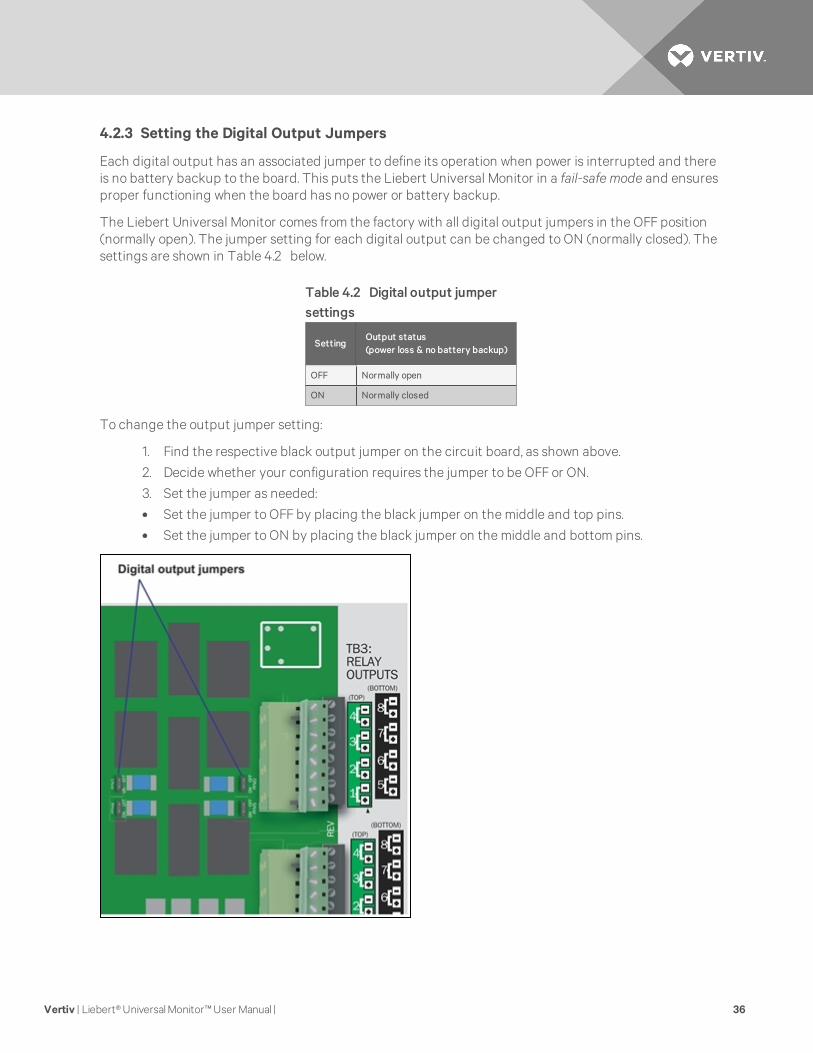
4.2.3 Setting the Digital Output Jumpers
Each digital output has an associated jumper to define its operation when power is interrupted and thereis no battery backup to the board. This puts the Liebert Universal Monitor in a fail-safe mode and ensuresproper functioning when the board has no power or battery backup.
The Liebert Universal Monitor comes from the factory with all digital output jumpers in the OFF position(normally open). The jumper setting for each digital output can be changed to ON (normally closed). Thesettings are shown in Table 4.2 below.
SettingOutput status(power loss & no battery backup)
OFF Normally open
ON Normally closed
Table 4.2 Digital output jumpersettings
To change the output jumper setting:
1. Find the respective black output jumper on the circuit board, as shown above.
2. Decide whether your configuration requires the jumper to be OFF or ON.
3. Set the jumper as needed:
• Set the jumper to OFF by placing the black jumper on the middle and top pins.
• Set the jumper to ON by placing the black jumper on the middle and bottom pins.
Vertiv | Liebert® Universal Monitor™ User Manual | 36
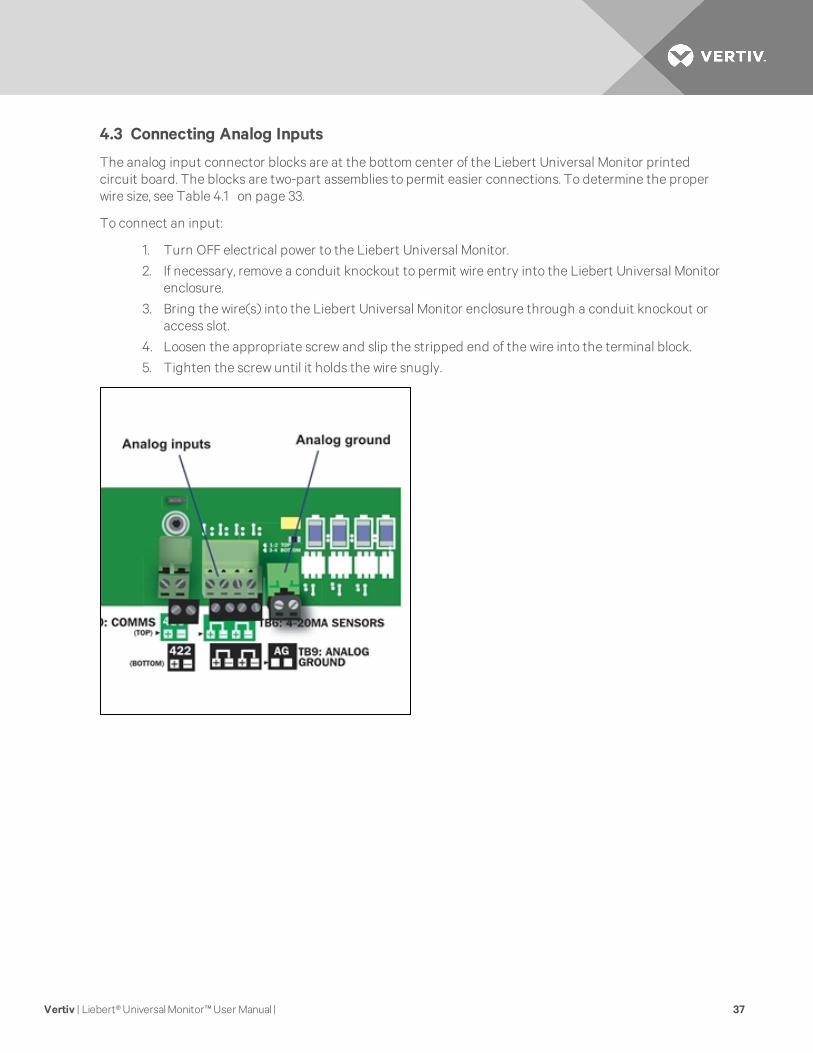
4.3 Connecting Analog Inputs
The analog input connector blocks are at the bottom center of the Liebert Universal Monitor printedcircuit board. The blocks are two-part assemblies to permit easier connections. To determine the properwire size, see Table 4.1 on page 33.
To connect an input:
1. Turn OFF electrical power to the Liebert Universal Monitor.
2. If necessary, remove a conduit knockout to permit wire entry into the Liebert Universal Monitorenclosure.
3. Bring the wire(s) into the Liebert Universal Monitor enclosure through a conduit knockout oraccess slot.
4. Loosen the appropriate screw and slip the stripped end of the wire into the terminal block.
5. Tighten the screw until it holds the wire snugly.
Vertiv | Liebert® Universal Monitor™ User Manual | 37
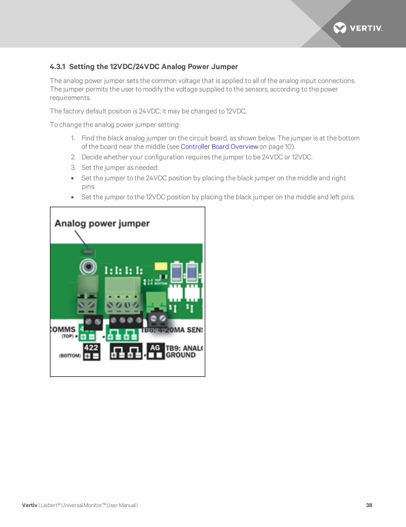
4.3.1 Setting the 12VDC/24VDC Analog Power Jumper
The analog power jumper sets the common voltage that is applied to all of the analog input connections.The jumper permits the user to modify the voltage supplied to the sensors, according to the powerrequirements.
The factory default position is 24VDC; it may be changed to 12VDC.
To change the analog power jumper setting:
1. Find the black analog jumper on the circuit board, as shown below. The jumper is at the bottomof the board near the middle (see Controller Board Overview on page 10).
2. Decide whether your configuration requires the jumper to be 24VDC or 12VDC.
3. Set the jumper as needed:
• Set the jumper to the 24VDC position by placing the black jumper on the middle and rightpins.
• Set the jumper to the 12VDC position by placing the black jumper on the middle and left pins.
Vertiv | Liebert® Universal Monitor™ User Manual | 38
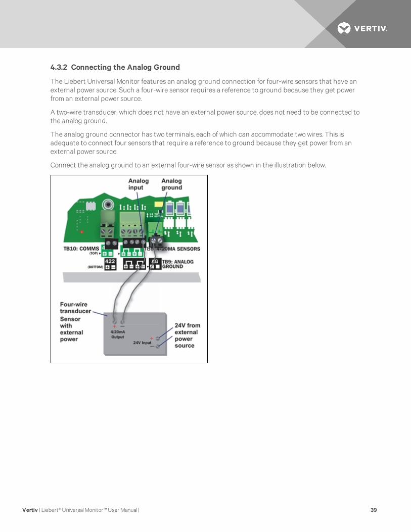
4.3.2 Connecting the Analog Ground
The Liebert Universal Monitor features an analog ground connection for four-wire sensors that have anexternal power source. Such a four-wire sensor requires a reference to ground because they get powerfrom an external power source.
A two-wire transducer, which does not have an external power source, does not need to be connected tothe analog ground.
The analog ground connector has two terminals, each of which can accommodate two wires. This isadequate to connect four sensors that require a reference to ground because they get power from anexternal power source.
Connect the analog ground to an external four-wire sensor as shown in the illustration below.
Vertiv | Liebert® Universal Monitor™ User Manual | 39
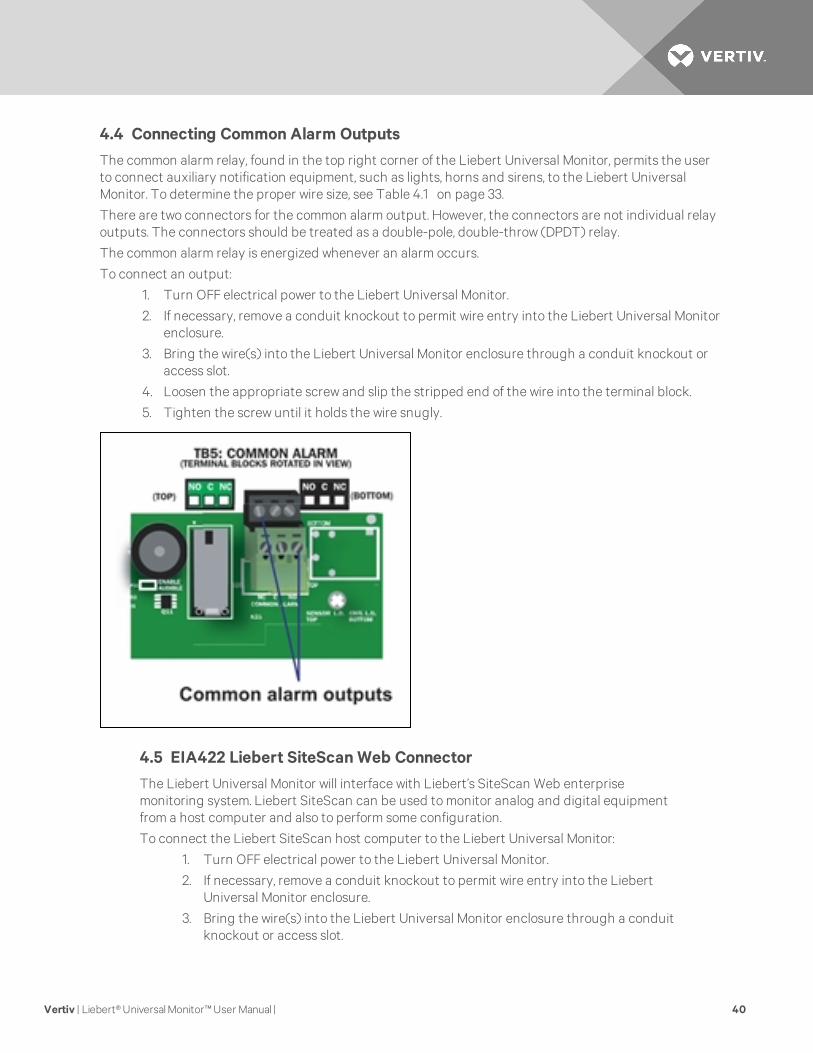
4.4 Connecting Common Alarm Outputs
The common alarm relay, found in the top right corner of the Liebert Universal Monitor, permits the userto connect auxiliary notification equipment, such as lights, horns and sirens, to the Liebert UniversalMonitor. To determine the proper wire size, see Table 4.1 on page 33.
There are two connectors for the common alarm output. However, the connectors are not individual relayoutputs. The connectors should be treated as a double-pole, double-throw (DPDT) relay.
The common alarm relay is energized whenever an alarm occurs.
To connect an output:
1. Turn OFF electrical power to the Liebert Universal Monitor.
2. If necessary, remove a conduit knockout to permit wire entry into the Liebert Universal Monitorenclosure.
3. Bring the wire(s) into the Liebert Universal Monitor enclosure through a conduit knockout oraccess slot.
4. Loosen the appropriate screw and slip the stripped end of the wire into the terminal block.
5. Tighten the screw until it holds the wire snugly.
4.5 EIA422 Liebert SiteScan Web Connector
The Liebert Universal Monitor will interface with Liebert’s SiteScan Web enterprisemonitoring system. Liebert SiteScan can be used to monitor analog and digital equipmentfrom a host computer and also to perform some configuration.
To connect the Liebert SiteScan host computer to the Liebert Universal Monitor:
1. Turn OFF electrical power to the Liebert Universal Monitor.
2. If necessary, remove a conduit knockout to permit wire entry into the LiebertUniversal Monitor enclosure.
3. Bring the wire(s) into the Liebert Universal Monitor enclosure through a conduitknockout or access slot.
Vertiv | Liebert® Universal Monitor™ User Manual | 40
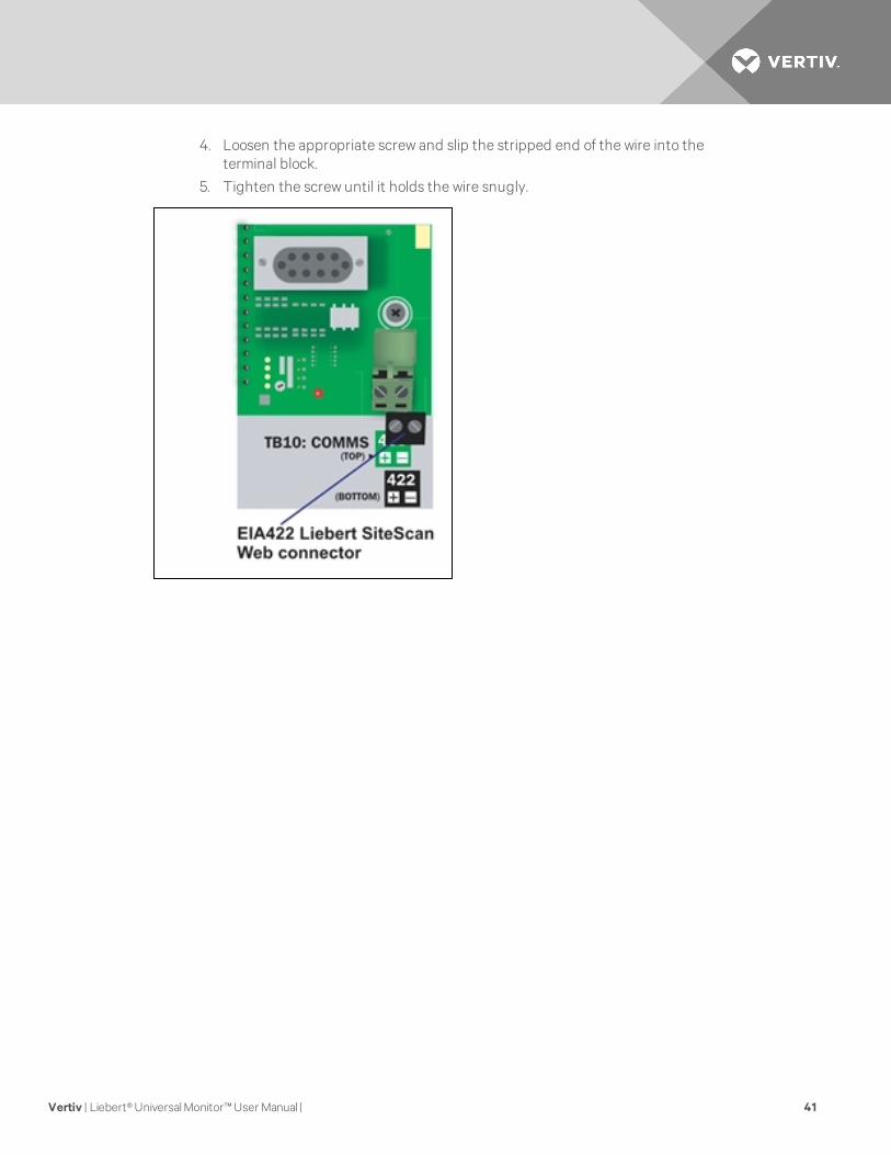
4. Loosen the appropriate screw and slip the stripped end of the wire into theterminal block.
5. Tighten the screw until it holds the wire snugly.
Vertiv | Liebert® Universal Monitor™ User Manual | 41
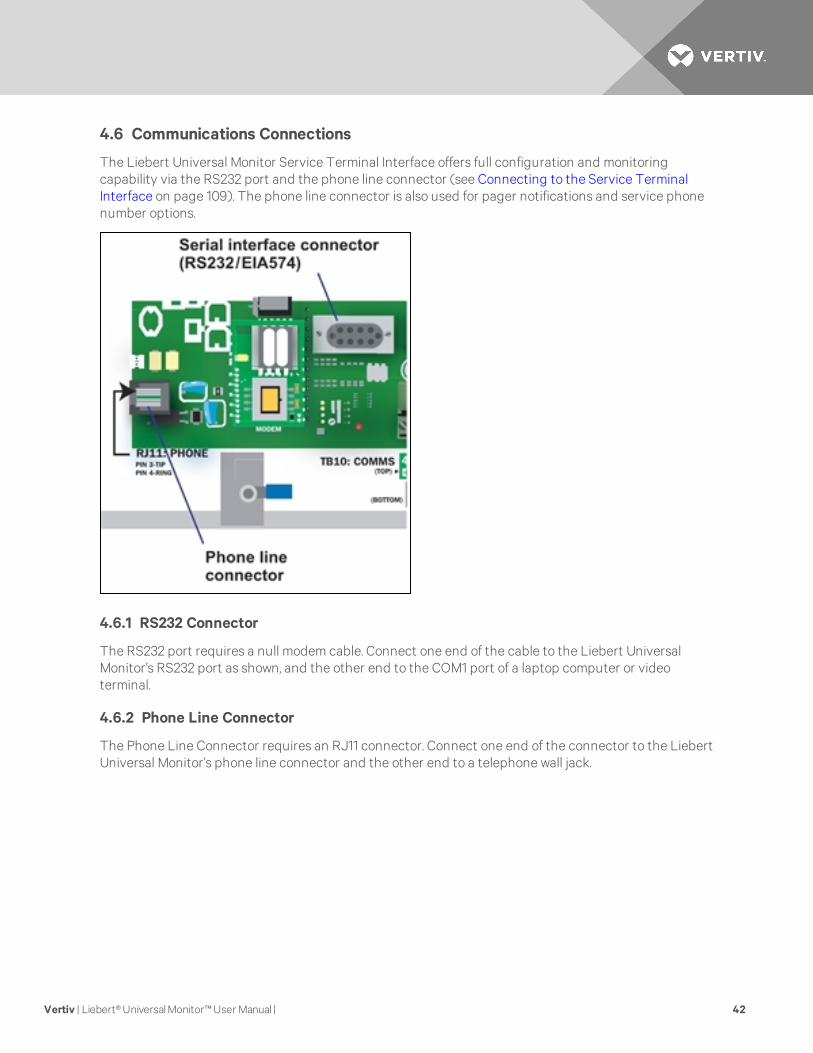
4.6 Communications Connections
The Liebert Universal Monitor Service Terminal Interface offers full configuration and monitoringcapability via the RS232 port and the phone line connector (see Connecting to the Service TerminalInterface on page 109). The phone line connector is also used for pager notifications and service phonenumber options.
4.6.1 RS232 Connector
The RS232 port requires a null modem cable. Connect one end of the cable to the Liebert UniversalMonitor’s RS232 port as shown, and the other end to the COM1 port of a laptop computer or videoterminal.
4.6.2 Phone Line Connector
The Phone Line Connector requires an RJ11 connector. Connect one end of the connector to the LiebertUniversal Monitor’s phone line connector and the other end to a telephone wall jack.
Vertiv | Liebert® Universal Monitor™ User Manual | 42
5 WIRING AND CONNECTIONS - OPTIONAL EXPANSIONBOARD
CAUTION: Remove all power before installing anywiring to the Expansion Board or changinginput or output connections.
WARNING! “RISK OF ELECTRIC SHOCK” - More than one disconnect switch may be requiredto de-energize the equipment before servicing.
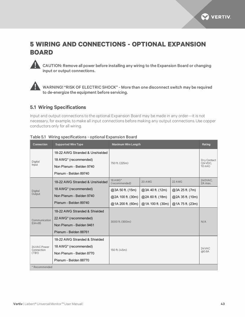
5.1 Wiring Specifications
Input and output connections to the optional Expansion Board may be made in any order—it is notnecessary, for example, to make all input connections before making any output connections. Use copperconductors only for all wiring.
Connection Supported Wire Type Maximum Wire Length Rating
DigitalInput
18-22 AWG Stranded & Unshielded
18 AWG* (recommended)
Non Plenum - Belden 9740
Plenum - Belden 89740
750 ft. (225m)Dry Contact(24VDC,10 mA)
DigitalOutput
18-22 AWG Stranded & Unshielded
18 AWG* (recommended)
Non Plenum - Belden 9740
Plenum - Belden 89740
18 AWG*(recommended) 20 AWG 22 AWG 240VAC,
2A max.
@3A 50 ft. (15m)
@2A 100 ft. (30m)
@1A 200 ft. (60m)
@3A 40 ft. (12m)
@2A 60 ft. (18m)
@1A 100 ft. (30m)
@3A 25 ft. (7m)
@2A 35 ft. (10m)
@1A 75 ft. (23m)
CommunicationEIA485
18-22 AWG Stranded & Shielded
22 AWG* (recommended)
Non Plenum - Belden 9461
Plenum - Belden 88761
3000 ft. (900m) N/A
24VAC PowerConnection(TB1)
18-22 AWG Stranded & Shielded
18 AWG* (recommended)
Non Plenum - Belden 8770
Plenum - Belden 88770
150 ft. (45m) [email protected]
* Recommended
Table 5.1 Wiring specifications - optional Expansion Board
Vertiv | Liebert® Universal Monitor™ User Manual | 43
5.2 Connecting Inputs and Outputs
The Liebert Universal Monitor optional Expansion Board permits the addition of 16 input and eight outputdevices. This section describes how to connect devices to the Expansion Board’s inputs and outputs.
To determine the proper wire size, see Table 5.1 on the previous page.
NOTE: Each terminal block is a removable assembly to permit easier connection of more than one inputat a time. If making multiple connections, grasp the upper portion of a block and pull firmly until theassembly pulls apart. After making the connections, push the removed piece back into the portionattached to the printed wiring assembly until the terminal block pieces lock together.
5.2.1 Connecting Digital Inputs
The 16 digital inputs are found on the lower portion of the Expansion Board, as shown below. These inputsare numbered 9 through 24 (the Liebert Universal Monitor’s digital inputs are numbered 1 through 8).
To connect an input:
1. Disconnect all electrical power from the Expansion Board.
2. If necessary, remove a conduit knockout to permit wire entry into the Expansion Boardenclosure.
3. Bring the wire(s) into the Expansion Board enclosure through a conduit knockout or accessslot.
4. Loosen the appropriate screw and slip the stripped end of the wire into the terminal block.
5. Tighten the screw until it holds the wire snugly.
Vertiv | Liebert® Universal Monitor™ User Manual | 44

5.2.2 Connecting Digital Outputs
The eight digital outputs are found at the top of the Expansion Board, as shown below. These inputs arenumbered 9 through 16. (Note that the digital outputs on the main board of the Liebert Universal Monitorare numbered 1 - 8.)
WARNING! “RISK OF ELECTRIC SHOCK” - Hazardous voltage may be present. More than onedisconnect switch may be required to de-energize the equipment before servicing.
CAUTION: The Expansion Board is designed for use on properly grounded (earthed) 24VACClass 2 power, 50Hz or 60Hz. The ground wire for the power lead must be wired to the earthground terminal (stud located next to the 24VAC terminal block). This equipment is intended tobe installed by a qualified and certified electrician who must review and approve customer-supplied wiring and circuit breakers, verify correct input and grounded (earthed) connectionsto ensure compliance with technical standards and national and local electrical codes.Segregate and install separate electrical conduits for non-class 2 circuits in accordance withlocal building codes.
Vertiv | Liebert® Universal Monitor™ User Manual | 45
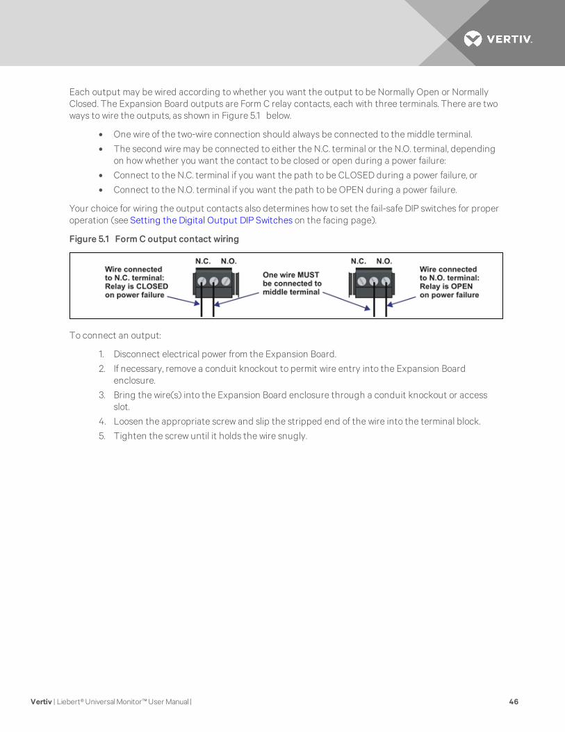
Each output may be wired according to whether you want the output to be Normally Open or NormallyClosed. The Expansion Board outputs are Form C relay contacts, each with three terminals. There are twoways to wire the outputs, as shown in Figure 5.1 below.
• One wire of the two-wire connection should always be connected to the middle terminal.
• The second wire may be connected to either the N.C. terminal or the N.O. terminal, dependingon how whether you want the contact to be closed or open during a power failure:
• Connect to the N.C. terminal if you want the path to be CLOSED during a power failure, or
• Connect to the N.O. terminal if you want the path to be OPEN during a power failure.
Your choice for wiring the output contacts also determines how to set the fail-safe DIP switches for properoperation (see Setting the Digital Output DIP Switches on the facing page).
Figure 5.1 Form C output contact wiring
To connect an output:
1. Disconnect electrical power from the Expansion Board.
2. If necessary, remove a conduit knockout to permit wire entry into the Expansion Boardenclosure.
3. Bring the wire(s) into the Expansion Board enclosure through a conduit knockout or accessslot.
4. Loosen the appropriate screw and slip the stripped end of the wire into the terminal block.
5. Tighten the screw until it holds the wire snugly.
Vertiv | Liebert® Universal Monitor™ User Manual | 46
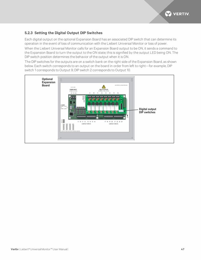
5.2.3 Setting the Digital Output DIP Switches
Each digital output on the optional Expansion Board has an associated DIP switch that can determine itsoperation in the event of loss of communication with the Liebert Universal Monitor or loss of power.When the Liebert Universal Monitor calls for an Expansion Board output to be ON, it sends a command tothe Expansion Board to turn the output to the ON state; this is signified by the output LED being ON. TheDIP switch position determines the behavior of the output when it is ON.The DIP switches for the outputs are on a switch bank on the right side of the Expansion Board, as shownbelow. Each switch corresponds to an output on the board in order from left to right—for example, DIPswitch 1 corresponds to Output 9; DIP switch 2 corresponds to Output 10.
Vertiv | Liebert® Universal Monitor™ User Manual | 47
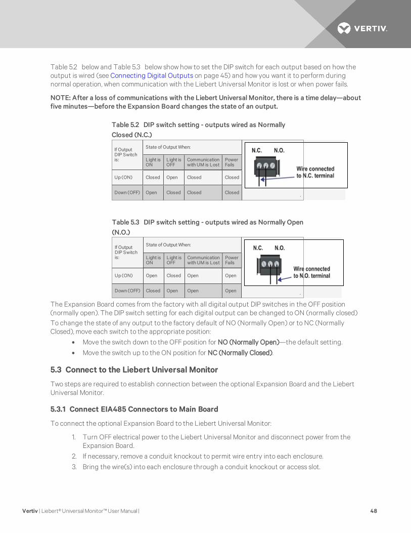
Table 5.2 below and Table 5.3 below show how to set the DIP switch for each output based on how theoutput is wired (see Connecting Digital Outputs on page 45) and how you want it to perform duringnormal operation, when communication with the Liebert Universal Monitor is lost or when power fails.
NOTE: After a loss of communications with the Liebert Universal Monitor, there is a time delay—aboutfive minutes—before the Expansion Board changes the state of an output.
If OutputDIP Switchis:
State of Output When:
.
Light isON
Light isOFF
Communicationwith UM is Lost
PowerFails
Up (ON) Closed Open Closed Closed
Down (OFF) Open Closed Closed Closed
Table 5.2 DIP switch setting - outputs wired as NormallyClosed (N.C.)
If OutputDIP Switchis:
State of Output When:
.
Light isON
Light isOFF
Communicationwith UM is Lost
PowerFails
Up (ON) Open Closed Open Open
Down (OFF) Closed Open Open Open
Table 5.3 DIP switch setting - outputs wired as Normally Open(N.O.)
The Expansion Board comes from the factory with all digital output DIP switches in the OFF position(normally open). The DIP switch setting for each digital output can be changed to ON (normally closed)To change the state of any output to the factory default of NO (Normally Open) or to NC (NormallyClosed), move each switch to the appropriate position:
• Move the switch down to the OFF position for NO (Normally Open)—the default setting.
• Move the switch up to the ON position for NC (Normally Closed).
5.3 Connect to the Liebert Universal Monitor
Two steps are required to establish connection between the optional Expansion Board and the LiebertUniversal Monitor.
5.3.1 Connect EIA485 Connectors to Main Board
To connect the optional Expansion Board to the Liebert Universal Monitor:
1. Turn OFF electrical power to the Liebert Universal Monitor and disconnect power from theExpansion Board.
2. If necessary, remove a conduit knockout to permit wire entry into each enclosure.
3. Bring the wire(s) into each enclosure through a conduit knockout or access slot.
Vertiv | Liebert® Universal Monitor™ User Manual | 48
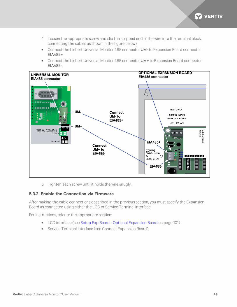
4. Loosen the appropriate screw and slip the stripped end of the wire into the terminal block,connecting the cables as shown in the figure below):
• Connect the Liebert Universal Monitor 485 connector UM- to Expansion Board connectorEIA485+.
• Connect the Liebert Universal Monitor 485 connector UM+ to Expansion Board connectorEIA485-.
5. Tighten each screw until it holds the wire snugly.
5.3.2 Enable the Connection via Firmware
After making the cable connections described in the previous section, you must specify the ExpansionBoard as connected using either the LCD or Service Terminal Interface.
For instructions, refer to the appropriate section:
• LCD interface (see Setup Exp Board - Optional Expansion Board on page 101)
• Service Terminal Interface (see Connect Expansion Board)
Vertiv | Liebert® Universal Monitor™ User Manual | 49

Vertiv | Liebert® Universal Monitor™ User Manual | 50
This page intentionally left blank.
6 OVERVIEW OF MENUSThere are two ways to access the Liebert Universal Monitor: the LCD on the front of the enclosure and theService Terminal Interface, which is accessible through any computer using a communications program.Many viewing and configuration tasks can be performed through either interface, but some are availableonly through the Service Terminal Interface.
• Step-by-step instructions for all functions appear in View Status Options on page 55 throughSystem and Control Options on page 67. These instructions use examples of LCD screens toillustrate most functions, except those not available via the LCD.
• Examples of all Service Terminal Interface screens appear in Service Terminal Interface onpage 107, along with instructions on how to connect to the Service Terminal Interface.
Table 6.1 below lists all Liebert Universal Monitor functions and shows whether they can be performedthrough the LCD interface and where to find information.
Function
Canbe performedvia:
Where to find:
LCDServiceTerminal
Instructions onusing function
Service Terminalscreen examples
VIEW STATUS FUNCTIONS
View Active Alarms x x View Active Alarms on page 56 View Active Alarms
View Alarm Log x x View Alarm Log on page 57 View Alarm Log
View Event Log x x View Event Log on page 59 View Event Log
View Trend Log x x View Trend Log on page 60 View Trend Log
View Input Status x x View Input Status on page 62 View Input Status
View Output Status x x View Output Status on page 63 View Output Status
View Pager Numbers x x View Pager Numbers on page 63 View Pager Numbers
SILENCE ALARM & BACK UP LOGS FUNCTIONS
Silence Alarm (On the LCD, pressany key to silence an alarm) x x Silence Alarm (Service Terminal Interface) on
page 65Silence Alarm (Service TerminalInterface only)
Back Up Log Files — x Back Up Log Files (Service Terminal Interfaceonly) on page 65
Back Up Log Files (Service TerminalInterface only)
SYSTEM & CONTROL FUNCTIONS
Login x x Login on page 67 Login Menu
Setup System x x Setup System - Overview on page 70 Setup Menu
Setup Input x x Setup System - Setup Input on page 70 Setup Input
Setup Common Alarm x x Setup System - Setup Common Alarm onpage 73 Setup Common Alarm
Setup Sensor x x Setup System - Setup Sensor on page 74 Setup Sensor
Setup I/O Matrix x x Setup System - Setup I/O Matrix on page 80 Setup I/O Matrix
Setup Output x x Setup System - Setup Output on page 83 Setup Output
Pager Setup - Pager Number &PIN x x Pager Setup - Pager Number and PIN on
page 89 Pager Setup
Pager Setup - CommunicationsCheck — x Pager Setup - Communications Check (Service
Terminal Interface only) on page 91 Pager Setup
Modem Setup - Initialization String x x Modem Setup - Initialization String on page 85 Modem Setup
Table 6.1 Guide to Liebert Universal Monitor functions
Vertiv | Liebert® Universal Monitor™ User Manual | 51
Function
Canbe performedvia:
Where to find:
LCDServiceTerminal
Instructions onusing function
Service Terminalscreen examples
Modem Setup - Enter LiebertUniversal Monitor Phone Number — x Modem Setup - Additional Features (Service
Terminal Interface only) on page 86 Modem Setup
Modem Setup - Enable ModemDiagnostic Messages — x Modem Setup - Additional Features (Service
Terminal Interface only) on page 86 Modem Setup
Modem Setup - Change ModemDial Prefix — x Modem Setup - Additional Features (Service
Terminal Interface only) on page 86 Modem Setup
Modem Setup - Change ModemHang Up Delay After a Call — x Modem Setup - Additional Features (Service
Terminal Interface only) on page 86 Modem Setup
Setup System Info x x Setup System - Setup System Info on page 92 Setup System Info
Change Password x x Change Password on page 93 Change Password
Change Date & Time/AutomaticDaylight Saving Time x x Change Date & Time/Automatic Daylight
Saving Time on page 94Change Date & Time/AutomaticDaylight Saving Time
Setup Site ID x x Setup Site ID on page 94 Setup Site ID
Connect Battery x x Connect Battery on page 94 Connect Battery
Backup and Upload ConfigurationFile — x Backup and Upload Configuration File (Service
Terminal Interface only) on page 95Backup and Upload Configuration File(Service Terminal Interface only)
Setup Serv Ph Num - Enter PhoneNumber x x Setup Serv Ph Num - Enter Phone Number on
page 96 Setup Service Phone Number
Setup Serv Ph Num -Communications Check — x Setup Serv Ph Num - Communications Check
(Service Terminal Interface only) on page 98 Setup Service Phone Number
Factory Defaults x x Factory Defaults on page 98 Factory Defaults
Perform Firmware Update — x Perform Firmware Update (Service TerminalInterface only) on page 99
Firmware Update (Service TerminalInterface only)
Initiate Remote Alarm Test — 4 Initiate Remote Alarm Test (Service TerminalInterface only) on page 100
Initiate Remote Alarm Test (ServiceTerminal Interface only)
Setup Exp Board - OptionalExpansion Board 4 4 Setup Exp Board - Optional Expansion Board on
page 101 Connect Expansion Board
Manual Output Ctrl 4 4 Manual Output Ctrl on page 101 Override Output
Clear Alarms & Logs 4 4 Clear Alarms & Logs on page 102 Clear Alarms & Logs
Clear Active Alarms 4 4 Clear Active Alarms on page 102 Clear Active Alarms
Clear the Alarm Log 4 4 Clear the Alarm Log on page 103 Clear the Alarm Log
Clear the Event Log 4 4 Clear the Event Log on page 103 Clear the Event Log
Clear the Trend Logs 4 4 Clear the Trend Logs on page 103 Clear the Trend Logs
Table 6.1 Guide to Liebert Universal Monitor functions (continued)
6.1 Opening Screen Overview
The Liebert Universal Monitor displays the Opening Screen at startup, as shown in Figure 6.1 on thefacing page.
• If any alarms are active, the Current Alarm screen appears. (Pressing any key on the LCDkeypad will silence the audible alarm.)
• If any analog input sensors are connected, the LCD screen will alternately display the OpeningScreen and a screen showing the analog value of each sensor.
If no alarms are present, the Main Menu appears.
Vertiv | Liebert® Universal Monitor™ User Manual | 52
6.2 Main Menu Overview
The Main Menu offers access to all functions within the panel. As shown in 6.2 above, the functions areorganized into three sections with step-by-step instructions.
Section Description
View Status Options on page 55 - View Status Options (both LCD andService Terminal Interface)
These features are available to all users. This permits all personnel to checkthe status of any monitored equipment or location. From this menu, any usermay:View current monitoring data—active alarms and the status of inputs andoutputsView data stored in alarm, event and trend logsView pager numbers
Silence Alarm & Backup Log Files (Service Terminal Interface) onpage 65 - Silence Alarm & Backup Log Files (Service TerminalInterface only)
These features—available via the Service Terminal Interface only—allowusers to:Silence the audible alarmBack up the alarm, event and trend logs
System and Control Options on page 67 - System and Control Options(some functions available via Service Terminal Interface only)
These options require a password. Authorized users may:Configure the Liebert Universal MonitorOverride automatic control of outputs to force an output ON or OFFClear active alarms and delete all records in the alarm, event and trend logs
Table 6.2 Primary Functions Overview
6.3 LCD Menu Overview
Figure 6.1 below is an overview of the initial screens available through the LCD interface. For comparableinformation about the Service Terminal Interface screens, see Overview of Menus on page 51.
Figure 6.1 LCDMenu overview
Vertiv | Liebert® Universal Monitor™ User Manual | 53

Vertiv | Liebert® Universal Monitor™ User Manual | 54
This page intentionally left blank.
7 VIEW STATUS OPTIONSNOTE: For ease of understanding, this section uses the LCD interface to illustrate most instructions,except for features that are available only through the Service Terminal Interface. All Service TerminalInterface screens appear in Service Terminal Interface on page 107.
The View Status menu allows any user to view currently active alarms, monitoring data stored in thealarm, event and trend logs, the status of all inputs and outputs, and the four pager numbers. The arrowsare used to scroll through the menu. The Enter key is used to select the menu item.
This section presents step-by-step instructions for each of the following options:
• View Active Alarms• View Alarm Log• View Event Log• View Trend Log• View Input Status• View Output Status• View Pager Numbers
Figure 7.1 on the next page shows the main options available from the View Status menu.
Vertiv | Liebert® Universal Monitor™ User Manual | 55
Figure 7.1 Menu overview - View Status menu
7.1 View Active Alarms
The Active Alarm screen displays all alarms that are occurring, up to a maximum of 33.
A Current Alarm screen appears automatically whenever an alarm occurs—except during setup. Thisscreen can display only the two most recent active alarms. To view any other active alarms, use the ViewActive Alarms feature.
You may view active alarms at any time by using the following steps:
• From the Main Menu, use the arrows to choose View Status, as shown below, and then pressEnter.
• From the View Status Menu, use the arrows to choose View Active Alarms and press Enter.
Vertiv | Liebert® Universal Monitor™ User Manual | 56
7.1.1 Active Alarms
The Active Alarms screen displays up to 33 records; it shows any active alarm and any Latched alarm thathas not been cleared. Examples of alarms include inputs in alarm status, a low battery condition and a lossof connection to an analog input. When any alarms are present, the Active Alarms screen showsdescriptive details for each alarm:
• the source of the alarm (for example, SENSOR_1 or BATTERY)
• the status of an input or output (101.0 DEG)
• a brief description of the problem (HIGH SETPOINT ALARM or CHECK BATTERY)
If there are no active alarms, the screen displays the message:
NO ALARMS PRESENT
Viewing Additional Screens
There may be up to 33 records of alarm data.
• To view additional records, use the arrows.
• To return to the previous screen, press the ESC key.
Clearing Active Alarms
To clear all active alarms, see Clear Alarms & Logs on page 102. Alarm records are stored in the Alarm Log.
7.2 View Alarm Log
The Alarm Log contains up to 99 records of alarms that have occurred. Records are added to this log asalarms occur.
To view the Alarm Log:
• From the Main Menu, use the arrows to choose View Status, then press Enter.
• From the View Status Menu, use the arrows to choose View Alarm Log, then press Enter.
Vertiv | Liebert® Universal Monitor™ User Manual | 57
7.2.1 Alarm Log
The Alarm Log screen displays up to 99 records showing alarm data, including input alarms and otherconditions, such as loss of power or low battery. If the log contains any alarm records, the Alarm Logscreen displays details for each alarm:
• the source of the alarm (for example, SENSOR_2 or MODEM)
• the status of an input or output (80.0 DEG)
• a brief description of the problem (HIGH SETPOINT ALARM or INTERNAL FAULT)
• the date and time the alarm occurred
Table 7.1 below shows conditions that the alarm log records for digital inputs and analog inputs and inthe panel itself.
SOURCE Digital Input Analog Input Panel
CONDITIONSRECORDED
ALARM
NORMAL
HIGH SETPOINT ALARM
LOW SETPOINT ALARM
RETURN TO NORMAL
SENSOR PROBLEM (denoted by dashes ------)
LOSS OF POWER
LOW BATTERY
CHECK BATTERY
BATTERY UNPLUGGED
ALARM SILENCED
MODEM INTERNAL FAULT
ALARMS CLEARED
EXP BRD LOSS OF COMM
EXP BRD RESTORE COMM
Table 7.1 Alarm log conditions
If there are no alarms in the log, the screen displays the message:
NO ALARMS
Viewing Additional Screens
There may be up to 99 records of alarm data.
• To view additional records, use the arrows.
• To return to the previous screen, press the ESC key.
7.2.2 Backing Up the Alarm Log (Service Terminal Interface only)
The alarm log is stored as a file in the Liebert Universal Monitor; it can hold no more than 99 records.When the log is full, the oldest records are deleted from the end of the file as new alarm records are addedat the beginning.
You may back up the alarm log file to a remote computer using the Service Terminal Interface, asdescribed in Back Up Log Files (Service Terminal Interface only) on page 65.
To delete all records in the alarm log, see Clear Alarms & Logs on page 102.
Vertiv | Liebert® Universal Monitor™ User Manual | 58
7.3 View Event Log
In addition to alarms, the Liebert Universal Monitor tracks other changes in the Event Log to assist userswith verifying operational and troubleshooting problems. Events reflect changes in the status of an inputthat is defined as an event or the change of state of an output (i.e., manually forced ON or OFF). Otherevents may be informational, such as a user login or an unsuccessful page attempt. The Event Logcontains up to 99 records of events, which are added as they occur.
To view the Event Log:
• From the Main Menu, use the arrows to choose View Status, then press Enter.
• From the View Status Menu, use the arrows to choose View Event Log, then press Enter.
7.3.1 Event Log
The Event Log screen displays up to 99 recent events. If the log contains any event records, the EventLog screen displays details for each event:
• the event source (for example, PAGER or OUTPUT01)
• the status of an input or output (MAN ON)
• a brief description of the event (UNSUCCESSFUL PAGE or CONTACT CLOSED)
• the date and time the event occurred
Table 7.2 below shows conditions that the event log records for inputs and outputs and in the panelitself.
SOURCE Digital Input Analog Input Digital Output Panel
CONDITIONSRECORDED
EVENT
NORMAL
HIGH SETPOINT EVENT
LOW SETPOINT EVENT
RETURN TO NORMAL
SENSOR PROBLEM
(denoted by dashes ------)
MAN ON
MAN OFF
AUTO
HW MAN ON
ON
OFF
ALARMS CLEARED
ALARM SILENCED
DIAL OUT TEST PASSED
DIAL OUT TEST FAILED
UNSUCCESSFUL PAGE
MODEM RESET
TIME & DATE SET
USER LOGIN
Table 7.2 Event log conditions
If there are no records in the log, the screen displays the message:
NO EVENTS
Viewing Additional Screens
There may be up to 99 records of event data.
• To view additional records, use the arrows.
• To return to the previous screen, press the ESC key.
Vertiv | Liebert® Universal Monitor™ User Manual | 59

7.3.2 Backing Up the Event Log (Service Terminal Interface only)
The event log is stored as a file in the Liebert Universal Monitor; it can hold no more than 99 records.When the log is full, the oldest records are deleted from the end of the file as new event records are addedat the beginning.
You may back up the event log file to a remote computer using the Service Terminal Interface, asdescribed in Back Up Log Files (Service Terminal Interface only) on page 65.
To delete all records in the event log, see Clear Alarms & Logs on page 102.
7.4 View Trend Log
The Liebert Universal Monitor takes readings of configured analog input sensors at regular intervals andstores them in four separate trend logs, one for each sensor. The time interval is 30 minutes. Each logcontains up to 100 records.
Follow these steps to select a sensor and view its trend log:
7.4.1 Select a Sensor
To select a sensor:
• From the Main Menu, use the arrows to choose View Status, then press Enter.
• From the View Status Menu, use the arrows to choose View Trend Log, then press Enter.
• From the Sensor Selection Menu, use the arrows to choose the sensor you want to view—Sensor_1 in the example below—and press Enter.
Vertiv | Liebert® Universal Monitor™ User Manual | 60

7.4.2 View a Trend Log
The Trend Log screen displays up to 100 records for the selected sensor. If the log contains records, thescreen displays details for each reading:
• the name of the selected sensor (for example, SENSOR_1)
• the reading (75.4 DEG)
• a brief description of the reading status (NORMAL)
• the date and time of the reading
Table 7.3 below shows conditions that the trend log records for analog inputs. Each analog input has itsown trend log.
SOURCE Analog Input
CONDITIONSRECORDED
LOW SETPOINT ALARM
LOW SETPOINT EVENT
HIGH SETPOINT ALARM
HIGH SETPOINT EVENT
RETURN TO NORMAL
NORMAL
SENSOR PROBLEM (denoted by dashes ------)
Table 7.3 Trend log conditions
If there are no records in the log, the screen displays the message:
NO TRENDS
Viewing Additional Screens
There may be up to 100 records of trend data for the selected sensor.
• To view additional records, use the arrows.
• To return to the previous screen, press the ESC key.
7.4.3 Backing Up the Trend Log (Service Terminal Interface only)
The four trend logs are stored as files in the Liebert Universal Monitor, with a maximum of 100 records persensor. When a log is full, the oldest records are deleted from the end of the file as new trend records areadded at the beginning.
You may back up each trend log file to a remote computer using the Service Terminal Interface, asdescribed in Back Up Log Files (Service Terminal Interface only) on page 65.
To delete all records in the trend logs, see Clear Alarms & Logs on page 102.
Vertiv | Liebert® Universal Monitor™ User Manual | 61
7.5 View Input Status
The Input Status option allows you to view the current status of all inputs: the four analog sensor inputsand the eight digital inputs. If the optional Expansion Board is used, the additional 16 digital inputs canalso be viewed.
To view the Input Status:
• From the Main Menu, use the arrows to choose View Status, then press Enter.
• From the View Status Menu, use the arrows to choose View Input Status, then press Enter.
7.5.1 Input Status
The Input Status screen displays the status of each analog sensor and digital input.
Analog Sensor Inputs
The following details are displayed for analog sensor inputs:
• the name of the analog sensor input (for example, SENSOR_1)
• the current reading (+80.00 DEG)—values are updated constantly while being viewed
There are three possible states for an analog input, as shown in Table 7.4 below.
State Description
Functional Reading—-for example, +80.00 DEG or +79.50 RH
Problem with connection Dashes (------)
Not configured Blank
Table 7.4 Analog input states
NOTE: If the status displays dashes (------), the Liebert Universal Monitor was unable to take areading. There may be a connection problem. If the status is blank, the sensor is not configured asbeing connected.
Digital Inputs
The following details appear for digital inputs:
• the name of the digital input (for example, INPUT_01)
• the current status (NORMAL)—values are updated constantly while being viewed
There are three possible states for a digital input, as shown in Table 7.5 below.
State Description
NORMAL In normal state
ALARM In alarm status (for an input configured as alarmable)
EVENT An event has occurred (for an input configured as an event)
Table 7.5 Digital input states
Vertiv | Liebert® Universal Monitor™ User Manual | 62
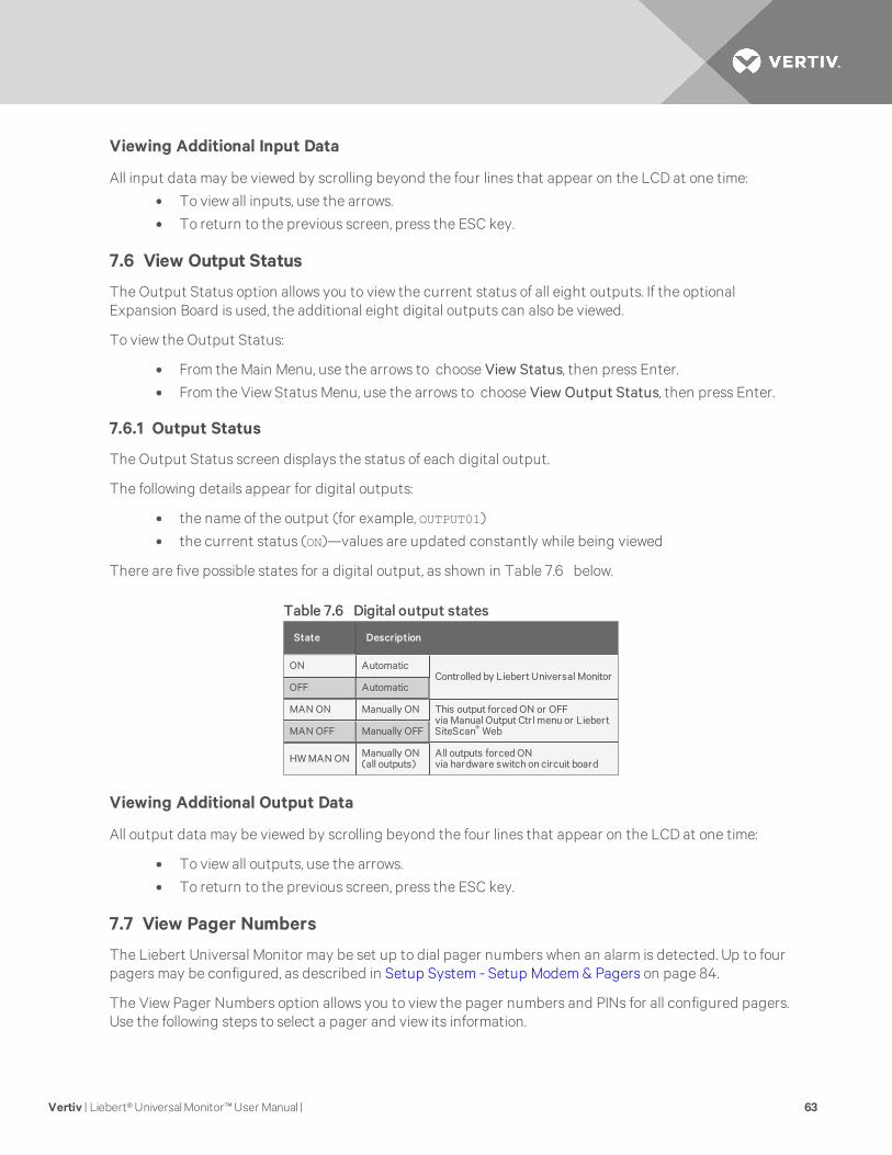
Viewing Additional Input Data
All input data may be viewed by scrolling beyond the four lines that appear on the LCD at one time:
• To view all inputs, use the arrows.
• To return to the previous screen, press the ESC key.
7.6 View Output Status
The Output Status option allows you to view the current status of all eight outputs. If the optionalExpansion Board is used, the additional eight digital outputs can also be viewed.
To view the Output Status:
• From the Main Menu, use the arrows to choose View Status, then press Enter.
• From the View Status Menu, use the arrows to choose View Output Status, then press Enter.
7.6.1 Output Status
The Output Status screen displays the status of each digital output.
The following details appear for digital outputs:
• the name of the output (for example, OUTPUT01)
• the current status (ON)—values are updated constantly while being viewed
There are five possible states for a digital output, as shown in Table 7.6 below.
State Description
ON AutomaticControlled by Liebert Universal Monitor
OFF Automatic
MAN ON Manually ON This output forced ON or OFFvia Manual Output Ctrl menu or LiebertSiteScan® WebMAN OFF Manually OFF
HW MAN ON Manually ON(all outputs)
All outputs forced ONvia hardware switch on circuit board
Table 7.6 Digital output states
Viewing Additional Output Data
All output data may be viewed by scrolling beyond the four lines that appear on the LCD at one time:
• To view all outputs, use the arrows.
• To return to the previous screen, press the ESC key.
7.7 View Pager Numbers
The Liebert Universal Monitor may be set up to dial pager numbers when an alarm is detected. Up to fourpagers may be configured, as described in Setup System - Setup Modem & Pagers on page 84.
The View Pager Numbers option allows you to view the pager numbers and PINs for all configured pagers.Use the following steps to select a pager and view its information.
Vertiv | Liebert® Universal Monitor™ User Manual | 63

7.7.1 Select a Pager
To select a pager:
• From the Main Menu, use the arrows to choose View Status, then press Enter.
• From the View Status Menu, use the arrows to choose View Pager Numbers, then press Enter.
• From the Pager Selection screen, use the arrows to choose the pager you want to view—PagerNumber 1 in the example below—and press Enter.
• Use the following steps to view a pager number or PIN for the selected pager.
7.7.2 View a Pager Number
To view a pager number:
• Choose View Pager Number from the Pager Menu and press Enter.
• The Pager Number screen displays the number that is configured for the selected pager.
In the example below, the telephone number is preceded by A to dial an alphanumeric pagerand includes a comma (,) to pause two seconds after dialing “1” before proceeding to dial thearea code and number. To change this number, see Pager Setup - Pager Number and PIN onpage 89.
• Press ESC to return to the Pager Menu.
7.7.3 View a Pager PIN
To view a pager PIN:
• Choose View Pager PIN from the Pager Menu and press Enter.
• The Pager PIN screen displays the PIN that is configured for the selected pager. To changethis number, see Setup System - Setup Modem & Pagers on page 84.
• Press ESC to return to the Pager Menu.
Vertiv | Liebert® Universal Monitor™ User Manual | 64

8 SILENCE ALARM & BACKUP LOG FILES (SERVICETERMINAL INTERFACE)This section describes two features that are available in the Service Terminal Interface:
• Silence Alarm
• Backup Log Files
8.1 Silence Alarm (Service Terminal Interface)
The Silence Alarm menu item allows you to silence the audible alarm and reset the Common Alarm Relayoutput if the common alarm is configured to reset with silence.
This menu item is available only through the Service Terminal Interface and Liebert SiteScan® Webconnection.
NOTE: An alarm may also be silenced by pressing any key on the LCD keypad on the front of theLiebert Universal Monitor. The LCDdoes not offer Silence Alarm as a menu item.
To silence the alarm remotely through the Service Terminal Interface:
• Connect to the Liebert Universal Monitor either from a remote computer or through the RS232port (see Connecting to the Service Terminal Interface on page 109).
• At the Main Menu, enter 8 (Silence Alarm).
• At the Silence Alarm menu, enter 1 to silence the audible alarm immediately. (To exit withoutsilencing the alarm, enter 2 or press the Escape key.)
• A confirmation message appears: “Alarm has been silenced.”
NOTE: Through Liebert SiteScan Web, this option is available via the Liebert Universal Monitor GraphicScreen.
8.2 Back Up Log Files (Service Terminal Interface only)
The Liebert Universal Monitor maintains three types of logs—alarm, event and trend—that may bebacked up to a remote computer.
This feature is available only through the Service Terminal Interface.
To back up any of the alarm, event or trend logs:
1. Connect to the Liebert Universal Monitor either from a remote computer or through the RS232port (see Connecting to the Service Terminal Interface on page 109).
2. At the Main Menu, enter 9 (Backup Log Files).
3. At the Backup Log Files menu, enter a number for the type of file you want to back up:
• Enter 1 to back up the Alarm Log
• Enter 2 to back up the Event Log
• Enter 3 to back up the Trend Log for the first sensor (Sensor_1)
• Enter 4 to back up the Trend Log for the second sensor (Sensor_2)
• Enter 5 to back up the Trend Log for the third sensor (Sensor_3)
• Enter 6 to back up the Trend Log for the fourth sensor (Sensor_4)
Vertiv | Liebert® Universal Monitor™ User Manual | 65

4. At the prompt to initiate a backup of the selected log file, enter Y (Yes - begin) or N (No -cancel). The current setting appears in brackets.
NOTE: The following instructions refer to the Microsoft® Windows® HyperTerminal program. Thesesteps may vary for other communications programs.
5. At the top of the HyperTerminal window, click Transfer, then Receive File.
6. In the Receive File window:
• In the Place Received File in the Following Folder box, enter the name and location of thefolder where the configuration file should be placed—for example, C:\downloads—or clickon the Browse button to locate the folder.
• In the Use Receiving Protocol box, select Xmodem from the drop-down list.
• Click on the Receive button. (To close the window without backing up the file, click onClose or Cancel.)
7. In the Receive Filename window, enter a name for the log file—Alarm.log in the example above.
8. When the transfer is complete, a confirmation message appears in the Service TerminalInterface window: “Backup Successful.”
9. The display returns to the Backup Log Files menu. You may choose another type of log file toback up (return to Step 3) or press 7 (or Escape) to return to the Main Menu.
After backing up a log file, you may want to delete all records in the Universal Monitor’s log of that type.See Clear Alarms & Logs on page 102 for details.
Vertiv | Liebert® Universal Monitor™ User Manual | 66
9 SYSTEM AND CONTROL OPTIONSNOTE: For ease of understanding, this section uses the LCD interface to illustrate most instructions,except for features that are available only through the Service Terminal Interface. All Service TerminalInterface screens appear in Service Terminal Interface on page 107.
The System and Control menu allows you to configure the Liebert Universal Monitor—setting up inputsand outputs and an input/output matrix to trigger actions, the modem and pagers, and system featuressuch as date and time. This menu also provides a vehicle for manually changing the state of an output toON or OFF, clearing active alarms and deleting records from the Liebert Universal Monitor’s alarm log,event log and trend logs.
The arrows are used to scroll through the menu. The Enter key is used to select the menu item and enternew information. Table 9.1 below shows characters that may be entered in labels and values.
Alphanumeric Special characters
A-Z, 0-9 space [ ] ^ _ ! " # $ % & ( ) * + - / , . ; < = > @
Table 9.1 Valid characters for data entry
The System and Control options require a password to prevent unauthorized users from making changesto the system.
This section presents step-by-step instructions for each of the following:
• Login - enter the password
• Setup System - configure inputs, outputs, modem, pagers, system features
• Manual Output Ctrl - manually override automatic control of outputs; release the override
• Clear Alarms & Logs - clear active alarms; delete records from the alarm, event and trend logs
NOTE: If an alarm occurs while a user is logged on, the LCDbacklight will flash and the audible alarmwill sound. To obtain specific information about the alarm, you must access the Active Alarm screen(see View Active Alarms on page 56) or the Alarm Log (see View Alarm Log on page 57).
9.1 Login
Users must enter a password to access any of the system and control options. The password consists offour characters (see Table 9.1 above for valid characters). (To set up or change the password, seeChange Password on page 93.)
To log in:
• From the Main Menu, use the arrows to choose System and Control, then press Enter.
• Use the arrows to choose System and Control, and press Enter. The Login menu appears.
• To enter your password:
• Use the arrows to choose a character.
• Press Enter to advance to the next character position.
• When finished, press Enter again.
Vertiv | Liebert® Universal Monitor™ User Manual | 67
The System and Control Menu appears next, with these options that are described in the followingsections:
• Setup System (Setup System - Overview on page 70 - Setup System - Setup System Info onpage 92)
• Manual Output Ctrl (Manual Output Ctrl on page 101)
• Clear Alarms & Logs (Clear Alarms & Logs on page 102)
NOTE: If, after logging in, you press the ESC key to return to a previous screen that is not password-protected, you must log in again, including entering your password if you wish to access password-protected functions.
Figure 9.1 on the facing page shows the main options available from the System & Control menu.
Vertiv | Liebert® Universal Monitor™ User Manual | 68
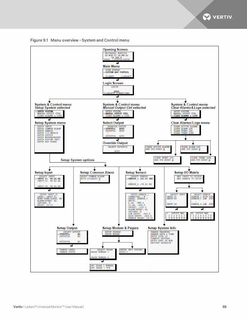
Figure 9.1 Menu overview - System and Control menu
Vertiv | Liebert® Universal Monitor™ User Manual | 69
9.2 Setup System - Overview
The Setup System screen displays seven options that allow you to configure input and output devicesand their relationships, the common alarm, the modem, pagers to be dialed when alarms occur, and avariety of system details, such as login password and system date and time:
• Setup Input
• Setup Common Alarm
• Setup Sensor
• Setup I/O Matrix
• Setup Output
• Setup Modem & Pagers
• Setup System Info
• Setup Exp Board
9.3 Setup System - Setup Input
The Liebert Universal Monitor has eight digital input points that may be configured individually. If theoptional Expansion Board is used, an additional 16 digital inputs may also be configured. These inputsmay have a wide variety of Liebert or other manufacturers’ equipment connected for monitoring.
To configure a digital input:
Log In and Choose Setup System
• From the Main Menu, use the arrows to choose System and Control, then press Enter (seeLogin on page 67 for help).
• Enter your password at the Login screen.
• From the System and Control Menu, use the arrows to choose Setup System, then press Enter.
Select a Digital Input to Configure
• From the Setup System Menu, shown below, use the arrows to choose Setup Input and pressEnter.
• From the Select Input Menu, choose the input you want—for example, Input_01—and pressEnter.
Table 9.2 on the facing page shows the digital input features you may change, along with the defaultsettings: you may change the name of the input, define it as normally open or closed, and specify it asalarmable or as an event.
• Alarmable inputs may be defined as either Unlatched or Latched.
• Event status allows you to monitor a digital input’s state—and use a change in state to initiatean action through an output, if desired—without triggering an alarm. Events are alwaysUnlatched.
• You may also specify a delay before the Liebert Universal Monitor responds to an alarm orevent.
Use the steps following Table 9.2 on the facing page to change the default settings for any digital input.
Vertiv | Liebert® Universal Monitor™ User Manual | 70
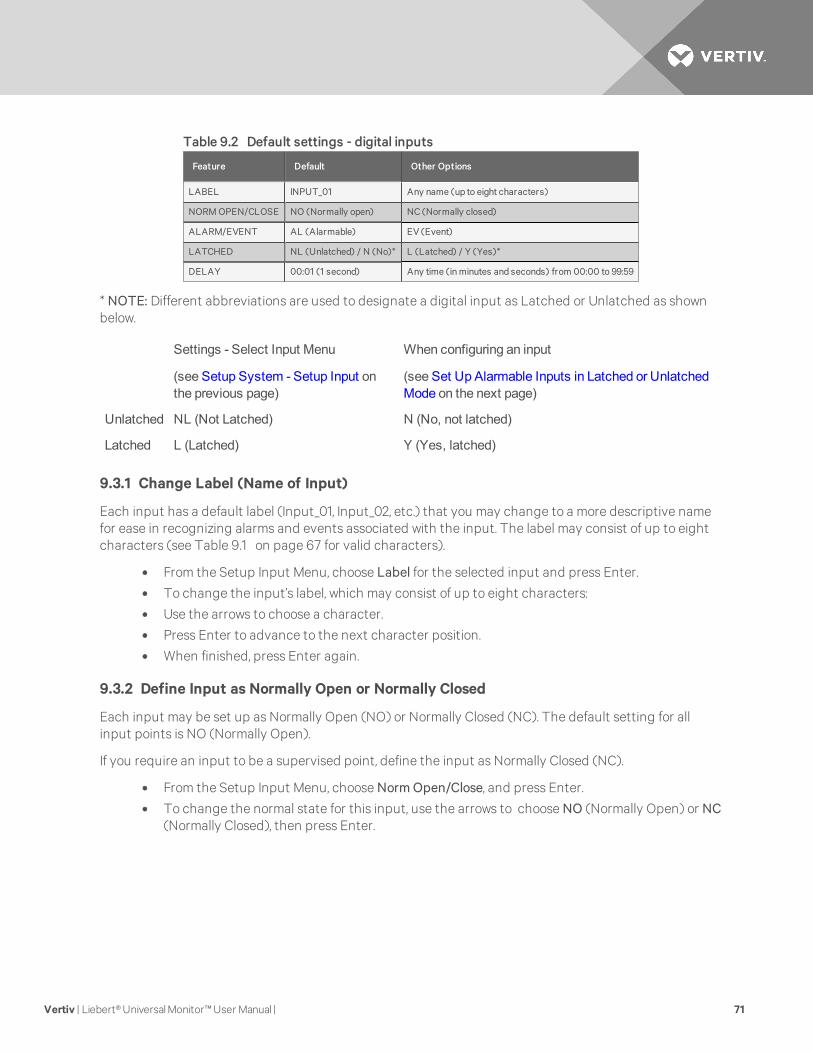
Feature Default Other Options
LABEL INPUT_01 Any name (up to eight characters)
NORM OPEN/CLOSE NO (Normally open) NC (Normally closed)
ALARM/EVENT AL (Alarmable) EV (Event)
LATCHED NL (Unlatched) / N (No)* L (Latched) / Y (Yes)*
DELAY 00:01 (1 second) Any time (in minutes and seconds) from 00:00 to 99:59
Table 9.2 Default settings - digital inputs
* NOTE: Different abbreviations are used to designate a digital input as Latched or Unlatched as shownbelow.
Settings - Select Input Menu
(see Setup System - Setup Input onthe previous page)
When configuring an input
(see Set Up Alarmable Inputs in Latched or UnlatchedMode on the next page)
Unlatched NL (Not Latched) N (No, not latched)
Latched L (Latched) Y (Yes, latched)
9.3.1 Change Label (Name of Input)
Each input has a default label (Input_01, Input_02, etc.) that you may change to a more descriptive namefor ease in recognizing alarms and events associated with the input. The label may consist of up to eightcharacters (see Table 9.1 on page 67 for valid characters).
• From the Setup Input Menu, choose Label for the selected input and press Enter.
• To change the input’s label, which may consist of up to eight characters:
• Use the arrows to choose a character.
• Press Enter to advance to the next character position.
• When finished, press Enter again.
9.3.2 Define Input as Normally Open or Normally Closed
Each input may be set up as Normally Open (NO) or Normally Closed (NC). The default setting for allinput points is NO (Normally Open).
If you require an input to be a supervised point, define the input as Normally Closed (NC).
• From the Setup Input Menu, choose Norm Open/Close, and press Enter.
• To change the normal state for this input, use the arrows to choose NO (Normally Open) or NC(Normally Closed), then press Enter.
Vertiv | Liebert® Universal Monitor™ User Manual | 71

9.3.3 Define Input as Alarmable or Event
Each digital input may be defined as Alarmable (AL) or as an Event (EV).
• For a digital input defined as alarmable, the following alarm reactions occur when the status ofthe monitored input device changes: the LCD flashes, the audible horn sounds, configuredpager numbers will be notified and a record is entered in the Alarm Log.
• For a digital input defined as an event, the status change is recorded in the Event Log.
By default, all digital inputs are set up as AL (Alarmable).
• From the Setup Input Menu, choose Alarm/Event, and press Enter.
• To change the type of digital input, use the arrows to choose AL (Alarmable) or EV (Event),then press Enter.
9.3.4 Set Up Alarmable Inputs in Latched or Unlatched Mode
Alarmable input points may be set up in Latched mode (Y), which requires the user to clear the LiebertUniversal Monitor alarms after an alarm has occurred, or Unlatched mode (N), in which alarms willautomatically clear after a return-to-normal state. The default setting for alarmable inputs is N (Unlatched). Any input defined as an event is automatically Unlatched.
A digital input defined as Latched does not reset automatically after an alarm. It will remain in thetriggered position even after the monitored device returns to normal. After an alarm, the user mustmanually reset Latched inputs, as described in Clear Active Alarms on page 102. This also means that anydigital outputs linked to a Latched digital input will remain triggered until the input is manually reset.
A digital input defined as Unlatched will automatically track the status of the monitored device. No actionby the user is required.
• From the Setup Input Menu, choose Latched, and press Enter.
• To change this feature, use the arrows to choose Y (Yes - Latched) or N (No - Unlatched), thenpress Enter.
NOTE: Only alarmable input points may be set up as Latched. If you attempt to set up an event asLatched, the message shown below appears. Press the ESC key to return to the previous screen tocontinue configuring the digital input.
The only way to reset latched alarms is by clearing active alarms. This step is required to return latchedpoints to their normal state. For details, see Clear Active Alarms on page 102.
Vertiv | Liebert® Universal Monitor™ User Manual | 72
9.3.5 Set Up Delay Time
Each input may be set up with a specified time delay between the occurrence of an alarm or event—amonitored device changes state—and any response by the Liebert Universal Monitor. This feature canprevent needless responses to transient conditions.
This delay is the amount of time that must elapse before the Liebert Universal Monitor acknowledges thechange of state in the monitored device and takes any further action, such as dialing configured pagers.The default time delay is 1 second (displayed as 00 MIN : 01 SEC).
The time delay applies only when a monitored device changes from its normal state—for example, theLiebert Universal Monitor detects a closed contact that is defined as Normally Open.
When the monitored device returns to its normal state, the Liebert Universal Monitor acknowledges thechange of state immediately.
• From the Setup Input Menu, choose Delay, and press Enter.
• To change the time delay in minutes and seconds (in the range of 00:00 to 99:59):
• For minutes (MIN), press and hold one of the arrow keys scroll through the numbers 00-99.
• Press Enter to advance to seconds (SEC).
• For seconds (SEC), press and hold one of the arrow keys scroll through the numbers 00-59.
• When finished, press Enter again.
9.4 Setup System - Setup Common Alarm
The audible alarm sounds after the Liebert Universal Monitor detects an alarm condition in any input thathas been defined as alarmable, including digital and analog sensor inputs. Once the alarm is silenced,there are two options:
• By default, the common alarm remains energized until the input alarm is cleared.
• You may change this setting to de-energize the common alarm automatically once the alarm issilenced.
You might want to reset the common alarm with silence if an external alarm—for example, a horn—isconnected to the common alarm output contacts.
You might not want to reset the common alarm contacts (let contacts reflect/track alarms) and simplysilence the audible horn.
To change the common alarm setting:
Log In and Choose Setup System
• From the Main Menu, use the arrows to choose System and Control, then press Enter (seeLogin on page 67 for help).
• Enter your password at the Login screen.
• From the System and Control Menu, use the arrows to choose Setup System, then press Enter.
Vertiv | Liebert® Universal Monitor™ User Manual | 73
Change to Reset (Y) or Not Reset (N)
• From the Setup System Menu, use the arrows to choose Setup Common Alarm and pressEnter.
• By default, the common alarm is set up not to reset automatically when the alarm is silenced(N). To change this setting, use the arrows to choose Y (Yes - reset with silence) or N (No - notreset), then press Enter.
9.5 Setup System - Setup Sensor
The Liebert Universal Monitor has four analog sensor input points that may be configured individually.The panel monitors connected equipment for any 4-20 mA input—for example, temperature andhumidity.
To configure a sensor:
Log In and Choose Setup System
• From the Main Menu, use the arrows to choose System and Control, then press Enter (seeLogin on page 67 for help).
• Enter your password at the Login screen.
• From the System and Control Menu, use the arrows to choose Setup System, then press Enter.
Select a Sensor to Configure
• From the Setup System Menu, shown below, use the arrows to choose Setup Sensor and pressEnter.
• From the Select Sensor Menu, choose the sensor you want—for example, Sensor_1—and pressEnter.
Table 9.3 on the facing page shows sensor features that may be changed, along with the default settings.By default, sensor inputs are not connected.
To activate a sensor input, you must specify it as connected and enter corresponding values for 4 and20 mA, as well as high and low setpoints. Other features that may be altered include the name of thesensor, the abbreviation for the units, and defining the sensor as alarmable or as an event.
• Alarmable sensors may be Latched (Y) or Unlatched (N).
• Event status allows you to monitor a sensor’s high and low setpoints—and use those setpointsto change the status of an output, if desired—without triggering an alarm. Events are alwaysUnlatched.
• You may also specify a time delay before the Liebert Universal Monitor responds to an alarm orevent.
Use the steps following Table 9.3 on the facing page to change the default settings for any analog sensorinput.
Vertiv | Liebert® Universal Monitor™ User Manual | 74

Feature Default Other Options
CONNECTED* N (Not connected)* Y (Connected)**
LABEL SENSOR_1 Any name (up to eight characters)
UNITS Blank Any units (up to three characters)
4 mA -999.9 Can define up to two decimal places—forexample, -99.99
20 mA +999.9 Can define up to two decimal places—forexample, +99.99
OFFSET +000.0 Can define up to two decimal places—forexample, +00.00
ALARM/EVENT AL (Alarmable) EV (Event)
LATCHED N (Unlatched) Y (Latched)
LOW SETPT -0999.9 Can define up to two decimal places—forexample, -999.99
HIGH SETPT +0999.9 Can define up to two decimal places—forexample, +999.99
SENSOR DELAY 00:01 (1 second) Any time (in minutes and seconds) from 00:00to 99:59
* If a sensor is configured as N (Not connected), the display will show an empty reading (blank spaces).
** If a sensor is configured as Y (Connected) and is functioning properly, the display will show a reading. If the connected sensor is not functioningproperly, the display will show dashes (------) indicating a problem.
Table 9.3 Default settings - analog sensor inputs
9.5.1 Identify the Sensor as Connected
To make use of an analog sensor, you must specify it as Connected (Y). By default, analog sensors are Notconnected (N).
• From the Setup Sensor Menu, choose Connected, and press Enter.
• To change this feature, use the arrows to choose Y (Yes - Connected) or N (No - Notconnected), then press Enter.
9.5.2 Change Sensor Label (Name)
Each sensor has a default label (Sensor_1, Sensor_2, etc.) that you may change to a more descriptive name.The label may consist of up to eight characters (see 9 on page 67 for valid characters).
• From the Setup Sensor Menu, choose Label for the selected sensor and press Enter.
• To change the sensor’s label, which may consist of up to eight characters:
• Use the arrows to choose a character.
• Press Enter to advance to the next character position.
• When finished, press Enter again.
Vertiv | Liebert® Universal Monitor™ User Manual | 75
9.5.3 Change Units Label
For each sensor, you may use a three-character label to specify measurement units, such as DEG (seeTable 9.1 on page 67 for valid characters).
• From the Setup Sensor Menu, choose Units for the selected sensor and press Enter.
• To enter the units label, which may consist of up to three characters:
• Use the arrows to choose a character.
• Press Enter to advance to the next character position.
• When finished, press Enter again.
9.5.4 Change 4 mA Value
For the 4 mA value, enter the smallest value for the range of the sensor—for example, 50°F for atemperature sensor with a range of 50°F to 90°F.
The default value for each sensor is -999.9. Values that can be entered range from -999.9 to +999.9.
To enter a new value:
• From the Setup Sensor Menu, choose 4 mA for the selected sensor and press Enter.
• To change the 4 mA value:
• Use the arrows to choose a character.
• Press Enter to advance to the next character position.
• When finished, press Enter again.
9.5.5 Change 20 mA Value
For the 20 mA value, enter the largest value for the range of the sensor—for example, 90°F for atemperature sensor with a range of 50°F to 90°F.
The default value for each sensor is +999.9. Values that can be entered range from -999.9 to +999.9.
To enter a new value:
• From the Setup Sensor Menu, choose 20 mA for the selected sensor and press Enter.
• To change the 20 mA value:
• Use the arrows to choose a character.
• Press Enter to advance to the next character position.
• When finished, press Enter again.
Vertiv | Liebert® Universal Monitor™ User Manual | 76
9.5.6 Change Offset Value
For the Offset value, enter an adjustment factor—for example, if the sensor reading shows 70°F when theactual temperature is 75°F, the offset might be 5°F.
The default Offset value for each sensor is +000.0. Values that can be entered range from -999.9 to+999.9.
To enter a new value:
• From the Setup Sensor Menu, choose Offset for the selected sensor and press Enter.
• To change the Offset value:
• Use the arrows to choose a character.
• Press Enter to advance to the next character position.
• When finished, press Enter again.
9.5.7 Define Sensor as Alarmable or Event
Each sensor may be defined as Alarmable (AL) or as an Event (EV).
• For a sensor defined as alarmable, the following alarm reactions occur when the high-setpointthreshold is crossed: the LCD flashes, the audible horn sounds, configured pager numbers willbe notified and a record is entered in the Alarm Log.
• For a sensor defined as an event, the high-setpoint occurrence is recorded in the Event Log.
By default, all sensors are set up as AL (Alarmable).
• From the Setup Sensor Menu, choose Alarm/Event, and press Enter.
• To change the type of sensor, use the arrows to choose AL (Alarmable) or EV (Event), thenpress Enter.
Vertiv | Liebert® Universal Monitor™ User Manual | 77
9.5.8 Set Up Alarmable Sensors in Latched or Unlatched Mode
Alarmable sensor points may be set up in Latched mode (Y), requiring the user to clear the LiebertUniversal Monitor alarms after an alarm has occurred, or Unlatched mode (N), meaning that alarms willautomatically clear after a return-to-normal state. The default setting for alarmable sensors is N (Unlatched). Any sensor defined as an event is automatically Unlatched.
A sensor defined as Latched does not reset automatically after an alarm. It will remain in the triggeredposition even after the monitored sensor returns to normal. After an alarm, the user must manually resetLatched sensors, as described in Clear Active Alarms on page 102. This also means that any digitaloutputs linked to a Latched sensor will remain triggered until the sensor is manually reset.
A sensor defined as Unlatched will automatically track the status of the monitored sensor. No action bythe user is required.
• From the Setup Sensor Menu, choose Latched, and press Enter.
• To change this feature, use the arrows to choose Y (Yes - Latched) or N (No - Unlatched), thenpress Enter.
NOTE: Only alarmable sensors may be set up as Latched. If you attempt to set up an event as Latched,the message shown below appears. Press the ESC key to return to the previous screen to continueconfiguring the digital input.
The only way to reset latched alarms is by clearing active alarms. This step is required to return latchedpoints to their normal state. For details, see Clear Active Alarms on page 102.
9.5.9 Change Low Setpoint
The Low Setpoint value is typically above the 4 mA value for the sensor. For example, if the 4 mA value is50°F, the Low Setpoint might be 60°F. When the sensor crosses below this value, an alarm or event willoccur, depending on the sensor configuration.
The default Low Setpoint for each sensor is -950.0. Values that can be entered range from:
• the 4 mA value + the Offset value (in the example, 50+5=55)
to
• the 20 mA value + the Offset value (in the example, 90+5=95)
To determine these values, see Change 4 mA Value on page 76, Change 20 mA Value on page 76 andChange Offset Value on the previous page.
To enter a new value:
• From the Setup Sensor Menu, choose Low Setpt for the selected sensor and press Enter.
• To change the Low Setpoint:
• Use the arrows to choose a character.
• Press Enter to advance to the next character position.
• When finished, press Enter again.
Vertiv | Liebert® Universal Monitor™ User Manual | 78
9.5.10 Change High Setpoint
The High Setpoint value is typically below the 20 mA value for the sensor. For example, if the 20 mA valueis 90°F, the High Setpoint might be 85°F. When the sensor crosses above this value, an alarm or event willoccur, depending on the sensor configuration.
The default High Setpoint for each sensor is +950.0. Values that can be entered range from:
• the 4 mA value + the Offset value (in the example, 50+5=55)
to
• the 20 mA value + the Offset value (in the example, 90+5=95)
To determine these values, see Change 4 mA Value on page 76, Change 20 mA Value on page 76 andChange Offset Value on page 77.
To enter a new value:
• From the Setup Sensor Menu, choose High Setpt for the selected sensor and press Enter.
• To change the High Setpoint:
• Use the arrows to choose a character.
• Press Enter to advance to the next character position.
• When finished, press Enter again.
9.5.11 Set Up Delay Time
Each sensor may be set up with a specified time delay between the triggering of a high or low setpoint—amonitored sensor crosses the high or low setpoint threshold—and any response by the Liebert UniversalMonitor. This feature can prevent transient conditions from prompting unnecessary responses.
This delay is the amount of time that must elapse before the Liebert Universal Monitor acknowledges thechange in the monitored sensor and takes any further action, such as dialing configured pagers. Thedefault time delay is 1 second (displayed as 00 MIN : 01 SEC).
The time delay applies to the triggering of a high or low setpoint and also after the monitored sensorreturns to its normal state. When the monitored device returns to its normal state, the specified time delaymust elapse before the Liebert Universal Monitor acknowledges the return-to-normal condition.
• From the Setup Sensor Menu, choose Sensor Delay, and press Enter.
• To change the time delay in minutes and seconds (in the range of 00:00 to 99:59):
• For minutes (MIN), press and hold one of the arrow keys scroll through the numbers00-99.
• Press Enter to advance to seconds (SEC).
• For seconds (SEC), press and hold one of the arrow keys scroll through the numbers00-59.
Vertiv | Liebert® Universal Monitor™ User Manual | 79
9.6 Setup System - Setup I/O Matrix
The Setup I/O Matrix menu allows you to configure the Liebert Universal Monitor’s digital and analoginputs to trigger various actions in any or all of the 16 outputs—eight on the main board and anothereight if the optional Expansion Board is used. Each output can be set up to respond to more than onedigital or analog input, including the additional 16 inputs available via the optional Expansion Board.Almost any mapping combination can be used. For example, you may decide to trigger an action inOutput03 when Input_01 goes into alarm, or you might want to generate an action in Output04 whenSensor_1 High Setpoint goes into alarm.To set up the mapping of inputs to outputs:
Log In and Choose Setup System
• From the Main Menu, use the arrows to choose System and Control, then press Enter (seeLogin on page 67 for help).
• Enter your password at the Login screen.
• From the System and Control Menu, use the arrows to choose Setup System, then press Enter.
Select Setup I/O Matrix
• From the Setup System Menu, use the arrows to choose Setup I/O Matrix and press Enter.
• Use the following instructions to set up the mapping of each digital input or analog sensorinput to each output.
9.6.1 Set Up Mapping for a Digital Input
• Use the arrows to choose Map Input To Output from the Map Input/Sensor Menu, and pressEnter.
• From the Select Input Menu, choose the input you want—for example, Input_01—and pressEnter.
Map Input to a Main Board Output
• From the Select Outputs menu, select Map to Main Board if you want to map the selected inputto an output on the Liebert Universal Monitor’s main board. These outputs are identified asOutputs 1-8.
• On the Output Map screen, you may map the selected input to any of the eight outputs (1-8)—or to more than one output, if desired.
To make changes to the mapping:
• If needed, press Enter to advance to the position directly below the output.
• Use the arrows to choose Y (Yes - Mapped to this output) or N (No - Not mapped), thenpress Enter.
• Press Enter to advance to the next position where you want to make a change.
• Use the arrows to choose Y (Yes - Mapped to this output) or N (No - Not mapped), thenpress Enter.
• When finished, press Enter again.
Vertiv | Liebert® Universal Monitor™ User Manual | 80

Map Input to Expansion Board Output
• From the Select Outputs menu, select Map to Exp Board if you want to map the selected inputto an output on the optional Expansion Board. These outputs are identified as Outputs 9-16.
• On the Output Map screen, you may map the selected input to any of the eight outputs (9-16)—or to more than one output, if desired.
To make changes to the mapping:
• If needed, press Enter to advance to the position directly below the output.
• Use the arrows to choose Y (Yes - Mapped to this output) or N (No - Not mapped), thenpress Enter.
• Press Enter to advance to the next position where you want to make a change.
• Use the arrows to choose Y (Yes - Mapped to this output) or N (No - Not mapped), thenpress Enter.
• When finished, press Enter again.
Default Mappings - Digital Inputs to Outputs
Table 9.4 below shows the default mapping of digital inputs to digital outputs.
Digital input By default, mapped to digital output:
Input_01 Output01
Input_02 Output02
Input_03 Output03
Input_04 Output04
Input_05 Output05
Input_06 Output06
Input_07 Output07
Input_08 Output08
NOTE: By default, no Expansion Board inputs are mapped to any outputs.
Table 9.4 Default mapping of digital inputs to digitaloutputs
Vertiv | Liebert® Universal Monitor™ User Manual | 81
9.6.2 Set Up Mapping for an Analog Sensor Input
• Use the arrows to choose Map Sensor To Outpt from the Map Input/Sensor Menu, and pressEnter.
• From the Select Sensor Menu, choose the input you want—for example, Sensor_1 High Stpt—and press Enter.
Map Sensor to Main Board Output
• From the Select Outputs menu, select Map to Main Board if you want to map the selectedsensor to an output on the Liebert Universal Monitor main board. These outputs are identifiedas Outputs 1-8.
• On the Output Map screen, you may map the selected sensor to any of the eight outputs (1-8)—or to more than one output, if desired.
To make changes to the mapping:
• If needed, press Enter to advance to the position directly below the output.
• Use the arrows to choose Y (Yes - Mapped to this output) or N (No - Not mapped), thenpress Enter.
• Press Enter to advance to the next position where you want to make a change.
• Use the arrows to choose Y (Yes - Mapped to this output) or N (No - Not mapped), thenpress Enter.
• When finished, press Enter again.
Map Sensor to Expansion Board Output
• From the Select Outputs menu, select Map to Exp Board if you want to map the selected sensorto an output on the optional Expansion Board. These outputs are identified as Outputs 9-16.
• On the Output Map screen, you may map the selected sensor to any of the eight outputs (9-16)—or to more than one output, if desired.
To make changes to the mapping:
• If needed, press Enter to advance to the position directly below the output.
• Use the arrows to choose Y (Yes - Mapped to this output) or N (No - Not mapped), thenpress Enter.
• Press Enter to advance to the next position where you want to make a change.
• Use the arrows to choose Y (Yes - Mapped to this output) or N (No - Not mapped), thenpress Enter.
• When finished, press Enter again.
Default Mappings - Analog Inputs to Outputs
By default, analog inputs are not mapped to any digital output, as shown in Table 9.5 on the facing page.
Vertiv | Liebert® Universal Monitor™ User Manual | 82
Analog input By default, mapped to digital output:
Sensor_1 (none)
Sensor_2 (none)
Sensor_3 (none)
Sensor_4 (none)
Table 9.5 Default mapping of analog inputs to digital outputs
9.7 Setup System - Setup Output
The Liebert Universal Monitor has eight outputs that may be configured individually. If the optionalExpansion Board is used, its additional eight digital outputs may be renamed. The outputs may have awide variety of Liebert or other manufacturers’ equipment connected for configured responses to inputalarms and events.
To configure an output:
Log In and Choose Setup System
• From the Main Menu, use the arrows to choose System and Control, then press Enter (seeLogin on page 67 for help).
• Enter your password at the Login screen.
• From the System and Control Menu, use the arrows to choose Setup System, then press Enter.
Select an Output to Configure
• From the Setup System Menu, use the arrows to choose Setup Output and press Enter.
• From the Select Output Menu, choose the output you want—for example, Output01—andpress Enter.
Table 9.6 below shows digital output features and default settings. You may change the name of anyoutput. In addition, the Liebert Universal Monitor’s eight outputs may be defined as normally open orclosed.
Use the steps following Table 9.6 below to change the default settings for any digital output.
Feature Default Other Options
LABEL OUTPUT01 Any name (up to eight characters)
NORM OPEN/CLOSE(Main board only) NO (Normally open) NC (Normally closed)
Table 9.6 Default settings - digital outputs
9.7.1 Change Label (Name of Output)
Each output has a default label (Output01, Output02, etc.) that you may change to a more descriptivename. The label may consist of up to eight characters (see Table 9.1 on page 67 for valid characters).
• From the Setup Output Menu, use the arrows to choose Change Label for the selected outputand press Enter.
• To change the output’s label, which may consist of up to eight characters:
• Use the arrows to choose a character.
• Press Enter to advance to the next character position.
• When finished, press Enter again.
Vertiv | Liebert® Universal Monitor™ User Manual | 83
9.7.2 Define Main Board Output as Normally Open / Closed
Each output may be set up as Normally Open (NO) or Normally Closed (NC). The default setting for alloutput points is NO (Normally Open).
• From the Setup Output Menu, choose Change State, and press Enter .
• To change the normal state for this output, use the arrows to choose NO (Normally Open) orNC (Normally Closed), then press Enter .
9.7.3 Set Expansion Board Output by DIP Switch
If you choose Change State from the Setup Output Menu for an Expansion Board output (OUTPUT09-16), the screen displays a message that the state must be set by DIP switch.
Each digital output on the optional Expansion Board has an associated DIP switch that can determine itsoperation in the event of loss of communication with the Liebert Universal Monitor or loss of power.
To configure a digital output jumper for a loss of power:
• Move the switch down to the “OFF” position (factory default) for Normally Open (NO).
• Move the switch up to the “ON” position for Normally Closed (NC).
For more information, see Setting the Digital Output DIP Switches on page 47.
9.7.4 Configure Main Board Output for Loss of Power (“Fail-Safe”)
Each digital output has an associated jumper that can help prevent undesired effects when the controllerboard loses power. For example, without the proper fail-safe jumper setting, a loss of power might close aswitch that is Normally Open (NO)—perhaps shutting off a fan or closing a valve.
This fail-safe jumper setting is unrelated to configuring an output as Normally Open (NO) or NormallyClosed (NC), as described in the previous section, Define Main Board Output as Normally Open / Closedabove.
To configure a digital output jumper for a loss of power:
• Set the jumper in the “OFF” position (factory default) to make the output Normally Open (NO).
• Set the jumper in the “ON” position to make the output Normally Closed (NC).
For more information, see Setting the Digital Output Jumpers on page 36.
9.8 Setup System - Setup Modem & Pagers
To use the modem and pager features, be sure to connect the phone line connector to a telephone walljack using an RJ11 cord, as described in Phone Line Connector on page 42.
Vertiv | Liebert® Universal Monitor™ User Manual | 84
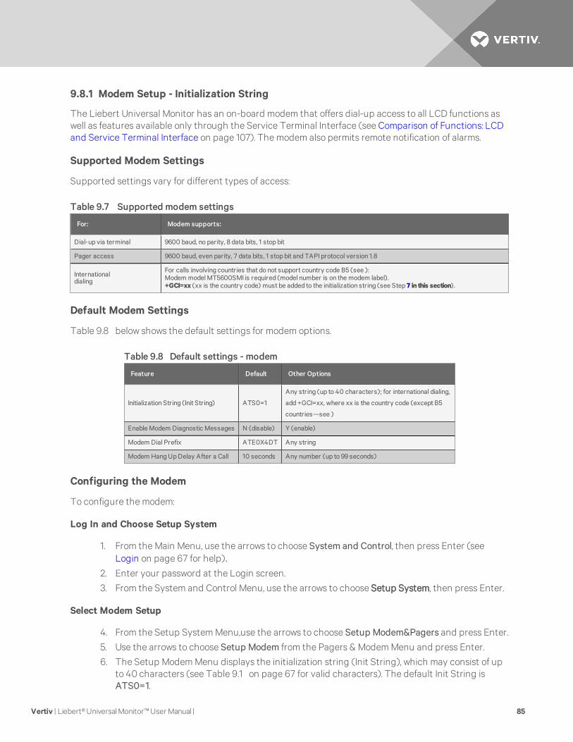
9.8.1 Modem Setup - Initialization String
The Liebert Universal Monitor has an on-board modem that offers dial-up access to all LCD functions aswell as features available only through the Service Terminal Interface (see Comparison of Functions: LCDand Service Terminal Interface on page 107). The modem also permits remote notification of alarms.
Supported Modem Settings
Supported settings vary for different types of access:
For: Modem supports:
Dial-up via terminal 9600 baud, no parity, 8 data bits, 1 stop bit
Pager access 9600 baud, even parity, 7 data bits, 1 stop bit and TAPI protocol version 1.8
Internationaldialing
For calls involving countries that do not support country code B5 (see ):Modem model MT5600SMI is required (model number is on the modem label).+GCI=xx (xx is the country code) must be added to the initialization string (see Step 7 in this section).
Table 9.7 Supported modem settings
Default Modem Settings
Table 9.8 below shows the default settings for modem options.
Feature Default Other Options
Initialization String (Init String) ATS0=1
Any string (up to 40 characters); for international dialing,
add +GCI=xx, where xx is the country code (except B5
countries—see )
Enable Modem Diagnostic Messages N (disable) Y (enable)
Modem Dial Prefix ATE0X4DT Any string
Modem Hang Up Delay After a Call 10 seconds Any number (up to 99 seconds)
Table 9.8 Default settings - modem
Configuring the Modem
To configure the modem:
Log In and Choose Setup System
1. From the Main Menu, use the arrows to choose System and Control, then press Enter (seeLogin on page 67 for help).
2. Enter your password at the Login screen.
3. From the System and Control Menu, use the arrows to choose Setup System, then press Enter.
Select Modem Setup
4. From the Setup System Menu,use the arrows to choose Setup Modem&Pagers and press Enter.
5. Use the arrows to choose Setup Modem from the Pagers & Modem Menu and press Enter.
6. The Setup Modem Menu displays the initialization string (Init String), which may consist of upto 40 characters (see Table 9.1 on page 67 for valid characters). The default Init String isATS0=1.
Vertiv | Liebert® Universal Monitor™ User Manual | 85
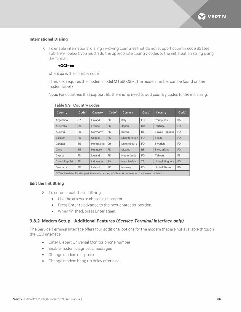
International Dialing
7. To enable international dialing involving countries that do not support country code B5 (seeTable 9.9 below), you must add the appropriate country codes to the initialization string usingthe format:
+GCI=xx
where xx is the country code.
(This also requires the modem model MT5600SMI; the model number can be found on themodem label.)
Note: For countries that support B5, there is no need to add country codes to the init string.
Country Code* Country Code* Country Code* Country Code*
Argentina 07 Finland FD Italy FD Philippines B5
Australia 09 France FD Japan 00 Portugal FD
Austria FD Germany FD Korea B5 Slovak Republic FD
Belgium FD Greece FD Liechtenstein FD Spain FD
Canada B5 Hong Kong 99 Luxembourg FD Sweden FD
China B5 Hungary FD Mexico B5 Switzerland FD
Cyprus FD Iceland FD Netherlands FD Taiwan FE
Czech Republic FD Indonesia 99 New Zealand 7E United Kingdom FD
Denmark FD Ireland FD Norway FD United States B5
* B5 is the default setting—initialization string +GCI=xx is not needed for these countries
Table 9.9 Country codes
Edit the Init String
8. To enter or edit the Init String:
• Use the arrows to choose a character.
• Press Enter to advance to the next character position.
• When finished, press Enter again.
9.8.2 Modem Setup - Additional Features (Service Terminal Interface only)
The Service Terminal Interface offers four additional options for the modem that are not available throughthe LCD interface:
• Enter Liebert Universal Monitor phone number
• Enable modem diagnostic messages
• Change modem dial prefix
• Change modem hang up delay after a call
Vertiv | Liebert® Universal Monitor™ User Manual | 86
To access these options:
• Connect to the Liebert Universal Monitor either from a remote computer or through the RS232port (see Connecting to the Service Terminal Interface on page 109).
• At the Main Menu, enter 0 (zero—Setup System-Login Required).
• At the Login Menu, enter your password.
• At the Setup Menu, enter 6 (Setup Modem&Pagers).
• At the Setup Modem & Pagers menu, enter 5 to begin configuration.
• At the Change Modem Initialization String prompt, you may press Enter to bypass this option(or see Modem Setup - Initialization String on page 85 for instructions on entering the string).
Enter Liebert Universal Monitor Phone Number
This entry allows you to store the phone number that must be dialed to access the Liebert UniversalMonitor for future reference. This has no effect on the Liebert Universal Monitor’s modem settings orfunctionality—it simply places the phone number in an accessible location.
• At the Liebert Universal Monitor Phone Number prompt, enter the phone number for theLiebert Universal Monitor. The current setting appears in brackets [].
• Press Enter to proceed, or Escape to cancel the entry. If you make a change, a confirmationmessage appears: “Command Successful.”
Vertiv | Liebert® Universal Monitor™ User Manual | 87
Enable Modem Diagnostic Messages
Enabling modem diagnostics will provide the following additional information about the modem to thecomputer using the Service Terminal Interface:
Hang-up modem
Modem model number
No dial tone
No carrier
Busy
No answer
Pager checksum error
Pager pin number error
Error (indicates incorrect phone number, dial prefix or modem initialization string)For alphanumeric pager failures:
Paging company non answer on 1st
Paging company non answer on 2nd
Paging company non answer on Last
Paging company non answer on Handshake
• At the Enable Modem Diagnostic Messages prompt, enter Y (Yes - enable) or N (No - disable).The current setting appears in brackets.
• Press Enter to proceed, or Escape to cancel the entry. If you make a change, a confirmationmessage appears: “Command Successful.”
Change Modem Dial Prefix
• At the Change Modem Dial Prefix prompt, enter the prefix to be dialed. The current settingappears in brackets.
• For international dialing involving countries that do not support B5 (see ), add country codesto the initialization string using the format +GCI=xx, where xx is the country code.(Note: Also requires MT5600SMI modem; model number is on modem label.)
See Modem Setup - Initialization String on page 85 for more information.
• Press Enter to proceed, or Escape to cancel the entry. If you make a change, a confirmationmessage appears: “Command Successful.”
Vertiv | Liebert® Universal Monitor™ User Manual | 88
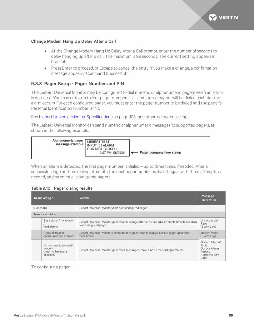
Change Modem Hang Up Delay After a Call
• At the Change Modem Hang Up Delay After a Call prompt, enter the number of seconds todelay hanging up after a call. The maximum is 99 seconds. The current setting appears inbrackets
• Press Enter to proceed, or Escape to cancel the entry. If you make a change, a confirmationmessage appears: “Command Successful.”
9.8.3 Pager Setup - Pager Number and PIN
The Liebert Universal Monitor may be configured to dial numeric or alphanumeric pagers when an alarmis detected. You may enter up to four pager numbers—all configured pagers will be dialed each time analarm occurs. For each configured pager, you must enter the pager number to be dialed and the pager’sPersonal Identification Number (PIN).
See Liebert Universal Monitor Specifications on page 105 for supported pager settings.
The Liebert Universal Monitor can send numeric or alphanumeric messages to supported pagers, asshown in the following example:
When an alarm is detected, the first pager number is dialed—up to three times, if needed. After asuccessful page or three dialing attempts, the next pager number is dialed, again with three attempts asneeded, and so on for all configured pagers.
Result of Page ActionMessageGenerated
Successful Liebert Universal Monitor dials next configured pager. —
Unsuccessful due to:
Busy signal / no answer/no dial tone
Liebert Universal Monitor generates message after all three redial attempts have failed, dialsnext configured pager.
UnsuccessfulPage(Event Log)
General modemcommunication problem
Liebert Universal Monitor resets modem, generates message, redials pager up to threemore times.
Modem Reset(Event Log)
No communication withmodem(internal hardwareproblem)
Liebert Universal Monitor generates messages, makes no further dialing attempts.
Modem InternalFault(Active AlarmReport,Alarm HistoryLog)
Table 9.10 Pager dialing results
To configure a pager:
Vertiv | Liebert® Universal Monitor™ User Manual | 89

Log In and Choose Setup System
• From the Main Menu, use the arrows to choose System and Control, then press Enter (seeLogin on page 67 for help).
• Enter your password at the Login screen.
• From the System and Control Menu, use the arrows to choose Setup System, then press Enter.
Select a Pager to Configure
• From the Setup System Menu, use the arrows to choose Setup Modem&Pagers and pressEnter.
• Use the arrows to choose Setup Pagers from the Pagers & Modem Menu, and press Enter.
• From the Select Pager Menu, choose the pager number you want—for example, Pager Number1—and press Enter.
Enter a Pager Number
• From the Setup Pager Menu, choose Setup Pager Number for the selected pager and pressEnter.
• See Table 9.11 below for guidelines on entering the pager number, which may consist of up to40 characters. To enter the pager number:
• Use the arrows to choose a character.
• Press Enter to advance to the next character position.
• When finished, press Enter again.
Device type Required entries Example
Numericpager The first character must be “N”. N18005551212
Alphanumericpager The first character must be “A”. A18005551212
Remotemodem The first character must be “M”. M18005551212
Device type Optional entries Example
All typesof devices
Use “9” if needed to access an outsideline—place after first character (N, A or M). A918005551212
Use "W" to wait for a second dial tonebefore dialing if the phone system has twodial tones (initial tone and a second tonefor outside line)—place after “9” (before thenumber to be dialed).
A9W18005551212
Use “,” (comma) to pause two seconds. N1,8005551212
Numericpager Use “#” as the last character to terminate page string if required by paging company. N18005551212
,,,,1234567#
Table 9.11 Guidelines for dialing pagers
Vertiv | Liebert® Universal Monitor™ User Manual | 90
Enter a Pager PIN Number
• From the Setup Pager Menu, choose Setup Pager PIN, and press Enter.
• To enter the pager PIN, which may consist of up to 20 characters (see Table 9.1 on page 67 forvalid characters):
• Use the arrows to choose a character.
• Press Enter to advance to the next character position.
• When finished, press Enter again.
NOTE: For international dialing, you might need to add country codes in the modem initialization string.See Modem Setup - Initialization String on page 85.
9.8.4 Pager Setup - Communications Check (Service Terminal Interface only)
The Service Terminal Interface offers two additional options for pager setup, which are not availablethrough the LCD interface:
• Enable communications check
• Enter time to perform communications check
To access these options:
• Connect to the Liebert Universal Monitor either from a remote computer or through the RS232port (see Connecting to the Service Terminal Interface on page 109).
• At the Main Menu, enter 0 (zero—Setup System-Login Required).
• At the Login Menu, enter your password.
• At the Setup Menu, enter 6 (Setup Modem&Pagers).
• At the Setup Modem & Pagers menu, enter a number (1-4) to select a pager.
• At the Enter Pager Number prompt, you may press Enter to bypass this option (or see PagerSetup - Pager Number and PIN on page 89 for instructions on entering the pager number).
• At the Enter Pager PIN Number prompt, you may press Enter to bypass this option (or seePager Setup - Pager Number and PIN on page 89 for instructions on entering the pager PIN).
Enable Communications Check
Enabling this function permits a daily communications test between the Liebert Universal Monitor andthe selected pager. Once each day the Liebert Universal Monitor dials the pager at a specified time andsends this message: “UNIVERSAL MONITOR COMM CHECK.” (The time of the test is specified at the nextprompt, Enter Time To Perform Communications Check on the next page.)
• At the Enable Communications Check prompt, enter Y (Yes - enable) or N (No - disable). Thecurrent setting appears in brackets.
• Press Enter to proceed, or Escape to cancel the entry. If you make a change, a confirmationmessage appears: “Command Successful.”
Vertiv | Liebert® Universal Monitor™ User Manual | 91
Enter Time To Perform Communications Check
This function schedules the daily communications test between the Liebert Universal Monitor and theselected pager, as described in the previous section.
• At the Enter Time To Perform Communications Check prompt, enter the time to initiate thecommunications check, using the format HH:MM (hours and minutes in military time), rangingfrom 00:00 for midnight to 23:59 for 11:59 p.m. The current setting appears in brackets.
• Press Enter to proceed, or Escape to cancel the entry. If you make a change, a confirmationmessage appears: “Command Successful.”
9.9 Setup System - Setup System Info
The Setup System Info options allow users to:
• Change Password—used for access to system setup functions
• Change Date & Time/Automatic Daylight Saving Time—used to set the Liebert UniversalMonitor’s date and time and to enable automatic time change for Daylight Saving Time
• Setup Site ID—the Liebert Universal Monitor’s location to differentiate among sites if morethan one Liebert Universal Monitor is in use
• Connect Battery—stops the Liebert Universal Monitor battery from backing up the panel
• Backup and Upload Configuration File (Service Terminal Interface only)—permits the user tocopy the Liebert Universal Monitor’s configuration settings and to upload the file to the LiebertUniversal Monitor
• Setup Serv Ph Num—enables alarm notification to the telephone number entered (in additionto the four pager numbers).
• Restore Defaults—returns the Liebert Universal Monitor to its factory settings
• Perform Firmware Update (Service Terminal Interface only)—changes the Liebert UniversalMonitor’s firmware to newest version
• Initiate Remote Alarm Test (Service Terminal Interface only)—used to test auxiliary alarm
To change any Setup System Info features:
Log In and Choose Setup System
• From the Main Menu, use the arrows to choose System and Control, then press Enter (seeLogin on page 67 for help).
• Enter your password at the Login screen.
• From the System and Control Menu, use the arrows to choose Setup System, then press Enter.
Select Setup System
• From the Setup System Menu, shown below, use the arrows to choose Setup System Info andpress Enter.
• Use the steps following Figure 9.2 on the facing page to access any of the Setup System Infooptions.
Figure 9.2 on the facing page offers a quick look at the Setup System Info screens available via the LCDinterface.
Vertiv | Liebert® Universal Monitor™ User Manual | 92
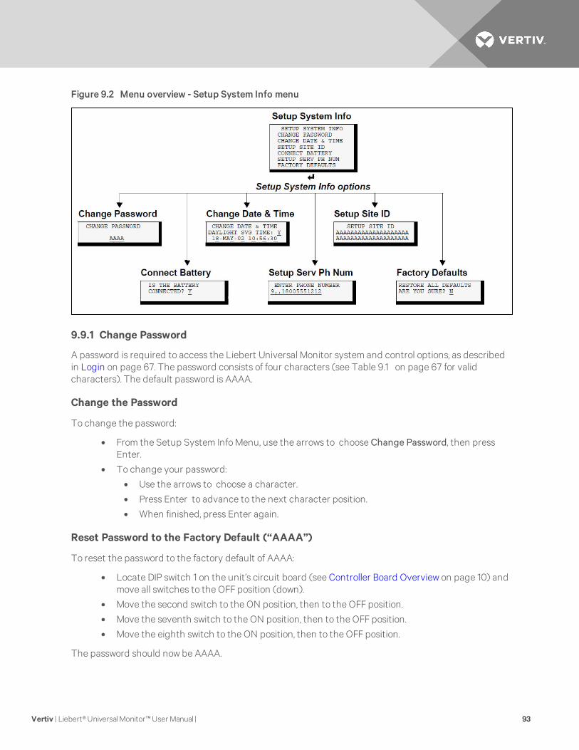
Figure 9.2 Menu overview - Setup System Info menu
9.9.1 Change Password
A password is required to access the Liebert Universal Monitor system and control options, as describedin Login on page 67. The password consists of four characters (see Table 9.1 on page 67 for validcharacters). The default password is AAAA.
Change the Password
To change the password:
• From the Setup System Info Menu, use the arrows to choose Change Password, then pressEnter.
• To change your password:
• Use the arrows to choose a character.
• Press Enter to advance to the next character position.
• When finished, press Enter again.
Reset Password to the Factory Default (“AAAA”)
To reset the password to the factory default of AAAA:
• Locate DIP switch 1 on the unit’s circuit board (see Controller Board Overview on page 10) andmove all switches to the OFF position (down).
• Move the second switch to the ON position, then to the OFF position.
• Move the seventh switch to the ON position, then to the OFF position.
• Move the eighth switch to the ON position, then to the OFF position.
The password should now be AAAA.
Vertiv | Liebert® Universal Monitor™ User Manual | 93
9.9.2 Change Date & Time/Automatic Daylight Saving Time
The Liebert Universal Monitor has a built-in real-time clock that is backed up by an encapsulated lithiumbattery and set up to adjust automatically for daylight saving time twice a year. The Setup System Infomenu allows you to change the date or time or automatic adjustment at any time.
To change the daylight saving time setting, date or time:
• From the Setup System Info Menu, use the arrows to choose Change Date & Time, then pressEnter.
• To change the daylight saving time setting:
• To the right of Daylight Svg Time? use the arrows to choose Y (Yes - automaticallyadjust for daylight saving time) or N (No), then press Enter.
• The format of the date and time is DD-MMM-YY HR:MM:SS. To change the date or time:
• Press Enter to advance to the next character position you want to change.
• Use the arrows to choose from available entries.
• Press Enter to advance to the next character position.
• When finished, press Enter again.
9.9.3 Setup Site ID
You may enter a Site ID to identify the Liebert Universal Monitor’s location, using a name that may consistof up to 40 characters (see 9 on page 67 for valid characters). The Site ID will appear with each alarm.
To enter or change the Site ID:
• From the Setup System Info Menu, use the arrows to choose Setup Site ID, then press Enter.
• To enter a Site ID:
• Use the arrows to choose a character.
• Press Enter to advance to the next character position.
• If the Site ID is less than 40 characters, you may enter an underscore (_) character toindicate the end of the name.
• When finished, press Enter again.
9.9.4 Connect Battery
By default, the Liebert Universal Monitor checks the battery and sounds an alarm when the power fails,the battery runs low or the battery needs to be checked. The battery’s main purpose is to provide enoughpower to the modem to notify pagers of a power loss.
NOTE: The battery will continue to power and provide full operation of the Liebert Universal Monitorwith the exception of powering the analog inputs (sensors). The battery will provide backup for aminimum of 10minutes.
Using the following procedure to disconnect the battery will disable battery alarm features only. Thebattery itself will continue to provide backup. If battery backup is not desired, the battery must beunplugged from the circuit board. This can be done by removing the battery leads from the jumpers (seeConnecting the Battery Pack on page 26).
The default is to connect the battery. However, there may be times that you want to disconnect thebattery so that it does not provide backup.
Table 9.12 on the facing page shows battery problems that will affect operation.
Vertiv | Liebert® Universal Monitor™ User Manual | 94
Result of BatteryMessageGenerated
Battery falls below a minimum charge. Battery will not provide battery backup. LOW BATTERY
Battery is connected to the circuit board but not recognized by thecircuit board. Battery will not provide battery backup. CHECK BATTERY
Battery is unplugged from the circuit board. Battery will not provide battery backup BATTERYUNPLUGGED
Utility power (24VAC) to the circuit board is too low to power theboard.
Liebert Universal Monitor board will not be able tofunction properly. LOSS OF POWER
Table 9.12 Battery alarms
To connect or disconnect the battery:
• From the Setup System Info Menu, use the arrows to choose Connect Battery, then press Enter.
• Use the arrows to choose Y (Yes - the battery is connected) or N (No - the battery is notconnected), then press Enter.
9.9.5 Backup and Upload Configuration File (Service Terminal Interface only)
This operation may be performed only through the Service Terminal Interface. It permits the user to makea copy of the Liebert Universal Monitor configuration settings and save it as a file on the computerconnected through the RS232 port. Should the need arise, the user can upload the configuration file fromthe computer to the Liebert Universal Monitor, instead of re-entering the settings manually.
To access these options:
1. Connect to the Liebert Universal Monitor either from a remote computer or through the RS232port (see Connecting to the Service Terminal Interface on page 109).
2. At the Main Menu, enter 0 (zero—Setup System-Login Required).
3. At the Login Menu, enter your password.
4. At the Setup Menu, enter 7 (Setup System Information).
5. At the Setup System Information Menu, enter 5 (Backup & Upload Configuration File). TheBackup & Upload Configuration File menu appears.
6. Enter 1 to back up the configuration file from the Liebert Universal Monitor to the computerand proceed to Step 8,
OR
7. Enter 2 to upload the configuration file from the computer to the Liebert Universal Monitor andproceed to Step 13. NOTE: This will replace the current configuration settings in the LiebertUniversal Monitor with the most recent backup.
Back Up the Configuration File
8. At the prompt to Initiate a Backup of Configuration File, enter Y (Yes - begin) or N (No -cancel). The current setting appears in brackets.
NOTE: The following instructions refer to the Microsoft Windows HyperTerminal program. Thesesteps may vary for other communications programs.
9. At the top of the HyperTerminal window, click on Transfer, then on Receive File.
Vertiv | Liebert® Universal Monitor™ User Manual | 95
10. In the Receive File window:
• In the Place Received File in the Following Folder box, enter the name and location of thefolder where the configuration file should be placed—for example, C:\downloads—or clickon the Browse button to locate the folder.
• In the Use Receiving Protocol box, select Xmodem from the drop-down list.
• Click on the Receive button. (To close the window without backing up the file, click onClose or Cancel.)
11. In the Receive Filename window, enter a name for the file—for example, UMconfig.sav.
12. When the transfer is complete, a confirmation message appears in the Service TerminalInterface window: “Backup Successful.”
Upload the Configuration File
13. At the prompt to Initiate an Upload of Configuration File, enter Y (Yes - begin) or N (No -cancel). The current setting appears in brackets.
NOTE: The following instructions refer to the Microsoft Windows HyperTerminal program. Thesesteps may vary for other communications programs.
14. At the top of the HyperTerminal window, click on Transfer, then on Send File.
15. In the Send File window:
• In the Filename box, enter the full path of the file to be uploaded—for example,UMconfig.sav—or click on the Browse button to locate the file.
• In the Protocol box, select Xmodem from the drop-down list.
• Click on the Send button. (To close the window without sending the file, click on Close orCancel.)
16. When the transfer is complete, a confirmation message—“Upload Successful”—appears in theService Terminal Interface window and the Liebert Universal Monitor reboots with the newconfiguration.
9.9.6 Setup Serv Ph Num - Enter Phone Number
The Service Phone Number (Serv Ph Num) is used for remote monitoring by Vertiv™ Services. Thenumber is designed to allow remote monitoring services to connect to the Liebert Universal Monitor. Allalarms will be sent to this number. When an alarm occurs, this number is dialed before any of the fourpager numbers.
To use the service phone number features, be sure to connect the phone line connector to a telephonewall jack using an RJ11 cord, as described in Phone Line Connector on page 42.
Vertiv | Liebert® Universal Monitor™ User Manual | 96
Result ofDialing ActionMessageGenerated
Successful — —
Unsuccessful due to:
Busy signal / no answer /no dial tone
Liebert Universal Monitor generates message after all threeredial attempts have failed, dials next configured pager.
Unsuccessful Page(Event Log)
General modemcommunication problem
Liebert Universal Monitor resets modem, generatesmessage, redials up to three more times.
Modem Reset(Event Log)
No communication withmodem
(internal hardware problem)
Liebert Universal Monitor generates messages,makes no further dialingattempts.
Modem Internal Fault(Active Alarm Report,Alarm History Log)
Table 9.13 Service phone number dialing results
To set up the service phone number:
• From the Setup System Info Menu, use the arrows to choose Setup Serv Ph Num, then pressEnter.
• See Table 9.14 below for guidelines on entering the phone number, which may consist of up to40 characters. To enter the phone number:
• Use the arrows to choose a character.
• Press Enter to advance to the next character position.
• When finished, press Enter again.
Devicetype
Required entries Example
Remotemodem The first character must be “M”. M
18005551212
Devicetype Optional entries Example
All typesofdevices
Use “9” if needed to access an outside line—place after first character (M). M918005551212
Use "W" to wait for a second dial tone before dialing if the phone system has two dial tones (initial tone and a second tonefor outside line)—place after “9” (before the number to be dialed).
M9W18005551212
Use “,” (comma) to pause two seconds. M1,8005551212
Table 9.14 Guidelines for dialing service phone number
Vertiv | Liebert® Universal Monitor™ User Manual | 97
9.9.7 Setup Serv Ph Num - Communications Check (Service Terminal Interface only)
The Service Terminal Interface offers two additional options for setting up the Service Phone Number(Serv Ph Num) that are not available through the LCD interface:
• Enable communications check• Enter time to perform communications check
To access these options:• Connect to the Liebert Universal Monitor either from a remote computer or through the RS232
port (see Connecting to the Service Terminal Interface on page 109).• At the Main Menu, enter 0 (zero—Setup System-Login Required).• At the Login Menu, enter your password.• At the Setup Menu, enter 7 (Setup System Information).• At the Setup System Information Menu, enter 6 (Setup Service Phone Number).• At the Setup Service Phone Number menu, enter 1 to begin the setup.• At the Enter Service Phone Number prompt, you may press Enter to bypass this option (or see
Setup Serv Ph Num - Enter Phone Number on page 96 for instructions on entering thenumber).
Enable Communications CheckEnabling this function permits a daily communications test between the Liebert Universal Monitor andthe selected service phone number. Once each day the Liebert Universal Monitor dials the service phonenumber at a specified time and sends this message: “UNIVERSAL MONITOR COMM CHECK.” (The time ofthe test is specified at the next prompt, Enter Time To Perform Communications Check on page 92.)
• At the Enable Communications Check prompt, enter Y (Yes - enable) or N (No - disable). Thecurrent setting appears in brackets.
• Press Enter to proceed, or Escape to cancel the entry. If you make a change, a confirmationmessage appears: “Command Successful.”
Enter Time To Perform Communications CheckThis function schedules the daily communications test between the Liebert Universal Monitor and theselected service phone number, as described in the previous section.
• At the Enter Time To Perform Communications Check prompt, enter the time to initiate thecommunications check, using the format HH:MM (hours and minutes in military time), rangingfrom 00:00 for midnight to 23:59 for 11:59 p.m. The current setting appears in brackets.
• Press Enter to proceed, or Escape to cancel the entry. If you make a change, a confirmationmessage appears: “Command Successful.”
9.9.8 Factory Defaults
At any time, you may restore all default values for settings in the Liebert Universal Monitor as it wasshipped.
NOTE: This action will overwrite any configuration settings. You maywant to back up your settingsbefore restoring the factory defaults. See Backup and Upload Configuration File (Service TerminalInterface only) in Setup System Info for details on backing up settings using the Service TerminalInterface.
The password is the sole exception when reverting to the factory default settings. The password can bereset to the factory default of AAAA only through the DIP switches. For details, see Change Password onpage 93.
Vertiv | Liebert® Universal Monitor™ User Manual | 98
9.9.9 Perform Firmware Update (Service Terminal Interface only)
This function, which may be performed only through the Service Terminal Interface, upgrades the LiebertUniversal Monitor’s firmware to the newest version.
NOTE: This action will overwrite any configuration settings. You maywant to back up your settingsbefore restoring the factory defaults. See Backup and Upload Configuration File (Service TerminalInterface only) in Setup System Info for details on backing up settings using the Service TerminalInterface.
• Connect to the Liebert Universal Monitor either from a remote computer or through the RS232port (see Connecting to the Service Terminal Interface on page 109).
• At the Main Menu, enter 0 (zero—Setup System-Login Required).
• At the Login Menu, enter your password.
• At the Setup Menu, enter 7 (Setup System Information).
• At the Setup System Info menu, enter 8 (Perform Firmware Update).
• At the Perform Firmware Update menu, enter 1 to proceed with an update.
To perform the update:
1. At the Perform Firmware Update prompt, enter Y (Yes - begin) or N (No - cancel). The currentsetting appears in brackets.
NOTE: The following instructions refer to the Microsoft Windows HyperTerminal program. Thesesteps may vary for other communications programs.
2. The firmware update is a two-step process—this step describes how to upload the fileprog###.s19 (where ### is a number—for example, prog118.s19) to the Liebert UniversalMonitor:
a. At the top of the HyperTerminal window, click on Transfer, then on Send File.
b. In the Send File window:
In the Filename box, enter the full path of the file to be uploaded—prog###.s19—or clickon the Browse button to locate the file.
In the Protocol box, select Xmodem from the drop-down list.
Click on the Send button. (To close the window without sending the file, click on Close orCancel.)
When the transfer is complete, a confirmation message appears in the Service TerminalInterface window.
Vertiv | Liebert® Universal Monitor™ User Manual | 99
3. Next, follow these steps to upload the file flash###.s19 (where ### is a number—for example,flash607.s19) to the Liebert Universal Monitor:
a. At the top of the HyperTerminal window, click on Transfer, then on Send File.
b. In the Send File window:
In the Filename box, enter the full path of the file to be uploaded—flash###.s19—or clickon the Browse button to locate the file.
In the Protocol box, select Xmodem from the drop-down list.
Click on the Send button. (To close the window without sending the file, click on Close orCancel.)
When the transfer is complete, a confirmation message—“Firmware Update Successful”—appears in the Service Terminal Interface window and the Liebert Universal Monitorreboots with the new firmware update.
9.9.10 Initiate Remote Alarm Test (Service Terminal Interface only)
The service phone number is used for remote monitoring by Vertiv™ Services. The Service TerminalInterface may be used to test communications between the Liebert Universal Monitor and the servicemodem. This test will send a “DIAL OUT TEST PASSED” message to the service phone number.
The test is used to simulate an alarm to verify the proper configuration and functioning of the modem andother communications required for receiving alarms. This simulated alarm bypasses the normal alarmsequence—the LCD will not flash, the horn will not sound and there will be no record in the Alarm Log. Amessage is sent to the service phone number only if the alarm system is set up correctly.
To initiate the remote alarm test:
• Connect to the Liebert Universal Monitor either from a remote computer or through the RS232port (see Connecting to the Service Terminal Interface on page 109).
• At the Main Menu, enter 0 (zero—Setup System-Login Required).• At the Login Menu, enter your password.• At the Setup Menu, enter 7 (Setup System Information).• At the Setup System Info menu, enter 9 (Initiate Remote Alarm Test).• At the Initiate Remote Alarm Test menu, enter 1 to initiate the remote alarm.• At the Simulate An Alarm Condition prompt, enter Y if you wish to proceed or N if you want to
cancel the alarm simulation.• After the “Command Successful” message appears, disconnect from the modem—at the top of
the HyperTerminal window, click on Call, then on Disconnect.• Wait for the Liebert Universal Monitor to dial out to send a test message.• To verify whether the test was successful, check the Event Log (see View Event Log on
page 59) for one of these two messages: Dial out test passed or Dial out test failed.
NOTE: Also verify that a message was received at the Service Phone Number.
If the test is NOT successful, check the following:
• Modem configuration (see Modem Setup - Initialization String on page 85)• Pager configuration (see Pager Setup - Pager Number and PIN on page 89)
Vertiv | Liebert® Universal Monitor™ User Manual | 100
9.10 Setup Exp Board - Optional Expansion Board
By default, the optional Expansion Board is configured as Not connected (N). After connecting power tothe board and connecting it to the Liebert Universal Monitor, you must specify the Expansion Board asConnected (Y), as described in this section.
NOTE: Before specifying the Expansion Board as Connected, be sure to connect power to the boardand connect it to the Liebert Universal Monitor. For more information, see:Input Power Connections - Optional Expansion Board on page 30Connect EIA485 Connectors to Main Board on page 48
To change the Expansion Board connection setting:
Log In and Choose Setup System
• From the Main Menu, use the arrows to choose System and Control, then press Enter.• Enter your password at the Login screen.
• From the System and Control Menu, use the arrows to choose Setup System, then press Enter.
Identify the Expansion Board as Connected (Y) or Not Connected (N)
• From the Setup System Menu, use the arrows to choose Setup Exp Board and press Enter.
• To change this setting, use the arrows to choose Y (Yes - Connected) or N (No - Notconnected), then press Enter.
9.11 Manual Output Ctrl
The Manual Output Ctrl feature allows you to manually change the state of any digital output to ON orOFF, overriding automatic control by the Liebert Universal Monitor (the default setting for all outputs).This menu also allows you to release the manual override, returning any output to automatic control.There are two ways to override automatic control of outputs:
• Use the Manual Output Ctrl menu, as described in this section, to turn any output ON or OFF.
• Use the switch on the Liebert Universal Monitor board (see Controller Board Overview onpage 10) to force all eight outputs ON at the same time. (Note: This has no effect on theoptional Expansion Board outputs.)
After an output is forced manually ON or OFF through the Manual Output Ctrl menu, it remains in thatstate until returned to automatic control through this menu.Table 9.15 below summarizes the four types of control, including the abbreviated message that appearson the LCD and in log reports.
Message Description
AUTO Automatic Controlled by Liebert Universal Monitor
MAN ON Manually ON This output forced ON or OFFvia Manual Output Ctrl menuMAN OFF Manually OFF
HW MAN ON Manually ON(all outputs)
All outputs forced ONvia hardware switch on circuit board
Table 9.15 Automatic / manual control - outputpoints
To force an output point ON or OFF or return it to automatic control:
Vertiv | Liebert® Universal Monitor™ User Manual | 101
Log In and Choose Manual Output Ctrl
• From the Main Menu, use the arrows to choose System and Control, then press Enter (seeLogin on page 67 for help).
• Enter your password at the Login screen.
• From the System and Control Menu, use the arrows to choose Manual Output Ctrl, then pressEnter.
Select an Output
The Select Output menu, shown below, display the current status of all eight outputs.
• Use the arrows to choose the output you want—for example, Output01—and press Enter.
Turn Output ON or OFF / Return to Automatic
• From the Override Output menu, use the arrows to choose one of these options:
• Auto (return to automatic control)
• Man ON (manually turn this output ON)
• Man OFF (manually turn this output OFF)
• Press Enter.
9.12 Clear Alarms & Logs
The Clear Alarms & Logs menu allows you to clear active alarms or delete all records from any of theLiebert Universal Monitor three logs: alarm, event and trend logs.
To clear alarms or logs:
Log In and Choose Clear Alarms & Logs
• From the Main Menu, use the arrows to choose System and Control, then press Enter (seeLogin on page 67 for help).
• Enter your password at the Login screen.
• From the System and Control Menu, use the arrows to choose Clear Alarms & Logs, then pressEnter.
• Use the following steps to clear alarms or delete log records.
9.12.1 Clear Active Alarms
To clear all active alarms:
• From the Clear Alarms/Logs Menu, use the arrows to choose Clear Active Alarms, then pressEnter.
• Use the arrows to choose Y (Yes - clear all active alarms) or N (No - do not clear alarms), thenpress Enter.
Clearing active alarms is the only means to reset latched alarms. This step is required to return latchedpoints to their normal state. To set up a digital input or an analog sensor input as latched, see:
• Set Up Alarmable Inputs in Latched or Unlatched Mode on page 72
• Set Up Alarmable Sensors in Latched or Unlatched Mode on page 78
Vertiv | Liebert® Universal Monitor™ User Manual | 102
9.12.2 Clear the Alarm Log
The alarm log contains up to 99 records of alarms that have occurred. You may want to clear the log afterbacking up the file or simply to free up space.
NOTE: Before deleting the records in the alarm log, you maywant to back up the file to a remotecomputer using the Service Terminal Interface, as described in Back Up Log Files (Service TerminalInterface only) on page 65.
To delete all records from the alarm log:
• From the Clear Alarms/Logs Menu, use the arrows to choose Clear Alarm Log, then press Enter.
• Use the arrows to choose Y (Yes - clear the alarm log) or N (No - do not clear the alarm log),then press Enter.
NOTE: Clear active alarms is the onlymeans to reset Latched alarms. This action must be taken toreturn Latched points to their normal state.
9.12.3 Clear the Event Log
The event log contains up to 99 records of events detected by the Liebert Universal Monitor. You maywant to clear the log after backing up the file or simply to free up space.
NOTE: Before deleting the records in the event log, you maywant to back up the file to a remotecomputer using the Service Terminal Interface, as described in Back Up Log Files (Service TerminalInterface only) on page 65.
To delete all records from the event log:
• From the Clear Alarms/Logs Menu, use the arrows to choose Clear Event Log, then press Enter.
• Use the arrows to choose Y (Yes - clear the event log) or N (No - do not clear the event log),then press Enter.
9.12.4 Clear the Trend Logs
The Liebert Universal Monitor maintains a separate trend log for each configured analog input sensor.Each log contains up to 100 records of data collected at regular intervals. You may want to clear the logsafter backing up the files or simply to free up space.
Using the Clear Trend Logs command will clear all four trend logs maintained by the Liebert UniversalMonitor. There is no method of clearing records from individual logs.
NOTE: Before deleting the records in the trend logs, you maywant to back up the files to a remotecomputer using the Service Terminal Interface, as described in Back Up Log Files (Service TerminalInterface only) on page 65.
To delete the records from ALL four trend logs:
• From the Clear Alarms/Logs Menu, use the arrows to choose Clear Trend Logs, then pressEnter.
• Use the arrows to choose Y (Yes - clear all trend logs) or N (No - do not clear the trend logs),then press Enter.
Vertiv | Liebert® Universal Monitor™ User Manual | 103

Vertiv | Liebert® Universal Monitor™ User Manual | 104
This page intentionally left blank.
10 SPECIFICATIONS
10.1 Liebert Universal Monitor Specifications
NOTE: If the equipment is used in a manner not specified by the manufacturer, the protection providedby the equipment may be impaired.
PowerRequirements
Small Enclosure Large Enclosure
UMS02400 115VAC UML11500 230VAC UML23000
24VAC ±10%
of nominal;
50/60 Hz, 1.3A,
30VA
115VAC ±10%
of nominal;
60Hz, 4A,
460VA
230VAC ±10%
of nominal;
50Hz, 0.5A,
115VA
Dimensions W x D x H, in. (mm)14-1/4 x 2-3/4 x 12
(361.95 x 69.85 x 304.8)
18 x 2-3/4 x 18
(457.2 x 69.85 x 457.2)
Weight (Assembled) 7.68 lb. (3.48 kg) 20.56 lb. (9.33 kg)
Enclosure Type NEMA 1
Liquid Crystal Display (LCD) Four line, 20 character, backlit
Mounting Surface Building Wall or Structural Member
Ambient Operating Environment32ºF to 104ºF (0ºC to 40ºC)
0% RH to 95% RH (non-condensing)
Processor Specifics
Model Motorola XC68HC812A4
Clock speed 16MHz
Total RAM 256Kb
Total FLASH 4M
Total EEPROM 4K
A/D Resolution (Analog IN) 12 Bit
Modem Type Embedded 14.4K bps
Clock Type Real-Time Clock
Clock battery backup type Lithium Cell (non-replaceable)
Clock battery life 7 years, constant, no power
Modem battery backup type Nickel Cadmium (replaceable)
Modem battery life 10 minutes at full load
Communications
Local Communications RS232
Remote Communications
Modem (9600-N-8-1)
Supported pagers
Baud rate 9600 bps, Parity=None, Data bits=8, Stop bits=1
9600 E-7-1 supports TAPI protocol version 1.8
Liebert SiteScan® Web IGM Protocol, EIA422
Expansion Board (optional) EIA485
Agency ListingsNo Transformer Module With Transformer Module
(UMS02400) 115VAC (TM115) 230VAC (TM230)
UL UL3121 UL1012 UL1585
Vertiv | Liebert® Universal Monitor™ User Manual | 105
CE Yes Yes
FCC Compliance CFR 47 Part 15 N/A
Inputs & Outputs (Quantity)
Digital Inputs (8) Dry Contact Closure 24VDC, 10 mA
Analog Inputs (4)4-20 mA signal input with selectable
power source of 12VDC or 24VDC
Digital Outputs (8) 24VAC, 3A
Common Alarm Outputs (2) 24VAC, 3A
10.2 Optional Expansion Board Specifications
NOTE: If the equipment is used in a manner not specified by the manufacturer, the protection providedby the equipment may be impaired.
PowerRequirements
UMEXP
24VAC ±10% of nominal;
50/60 Hz, 0.6A, 15VA Class 2
DimensionsW x D x H, in. (mm)
14-1/4 x 2-3/4 x 12
(361.95 x 69.85 x 304.8)
Weight (Assembled) 7.68 lb. (3.48 kg)
Enclosure Type NEMA 1
Mounting Surface Building Wall or Structural Member
Ambient OperatingEnvironment
32ºF to 104ºF (0ºC to 40ºC)
0% RH to 95% RH (non-condensing)
Inputs & Outputs (Quantity)
Digital Inputs (16) Dry Contact Closure24VDC, 10 mA
Digital Outputs (8) 240VAC, 2A
Vertiv | Liebert® Universal Monitor™ User Manual | 106

APPENDICES
Appendix A: Service Terminal Interface
The Service Terminal Interface allows access to all functions of the Liebert Universal Monitor, includingsome that are not possible through the LCD interface. This interface is accessible through any computerusing a communications program such as Microsoft® Windows® HyperTerminal.This appendix provides directions for connecting to the Service Terminal Interface, an overview of eachtype of function and sample screens for each menu available through the Service Terminal Interface.References to more detailed instructions about each function are provided.
A.1 Comparison of Functions: LCD and Service Terminal Interface
Table A.1 below lists all functions for viewing and configuring the Universal Monitor and shows whetherthey can be performed through the LCD interface and where to find information.
Function
Canbe performedvia:
Where to find:
LCDServiceTerminal
Instructions onusing function
Service Terminalscreen examples
VIEW STATUS FUNCTIONS
View Active Alarms x x View Active Alarms on page 56 View Active Alarms
View Alarm Log x x View Alarm Log on page 57 View Alarm Log
View Event Log x x View Event Log on page 59 View Event Log
View Trend Log x x View Trend Log on page 60 View Trend Log
View Input Status x x View Input Status on page 62 View Input Status
View Output Status x x View Output Status on page 63 View Output Status
View Pager Numbers x x View Pager Numbers on page 63 View Pager Numbers
SILENCE ALARM & BACK UP LOGS FUNCTIONS
Silence Alarm (On the LCD, pressany key to silence an alarm) x x Silence Alarm (Service Terminal Interface) on
page 65Silence Alarm (Service TerminalInterface only)
Back Up Log Files — x Back Up Log Files (Service Terminal Interfaceonly) on page 65
Back Up Log Files (Service TerminalInterface only)
SYSTEM & CONTROL FUNCTIONS
Login x x Login on page 67 Login Menu
Setup System x x Setup System - Overview on page 70 Setup Menu
Setup Input x x Setup System - Setup Input on page 70 Setup Input
Setup Common Alarm x x Setup System - Setup Common Alarm onpage 73 Setup Common Alarm
Setup Sensor x x Setup System - Setup Sensor on page 74 Setup Sensor
Setup I/O Matrix x x Setup System - Setup I/O Matrix on page 80 Setup I/O Matrix
Setup Output x x Setup System - Setup Output on page 83 Setup Output
Pager Setup - Pager Number &PIN x x Pager Setup - Pager Number and PIN on
page 89 Pager Setup
Table A.1 Guide to Universal Monitor functions
Vertiv | Liebert® Universal Monitor™ User Manual | 107
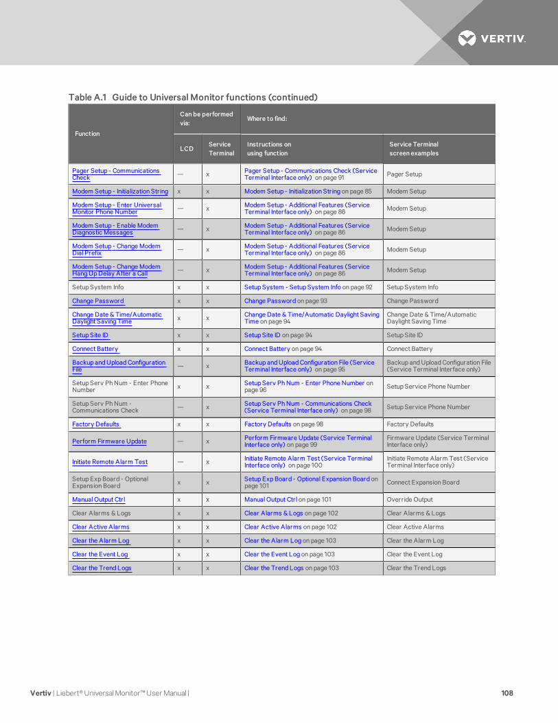
Function
Canbe performedvia:
Where to find:
LCDServiceTerminal
Instructions onusing function
Service Terminalscreen examples
Pager Setup - CommunicationsCheck — x Pager Setup - Communications Check (Service
Terminal Interface only) on page 91 Pager Setup
Modem Setup - Initialization String x x Modem Setup - Initialization String on page 85 Modem Setup
Modem Setup - Enter UniversalMonitor Phone Number — x Modem Setup - Additional Features (Service
Terminal Interface only) on page 86 Modem Setup
Modem Setup - Enable ModemDiagnostic Messages — x Modem Setup - Additional Features (Service
Terminal Interface only) on page 86 Modem Setup
Modem Setup - Change ModemDial Prefix — x Modem Setup - Additional Features (Service
Terminal Interface only) on page 86 Modem Setup
Modem Setup - Change ModemHang Up Delay After a Call — x Modem Setup - Additional Features (Service
Terminal Interface only) on page 86 Modem Setup
Setup System Info x x Setup System - Setup System Info on page 92 Setup System Info
Change Password x x Change Password on page 93 Change Password
Change Date & Time/AutomaticDaylight Saving Time x x Change Date & Time/Automatic Daylight Saving
Time on page 94Change Date & Time/AutomaticDaylight Saving Time
Setup Site ID x x Setup Site ID on page 94 Setup Site ID
Connect Battery x x Connect Battery on page 94 Connect Battery
Backup and Upload ConfigurationFile — x Backup and Upload Configuration File (Service
Terminal Interface only) on page 95Backup and Upload Configuration File(Service Terminal Interface only)
Setup Serv Ph Num - Enter PhoneNumber x x Setup Serv Ph Num - Enter Phone Number on
page 96 Setup Service Phone Number
Setup Serv Ph Num -Communications Check — x Setup Serv Ph Num - Communications Check
(Service Terminal Interface only) on page 98 Setup Service Phone Number
Factory Defaults x x Factory Defaults on page 98 Factory Defaults
Perform Firmware Update — x Perform Firmware Update (Service TerminalInterface only) on page 99
Firmware Update (Service TerminalInterface only)
Initiate Remote Alarm Test — x Initiate Remote Alarm Test (Service TerminalInterface only) on page 100
Initiate Remote Alarm Test (ServiceTerminal Interface only)
Setup Exp Board - OptionalExpansion Board x x Setup Exp Board - Optional Expansion Board on
page 101 Connect Expansion Board
Manual Output Ctrl x x Manual Output Ctrl on page 101 Override Output
Clear Alarms & Logs x x Clear Alarms & Logs on page 102 Clear Alarms & Logs
Clear Active Alarms x x Clear Active Alarms on page 102 Clear Active Alarms
Clear the Alarm Log x x Clear the Alarm Log on page 103 Clear the Alarm Log
Clear the Event Log x x Clear the Event Log on page 103 Clear the Event Log
Clear the Trend Logs x x Clear the Trend Logs on page 103 Clear the Trend Logs
Table A.1 Guide to Universal Monitor functions (continued)
Vertiv | Liebert® Universal Monitor™ User Manual | 108
A.2 Connecting to the Service Terminal Interface
This section describes how to set up and connect to the Service Terminal Interface.
Connection Methods
There are two ways to access the Service Terminal Interface:
• Direct—Use a null modem cable to connect a computer’s COM1 port to the Universal Monitor’sRS232 port,
OR
• Remote—Use a remote computer’s modem to dial the telephone number of the phone lineconnected to the Universal Monitor.
Both methods require a communications program, such as HyperTerminal, to connect to the ServiceTerminal Interface.
Refer to Table A.2 below for step-by-step instructions to set up each type of connection. Note that theremote connection does not require setting up the COM1 port.
Direct Remote
Create a Connection below 4 4
Set Up the COM1 Port - Direct Connection Only 4 N/A
Set Up the Connection’s Properties 4 4
Connect to the Service Terminal Interface 4 4
Table A.2 Steps to set up a direct or remote connection
The instructions in this section refer to the HyperTerminal program—they may vary for othercommunications programs.
Create a Connection
Before connecting to the Service Terminal Interface, you must create a connection and specify themethod to be used for connection, as described in the following steps.
1. Start the HyperTerminal program—to do this, click on the Start button, then on Programs,then Accessories, then Communications, and finally HyperTerminal.
2. At the top of the HyperTerminal window, click on File, then on New Connection.3. In the Connection Description window, enter a name for the connection—for example,
Universal Monitor. This becomes the file name (with the extension “.ht”).4. Click OK to close the window. The Connect To window opens.
Vertiv | Liebert® Universal Monitor™ User Manual | 109
5. In the Connect To window, select the appropriate connection method from the Connect Usingdrop-down list:
Direct Connection via RS232
• To set up a direct connection via the Universal Monitor’s RS232 port, select COM1 asshown above left.
• This opens the COM1 Properties window. Proceed to Step 6 (next section).
Remote Connection via Modem
• To make a remote connection through the Universal Monitor’s modem, select yourcomputer’s modem—HSP56 MicroModem in the example shown above right.
• Enter the area code and phone number of the Universal Monitor’s modem.
• Proceed to Step 8 in Set Up the Connection’s Properties (skip Steps 6 and 7).
Set Up the COM1 Port - Direct Connection Only
The following steps apply only to setting up a direct connection to the Service Terminal Interface via theUniversal Monitor’s RS232 port. If you are setting up a remote connection via modem, skip to Step 8 (nextsection).
COM1 Port Setup
6. In the COM1 Properties window, make the following selections:
• Bits per second: 9600• Data bits: 8• Parity: None• Stop bits: 1• Flow control: None
7. Click OK. When the connection is open, the connection name appears in the title bar of theHyperTerminal window. To complete the setup, continue with Step 8 (next section).
Set Up the Connection’s Properties
The following steps are needed for both direct and remote connection to the Universal Monitor.
Properties Setup
8. Open the Properties window by clicking on File, then on Properties.
9. In the Properties window, click on the Settings tab and choose the following settings:
• Function, arrow, and ctrl keys act as: Terminal keys• Backspace key sends: Ctrl+H• Emulation: ANSIW• Telnet terminal ID: VT100• Backscroll buffer lines: 500• Play sound when connecting or disconnecting: Unchecked
Vertiv | Liebert® Universal Monitor™ User Manual | 110
ASCII Setup
10. In the Properties window, click on the ASCII Setup button.
11. In the ASCII Setup window, choose the following settings:
• ASCII Sending: place a check mark in the Send Line Ends With Line Feeds box.
• ASCII Receiving: place a check mark in the Wrap Lines That Exceed Terminal Width box.
• Click OK.
The setup is now complete. To use the new connection, proceed to the next section, Connect to theService Terminal Interface below.
Connect to the Service Terminal Interface
After creating and setting up a connection, use a communications program such as HyperTerminal toaccess the Universal Monitor’s Service Terminal Interface.
1. Verify communications connections between the remote computer and the Universal Monitor:
a. For direct connection (via RS232 port): Connect a null modem cable from the computer’sCOM1 port to the Universal Monitor’s RS232 port (for location, see RS232 Connector onpage 42).
b. For remote connection (via modem): Verify modem connections between the remotecomputer and the Universal Monitor. The remote computer should have connectivitythrough a telephone line, high-speed cable or an Ethernet. The Universal Monitor musthave a telephone line connected to its RJ11 port (for location, see Phone Line Connectoron page 42).
2. Start the HyperTerminal program—click on the Start button, then on Programs, thenAccessories, then Communications, and finally HyperTerminal.
3. Open the Universal Monitor connection created in Create a Connection on page 109. To dothis, click on File, then on Open.
4. In the Open window, select the file name and then click on the Open button.
5. Follow the steps below to display the Main Menu of the Service Terminal Interface:
a. For direct connection (via RS232 port): Press Enter (or Escape) to initiate communicationand bring up the Main Menu.
b. For remote connection (via modem):
The Connect window opens. Click the OK button.
In the Connect window, click Dial.
If the dialing attempt is successful, the Main Menu appears.
For more information on the Universal Monitor’s options:
• See Overview of Menus on the next page for examples of the Service Terminal Interfacescreens.
• See Table A.1 on page 107 to locate step-by-step instructions for each Universal Monitorfunction.
Vertiv | Liebert® Universal Monitor™ User Manual | 111
A.3 Overview of Menus
The Main Menu offers choices for viewing the status of the Universal Monitor, silencing the audible alarmand backing up the unit’s log files. It also allows access to the System and Control features, which require apassword.
View Status Overview
The View Status features are available to all users. This permits all personnel to check on the status of anyequipment or location being monitored. These options allow any user to:
• View current monitoring data—active alarms and the status of all inputs and outputs
• View data stored in alarm, event and trend logs
• View pager numbers
Silence Alarm and Backup Log Files
Two Main Menu options—Silence Alarm and Backup Log Files—are unique to the Service TerminalInterface. As with the View Status options, these features do not require a password:
• Silence Alarm—silence the Universal Monitor’s audible alarm and reset the Common AlarmRelay output.
• Backup Log Files—make backup copies of the Universal Monitor’s Alarm Log, Event Log andTrend Logs and save the copies to a computer.
Setup Menu Overview
The Setup Menu options require a password. Authorized users may:
• Configure the Universal Monitor—this includes setting up digital and analog inputs, digitaloutputs, the modem, up to four pagers, and system features such as setting the date and time
Three system features—Backup and Upload Configuration File, Firmware Update and InitiateRemote Alarm Test—are unique to the Service Terminal Interface.
• Override automatic control of outputs to force an output ON or OFF
• Clear active alarms and delete all records in the alarm, event and trend logs
A.4 View Status Menus
The View Status menu allows any user to view currently active alarms, monitoring data stored in thealarm, event and trend logs, the status of all inputs and outputs, and the four pager numbers.
Main Menu
After connecting to the Service Terminal Interface, the Main Menu appears
View Active Alarms
For details on this feature, see View Active Alarms on page 56.
View Alarm Log
For details on this feature, see View Alarm Log on page 57.
Vertiv | Liebert® Universal Monitor™ User Manual | 112
View Event Log
For details on this feature, see View Event Log on page 59.
View Trend Log
For details on this feature, see View Trend Log on page 60.
View Input Status
For details on this feature, see View Input Status on page 62.
View Output Status
For details on this feature, see View Output Status on page 63.
View Pager Numbers
For details on this feature, see View Pager Numbers on page 63.
A.5 Silence Alarm & Back Up Log Files (Service Terminal Interface only)
This section presents two options from the Main Menu that are available via the Service TerminalInterface only.
Main Menu
After connecting to the Service Terminal Interface, the Main Menu appears.
Silence Alarm (Service Terminal Interface only)
For details on this feature, see Silence Alarm (Service Terminal Interface) on page 65.
Back Up Log Files (Service Terminal Interface only)
For details on this feature, see Back Up Log Files (Service Terminal Interface only) on page 65.
A.6 Setup Menu
The Setup menu allows the user to configure the Universal Monitor—setting up inputs and outputs andan input/output matrix to trigger actions, the modem and pagers, and system features such as date andtime. This menu also provides a vehicle for manually changing the state of an output to ON or OFF,clearing active alarms and deleting records from the Universal Monitor’s alarm log, event log and trendlogs.
Main Menu
After connecting to the Service Terminal Interface, the Main Menu.
• Choose 0 to access the features illustrated in this section.
Vertiv | Liebert® Universal Monitor™ User Manual | 113
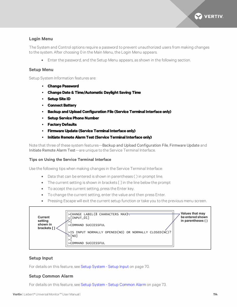
Login Menu
The System and Control options require a password to prevent unauthorized users from making changesto the system. After choosing 0 in the Main Menu, the Login Menu appears.
• Enter the password, and the Setup Menu appears, as shown in the following section.
Setup Menu
Setup System Information features are:
• Change Password
• ChangeDate &Time/Automatic Daylight Saving Time
• Setup Site ID
• Connect Battery
• Backup and Upload Configuration File (Service Terminal Interface only)
• Setup Service PhoneNumber
• FactoryDefaults
• Firmware Update (Service Terminal Interface only)
• Initiate RemoteAlarmTest (Service Terminal Interface only)
Note that three of these system features—Backup and Upload Configuration File, Firmware Update andInitiate Remote Alarm Test—are unique to the Service Terminal Interface.
Tips on Using the Service Terminal Interface
Use the following tips when making changes in the Service Terminal Interface:
• Data that can be entered is shown in parentheses ( ) in prompt line.
• The current setting is shown in brackets [ ] in the line below the prompt
• To accept the current setting, press the Enter key.
• To change the current setting, enter the value and then press Enter.
• Pressing Escape will exit the current setup function or take you to the previous menu screen.
Setup Input
For details on this feature, see Setup System - Setup Input on page 70.
Setup Common Alarm
For details on this feature, see Setup System - Setup Common Alarm on page 73.
Vertiv | Liebert® Universal Monitor™ User Manual | 114
Setup Sensor
For details on this feature, see Setup System - Setup Sensor on page 74.
Setup I/O Matrix
For details on this feature, see Setup System - Setup I/O Matrix on page 80.
Setup Output
For details on this feature, see Setup System - Setup Output on page 83.
Setup Modem & Pagers
For details on this topic, see Setup System - Setup Modem & Pagers on page 84.
Pager Setup
For details on this feature, see Pager Setup - Pager Number and PIN on page 89 and Pager Setup -Communications Check (Service Terminal Interface only) on page 91.
Modem Setup
For details on this feature, see Modem Setup - Initialization String on page 85 and Modem Setup -Additional Features (Service Terminal Interface only) on page 86.
Setup System Info
This section presents Service Terminal Interface screens for choices 1 through 9 in the Setup SystemInformation menu shown below. For details on this topic, see Setup System - Setup System Info onpage 92.
Change Password
For details on this feature, see Change Password on page 93.
Change Date & Time/Automatic Daylight Saving Time
For details on this feature, see Change Date & Time/Automatic Daylight Saving Time on page 94.
Setup Site ID
For details on this feature, see Setup Site ID on page 94.
Connect Battery
For details on this feature, see Connect Battery on page 94.
Backup and Upload Configuration File (Service Terminal Interface only)
For details on this feature, see Backup and Upload Configuration File (Service Terminal Interface only) onpage 95.
Vertiv | Liebert® Universal Monitor™ User Manual | 115
Setup Service Phone Number
For details on this feature, see Setup Serv Ph Num - Enter Phone Number on page 96 and Setup Serv PhNum - Communications Check (Service Terminal Interface only) on page 98.
Factory Defaults
For details on this feature, see Factory Defaults on page 98.
Firmware Update (Service Terminal Interface only)
For details on this feature, see Perform Firmware Update (Service Terminal Interface only) on page 99.
Initiate Remote Alarm Test (Service Terminal Interface only)
For details on this feature, see Initiate Remote Alarm Test (Service Terminal Interface only) on page 100.
Connect Expansion Board
For details on this feature, see Setup Exp Board - Optional Expansion Board on page 101.
Override Output
For details on this feature, see Manual Output Ctrl on page 101.
Clear Alarms & Logs
For details on this topic, see Clear Alarms & Logs on page 102.
Clear Active Alarms
For details on this feature, see Clear Active Alarms on page 102.
Clear the Alarm Log
For details on this feature, see Clear the Alarm Log on page 103.
Clear the Event Log
For details on this feature, see Clear the Event Log on page 103.
Clear the Trend Logs
For details on this feature, see Clear the Trend Logs on page 103.
Vertiv | Liebert® Universal Monitor™ User Manual | 116
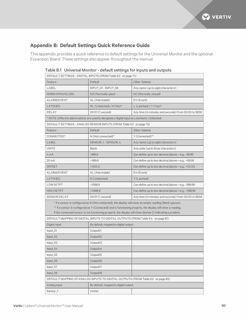
Appendix B: Default Settings Quick Reference Guide
This appendix provides a quick reference to default settings for the Universal Monitor and the optionalExpansion Board. These settings also appear throughout the manual.
DEFAULT SETTINGS - DIGITAL INPUTS (FROM Table 9.2 on page 71)
Feature Default Other Options
LABEL INPUT_01 - INPUT_08 Any name (up to eight characters)
NORM OPEN/CLOSE NO (Normally open) NC (Normally closed)
ALARM/EVENT AL (Alarmable) EV (Event)
LATCHED NL (Unlatched) / N (No)* L (Latched) / Y (Yes)*
DELAY 00:01 (1 second) Any time (in minutes and seconds) from 00:00 to 99:59
* NOTE: Different abbreviations are used to designate a digital input as Latched or Unlatched.
DEFAULT SETTINGS - ANALOG SENSOR INPUTS (FROM Table 9.3 on page 75)
Feature Default Other Options
CONNECTED* N (Not connected)* Y (Connected)**
LABEL SENSOR_1 - SENSOR_4 Any name (up to eight characters)
UNITS Blank Any units (up to three characters)
4 mA -999.9 Can define up to two decimal places—e.g., -99.99
20 mA +999.9 Can define up to two decimal places—e.g., +99.99
OFFSET +000.0 Can define up to two decimal places—e.g., +00.00
ALARM/EVENT AL (Alarmable) EV (Event)
LATCHED N (Unlatched) Y (Latched)
LOW SETPT -0999.9 Can define up to two decimal places—e.g., -999.99
HIGH SETPT +0999.9 Can define up to two decimal places—e.g., +999.99
SENSOR DELAY 00:01 (1 second) Any time (in minutes and seconds) from 00:00 to 99:59
* If a sensor is configured as N (Not connected), the display will show an empty reading (blank spaces).
** If a sensor is configured as Y (Connected) and is functioning properly, the display will show a reading.
If the connected sensor is not functioning properly, the display will show dashes () indicating a problem.
DEFAULT MAPPING OF DIGITAL INPUTS TO DIGITAL OUTPUTS (FROM Table 9.4 on page 81)
Digital input By default, mapped to digital output:
Input_01 Output01
Input_02 Output02
Input_03 Output03
Input_04 Output04
Input_05 Output05
Input_06 Output06
Input_07 Output07
Input_08 Output08
DEFAULT MAPPING OF ANALOG INPUTS TO DIGITAL OUTPUTS (FROM Table 9.5 on page 83)
Analog input By default, mapped to digital output:
Sensor_1 (none)
Table B.1 Universal Monitor - default settings for inputs and outputs
Vertiv | Liebert® Universal Monitor™ User Manual | 117
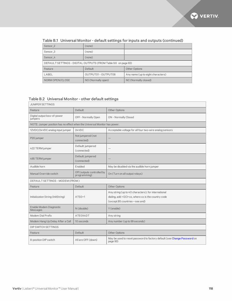
Sensor_2 (none)
Sensor_3 (none)
Sensor_4 (none)
DEFAULT SETTINGS - DIGITAL OUTPUTS (FROM Table 9.6 on page 83)
Feature Default Other Options
LABEL OUTPUT01 - OUTPUT08 Any name (up to eight characters)
NORM OPEN/CLOSE NO (Normally open) NC (Normally closed)
Table B.1 Universal Monitor - default settings for inputs and outputs (continued)
JUMPER SETTINGS
Feature Default Other Options
Digital output loss-of-powerjumpers OFF - Normally Open ON - Normally Closed
NOTE: Jumper position has no effect when the Universal Monitor has power.
12VDC/24VDC analog input jumper 24VDC Acceptable voltage for all four two-wire analog sensors
P20 jumperNot jumpered (not
connected)—
422 TERM jumperDefault: jumpered
(connected)—
485 TERM jumperDefault: jumpered
(connected)—
Audible horn Enabled May be disabled via the audible horn jumper
Manual Override switch Off (outputs controlled byprogramming) On (Turn on all output relays)
DEFAULT SETTINGS - MODEM (FROM )
Feature Default Other Options
Initialization String (InitString) ATS0=1
Any string (up to 40 characters); for international
dialing, add +GCI=xx, where xx is the country code
(except B5 countries—see and)
Enable Modem DiagnosticMessages N (disable) Y (enable)
Modem Dial Prefix ATE0X4DT Any string
Modem Hang Up Delay After a Call 10 seconds Any number (up to 99 seconds)
DIP SWITCH SETTINGS
Feature Default Other Options
8-position DIP switch All are OFF (down) May be used to reset password to factory default (see Change Password onpage 93)
Table B.2 Universal Monitor - other default settings
Vertiv | Liebert® Universal Monitor™ User Manual | 118

OTHER SETTINGS
Feature Default Other Options
Change state of outputs - automaticor manual control
AUTO (automaticcontrol)
Force an output ON / OFF via Manual Output Ctrl menu
Force all outputs ON via hardware switch
Password AAAA Any 4 characters (see Table 9.1 on page 67 for valid characters)
Reset common alarm with silence N (not reset) Y (reset with silence)
Battery connected Y (connected) N (not connected)
Table B.2 Universal Monitor - other default settings (continued)
DEFAULT SETTINGS - DIGITAL INPUTS (FROM Table 9.2 on page 71)
Feature Default Other Options
LABEL INPUT_09 - INPUT_24 Any name (up to eight characters)
NORM OPEN/CLOSE NO (Normally open) NC (Normally closed)
ALARM/EVENT AL (Alarmable) EV (Event)
LATCHED NL (Unlatched) / N (No)* L (Latched) / Y (Yes)*
DELAY 00:01 (1 second) Any time (in minutes and seconds) from 00:00 to 99:59
* NOTE: Different abbreviations are used to designate a digital input as Latched or Unlatched.
DEFAULT MAPPING OF DIGITAL INPUTS TO DIGITAL OUTPUTS (FROM Table 9.4 on page 81)
Digital input By default, mapped to digital output:
Input_09 (none)
Input_10 (none)
Input_11 (none)
.
.
.
(none)
Input_24 (none)
NOTE: By default, no Expansion Board inputs are mapped to any outputs.
DEFAULT SETTINGS - DIGITAL OUTPUTS (FROM Table 9.6 on page 83)
Feature Default Other Options
LABEL OUTPUT09 - OUTPUT16 Any name (up to eight characters)
Table B.3 Expansion Board - default settings for inputs and outputs
Vertiv | Liebert® Universal Monitor™ User Manual | 119
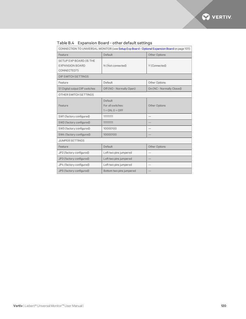
CONNECTION TO UNIVERSAL MONITOR (see Setup Exp Board - Optional Expansion Board on page 101)
Feature Default Other Options
SETUP EXP BOARD (IS THE
EXPANSION BOARD
CONNECTED?)
N (Not connected) Y (Connected)
DIP SWITCH SETTINGS
Feature Default Other Options
S1 Digital output DIP switches Off (NO - Normally Open) On (NC - Normally Closed)
OTHER SWITCH SETTINGS
Feature
Default
For all switches:
1 = ON, 0 = OFF
Other Options
SW1 (factory configured) 11111111 —
SW2 (factory configured) 11111111 —
SW3 (factory configured) 10000100 —
SW4 (factory configured) 10000100 —
JUMPER SETTINGS
Feature Default Other Options
JP2 (factory configured) Left two pins jumpered —
JP3 (factory configured) Left two pins jumpered —
JP4 (factory configured) Left two pins jumpered —
JP5 (factory configured) Bottom two pins jumpered —
Table B.4 Expansion Board - other default settings
Vertiv | Liebert® Universal Monitor™ User Manual | 120


VertivCo.com | Vertiv Headquarters, 1050 Dearborn Drive, Columbus, OH, 43085, USA
© 2017 Vertiv Co. All rights reserved. Vertiv and the Vertiv logo are trademarks or registered trademarks of Vertiv Co. All other names and logos referred toare trade names, trademarks or registered trademarks of their respective owners. While every precaution has been taken to ensure accuracy andcompleteness herein, Vertiv Co. assumes no responsibility, and disclaims all liability, for damages resulting from use of this information or for any errors oromissions. Specifications are subject to change without notice.
SL-31060_REV4_11-17/590-1621-501A
Related Documents


