Libero IDE v9.1 User’s Guide

Welcome message from author
This document is posted to help you gain knowledge. Please leave a comment to let me know what you think about it! Share it to your friends and learn new things together.
Transcript


Actel Corporation, Mountain View, CA 94043 © 2010 Actel Corporation. All rights reserved.
Printed in the United States of America
Part Number: 5-02-9124-26
Release: November 2010
No part of this document may be copied or reproduced in any form or by any means without prior written consent of Actel.
Actel makes no warranties with respect to this documentation and disclaims any implied warranties of merchantability or fitness for a particular purpose. Information in this document is subject to change without notice. Actel assumes no responsibility for any errors that may appear in this document.
This document contains confidential proprietary information that is not to be disclosed to any unauthorized person without prior written consent of Actel Corporation.
Trademarks
Actel and the Actel logotype are registered trademarks of Actel Corporation.
Adobe and Acrobat Reader are registered trademarks of Adobe Systems, Inc.
Mentor Graphics, Precision RTL, Exemplar Spectrum, and LeonardoSpectrum are registered trademarks of Mentor Graphics, Inc.
WaveFormer Lite is a registered trademark of SynaptiCAD, Inc.
Synplify is a registered trademark of Synplicity, Inc.
Sun and Sun Workstation, SunOS, and Solaris are trademarks or registered trademarks of Sun Microsystems, Inc
Synopsys is a registered trademark of Synopsys, Inc.
Verilog is a registered trademark of Open Verilog International.
Viewlogic, ViewSim, ViewDraw and SpeedWave are trademarks or registered trademarks of Viewlogic Systems, Inc.
Windows is a registered trademark and Windows NT is a trademark of Microsoft Corporation in the U.S. and other countries.
UNIX is a registered trademark of X/Open Company Limited.
All other products or brand names mentioned are trademarks or registered trademarks of their respective holders.

Libero IDE v9.1 User’s Guide 3
Table of Contents
What's New in Libero IDE v9.1 ............................................................................ 7
Supported Families ............................................................................................... 8
Project Management ........................................................................................... 11 Libero IDE Design Flow ....................................................................................................................... 12
Project Files ........................................................................................................ 18
Project Options ................................................................................................... 27
Settings ............................................................................................................... 28 Project Manager Project Settings........................................................................................................... 29
Preferences .......................................................................................................... 40
Project Manager Interface ................................................................................... 46 Libero IDE Project Manager ................................................................................................................. 47
Designing with Designer Block Components ....................................................... 59
Creating a Designer Block Component in Libero IDE ......................................... 63 Creating a Designer Block Component in Libero IDE ........................................................................ 64
Creating a Designer Block Component in Designer ............................................. 68
Instantiating a Designer Block Component in Designer ....................................... 72
SmartDesign ....................................................................................................... 75 General Questions ................................................................................................................................. 77 Instantiating your SmartDesign ............................................................................................................. 78 Working with Processor-Based Designs in SmartDesign ..................................................................... 79 Making your Design Look Nice ............................................................................................................ 80 Generating your Design ......................................................................................................................... 81 General Questions ................................................................................................................................. 82 Instantiating Your SmartDesign ............................................................................................................ 83 Working with Processor-Based Designs in SmartDesign ..................................................................... 85 Making your Design Look Nice ............................................................................................................ 86
Getting Started with SmartDesign ....................................................................... 88
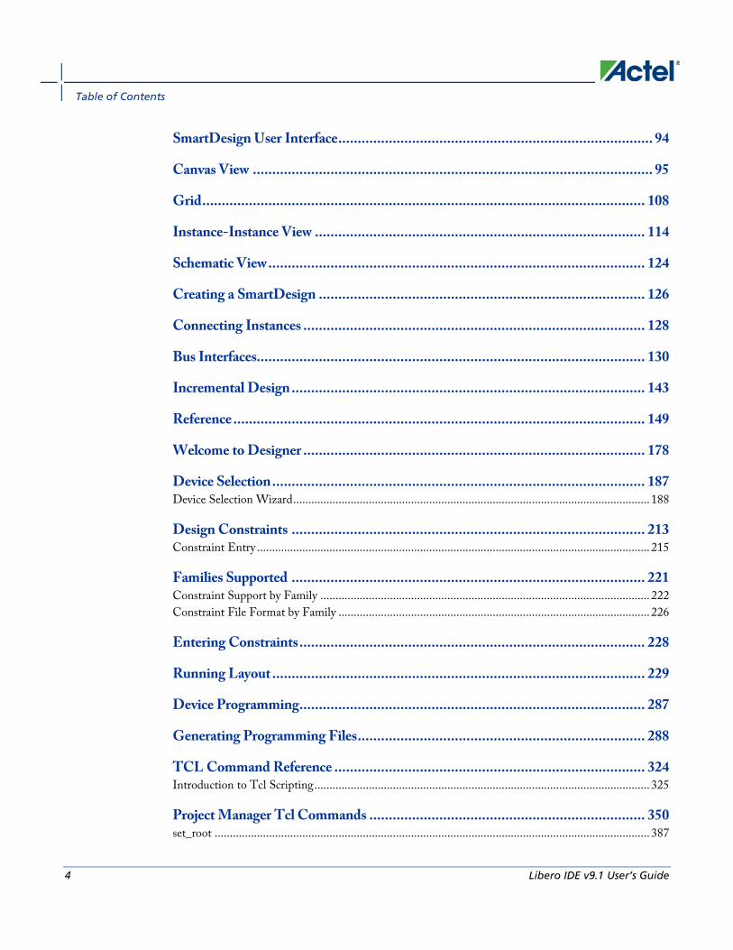
Table of Contents
4 Libero IDE v9.1 User’s Guide
SmartDesign User Interface ................................................................................. 94
Canvas View ....................................................................................................... 95
Grid .................................................................................................................. 108
Instance-Instance View ..................................................................................... 114
Schematic View ................................................................................................. 124
Creating a SmartDesign .................................................................................... 126
Connecting Instances ........................................................................................ 128
Bus Interfaces.................................................................................................... 130
Incremental Design ........................................................................................... 143
Reference .......................................................................................................... 149
Welcome to Designer ........................................................................................ 178
Device Selection ................................................................................................ 187 Device Selection Wizard ...................................................................................................................... 188
Design Constraints ........................................................................................... 213 Constraint Entry .................................................................................................................................. 215
Families Supported ........................................................................................... 221 Constraint Support by Family ............................................................................................................. 222 Constraint File Format by Family ....................................................................................................... 226
Entering Constraints ......................................................................................... 228
Running Layout ................................................................................................ 229
Device Programming ......................................................................................... 287
Generating Programming Files .......................................................................... 288
TCL Command Reference ................................................................................ 324 Introduction to Tcl Scripting ............................................................................................................... 325
Project Manager Tcl Commands ....................................................................... 350 set_root ................................................................................................................................................ 387

Table of Contents
Libero IDE v9.1 User’s Guide 5
Reference .......................................................................................................... 621
Dialog Boxes ..................................................................................................... 623
Product Support ................................................................................................ 633


Libero IDE v9.1 User’s Guide 7
What's New in Libero IDE v9.1
SmartFusion 060 Device Support SmartFusion 060 device support is now enabled in software.
Family Die Package Speed Core Volt Temp Platinum
SmartFusion A2F200M3F_060 256 FBGA STD 1.5V COM, IND YES
-1
288 CS STD
-1
Creating Local Clock Regions in MultiView Navigator For IGLOO, Fusion, ProASIC3, and Axcelerator families, you can use a PDC file to create local clock regions.
For ProASIC PLUS and ProASIC families, you can create local clock regions in ChipPlanner or define them in a GCF file. See the Floorplanning ProASIC/ProASIC PLUS Devices for Increased Performance application note for more information.
For Axcelerator, you can create local clock regions in ChipPlanner or define them in a PDC file.
When you create a local clock region, the selected net and all the macros driven by that net are assigned to the local clock region.
See the Create Local Clock Regions in MVN topic for instructions on how to use the new feature.
Libero IDE Tool Updates Libero IDE v9.1 includes support for new versions of ModelSim, Synplify, and Identify. New licenses are required for the updated OEM tools. See the release notes for the information on the latest version of the IDE software.
Supported Families
8 Libero IDE v9.1 User’s Guide
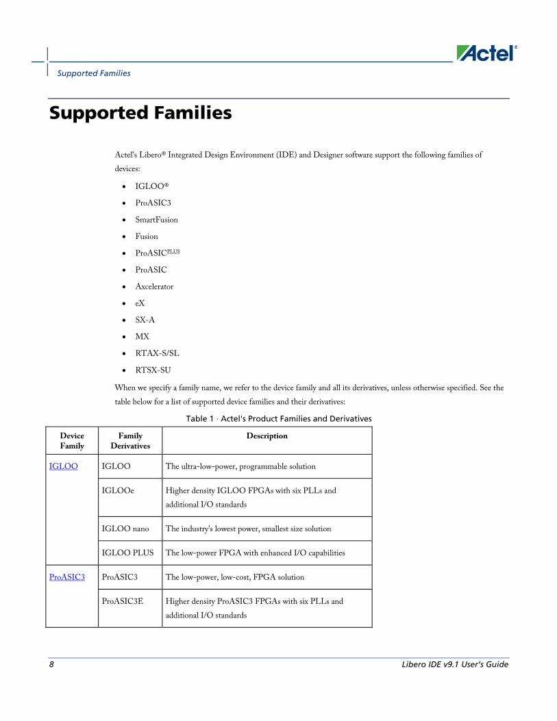
Supported Families
Actel's Libero® Integrated Design Environment (IDE) and Designer software support the following families of devices:
• IGLOO®
• ProASIC3
• SmartFusion
• Fusion
• ProASICPLUS
• ProASIC
• Axcelerator
• eX
• SX-A
• MX
• RTAX-S/SL
• RTSX-SU
When we specify a family name, we refer to the device family and all its derivatives, unless otherwise specified. See the table below for a list of supported device families and their derivatives:
Table 1 · Actel's Product Families and Derivatives
Device Family
Family Derivatives
Description
IGLOO IGLOO The ultra-low-power, programmable solution
IGLOOe Higher density IGLOO FPGAs with six PLLs and additional I/O standards
IGLOO nano The industry’s lowest power, smallest size solution
IGLOO PLUS The low-power FPGA with enhanced I/O capabilities
ProASIC3 ProASIC3 The low-power, low-cost, FPGA solution
ProASIC3E Higher density ProASIC3 FPGAs with six PLLs and additional I/O standards
Creating a New Libero IDE Project
Libero IDE v9.1 User’s Guide 9
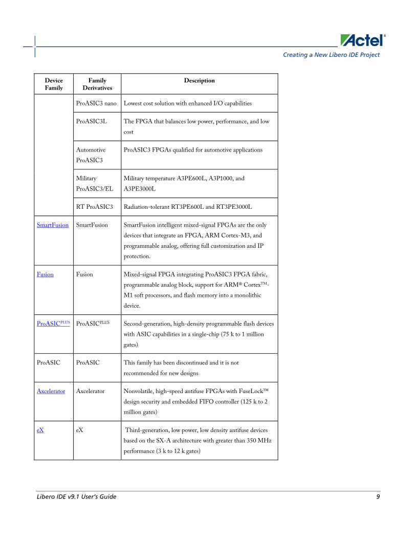
Device Family
Family Derivatives
Description
ProASIC3 nano Lowest cost solution with enhanced I/O capabilities
ProASIC3L The FPGA that balances low power, performance, and low cost
Automotive ProASIC3
ProASIC3 FPGAs qualified for automotive applications
Military ProASIC3/EL
Military temperature A3PE600L, A3P1000, and A3PE3000L
RT ProASIC3 Radiation-tolerant RT3PE600L and RT3PE3000L
SmartFusion SmartFusion SmartFusion intelligent mixed-signal FPGAs are the only devices that integrate an FPGA, ARM Cortex-M3, and programmable analog, offering full customization and IP protection.
Fusion Fusion Mixed-signal FPGA integrating ProASIC3 FPGA fabric, programmable analog block, support for ARM® CortexTM-M1 soft processors, and flash memory into a monolithic device.
ProASICPLUS ProASICPLUS Second-generation, high-density programmable flash devices with ASIC capabilities in a single-chip (75 k to 1 million gates)
ProASIC ProASIC This family has been discontinued and it is not recommended for new designs
Axcelerator Axcelerator Nonvolatile, high-speed antifuse FPGAs with FuseLock™ design security and embedded FIFO controller (125 k to 2 million gates)
eX eX Third-generation, low power, low density antifuse devices based on the SX-A architecture with greater than 350 MHz performance (3 k to 12 k gates)

Supported Families
10 Libero IDE v9.1 User’s Guide
Device Family
Family Derivatives
Description
SX-A SX-A Antifuse devices with 270 MHz system performance and sea-of-modules architecture enabled by Actel's patented metal-to-metal antifuse interconnect elements (12 k to 108 k gates)
MX MX Antifuse devices with 250 MHz system performance and MultiPlex I/O, an architectural feature that supports mixed-voltage systems and delivers high-performance operation at 5.0 V (3 k to 54 k gates)
RTAX-S/SL RTAX-S/SL New generation of high-reliable, radiation-tolerant, antifuse-based FPGAs, designed for space applications with greater than 350 MHz system performance (250 k to 4 million system gates)
RTSX-SU RTSX-SU High-reliable, radiation-tolerant antifuse-based FPGAs with 250 MHz system performance (48 k to 108 k system gates)

Creating a New Libero IDE Project
Libero IDE v9.1 User’s Guide 11
Project Management

Project Management
12 Libero IDE v9.1 User’s Guide
Libero IDE Design Flow The Libero IDE Design Flow consists of six steps:
Step One - Design Creation Plan out your design and use the Design Entry tools (such as SmartDesign) to enter it as either HDL (VHDL or Verilog), structural schematic, or mixed-mode (schematic and RTL).
Step Two - Design Verification - Functional Simulation After you have defined your design, you must verify that it functions the way you intended. After creating a testbench using WaveFormer Pro, use the ModelSim VHDL or Verilog simulator to perform functional simulation on your schematic or HDL design.
If you have an EDIF netlist created with the full version of ModelSim you can import the netlist into your project and skip directly to Design Implementation (step four).
EDIF Flow Support - You can import an EDIF netlist in Project Manager. If you do not have HDL source files in your project, the EDIF netlist is considered to be a source for the flow.
The name of your block as specified in the EDIF netlist is displayed in the Hierarchy under the work library and is automatically Set as Root. The Project Flow Window is updated to show the EDIF flow: synthesis is unavailable and you can go directly to Designer or to Simulation as you would do in the post-synthesis state of the regular HDL flow. If you launch ModelSim, Project Manager automatically creates an HDL netlist.
The Configure Project Flow dialog does not allow you to activate synthesis.
As soon as you import an HDL Source file, the Hierarchy tab does not display the EDIF netlist any more and the Project Flow Window is updated to show the regular HDL flow.
Note: Note: If you have a regular HDL project with a synthesized EDIF netlist and remove all the source files from your project, the Project Design Flow will be changed to the EDIF flow and the EDIF netlist will appear in the Design Hierarchy.
Step Three - Synthesis/EDIF Generation Use Synplify Pro AE to generate your EDIF netlist. You can re-verify your design "post-synthesis" using the VHDL or Verilog ModelSim simulator used in step two.
While all RTL code must be synthesized, pure schematic designs are automatically "netlisted" out via the Libero IDE tools to create a structural VHDL or structural Verilog netlist.
Step Four - Design Implementation After you have functionally verified that your design works, the next step is to implement the design using the Actel Designer software. The Designer software automatically places and routes the design and returns timing information. Use the tools that come with Designer to further optimize your design. Use SmartTime to perform static timing analysis on your design, ChipEditor or ChipPlanner to customize your I/O macro placement, MultiView Navigator for I/O customization, SmartPower for power analysis, and NetlistViewer to view your netlist.
Creating a New Libero IDE Project
Libero IDE v9.1 User’s Guide 13
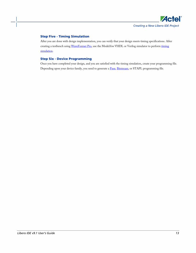
Step Five - Timing Simulation After you are done with design implementation, you can verify that your design meets timing specifications. After creating a testbench using WaveFormer Pro, use the ModelSim VHDL or Verilog simulator to perform timing simulation.
Step Six - Device Programming Once you have completed your design, and you are satisfied with the timing simulation, create your programming file. Depending upon your device family, you need to generate a Fuse, Bitstream, or STAPL programming file.

Project Management
14 Libero IDE v9.1 User’s Guide
Figure 1 · Libero IDE Design Flow

Creating a New Libero IDE Project
Libero IDE v9.1 User’s Guide 15
Creating a New Libero IDE Project Use the New Project Wizard to create a new Libero IDE project in the Project Manager.
To create a new project:
1. From the File menu, choose New Project. The New Project Wizard starts
2. Follow the instructions in the Wizard and click Finish when done.
You must select a new family in order to complete the New Project Wizard and create a new project. You may set the die and package now, or do it later in the design flow.
See Also Opening a project
Saving a project with a new name
new_project
Opening your Libero IDE project The Project Manager opens your most recent project automatically. You can change your default startup preferences in the Startup tab.
To open a different project in Project Manager:
1. From the File menu, choose Close Project.
2. From the File menu, choose Open Project or New Project. If you create a new project the Project Manager starts the New Project Wizard.
TipThe last five saved projects are available from the File menu. From the File menu, choose Recent Projects, and then select the project to open.
You can open an existing project by double-clicking the *.prj file or dragging the *.prj file over the Libero IDE desktop icon.
See Also open_project
Designer Views in the Project Manager Designer views enable you to save different views and backup files for individual projects. You can use views to test different layout runs for a particular project.
You can also check your layout results for each Designer view; to do so, create as many views as you wish, and select them from the Current Designer view drop-down menu (available in the Designer Views Toolbar) and run layout.
To create a new Designer view:
Click the Add Designer view button on the Designer Views toolbar, or from the Current Designer view menu, select Add. The Add Designer View dialog box appears, as shown in the figure below.

Project Management
16 Libero IDE v9.1 User’s Guide
Figure 2 · Add Designer View Dialog Box
You can use your new Designer view to backup your current implementation files. Enter the name of your new view, and choose to keep your current implementation files or revert to the Project Manager defaults. Click OK to continue.
Your new Designer view appears in the list of views on the Designer Views toolbar.
See Also Project Manager Project menu
Saving a Project with a New Name Your project is saved when you close the project. To save the project with another name, use the Save Project As command.
To save the project with a new name:
1. From the Project menu, choose Save Project As. The Save Project As dialog box opens.

Closing and Exiting
Libero IDE v9.1 User’s Guide 17
Figure 3 · Save Project As Dialog Box
2. Enter a new project name.
3. Enter a new project location, or click Browse to specify a new location.
4. Select the Copy Links locally checkbox if you have files linked to your current project and want to copy the links into your new project.
5. Specify which Files (All, Project files only, or None) and Designer Views (All, Current view only, or None) to copy into the new project.
6. Click OK.
See Also save_as_project
Closing and Exiting Your project is automatically saved when closed. To explicitly save your project, use File > Save Project. To save it with another name, use the Save Project As command.
To close a project, from the Project menu, choose Close Project.
To exit Libero IDE, from the Project menu, choose Exit.
See Also Creating a new project
Opening a project
Saving a project with a new name

Project Files
18 Libero IDE v9.1 User’s Guide
Project Files
Project Sources Project sources are any design files that make up your design. These can include schematics, HDL files, simulation files, testbenches, etc. Anything that describes your design or is needed to program the device is a project source.
Source files appear in the Project Flow window. The Hierarchy tab displays the structure of the design modules as they relate to each other, while the Files tab displays all the files that make up the project.
The design description for a project is contained within the following types of sources:
• Schematics
• HDL Files (VHDL or Verilog)
• SmartDesign components
One source file in the project is the top-level source for the design. The top-level source defines the inputs and outputs that will be mapped into the devices, and references the logic descriptions contained in lower-level sources. The referencing of another source is called an instantiation. Lower-level sources can also instantiate sources to build as many levels of logic as necessary to describe your design.
File Linking The Project Manager enables you to link to files not managed in your Libero IDE project. Linked files are useful if you want to preserve a file in an archive, or if more than one person is using a file and it is impractical to store it on your local machine. If you link to external files and rename your project, the Project Manager asks if you want to copy the external files into your project or continue using the link. Note that some files (such as schematics) cannot be linked.
Some project sources can be imported.
Sources for your project can include:
Source File Extension
Schematic *.1-9
Verilog Module *.v
VHDL Entity *.vhd
SmartDesign Component *.vhd
Testbench *.vhd
Stimulus *.tim

New Files
Libero IDE v9.1 User’s Guide 19
Source File Extension
Programming Files *.afm; *.prb
See Also Creating a Schematic Source file
Creating HDL Sources
Generating a Bitstream file
Generating a Fuse file
Generating Programming files
New Files You can create new files from the Project Manager. New file types include:
• Schematic
• SmartDesign Component
• CoreConsole Component
• IP Component
• VHDL Source File
• Verilog Source File
• Stimulus
• Stimulus HDL File
• SDC File (sdc)
• Physical Design Constraint File (pdc)
• DO File
• VHDL Template
• Verilog Template
To create a new file:
1. From the File menu, choose New.
2. Select the File type and type a name.
3. Click OK. The appropriate application starts. The saved file is added to your Libero IDE project.

Project Files
20 Libero IDE v9.1 User’s Guide
Importing Files Anything that describes your design, or is needed to program the device, is a project source. These may include schematics, HDL files, simulation files, testbenches, etc. Import these source files directly into your .
To import a file:
1. From the File menu, choose Import Files.
2. In Files of type, choose the file type.
3. In Look in, navigate to the drive/folder where the file is located.
4. Select the file to import and click Open.
Notes:
• You cannot import a Verilog File into a VHDL project and vice versa.
• CoreConsole components include all the files needed by the Project Manager in your project folder. Libero IDE lists the CoreConsole component in the Project Manager along with its files (each core includes its own block symbol files, HDL source files, constraint files, implementation files, memory files, etc.).
• When you import a CoreConsole component, the Project Manager creates a new directory in your project folder called coreconsole that includes all the required CoreConsole files. Project Manager preserves the structure of the original CoreConsole directory, except for the ViewDraw symbol - it gets copied into the viewdraw folder in your project.
File Types for Import
File Type File Extension
ViewDraw Symbol *.1-9
ViewDraw Schematic *.1-9
Behavioral and Structural VHDL; VHDL Package *.vhd, *.vhdl
Design Block Core *.gen
Verilog Include *.h
Behavioral and Structural Verilog *.v
Stimulus *.vhd, * .vhdl, *.v
EDIF Netlist *.edn

Libero IDE file types
Libero IDE v9.1 User’s Guide 21
File Type File Extension
CoreConsole Project (v1.1 and 1.2 only) *.ccp
Simulation file required by CoreConsole *.bfm
Memory file *.mem
Components (Designer Blocks, Synplify DSP and CoreConsole components) *.cxf
See Also Project sources
import_files
Libero IDE file types When you create a new project in the Libero IDE Project Manager it automatically creates new directories and project files. Your project directory contains all of your 'local' project files. If you import files from outside your current project, the files must be copied into your local project folder. (The Project Manager enables you to manage your files as you import them.)
Depending on your project preferences and the version of Libero IDE you installed, the Project Manager creates directories for your project.
The top level directory (<project_name>) contains your PRJ file; only one PRJ file is enabled for each Libero IDE project.
component directory - Stores your SmartDesign components (SDB and CXF files) for your Libero IDE project.
constraint directory - All your constraint files (SDC, PDC, GCF, DCF, etc.)
coreconsole directory - Default directory for all the CoreConsole files created in your Libero IDE project.
designer directory - ADB files (Actel Designer project files), -_ba.SDF, _ba.v(hd), STP, PRB (for Silicon Explorer), TCL (used to run designer), impl.prj_des (local project file relative to revision), designer.log (logfile)
Note: Note: The Actel ADB file memory requirement is equivalent to 2x the size of the ADB file. If your computer does not have 2x the size of your ADB file's memory available, please make memory available on your hard drive.
hdl directory - all hdl sources. *.vhd if VHDL, *.v and *.h if Verilog
phy_synthesis directory - _palace.edn, _palace.gcf, palace_top.rpt (palace logfile) and other files generated by PALACE
simulation directory - meminit.dat, modelsim.ini files
smartgen directory - GEN files and LOG files from generated cores

Project Files
22 Libero IDE v9.1 User’s Guide
stimulus directory - BTIM and VHD stimulus files
synthesis directory - *.edn, *_syn.prj (Synplify log file), *.psp (Precision project file), *.srr (Synplify logfile), precision.log (Precision logfile), exemplar.log (Leonardo logfile), *.tcl (used to run synthesis) and many other files generated by the tools (not managed by Libero IDE)
viewdraw directory - viewdraw.ini files
Mixed-HDL Support in Libero IDE You must have ModelSim PE or SE to use mixed HDL in the Libero IDE. Also, you must have Synplify Pro to synthesize a mixed-HDL design.
When you create a project, you must select a preferred language. The HDL files generated in the flow (such as the post-layout netlist for simulation) are created in the preferred language.
The language used for simulation is the same language as the last compiled testbench. (E.g. if tb_top is in verilog, <fam>.v is compiled.)
If your preferred language is Verilog, the post-synthesis and post-layout netlists are in Verilog 2001. You cannot import these netlists back into Designer; the Designer reader only accepts Verilog 95.
Saving Files Files and projects are saved when you close them.
To save an active file:
• From the File menu, choose Save or Save As.
• Click the Save button in the toolbar.
Saving Files in the Libero IDE Project Manager If you want to back up your Libero IDE Project Manager PRJ, Designer ADB, or other Project Manager project files, create a new of your design. Do not use the Save As function in Designer. Instead, use Add Designer view in the Libero IDE Project Manager.
Deleting Files Files can be deleted from the current project or from the disk.
To delete a file from the project:
1. Select the Files tab in the Design Explorer window.
2. Right-click the file and choose Delete from Project. The file remains on your disk.

Finding Files
Libero IDE v9.1 User’s Guide 23
To delete a file from your project and the disk:
1. Select the Files tab in the Design Explorer window.
2. Right-click the file and choose Delete from Disk and Project. The file is deleted from your disk and is no longer part of any project.
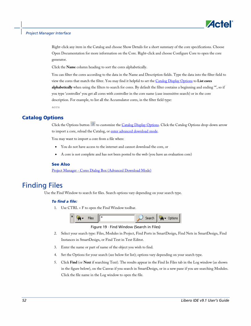
Finding Files Use the Find Window to search for files. Search options vary depending on your search type.
To find a file:
1. Use CTRL + F to open the Find Window toolbar.
Figure 4 · Find Window (Search in Files)
2. Select your search type: Files, Modules in Project, Find Ports in SmartDesign, Find Nets in SmartDesign, Find Instances in SmartDesign, or Find Text in Text Editor.
3. Enter the name or part of name of the object you wish to find.
4. Set the Options for your search (see below for list); options vary depending on your search type.
5. Click Find (or Next if searching Text). The results appear in the Find In Files tab in the Log window (as shown in the figure below), on the Canvas if you search in SmartDesign, or in a new pane if you are searching Modules. Click the file name in the Log window to open the file.
Figure 5 · Find In Files Tab in Project Manager Log Window
Search in Files (Files button) Match case: Select to search for case-sensitive occurrences of a word or phrase. This limits the search so it only locates text that matches the upper- and lowercase characters you enter.
Match whole word: Select to match the whole word only.
In files/file types: Select a file type to narrow your search.
In folder: Select a folder. Click the browse button to navigate to a different folder.

Project Files
24 Libero IDE v9.1 User’s Guide
Search Modules in Project (Modules button) Match case: Select to search for case-sensitive occurrences of a word or phrase. This limits the search so it only locates text that matches the upper- and lowercase characters you enter.
Match whole word: Select to match the whole word only.
Overwrite previous results: Clears the contents of the Log window and writes the new results.
Append to previous results: Appends the new results to the contents of the log window. This option is useful if you are running several searches in succession and want to export the results.
Existing Pane: Displays your search results in an existing pane in the Log window.
New Pane: Displays your search results in a new pane in the Log window with a name you specify.
Find Ports / Find Nets / Find Instances in SmartDesign These searches are available only when you have a SmartDesign open. SmartDesign highlights your search results for ports / nets / instances on the Canvas.
Match case: Select to search for case-sensitive occurrences of a port / net / instance. This limits the search so it only locates the objects that match the upper- and lowercase characters you enter.
Overwrite previous results: Clears any currently selected ports / nets / instances in your design before selecting the matching ports / nets/ instances.
Append to previous results: Appends any new matches to the currently selected ports / nets/ instances in your design.
Find Text in Text Editor (Text button) Previous: Proceed to previous instance of found text.
Next: Proceed to next instance of found text.
Mark All: Marks all instances of the found text.
Match case: Select to search for case-sensitive occurrences of a word or phrase. This limits the search so it only locates text that matches the upper- and lowercase characters you enter.
Match whole word: Select to match the whole word only.
Replace with: Replaces the text you searched with the contents of the field. Click Replace All to replace all instances of the found text with the contents of the field.
Find Window You can search for modules and components in the Hierarchy with the Find window (see figure below). You can search by name, library or type (All, Components, HDL modules, VHDL package and Schematic) and use wildcards to refine your search.
Linking files
Libero IDE v9.1 User’s Guide 25
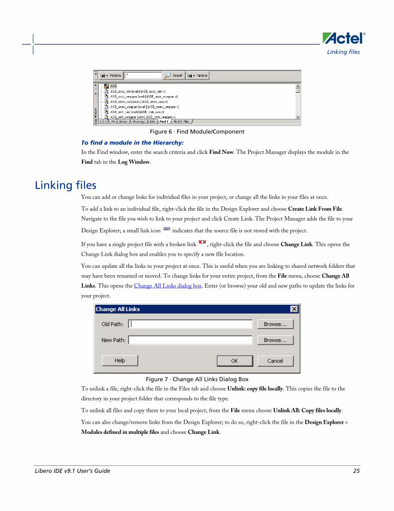
Figure 6 · Find Module/Component
To find a module in the Hierarchy:
In the Find window, enter the search criteria and click Find Now. The Project Manager displays the module in the Find tab in the Log Window.
Linking files You can add or change links for individual files in your project, or change all the links in your files at once.
To add a link to an individual file, right-click the file in the Design Explorer and choose Create Link From File. Navigate to the file you wish to link to your project and click Create Link. The Project Manager adds the file to your
Design Explorer; a small link icon indicates that the source file is not stored with the project.
If you have a single project file with a broken link , right-click the file and choose Change Link. This opens the Change Link dialog box and enables you to specify a new file location.
You can update all the links in your project at once. This is useful when you are linking to shared network folders that may have been renamed or moved. To change links for your entire project, from the File menu, choose Change All Links. This opens the Change All Links dialog box. Enter (or browse) your old and new paths to update the links for your project.
Figure 7 · Change All Links Dialog Box
To unlink a file, right-click the file in the Files tab and choose Unlink: copy file locally. This copies the file to the directory in your project folder that corresponds to the file type.
To unlink all files and copy them to your local project, from the File menu choose Unlink All: Copy files locally.
You can also change/remove links from the Design Explorer; to do so, right-click the file in the Design Explorer > Modules defined in multiple files and choose Change Link.

Project Files
26 Libero IDE v9.1 User’s Guide
Reserved Actel Keywords For a complete list of reserved Actel keywords, see the online help.
VHDL Library - Add, Remove, or Rename
Libero IDE v9.1 User’s Guide 27
Project Options
VHDL Library - Add, Remove, or Rename Libero IDE enables you to manage your VHDL libraries from within the Project Manager.
From the Project menu, select VHDL Library and Add, Remove, or Rename to update your library.
When you add a library it appears in your Hierarchy.

Settings
28 Libero IDE v9.1 User’s Guide
Settings
Project Settings: Device
Libero IDE v9.1 User’s Guide 29
Project Manager Project Settings Use the Options dialog box to specify your project settings for the currently open project.
From the Project menu, choose Settings to open the dialog box. View and edit the preferences and click OK. To revert to the default settings, click Default.
Options include:
• Project Settings: Device
• Project Settings: Flow
• Project Settings: Simulation
Project Settings: Device Use the Device tab in the Project Settings dialog box to change the die and package for your project.

Settings
30 Libero IDE v9.1 User’s Guide
Figure 8 · Project Settings: Device Tab
You can use the Family Combo check box to change your family from ProASIC3 to ProASIC3E. No other family changes are enabled.
To change the die and/or package:
1. From the Project menu, choose Settings. The Project Settings dialog box appears.
2. Select a die and package from each list and click OK.

Project Settings: Flow
Libero IDE v9.1 User’s Guide 31
Project Settings: Flow Use the Flow tab in the Project Settings dialog box to configure your settings for HDL netlists, the DRC checker, ModelSim, ViewDraw, and the rest of your design flow.
Figure 9 · Project Settings: Flow tab
General Preferred HDL Type - Set your HDL type to VHDL or Verilog.
Enable Designer Block creation - Enables you to create Designer Blocks in the Project Manager. Designer Blocks are useful if you want to create a block and re-use it in several designs. See the Designer Block help for more information.
HDL Netlists The HDL project level options enable you to specify whether or not you want to generate your HDL netlists after synthesis.
• Generate an HDL netlist immediately after synthesis - Select this option if you run post-synthesis simulation. If you do not run post-synthesis simulation, de-select this option to start Designer more quickly.
DRC Run DRC immediately after synthesis evaluates the netlist generated by Synplify to ensure it does not have any connection problems.

Settings
32 Libero IDE v9.1 User’s Guide
ModelSim Update modelsim.ini automatically may be useful if the Project Manager does not create a valid modelsim.ini file. Click the checkbox to enable.
ViewDraw Generate HDL netlist after a Save&Check in ViewDraw - Useful if you wish to eliminate the manual step of generating your HDL netlist after a Save&Check.
Update viewdraw.ini automatically - May be useful if the Project Manager does not create a valid viewdraw.ini file. Click the checkbox to enable.
File Detection Detect new files on disk automatically enables the Project Manager to see new files when you add them to your project. If you deselect this option, you must add the new files manually.
SmartGen core Generation Generate resource report by default creates and saves the Design Block (core) resource report after you generate a core.
FlashPro options Input programming file for FlashPro sets your input programming file. PDB files enable you to configure the security settings in FlashROM and Flash Memory from FlashPro.
Project Settings: Simulation Use the Simulation tab to set your simulation values in your project. You can set change how the Project Manager handles Do files in simulation, import your own Do files, set simulation run time, and change the resolution of your simulation. You can also change your library mapping in this dialog box.

Project Settings: Simulation
Libero IDE v9.1 User’s Guide 33
Figure 10 · Project Settings: Simulation Tab
DO file Use automatic DO file - Select if you want the Project Manager to automatically create a DO file that will enable you to simulate your design.
User defined DO file - Enter the DO file name or click the browse button to navigate to it.
Simulation Run Time - Specify how long the simulation should run. If the value is 0, or if the field is empty, there will not be a run command included in the run.do file.
Testbench module/entity name - Specify the name of your testbench entity name. Default is “testbench,” the value used by WaveFormer Pro.

Settings
34 Libero IDE v9.1 User’s Guide
Top Level instance name in the testbench - Default is <top_0>, the value used by WaveFormer Pro. The Project Manager replaces <top> with the actual top level macro when you run ModelSim.
DO command parameters - Text in this field is added to the DO command.
Generate VCD file - Click the checkbox to generate a VCD file.
VCD file name - Specifies the name of your generated VCD file. The default is power.vcd; click power.vcd and type to change the name.
Waveforms Include DO file - Including a DO file enables you to customize the set of signal waveforms that will be displayed in ModelSim.
Included DO File - Use the browse button to navigate to the included DO file.
Display waveforms for - You can display signal waveforms for either the top-level testbench or for the design under test. If you select top-level testbench then Project Manager outputs the line 'add wave /testbench/*' in the DO file run.do. If you select DUT then Project Manager outputs the line 'add wave /testbench/*' in the run.do file.
Log all signals in the design - Saves and logs all signals during simulation.
Vsim Command SDF timing delays - Select Minimum (Min), Typical (Typ), or Maximum (Max) timing delays in the back-annotated SDF file.
Resolution
The default is family specific, but you can customize it to fit your needs.
Family Default Resolution
ACT1, ACT2, ACT3 1 ns
MX 1 ns
DX 1 ns
SX, SX-A 1 ns
eX 1 ns
Axcelerator 1 ps
ProASIC 1 ps
ProASICPLUS 1 ps

Setting Your Project Profile
Libero IDE v9.1 User’s Guide 35
Family Default Resolution
ProASIC3 1 ps
ProASIC3E 1 ps
IGLOO 1 ps
IGLOOe 1 ps
Fusion 1 ps
Vsim additional options - Text entered in this field is added to the vsim command.
Libraries Use default library path - Sets the library path to the default from your Libero IDE installation.
Library path - Enables you to change the mapping for your VHDL library. Type in the pathname or click the Browse button to navigate to your library directory.
Library command - Select the radio button to ignore (Do not compile), Refresh, Compile the library, Delete and recompile, or Refresh and Compile the library.
To access this dialog, from the Project menu, choose Settings and then select the Simulation tab.
Setting Your Project Profile Each Libero IDE project can have a different profile, enabling you to integrate different tools with different projects.
To set or change your project profile:
1. From the Project menu, choose Profiles.
• To add a tool: Click Add and select which type of tool. Fill out the tool profile and click OK.
• To change a tool profile: After selecting the tool, click to Edit to select another tool, change the tool name, or change the tool location.
• To remove a tool from the project:After selecting a tool, click Remove.
2. When you are done, click OK.
See Also Add or Edit Profile dialog box
Starting LeonardoSpectrum
Starting Precision

Settings
36 Libero IDE v9.1 User’s Guide
Source Files for Synthesis The Source Files for Synthesis dialog box enables you to set the synthesis file order in the Project Manager.
Figure 11 · Organize Source Files for Synthesis Dialog Box
De-select the Use default list from Project Manager checkbox to Add/Remove source files for synthesis.
To specify the synthesis file order:
1. From the Project menu, choose File Organization > Source Files for Synthesis. The Organize Source Files for Synthesis dialog box appears.
2. De-select the Use default list from Project Manager checkbox to Add/Remove source files for synthesis. Click the Default button to reset the options to the original settings.
3. Click OK.
Source Files for Simulation The Source Files for Simulation dialog box enables you to set the simulation file order in the Project Manager.

Designer Constraint File Organization
Libero IDE v9.1 User’s Guide 37
Figure 12 · Organize Source Files for Simulation Dialog Box
De-select the Use default list from Project Manager checkbox to Add/Remove source files for simulation.
To specify the simulation file order:
1. From the Project menu, choose File Organization > Source Files for Simulation. The Organize Source Files for Simulation dialog box appears.
2. De-select the Use default list from Project Manager checkbox to Add/Remove source files for simulation. Click the Default button to reset the options to the original settings.
3. Click OK.
Designer Constraint File Organization Use the Organize Constraints for Designer dialog box to specify the constraint files that you want Designer to use for your current module.

Settings
38 Libero IDE v9.1 User’s Guide
Figure 13 · Organize Constraints for Designer Dialog Box
You can also specify the order in which you want to import these files into Designer and consider dependencies between them.
To select constraint files for Designer, select a file in the Constraint files in the project list and click the Add button. Libero adds the file to the Constraint files for Designer list.
To remove constraint files from Designer, select a file in the Constraint files for Designer list and click the Remove button. The Project Manager removes the files from the Constraint files for Designer list.
Use the Up and Down arrow buttons to specify the order that you want your constraint files imported into Designer.
When a constraint file generated by a tool is added to the list of constraint files for Designer, it is added before any user constraint files. You can change the order of any file, but Actel recommends that you do not pass user constraint files before tool constraint files.
If you add both Synplify and PALACE constraint files to the list, the recommended (and default) order is:
1. Synplify constraint file
2. PALACE constraint files
3. User constraint files
Use Designer PDC - Enables you to export a PDC file from your design so you can use it for incremental flow. The Project Manager opens the ADB, exports a PDC file, and replaces all input PDC files with the updated version.
Stimulus File Organization Use the Organize Stimulus dialog box (below) to manage the stimulus files in your project.
Before you can run simulation, you must associate a testbench. If you attempt to run simulation without an associated testbench, the Project Manager asks you to associate a testbench or open ModelSim without a testbench. You can use the Organize Stimulus dialog box to set associate your testbench for simulation.

Stimulus File Organization
Libero IDE v9.1 User’s Guide 39
Figure 14 · Organize Stimulus Files Dialog Box
To organize your stimulus files:
1. From the Project menu, choose File Organization > Stimulus. This opens the Organize Stimulus dialog box.
2. In the Organize Stimulus dialog box, all the stimulus files in the current project appear in the Stimulus Files in the Project list box. Files already associated with the block appear in the Associated Files list box.
In most cases you will only have one testbench associated with your block. However, if you want simultaneous association of multiple testbench files for one simulation session, as in the case of PCI cores, add multiple files to the Associated Files list box.
To add a testbench: Select the testbench you want to associate with the block in the Stimulus Files in the Project list box and click Add to add it to the Associated Files list.
To remove a testbench: To remove or change the file(s) in the Associated Files list box, select the file(s) and click Remove.
To order testbenches: Use the up and down arrows to define the order you want the testbenches compiled. The top level-entity should be at the bottom of the list.
3. When you are satisfied with the Associated File(s) list, click OK. The stimulus buttons in the Project Manager Project Flow window turn green to alert you that a testbench has been associated with the block.

Preferences
40 Libero IDE v9.1 User’s Guide
Preferences
Setting Preferences Use the Preferences dialog to customize the Libero IDE Project Manager.
To set your preferences:
1. From the Project menu, choose Preferences.
2. Specify your preferences on each of the tabs.
Updates
Proxy Settings
Startup (File association)
Log
Text Editor
Advanced
PDF reader (UNIX only)
Web browser (UNIX only)
3. Click OK.
Note: Note: These preferences are stored on a per-user basis. These preferences are not project specific.
Updates Actel strongly recommends that you check at least once a week for fixes, updates, and enhancements for your Actel software.
Note: Note: This feature requires an internet connection.
Note: The version checking feature is not available for Linux.
The Updates tab in the Preferences dialog box allows you to set your automatic software update preferences.
To set your automatic software update preferences:
1. From the Project menu, choose Preferences > Updates.
2. Choose one of the following options:
• Automatically check for updates at startup: Select to be notified of updates when you start Designer.
• Remind me to check for updates at startup: Select to be asked if you want to check for a software update when you start Libero IDE.

Setting Your Proxy
Libero IDE v9.1 User’s Guide 41
• Do not check for updates or remind me at startup: Select if you do not want to check for software updates at startup.
To manually check for software updates, from the Help menu, choose Check for Software Updates, click OK.
IP Updates Set your IP update options. When downloaded, IP appears in the Catalog.
See Also Setting preferences
Setting Your Proxy An FTP connection is used to update some data files. Use the Proxy tab in the Preferences dialog box to enter your proxy name if you use a proxy server.
1. From the Project menu, choose Preferences.
2. Click the Proxy tab.
3. If you use a Proxy server, click the check box and enter the name.
4. Click OK to dismiss the Preferences dialog box.
See Also Version Checking
Startup Tab Several programs, including the Libero IDE Project Manager, create files with the PRJ extension. If you want the Project Manager to start whenever you double-click a PRJ file, you need to set up Project Manager as the default editor for PRJ files.
You must have rights to modify the HKEY_CLASSES_ROOT of the registry of the machine to set Libero IDE Project Manager file association. If you do not have rights to modify the registry, Libero IDE ignores your settings.
To make the Project Manager the default editor for PRJ files:
1. From the Project menu, choose Preferences.
2. Click the Startup tab.
3. Select the check box to associate Libero IDE Project Manager with PRJ files.
To open the most recently used project at startup:
1. From the Project menu, choose Preferences.
2. Click the Startup tab.
3. Select the check box to open the most recently used project at startup.

Preferences
42 Libero IDE v9.1 User’s Guide
Setting Your Log Window Preferences Errors, Warnings, and Informational messages are color-coded in the Project Manager log window. You can change the default colors by using the log Window tab in the Preferences dialog box.
Window Colors To change colors in the log window:
1. From the Project menu, choose Preferences.
2. Click the Log Window tab in the Preferences Dialog Box.
3. Select your new default colors and click OK.
Click the Restore Defaults button to reset the log window colors to their original settings.
The default color settings for the log window are:
Message Type Colors
Errors Red
Warnings Light Blue
Informational Black
Links Dark Blue
Clear log window automatically - (unchecked by default) Clears the Project Manager log window each time you close or open a new project. Clear the box if you want Project Manager to leave the log information after you close a project.
Log Size Sets a maximum log buffer size for your log window. Uncheck the box for no limit on size; click the Restore Default button to reset the buffer size to its original setting.
Text Editor You can use the Libero IDE HDL text editor or another text editor.
To set your text editor preferences:
1. From the Project menu, choose Preferences.
2. Click TextEditor.

Text Editor
Libero IDE v9.1 User’s Guide 43
Figure 15 · Preferences: Text Editor
2. Set your options and click OK.
Libero text editor options
• Use Libero text editor: Select to use the Libero HDL text editor.
• Replace tab with spaces: Enter the number of spaces you want entered when using the tab key.
• Open programming/debugging files as read-only:Select to specify read-only permission to .stp and .prb files.
User defined text editor
• User defined text editor: Deselect use Libero text editor to activate this area. Enter the .exe location of the text editor.
• Additional parameters: Use to specify other settings to pass to the text editor. Typically, it is not necessary to modify this field.
User Template Location - Sets the path where your user templates are exported

Preferences
44 Libero IDE v9.1 User’s Guide
Advanced (Libero IDE Project Manager) The Advanced tab in the Project Manager preferences dialog box sets Designer and HDL options. To open the Advanced tab, from the Project menu, choose Preferences and click the Advanced tab.
Designer Options Organize constraint files before running synthesis - When this option is enabled, the Organize Constraints dialog box automatically opens before your synthesis tool UI appears. This dialog enables you to select the constraint files that will be passed your synthesis tool.
Organize constraint files before creating a new ADB - When this option is enabled, the Organize Constraints for Designer dialog box automatically opens before the Designer UI. This dialog enables you to select the constraint files that will be passed to Designer. The purpose of this option is to enable you to organize your constraint files before creating a new ADB.
Organize CDB files before creating a new ADB - When this option is enabled, the Organize Constraints dialog box automatically opens before the Designer UI. This dialog enables you to select the CDB files that will be passed to Designer. The purpose of this option is to enable you to organize your CDB files before creating a new ADB.
Warn me when Designer Block mode is changed triggers an automatic warning when you enable/disable Designer Block mode. Designer Block mode has limitations that may affect your design if you enable/disable the mode accidentally. Deselect this option to disable the warning.
HDL Templates Warn me when templates are only copied to the clipboard enables a warning when you do not have an open HDL file and the template is copied to the clipboard. You must open an HDL file and past the clipboard contents manually. Deselect this option to disable the warning.
IP Cores Warn me before:
Simulation of the wrapper of an IP core - Simulation of the top-level wrapper is incomplete relative to simulation of the core itself. Click the checkbox to enable a warning when you simulate a wrapper. Actel recommends that you run simulation on the core, and run synthesis on the wrapper (see warning below).
Synthesis of an IP core - Synthesis of the core is incomplete relative to synthesis of the wrapper. Click the checkbox to enable/disable a warning if you synthesize an IP core instead of the wrapper. Actel recommends that you run synthesis on the wrapper, and run simulation on the core (see warning above).
Launching a tool on a component with errors - De-select this option to prevent warnings when you launch a tool on a component that has errors in it. This may be useful if you wish to leave some elements of the component incomplete and finish them at a later time. If you de-select this option, you will not have to see a warning every time you open the component.

Environment Variables
Libero IDE v9.1 User’s Guide 45
Launching a tool on an out of date component - De-select this option if you do not wish to see warning messages related to out of date components. A component is out of date if a newer version is available.
Warn me when:
A project is open and new cores are available - Shows the New Cores Available message when new cores are available for download. Deselect this option to hide the messages.
I instantiate a core that has a newer version - Shows a warning when you instantiate a core that has a newer version available for download.
Environment Variables The software included with the Libero IDE sets new environment variables during installation. They are summarized below.
Libero IDE/Designer - System Variables: PATH: <Libero install directory>\Designer\bin
PATH: <Program Files>\Common Files\Actel
Note: Note: Program Files can be set on C:, D:, etc. it depends on the setting on your system's environment settings.
ViewDraw - User Variables: PATH: <Libero install directory>\ViewDraw\bin
PATH_Old: <a copy of original PATH. If there was no existing PATH when ViewDraw was installed, ViewDraw still creates this variable with an empty value>
ACTELWDIR: <Libero install directory>\ViewDraw\bin
ACTELWDIR_OLD: <a copy of original ACTELWDIR. If ACTELWDIR did not exist when ViewDraw was being installed, the value of this variable is just a copy of ACTELWDIR>.
Palace - System Variables: PALACE_ROOTDIR: <Libero install directory>\PALACE
PATH: <Libero install directory>\PALACE\bin
ModelSim -System Variables: PATH: <Libero install directory>\Model\win32acoem

Project Manager Interface
46 Libero IDE v9.1 User’s Guide
Project Manager Interface
Hierarchy in the Design Explorer
Libero IDE v9.1 User’s Guide 47
Libero IDE Project Manager The Libero IDE Project Manager workspace integrates design tools, streamlines the design flow, manages all design and log files, and passes design data between tools.
The Design Explorer Window includes the Hierarchy, Files, and Information windows.
At right are the Project Flow Window, the HDL Editor, and SmartDesign. The Catalog window lists all IP Cores, VHDL and Verilog Templates, and Bus Interface definitions.
The default location for the Find and Log windows is below the Project Flow Window.
You can customize the Project Manager interface to meet your needs. Close or reposition the Design Explorer, Catalog, Information, Find, and Log windows with the control buttons in the top right of each window; the pin shrinks the window into an expandable bar on the left, the arrow collapses/expands the docked window, and the X closes it.
To re-open a closed window, from the View menu, choose View > Toolbars > <name of window>.
The Project Manager also includes toolbars and menus.
See Also Creating a new project
Files tab
Navigating the work environment
Project Settings
Hierarchy in the Design Explorer The Hierarchy tab displays a hierarchical representation of the design based on the source files in the project. The Project Manager continuously analyzes and updates source files and updates the hierarchy. The Hierarchy tab (see figure below) displays the structure of the modules and components as they relate to each other.
Project Manager Interface
48 Libero IDE v9.1 User’s Guide
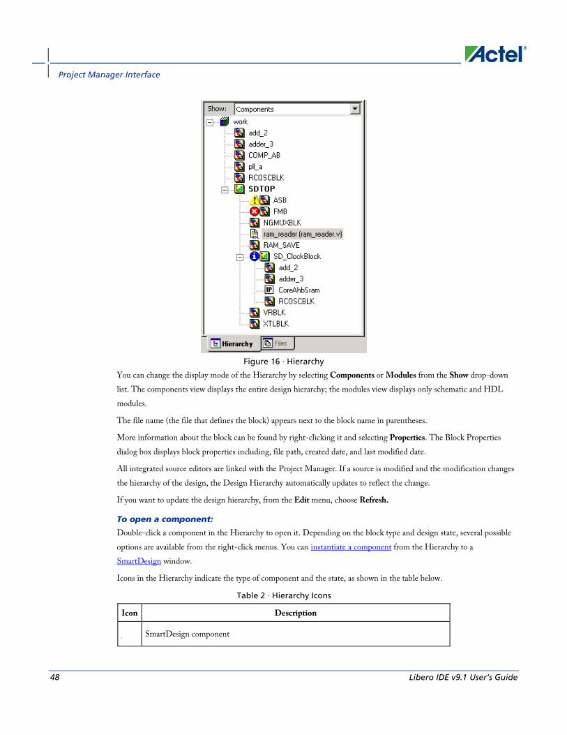
Figure 16 · Hierarchy
You can change the display mode of the Hierarchy by selecting Components or Modules from the Show drop-down list. The components view displays the entire design hierarchy; the modules view displays only schematic and HDL modules.
The file name (the file that defines the block) appears next to the block name in parentheses.
More information about the block can be found by right-clicking it and selecting Properties. The Block Properties dialog box displays block properties including, file path, created date, and last modified date.
All integrated source editors are linked with the Project Manager. If a source is modified and the modification changes the hierarchy of the design, the Design Hierarchy automatically updates to reflect the change.
If you want to update the design hierarchy, from the Edit menu, choose Refresh.
To open a component:
Double-click a component in the Hierarchy to open it. Depending on the block type and design state, several possible options are available from the right-click menus. You can instantiate a component from the Hierarchy to a SmartDesign window.
Icons in the Hierarchy indicate the type of component and the state, as shown in the table below.
Table 2 · Hierarchy Icons
Icon Description
SmartDesign component

Files Tab
Libero IDE v9.1 User’s Guide 49
Icon Description
SmartDesign component with HDL netlist not generated
IP core was instantiated into SmartDesign but the HDL netlist has not been generated
Core
Error during core validation
Updated core available for download
HDL netlist
Files Tab The Files tab displays all the files associated with your project. Files are grouped by Components and User Files:
Component files include SmartDesign components, Designer blocks, CoreConsole and IP cores, and Synplify DSP components.
User Files include:
• Block Symbol Files
• Schematic Files
• HDL Source Files
• Stimulus Files
• Simulation Files
• Constraint Files
• Synthesis Files
• Designer Views (implementation files)
Right-clicking a file in the Files tab provides a menu of available options specific to the file type. You can also delete files from the project by selecting Delete from Project from the right-click menu. You can delete files from the project and the disk by selecting Delete from Disk and Project from the right-click menu.
You can instantiate a component by dragging the component to a SmartDesign window or by selecting Instantiate in SmartDesign from the right-click menu.
You can configure a component by double-clicking the component or by selecting Open Component from the right-click menu.
Tip: Tip: You can drag files in the Files tab to re-order them.

Project Manager Interface
50 Libero IDE v9.1 User’s Guide
Project Flow Window The Project Flow window displays all available tools involved in the design process (as shown in the figure below).
This window shows you the current state of your design by activating and highlighting tools at appropriate times in the design process, while graying out tools that are not yet available. Green checks indicate successfully completed steps.
Click a tool to start it. Right-click a tool to access the right-click menu, which provides all the available processes you can start with the tool.
Figure 17 · Project Flow Window
Note: To create a Designer Block in the Libero IDE with an existing design, open your design and from the Project menu choose Settings and click the Flow tab. Note that your design must use a device family that supports Designer Blocks (IGLOO, ProASIC3, SmartFusion, Fusion, Axcelerator, and RTAX-S). After checking this option, the Programming and Debugging options are no longer visible in the Project Flow window.
HDL Editor Window The HDL Editor button opens the HDL editor in a new window. If you right-click the HDL Editor, it displays a list of files in the right-click menu. Files are listed according to the compile order; the top-level file always appears first.
The HDL Editor enables you to add and edit HDL code. It supports VHDL and Verilog with color, highlighting keywords for both HDL languages.
You must use the HDL Editor or ViewDraw to instantiate an imported CoreConsole project in your design.
Note: Note: To avoid conflicts between changes made in your HDL files, Actel recommends that you use one editor for all of your HDL edits.

Catalog
Libero IDE v9.1 User’s Guide 51
Catalog The Catalog displays a list of available cores, HDL templates, busses, and Actel macros (see image below).
Figure 18 · Project Manager Catalog
From the Catalog, you can create a component from the list of available cores, add a CoreConsole processor or peripheral, add HDL source code to your text editor with the HDL templates, add a bus interface to your SmartDesign component, or add an Actel macro to your SmartDesign component.
Double-click a core to configure it and add it to your design. Configured cores are added to your list of Components/Modules in the Design Explorer.
Viewing Cores in the Catalog The font indicates the status of the core:
• Plain text - In vault and available for use
• Asterisk after name (*) - Newer version of the core (VLN) available for download
• Italics - Core is available for download but not in your vault
• Strikethrough - core is not valid for this version of Libero IDE
The colored icons indicate the license status. Blank means that the core is not license protected in any way. Colored icons mean that the core is license protected, with the following meanings:
Green Key - Fully licensed; supports the entire design flow.
Yellow Key - Has a limited or evaluation license only. Precompiled simulation libraries are provided, enabling the core to be instantiated and simulated within the Actel Libero Integrated Design Environment (IDE). Using the Evaluation version of the core it is possible to create and simulate the complete design in which the core is being included. The design is not synthesizable (RTL code is not provided). No license feature in the license.dat file is needed to run the core in evaluation mode.You can purchase a license to generate an obfuscated or RTL netlist.
Yellow Key with Red Circle - License is protected; you are not licensed to use this core.
Project Manager Interface
52 Libero IDE v9.1 User’s Guide
Right-click any item in the Catalog and choose Show Details for a short summary of the core specifications. Choose Open Documentation for more information on the Core. Right-click and choose Configure Core to open the core generator.
Click the Name column heading to sort the cores alphabetically.
You can filter the cores according to the data in the Name and Description fields. Type the data into the filter field to view the cores that match the filter. You may find it helpful to set the Catalog Display Options to List cores alphabetically when using the filters to search for cores. By default the filter contains a beginning and ending ‘*’, so if you type ‘controller’ you get all cores with controller in the core name (case insensitive search) or in the core description. For example, to list all the Accumulator cores, in the filter field type:
accu
Catalog Options Click the Options button to customize the Catalog Display Options. Click the Catalog Options drop-down arrow to import a core, reload the Catalog, or enter advanced download mode.
You may want to import a core from a file when:
• You do not have access to the internet and cannot download the core, or
• A core is not complete and has not been posted to the web (you have an evaluation core)
See Also Project Manager - Cores Dialog Box (Advanced Download Mode)
Finding Files Use the Find Window to search for files. Search options vary depending on your search type.
To find a file:
1. Use CTRL + F to open the Find Window toolbar.
Figure 19 · Find Window (Search in Files)
2. Select your search type: Files, Modules in Project, Find Ports in SmartDesign, Find Nets in SmartDesign, Find Instances in SmartDesign, or Find Text in Text Editor.
3. Enter the name or part of name of the object you wish to find.
4. Set the Options for your search (see below for list); options vary depending on your search type.
5. Click Find (or Next if searching Text). The results appear in the Find In Files tab in the Log window (as shown in the figure below), on the Canvas if you search in SmartDesign, or in a new pane if you are searching Modules. Click the file name in the Log window to open the file.

Finding Files
Libero IDE v9.1 User’s Guide 53
Figure 20 · Find In Files Tab in Project Manager Log Window
Search in Files (Files button) Match case: Select to search for case-sensitive occurrences of a word or phrase. This limits the search so it only locates text that matches the upper- and lowercase characters you enter.
Match whole word: Select to match the whole word only.
In files/file types: Select a file type to narrow your search.
In folder: Select a folder. Click the browse button to navigate to a different folder.
Search Modules in Project (Modules button) Match case: Select to search for case-sensitive occurrences of a word or phrase. This limits the search so it only locates text that matches the upper- and lowercase characters you enter.
Match whole word: Select to match the whole word only.
Overwrite previous results: Clears the contents of the Log window and writes the new results.
Append to previous results: Appends the new results to the contents of the log window. This option is useful if you are running several searches in succession and want to export the results.
Existing Pane: Displays your search results in an existing pane in the Log window.
New Pane: Displays your search results in a new pane in the Log window with a name you specify.
Find Ports / Find Nets / Find Instances in SmartDesign These searches are available only when you have a SmartDesign open. SmartDesign highlights your search results for ports / nets / instances on the Canvas.
Match case: Select to search for case-sensitive occurrences of a port / net / instance. This limits the search so it only locates the objects that match the upper- and lowercase characters you enter.
Overwrite previous results: Clears any currently selected ports / nets / instances in your design before selecting the matching ports / nets/ instances.
Append to previous results: Appends any new matches to the currently selected ports / nets/ instances in your design.
Find Text in Text Editor (Text button) Previous: Proceed to previous instance of found text.

Project Manager Interface
54 Libero IDE v9.1 User’s Guide
Next: Proceed to next instance of found text.
Mark All: Marks all instances of the found text.
Match case: Select to search for case-sensitive occurrences of a word or phrase. This limits the search so it only locates text that matches the upper- and lowercase characters you enter.
Match whole word: Select to match the whole word only.
Replace with: Replaces the text you searched with the contents of the field. Click Replace All to replace all instances of the found text with the contents of the field.
Log Window Colors and Symbols For ProASIC and ProASICPLUS families, the log window displays notes and warnings. For Antifuse families, the log window displays Error, warning, and informational messages. Messages are represented by symbols and color-coded. The default colors are:
Type Color
Error Red
Warning Blue
Information Black
The colors can be changed by using the Preferences dialog box.
Output, Error, Warning, and Info Tabs The Output tab displays all messages. Use the errors, warnings, or informational tabs to filter for just those messages. The views within the error, warnings, and info displays are reset when a new command is executed or a new design is opened. To see a complete history of your design session, click the output tab.
Linked Messages Error and warning messages that are dark blue and underlined are linked to online help to provide you with more details or helpful workarounds. Click them to open online help.
Information Window The Information Window lists new features or elements in the Project Manager with links to more information. You can resize or shrink the window if you want to use the space for other screen elements.
To show or hide the Information View window, from the View menu, choose Toolbars > Information Window.

HDL Templates in the Project Manager
Libero IDE v9.1 User’s Guide 55
HDL Templates in the Project Manager Use the templates in the Libero IDE Project Manager to create HDL.
To use the templates included with the Project Manager, open your VHDL or Verilog file in the Project Manager text editor. Right-click, and select Language Templates.
Place the cursor where you want to add the template, browse the list of VHDL and Verilog templates, and double-click the template to add it to your design.
The VHDL and Verilog templates are useful if you want to modify your netlist but are unfamiliar with the language. The templates facilitate the writing of HDL files by inserting predefined language constructs. You can also save your own template files to reuse in other designs (for example, if you wanted to add the same header in all your files).
To create a user template:
• Import an HDL file as a template, or
• Save an open HDL file from the text editor as a template. To do so, right-click in the text editor and choose Export as Template.
Project Manager Tcl Command Reference A Tcl (Tool Command Language) file contains scripts for simple or complex tasks. You can run scripts from either the Windows or UNIX command line or store and run a series of Tcl commands in a *.tcl batch file. You can also run scripts from within the GUI in Project Manager.
Note: Note: Tcl commands are case sensitive. However, their arguments are not.
The Libero IDE Project Manager supports the following Tcl scripting commands:
Command Action
add_file_to_library Adds a file to a library in your project
add_library Adds a VHDL library to your project
add_modelsim_path Adds a ModelSim simulation library to your project
add_profile Adds a profile; sets the same values as the Add or Edit Profile dialog box
associate_stimulus Associates a stimulus file in your project
change_link_source Changes the source of a linked file in your project
check_hdl Checks the HDL in the specified file

Project Manager Interface
56 Libero IDE v9.1 User’s Guide
Command Action
check_schematic Checks the schematic
close_project Closes the current project in Libero IDE
create_links Creates a link (or links) to a file/files in your project
create_symbol Creates a symbol in a module
delete_files Deletes files from your Libero IDE project
edit_profile Edits a profile; sets the same values as the Add or Edit Profile dialog box
export_as_link Exports a file to another directory and links to the file
export_io_constraints_from_adb Exports the I/O constraints from your project ADB file to an output file
export_profiles Exports your tool profiles; performs the same action as the Export Profiles dialog box
generate_ba_files Generates the back-annotate files for your design
generate_hdl_from_schematic Generates an HDL file from your schematic
generate_hdl_netlist Generates the HDL netlist for your design and runs the design rule check
import_files (Libero IDE) Imports files into your Libero IDE project
new_project Creates a new project in the Libero IDE
open_project Opens an existing Libero IDE project
organize_cdbs Organizes the CDB files in your project
organize_constraints Organizes the constraint files in your project
organize_sources Organizes the source files in your project
project_settings Modifies project flow settings for your Libero IDE project

Project Manager Tcl Command Reference
Libero IDE v9.1 User’s Guide 57
Command Action
remove_core Removes a core from your project
remove_library Removes a VHDL library from your project
remove_profile Deletes a tool profile
rename_library Renames a VHDL library in your project
rollback_constraints_from_adb Opens the ADB file, exports the PDC file, and then replaces it with the specified PDC file
run_designer Runs Designer with compile and layout options (if selected)
run_drc Runs the design rule check on your netlist and generates an HDL file
run_simulation Runs simulation on your project with your default simulation tool and creates a logfile
run_synthesis Runs synthesis on your project and creates a logfile
save_log Saves your Libero IDE log file
save_project Saves your project
save_project_as Saves your project with a different name
select_profile Selects a profile to use in your project
set_actel_lib_options Sets your simulation library to default, or to another library
set_device (Project Manager) Sets your device family, die, and package in the Project Manager
set_modelsim_options Sets your ModelSim simulation options
set_option Sets your synthesis options on a module
set_userlib_options Sets your user library options during simulation
set_root Sets the module you specify as the root

Project Manager Interface
58 Libero IDE v9.1 User’s Guide
Command Action
synplify Runs Synplify in batch mode and executes a Tcl script.
synplify_pro Runs Synplify Pro in batch mode and executes a Tcl script.
unlink Removes a link to a file in your project
use_file Specifies which file in your project to use
use_source_file Defines a module for your project

Project Manager Tcl Command Reference
Libero IDE v9.1 User’s Guide 59
Designing with Designer Block Components
Designer Blocks (also generically called "components") enable you to partition a design and optimize critical sections. You can reuse them later in new applications, ensuring consistent performance. Designing with blocks enables multiple designers to work independently on parts of a single design.
Designer Block Advantages • You can focus on the timing of critical blocks and ensure the timing across the blocks meets requirements before
proceeding to the top-level flow.
• Changes in other blocks have no impact on your own block, you can re-use your block without re-calculating the timing.
• The block can be re-used in multiple designs
• Shorter verification time. You need to re-verify only the portion of the design that has changed.
Designer Block Features • You can create a Designer Block with or without I/Os.
• A Designer Block can be synthesized, simulated, and placed-and-routed the same way as a regular design.
• You can lock the place-and-route of the Designer Block to ensure performance does not change.
• Performance and place-and-route can be fixed absolutely; however these rules can be relaxed gradually, if necessary, to ensure that you can integrate the Designer Block into your <top> project.
• You can use all the features in Designer Blocks in SmartDesign.
Use Designer Blocks When • The design is congested (uses 90% of the resources on a given die).
• You have difficulty meeting timing by doing the design in its entirety. Blocks enable you to compartmentalize the design and optimize sections before you optimize the entire design.
• You want to re-use some elements of your design.
• You want to use the identical elements multiple times in a single design.
You cannot use Designer Blocks with all families, they are family and die specific; if your Designer Block has I/Os it is also package specific.
Supported families IGLOO, ProASIC3, SmartFusion, Fusion, Axcelerator, and RTAX-S
Designing with Designer Block Components
60 Libero IDE v9.1 User’s Guide
Designer Blocks and Synthesis You must run the synthesis tool in No I/O mode when you create your component. The Designer Block is not a full design; Libero IDE sets this option for Synplify if you Enable Designer Block creation.
When you Publish a Designer Block, the Project Manager creates a timing shell that enables the synthesis tool to better synthesize the <top> project. The timing shell is named <blockname>_syn.v(.vhd) if you are using Synplify or <blockname>_pre.v(.vhd) if you are using Precision.
When you are working in your <top> project, the synthesis tool does not know how many globals you have in your Designer Block, or if there will be clock sharing. The synthesis tool promotes as many globals as it can (e.g., four globals for Axcelerator devices) and if you have globals in the Designer Block you will exceed the total number of globals allowed in your device.
In this case, you must limit the number of globals added by the synthesis tool so that the total number (Designer Block plus <top> project) does not exceed the number available on your device.
To add an internal global, you can use either the Synplify constraints editor (SCOPE) or an SDC file.
For example, to add a CLKINT after a CLK port, the command is:
define_attribute {n:CLK} syn_insert_buffer {CLKINT}
See Also Creating a component in Designer
Creating a component in Libero IDE
Managing I/Os in a Designer Block Component If you use I/Os in your Designer Block, use the following rules:
• If the I/O is placed in the block, placement and VCCI of the I/O cannot be changed in the <top> design.
• The register combining option cannot be changed in the <top> design.
• Attributes and Vref pins can be changed if the values are legal (the I/O will not be unplaced).
Globals and Designer Block Components You must manage your globals when creating a Designer Block to ensure that you have some available after you import the Block into your <top> project.
There is no limit to the number of globals you can use in a Designer Block.
Global Sharing You can share a global between the Designer Block and the <top> project. You must:
• Use an internal global in the Designer Block.
• Drive the global port in the <top> project with a global net.

Designer Block Compile Report
Libero IDE v9.1 User’s Guide 61
Libero IDE removes the internal global and re-routes the entire net.
You can use other global macros in the Designer Block, but you cannot share them with the <top> project.
Global Sharing with IGLOO, ProASIC3, SmartFusion and Fusion - Use CLKINT in the Designer Block to share the global in the component with the <top> project.
Global Sharing with Axcelerator and RTAX-S - Use CLKINT and HCLKINT in the Designer Block to share the global in the component with <top> project. Also, you must drive HCLKINT within the Designer Block with an HCLK net in the <top> project; and drive CLKINT in the Designer Block with a RCLK in the <top> project.
See the list of Physical Design Constraint (PDC) files for more information on how to assign constraints.
Local Clock You can use local clocks in your component to save on globals, but you may need to do some floorplanning in your <top> project.
For example, if you are using an Axcelerator device: if you have one local clock in the Designer Block of type RCLK and four RCLK macros in the <top> project, the Prelayout checker fails. You must floorplan the project to restrict the load placement of one of the clocks in the <top> project.
Limitations When you create your block, you cannot assign a port-connected net to a local clock.
The routing for local clocks from the blocks cannot always be preserved.
For Axcelerator all local clocks will be rerouted in the <top> design.
For all other families, local clocks are rerouted only if they are used in more than one block. The local clock constraint is preserved and the only difference in the routing is from the driver to the entry point of the clock network (when it gets to the clock network you end up with the same routing since the macros are locked in the same location).
Designer Block Compile Report If you instantiate Designer Blocks in your design, the Compile report includes a description of the blocks you used. The report appears in the Designer Log window after Compile is complete.
The report lists the name of the module, the name of the instance, the number of macros and nets used in the blocks, and information on how conflicts between blocks were resolved by the Compile options or PDC commands (if any). For example:
Block Information Report :
==========================
Conflict resolution from Compile options :
==========================================
Placement : Resolve conflict/Keep and Lock non conflicting placement
Routing : Resolve conflict/Keep and Lock non conflicting routing
Designing with Designer Block Components
62 Libero IDE v9.1 User’s Guide
-----------------------------------------------------
Block Name : core1
Instance Name : core1_inst
| Locked | Total
---------------------------
Instances | 4 | 4 (100.00%)
Nets | 3 | 3 (100.00%)
-----------------------------------------------------
Block Name : core1
Instance Name : core11_inst
PDC Constraints :
=================
Move : move_block -inst_name {core11_inst} -left 10 -up 0 -non_logic UNPLACE
| Locked | Total
---------------------------
Instances | 4 | 4 (100.00%)
Nets | 0 | 3 (0.00%)
Designer Block Component Limitations If you instantiate the same Designer Block many times in the <top> design, only the first instance retains the place-and-route information (if it has any); the others do not. Only the netlist is preserved.
To preserve the relative placement and routing of other blocks you must move the blocks using a PDC command. This PDC file must be imported as a source file along with the netlist(s) and CDB files. If possible, routing is preserved when you move the blocks with a PDC command.
See the move_block PDC command for more information.
Note: Note: Axcelerator and RTAX-S routing is not preserved when you move a block.

Designer Block Component Limitations
Libero IDE v9.1 User’s Guide 63
Creating a Designer Block Component in Libero IDE
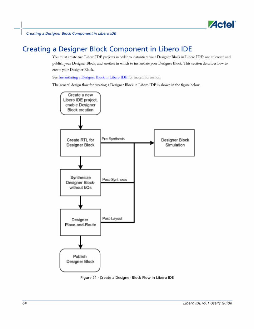
Creating a Designer Block Component in Libero IDE
64 Libero IDE v9.1 User’s Guide
Creating a Designer Block Component in Libero IDE You must create two Libero IDE projects in order to instantiate your Designer Block in Libero IDE: one to create and publish your Designer Block, and another in which to instantiate your Designer Block. This section describes how to create your Designer Block.
See Instantiating a Designer Block in Libero IDE for more information.
The general design flow for creating a Designer Block in Libero IDE is shown in the figure below.
Figure 21 · Create a Designer Block Flow in Libero IDE
Instantiating a Designer Block in Libero IDE
Libero IDE v9.1 User’s Guide 65
To create a Designer Block in Libero IDE with a new design:
1. Start a new project. You must select a family that supports Block designs (IGLOO, ProASIC3, SmartFusion, Fusion, Axcelerator, and RTAX-S). After your project opens, from the Project menu, choose Settings > Flow, and click the Enable Designer Block creation checkbox.
2. Create a design in Libero IDE (standard design flow - create RTL, synthesize, run place-and-route and generate the block using Designer).
To create a Designer Block in the Libero IDE with an existing design, open your design and from the Project menu, choose Setting > Flow, and click the Enable Designer Block creation checkbox. Note that your design must use a device family that supports Designer Blocks (IGLOO, ProASIC3, SmartFusion, Fusion, Axcelerator, and RTAX-S).
Instantiating a Designer Block in Libero IDE You must have two projects in order to instantiate your Designer Block in Libero IDE: one to create and publish your Designer Blocks, and another in which to instantiate your Designer Block. This topic and the flow shown in the figure below describe how to instantiate your Designer Block in the Libero IDE.
See Creating a Designer Block in Libero IDE for information on how to create a Designer Block. You can also import your Designer Blocks into SmartDesign.

Creating a Designer Block Component in Libero IDE
66 Libero IDE v9.1 User’s Guide
Figure 22 · Libero IDE Designer Block Instantiation Flow
To instantiate (import) a Designer Block in Libero IDE, import your design netlist and CXF file(s). The CXF file imports all the files you need for your Designer Block. After you import your files, the design flow is the same as

Instantiating a Designer Block in Libero IDE
Libero IDE v9.1 User’s Guide 67
regular Libero IDE designs. There is no limit to the number of CXF files you can import, but you cannot import the same Designer Block more than once, and the family and device for your imported block must match your project.
After you import the CXF file, the Project Manager displays the imported files in the Design Hierarchy tab.
The Designer Block(s) you instantiate must have the same family and die (and package, if it contains I/Os) as your current <top> project. If the family, die, and package do not match, Libero IDE asks if you want to change the current setting to match the one from the Designer Block.
The Project Manager passes all the Designer Block files to Designer automatically.
Note: Note
• Disable Designer Block creation when you import a component into your <top> project. If you are using a Designer Block component to create another Designer Block, leave it enabled.
• If you already have an HDL component with the same name as the one you imported, the new Designer Block component is not be used by default. You must and right-click the Designer Block component in the Project Manager and choose Use this file to make it use your Designer Block.
Creating a Designer Block Component in Designer
68 Libero IDE v9.1 User’s Guide
Creating a Designer Block Component in Designer
To create a Designer Block component in Designer, start a new design, and Enable Designer Block creation in the Setup Design dialog box. You must select a family that supports Designer Blocks.
You cannot create a Designer Block after you start a new design; you must create a new design and Enable Designer Block creation at the start.
To create a new design and Enable Designer Block creation using a script, use the command string:
new_design -name "test" -family "ProASIC3" -path {.} -block "ON"
After you create your new Designer Block, proceed as usual.
1. Import your source and auxiliary file(s)
2. Compile your design
3. Run Layout to place-and-route your design
4. Back-Annotate your design (if necessary)
5. Publish your Designer Block
Designer Block Component PDC Commands
Creating a Block The Designer-Block specific PDC command set_port_block enables you to remove an I/O connected to a component port and add a buffer before or after a component port to limit the fanout of the port net. The command applies only to the selected port.
The tribuf and bibuf I/Os cannot be removed.
Adding a buffer enables more precise Designer Block timing, since the nets driving ports are not preserved when the Designer Block is generated/published.
Instantiating a Block The following PDC commands manage conflict resolution between blocks. Each command is specific to an instance of a block.
• move_block - Moves Designer Blocks from their original locked placement by preserving the relative placement between the instances. You can move them left, right, up or down.

Floorplanning a Designer Block
Libero IDE v9.1 User’s Guide 69
• set_block_options - Overrides the compile option for placement or routing conflicts for either a specific block or an instance of a block.
Floorplanning a Designer Block Actel recommends that you floorplan your Designer Block component (in MVN or with PDC commands) to ensure that your Designer Block is placed in a specific region. If you do not restrict your Designer Block placement, it may be placed anywhere on your die; see the define_region PDC command.
It is also important to consider the placement of all interface macros in the boundaries of these regions. This facilitates the interconnection of the Designer Block to the top-level design. If the Designer Block is highly optimized (densely packed) there may be no routing channels available to connect to any internal Designer Block interface macro. Placing all interfaces at Designer Block boundaries helps you eliminate routability issues, routing congestion, and failure.
Designer-Block specific features in MVN are:
• Block Ports tab - Lists all the ports in a Designer Block even if they are not connected to I/Os.
• Interface Instances in Designer Block creation (in the Active Lists) - Lists all macros connected to ports. These macros must be placed on the boundary of your Designer Block region, since they will be connected to the <top> design.
• Designer Block content available when you instantiate a Designer Block in the <top> design (in Active Lists) - Lists all macros in the Designer Block.
• A block tab that lists all the blocks in your design.
• Search support that enables you to find a specific block in your design.
• Show the routing of locked nets from the Designer Blocks immediately after compile is complete; no need to wait until layout is finished since the routing is locked and will not be changed.
Generate a Designer Block Component in Designer When you finish Compile and Layout, click Generate Block to create your Designer Block files.
When you publish your Designer Block, Designer creates a netlist file (*.v; *.vhd), info file for Libero IDE (*.cxf), Designer Block file (*.cdb), and report files.
Libero IDE uses the CXF file to manage and audit the Designer Block in your project. The CDB file contains all your design information for the Designer Block.
You can edit your Designer Block later; just open the design, make your changes, and re-create.

Creating a Designer Block Component in Designer
70 Libero IDE v9.1 User’s Guide
Figure 23 · Generate Designer Block Files Dialog Box
Designer Block name - Specifies the name of all your exported files. The exported Designer Block files in this example are named block_test.cxf, block_test.cdb, and block_test_syn.v and block_test_sim.v (block_test_syn.vhd and block_test_sim.vhd for VHDL).
Location - Specifies the location of your exported Designer Block files. Click the Browse button to navigate if you do not know the full pathname.
Options
Generates (exports) your Netlist, Placement, Routing, and Region information. The options available depend on whether you ran place-and-route, placer only, or compile.
Netlist - Always published by default. You cannot deselect this option.
Placement - Available only if you have already run place. This option fixes the internal block elements so they will not move after you import them in your <top> design. Select this option if you are satisfied with the current placement of your block.
Routing - Available if you run place-and-route and opt to preserve Placement. This option fixes your place-and-route and ensures that your block timing does not change in your <top> design.
Region - Exports the regions (if any) you used when you created your block. Useful if you use an exclusive region on top of your Designer Block. You can delete these regions in your <top> design.

Generate a Designer Block Component in Designer
Libero IDE v9.1 User’s Guide 71
The only recommended use case for this option is when you add an exclusive region on top of your block. Actel recommends you leave this option unselected for all other cases.
Language - Specify your export language.
Comment - Add a comment to your exported files (visible in Designer in the Block report available in Tools > Reports > Block).
See Also export Designer Block Tcl command

Instantiating a Designer Block Component in Designer
72 Libero IDE v9.1 User’s Guide
Instantiating a Designer Block Component in Designer
To instantiate (import) a Designer Blocks into a design:
1. Open your design.
2. Deselect Enable Designer Block creation in the Setup Design dialog box.
3. Import your netlist (*.v, *.vhd, or EDIF file) and CDB files from your component. The CDB file is created when you publish your component.
If you have no I/Os, the imported Designer Block must have the same family and die as your current design.
If you have I/Os in your Designer Blocks, the imported block must have the same family, die, and package as your current design.
Note: Note: IGLOO, ProASIC3, SmartFusion and Fusion families ONLY - Blocks that contain only COREs and RAM/FIFOs can be instantiated in a design belonging to any family and die.
Exporting an Instantiated Designer Block Component You can export component CDB files after you instantiate (import) them into your design.
You may wish to reuse the files in another design, or rerun the flow again.
To export a CDB file, from the File menu, choose Export > Netlist Files and for the Save as type, choose Actel CDB files (*.cdb). The exported CDB file is identical to the original imported CDB file.
If you export a Designer Block that contains multiple CDB files, the exported files are identical to the original imported CDB files.
If your design contains many CDB files, the block name is added as a suffix to the specified filename; the names of all exported files are listed in the Log window. For example:
Wrote to files:
E:\block\dblock.cdb
E:\block\dblock_core2.cdb
Conflict Resolution in Designer Blocks If you instantiate more than one block in your design, you may have a conflict between the blocks. Designer manages conflicts between blocks according to the following priority:
1. CDB file order (as specified in the CDB File Organization dialog box in the Project Manager). You can change this order in Designer; to do so, from the File menu, choose Import Source Files.

Conflict Resolution in Designer Blocks
Libero IDE v9.1 User’s Guide 73
2. Compile options set to resolve place-and-route conflicts between blocks (see below for a full explanation of the Block Instantiation compile options)
3. PDC options (set_block_options and move_block)
You can review the results of the conflict resolution in the Compile report and in the Block tab in MVN.
Block Instantiation Compile Options If there multiple blocks instantiated in your design, Designer uses the Compile options to resolve the conflicts.
Placement
Value Description
ERROR Compile errors out if any instance from a designer block is unplaced. This is the default option.
RESOLVE If some instances get unplaced for any reason, the remaining non-conflicting elements are unplaced. In other words, if there are any conflicts, nothing from the block is kept.
KEEP If some instances get unplaced for any reason, the non-conflicting elements remaining are preserved but not locked (you can move them).
LOCK If some instances get unplaced for any reason, the remaining non-conflicting elements are preserved and locked.
Routing
Value Description
ERROR Compile errors out if any preserved net routing in a designer block is deleted.
RESOLVE If a nets' routing is removed for any reason, the routing for non-conflicting nets is also removed. In other words, if there are any conflicts, no routing from the block is kept
KEEP If a nets routing is removed for any reason, the routing for the non-conflicting nets is preserved but not locked (so that they can be rerouted).
LOCK If the routing is removed for any reason, the remaining non-conflicting nets are

Instantiating a Designer Block Component in Designer
74 Libero IDE v9.1 User’s Guide
Value Description
preserved and locked; they cannot be rerouted. This is the default option.
Designer Block Report The Designer Block report is available in Tools > Reports > Block. It includes a compile, global, datasheet, and interface report and Designer Block-related information.
The block reports are available in the Project Manager Files tab after you generate your block and instantiate it in your project. Double-click the report to view the contents.
In the Project Manager there is a header_report.log that contains only the options used to generate the block. This information is available in each report you generate from the Designer > Tools menu.
Compile Use it to evaluate resources and manage the globals in the other blocks and the <top> design (if necessary).
Datasheet Lists block timing and I/O placement information. If the block is preserved during instantiation (both placement and routing) you can expect to get the same results as are shown in this report.
Global Lists global usage in the block. Useful if you want to evaluate the globals used by the block / manage globals in the overall design.
Interface The Interface section lists:
• Connection information for interface macros connected to the block ports
• Block placement information, including each port and its fanout, type (pad, clock, global, etc.), direction, and name
• Information on legal move locations, useful if you are instantiating multiple blocks in one design

About SmartDesign
Libero IDE v9.1 User’s Guide 75
SmartDesign
About SmartDesign SmartDesign is a revolutionary innovation for creating and managing block-based designs. SmartDesign enables you to take configured cores, IP cores, and macros from a Project Manager Catalog, and user-created HDL source files, and instantiate them into your design. SmartDesign displays your design in multiple views enabling you to access and manipulate your design quickly and efficiently.
You can drag configured cores onto a Canvas where they are viewed as blocks in a functional block diagram. From the Canvas you can:
• Make connections between your blocks
• View individual connection details
• Show or hide individual nets
• Set or clear attributes (such as Invert, Tie Low, Tie High, or Tie Open)
• Add slices
• Move, duplicate, or delete blocks
• Add notations such as labels, shapes, lines, or arrows to document your design
• Auto-stitching interfaces and other connections (such as AMBA)
• Memory Map / Datasheet - The datasheet reports the memory map of the different subsystems of your design, where a subsystem is any independent bus structure with a Master and Slave peripheral attached.
SmartDesign supports all Actel product families.
SmartDesign Design Flow SmartDesign enables you to stitch together design blocks of different types (HDL, IP, etc ) and generate a top-level design. The Files tab lists your SmartDesign files in alphabetical order.
You can build your design using SmartDesign with the following steps:
Step One – Instantiating components: In this step you will add one or more building blocks, HDL modules, components, and schematic modules from the project manager to your design. The components can be Designer blocks, cores generated from the core Catalog, and IP cores.
Step Two – Connecting bus interfaces: In this step, you can add connectivity via standard bus interfaces to your design. This step is optional and can be skipped if you prefer manual connections. Components generated from the Catalog in Project Manager may include pre-defined interfaces that allow for automatic connectivity and design rule checking when used in a design.
SmartDesign
76 Libero IDE v9.1 User’s Guide
Step Three – Connecting instances: The Canvas allows you to create manual connections between ports of the instances in your design. Unused ports can be tied off to GND or VCC (disabled); input buses can be tied to a constant, and you can leave an output open by marking it as unused.
Step Four – Validating the SmartDesign component: Verify the connectivity of your design using the Design Rules Check. This feature opens a special grid where design errors and warnings are organized by type and message. You can fix the errors and warnings directly in the grid. You must run the Design Rules Check again after you make your connections to check for new errors and warnings.
Step Five – Generating the SmartDesign component: In this step, you generate a top-level (Top) component and its corresponding HDL file. This component can be used by downstream processes, such as synthesis and simulation, or you can add your SmartDesign HDL into another SmartDesign.
You can save your SmartDesign at any time.
Using Existing Projects with SmartDesign You can use existing Libero® Integrated Design Environment (IDE) projects with available building blocks in the project to assemble a new SmartDesign design component. You do not have to migrate existing top-level designs to SmartDesign and there is no automatic conversion of the existing design blocks to the SmartDesign format.
Note: Note: Cores used in previous versions of software will work in SmartDesign, but they will NOT include standard bus interfaces if they are available. Bus interfaces (BIFs) can be recovered by regenerating the core in the latest software.
Note: Examples of cores with standard BIFs: ASB, Flash Memory System Builder, VRPSM, AMBA DirectCore(s), and similar.
SmartDesign Frequently Asked Questions The collection of SmartDesign Frequently Asked Questions are useful for anyone that is new to SmartDesign. All the information listed below is explained in detail in other sections of the help, but the information is summarized here for easy reference. Click any question to go to the corresponding explanation.

SmartDesign Frequently Asked Questions
Libero IDE v9.1 User’s Guide 77
General Questions 1. What is SmartDesign?
2. How do I create my first SmartDesign?

SmartDesign
78 Libero IDE v9.1 User’s Guide
Instantiating your SmartDesign 1. Where is the list of cores that I can instantiate into my SmartDesign?
2. How do I instantiate cores into my SmartDesign?
3. I have a block that I wrote in VHDL (or Verilog), can I use that in my SmartDesign?
Working in SmartDesign 1. How do I make connections?
2. Auto Connect didn’t connect everything for me; how do I make manual connections?
3. How do I connect a pin to the top level?
4. Oops, I just made a connection mistake. How do I disconnect two pins?
5. I need to apply some simple ‘glue’ logic between my cores. How do I do that?
6. My logic is a bit more complex than inversion and tie offs - what else can I do?
7. How do I create a new top level port for my design?
8. How do I rename one of my instances?
9. How do I rename my top level port?
10. How do I rename my group pins?
11. I need to reconfigure one of my Cores, can I just double click the instance?
12. I want more Canvas space to work with!

Working in SmartDesign
Libero IDE v9.1 User’s Guide 79
Working with Processor-Based Designs in SmartDesign 1. How do I connect my peripherals to the bus?
2. How do I view the Memory Map of my design?
3. How do I simulate my processor design?
4. I have my own HDL block that I want to connect as a peripheral on the AMBA bus. How can I do that?

SmartDesign
80 Libero IDE v9.1 User’s Guide
Making your Design Look Nice 1. Can the tool automatically place my instances on the Canvas to make it look nice?
2. My design has a lot of connections, and the nets are making my design hard to read. What do I do?
3. My instance has too many pins on it, how can I minimize that?
4. Oops, I missed one pin that needs to be part of that group? How do I add a pin after I already have the group?
5. I have a pin that I don’t want inside the group, how do I remove it?
6. How can I better see my design on the Canvas?

Working in SmartDesign
Libero IDE v9.1 User’s Guide 81
Generating your Design 1. Ok, I’m done connecting my design, how do I ‘finish’ it so that I can proceed to synthesis?
2. I get a message saying it’s unable to generate my SmartDesign due to errors, what do I do? What is the Design Rules Check?
3. Is there an easy way for me to tie off multiple pins at once?
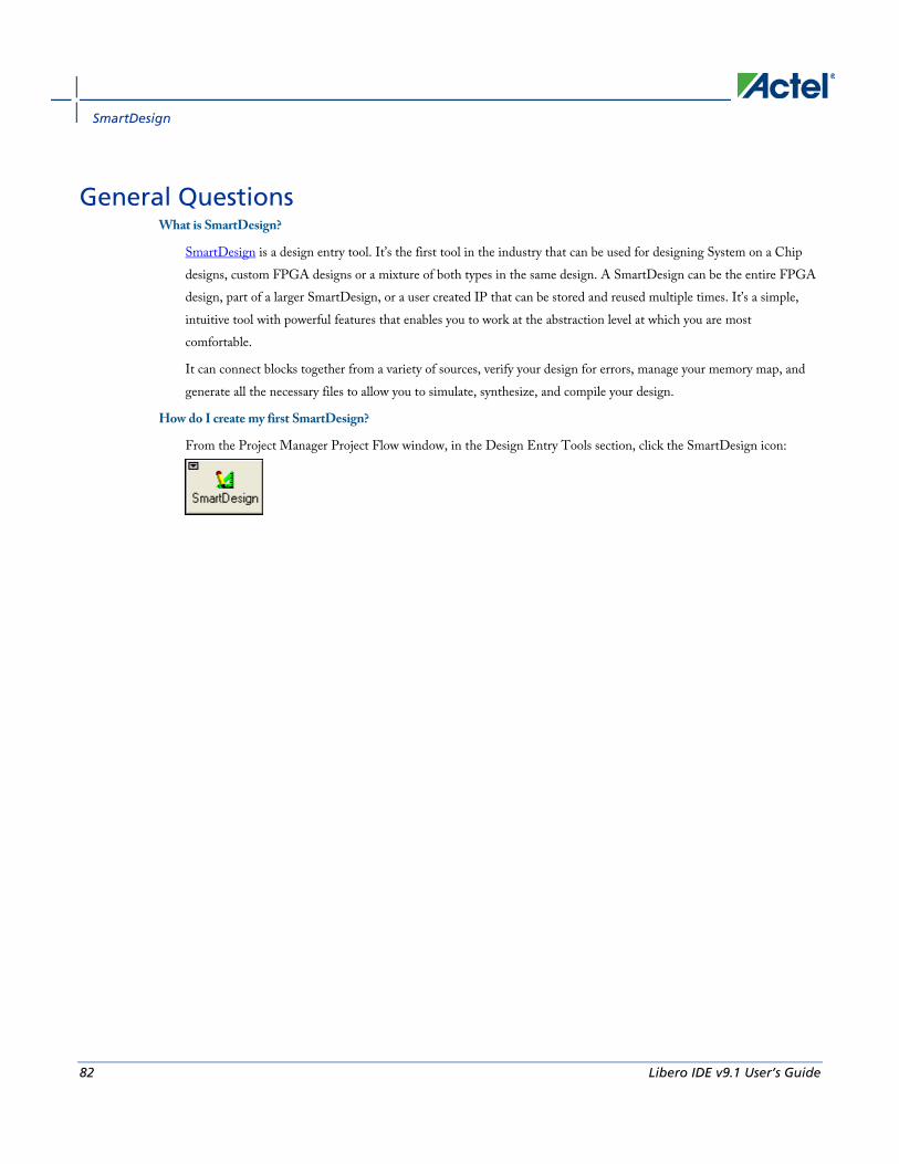
SmartDesign
82 Libero IDE v9.1 User’s Guide
General Questions What is SmartDesign?
SmartDesign is a design entry tool. It’s the first tool in the industry that can be used for designing System on a Chip designs, custom FPGA designs or a mixture of both types in the same design. A SmartDesign can be the entire FPGA design, part of a larger SmartDesign, or a user created IP that can be stored and reused multiple times. It’s a simple, intuitive tool with powerful features that enables you to work at the abstraction level at which you are most comfortable.
It can connect blocks together from a variety of sources, verify your design for errors, manage your memory map, and generate all the necessary files to allow you to simulate, synthesize, and compile your design.
How do I create my first SmartDesign?
From the Project Manager Project Flow window, in the Design Entry Tools section, click the SmartDesign icon:

Working in SmartDesign
Libero IDE v9.1 User’s Guide 83
Instantiating Your SmartDesign Where is the list of Cores that I can instantiate into my SmartDesign?
The list of available cores is displayed in the Project Manager Catalog. This catalog contains all DirectCore IP, Design Block cores, and Actel macros.
How do I instantiate cores into my SmartDesign?
Drag and drop the core from the Catalog onto your SmartDesign Canvas. The configurator for that core opens automatically. Choose your configurations, click OK, and an instance of your core appears on the SmartDesign Canvas.
I have a block that I wrote in VHDL ( or Verilog ), can I use that in my SmartDesign?
Yes! Import your HDL file into the Project Manager (File > Import Files). After you do this, your HDL module will appear in the Project Manager Hierarchy. Then, drag-and-drop it from the Hierarchy onto your SmartDesign Canvas.
Working in SmartDesign How do I make connections?
Let SmartDesign do it for you. Right-click the Canvas and choose Auto Connect.
Auto Connect didn’t connect everything for me, how do I make manual connections?
1. Select the pins you want connected by using the mouse and the CTRL key.
2. Right-click one of the selected pins and choose Connect.
3. For bus interface pins you can do the same thing, OR: Right click a bus interface pin, choose Find Compatible Bus Interfaces. A dialog box will display a list of the compatible bus interfaces in the design that you can connect to. Choose the bus interface you want to connect to from the list and click OK.
How do I connect a pin to the top level?
Right-click the pin and choose Promote to Top Level. You can even do this for multiple pins at a time, just select all the pins you want to promote, right-click one of the pins and choose Promote to Top Level. All your selected pins will be promoted to the top level.
Oops, I just made a connection mistake. How do I disconnect two pins?
Use CTRL+Z to undo your last action. If you want to undo your ‘undo’, hit redo (CTRL+Y).
To disconnect pins you can:
• Right-click the pin you want to disconnect and choose Disconnect
• Select the net and hit the delete key
I need to apply some simple ‘glue’ logic between my cores. How do I do that?

SmartDesign
84 Libero IDE v9.1 User’s Guide
For basic inversion of pins, you can right-click a pin and choose Invert. An inverter will be placed at this pin when the design is generated. You can also right-click a pin and choose Tie Low or Tie High if you want to connect the pin to either GND or VCC.
To tie an input bus to a constant, right-click the bus and choose Tie to Constant. To mark an output pin as unused, right-click the pin and choose Mark as Unused.
To clear these, just right-click on the pin again and choose Clear Attribute.
My logic is a bit more complex than inversion and tie offs - what else can I do?
You have full access to the Actel library macros, including AND, OR, and XOR logic functions. These are located in the Project Manager Catalog, listed under Actel Macros. Drag the logic function you want onto your SmartDesign Canvas.
How do I create a new top level port for my design?
You can right-click either of the top level blocks (gray blocks on the left and right of the Canvas space). Right-click the block on the far left of your Canvas (this represents the top level of your design) and choose Add Port.
How do I rename one of my instances?
Double-click the instance name on the Canvas and it will become editable. The instance name is located directly above the instance on the Canvas.
How do I rename my top level port?
Right-click the port you want to rename and choose Modify Port.
How do I rename my group pins?
Double-click the group pin name in the instance and it will become editable.
I need to reconfigure one of my Cores, can I just double click the instance?
Yes.
I want more Canvas space to work with!
Maximize your workspace (CTRL-W), and your Canvas will maximize within the Project Manager. Hit CTRL-W again if you need to see your Hierarchy or Catalog.

Working in SmartDesign
Libero IDE v9.1 User’s Guide 85
Working with Processor-Based Designs in SmartDesign How do I connect my peripherals to the bus?
Make sure you have the proper bus core that is compatible with your peripheral instantiated in the design. Click Auto Connect and SmartDesign will automatically form the connections.
But I need my peripheral at a specific address or slot.
Right-click the Canvas and choose Modify Memory Map to invoke the Modify Memory Map dialog that enables you to set a peripheral to a specific address on the bus.
The bus core will show the slot numbers on the bus interface pins. These slot numbers correspond to a memory address on the bus.
Verify that your peripheral is mapped to the right bus address by viewing your design’s Memory Map.
How do I view the Memory Map of my design?
In the Project Manager menu bar, choose SmartDesign > Show Memory Map/Data Sheet. This creates a datasheet of your design, including the pin out, cores used, and memory map.
The memory map section will also show the memory details of each peripheral, including any memory mapped registers.
How do I simulate my processor design?
SmartDesign automatically generates the necessary Bus Functional Model (BFM) scripts required to simulate your processor based design. A top level testbench for your SmartDesign is generated automatically as well.
Create your processor design, generate it, and you will be able to simulate it in ModelSim.
I have my own HDL block that I want to connect as a peripheral on the AMBA bus. How can I do that?
If your block has all the necessary signals to interface with the AMBA bus protocol ( ex: address, data, control signals) then:
1. In the Project Manager Catalog (inside the Bus Definitions tab), find the AHB or APB slave interface.
2. Drag this bus definition onto your instance on the Canvas. A dialog box opens, asking you to map the signals on your instance to the required bus definition signals. Complete this mapping and click OK.
Now your instance has a proper AMBA bus interface on it. You can manually connect it to the bus or let Auto Connect find a compatible connection.

SmartDesign
86 Libero IDE v9.1 User’s Guide
Making your Design Look Nice Can the tool automatically place my instances on the Canvas to make it look nice?
Yes. Right-click the Canvas white space and choose Auto Arrange Instances.
My design has a lot of connections, and the nets are making my design hard to read. What do I do?
You can disable the display of the nets in the menu bar (Canvas > Nets). This automatically hides all the nets in your design.
You can still see how pins are connected by selecting a connected pin, the net will automatically be visible again.
You can also selectively show certain nets, so that they are always displayed, just right click on a connected pin and choose Show Net.
My instance has too many pins on it; how can I minimize that?
Try grouping functional or unused pins together. For example, on the CoreInterrupt there are 8 FIQSource* and 32 IRQSource* pins, group these together since they are similar in functionality.
To group pins: Select all the pins you want to group, then right-click one of the pins and choose Add pins to group.
If a pin is in a group, you are still able to use it and form connections with it. Expand the group to gain access to the pin.
Oops, I missed one pin that needs to be part of that group? How do I add a pin after I already have the group?
Select the pin you want to add and the group pin, right-click and choose Add pins to <name> group.
I have a pin that I don’t want inside the group, how do I remove it?
Right-click the pin and choose Ungroup selected pins.
How can I better see my design on the Canvas?
There are zoom icons in the toolbar:
From left to right, they are: Zoom in, Zoom out, Zoom to fit, and Zoom range. You can also maximize your workspace with CTRL-W.
Generating your Design Ok, I’m done connecting my design, how do I ‘finish’ it so that I can proceed to synthesis?
In the Project Manager toolbar, click the Generate Design icon or right-click the Canvas and choose Generate Design.
I get a message saying it’s unable to generate my SmartDesign due to errors, what do I do? What is the Design Rules Check?

Generating your Design
Libero IDE v9.1 User’s Guide 87
In the Project Manager toolbar, click the Design Rules Check icon:
The Design Rules Check will give you a list of all the errors and warnings in your design, including unconnected input pins, required pin connections, configuration incompatibilities between cores, etc.
Errors are shown with a small red stop sign and must be corrected before you can generate; warnings may be ignored.
What does this error mean? How do I fix it?
Review the Design Rules Check topic for an explanation of errors in the Design Rules Check and steps to resolve them.
Is there an easy way for me to tie off multiple pins at once?
Yes, if you are in the Design Rules Check grid, you can select multiple pins by highlighting the rows that they are in. Multi-selecting works just like your typical spreadsheet editor.
Once all the pins have been selected, right-click one of the pin names and choose Tie Low or Tie High. Make sure you only have input pins selected otherwise the menu item won’t be enabled.
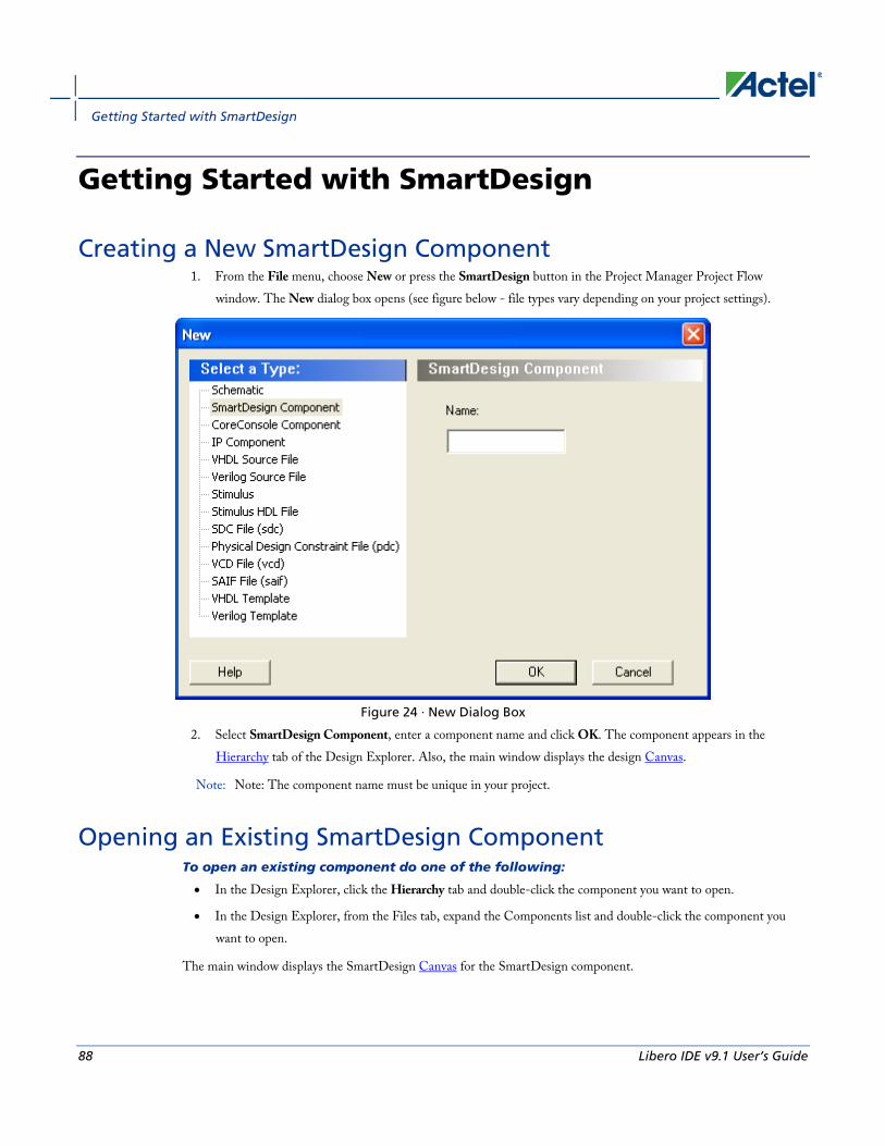
Getting Started with SmartDesign
88 Libero IDE v9.1 User’s Guide
Getting Started with SmartDesign
Creating a New SmartDesign Component 1. From the File menu, choose New or press the SmartDesign button in the Project Manager Project Flow
window. The New dialog box opens (see figure below - file types vary depending on your project settings).
Figure 24 · New Dialog Box
2. Select SmartDesign Component, enter a component name and click OK. The component appears in the Hierarchy tab of the Design Explorer. Also, the main window displays the design Canvas.
Note: Note: The component name must be unique in your project.
Opening an Existing SmartDesign Component To open an existing component do one of the following:
• In the Design Explorer, click the Hierarchy tab and double-click the component you want to open.
• In the Design Explorer, from the Files tab, expand the Components list and double-click the component you want to open.
The main window displays the SmartDesign Canvas for the SmartDesign component.

Saving/Closing a SmartDesign Component
Libero IDE v9.1 User’s Guide 89
Saving/Closing a SmartDesign Component To save the current SmartDesign design component, from the File menu, choose Save <component_name>. Saving a SmartDesign component only saves the current state of the design; to generate the HDL for the design refer to Generating a SmartDesign component.
To close the current SmartDesign component without saving, from the File menu, choose Close. Select NO when prompted to save.
To save the active SmartDesign component with a different name use Save As. From the File menu choose Save SD_<filename> As. Enter a new name for your component and click OK.
You can also close a SmartDesign component by right-clicking the name of the SmartDesign tab in the work area window and choosing Close, as in the figure below.
Figure 25 · Close a SmartDesign
Importing a SmartDesign Component Importing an existing SmartDesign component into a SmartDesign project will not automatically import the sub-components of that imported SmartDesign component.
You must import each sub-component separately.
After importing the sub-components, you must open the SmartDesign component and replace each sub-component so that it references the correct component in your project. .
Deleting a SmartDesign Component from the Libero IDE Project
To delete a SmartDesign component from the project:
1. In the Design Explorer, click the Hierarchy tab.
2. Select the SmartDesign component that you want to delete. Right-click the component name and select Delete from Project or Delete from Disk and Project, or click the Delete key to delete from project.
Memory Maps / Data Sheet If your design contains standard Bus Instances such as the DirectCore AMBA bus cores, CoreAPB or CoreAHB, then you can view the Memory Map Configuration of your design. To do so, from the SmartDesign menu, choose Show Memory Map / Data Sheet.
The design’s memory map is determined by the connections made to the bus component. A bus component is divided into multiple slots for slave peripherals or instances to plug into. Each slot represents a different address location and range to the Master of the bus component.

Getting Started with SmartDesign
90 Libero IDE v9.1 User’s Guide
The datasheet reports the memory map of the different subsystems of your design, where a subsystem is any independent bus structure with a Master and Slave peripheral attached.
Connecting peripherals to busses can be accomplished using the normal SmartDesign connectivity options:
• Auto-Connect - the system finds compatible bus interfaces and connects them together
• The Modify Memory Map dialog box
• Canvas - Make connections between your blocks.
• Finding compatible bus interfaces
Your application and design requirements dictate which address location (or slots) is most suitable for your bus peripherals. For example, the memory controller should be connected to Slot0 of the CoreAHB bus because on Reset, the processor will begin code execution from the bottom of the memory map.
The Memory Map View opens your default web browser to display the memory map information. An example is shown in the figure below.
Figure 26 · Example Memory Map
Modify Memory Map Dialog Box
Libero IDE v9.1 User’s Guide 91
Modify Memory Map Dialog Box The Modify Memory Map dialog box (shown in the figure below) enables you to connect peripherals to buses via a drop-down menu. To open the dialog box, right-click on the Canvas or specific bus instance and choose Modify Memory Map.
This dialog simplifies connecting peripherals to specific base addresses on the bus. The dialog shows all the busses in the design; select a bus in the left pane to assign or view the peripherals on a bus. Busses that are bridged to other busses are shown beneath the bus in the hierarchy.
Figure 27 · Modify Memory Map Dialog Box
Click the Peripheral drop-down menu to select the peripheral you wish to assign to each address. To remove (unassign) a peripheral from an address, click the drop-down and select the empty element.
Click OK to create the connections between the busses and peripherals in the design.
Finding Ports/Nets/Instances in SmartDesign Use the Find Window to search for ports, nets, or instances in SmartDesign.
Searching for ports / nets / instances in SmartDesign highlights the objects on the Canvas.
Convert CoreConsole Components Your project contains components that were created by CoreConsole. CoreConsole is being replaced by SmartDesign, which incorporates the same functionality with enhanced features.
Actel recommends that you upgrade and convert your design.
The converted SmartDesign and/or IP Component is fully equivalent in terms of peripheral configuration and connectivity. In addition, your instance, port, and net names are preserved.
When you transition to SmartDesign, your CoreConsole design is converted to a SmartDesign and opened on the SmartDesign Canvas. You must regenerate your SmartDesign component after you transition from CoreConsole.

Getting Started with SmartDesign
92 Libero IDE v9.1 User’s Guide
Converting your component requires a re-synthesis of your design. If you have already completed your design and validation phase and are satisfied with your design then you can choose to continue using CoreConsole.
In SmartDesign you can drag configured cores onto the Canvas where they are viewed as blocks in a functional block diagram. From the Canvas you can:
• Make connections between your blocks
• Easily instantiate and connect HDL, Design Block (non-IP Catalog cores), and Actel macros
• View individual connection details
• Show or hide individual nets
• Set or clear attributes (such as Invert, Tie Low, Tie High, or Tie Open)
• Add slices
• Move, duplicate, or delete blocks
• Add notations such as labels, shapes, lines, or arrows to document your design
• Auto-stitching interfaces and other connections (such as AMBA)
• Memory Map / Datasheet - The datasheet reports the memory map of the different subsystems of your design, where a subsystem is any independent bus structure with a Master and Slave peripheral attached.
In certain situations, conversion may not produce a fully equivalent design. In this case, the following message appears in the log window:
Warning: A bus interface ‘<bus interface>’ was found at the top level of component ‘<design>’, the converted design may have different top level ports related to this bus interface. Please check your converted design.
This occurs because CoreConsole and SmartDesign have different rules when connecting bus interfaces to the top level. The design is still functionally the same, except it may have differently named ports related to that bus interface and you may have extra ports related to that bus interface. The extra ports are due to the fact that SmartDesign creates unique output ports in the bus interface even if they are connected to the same pin internally.
See the SmartDesign FAQ for more information on basic operations in CoreConsole and their SmartDesign equivalent. SmartDesign also has specific support for working with processor-based designs.
What to do if Conversion Fails If core(s) contained in the CoreConsole project are not downloaded into your vault: You must download these cores into your vault and rerun the conversion. See the Catalog help topic for more information on downloading cores.
If core(s) contained in the CoreConsole project are using the legacy IP-XACT loose generator interface (LGI) that is no longer supported: Once the new versions of these cores are available, you can substitute the new version in your CoreConsole project and rerun the conversion. To rerun the conversion, close and reopen your Libero IDE project.

Convert CoreConsole Components
Libero IDE v9.1 User’s Guide 93
Restore CoreConsole Components If you converted your project by mistake you can restore your pre-converted CoreConsole component. Your original unconverted CoreConsole component is saved in a ZIP file in the Libero IDE project folder. The saved component is saved as <project>\coreconsole\<name>_backup.zip
To restore your CoreConsole components:
1. Delete the SmartDesign component from disk and project. Right-click the component and choose Delete from Disk and Project.
2. In Windows Explorer, navigate to the CoreConsole folder in your Libero IDE project folder. Double-click your component and unzip it to the local directory.
3. Import your unconverted CoreConsole project (CXF file) back into the Libero IDE. In the Project Manager, from the File menu, choose Import Files and select Components (*.cxf) as the file type. Navigate to your unzipped CoreConsole component to select and Import.
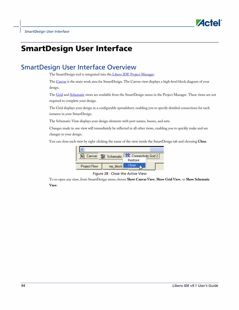
SmartDesign User Interface
94 Libero IDE v9.1 User’s Guide
SmartDesign User Interface
SmartDesign User Interface Overview The SmartDesign tool is integrated into the Libero IDE Project Manager.
The Canvas is the main work area for SmartDesign. The Canvas view displays a high-level block diagram of your design.
The Grid and Schematic views are available from the SmartDesign menu in the Project Manager. These views are not required to complete your design.
The Grid displays your design in a configurable spreadsheet, enabling you to specify detailed connections for each instance in your SmartDesign.
The Schematic View displays your design elements with port names, busses, and nets.
Changes made in one view will immediately be reflected in all other views, enabling you to quickly make and see changes to your design.
You can close each view by right-clicking the name of the view inside the SmartDesign tab and choosing Close.
Figure 28 · Close the Active View
To re-open any view, from SmartDesign menu choose Show Canvas View, Show Grid View, or Show Schematic View.

Canvas Overview
Libero IDE v9.1 User’s Guide 95
Canvas View
Canvas Overview The SmartDesign Canvas is like a whiteboard where functional blocks from various sources can be assembled and connected; interconnections between the blocks represent nets and busses in your design.
You can use the Canvas to manage connections, set attributes, add or remove components, etc. The Canvas displays all the pins for each instance (as shown in the figure below).
The Canvas enables you to drag a component from the Hierarchy, Files list, or a core from the Catalog and add an instance of that component or core in the design. Some blocks (such as Basic Blocks) must be configured and generated before they are added to your Canvas. When you add/generate a new component it is automatically added to your Hierarchy.
To connect two pins on the Canvas, select any two pins on the Canvas (Ctrl + click to select a pin), right-click one of the pins you selected and choose Connect. The Connect is disabled if you attempt to illegally connect two pins.
Click the Maximize Work Area button to hide the other windows and show more of the Canvas. Click the button again to return the work area to the original size.
The Canvas displays bus pins with a + sign (click to expand the list) or - (click to hide list). If you add a slice on a bus the Canvas adds a + to the bus pin.
Components can be reconfigured any time by double-clicking the instance on the Canvas. You can also add bus interfaces to instances using this view. In the Canvas view, you can add graphic objects and text to your design.
Inputs and bi-directional pins are shown on the left of components, and output pins are shown on the right.
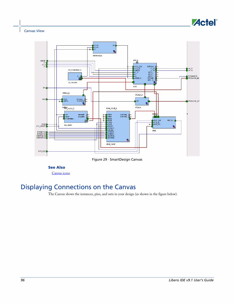
Canvas View
96 Libero IDE v9.1 User’s Guide
Figure 29 · SmartDesign Canvas
See Also Canvas icons
Displaying Connections on the Canvas The Canvas shows the instances, pins, and nets in your design (as shown in the figure below).

Displaying Connections on the Canvas
Libero IDE v9.1 User’s Guide 97
Figure 30 · Components in SmartDesign
Scalar net connections are shown in blue; bus net connections are dark blue.
Undriven nets are indicated by a blue dotted line.
Pin and Attribute Icons Unconnected pins that do not require a connection are gray.
Unconnected pins that require a connection are red.
Unconnected pins that have a default tie-off are pale green.
Connected pins are green.
Right-click a pin to assign an attribute.
Pins assigned attributes are shown with an icon, as shown in the table below.
Table 3 · Pin Attribute Icons
Attribute Icon
Tie Low
Tie High

Canvas View
98 Libero IDE v9.1 User’s Guide
Attribute Icon
Invert
Mark as Unused
See the Canvas Icons reference page for definitions for each element on the Canvas.
Each connection made using a bus interface is shown in a separate connection known as a 'bus-interface net' (shown in brown lines).
Move the mouse over a bus interface to display its details (as shown below).
Hover over a bus interface net to see details (as shown below).
Making Connections Using the Canvas Use the Canvas to make connections between instances.
To connect two pins on the Canvas, select any two (Ctrl + click to select a pin), right-click one of the pins you selected and choose Connect. Illegal connections are disabled; the Connect menu option is unavailable.
Promoting Ports to Top Level To automatically promote a port to top level, select the port, right-click, and choose Promote To Top Level. This automatically creates top-level ports of that name and connects the selected ports to them. If a port name already exists, a choice is given to either connect to the existing ports or to create a new port with a name <port name>_<i> where i = 1…n.
Double-click a top-level port to rename it.

Simplifying the Display of Pins on an Instance using Pin Groups
Libero IDE v9.1 User’s Guide 99
Bus slices cannot be automatically promoted to top level. You must create a top level port of the bus slice width and then manually connect the bus slice to the newly created top level port.
Tying Off Input Pins To tie off ports, select the port, right-click and choose Tie High or Tie Low.
Tying to Constant To tie off bus ports to a constant value, select the port, right-click and choose Tie to a Constant. A dialog appears (as shown in the figure below) and enables you to specify a hex value for the bus.
To remove the constant, right-click the pin and choose Clear Attribute or Disconnect.
Figure 31 · Tie to Constant Dialog Box
Making Driver and Bus Interface Pins Unused Driver or bus interface pins can be marked unused (floating/dangling) if you do not intend to use them as a driver in the design. If you mark a pin as unused the Design Rules Check does not return Floating Driver or Unconnected Bus Interface messages on the pin.
Once a pin is explicitly marked as unused it cannot be used to drive any inputs. The unused attribute must be explicitly removed from the pin in order to connect it later. To mark a driver or bus interface pin as unused, right-click the driver or bus interface pin and choose Mark as Unused.
See Also Exposing Bus Interface Pins
Simplifying the Display of Pins on an Instance using Pin Groups The Canvas enables you to group and ungroup pins on a single instance to simplify the display. This feature is useful when you have many pins in an instance, or if you want to group pins at the top level. Pin groups are cosmetic and affect only the Canvas view; other SmartDesign views and the underlying design are not affected by the pin groups.
Grouping pins enables you to:

Canvas View
100 Libero IDE v9.1 User’s Guide
• Hide pins that you have already connected
• Hide pins that you intend to work on later
• Group pins with similar functionality
• Group unused pins
• Promote several pins to Top Level at once
To group pins:
1. Ctrl + click to select the pins you wish to group. If you try to click-and-drag inside the instance you will move the instance on the canvas instead of selecting pins.
2. Right-click and choose Add pins to group to create a group. Click + to expand a group. The icon associated with the group indicates if the pins are connected, partially connected, or unconnected (as shown in the figure below).
Figure 32 · Groups in an Instance on the Canvas
To add a pin to a group, Ctrl + click to select both the pin and the group, right-click and choose Add pin to group.
To name a group:
To name a group, click the group name on the instance and type in a different name.
To ungroup pins:
1. Click + to expand the group.
2. Right-click the pin you wish to remove from the group and choose Ungroup selected pins. Ctrl + click to select and remove more than one pin in a group.
A group remains in your instance after you remove all the pins. It has no effect on the instance; you can leave it if you wish to add pins to the group later, or you can right-click the group and choose Delete to remove it from your instance.
If you delete a group from your instance any pins still in the group are unaffected.
To promote a group to Top level:
1. Create a group of pins.
2. Right-click the group and choose Promote to Top level.

Bus Instances
Libero IDE v9.1 User’s Guide 101
Bus Instances Bus Components in the Actel Core Catalog, such as CoreAHB or CoreAPB, implement an on-chip bus fabric. When these components are instantiated into your canvas they are displayed as horizontal or vertical lines. Double-click the bus interfaces of your component to edit the connections.
Figure 33 · Bus Instance in SmartDesign
Positioning Busses on the Canvas You may want to adjust the positioning and orientation of a bus on your canvas in order to organize the display of your design.
Rotating Busses Bus instances can be rotated ninety degrees (they must be horizontal or vertical). To rotate a bus instance ninety degrees left or right, right-click the black bar and choose Shape > Rotate Left (or Rotate Right).
Flipping Busses You can flip a bus along the horizontal or vertical axis. To flip a bus, right-click the black bar and choose Shape > Flip Horizontal (or Flip Vertical). Flipping a bus instance along an axis flips ALL the instances directly connected to the bus instance, except those that are connected to another bus instance.
Adding Graphic Objects You can document your design by adding comments and notations directly on the Canvas.
The Canvas toolbar (see figure below) enables you to add and modify decorative graphic objects, such as shapes, labels, lines, and arrows on the Canvas.
Figure 34 · Canvas Toolbar
Adding and deleting lines and shapes To add a line or a shape:
1. Select the line or shape button.
2. Click, drag and release on the Canvas. The table below provides a description of each button.

Canvas View
102 Libero IDE v9.1 User’s Guide
Button Description
Line
Arrow
Rectangle
Ellipse
Note: Hold the Shift key to constrain line and arrow to 45 degree increments or constrain the proportions of the
rectangle (square) or ellipse (circle).
To change the line and fill properties:
1. Select the element(s), right-click it, and choose Properties.
• Select Line to modify the color, style and width of the line.
• Select Fill to modify the crosshatch and the foreground and background colors.
2. Click OK.
To delete a line or shape, select the object and press Delete.
Adding text
To add text, select the text tool and click the Canvas to create a text box. To modify the text, double-click the text box and then type.
To modify the text box properties:
1. Select the text box, right-click it, and choose Properties.
• Select Text to modify the text alignment.
• Select Line to modify the color, style and width of the line.
• Select Fill to modify the crosshatch and the foreground and background colors.
• Select Font to modify the font properties.
2. Click OK.
Adding images To add an image to the canvas:
1. Select the image button . The Open dialog box opens.

Adding Graphic Objects
Libero IDE v9.1 User’s Guide 103
2. Select the image you want to add and click OK.
3. Select the image and place it in the desired location.
Rotating elements Select the element(s) you want to rotate and click the appropriate rotate button. See the table below for a description of each button.
Button Description
Free rotate
Rotate to the left
Rotate to the right
Flipping elements Select the element(s) you want to flip and click the appropriate flip button. See the table below for a description of each button.
Button Description
Flip vertically
Flip horizontally
Aligning elements Select two or more elements on the Canvas and click the appropriate align button. See the table below for a description of each button.
Button Description
Align top
Align middle
Align bottom
Align left

Canvas View
104 Libero IDE v9.1 User’s Guide
Button Description
Align center
Align right
Grouping graphic objects Objects on the Canvas can be grouped and ungrouped.
To group two or more elements, select the elements, right-click, and choose Grouping > Group.
To ungroup two or more elements, select the elements, right-click, and choose Grouping > Ungroup.
Ordering elements (Z-order) Elements on the Canvas can be positioned in front or in back of each other.
To change the order of the element(s), select the element and from the right-click menu, choose Order and select one of the available options: Bring to Front, Send to Back, Bring Forward, or Send Backward.
Auto-arranging Instances The Auto Arrange Instances button arranges the instances on the Canvas. You can also right-click the Canvas and choose Auto Arrange Instances from the right-click menu.
Locking Instance Position You can lock the placement of any instance on the Canvas. Right-click an instance and choose Lock Location to lock the placement. When you lock placement, the Auto Arrange Instances option has no effect on the instance.
To unlock an instance, right-click the instance and choose Unlock Location.
See Also Bus instances
Auto-routing connections
Simplifying the Display of Pins on an Instance using Pin Groups
Auto-arrange Connections The Auto Arrange Connections button arranges the connections between instances. The way connections are drawn is highly dependent on the placement of the instances on the Canvas. The top-level connections are shown connected to the Top Level instance (green boxes).
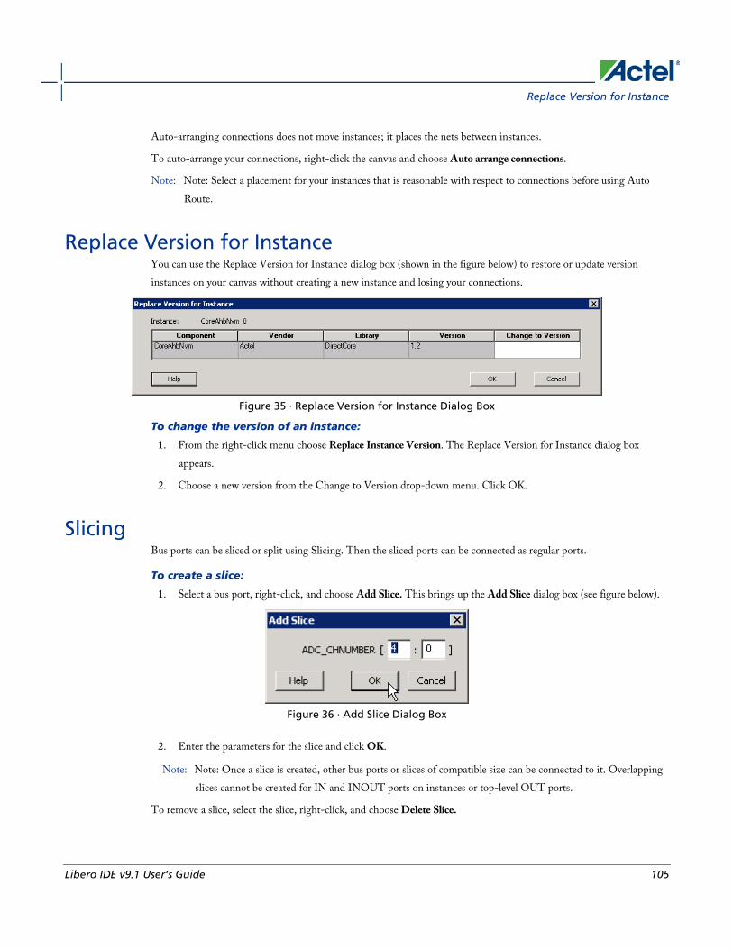
Replace Version for Instance
Libero IDE v9.1 User’s Guide 105
Auto-arranging connections does not move instances; it places the nets between instances.
To auto-arrange your connections, right-click the canvas and choose Auto arrange connections.
Note: Note: Select a placement for your instances that is reasonable with respect to connections before using Auto Route.
Replace Version for Instance You can use the Replace Version for Instance dialog box (shown in the figure below) to restore or update version instances on your canvas without creating a new instance and losing your connections.
Figure 35 · Replace Version for Instance Dialog Box
To change the version of an instance:
1. From the right-click menu choose Replace Instance Version. The Replace Version for Instance dialog box appears.
2. Choose a new version from the Change to Version drop-down menu. Click OK.
Slicing Bus ports can be sliced or split using Slicing. Then the sliced ports can be connected as regular ports.
To create a slice:
1. Select a bus port, right-click, and choose Add Slice. This brings up the Add Slice dialog box (see figure below).
Figure 36 · Add Slice Dialog Box
2. Enter the parameters for the slice and click OK.
Note: Note: Once a slice is created, other bus ports or slices of compatible size can be connected to it. Overlapping slices cannot be created for IN and INOUT ports on instances or top-level OUT ports.
To remove a slice, select the slice, right-click, and choose Delete Slice.

Canvas View
106 Libero IDE v9.1 User’s Guide
Instance Properties Right-click a component instance and choose Properties to view the Name, Instance Name, and port information -name/direction-.
This dialog box is useful if you want to view the list of Port Names available in the instance from the Canvas view instead of the Grid.
See Also Grid overview
Display panel
Connection panel
Rename Net To rename a net:
1. Right-click the net on the Canvas and choose Rename Net. This opens the Rename Net dialog box.
2. Type in a new name for the net.
Note: Note: The system automatically assigns net names to nets if they are not explicitly specified. Once you have specified a name for a net, that name will not be over-written by the system.
Automatic Names of Nets Nets are automatically assigned names by the tool according to the following rules:
In order of priority
1. If user named then name = user name
2. If net is connected to top-level port then name = port name; if connected to multiple ports then pick first port
3. If the net has no driver, then name = net_[i]
4. If the net has a driver, name = instanceName_driverpinName
Slices
For slices, name = instanceName_driverpinName_sliceRange; for example u0_out1_4to6.
GND and VCC Nets
The default name for GND/VCC nets is net_GND and net_VCC.
Expanded Nets for Bus Interface Connections
Expanded nets for bus interface connections are named busInterfaceNetName_<i>_driverPinName.

Organizing Your Design on the Canvas
Libero IDE v9.1 User’s Guide 107
Organizing Your Design on the Canvas You may find it easier to create and navigate your SmartDesign if you organize and label the instances and busses on the Canvas.
You can show and hide nets, lock instances, rotate busses, group and ungroup pins, rename instances / groups / pins, and auto-arrange instances.
To organize your design:
1. Click the Auto-Arrange button to automatically arrange instances on the Canvas. SmartDesign's auto-arrange feature optimizes instance location according to connections and instance size.
2. Right-click any instance and choose Lock Location to fix the placement. Auto-Arrange will not move any instances that are locked.
3. Click Auto-Arrange again to further organize any unlocked instances. Continue arranging and locking your instances until you are satisfied with the layout on the Canvas.
If your design becomes too cluttered:
1. Hide the display of nets by de-selecting Canvas > Nets. This hides all the scalar and bus nets on your Canvas. You can also right-click a pin and choose Show Net (or Hide Net) to show/hide individual nets. Note that selecting a pin will make the corresponding net temporarily visible.
2. Group your pins. It may help to group pins that are functionally similar, or to group pins that are already connected or will be unused in your design.
To further customize your design's appearance:
1. Double-click the names of instances to add custom names. For example, it may be useful to rename an instance based on a value you have set in the instance: the purpose of an instance named 'array_adder_bus_width_5' is easier to remember than 'array_adder_0'.
2. Right-click any bus and choose Shape > Rotate Left or Right to change the bus orientation (horizontal or vertical). Click and drag the bus to a new location and lock, if necessary.

Grid
108 Libero IDE v9.1 User’s Guide
Grid
Grid Overview The Grid (see image below) provides a mechanism for making manual connections between building blocks in your design. The grid displays your design in a spreadsheet for sorting and filtering, enabling you to quickly access and manipulate any subset of your design.
The Grid shows block instances vertically and horizontally on the spreadsheet, such that the port rows on the spreadsheet intersect with port columns. Each intersection of rows and ports on the spreadsheet provides a connection opportunity.
The grid is divided into two panels, the Display panel and the Connection panel.
The Grid offers two different views: the Instance-Instance view and the Net-Instance view. The behavior of the two panels is the same in both views.
The default display of the Grid shows connections between all the instances in your design in an Instance-Instance view.
Actel recommends that you work with only a subset of the instances in the current design when making manual connections. This greatly reduces the information displayed in the Grid view and makes it easier to create manual connections.
Click the Maximize Work Area button to hide the other windows and show more of the Grid.
To create new Grids with just a subset of instances, select the instances between which you are making connections on the Canvas, then right-click and choose Edit Connections. A new Grid will be displayed, with only those instances and the top-level. When you are done making connections, right-click the grid view name tab and close the subset view.
To further simplify the data search in the grid and to make connections efficiently, use Filtering, Hierarchical sort in the instance-instance view, and the find unconnected ports (Hide All Connected Ports) features.

Display Panel
Libero IDE v9.1 User’s Guide 109
Figure 37 · Grid (Instance-Instance View)
To switch to Net-Instance view, click the Net-Instance view radio button.
To reset to the default view, from the Grid menu, choose Reset Instance [Net] View to Default.
See Also Grid - Display panel icons
Grid - Connection panel icons
Display Panel You can use the fields in the Display panel to manage content. To add or remove a field, right-click the field title (such as Instance in the image below) and from the right-click menu choose Fields. New fields appear to the right of the fields already shown. To filter the list of nets or instances in the Display panel, use the Custom Filter.

Grid
110 Libero IDE v9.1 User’s Guide
Figure 38 · Instance-Instance View Display Panel
The Display panel may list the following fields:
• Instance: Displays instances in the current design.
• Direction: Displays the port direction and bus interface type. Port directions are defined as IN, OUT and INOUT, bus interfaces are shown as MASTER, SLAVE, and SYSTEM.
• Port Name: Lists port names for all instances. Also displays an icon that indicates if the port is connected (green), disconnected (white), partially connected (green and white), input (I), output (O), master (yellow M), INOUT (small horizontal arrows), a system bif, or slave (S).
• Slice: Displays bit order (i.e. [7:0]) of busses and slices. Slice is not available for scalars and bus interfaces.
• Width: Displays the size of the bus for any bus port. One for a scalar and zero for a bus interface port.
• Net: Identifies the net for each instance connection.
Click the plus button to expand the information listed for the selected instance or direction. Click the minus button to collapse the information displayed for the selected instance or direction. You can add and remove fields to meet
your needs.
Use the filter button to filter the contents of each column. To sort the content of a column, click the Filter button and select Sort Ascending or Sort Descending. Choose Custom Filter to open the Custom Filter dialog box. You can use the Custom Filter dialog box to choose the nets, instances and slices you wish to display.

Display Panel
Libero IDE v9.1 User’s Guide 111
Right-click the column heading and choose Fit This Column To Data to expand (or shrink) the column to match the column width to the size of the field name.
Promoting ports to top level To automatically promote a port to top level, select the port, right-click, and choose Promote To Top Level. This automatically creates top-level ports of that name and connects the selected ports to them. If a port name already exists, a choice is given to either connect to the existing ports or to create a new port with a name <port name>_<i> where i = 1…n.
Bus slices cannot be automatically promoted to top level. You must create a top level port of the bus slice width and then manually connect the bus slice to the newly created top level port.
Tying off input pins Click in the Grid Attribute column and select Invert, Tie Low, or Tie High to tie the Port.
Making driver and bus interface pins unused Driver or bus interface pins can be marked unused (floating/dangling) if you do not intend to use them as a driver in the design. If you mark a pin as unused the Design Rules Check does not return Floating Driver or Unconnected Bus Interface messages on the pin.
Once a pin is explicitly marked as unused it cannot be used to drive any inputs. The unused attribute must be explicitly removed from the pin in order to connect it later. To mark a driver or bus interface pin as unused:
• Right-click the driver or bus interface pin and choose Mark as Unused
• In the Grid Attribute column, click the attribute and select Mark as Unused
Finding unconnected and partially connected ports The grid allows you to quickly find all the unconnected ports in your design. To filter the grid to only show these ports, from the SmartDesign menu, choose Grid > Hide All Connected Ports.
Compatibility rules • If the port selected on the row is a top-level port with a direction IN or an instance port with direction OUT, all
ports of direction IN and INOUT on the instances are compatible with it.
• If the port selected on the row is a top-level port with direction OUT or instance port with direction IN or INOUT, all ports with direction IN are compatible with it.
• Bus ports or slices are only compatible with bus ports or slices of equal size.
• If there are no compatible connections between a port in the row area and an instance in the column area, the cell is shaded and unavailable.
• The pull-down menu in the cells only lists compatible ports.

Grid
112 Libero IDE v9.1 User’s Guide
See Also Connection panel
Making connections
Filtering views
Grid - Display panel icons
Connection Panel The Connection panel (the area to the right side of the grid) shows the Attribute column, the "top" (top-level), and the Port Name to which the port is connected (if any).
Figure 39 · Instance-Instance Connection Panel
Use the filter button to filter and select which columns you wish to view, or to sort the contents of the columns in ascending or descending order.
Attribute Column The attribute column specifies additional properties of a port on the instance. These are:
PAD - Indicates that the port is a chip-level package pin. In SmartDesign, these ports are automatically promoted to the top-level and are read only.
BIF - Indicates that the port is a Bus Interface.
GND - Tie the port to logic 0.
VCC - Tie the port to logic 1.

Connection Panel
Libero IDE v9.1 User’s Guide 113
Invert - Invert the polarity of this port. Inverting a port automatically instantiates an inverter into the generated HDL file:
• For a driver: Inverter added after pin or port.
• For a non-driver: Inverter added before pin or port.
Unused - Indicates the pin has been assigned the float attribute and is not included in the Design Rules Check.
<design name> Column The <design name> column represents the top-level; the name of the column depends on the name of your design.
Instances Column(s) An instance column represents an instance that an instance-port of a row can be connected to.
See Also Display panel
Making connections
Filtering views
Grid - Connection panel icons

Instance-Instance View
114 Libero IDE v9.1 User’s Guide
Instance-Instance View
Instance-Instance View The Instance-Instance view (see figure below) is divided into two panels: the Display panel and the Connection panel. By default, the Display panel shows Instance, Port Name, and Slice information.
By default, the Connection panel begins at the Attribute column, and lists instances in the design and their ports. You can show/hide any column in either panel; if you modify the view and wish to reset it, right-click the Instance-Instance View radio button in the Display panel and choose Reset Instance View to Default.
Figure 40 · Instance - Instance View
Adding and Removing Fields To add a field in the Display panel, right-click the field title (such as Direction in the image below) and from the right-click menu choose Field, and select the field you wish to add or remove. Added fields appear at the end of the list of fields.
You can add fields to view additional information about a port. Also, adding the field enables you to Sort your design based on fields.

Sorting with Fields
Libero IDE v9.1 User’s Guide 115
Figure 41 · Add Field Menu in Display Panel
To add an instance in the Connection panel, click the drop-down arrow in Instances (as shown in the figure below), and choose Custom Filter. The Custom Filter dialog box appears. Select checkbox for the instance you wish to view, or use the Find box to search for a specific instance or range of instances.
Figure 42 · Add an Instance with Custom Filter in Connection Panel
Sorting with Fields The field columns inside the Grid can be used to sort the ports in your design.
The hierarchical order is defined by the order of the columns (left to right). The data within each field is sorted alphabetically. To change the hierarchical view, select a column and drag the column to the left or the right.
For example, this may be useful if you wish to see all of your INPUT ports together or if you want to see all of your 8-bit busses together. The image below shows the Display Panel sorted by Port Name.
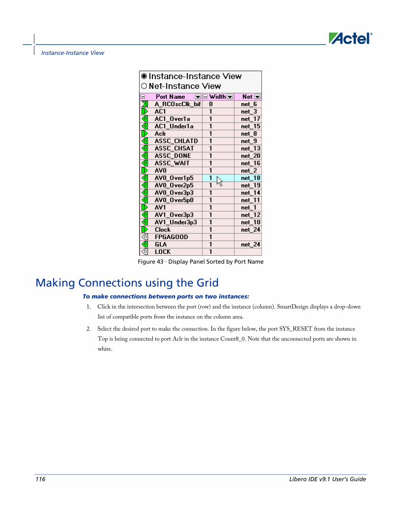
Instance-Instance View
116 Libero IDE v9.1 User’s Guide
Figure 43 · Display Panel Sorted by Port Name
Making Connections using the Grid To make connections between ports on two instances:
1. Click in the intersection between the port (row) and the instance (column). SmartDesign displays a drop-down list of compatible ports from the instance on the column area.
2. Select the desired port to make the connection. In the figure below, the port SYS_RESET from the instance Top is being connected to port Aclr in the instance Count8_0. Note that the unconnected ports are shown in white.

Connecting Multiple Pins (Connection Panel)
Libero IDE v9.1 User’s Guide 117
Figure 44 · Making Connections Between Two Ports on Two Instances
To disconnect an existing connection, click in the intersection between the port and the instance and choose Disconnect.
See Also Connecting multiple ports (Connection panel)
Filtering views
Connecting Multiple Pins (Connection Panel) The Connect Multiple dialog box enables you to make multiple connections to a pin or net.
In the Instance to Instance view you can easily connect multiple non-driver pins from a single instance to a driver pin. To do so:
1. Click a cell intersection of a driver pin and you will see a drop down with Connect Multiple. Choose Connect Multiple to open the dialog box below.

Instance-Instance View
118 Libero IDE v9.1 User’s Guide
Figure 45 · Connect Multiple Pins Dialog Box - Instance to Instance
2. The dialog box lists all the compatible non-driver pins that can be connected to the selected driver pin. Click the checkbox to connect these pins to the driver pin.
In the Net to Instance view you can easily connect multiple pins from a single instance to a net. To do so:
1. Click a cell intersection of an existing net and you will see a drop down with Connect Multiple. Choose Connect Multiple to open the dialog box below. The dialog box lists all the compatible non-driver pins that can be connected to this net.
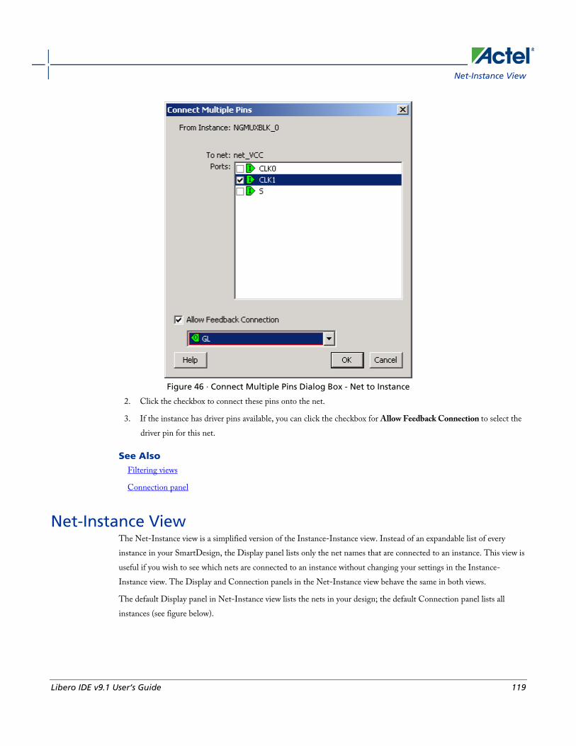
Net-Instance View
Libero IDE v9.1 User’s Guide 119
Figure 46 · Connect Multiple Pins Dialog Box - Net to Instance
2. Click the checkbox to connect these pins onto the net.
3. If the instance has driver pins available, you can click the checkbox for Allow Feedback Connection to select the driver pin for this net.
See Also Filtering views
Connection panel
Net-Instance View The Net-Instance view is a simplified version of the Instance-Instance view. Instead of an expandable list of every instance in your SmartDesign, the Display panel lists only the net names that are connected to an instance. This view is useful if you wish to see which nets are connected to an instance without changing your settings in the Instance-Instance view. The Display and Connection panels in the Net-Instance view behave the same in both views.
The default Display panel in Net-Instance view lists the nets in your design; the default Connection panel lists all instances (see figure below).

Instance-Instance View
120 Libero IDE v9.1 User’s Guide
Figure 47 · Net-Instance View, Display and Connection Panels
To switch to Net-Instance view, click the Net-Instance radio button. To reset to the default view, from the Grid menu, choose Reset Net View to Default.
See Also Connect to an existing net (Net-Instance view)
Connection panel
Display panel
Filtering views
Connect to an Existing Net (Net-Instance View) To connect to an existing net, select the ports to be connected from the drop-down list by clicking in the cell at the intersection of the net and the instance (see figure below).

Make New Connection (Net-Instance View)
Libero IDE v9.1 User’s Guide 121
Figure 48 · Connecting to an Existing Net
Any net can have at most one driver. IN ports of the top-level or OUT ports from instances are considered drivers. If another driver is for an already driven net, the current driver will be disconnected and the new driver will be connected to the selected net.
See Also Connection panel
Display panel
Make New Connection (Net-Instance View) To connect to a new net, select the ports to be connected from the drop-down list. Click the cell at the intersection of the (unconnected) net row and the instance. This creates a new net (see figure below).

Instance-Instance View
122 Libero IDE v9.1 User’s Guide
Figure 49 · Making a New Connection
See Also Connect to an existing net (Net-Instance view)
Connection panel
Display panel
Filtering Views To reduce the amount of data shown on the screen, you can display it selectively. The easiest way to hide an entry is to right-click the cell and choose Hide Selection. To show the entry again, you can right-click at the top and choose Show All Rows.
For more control over the data display, use the Custom Filter available from the button on the header row.
The Grid enables you to filter all instances within the design, as well as their direction, ports and slices. The example below filters by instance, but you can filter any column in the Display panel with the same procedure.
To filter the contents in the grid:
1. Use the filter button and choose Custom Filter to bring up the filter box (see figure below).

Filtering Views
Libero IDE v9.1 User’s Guide 123
Figure 50 · Custom Filter Box in the Display Panel
2. From the filter box, you can find and select multiple values. In the image above, the Find field has highlighted all the instances that start with 'my', * is a wildcard. You must click inside the checkbox to select, or de-select, highlighted values.
3. Click OK to commit your changes.
To hide data in the grid:
Select the rows you want to hide, right-click and choose Hide Selection.
To restore grid data:
From the SmartDesign menu, choose Connectivity View > Reset Instance View to Default.
See Also Connection panel
Display panel
Making connections

Schematic View
124 Libero IDE v9.1 User’s Guide
Schematic View
Schematic Overview The Schematic view (see figure below) displays a detailed connection diagram for all instances, ports, and pins in the current design with lines representing nets. This view is the closest representation to the exported HDL.
You can zoom the contents in the Schematic view or split the Schematic view into multiple pages.
Figure 51 · Schematic View
Page Splitting By default, the Schematic view displays large designs using multiple pages. Page splitting enables you to quickly compute and display the schematic. You can turn off page splitting to view your entire design on a single page. For larger designs, when this option is turned off, it may take SmartDesign longer to display the schematic.
To turn page splitting on or off, from the SmartDesign menu, choose Schematic View > Allow Page Splitting.
To navigate to the next page in a design, from the SmartDesign menu, choose Schematic View > Go to Next Page.
To navigate to the previous page, from the SmartDesign menu, choose Schematic View> Go to Previous Page.
To navigate to the first page, from the SmartDesign menu, choose Schematic View > Go to First Page.
To navigate to the last page, from the SmartDesign menu, choose Schematic View> Go to Last Page.

Zooming
Libero IDE v9.1 User’s Guide 125
Zooming The zoom tool in the Schematic View enables you to zoom fit the contents of your design within the window.
To zoom fit the design, click and drag to the bottom left corner of the window.
Zoom in and out of your schematic using the zoom icons on your toolbar.
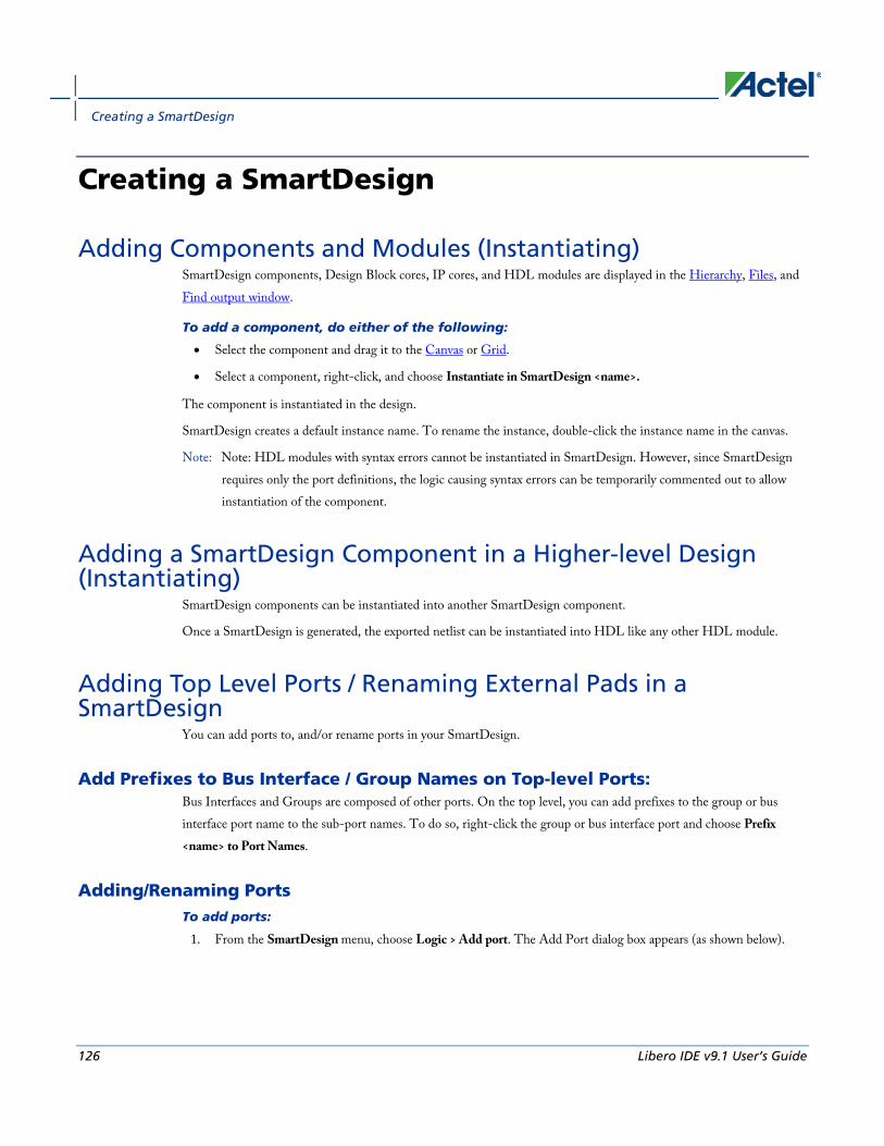
Creating a SmartDesign
126 Libero IDE v9.1 User’s Guide
Creating a SmartDesign
Adding Components and Modules (Instantiating) SmartDesign components, Design Block cores, IP cores, and HDL modules are displayed in the Hierarchy, Files, and Find output window.
To add a component, do either of the following:
• Select the component and drag it to the Canvas or Grid.
• Select a component, right-click, and choose Instantiate in SmartDesign <name>.
The component is instantiated in the design.
SmartDesign creates a default instance name. To rename the instance, double-click the instance name in the canvas.
Note: Note: HDL modules with syntax errors cannot be instantiated in SmartDesign. However, since SmartDesign requires only the port definitions, the logic causing syntax errors can be temporarily commented out to allow instantiation of the component.
Adding a SmartDesign Component in a Higher-level Design (Instantiating)
SmartDesign components can be instantiated into another SmartDesign component.
Once a SmartDesign is generated, the exported netlist can be instantiated into HDL like any other HDL module.
Adding Top Level Ports / Renaming External Pads in a SmartDesign
You can add ports to, and/or rename ports in your SmartDesign.
Add Prefixes to Bus Interface / Group Names on Top-level Ports: Bus Interfaces and Groups are composed of other ports. On the top level, you can add prefixes to the group or bus interface port name to the sub-port names. To do so, right-click the group or bus interface port and choose Prefix <name> to Port Names.
Adding/Renaming Ports To add ports:
1. From the SmartDesign menu, choose Logic > Add port. The Add Port dialog box appears (as shown below).
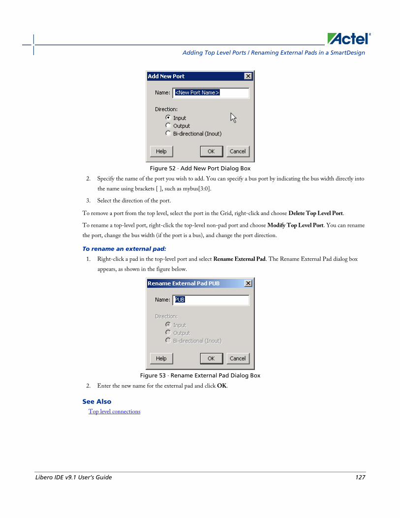
Adding Top Level Ports / Renaming External Pads in a SmartDesign
Libero IDE v9.1 User’s Guide 127
Figure 52 · Add New Port Dialog Box
2. Specify the name of the port you wish to add. You can specify a bus port by indicating the bus width directly into the name using brackets [ ], such as mybus[3:0].
3. Select the direction of the port.
To remove a port from the top level, select the port in the Grid, right-click and choose Delete Top Level Port.
To rename a top-level port, right-click the top-level non-pad port and choose Modify Top Level Port. You can rename the port, change the bus width (if the port is a bus), and change the port direction.
To rename an external pad:
1. Right-click a pad in the top-level port and select Rename External Pad. The Rename External Pad dialog box appears, as shown in the figure below.
Figure 53 · Rename External Pad Dialog Box
2. Enter the new name for the external pad and click OK.
See Also Top level connections

Connecting Instances
128 Libero IDE v9.1 User’s Guide
Connecting Instances
Automatic Connections Using automatic connections (as shown in the figure below) enables the software to connect your design efficiently, reducing time required for manual connections and the possibility of introducing errors.
To auto connect the bus interfaces in your design, right-click the design Canvas and select Auto Connect, click the
Auto Connect button ; or from the SmartDesign menu, choose Auto Connect.
You can select individual pins or groups on the Canvas to auto-connect. Select the pins, right-click and choose Auto Connect.
SmartDesign searches your design and connects all compatible bus interfaces.
SmartDesign will also form known connections for any SoC systems such as the processor CLK and RESET signals.
If there are multiple potential interfaces for a particular bus interface, Auto Connect will not attempt to make a connection; you must connect manually. You can use the Canvas, Grid or the Find Compatible Bus Interface dialog box to make the manual connection.
Figure 54 · Auto-Connected IP Cores
Manual Connections To make manual connections between to pins on the Canvas, select both pins (use CTRL + click), right-click either pin and choose Connect. If the pins cannot be legally connected the connection will fail.
Deleting Connections
Libero IDE v9.1 User’s Guide 129
Deleting Connections To delete a net connection on the Canvas, click to select the net and press the Delete key, or right-click and choose Delete.
To remove all connections from one or more instances on the Canvas, select the instances on the Canvas, right-click and choose Clear all Connections. This disconnects all connections that can be disconnected legally.
You can also select one or more rows in the Grid and choose Remove Connections from Selected Ports from the right-click menu to remove the connects for a group of Ports.
If you click in a cell displaying a connection, selecting Disconnect from the drop down removes just that connection.
Certain connections to ports with PAD properties cannot be disconnected. PAD ports must be connected to a design’s top level port. PAD ports will eventually be assigned to a package pin. In SmartDesign, these ports are automatically promoted to the top level and cannot be modified or disconnected.
Top-level Connections Connections between instances of your design normally require an OUTPUT (Driver Pin) on one instance to one or more INPUT(s) on other instances. This is the basic connection rule that is applied when connecting.
However, directions of ports at the top level are specified from an external viewpoint of that module. For example, an INPUT on the top level is actually sending (‘driving’) signals to instances of components in your design. An OUTPUT on the top level is receiving (‘sinking’) data from a Driver Pin on an internal component instance in your SmartDesign design.
The implied direction is essentially reversed at the top-level. Making connections from an OUTPUT of a component instance to an OUTPUT of top-level is legal.
This same concept applies for bus interfaces; with normal instance to instance connections, a MASTER drives a SLAVE interface. However, they go through a similar reversal on the top-level.
Bus Interfaces
130 Libero IDE v9.1 User’s Guide
Bus Interfaces
About Bus Interfaces A bus interface is a standard mechanism for specifying the interconnect rules between components or instances in a design. A bus definition consists of the roles, signals, and rules that define that bus type. A bus interface is the instantiation of that bus definition onto a component or instance.
The available roles of a bus definition are master, slave, and system.
A master is the bus interface that initiates a transaction (such as read or write) on a bus.
A slave is the bus interface that terminates/consumes a transaction initiated by a master interface.
A system is the bus interface that does not have a simple input/output relationship on both master/slave. This could include signals that only drive the master interface, or only drive the slave interface, or drive both the master and slave interfaces. A bus definition can have zero or more system roles. Each system role is further defined by a group name. For example, you may have a system role for your arbitration logic, and another for your clock and reset signals.
Mirror roles are for bus interfaces that are on a bus core, such as CoreAHB or CoreAPB. They are equivalent in signal definition to their respective non-mirror version except that the signal directions are reversed.
The diagram below is a conceptual view of a bus definition.

Using Bus Interfaces in SmartDesign
Libero IDE v9.1 User’s Guide 131
Figure 55 · Bus Definition
See Also: Using bus interfaces in SmartDesign
Using Bus Interfaces in SmartDesign Adding bus interfaces to your design enables SmartDesign to do the following:
• Auto connect compatible interfaces
• Enforce DRC rules between instances in your design

Bus Interfaces
132 Libero IDE v9.1 User’s Guide
• Search for compatible components in the project
The Catalog in the Project Manager contains a list of Actel-specific and industry standard bus definitions, such as AMBA.
You can add bus interfaces to your design by dragging the bus definitions from the Bus Definitions tab in the Catalog onto your instances inside SmartDesign.
Some Actel cores have bus interfaces that are instantiated during generation.
Certain bus definitions cannot be instantiated by a user. Typically these are the bus definitions that define a hardwired connection and are specifically tied to a core/macro. They are still available in the catalog for you to view their properties, but you will not be able to add them onto your own instances or components. These bus definitions are grayed out in the Catalog.
A hardwired connection is a required silicon interconnect that must be present and specifically tied to a core/macro. For example, when using the Real Time Counter in a Fusion design you must also connect it to a Crystal Oscillator core.
Maximum masters allowed - Indicates how many masters are allowed on the bus.
Maximum slaves allowed - Indicates how many slaves are allowed on the bus.
Default value - indicates the value that the input signal will be tied to if unused. See Default tie-offs with bus interfaces.
Required connection - Indicates if this bus interface must be connected for a legal design.
Hover your mouse over a bus definition in the Project Manager Bus Definition Catalog to view the masters/slave/default/required connection information.
Adding Bus Interfaces to SmartDesign Components To add a bus interface to a component:
1. Select a bus definition from the Bus Definitions tab in the Catalog and drag it onto your top-level. The Add Bus Interface dialog box opens (see figure below). A default name is assigned to your bus interface; you can specify your own if you wish.
Adding Bus Interfaces to SmartDesign Instances
Libero IDE v9.1 User’s Guide 133
Figure 56 · Add Bus Interface Dialog Box
2. Click Map by Name to map the signals automatically. Map By Name attempts to map any similar signal names between the bus definition and pin names on the instance.
3. (Optional) Click the Add Port checkbox to add ports to the top-level. If you choose to add ports, the Signal row becomes a text editable field.
Adding Bus Interfaces to SmartDesign Instances To add a bus interface to your instance:
1. Select a bus definition from the Bus Definition tab in the Catalog and drag it onto your instance. The Add Bus Interface dialog box opens (see figure below). A default name is assigned to your bus interface; you can specify your own if you wish.
Bus Interfaces
134 Libero IDE v9.1 User’s Guide
Figure 57 · Add Bus Interface Dialog Box
2. If necessary, enter the configuration parameters.
3. Click Map by Name to map the signals automatically. Map By Name attempts to map any similar signal names between the bus definition and pin names on the instance.
Removing Bus Interfaces from Instances Only bus interfaces that you explicitly added to an instance can be removed or deleted. Bus interfaces that were instantiated as part of core generation cannot be deleted.
To delete user added bus interfaces, on the Canvas , select the bus interface pin object, right-click, and choose Delete Bus Interface; or, in the Grid, select the Port Name field, right-click, and choose Delete Bus Interface.
Viewing Bus Interface Properties To view the properties of a bus interface:
In the Canvas, select the bus interface pin object, right-click, and choose Properties. This opens the View Bus Interface dialog box (see figure below).

Viewing Bus Interface Properties
Libero IDE v9.1 User’s Guide 135
Figure 58 · View Bus Interface Properties Dialog Box
Bus Interface Details Bus Interface Name: Name of bus interface.
Instance Name: Specifies the name of the instance.
Bus Definition: Specifies the name of the bus interface.
Role: Specifies the bus role (master or slave).
Vendor: Specifies the vendor for the bus interface.
Version: Specifies the version for the bus interface.
Configuration Parameters Certain bus definitions contain user configurable parameters.

Bus Interfaces
136 Libero IDE v9.1 User’s Guide
Parameter: Specifies the parameter name.
Value: Specifies the value you define for the parameter.
Consistent: Specifies whether a compatible bus interface must have the same value for this bus parameter. If the bus interface has a different value for any parameters that are marked with consistent set to yes, this bus interface will not be connectable.
Signal Map Definition The signal map of the bus interface specifies the pins on the instance that correspond to the bus definition signals. The bus definition signals are shown on the left, under the Bus Interface Definition. This information includes the name, direction, width, and required properties of the signal.
The pins for your instance are shown in the columns under the Component Instance. The signal element is a drop-down list of the pins that can be mapped for that definition signal. Only pins that have the same direction and width requirements will be shown.
If the Req field of the signal definition is Yes, you must map it to a pin on your instance for this bus interface to be considered legal. If it is No, you can leave it unmapped.
If the Width field is Any there is no restriction on the width for this definition signal. That means a pin of any width on your instance can be mapped to this signal. During bus interface connection, if the instance pins are of differing widths, the bit connections will start from right to left. For example, if a 16-bit bus is connected to an 8-bit bus, the 8-bit bus will be connected to bits 7 down to 0 of the 16-bit bus. The higher bits will be unmapped and tied off at generation time.
Modifying Bus Interface Details Only bus interfaces that you explicitly added to an instance can be modified. Bus interfaces that were instantiated as part of core generation cannot be modified.
To modify the properties of a bus interface:
1. In the Canvas, select the bus interface pin object, right-click, and choose Modify Bus Interface (see figure below).
Finding Compatible Bus Interfaces
Libero IDE v9.1 User’s Guide 137
Figure 59 · Modify Bus Interface Dialog Box
2. Modify the bus interface details, configuration parameters, or signal map definition and click OK.
Map By Name attempts to map any similar signal names between the bus definition and pin names on the instance.
Finding Compatible Bus Interfaces The SmartGuide feature helps you complete your design; when you have a specific bus interface on an instance, you can find a compatible instance, component, or core to connect.
To find a compatible bus interface:
1. In the Canvas, select the bus interface pin object, right-click, and choose Find Compatible Bus Interface. This brings up the Find Compatible Bus Interface dialog box, showing the compatible instances, components, or cores that have the bus interface. SmartGuide searches all the instances in the current SmartDesign for any compatible bus interfaces. SmartGuide also searches through all the configured components in the Libero IDE project for any compatible bus interfaces, then searches through the Cores Catalog for any cores that may potentially contain a compatible bus interface when generated.

Bus Interfaces
138 Libero IDE v9.1 User’s Guide
Figure 60 · Find Compatible Bus Interface Dialog Box
2. Select a compatible instance, component or core and click OK.
• Selecting an instance from this list automatically connects that instance to the selected bus interface.
• Selecting a component from this list automatically instantiates that component into the design and connects it to the selected bus interface.
• Selecting a core from this list automatically brings up the configurator for that core and enables you to generate a new core. It will then be added to the design and connected. Note that it is possible to configure a core such that no compatible bus interface is generated; you will be given the opportunity to reconfigure the core in this scenario.
Actel Bus Interfaces The Catalog provides the following Actel-specific bus interfaces:
ExtSeqCtrl This bus interface defines the set of signals required to interface to the Analog System External Sequence Control. If the Analog System is configured with more than a single procedure, it will export this bus interface. Your own logic would need to connect to this bus interface to properly communicate and control the sequencer.

Actel Bus Interfaces
Libero IDE v9.1 User’s Guide 139
RTCXTL This bus interface represents the hardwired connection needed between the Real Time Counter and the Crystal Oscillator.
RTCVR This bus interface represents the hardwired connection needed between the Real Time Counter and the Voltage Regulator Power Supply Monitor.
InitCfg This is the initialization and configuration interface that is generated as part of the Flash Memory Builder. Any clients can be initialized from the Flash Memory as long as it can connect to this bus interface. This is for pure initialization clients that do not require save-back to the Flash Memory.
InitCfgSave This is the initialization and configuration interface that is generated as part of the Flash Memory Builder. Any client can be initialized or saved-back to the Flash Memory as long as it can connect to this bus interface. This is for clients that require initialization and save-back capabilities to the Flash Memory.
InitCfgCtrl This interface is used to initiate the save-back procedure of the Flash Memory.
InitCfgAnalog This interface is required between the Flash Memory System and the Analog System core.
FlashDirect This bus interface defines the set of signals that are required to interface directly to the Flash Memory. From the Flash Memory, if you add a data storage client, this interface will be exported. Interfacing to this interface enables direct access to the Flash Memory.
XTLOscClk This interface represents the Crystal Oscillator clock.
RCOscClk This interface represents the RC Oscillator clock.

Bus Interfaces
140 Libero IDE v9.1 User’s Guide
DirectCore Bus Interfaces The Catalog provides the following DirectCore bus interfaces.
AHB The AMBA AHB defines the set of signals for a component to connect to an AMBA AHB or AHBLite bus. The bus interface that is defined in the system is a superset of the signals in the AHB and AHBLite protocol. You can use the AHB bus interface in the bus definition catalog to connect your module to an AHB or AHBLite bus.
APB The AMBA APB defines the set of signals for a component to connect to an AMBA APB or APB3 bus. The bus interface that is defined in the system is a superset of the signals in the APB and APB3 protocol. You can use the APB bus interface in the bus definition catalog to connect your module to an APB or APB3 bus.
SysInterface The SysInterface is the interface used between the CoreMP7 and CoreMP7Bridge cores.
DBGInterface This is the set of debug ports on the CoreMP7 core.
CPInterface This is the co-processor interface on the CoreMP7 core.
Exposing Bus Interface Pins Pins that are contained as part of a bus interface will automatically be filtered out of the display. These ports are considered to be connected and used as part of a bus interface.
However, there are situations where you may wish to use the ports that are part of the bus interface as an individual port, in this situation you can choose to expose the pin from the bus interface.
To expose pins in a Bus Interface:
1. Select a bus interface port, right-click, and choose Expose Bus Interface Pins. The Expose Bus Interface Pin dialog box appears (as shown below).

Default Tie-offs with Bus Interfaces
Libero IDE v9.1 User’s Guide 141
Figure 61 · Expose Driver Pin Dialog Box
2. Click the checkbox associated with the driver pin you want to expose. Once the port is exposed it appears in the Grid and is available for individual connection.
Note: Note: If you have already connected the bus interface pin, then you will not be able to expose the non-driver pins. They will be shown grayed out in the dialog. This is to prevent the pin from being driven by two different sources.
To un-expose a driver pin, right-click the exposed port and choose Hide Bus Interface Pin.
Default Tie-offs with Bus Interfaces Bus definitions can contain default values for each of the defined signals. These default values specify what the signal should be tied to if it is mapped to an unconnected input pin on the instance.
Bus definitions are specified as required connection vs optional connection that defines the behavior of tie-offs during SmartDesign generation.
Required bus interfaces - The signals that are not required to be mapped will be tied off if they are mapped to an unconnected input pin.
Optional bus interfaces - All signals will be tied off if they are mapped to an unconnected input pin.
Tying Off (Disabling) Unused Bus Interfaces Tying off (disabling) a bus interface sets all the input signals of the bus interface to the default value.
To tie off a bus interface, right-click the bus interface and select Tie Off.
This is useful if your core includes a bus interface you plan to use at a later time. You can tie off the bus interface and it will be disabled in your design until you manually set one of the inputs.
Bus Interfaces
142 Libero IDE v9.1 User’s Guide
Some bus interfaces are required; you cannot tie off a bus interface that is required. For example, the Crystal Oscillator to RTC (RTCXTL) bus interface is a silicon interface and must be connected.
To enable your pin, right-click the pin and choose Clear Attribute.
Required vs. Optional Bus Interfaces A required bus interface means that it must be connected for the design to be considered legal. These are typically used to designate the silicon interconnects that must be present between certain cores. For example, when using the Real Time Counter in a Fusion design you must also connect it up to a Crystal Oscillator core.
An optional bus interface means that your design is still considered legal if it is left unconnected. However, it may not functionally behave correctly.
Figure 62 · Required Unconnected, Optional Unconnected, and Connected Bus Interfaces
See Also Canvas icons
Promoting Bus Interfaces to Top-level To automatically connect a bus interface to a top-level port, select the bus interface, right-click, and choose Promote To Top Level.
This automatically creates a top-level bus interface port of that name and connects the selected port to it. If a bus interface port name already exists, a choice is given to either connect to the existing bus interface port or to create a new bus interface port with a name <port name>_<i> where i = 1...n.
The signals that comprise the bus interface are also promoted.
Promoting a bus interface is a shortcut for creating a top-level port and connecting it to an instance pin.

Reconfiguring a Component
Libero IDE v9.1 User’s Guide 143
Incremental Design
Reconfiguring a Component To reconfigure a component used in a SmartDesign:
• In the Canvas, select the instance and double-click the instance to bring up the appropriate configurator, or the HDL editor; or select the instance, right-click it, and choose Configure Component.
• Select the component in the Hierarchy tab, Files tab or Find output window, and from the right-click menu select Open Component.
When the configurator is launched from the canvas, you cannot change the name of the component.
See Also Design state management
Replacing components
Fixing an Out-of-date Instance
Any changes made to the component will be reflected in the instance with an exclamation mark when you update the definition for the instance. An instance may be out-of-date with respect to its component for the following reasons:
• If the component interface (ports) is different – after reconfiguration - from that of the instance
• If the component has been removed from the project
• If the component has been moved to a different VHDL library
• If the SmartDesign has just been imported
You can fix an out-of-date instance by:
• Replacing the component with a new component (as shown in the figure below)
• Updating with the latest component
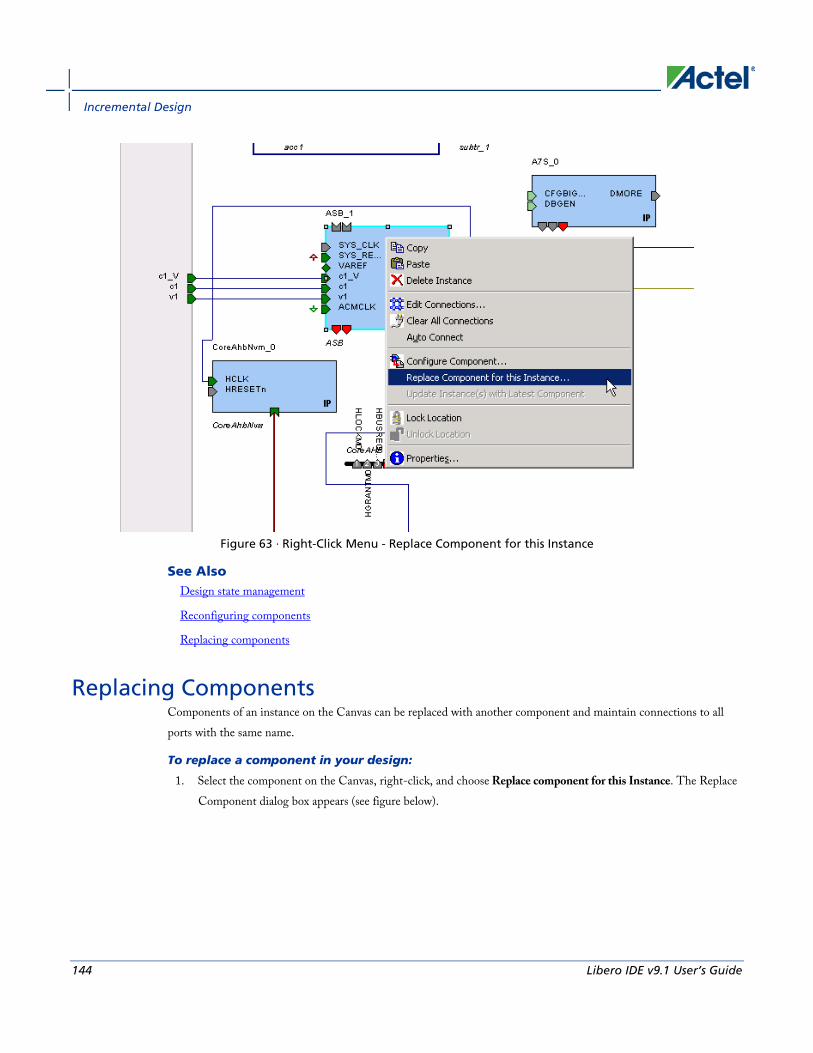
Incremental Design
144 Libero IDE v9.1 User’s Guide
Figure 63 · Right-Click Menu - Replace Component for this Instance
See Also Design state management
Reconfiguring components
Replacing components
Replacing Components Components of an instance on the Canvas can be replaced with another component and maintain connections to all ports with the same name.
To replace a component in your design:
1. Select the component on the Canvas, right-click, and choose Replace component for this Instance. The Replace Component dialog box appears (see figure below).

Design State Management
Libero IDE v9.1 User’s Guide 145
Figure 64 · Replace Component Dialog Box
2. Select the component you want to replace it with and click OK.
Design State Management When any component with instances in a SmartDesign design is changed, all instances of that component detect the change.
If the change only affects the memory content, then your changes do not affect the component's behavior or port interface and your SmartDesign design does not need to be updated.
If the change affects the behavior of the instantiated component, but the change does not affect the component's port interface, then your design must be resynthesized, but the SmartDesign design does not need to be updated.
If the port interface of the instantiated component is changed, then you must reconcile the new definition for all instances of the component and resolve any mismatches. If a port is deleted, SmartDesign will remove that port and clear all the connections to that port when you reconcile all instances. If a new port is added to the component, instances of that component will contain the new port when you reconcile all instances.
The affected instances are identified in your SmartDesign design in the Grid and the Canvas with an exclamation point. Right-click the instance and choose Update With Latest Component.
Note: Note: For HDL modules that are instantiated into a SmartDesign design, if the modification causes syntax errors, SmartDesign does not detect the port changes. The changes will be recognized when the syntax errors are resolved.
Changing memory content For certain cores such as Analog System Builder, Flash Memory, or FlexRAM it is possible to change the configuration such that only the memory content used for programming is altered. In this case Project Manager (IDE) will only invalidate your programming file, but your synthesis, compile, and place-and-route results will remain valid.
Incremental Design
146 Libero IDE v9.1 User’s Guide
When you modify the memory content of a core such as Analog System Builder or RAM with Initialization that is used by a Flash Memory core, the Flash Memory core indicates that one of its dependent components has changed and
that it needs to be regenerated. This indication will be shown in the Hierarchy or Files Tab .
In these cases, the Project Manager indicates that your programming file is out of date but your synthesis and place-and-route remain valid. You only need to regenerate your programming file in FlashPoint.
If any core is regenerated where the HDL file is not modified, the Project Manager design state will not invalidate your Synthesis and/or Place-and-Route results. Some specific cores are listed below.
RAM with Initialization core - You can modify the memory content without invalidating synthesis.
Analog System Builder core - You can modify the following without invalidating synthesis:
• Existing flag settings: threshold levels, assertion/de-assertion counts, OVER/UNDER type
• Modifying sequence order or adding sequence operations
• Changing acquisition times
• Resistor Value for the Current Monitor
• RTC time settings
• Gate Driver source current
Flash Memory System Builder core - You can modify the following without invalidating synthesis:
• Modifying memory file or memory content for clients
• JTAG protection for Init Clients
Design Rules Check To run the Design Rules Check, from the SmartDesign menu, choose Check Design Rules.
SmartDesign displays your design rule violations in the Design Rules Check grid (similar to the Grid), but with additional fields available: Type, Message and Details.
• Type displays an icon to indicate if the message is an error or a warning (as shown in the figure below). Error
messages are shown with a small red stop sign and warning messages with a yellow exclamation point.
• Message identifies the specific error/warning (see list below)
• Details provides information related to the Message

Design Rules Check
Libero IDE v9.1 User’s Guide 147
Figure 65 · Design Rules Check Results Grid
Unused Instance - You must remove this instance or connect at least one output pin to the rest of the design.
Out-of-date Instance - You must update the instance to reflect a change in the component referenced by this instance; see Fixing an out-of-date instance.
Undriven Pin - To correct the error you must connect the pin to a driver or change the state, i.e. tie low (GND) or tie high (VCC).
Floating Driver - You can mark the pin unused if it is not going to be used in the current design. Pins marked unused are ignored by the Design Rules Check.
Unconnected Bus Interface - You must connect this bus interface to a compatible port because it is required connection.
Required Bus Interface Connection – You must connect this bus interface before you can generate the design. These are typically silicon connection rules.
Exceeded Allowable Instances for Core – Some IP cores can only be instantiated a certain number of times for legal design. For example, there can only be one CortexM1 or CoreMP7 in a design because of silicon rules. You must remove the extra instances.
Incompatible Family Configuration – The instance is not configured to work with this project’s Family setting. Either it is not supported by this family or you need to re-instantiate the core.
Incompatible Die Configuration – The instance is not configured to work with this project’s Die setting. Either it is not supported or you need to reconfigure the Die configuration.
Incompatible ‘Debug’ Configuration – You must ensure your CoreMP7 and CoreMP7Bridge have the same ‘Debug’ configuration. Reconfigure your instances so they are the same.
No RTL License, No Obfuscated License, No Evaluation License – You do not have the proper license to generate this core. Contact Actel to obtain the necessary license.
No Top level Ports - There are no ports on the top level. To auto-connect top-level ports, right-click the Canvas and choose Auto-connect
Incremental Design
148 Libero IDE v9.1 User’s Guide
Generating a SmartDesign Component Before your SmartDesign component can be used by downstream processes, such as synthesis and simulation, you must generate it.
To generate a SmartDesign component, from the SmartDesign menu, choose Generate or click .
This will generate a HDL file in the directory <libero_project>/components/<library>/<yourdesign>.
Note: Note: The generated HDL file will be deleted when your SmartDesign design is modified and saved to ensure synchronization between your SmartDesign component and its generated HDL file.
Generating a SmartDesign component may fail if there are any DRC errors. DRC errors must be corrected before you generate your SmartDesign design.
Synthesizing the SmartDesign Component Synthesizing a SmartDesign component using the Project Manager is the same as any other design component. See the Synthesis help for more information on using the Project Manager to synthesize your design.
A SmartDesign component must be generated before it can be synthesized.
Note: Note: Once a component is set as root in the Project Manger Hierarchy, it can be synthesized.
Simulating the SmartDesign Component Simulating a SmartDesign component is identical to simulating any other element in the Libero IDE Project Manager Hierarchy (in the project using ModelSIM AE). See the ModelSIM AE with Libero IDE help and the ModelSIM help for more information.
Simulating IPs Some IPs are packaged with their own testbenches and verification suites. You can run these tests if you want to ensure the IP is working properly.
To simulate an individual DirectCore IP:
1. Generate your design.
2. In the Hierarchy, change the Show drop-down menu to Modules. This switches all the components to their module representation.
3. Select the IP that you wish to simulate, right-click and choose Set As Root. You may have to expand the Hierarchy to view the IP module you wish to simulate.
4. Click the Simulation icon in the Project Flow window to run simulation.

SmartDesign Menu
Libero IDE v9.1 User’s Guide 149
Reference
SmartDesign Menu
Command Icon Function
Show Canvas View
Displays the Canvas
Show Grid View
Displays the Grid
Show Schematic View
Displays the Schematic Viewer
Show Memory Map / Data Sheet
Displays the datasheet for the design
Check Design Rules
Runs the Design Rules Check
Generate Design
Generates your SmartDesign component
Auto Connect
Auto-connects instances
Add Port Adds a port to the top of the SmartDesign component
Canvas Menu
Command Icon Function
Auto-Arrange Instances
Auto-arranges the Canvas location of the instances on your Canvas; note that the Canvas location of the instances is a representation and not the actual layout.
Auto-Arrange Connections
Auto-arranges the Canvas location of the connections on your Canvas; note that the Canvas location of the instances is a representation and not the actual layout
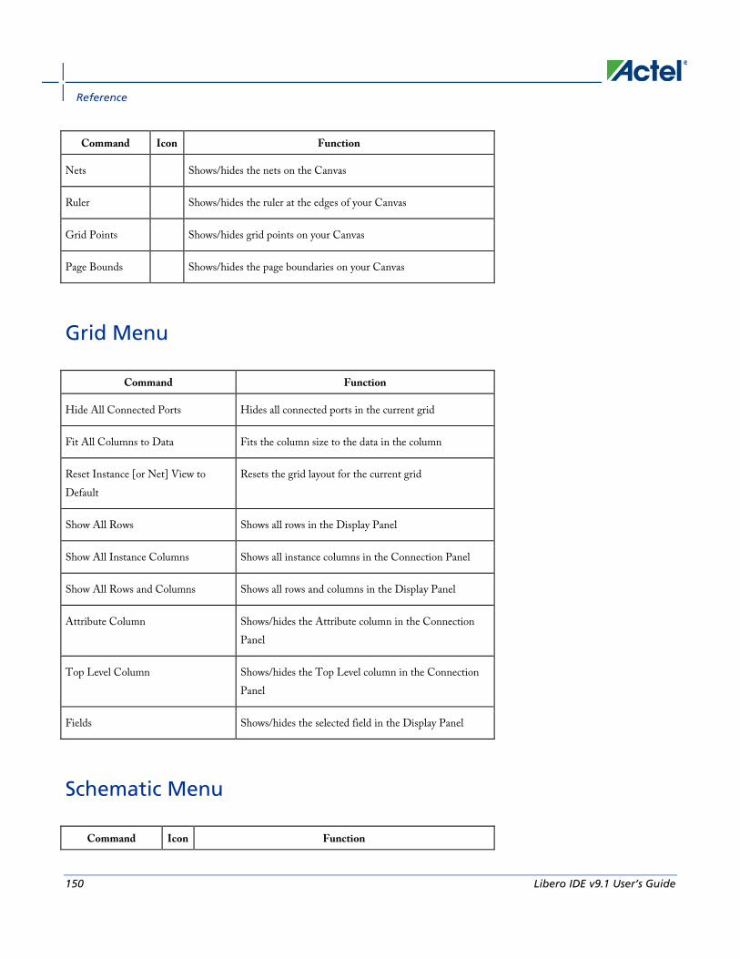
Reference
150 Libero IDE v9.1 User’s Guide
Command Icon Function
Nets Shows/hides the nets on the Canvas
Ruler Shows/hides the ruler at the edges of your Canvas
Grid Points Shows/hides grid points on your Canvas
Page Bounds Shows/hides the page boundaries on your Canvas
Grid Menu
Command Function
Hide All Connected Ports Hides all connected ports in the current grid
Fit All Columns to Data Fits the column size to the data in the column
Reset Instance [or Net] View to Default
Resets the grid layout for the current grid
Show All Rows Shows all rows in the Display Panel
Show All Instance Columns Shows all instance columns in the Connection Panel
Show All Rows and Columns Shows all rows and columns in the Display Panel
Attribute Column Shows/hides the Attribute column in the Connection Panel
Top Level Column Shows/hides the Top Level column in the Connection Panel
Fields Shows/hides the selected field in the Display Panel
Schematic Menu
Command Icon Function
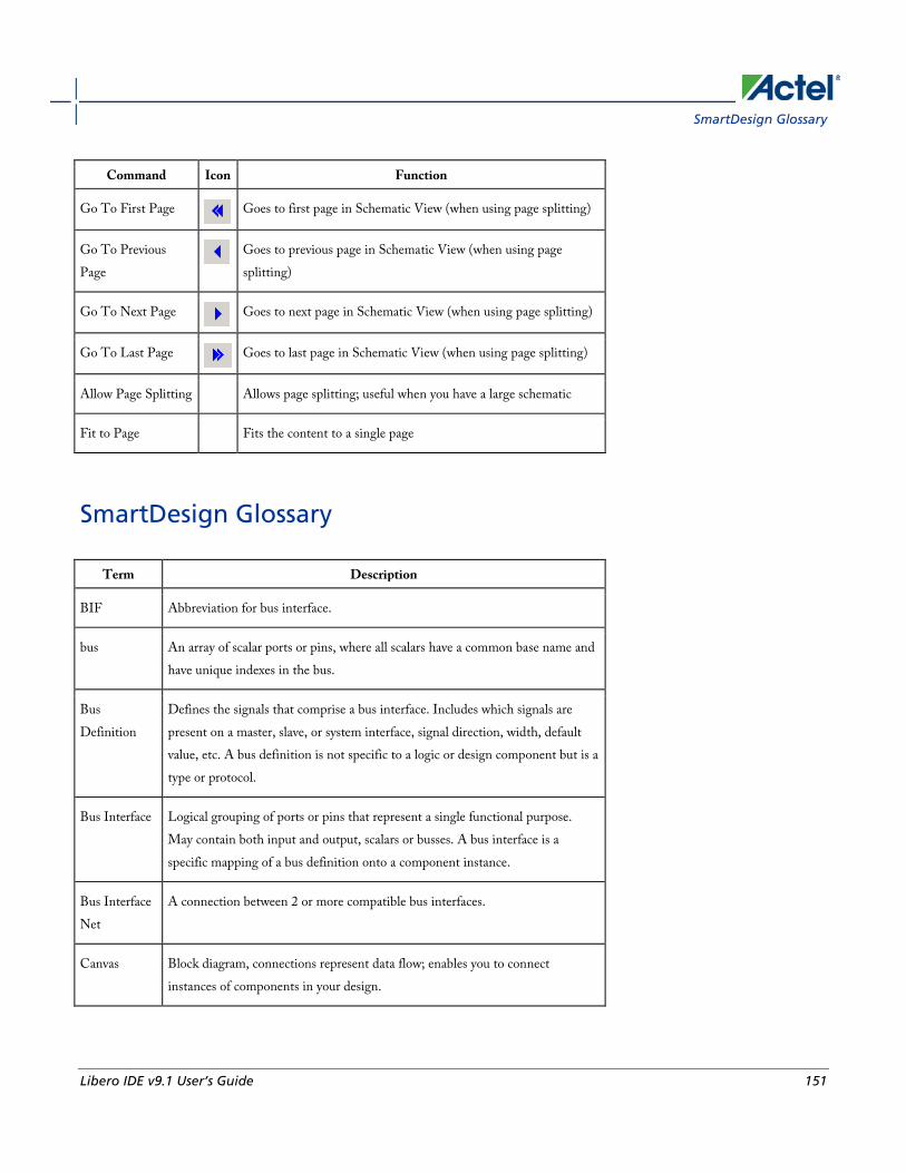
SmartDesign Glossary
Libero IDE v9.1 User’s Guide 151
Command Icon Function
Go To First Page
Goes to first page in Schematic View (when using page splitting)
Go To Previous Page
Goes to previous page in Schematic View (when using page splitting)
Go To Next Page
Goes to next page in Schematic View (when using page splitting)
Go To Last Page
Goes to last page in Schematic View (when using page splitting)
Allow Page Splitting Allows page splitting; useful when you have a large schematic
Fit to Page Fits the content to a single page
SmartDesign Glossary
Term Description
BIF Abbreviation for bus interface.
bus An array of scalar ports or pins, where all scalars have a common base name and have unique indexes in the bus.
Bus Definition
Defines the signals that comprise a bus interface. Includes which signals are present on a master, slave, or system interface, signal direction, width, default value, etc. A bus definition is not specific to a logic or design component but is a type or protocol.
Bus Interface Logical grouping of ports or pins that represent a single functional purpose. May contain both input and output, scalars or busses. A bus interface is a specific mapping of a bus definition onto a component instance.
Bus Interface Net
A connection between 2 or more compatible bus interfaces.
Canvas Block diagram, connections represent data flow; enables you to connect instances of components in your design.
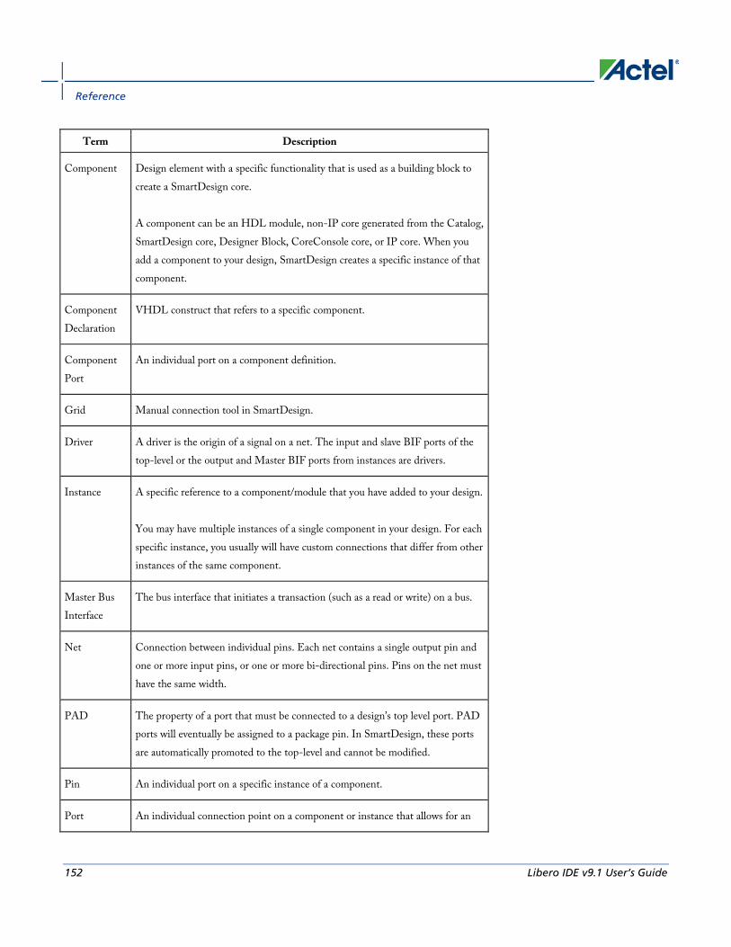
Reference
152 Libero IDE v9.1 User’s Guide
Term Description
Component Design element with a specific functionality that is used as a building block to create a SmartDesign core. A component can be an HDL module, non-IP core generated from the Catalog, SmartDesign core, Designer Block, CoreConsole core, or IP core. When you add a component to your design, SmartDesign creates a specific instance of that component.
Component Declaration
VHDL construct that refers to a specific component.
Component Port
An individual port on a component definition.
Grid Manual connection tool in SmartDesign.
Driver A driver is the origin of a signal on a net. The input and slave BIF ports of the top-level or the output and Master BIF ports from instances are drivers.
Instance A specific reference to a component/module that you have added to your design. You may have multiple instances of a single component in your design. For each specific instance, you usually will have custom connections that differ from other instances of the same component.
Master Bus Interface
The bus interface that initiates a transaction (such as a read or write) on a bus.
Net Connection between individual pins. Each net contains a single output pin and one or more input pins, or one or more bi-directional pins. Pins on the net must have the same width.
PAD The property of a port that must be connected to a design’s top level port. PAD ports will eventually be assigned to a package pin. In SmartDesign, these ports are automatically promoted to the top-level and cannot be modified.
Pin An individual port on a specific instance of a component.
Port An individual connection point on a component or instance that allows for an

Canvas Icons
Libero IDE v9.1 User’s Guide 153
Term Description
electrical signal to be received or sent. A port has a direction (input, output, bi-directional) and may be referred to as a ‘scalar port’ to indicate that only a single unit-level signal is involved. In contrast, a bus interface on an instance may be considered as a non-scalar, composite port. A component port is defined on a component and an instance port (also known as a ‘pin’) is part of a component instance.
Signal A net or the electrical message carried on a net.
Slave Bus Interface
Bus interface that terminates a transaction initiated by a master interface.
System Bus Interface
Interface that is neither master nor slave; enables specialized connections to a bus.
Top Level Port
An external interface connection to a component/module. Scalar if a 1-bit port, bus if a multiple-bit port.
Canvas Icons Canvas icons are listed below.
Hover your pointer over any icon in the SmartDesign Canvas view to display details.
Icon Description
Representation of an instance in your design. An instance is a component that has been added to your SmartDesign component. The name of the instance appears at the top and the name of the generic component at the bottom. The instance type is indicated by an icon inside the instance. There are specific icons for instances from SmartDesign, CoreConsole, HDL, and ViewDraw. The instance icon at left indicates an Actel core.
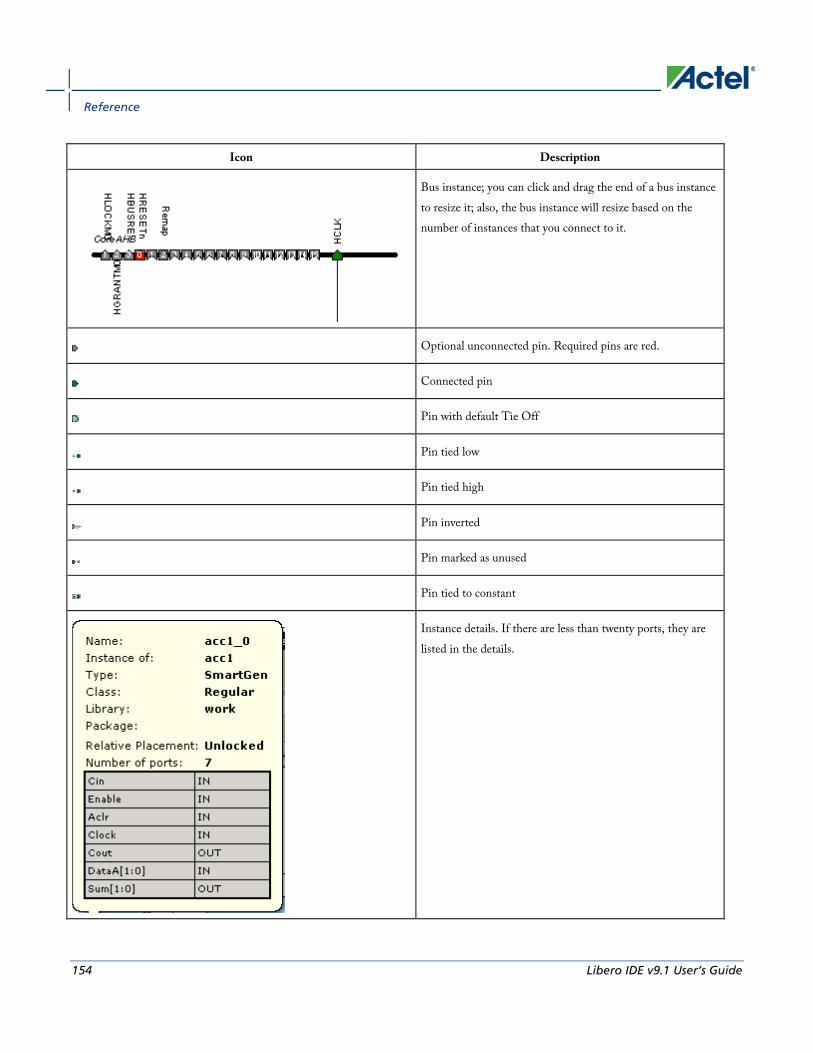
Reference
154 Libero IDE v9.1 User’s Guide
Icon Description
Bus instance; you can click and drag the end of a bus instance to resize it; also, the bus instance will resize based on the number of instances that you connect to it.
Optional unconnected pin. Required pins are red.
Connected pin
Pin with default Tie Off
Pin tied low
Pin tied high
Pin inverted
Pin marked as unused
Pin tied to constant
Instance details. If there are less than twenty ports, they are listed in the details.

Canvas Icons
Libero IDE v9.1 User’s Guide 155
Icon Description
Bus Net details.
Master bus interface icon. A master is a bus interface that initiates a transaction on a bus interface net. An unconnected master BIF with REQUIRED connection is red (shown at left). A master BIF with unconnected OPTIONAL connection is gray.
Master BIF details, showing name, role, and state. The Pin Map shows the Formal name of the pin assigned by the component (in this example, RCCLKOUT) and the Actual, or representative name assigned by the user (CLKOUT).
Slave BIF (shown at left). Unconnected slave icons with REQUIRED connections are red. Unconnected slave icons with OPTIONAL connections are gray.
Slave BIF details, showing name, role, and state. The Pin Map shows the Formal name of the pin assigned by the component (in this example, RCCLKOUT) and the Actual, or representative name assigned by the user (CLKA).
Master-slave bus interface connection
Master-slave bus interface connection details.

Reference
156 Libero IDE v9.1 User’s Guide
Icon Description
Groups of pins in an instance. Fully connected groups are solid green. Partially connected groups are gray with a green outline. Unconnected groups (no connections) are gray with a black outline.
A system BIF is the bus interface that does not have a simple input/output relationship on both master/slave. This could include signals that only drive the master interface, or only drive the slave interface, or drive both the master and slave interfaces.
System BIF details, showing name, role, and state. The Pin Map shows the Formal name of the pin assigned by the component (in this example, CLIENTAVAILx0), and the Actual name assigned by the user (in this example: ramrd).
Grid - Display Panel Icons
Icon Description

Grid - Display Panel Icons
Libero IDE v9.1 User’s Guide 157
Icon Description
Display panel (default Instance-Instance view). Note the +/- next to the instances to expand and contract the lists. You can click and drag an edge to resize the columns in the Display panel. Click and drag the column headings (Instance, Port Name, Slice, etc.) to change the order of the columns. Right-click the column headings to modify the fields (show/hide Instance, Port, etc.)
Filter button
Output icon (Port field). Shows that the port is a connected (green) output (letter O).
Input icon (Port field). Shows that the port is a connected (green) input (letter I).
INOUT icon (Port field). Shows that the port is a connected INOUT port. Unconnected INOUT ports are white.
Disconnected (white) output icon
Disconnected input icon
Master icon, connected
Master icon, unconnected
Slave icon, connected
Slave icon, unconnected
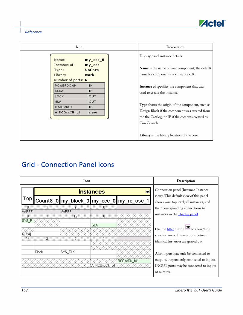
Reference
158 Libero IDE v9.1 User’s Guide
Icon Description
Display panel instance details. Name is the name of your component; the default name for components is <instance>_0. Instance of specifies the component that was used to create the instance. Type shows the origin of the component, such as Design Block if the component was created from the the Catalog, or IP if the core was created by CoreConsole. Library is the library location of the core.
Grid - Connection Panel Icons
Icon Description
Connection panel (Instance-Instance view). This default view of this panel shows your top level, all instances, and their corresponding connections to instances in the Display panel.
Use the filter button to show/hide your instances. Intersections between identical instances are grayed out. Also, inputs may only be connected to outputs, outputs only connected to inputs. INOUT ports may be connected to inputs or outputs.
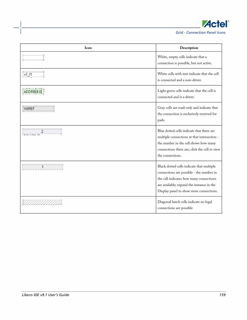
Grid - Connection Panel Icons
Libero IDE v9.1 User’s Guide 159
Icon Description
White, empty cells indicate that a connection is possible, but not active.
White cells with text indicate that the cell is connected and a non-driver.
Light green cells indicate that the cell is connected and is a driver.
Gray cells are read-only and indicate that the connection is exclusively reserved for pads.
Blue dotted cells indicate that there are multiple connections at that intersection - the number in the cell shows how many connections there are; click the cell to view the connections.
Black dotted cells indicate that multiple connections are possible - the number in the cell indicates how many connections are available; expand the instance in the Display panel to show more connections.
Diagonal hatch cells indicate no legal connections are possible

Reference
160 Libero IDE v9.1 User’s Guide
Icon Description
List of ports available to connect. The intersection of an instance in the Display panel and an instance in the Connection panel enables a drop-down menu. Select the pin you want to use to connect the two instances from the drop-down menu. Icons in the drop-down menu represent whether the connection is a connected input, output, master, or slave. See the Display panel icon list for more information.
Schematic Symbols
Icon Description
Schematic input icon
Schematic output icon
Schematic inout icon
Schematic input icon (multiple addresses)
Schematic connection icon
Schematic connection icon (multiple connections)

Using the HDL Editor
Libero IDE v9.1 User’s Guide 161
Icon Description
Schematic inverter icon; hover your mouse over the inverter symbol in the schematic view for more information on the state of your inverter. An inverter symbol does not necessarily indicate that all your pins are inverted.
Using the HDL Editor The HDL Editor is a text editor designed for editing HDL source files. In addition to regular editing features, the editor provides a syntax checker.
You can have multiple files open at one time in the HDL Editor workspace. Click the tabs to move between files.
CoreConsole only: If you use the template created by CoreConsole to instantiate the top level of the CoreConsole project, you must create a new HDL source file and copy the content of the template. If you do not, Libero IDE overwrites the file if you re-import a CoreConsole project.
Editing
Editing functions are available in the Edit menu. Available functions include cut, copy, paste, find, and replace. These features are also available in the toolbar.
Saving
You must save your file to add it to your Libero IDE project. Select Save in the File menu, or click the Save icon in the toolbar.
Printing
Print and Print Preview functions are available from the File menu and the toolbar.
Note: Note: To avoid conflicts between changes made in your HDL files, Actel recommends that you use one editor for all of your HDL edits.
Creating New HDL Files To create an HDL file:
1. Open your project.
2. From the File menu, choose New.
3. Click VHDL and type a file name in the Name field. Click OK. (Do not enter a file extension; Libero adds one for you.) The HDL Editor workspace opens.
4. After creating your HDL file, save your file to the project by selecting Save from the File menu. Your HDL file is saved to your project and shown in the Files tab.

Reference
162 Libero IDE v9.1 User’s Guide
Opening an HDL Source File To open an HDL source file:
1. From the File menu, choose New.
2. From Files of Type, select HDL File (*.vhd, *.vhdl).
3. In Look in, navigate to the HDL file directory.
4. Select your file and click Open. Libero IDE opens your file in the HDL Editor.
Importing HDL Source Files Import your HDL file into your project just as you would any source file.
To import an HDL source file:
1. From the File menu, choose Import Files.
2. In Files of type, select the file type.
3. In Look in, navigate to the drive/folder that contains the file.
4. Select the file to import and click Open.
HDL Syntax Checker After you are done creating your HDL file, use the HDL Syntax Checker to help validate an HDL file after editing the HDL code.
To run the syntax checker:
1. In the Libero IDE Files tab, right-click an HDL file and choose Check HDL File.
2. The syntax checker parses the selected HDL file and looks for typographical mistakes and syntactical errors. Warning and error messages for the HDL file appear in the Libero IDE Log Window.
Commenting Text You can comment text as you type in the HDL Editor, or you can comment out blocks of text by selecting a group of text and applying the Comment command.
To comment or uncomment out text:
1. Type your text.
2. Select the text.
3. From the Edit menu or right-click menu, choose CommentOut or Uncomment.
Using Design Block Cores from the Catalog - HDL Entry Use cores to:
ViewDraw AE
Libero IDE v9.1 User’s Guide 163
• Create high-level modules, such as counters, multiplexers, multipliers, etc. that are optimized for Actel FPGAs.
• Create system-level building blocks, such as filters, FIFOs, and memories.
These can be instantiated into your schematic, Verilog design, or HDL design.
To use Design Blocks with your HDL design:
1. From the Libero IDE File menu, choose New.
2. In the New File dialog box, select the core, type a name, and click OK. The core configurator opens.
3. Select your core type. The appropriate options appear. Select a tab and fill in the fields. Click Generate.
4. In the Save As dialog box, leave the default selections and click Save. The file is added to your Libero IDE project; it is shown in the Hierarchy tab.
5. Instantiate the module in your HDL design.
ViewDraw AE ViewDraw AE is a special version of ViewDraw. Use it for schematic entry with Libero IDE.
CoreConsole only: If you use the template created by CoreConsole to instantiate the top level of the CoreConsole project, you must create a new HDL source file and copy the content of the template. If you do not, Libero IDE overwrites the file if you re-import a CoreConsole project.
ViewDraw for Actel Schematics Guidelines
Adding and Removing Ports from an Existing Schematic You may wish to add or remove ports from an existing schematic. To do so:
1. From the Libero Project Manager, right-click the symbol and select Delete from Disk and Project.
2. In ViewDraw, open your schematic and select Add/remove ports.
3. Click Save and Check.
4. Re-create the symbol from within the Libero Project Manager.
5. Update the schematics, instantiating the modified symbol.
Naming Conventions • Project names must be less than 8 characters. For example: my_top
• Do not use spaces, especially in:
• Project names
• Instance names
• Net names
Reference
164 Libero IDE v9.1 User’s Guide
• Port names
• Schematic names
• Stimulus file names
• HDL names
• Do not use any special characters in any of your naming, such as: ~ ! @ # $ % ^ & * ( ) = + { } | \ / < > ? ` ‘ “ “, . or spaces.
• The tool does not support the “inverted” net property.
• If you want to rip out scalar bits from a bus, use [] for scalar bit naming. For example, Bus[15], Bus[14], …, Bus[0]. If a bus DATA[15:0] is declared in the schematic then you can also use net names DATA5, DATA10 etc. to rip the DATA bus. If net DATA5 is unrelated to the DATA bus then you need to add a letter at the end of the net name, e.g. DATA5N.
• Do not use numbers at the beginning or the end of any names. Scalar bit Bus1[15] of Bus1[15:0] can be confused with Scalar bit Bus11[5] of Bus11[15:0] during netlist generation.
• If you want to use numbers to distinguish related nets, use numbers followed by letters at the end, for example: NET1N, or Bus1A[15:0].
• Do not use naming “Bus[0:3][0:3]” to implement scalar bits. The second bus dimension is not supported. Instead use: Bus[00], Bus[01]…, Bus[10], Bus[11]….
• Multi-dimensional busses are not supported. For example, do not use naming "Bus[0:3][0:3]" in ViewDraw AE.
• Do not name any component with the same name as Actel library components.
Finding an Inverted Signal in a Schematic When looking for an inverted signal, use '~signal_name' instead of 'signal_name', since in schematic and wir files, inverted signals are saved as '~signal_name'. Use the menu option Edit > Select to find the signal.
Using Connectors and I/O Pads • Use hierarchy connectors in any schematic design for any external ports and any ports of sub-modules.
• You can insert I/O pads automatically by running Synthesis or Optimize & Insert Pads from Libero IDE. For schematic designs, which only use Actel primitives (no HDL blocks), you can manually insert all I/O pads. This is in case you do not want to go through the synthesis flow.
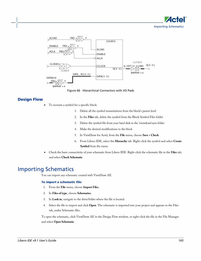
Importing Schematics
Libero IDE v9.1 User’s Guide 165
Figure 66 · Hierarchical Connectors with I/O Pads
Design Flow • To recreate a symbol for a specific block:
1. Delete all the symbol instantiations from the block’s parent level
2. In the Files tab, delete the symbol from the Block Symbol Files folder
3. Delete the symbol file from your hard disk in the \viewdraw\sym folder
4. Make the desired modifications to the block
5. In ViewDraw for Actel, from the File menu, choose Save + Check
6. From Libero IDE, select the Hierarchy tab. Right-click the symbol and select Create Symbol from the menu
• Check the basic connectivity of your schematic from Libero IDE. Right-click the schematic file in the Files tab, and select Check Schematic.
Importing Schematics You can import any schematic created with ViewDraw AE.
To import a schematic file:
1. From the File menu, choose Import Files.
2. In Files of type, choose Schematics.
3. In Look in, navigate to the drive/folder where the file is located.
4. Select the file to import and click Open. The schematic is imported into your project and appears in the Files tab, under Schematic files.
To open the schematic, click ViewDraw AE in the Design Flow window, or right-click the file in the File Manager and select Open Schematic.
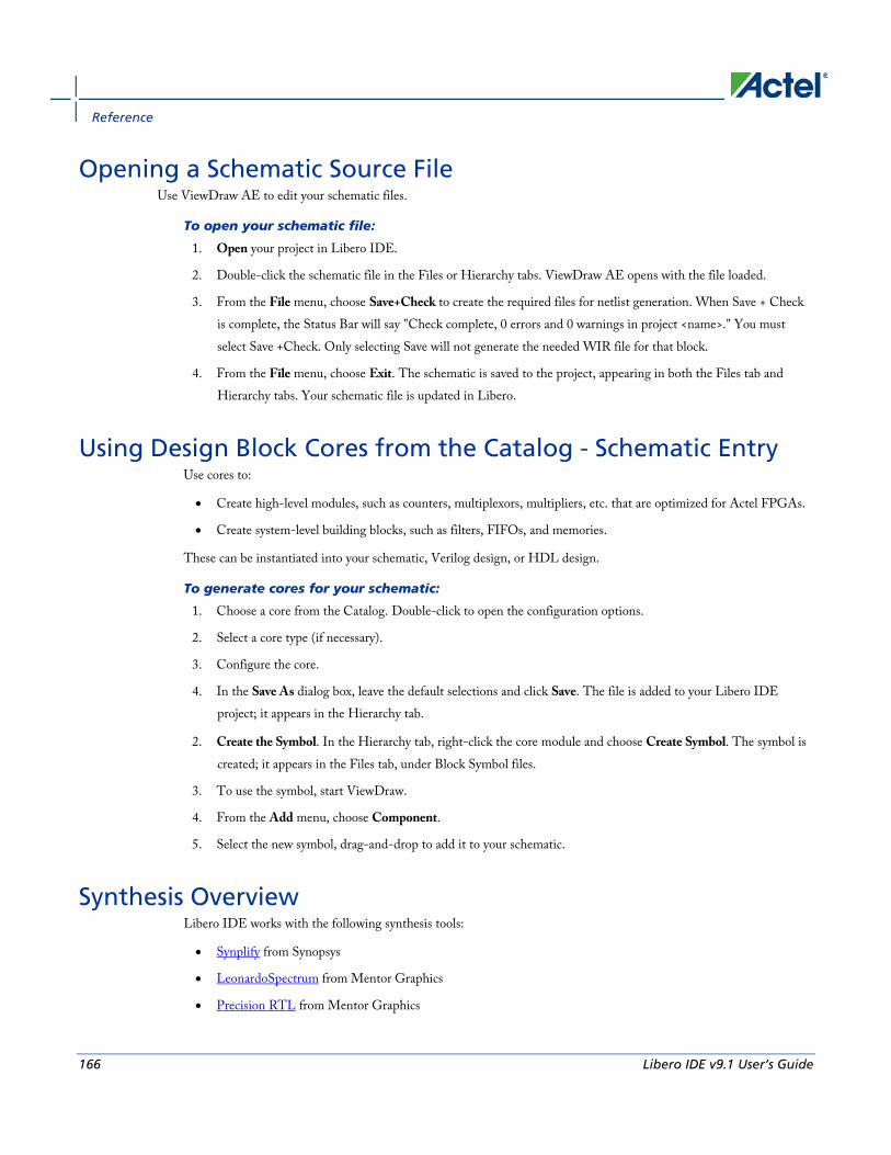
Reference
166 Libero IDE v9.1 User’s Guide
Opening a Schematic Source File Use ViewDraw AE to edit your schematic files.
To open your schematic file:
1. Open your project in Libero IDE.
2. Double-click the schematic file in the Files or Hierarchy tabs. ViewDraw AE opens with the file loaded.
3. From the File menu, choose Save+Check to create the required files for netlist generation. When Save + Check is complete, the Status Bar will say "Check complete, 0 errors and 0 warnings in project <name>." You must select Save +Check. Only selecting Save will not generate the needed WIR file for that block.
4. From the File menu, choose Exit. The schematic is saved to the project, appearing in both the Files tab and Hierarchy tabs. Your schematic file is updated in Libero.
Using Design Block Cores from the Catalog - Schematic Entry Use cores to:
• Create high-level modules, such as counters, multiplexors, multipliers, etc. that are optimized for Actel FPGAs.
• Create system-level building blocks, such as filters, FIFOs, and memories.
These can be instantiated into your schematic, Verilog design, or HDL design.
To generate cores for your schematic:
1. Choose a core from the Catalog. Double-click to open the configuration options.
2. Select a core type (if necessary).
3. Configure the core.
4. In the Save As dialog box, leave the default selections and click Save. The file is added to your Libero IDE project; it appears in the Hierarchy tab.
2. Create the Symbol. In the Hierarchy tab, right-click the core module and choose Create Symbol. The symbol is created; it appears in the Files tab, under Block Symbol files.
3. To use the symbol, start ViewDraw.
4. From the Add menu, choose Component.
5. Select the new symbol, drag-and-drop to add it to your schematic.
Synthesis Overview Libero IDE works with the following synthesis tools:
• Synplify from Synopsys
• LeonardoSpectrum from Mentor Graphics
• Precision RTL from Mentor Graphics

Post-Synthesis Files
Libero IDE v9.1 User’s Guide 167
While LeonardoSpectrum and Precision RTL are not part of the Libero IDE package, they can be integrated to work with Libero IDE. You can also integrate different versions of Synplify. To integrate tools, add them to your project profile.
Post-Synthesis Files Post-synthesis files include:
• <top>.edn - EDIF netlist file; used for post-synthesis simulation in the Project Manager; also used by Designer to generate back-annotated files and complete layout
• <top>.adb - Designer project file, automatically generated by the Project Manager.
• <top>.vhd - Simulation file, automatically generated by the Project Manager.
To generate your EDIF netlist, use your Synthesis tool. You can also import your EDIF netlist named <top>.edn.
Icons:
• (Green check) - Files are current; you can use the file for simulation or place-and-route.
• (Yellow exclamation) - Files are out-of-date;something has changed since you created your post-synthesis file (you may have modified the source, family, default synthesis tool, package, etc.) Re-run synthesis to update the file. You may use the out-of-date file for simulation or place-and-route if you wish.
Synplify AE and Synplify Pro AE Libero IDEs integrated synthesis tool, Synplify Pro AE from Synopsys, takes your Verilog or VHDL Hardware Description Language source as input and outputs an optimized EDIF and HDL netlist.
Set your tool profile to the synplifypro.exe to take advantage of this tool.
Note: Note: See the Actel Attribute and Directive Summary in the Synplify online help for a list of attributes related to Actel devices.
See Also Synthesizing your design with Synplify
Synthesizing Your Design with Synplify 1. In the Libero IDE, right-click the HDL file in the Files tab, or the top-level schematic for mixed schematic-
HDL designs in the Hierarchy, and select Synthesize. Synplify starts and loads the appropriate design files, with a few pre-set default values.
2. From Synplify’s Project menu, choose Implementation Options.
3. Set your specifications and click OK.
Reference
168 Libero IDE v9.1 User’s Guide
4. Deactivate synthesis of the defparam statement. The defparam statement is only for simulation tools and is not intended for synthesis. Embed the defparam statement in between translate_on and translate_off synthesis directives as follows : /* synthesis translate_off */ defparam M0.MEMORYFILE = "meminit.dat" /*synthesis translate_on */ // rest of the code for synthesis
5. Click the RUN button. Synplify compiles and synthesizes the design into an EDIF, *.edn, file. Your EDIF netlist is then automatically translated by Libero into an HDL netlist. The resulting *edn and *.vhd files are visible in the File Manager, under Implementation Files.
Should any errors appear after you click the Run button, you can edit the file using the Synplify editor. Double-click the file name in the Synplify window showing the loaded design files. Any changes you make are saved to your original design file in Libero.
6. From the File menu, choose Exit to close Synplify. A dialog box asks you if you would like to save any settings that you have made while in Synplify. Click Yes.
Note: Note: See the Actel Attribute and Directive Summary in the Synplify online help for a list of attributes related to Actel devices.
Note: To add a clock constraint in Synplify you must add "n:<net_name>" in your SDC file. If you put the net_name only, it does not work.
See Also Synplify AE
Synopsys Identify Debugger Libero IDE integrates the Identify RTL debugger tool. It enables you to probe and debug your FPGA design directly in the source RTL. Use Identify software when the design behavior after programming is not in accordance with the simulation results.
To open the Identify RTL debugger, click the Debugging button in the Project Flow window.
Identify features:
• Instrument and debug your FPGA directly from RTL source code .
• Internal design visibility at full speed.
• Incremental iteration - Design changes are made to the device from the Identify environment using incremental compile. You iterate in a fraction of the time it takes route the entire device.
• Debug and display results - You gather only the data you need using unique and complex triggering mechanisms.
You must have both the Identify RTL Debugger and the Identify Instrumentor to run the debugging flow outlined below.

Integrating Precision RTL
Libero IDE v9.1 User’s Guide 169
To use the Identify debugger:
1. Create your source file (as usual) and run pre-synthesis simulation.
2. (Optional) Run through an entire flow (Synthesis - Designer - FlashPro) without starting Identify.
3. Click the Synthesis Synplify button in the Libero IDE to launch Synplify. From within Synplify, launch the Identify Instrumentor.
4. From the Instumentor UI specify the sample clock, the breakpoints, and other signals to probe. Synplify creates a new synthesis implementation. Synthesize the design.
5. In Libero IDE, select the edif netlist of the Identify implementation you want to use in the flow.
6. Run Designer and FlashPro with the edif netlist you created with the Identify implementation.
7. Click the Debugging button in the Design Flow window to launch the Identify Debugger.
The Identify RTL Debugger, Synplify, and FlashPro must be synchronized in order to work properly. See the Release Notes for more information on which versions of the tools work together.
Integrating Precision RTL Libero IDE supports Precision RTL from Mentor Graphics.
To integrate Precision RTL with your Libero IDE project:
1. From the Options menu, choose Profile. The Project Profile dialog box appears.
2. Click Add and select Synthesis. The Add Tool dialog box appears.
3. Enter a name. This is the name that appears in the Project Profile dialog box.
4. Select Precision RTL.
5. Enter the location of Precision RTL and any additional parameters.
6. Click OK.
7. Select Precision RTL in the Project Profile dialog box and click OK.
8. Click Precision RTL in the Project Manager Project Flow window to start Precision RTL.
Starting Precision RTL Before you can start Precision RTL you must add it to your project profile.
To start Precision RTL to run synthesis:
1. In Libero, right-click the HDL file in the Files tab or the top-level schematic for mixed schematic-HDL designs in the Hierarchy, and select Synthesize. Precision starts.
2. (Optional) Click SetupDesign to enter clock frequency, input delays and output delays.
3. (Optional) Click Constraint if you want to import a constraint file (*.sdf).
4. Click Compile if you want to compile the design first.

Reference
170 Libero IDE v9.1 User’s Guide
5. If compile runs without error, click Synthesize to optimize the design for your target technology. To investigate errors in the log window, click the red error icon next to the error. An HDL Text Editor opens and the part of the HDL text which is the source of the error is automatically highlighted for you to modify. Click Save to save the changes you have made to the HDL text. Rerun Synthesis to get a successful run.
6. Click Synthesize. Precision RTL runs compile and then synthesizes your design.
7. The synthesized netlist (EDIF format) is visible under Implementation Files in the Files tab.
8. From the File menu, select Exit to close Precision RTL. A dialog box asks you if you would like to save any settings that you have made while in Precision. Click Yes to save the Precision project file (*.psp).
See Also Integrating Precision RTL
Profiles Dialog
Integrating LeonardoSpectrum Libero IDE supports LeonardoSpectrum from Mentor Graphics.
To integrate LeonardoSpectrum with your Libero IDE project:
1. From the Options menu, choose Profile. The Project Profile dialog box appears.
2. Click Add and select Synthesis. The Add Synthesis Tool dialog box appears.
3. Enter a name. This is the name that appears in the Project Profile dialog box.
4. Select LeonardoSpectrum.
5. Enter the location of LeonardoSpectrum and any additional parameters.
6. Click OK.
7. Select LeonardoSpectrum in the Project Profile dialog box and click OK.
8. Click LeonardoSpectrum in the Project Flow window to start LeonardoSpectrum.
See Also Profiles Dialog
Synthesizing Your Design with LeonardoSpectrum Before you can start Precision RTL you must add it to your project profile.
To synthesizing your design with LeonardoSpectrum:
1. In Libero, right-click the HDL file in the Files tab, or the top-level schematic for mixed schematic-HDL designs in the Hierarchy tab, and choose Synthesize. LeonardoSpectrum starts.
2. The Input Box is blank. Hit the Enter key on the keyboard and all the design files are loaded into the Input Box.
3. From the Tools menu, choose Options.

Integration Issues
Libero IDE v9.1 User’s Guide 171
4. Deselect Automatically save and Restore Current Work Directory option.
5. Enter the Clock Frequency if you want to constrain the design.
6. Use the slide bar to select the level of Optimize Effort.
7. Click RunFlow. Click the red error icon next to the error for Information about errors. The HDL Text Editor opens and the part of the HDL text which is the source of the error is automatically highlighted for you to modify.
8. Click Save to save the changes you have made to the HDL text. Rerun Synthesis to get a successful run. The synthesized netlist is in EDIF format and is visible under Implementation Files in the Libero IDE Files tab tab.
9. From the File menu, choose Exit to close LeonardoSpectrum. A dialog box asks you if you would like to save any settings that you have made while in LeonardoSpectrum. Click Yes to save the LeonardoSpectrum project file (*.lsp).
Integration Issues Some workarounds are required when using LeonardoSpectrum with Libero IDE.
All versions of LeonardoSpectrum
• LeonardoSpectrum log files are misplaced: From the Tools menu, choose Options, and SessionSettings. Deselect Automatically Save and Restore Current Working Directory. This box must be unchecked in order for your log files to be passed back to Libero properly.
LeonardoSpectrum v2003a Only
• LeonardoSpectrum starts with empty windows: When you first open LeonardoSpectrum from Libero, the Input window is blank and the output file is not specified. Also, the wrong family appears in the Technology window. To fix this, simply place your cursor in the transcript window and press Enter. All windows are updated.
WaveFormer ProTM WaveFormer Pro can be used to generate VHDL and Verilog stimulus-based testbenches for Libero IDE. WaveFormer Pro fits into the Libero IDE, automatically extracting signal information from your HDL design files and producing HDL test bench code that can be used for VHDL or Verilog simulation.
WaveFormer Pro generates VHDL and Verilog testbenches from drawn waveforms. Use WaveFormer Pro to generate the following:
• Reactive testbenches
• VHDL transport testbench (*.vhd) that uses assignment statements
• VHDL wait testbench (*.vhd) that uses wait statements
• Verilog (*.v) file with Verilog stimulus statements
Reference
172 Libero IDE v9.1 User’s Guide
Update your project Profile to add WaveFormer Pro to your Libero IDE. See the Setting your Project Profile help topic for more information.
Note: Note: WaveFormer Pro comes with its own online help. After starting WaveFormer Pro, click the Help menu.
Creating Your Testbench with WaveFormer Pro WaveFormer Pro generates VHDL and Verilog testbenches from drawn waveforms. Create your testbench after you are done creating your design and wish to perform simulation. If you do not have WaveFormer Pro, create your testbench with an alternative third-party tool.
There are five basic steps for creating testbenches using WaveFormer Pro and Libero IDE. These steps are described in detail in the following sections.
To create a testbench using WaveFormer Pro:
1. Click WaveFormer Pro in the Project Flow window. WaveFormer Pro starts and your signal information is imported automatically.
2. Using WaveFormer Pro, draw the waveforms to describe the testbench.
3. From the Export menu, choose Export Timing Diagram and choose the save type as *.tim or *.btim. This saves the waveforms.
4. (Optional) Add VHDL Libraries and Use Clauses for VHDL export. These libraries or packages can be included using the VHDL Libraries and Use Clauses dialog. From the Options menu, select the VHDL Libraries and Use Clauses menu item to open this dialog.
5. From the Export menu, choose Export Timing Diagram and choose the type of file to generate. To generate a plain testbench model (which does not instantiate your model under test), choose one of the VHDL or Verilog scripts. To simulate with the testbench model, you will need to write a top-level model that instantiates the testbench model and the model under test. Below is a list of VHDL and Verilog testbench generation scripts:
• VHDL Wait (*.vhd)s
• VHDL Transport (*.vhd)s
• Verilog
5. From the File menu, choose Exit.
Note: Note: If you added extra signals to the testbench and do not want to export those signals, then double-click the signal’s names to open the Signals Properties dialog and clear the Export check box.
Synplify always changes the data type to std_logic or std_logic_vector in the post_synthesis netlist. If your top-level entity port is not std_logic or std_logic_vector and you need to run post-synthesis or post-layout simulation, you need to change the data type in WFL.
To create two testbenches:
1. Open the *.tim file and select the special data type signal, right-click and choose Edit Selected Signal.

ModelSimTM AE
Libero IDE v9.1 User’s Guide 173
2. Choose std_logic or std_logic_vector under VHDL and click Save.
ModelSimTM AE ModelSim Actel Edition (AE) is a custom edition of ModelSim PE that is integrated into Libero's design environment. ModelSim for Actel is an OEM edition of Model Technology Incorporated’s (MTI) tools. ModelSim for Actel supports VHDL or Verilog. It only works with Actel libraries and is supported by Actel.
Other editions of ModelSim are supported by Libero IDE. To use other editions of ModelSim with Libero IDE, simply do not install ModelSim AE from the Libero CD.
Note: Note: ModelSim for Actel comes with its own online help and documentation. After starting ModelSim, click the Help menu.
Setting Simulation Options You can set a variety of simulation options for your project.
To set your simulation options:
1. From the Options menu, choose ProjectSettings.
2. Click Simulation.
3. Select your options and click OK.
4. Use automatic Do file: Select if you do not want Libero to initialize ModelSim.
5. User defined Do file: Enter the Do file name or click the browse button.
Automatic Do file content
• Include Do file - Select to execute the wave.do or other specified Do file. Use the wave.do file to customize the ModelSim Waveform window display settings.
• Simulation Run Time - Specify how long the simulation should run in nanoseconds. If the value is 0, or if the field is empty, there will not be a run command included in the run.do file.
• Testbench module/entity name - Specify the name of your testbench entity name. Default is “testbench,” the value used by WaveFormer Pro.
• Top Level instance name in the testbench - Default is <top_0>, the value used by WaveFormer Pro. The Libero IDE Project Manager replaces <top> with the actual top level macro when you run ModelSim.
• Vsim Command Type - Select Minimum (Min), Typical (Typ), or Maximum (Max).
• Resolution: The default is family-specific, but you can customize it to fit your needs. Some custom simulation resolutions may not work with your simulation library. For example, simulation resolutions above 1 ns will cause errors if you are using SX-A devices (the simulation errors out because of an infinite zero-delay loop). Consult your simulation help for more information on how to work with your simulation library and detect infinite zero-delay loops caused by high resolution values.

Reference
174 Libero IDE v9.1 User’s Guide
Family Default Resolution
ACT1, ACT2, ACT3 1 ns
MX 1 ns
DX 1 ns
SX, SX-A 1 ns
eX 1 ns
Axcelerator 1 ps
ProASIC 1 ps
ProASICPLUS 1 ps
ProASIC3/E 1 ps
IGLOO/e 1 ps
Fusion 1 ps
• Vsim additional options: Text entered in this field is added to the vsim command.
• ModelSim library path: Enables you to choose the ModelSim default library for your device, or to specify your own ModelSim library. Enter the full pathname of your own library to use it for simulation.
• Generate VCD file: Select this checkbox to have ModelSim automatically generate a VCD file based on the current simulation. VCD files can be imported into Designer and used in SmartPower. For best results, we recommend that a postlayout simulation be used to generate the VCD.
• VCD filename: Specify the name of the VCD file that will be automatically generated by ModelSim
• Default: Restores factory settings.
Selecting a Stimulus File for Simulation Before running simulation, you must associate a testbench. If you attempt to run simulation without an associated testbench, the Project Manager asks you to associate a testbench or open ModelSim without a testbench.
To associate a stimulus:
1. Run simulation or right-click the top level module in the Hierarchy Menu and select Organize Stimulus File from the right-click menu. The Organize Stimulus dialog box appears.

Selecting Additional Modules for Simulation
Libero IDE v9.1 User’s Guide 175
2. Associate your testbench(es):
In the Organize Stimulus dialog box, all the stimulus files in the current Libero IDE project appear in the left Stimulus Files in the Project list box. Files already associated with the block appear in the Associated Files list box.
In most cases you will only have one testbench associated with your block. However, if you want simultaneous association of multiple testbench files for one simulation session, as in the case of PCI cores, add multiple files to the Associated Files dialog box.
To add a testbench: Select the testbench you want to associate with the block in the Stimulus files in the project list box and click Add to add it to the Associated Files list.
To remove a testbench: To remove or change the file(s) in the Associated files list box, select the file(s) and click Remove.
To order testbenches: Use the up and down arrows to define the order you want the testbenches compiled. The top level-entity should be at the bottom of the list.
3. When you are satisfied with the Associated File(s) list, click OK. A checkmark appears next to WaveFormer Pro in the Project Flow window to let you know that a testbench has been associated with the block.
Selecting Additional Modules for Simulation Libero IDE passes all the source files related to the top-level module to simulation .
If you need additional modules in simulation, right-click the module name in the Hierarchy and select Properties from the shortcut menu. Select the Included for Simulation check box to pass the file to simulation.
You must repeat this for each additional module you wish to pass to simulation.
Performing Functional Simulation To perform functional simulation:
1. Create your testbench.
2. Right-click the top level module in the Hierarchy tab and choose Organize Stimulus File from the right-click menu.
In the Organize Stimulus dialog box, all the stimulus files in the current Libero IDE project appear in the Stimulus Files in the Project list box. Files already associated with the block appear in the Associated Files list box.
In most cases you will only have one testbench associated with your block. However, if you want simultaneous association of multiple testbench files for one simulation session, as in the case of PCI cores, add multiple files to the Associated Files dialog box.
To add a testbench: Select the testbench you want to associate with the block in the Stimulus Files in the Project list box and click Add to add it to the Associated Files list.
To remove a testbench: To remove or change the file(s) in the Associated Files list box, select the file(s) and click Remove.
To order testbenches: Use the up and down arrows to define the order you want the testbenches compiled.

Reference
176 Libero IDE v9.1 User’s Guide
3. When you are satisfied with the Associated File(s) list, click OK.
4. Start ModelSim AE by doing one of the following:
• Right-click the top level module in the Design Hierarchy window and choose Run Pre-Synthesis Simulation or Run Post-Synthesis Simulation.
• Click ModelSim Simulation in the Project Flow Window.
ModelSim starts and compiles the appropriate source files. When the compilation completes, the simulator runs for 1 µs and the Wave window opens to display the simulation results.
5. Scroll in the Wave window to verify that the logic of your design functions as intended. Use the zoom buttons to zoom in and out as necessary.
6. From the File menu, select Quit.
Performing CoreConsole Functional Simulation Libero overwrites all the existing files of the Core when you import a CoreConsole project (including testbenches). Save copies of your CoreConsole project stimulus files with new names if you wish to keep them.
You must import a CoreConsole BFM file into the Libero IDE in order to complete functional simulation (the BFM is a stimulus file that you can edit to extend the testbench). VEC files are generated automatically from the BFM when you run ModelSim.
The Project Manager overwrites your BFM file if you re-import your CoreConsole project. Edit and save your BFM outside the Libero IDE project to prevent losing your changes. After you re-import your core-console project, you can import your modified BFM again.
To perform functional simulation of a CoreConsole project:
1. Right-click a stitched module of the CoreConsole project or the top level of the CoreConsole project and select Set as root.
3. Start ModelSim AE by doing one of the following:
• Right-click the top level module in the Design Hierarchy window and choose Run Pre-SynthesisSimulation,Run Post-Synthesis Simulation.
• Click ModelSim Simulation in the Project Flow Window.
ModelSim starts and compiles the appropriate source files. When the compilation completes, the simulator runs for 1 µs and the Wave window opens to display the simulation results.
5. Scroll in the Wave window to verify that the logic of your design functions as intended. Use the zoom buttons to zoom in and out as necessary.
6. From the File menu, select Quit.

Performing Timing Simulation
Libero IDE v9.1 User’s Guide 177
Performing Timing Simulation The steps for performing functional and timing simulation are nearly identical. Functional simulation is performed before place-and-route and simulates only the functionality of the logic in the design. Timing simulation is performed after the design has gone through place-and-route and uses timing information based on the delays in the placed and routed designs.
Timing simulation includes much more detailed timing information for the targeted device. Timing simulation requires a testbench.
To perform timing simulation:
1. If you have not done so, back-annotate your design and create your testbench.
2. Right-click the top level module in the Hierarchy and choose Organize Stimulus File from the right-click menu.
In the Organize Stimulus dialog box, all the stimulus files in the current Libero IDE project appear in the Stimulus Files in the Project list box. Files already associated with the block appear in the Associated Files list box.
In most cases, you will only have one testbench associated with your block. However, if you want simultaneous association of multiple testbench files for one simulation session, as in the case of PCI cores, add multiple files to the Associated Files dialog box.
To add a testbench: Select the testbench you want to associate with the block in the Stimulus Files in the Project list box and click Add to add it to the Associated Files list.
To remove a testbench: To remove or change the file(s) in the Associated Files list box, select the file(s) and click Remove.
To order testbenches: Use the up and down arrows to define the order you want the testbenches compiled.
3. When you are satisfied with the Associated File(s) list, click OK.
4. Click ModelSim Simulation in the Project Flow window. The ModelSim simulator starts and compiles the source files. When the compilation completes, the simulator runs for 1 µS and a Wave window opens to display the simulation results.
5. Scroll in the Wave window to verify the logic works as intended. Use the cursor and zoom buttons to zoom in and out and measure timing delays. If you did not create a testbench with WaveFormer Pro, you may get error messages with the vsim command if the instance names of your testbench do not follow the same conventions as WaveFormer Pro. Ignore the error message and type the correct vsim command.
6. When you are done, from the File menu, choose Quit.

Welcome to Designer
178 Libero IDE v9.1 User’s Guide
Welcome to Designer
The Designer interface offers both automated and manual flows, with the push-button flow achieving the optimal solution in the shortest cycle.
Actel's Designer software is integrated with the Libero IDE Project Manager. Use the Designer software to implement your design.
To implement your design:
1. Right-click the top level module in the Hierarchy and choose Run Designer, or click Designer in the Project Flow window. Designer starts and loads your files from Libero.
2. Set up your device. From the Tools menu, select Device Selection. In the Device Selection Wizard, select the die, package, speed grade, voltage, and operating conditions. Make your selections and click Next to complete the steps
3. In Designer, click Compile in the design flow window. The log window displays the utilization of the selected device. When compile has completed, the Compile box in the Design Flow window turns green.
4. Once you have successfully compiled your design, you can use Designer’s User's tool to optimize your design. To start a tool, simply click it in the flow tree. The tools include:
Tool Function Supported Families
PinEditor Package-level floorplanner and I/O attribute editor
All
ChipPlanner Logic viewer, placement- and floorplanning tool
IGLOO, ProASIC3, SmartFusion, Fusion, ProASICPLUS, ProASIC, Axcelerator, RTAX-S, eX, and SX-A
ChipEditor Logic viewer and placement tool
SX, MX, 3200DX, ACT3, ACT2, ACT1
NetlistViewer Design schematic viewer All
SmartPower Power analysis tool IGLOO, ProASIC3, SmartFusion, Fusion, ProASICPLUS, ProASIC, Axcelerator, RTAX-S, eX, and SX-A
SmartTime and Timer
Static timing analysis and constraints editor
All

Starting Designer
Libero IDE v9.1 User’s Guide 179
Tool Function Supported Families
(SmartTime only)
I/O Attribute Editor
Edit I/O attributes, layout IGLOO, ProASIC3, SmartFusion, Fusion, ProASICPLUS, ProASIC, Axcelerator, RTAX-S, eX, and SX-A
5. Click Layout in the Design Flow Window to place-and-route your design.
6. Click Back-Annotate in the Design Flow Window. Choose SDF as CAE type and appropriate simulation language. Select Netlist in the Export Additional Files area and Click OK. If you are exporting files post-layout, Designer exports <top>_ba.vhd and <top>_ba.sdf to your Libero project. The “_ba” is added by Libero to identify these for back-annotation purposes. <top> is the top root name. Pre-layout exported files do not contain “_ba” and are exported simply as *.vhd and *.sdf. The files are visible in the Files tab, under Implementation Files.
7. Click Programming File in the design flow tree if you wish to create a programming file for your design. This step can be performed later after you are satisfied with the back-annotated timing simulation.
8. From the File menu, select Exit. Click Yes to save the design before closing Designer. Designer saves all of the design information in an *.adb file. The <project>.adb file is visible in the File Manger, in the Designer Views folder. To re-open this file at any time, simply double-click it.
Starting Designer To start Designer from Libero IDE:
In the Project Flow window, click Designer Place-and-Route.

Welcome to Designer
180 Libero IDE v9.1 User’s Guide
Starting a New Design To begin a new design session, you must start a new design or open an existing design.
Starting a new design creates an Actel ADB file. ADB files are proprietary Actel project files.
To start a new design:
1. Click Start New Design in the Designer main window, or from the File menu, choose New. This displays the Setup Design dialog box. Note: The Actel ADB file memory requirement is equivalent to 2x the size of the ADB file. If your computer does not have 2x the size of your ADB file's memory available, please make memory available on your hard drive.
2. Setup Design:
• Enter a Design Name. The design name is used in reports and as the default name when saving or exporting files. The Design Name field is disabled when you open

Starting a New Design
Libero IDE v9.1 User’s Guide 181
Designer place-and-route software from the Libero IDE. If you wish to change your design name, from the File menu, choose Save As, and save your file outside of the Libero folder structure.
• If you are creating a Designer Block, select the Enable Designer Block creation checkbox. Designer Blocks are useful if you wish to duplicate design elements. Once you place-and-route and publish your Designer Block you can instantiate the block in as many designs as you like. Note that you cannot program your design in Designer Block mode, only publish the Designer Block files.
• Select an Actel Family from the drop-down menu list.
• Specify a Working Directory. Click Browse to locate a directory. The Working Directory field is disabled when you open Designer place-and-route software from the Libero IDE. If you wish to change your working directory, you must change your filename. To do so, from the File menu, select Save As, and save your file outside of the Libero folder structure.
3. Click OK. The Designer custom design flow window appears. All tools and commands are activated.
Figure 67 · Designer:New Design
Welcome to Designer
182 Libero IDE v9.1 User’s Guide
Opening an existing design To open an existing design:
1. Click Open Existing Design or from the File menu, choose Open. This displays the Open dialog box.
2. Select File. Type the full path name of the .adb file in the File Name box, or select the file from the list.
3. Click Open. The Designer custom design flow window appears and all tools and commands are activated. When you open an existing design, Designer checks to see if you have modified your netlist since the last time you imported the netlist into this design. If you have, Designer prompts you to re-import your netlist.
See Also Starting Designer
Starting a new design
Opening designs created in previous versions Designer can directly open designs created with previous versions of the Designer software.
If your design was created in version 3.1 or earlier, contact the Actel Technical Support department or go to http://www.actel.com/support/ for information on converting your design.
All existing die, package, pin assignments, and place-and-route information is read and maintained. Designs created in previous versions of the software may need library conversions when loaded into the Designer environment. If your design requires this conversion, Designer prompts you to allow the software to update the design to the new library before you attempt to start any of the Designer features.
Opening Locked Files Designer notifies you if a lock has been established on your file. You may receive a warning or an error message when opening a design with a lock.
Warning Designer warns you when opening a design that was not closed properly or may be open somewhere else. You can choose to recover the unsaved edits.

Starting Other Applications from Designer (PC Only)
Libero IDE v9.1 User’s Guide 183
Figure 68 · Warning: Locked File
Error When opening a design, you may receive an error that the file cannot be opened because the lock file is old. You cannot recover any unsaved edits.
To open a design with an old lock file:
1. Go to the design directory.
2. Locate the design *.adb file and corresponding *.lok file.
3. Delete the *.lok file.
4. Return to Designer and open the design.
Starting Other Applications from Designer (PC Only) You can start any application from Designer that you have added to the Tools menu.
To add an application to the Tools menu:
1. From the Tools menu, choose Customize.
2. Enter the application name in the Menu Text area. This text will appear in the Tools command menu.
3. Enter the command to execute, or click the Browse button to select an executable filename. If the location of the command to execute is not in your path, you must include the absolute path when specifying the command.
4. In the Arguments text box, enter the command-line arguments that will be passed to the command when executing.

Welcome to Designer
184 Libero IDE v9.1 User’s Guide
5. In the Initial Directory field, type the absolute path of the directory in which the application will initially be executed.
6. Click Add.
7. When you are finished adding tools, click OK. The application name you added appears in the Tools menu.
To remove an application from the Tools menu:
1. From the Tools menu, choose Customize.
2. Select the application to remove and click Remove.
3. When you are finished removing applications, click OK.
To order applications in the Tools menu:
1. From the Tools menu, choose Customize.
2. Reorder the tools by selecting one at a time and clicking the Move Up or Move Down buttons.
3. Click OK when you are finished. The tools will appear in the Tools menu in the same order as they do in the Menu Contents list box.
About your Installation To display information about your license:
From the Start menu, choose Programs, and then click the Actel software folder and select About Your Installation. The software displays your complete license configuration, all Actel-installed software and versions, as well as your HostID and disk volume serial number.
You can also select License Details from the Help menu in Designer to view your license information.
Directory preferences When executing a command or function such as Open or Save, Designer uses the directory you specify as the start-up directory.
To specify your directory preferences:
1. From the File menu, choose Preferences.
2. Click the Directory tab.
3. Specify your Startup directory.
4. Select your working directory options:
5. To design file's directory when opening design: Select to automatically change directories when opening a design.
6. To design file's directory when saving design: Select to automatically change directories when saving a design.

Updates
Libero IDE v9.1 User’s Guide 185
7. To script file's directory when executing script: Select to automatically change directories when executing a script.
8. Add design name to working directory when creating design: Select to enable a design name folder to be automatically created in the working directory when creating a new design.
9. Click OK.
Updates The Updates tab in the Preferences dialog box allows you to set your automatic software update preferences.
To set your automatic software update preferences:
1. From the File menu, choose Preferences and Updates.
2. Choose one of the following options and click OK.
• Automatically check for updates at startup: Select to be notified of updates when you start Designer.
• Remind me to check for updates at startup: Select to be asked if you want to check for a software update when you start Designer.
• Do not check for updates or remind me at startup: Select if you do not want to check for software updates at startup.
To manually check for software updates, from the Help menu, select Check for Software Updates.
Note: Note: This feature requires an internet connection.
Proxy A Proxy improves access to the Actel server. From the File menu, choose Preferences.
Click the Proxy tab to set your Proxy preferences.
To enable the proxy:
1. Select I use a proxy.
2. Type the proxy name in the text field.
3. Click OK.
File association (PC only) Several programs, including Designer, create files with the ADB extension.
Use the File Association tab in the Preferences dialog box to specify Designer as the default program for files with the .adb extension. Doing so starts Designer whenever a file with the ADB extension is double clicked.
You must have rights to modify the HKEY_CLASSES_ROOT of the registry of the machine to set Designer file association. If you do not have rights to modify the registry, Designer ignores your settings.

Welcome to Designer
186 Libero IDE v9.1 User’s Guide
To associate *.adb files with the Designer application:
1. From the File menu, choose Preferences.
2. Select Check the default file association (*.adb) at startup check box to associate ADB files with the Designer application. Clear the box if you do not want Designer to start when clicking a file with the ADB extension.
3. Click OK.
Setting your Log Window preferences Errors, Warnings, and Informational messages are color-coded in the log window. You can change the default colors by using the log Window tab in the Preferences dialog box.
To change colors in the log window:
1. From the File menu, choose Preferences.
2. Click the Log Window tab in the Preferences dialog box.
3. Select your new default colors and click OK.
The default color settings for the log window are:
Message Type Color
Errors Red
Warnings Light Blue
Informational Black
Linked Dark Blue
The default preference is to Clear the log window automatically. This clears the Designer log window each time you close or open a new design in Designer. Clear the box if you want Designer to leave the log information after you close a design.
PDF Reader (UNIX Only) Use the PDF Reader tab to bring up the online manuals. Enter the default reader’s name with the full path or click Browse.
Web Browser (UNIX Only) Specify the default web browser you wish to use on the UNIX platform. The web browser displays the online help.

Web Browser (UNIX Only)
Libero IDE v9.1 User’s Guide 187
Device Selection
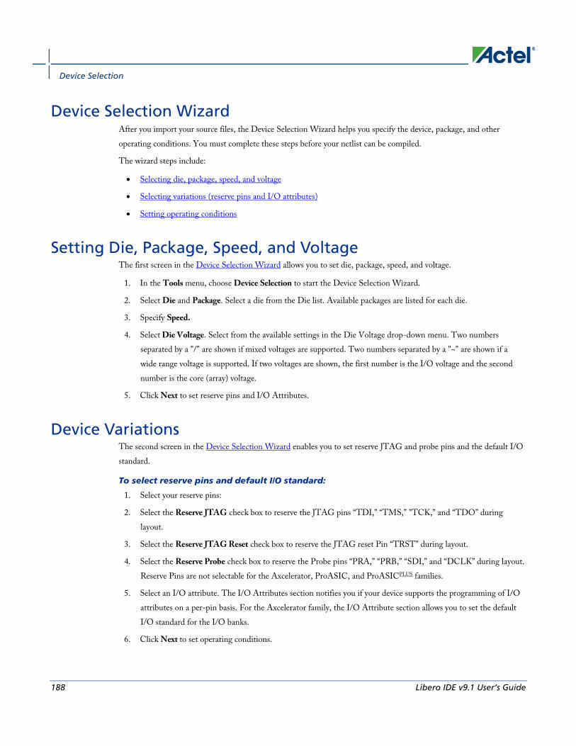
Device Selection
188 Libero IDE v9.1 User’s Guide
Device Selection Wizard After you import your source files, the Device Selection Wizard helps you specify the device, package, and other operating conditions. You must complete these steps before your netlist can be compiled.
The wizard steps include:
• Selecting die, package, speed, and voltage
• Selecting variations (reserve pins and I/O attributes)
• Setting operating conditions
Setting Die, Package, Speed, and Voltage The first screen in the Device Selection Wizard allows you to set die, package, speed, and voltage.
1. In the Tools menu, choose Device Selection to start the Device Selection Wizard.
2. Select Die and Package. Select a die from the Die list. Available packages are listed for each die.
3. Specify Speed.
4. Select Die Voltage. Select from the available settings in the Die Voltage drop-down menu. Two numbers separated by a "/" are shown if mixed voltages are supported. Two numbers separated by a "~" are shown if a wide range voltage is supported. If two voltages are shown, the first number is the I/O voltage and the second number is the core (array) voltage.
5. Click Next to set reserve pins and I/O Attributes.
Device Variations The second screen in the Device Selection Wizard enables you to set reserve JTAG and probe pins and the default I/O standard.
To select reserve pins and default I/O standard:
1. Select your reserve pins:
2. Select the Reserve JTAG check box to reserve the JTAG pins “TDI,” “TMS,” "TCK,” and “TDO” during layout.
3. Select the Reserve JTAG Reset check box to reserve the JTAG reset Pin “TRST” during layout.
4. Select the Reserve Probe check box to reserve the Probe pins “PRA,” “PRB,” “SDI,” and “DCLK” during layout. Reserve Pins are not selectable for the Axcelerator, ProASIC, and ProASICPLUS families.
5. Select an I/O attribute. The I/O Attributes section notifies you if your device supports the programming of I/O attributes on a per-pin basis. For the Axcelerator family, the I/O Attribute section allows you to set the default I/O standard for the I/O banks.
6. Click Next to set operating conditions.

Setting Operating Conditions
Libero IDE v9.1 User’s Guide 189
Setting Operating Conditions Operating Conditions, Step 3 of the Device Selection Wizard, enables you to define the voltage and temperature ranges a device encounters in a working system. The operating condition range entered here is used by SmartTime, the timing report, and the back-annotation function. These tools enable you to analyze worst-, typical-, and best-case timing.
Junction Temperature Select a junction temperature. Supported ranges include:
• Commercial (COM)
• Industrial (IND)
• Military (MIL)
• Automotive
• TGrade1
• TGrade2
• Custom
Consult the Actel Data Sheet, available at http://www.actel.com/techdocs/ds/, to find out which temperature range you should use.
If you select Custom, edit the Best, Typical, and Worst fields. Modify the range to the desired value (real) such that Best < Typical < Worst.
You can calculate junction temperature from values in the Actel Data Sheet, available at http://www.actel.com/techdocs/ds/.
The temperature range represents the junction temperature of the device. For commercial and industrial devices, the junction temperature is a function of ambient temperature, air flow, and power consumption.
For military devices, the junction temperature is a function of the case temperature, air flow, and power consumption. Because Actel devices are CMOS, power consumption must be calculated for each design. For most low power applications (e.g. 250mW), the default conditions are adequate.
Performance decreases approximately 2.5% for every 10 degrees C that the temperature values increase. Refer to the SmartPower online help for more information about power consumption.
Voltage Select a voltage:
• Commercial (COM)
• Industrial (IND)
• Military (MIL)

Device Selection
190 Libero IDE v9.1 User’s Guide
• Automotive
• Custom
If you select Custom, you may enter the values for Best, Typical, and Worst.
For IGLOO, ProASIC3, SmartFusion and Fusion families of devices only
Select a voltage for VCCA and VCCI:
• Commercial (COM)
• Industrial (IND)
• Military (MIL)
• Automotive
• Custom
If you select Custom, you may enter the values for Best, Typical, and Worst.
Wide range voltage for die voltage (VCCA) and VCCI is available for ProASIC3L and 1.2V IGLOO devices. To specify the wide range voltage for VCCI check the Wide Range option and enter the values for Best, Typical, and Worst.
Radiation Derating Conservative post-radiation performance estimates are available for some radiation tolerant devices based upon the number of KRads the device is expected to be subjected to. Radiation effects vary by device lot and may not be completely representative of the lot you are using. Post-radiation timing numbers are only meant to be a guide and are not a guarantee of performance. Customers must consult the specific radiation performance report for the specific lot used. Post radiation exposure estimates currently only affect timing numbers. The SmartPower power analysis tool is not affected by changing the radiation exposure value.
RTSX-S and RTAX-S ONLY - Radiation Derating This option is only available for RTSX-S and RTAX-S devices. The valid range is integer values from 0 to 300, and the units are in KRads. Modifying this selection impacts the timing derating in SmartTime and back-annotating SDF files, so when you modify this value, you must extract a new SDF file from Designer and re-evaluate the timing of your design. It does not affect the device configuration.
Changing Design name and family Design name and family are set when you create a new design. However, you can change this information for existing designs. If you change the family, you must re-import the netlist. Use the following procedure to change the name of a design and the targeted Actel family for the design.
To change the design name or family in Designer:
1. In the Designer Tools menu, choose Setup Design. This displays the Setup Design dialog box.

Changing device information
Libero IDE v9.1 User’s Guide 191
2. Specify the design name and family.
3. Click OK. Refer to the Actel datasheet for your device for family specifications.
You may wish to migrate your SX device to an SX-A device. The SX to SX-A compatible family change option is available in the Device Selection wizard.
To migrate your SX design to SX-A:
1. Open your SX design.
2. From the Designer Tools menu, choose Device Selection.
3. Select SXA from the Change to drop-down menu, and proceed in the Device Selection Wizard to complete the migration. You must re-compile and layout your design to run the Designer User Tools.
Changing device information Device and package information, device variations, and operating conditions are set when you import a netlist and compile a new design. However, you can change this information for existing designs.
To change device information for existing designs:
1. In the Tools menu, choose Device Selection. The Device Selection Wizard appears.
2. Select Die, Package, and Speed Grade and click Next. (You must select a die and package to continue.)
3. Select Device Variations and click Next.
4. Select Operating Conditions and click Finish.
Refer to the Actel FPGA Data Book or call your local Actel Sales Representative for information about device, package, speed grade, variations, and operating conditions.
Compatible Die Change When you change the device, some design information can be preserved depending on the type of change.
Changing Die Revisions If you change the die from one technology to another, all information except timing is preserved. An example is changing an A1020A (1.2µm) to an A1020B (1.0µm) while keeping the package the same.
Device Change Only Constraint and pin information is preserved, when possible. An example is changing an A1240A in a PL84 package to an A1280A in a PL84 package.
Repackager Function (Non-Axcelerator families only) When the package is changed (for the same device), the Repackager automatically attempts to preserve the existing pin and Layout information by mapping external pin names based on the physical bonding diagrams. This always works when changing from a smaller package to a larger package (or one of the same size). When changing to a smaller

Device Selection
192 Libero IDE v9.1 User’s Guide
package, the Repackager determines if any of the currently assigned I/Os are mapped differently on the smaller package. If any of the I/Os are mapped differently, then the layout is invalidated and the unassigned pins identified.
Importing Source Files Source files include your netlist and constraint files.
Source files are files created by outside tools that will be tracked (audited) to better coordinate the design changes. If you wish, you may import some files as auxiliary files. Auxiliary files are not audited, but you do not have to re-compile your design after you import them.
Source Files File Type Extension
Family
EDIF *.ed* All
Verilog *.v All
VHDL *.vhd All
Actel ADL Netlist *.adl All, except ACT1, ACT2, ACT3
Criticality *.crt ACT1, ACT2, ACT3, MX, 1200XL, DX
ProASIC Constraint File
*.gcf ProASICPLUS
Physical Design Constraint File
*.pdc IGLOO, ProASIC3, SmartFusion, Fusion, and Axcelerator
Synopsys Constraint File
*.sdc IGLOO, ProASIC3, SmartFusion, Fusion, ProASICPLUS, ProASIC, Axcelerator, SX-S, SX-A, and eX
CoreConsole Database File
*.cdb* IGLOO, ProASIC3, SmartFusion and Fusion; Designer uses the CDB file to place the CoreMP7 cores and Designer blocks.
The choice of source files is family dependent. Only supported source files are displayed in the Import Source dialog box. If you are working on a new design or if you have changed your netlist, then you must re-import your netlist into Designer.

Importing Source Files
Libero IDE v9.1 User’s Guide 193
To import a source file:
1. From the File menu, choose Import Source Files. This displays the Import Source Files dialog box, as shown in the figure below.
Figure 69 · Import Source Files Dialog Box
2. Click Add. The Add Source Files dialog appears.
3. Select the file you want to import and click Import. The File is added to the Import Source Files dialog box.
4. Add more source files to the list. All files added to the Import Source Files dialog box are imported at the same time. To modify a file, select the file and click Modify. To delete a file, select the file and click Delete.
5. Libero can only audit local files. If you launch Designer from Libero, you need to copy the files locally. Select Copy locally to copy these files to your local project folder.
Note: This button is available when design (ADB) opened by Designer is part of a Libero IDEproject.
6. Specifying a priority is useful if you are importing multiple netlist files, GCF files, or PDC, or SDC files. When importing multiple EDIF or structural HDL files, the top-level file must appear last in the list (at the bottom). Drag your files to specify the import order.
Device Selection
194 Libero IDE v9.1 User’s Guide
7. (IGLOO, ProASIC3, SmartFusion, Fusion, ProASICPLUS, and Axcelerator designs only) Select Merge PDC file(s) with existing physical constraints to preserve all existing physical constraints that you have made using ChipPlanner, PinEditor, I/O Attribute Editor or a PDC file (imported previously).
8. (IGLOO, ProASIC3, SmartFusion, Fusion, ProASICPLUS, and Axcelerator designs only) Select Merge SDC file(s) with existing timing constraints to preserve all the existing timing constraints already in your design, whether coming from the Timer tool or a previously imported file. If you import an SDC file and select this option, Designer merges the existing constraints and the constraints contained in the SDC file. In case of a conflict, the new constraint has priority over the existing constraint.
9. To set the audit options for these source files, click Audit options and follow the directions in the Audit Options dialog box.
10. When you are done adding all your source files, click OK. Your source files are imported. Any errors appear in the Designer log window.
Note: Note: Designer may not import file names or paths with spaces. Rename the file or path to remove the spaces, and re-import.
See Also Auditing Files
import_aux
import_source
Importing auxiliary files
Importing Source Files – Copying Files Locally Designer in Libero IDE cannot import files from outside your project without copying them to your local project folder. You may import source files from other locations, but they are always copied to your local folder. Designer in Libero IDE always audits the local file after you import; it does not audit the original file.
When the Project Manager asks you if you want to copy files "locally", it means 'copy the files to your local project folder'. If you do not wish to copy the files to your local project folder, you cannot import them. Your local project folder contains files related to your Libero IDE project.
Files copied to your local folders are copied directly into their relevant directory: netlists are copied to the synthesis folder; source files are copied to hdl folder and constraint files to constraint folder, etc. The files are also added to the Libero IDE project; they appear in the Files tab.
Auditing Files Designer audits your source files to ensure that your imported source files are current. All imported source files are date and time stamped. Designer notifies you if the file is changed. When notified, select the appropriate action and click OK.

Importing auxiliary files
Libero IDE v9.1 User’s Guide 195
To change your audit settings:
1. From the File menu, choose Audit Settings. The Audit Settings dialog box appears. Audit Timestamp reflects the last time and day that the import source or audit update was successfully done.
2. Select the Audit check box next to the file to enable auditing.
3. Click Change Location to open the Modify File Location dialog. The Modify File Location dialog box enables you to specify the correct path so that the design can find the source file(s).
4. Click Reset to current date/time to associate the file with the current day and time.
Libero IDE and Designer do not audit any CoreConsole generated files. If you regenerate a CoreConsole project you must re-import the configuration file.
See Also Audit Options dialog box
Auditing Status dialog box
Importing source files
import_source
Importing auxiliary files Auxiliary files are not audited and are treated more as one-time data-entry or data-change events, similar to entering data using one of the interactive editors (e.g. PinEditor or Timer).
If you import the SDC file as an auxiliary, you do not have to re-compile your design. However, auditing is disabled when you import auxiliary files, and Designer cannot detect the changes to your SDC file(s) if you import them as auxiliary files.
Auxiliary Files File Type Extension
Family
Criticality *.crt ACT1, ACT2, ACT3, MX, 1200XL, 3200DX
PIN *.pin ACT1, ACT2, ACT3, MX, 1200XL, 3200DX, SX, SX-A, eX
SDC *.sdc IGLOO, Fusion, ProASIC3, SX-A, eX, Axcelerator,ProASIC PLUS
Physical Design Constraint* *.pdc IGLOO, Fusion, ProASIC3 and Axcelerator
Value Change Dump *.vcd IGLOO, Fusion, ProASIC3, Axcelerator, ProASIC, ProASIC PLUS

Device Selection
196 Libero IDE v9.1 User’s Guide
Auxiliary Files File Type Extension
Family
Switching Activity Intermediate File/Format
*.saif IGLOO, Fusion, ProASIC3, Axcelerator, ProASIC, ProASIC PLUS
Design Constraint File *.dcf ACT1, ACT2, ACT3, MX, 1200XL, 3200DX, SX, SX-A, eX
Note : Not all PDC commands are supported when a PDC file is imported as an auxiliary file; some must be imported as source files. When importing a PDC file as an auxiliary file, the new or modified PDC constraints are merged with the existing constraints. The software resolves any conflicts between new and existing physical constraints and displays the appropriate message. Most PDC commands can be imported as auxiliary files. PDC commands that are not supported when the PDC file is imported as an auxiliary file are noted in their respective help topics.
Note: Value Change Dump (VCD) files must be imported through SmartPower.
To import an auxiliary file (excluding VCD files):
1. From the File menu, choose Import Auxiliary Files. The Import Auxiliary Files dialog appears,
2. Click the Add button. The Add Auxiliary Files dialog box appears.
3. Select your file and click Import. The file is added to the Import Auxiliary Files dialog box. Continue to add more auxiliary files to the list. Some formats (like DCF and SDC) are not allowed to be imported in multiple auxiliary files.
• Modifying:If you need to modify a selection, select the file row and click Modify
• Deleting:If you need to delete a file, select the file row and click Delete.
• Ordering:Ordering your auxiliary files. Select and drag your files to specify the import order. Specifying a priority is useful if you are importing multiple PDC files.
4. After you are done adding all your Auxiliary files, click OK. Your auxiliary files are imported. Any errors appear in Designer’s Log Window.
Note:
• VCD and SAIF are used by SmartPower for power analysis.
• CRT files are for backwards compatibility with existing designs only.
• File names or paths with spaces may not import into Designer. Rename the file or path, removing the spaces, and re-import.
See Also Importing source files
import_aux
import_source

Merge SDC File(s) with Existing Timing Constraints
Libero IDE v9.1 User’s Guide 197
Keep existing timing constraints
Keep existing physical constraints
Merge SDC File(s) with Existing Timing Constraints The Merge SDC file(s) with existing timing constraints checkbox is designed to support an additional “merge or replace” functionality when you import SDC files.
Select Merge SDC file(s) with existing timing constraints. to preserve all existing timing constraints that you have made using the Timer GUI or previously imported file. If you import a SDC file and you have this checkbox selected, Designer merges the existing constraints and the constraints existing in the SDC file. In case of a conflict, the new constraint has priority over the existing constraint.
The Merge SDC file(s) with existing timing constraints option is On by default. With this option On, your timing constraints from the imported SDC files are merged with the existing constraints. When this option is Off, all the existing timing constraints are replaced by the constraints in the newly imported SDC files.
See Also import_aux
import_source
Merge PDC file(s) with existing physical constraints The Merge PDC file(s) with existing physical constraints option in the Import Source Files dialog box enables you to merge or replace existing constraints when you import new or modified GCF or PDC files.
Select Merge PDC file(s) with existing physical constraints to preserve all existing physical constraints that you have entered either using one of the MVN tools (ChipPlanner, PinEditor, or the I/O Attribute Editor) or a previous GCF or PDC file. The software will resolve any conflicts between new and existing physical constraints and display the appropriate message.
The Merge PDC file(s) with existing physical constraints option is Off by default. When this option is Off, all the physical constraints in the newly imported GCF or PDC files are used. All pre-existing constraints are lost. When this option is On, the physical constraints from the newly imported GCF or PDC files are merged with the existing constraints.
See Also Importing source files
import_source
Compiling your design After you import your netlist files and select your device, you must compile your design. Compile contains a variety of functions that perform legality checking and basic netlist optimization. Compile checks for netlist errors (bad
Device Selection
198 Libero IDE v9.1 User’s Guide
connections and fan-out problems), removes unused logic (gobbling), and combines functions to reduce logic count and improve performance. Compile also verifies that the design fits into the selected device.
There are three ways to select the compile command:
• In the Tools menu, select Compile.
• Click the Compile button in the Design Flow.
• Click the Compile icon in the toolbar.
If you have not already done so, Designer’s Device Selection Wizard prompts you to set the device and package.
During compile, the message window in the Main window displays information about your design, including warnings and errors. Designer issues warnings when your design violates recommended Actel design rules. Actel recommends that you address all warnings, if possible, by modifying your design before you continue.
If the design fails to compile due to errors in your input files (netlist, constraints, etc.), you must modify the design to remove the errors. You must then re-import and re-compile the files.
After you compile the design, you can run Layout to place-and-route the design or use the User Tools (PinEditor, ChipEditor, ChipPlanner, Timer, SmartPower, or NetlistViewer) to perform additional optimization prior to place-and-route.
Setting Compile Options To set compile options
1. From the Options menu, select Compile. The Compile Options dialog box opens. The Options available are family specific.
2. Select your options, and click OK.
Note: Note: Fusion, IGLOO and ProASIC3 Compile options appear by default each time you compile the design. If you have disabled this feature, you can click the Options menu and choose Compile to review/change/reset your Compile options.
Compile options vary according to family. • IGLOO, Fusion, and ProASIC3
• ProASIC, ProASICPLUS
• Axcelerator
• MX, SX, SX-A, eX
IGLOO, ProASIC3, SmartFusion and Fusion Compile Options The IGLOO, Fusion and ProASIC3 Compile Options dialog box enables you to do the following:
• Set your Block Instantiation options (used for conflict resolution when you instantiate multiple blocks)

IGLOO, ProASIC3, SmartFusion and Fusion Compile Options
Libero IDE v9.1 User’s Guide 199
• Verify Physical Design Constraints
• Perform Globals Management
• Netlist Optimization
• Generate a Compile report in Display of Results
• Set Block Creation options (available only if you are creating a block)
Block Instantiation
Designer uses the Block Instantiation options to resolve conflicts between multiple blocks in your design. The default options is to return an error if there is overlapping placement between the blocks and resolve any conflict for nets.
This ensures you are aware that the blocks overlap; you can go back and set the placement to resolve the conflicts and it will Compile.
See Conflict resolution in Designer Blocks for more information.
Physical Design Constraints This interface enables you to verify the Physical Design Constraints (PDC) file.
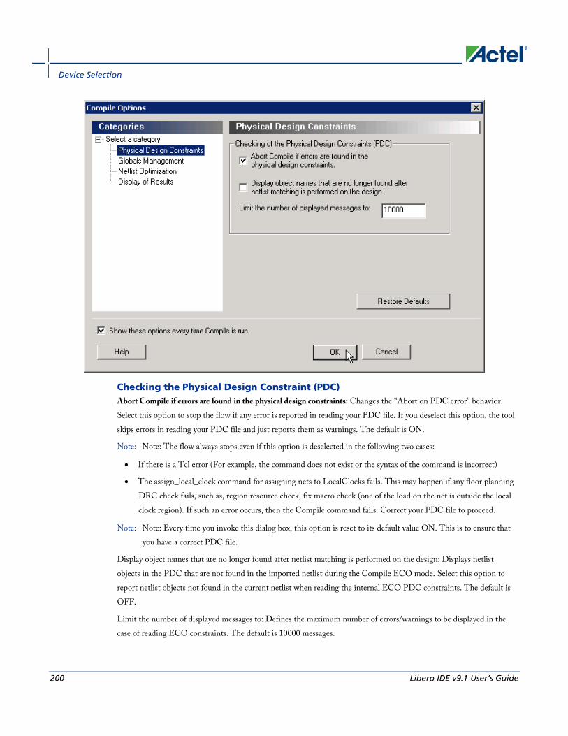
Device Selection
200 Libero IDE v9.1 User’s Guide
Checking the Physical Design Constraint (PDC) Abort Compile if errors are found in the physical design constraints: Changes the “Abort on PDC error” behavior. Select this option to stop the flow if any error is reported in reading your PDC file. If you deselect this option, the tool skips errors in reading your PDC file and just reports them as warnings. The default is ON.
Note: Note: The flow always stops even if this option is deselected in the following two cases:
• If there is a Tcl error (For example, the command does not exist or the syntax of the command is incorrect)
• The assign_local_clock command for assigning nets to LocalClocks fails. This may happen if any floor planning DRC check fails, such as, region resource check, fix macro check (one of the load on the net is outside the local clock region). If such an error occurs, then the Compile command fails. Correct your PDC file to proceed.
Note: Note: Every time you invoke this dialog box, this option is reset to its default value ON. This is to ensure that you have a correct PDC file.
Display object names that are no longer found after netlist matching is performed on the design: Displays netlist objects in the PDC that are not found in the imported netlist during the Compile ECO mode. Select this option to report netlist objects not found in the current netlist when reading the internal ECO PDC constraints. The default is OFF.
Limit the number of displayed messages to: Defines the maximum number of errors/warnings to be displayed in the case of reading ECO constraints. The default is 10000 messages.
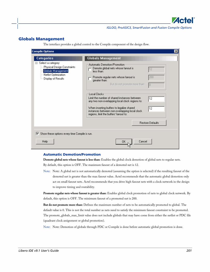
IGLOO, ProASIC3, SmartFusion and Fusion Compile Options
Libero IDE v9.1 User’s Guide 201
Globals Management The interface provides a global control to the Compile component of the design flow.
Automatic Demotion/Promotion Demote global nets whose fanout is less than: Enables the global clock demotion of global nets to regular nets. By default, this option is OFF. The maximum fanout of a demoted net is 12.
Note: Note: A global net is not automatically demoted (assuming the option is selected) if the resulting fanout of the demoted net is greater than the max fanout value. Actel recommends that the automatic global demotion only act on small fanout nets. Actel recommends that you drive high fanout nets with a clock network in the design to improve timing and routability.
Promote regular nets whose fanout is greater than: Enables global clock promotion of nets to global clock network. By default, this option is OFF. The minimum fanout of a promoted net is 200.
But do not promote more than: Defines the maximum number of nets to be automatically promoted to global. The default value is 0. This is not the total number as nets need to satisfy the minimum fanout constraint to be promoted. The promote_globals_max_limit value does not include globals that may have come from either the netlist or PDC file (quadrant clock assignment or global promotion).
Note: Note: Demotion of globals through PDC or Compile is done before automatic global promotion is done.

Device Selection
202 Libero IDE v9.1 User’s Guide
Note: You may exceed the number of globals present in the device if you have nets already assigned to globals or quadrants from the netlist or by using a PDC file. The automatic global promotion adds globals on what already exists in the design.
Local clocks Limit the number of shared instances between any two non-overlapping local clock regions to: Defines the maximum number of shared instances allowed to perform the legalization. It is also for quadrant clocks.
The maximum number of instances allowed to be shared by 2 local clock nets assigned to disjoint regions to perform the legalization (default is 12, range is 0-1000). If the number of shared instances is set to 0, no legalization is performed.
When inserting buffers to legalize shared instances between non-overlapping local clock regions, limit the buffers' fanout to: Defines the maximum fanout value used during buffer insertion for clock legalization. Set the value to 0 to disable this option and prevent legalization (default value is 12, range is 0-1000). If the value is set to 0, no buffer insertion is performed. If the value is set to 1, there will be one buffer inserted per pin.
Note: Note: If you assign quadrant clock to nets using MultiView Navigator, no legalization is performed.
Netlist Optimization This interface allows you to perform netlist optimization.

IGLOO, ProASIC3, SmartFusion and Fusion Compile Options
Libero IDE v9.1 User’s Guide 203
Combining Combine registers into I/O wherever possible: Combines registers at the I/O into I/O-Registers. Select this option for optimization to take effect. By default, this option is OFF.
Buffer/Inverter Management Delete buffers and inverter trees whose fanout is less than: Enables buffer tree deletion on the global signals from the netlist. The buffer and inverter are deleted. By default, this option is OFF. The maximum fanout of a net after buffer tree deletion is 12.
Note: Note: A net does not automatically remove its buffer tree (assuming the option is on) if the resulting fanout of the net (if the buffer tree was removed) is greater than the max fanout value. Actel recomends that the automatic buffer tree deletion should only act on small fanout nets. From a routability and timing point of view, it is not recommended to have high fanout nets not driven by a clock network in the design.
Display of Results This interface lets you generate a Compile report.

Device Selection
204 Libero IDE v9.1 User’s Guide
Compile Report Limit the number of displayed high fanout nets to: Enables flip-flop net sections in the compile report and defines the number of nets to be displayed in the high fanout. The default value is 10.
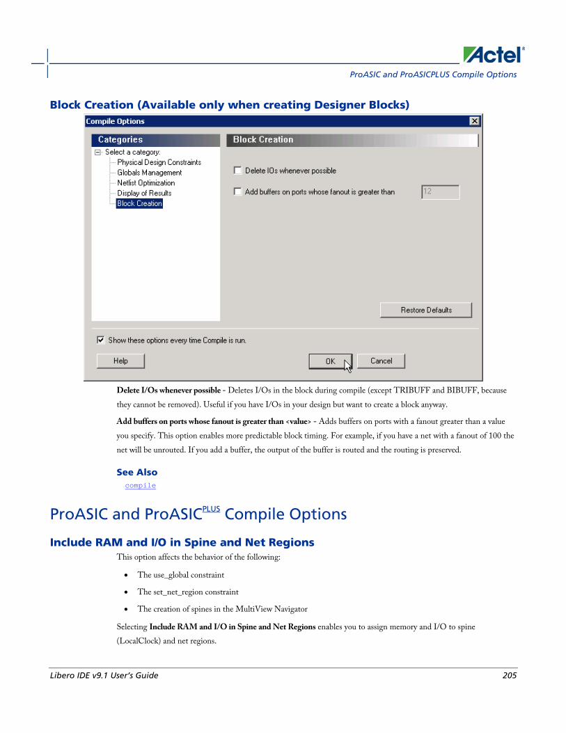
ProASIC and ProASICPLUS Compile Options
Libero IDE v9.1 User’s Guide 205
Block Creation (Available only when creating Designer Blocks)
Delete I/Os whenever possible - Deletes I/Os in the block during compile (except TRIBUFF and BIBUFF, because they cannot be removed). Useful if you have I/Os in your design but want to create a block anyway.
Add buffers on ports whose fanout is greater than <value> - Adds buffers on ports with a fanout greater than a value you specify. This option enables more predictable block timing. For example, if you have a net with a fanout of 100 the net will be unrouted. If you add a buffer, the output of the buffer is routed and the routing is preserved.
See Also compile
ProASIC and ProASICPLUS Compile Options
Include RAM and I/O in Spine and Net Regions This option affects the behavior of the following:
• The use_global constraint
• The set_net_region constraint
• The creation of spines in the MultiView Navigator
Selecting Include RAM and I/O in Spine and Net Regions enables you to assign memory and I/O to spine (LocalClock) and net regions.

Device Selection
206 Libero IDE v9.1 User’s Guide
When this option is selected, Designer applies the use_global and set_net_region constraints to core cells, memory, and I/O. When cleared, Designer applies the use_global and set_net_region constraints to core cells only. For new designs, this box is automatically checked. For designs created with v5.1 or earlier, this option is cleared by default. If you change this default setting, you must recompile your design.
This option also determines whether memory and I/O are included in a LocalClock region that you create with the ChipPlanner tool. If selected, memory and I/O are included. If cleared, they are excluded.
Axcelerator Compile Options The Axcelerator Compile Options dialog box enables you to do the following:
• Set your Block Instantiation options (used for conflict resolution when you instantiate multiple blocks)
• Verify Physical Design Constraints
• Netlist Optimization
• Generate a Compile report in Display of Results
• Set Block Creation options (available only if you are creating a block)

Axcelerator Compile Options
Libero IDE v9.1 User’s Guide 207
Block Instantiation
Designer uses the Block Instantiation options to resolve conflicts between multiple blocks in your design. The default options is to return an error if there is overlapping placement between the blocks and resolve any conflict for nets.
This ensures you are aware that the blocks overlap; you can go back and set the placement to resolve the conflicts and it will Compile.
See Conflict resolution in Designer Blocks for more information.
Physical Design Constraints This interface enables you to verify the Physical Design Constraints (PDC) file.

Device Selection
208 Libero IDE v9.1 User’s Guide
Checking the Physical Design Constraint (PDC) Abort Compile if errors are found in the physical design constraints: Changes the “Abort on PDC error” behavior. Select this option to stop the flow if any error is reported in reading your PDC file. If you deselect this option, the tool skips errors in reading your PDC file and just reports them as warnings. The default is ON.
Note: Note: The flow always stops even if this option is deselected in the following two cases:
• If there is a Tcl error (For example, the command does not exist or the syntax of the command is incorrect)
• The assign_local_clock command for assigning nets to LocalClocks fails. This may happen if any floor planning DRC check fails, such as, region resource check, fix macro check (one of the load on the net is outside the local clock region). If such an error occurs, then the Compile command fails. Correct your PDC file to proceed.
Note: Note: Every time you invoke this dialog box, this option is reset to its default value ON. This is to ensure that you have a valid PDC file.
Display object names that are no longer found after netlist matching is performed on the design: Displays netlist objects in the PDC that are not found in the imported netlist during the Compile ECO mode. Select this option to report netlist objects not found in the current netlist when reading the internal ECO PDC constraints. The default is OFF.
Limit the number of displayed messages to: Defines the maximum number of errors/warnings to be displayed in the case of reading ECO constraints. The default is 10000 messages.
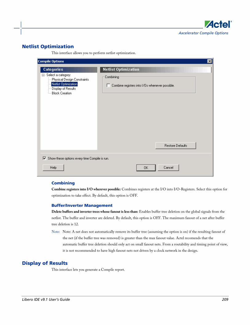
Axcelerator Compile Options
Libero IDE v9.1 User’s Guide 209
Netlist Optimization This interface allows you to perform netlist optimization.
Combining Combine registers into I/O wherever possible: Combines registers at the I/O into I/O-Registers. Select this option for optimization to take effect. By default, this option is OFF.
Buffer/Inverter Management Delete buffers and inverter trees whose fanout is less than: Enables buffer tree deletion on the global signals from the netlist. The buffer and inverter are deleted. By default, this option is OFF. The maximum fanout of a net after buffer tree deletion is 12.
Note: Note: A net does not automatically remove its buffer tree (assuming the option is on) if the resulting fanout of the net (if the buffer tree was removed) is greater than the max fanout value. Actel recomends that the automatic buffer tree deletion should only act on small fanout nets. From a routability and timing point of view, it is not recommended to have high fanout nets not driven by a clock network in the design.
Display of Results This interface lets you generate a Compile report.
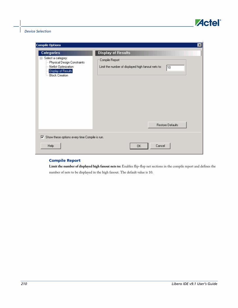
Device Selection
210 Libero IDE v9.1 User’s Guide
Compile Report Limit the number of displayed high fanout nets to: Enables flip-flop net sections in the compile report and defines the number of nets to be displayed in the high fanout. The default value is 10.

MX, SX, SX-A, eX Compile Options
Libero IDE v9.1 User’s Guide 211
Block Creation (available only when creating Designer Blocks)
Delete I/Os whenever possible - Deletes I/Os in the block during compile (except TRIBUFF and BIBUFF, because they cannot be removed). Useful if you have I/O's in your design but want to create a block anyway.
Add buffers on ports whose fanout is greater than <value> - Adds buffers on ports with a fanout greater than a value you specify. This option enables more predictable block timing. For example, if you have a net with a fanout of 100 the net will be unrouted. If you add a buffer, the output of the buffer is routed and the routing is preserved.
See Also compile
MX, SX, SX-A, eX Compile Options
Netlist Pin Properties Overwrite Existing Properties During the Compile process, Designer checks the netlist properties. If the netlist file specifies a pin assignment for a pin that was also assigned in PinEditor session, there is a conflict. How this conflict is resolved is determined by your selection in this check box.
If this option is Off, or cleared, then Designer uses the assignment made in PinEditor, and the assignment in the netlist file for the conflicting pin is ignored. If this option is On, or selected, then Designer uses the assignment in the
Device Selection
212 Libero IDE v9.1 User’s Guide
netlist file for that pin, and the PinEditor assignment is ignored. If you edit pin assignments in PinEditor, this option is automatically set to Off.
Fanout messages Use the control slider in the Messages area to control the warning level. Use the control slider to specify the fanout limit that the Compile step checks against. Setting the control slider to '0' informs the system to use the system defaults. Any non-zero value replaces the system default value for the fanout limit with the user-specified value. Typically, this value range is 1 to 24.
This does not adjust the fanout of the design and it has no effect on the netlist. This only adjusts the warning level by controlling what level of fanout checking you want to be warned about during Compile. Changing this fanout limit option does not invalidate the Compile design state.
MX, SX, SX-A, eX Compile Options
Libero IDE v9.1 User’s Guide 213
Design Constraints
Design constraints are usually either requirements or properties in your design. You use constraints to ensure that your design meets its performance goals and pin assignment requirements.
The Designer software supports both timing and physical constraints. In addition, it supports netlist optimization constraints. You can set constraints by either using Actel's interactive tools or by importing constraint files directly into your design session.
Timing Constraints Timing constraints represent the performance goals for your designs. Designer software uses timing constraints to guide the timing-driven optimization tools in order to meet these goals.
You can set timing constraints either globally or to a specific set of paths in your design.
You can apply timing constraints to:
• Specify the required minimum speed of a clock domain
• Set the input and output port timing information
• Define the maximum delay for a specific path
• Identify paths that are considered false and excluded from the analysis
• Identify paths that require more than one clock cycle to propagate the data
• Provide the external load at a specific port
To get the most effective results from the Designer software, you need to set the timing constraints close to your design goals. Sometimes slightly tightening the timing constraint helps the optimization process to meet the original specifications.
Physical Constraints Designer software enables you to specify the physical constraints to define the size, shape, utilization, and pin/pad placement of a design. You can specify these constraints based on the utilization, aspect ratio, and dimensions of the die. The pin/pad placement depends on the external physical environment of the design, such as the placement of the device on the board.
There are three types of physical constraints:
• I/O assignments
- Set location, attributes, and technologies for I/O ports
- Specify special assignments, such as VREF pins and I/O banks
• Location and region assignments

Design Constraints
214 Libero IDE v9.1 User’s Guide
- Set the location of Core, RAM, and FIFO macros
- Create Regions for I/O and Core macros as well as modify those regions
• Clock assignments
- Assign nets to clocks
- Assign global clock constraints to global, quadrant, and local clock resources
Netlist Optimization Constraints The Designer software enables you to set some advanced design-specific netlist optimizing constraints.
You can apply netlist optimization constraints to:
• Delete or restore a buffer tree
• Manage the fan-outs of the nets
• Manage macro combinations (for example, IO-REG combining)
• Optimize a netlist by removing buffers and/or inverters, propagating constants, and so on
See Also Constraint Support by Family
Constraint Entry Table
Constraint File Format by Family
Designer Naming Conventions

MX, SX, SX-A, eX Compile Options
Libero IDE v9.1 User’s Guide 215
Constraint Entry Use the Constraint Entry table to see which tools and file formats you can use to enter constraints for your device family.
Click the name of a constraint, a constraint entry tool, file format type, editor, or checkmark in the table for more information about that item.
Table 4 · Constraint Entry by Tool and File Format
Constraint SDC GCF PDC PIN DCF ChipPlanner I/O Attribute
Editor
PinEditor SmartTime/ Timer
Compile Options
Timing
Create a clock
X X X
Create a generated clock
X X
Remove clock uncertainty
X X
Set clock latency
X X
Set clock uncertainty
X X
Set disable timing
X X
Set false path
X X X
Set input delay
X X
Set load on output port
X X X X X

Design Constraints
216 Libero IDE v9.1 User’s Guide
Constraint SDC GCF PDC PIN DCF ChipPlanner I/O Attribute
Editor
PinEditor SmartTime/ Timer
Compile Options
Timing
Set maximum delay
X X X
Set minimum delay
X X
Set multicycle path
X X
Set output delay
X X
Physical Placement
-Clocks
Assign Net to Global Clock
X X
Assign Net to Local Clock
X X X
Assign Net to Quadrant Clock
X X
-Regions
Assign Macro to Region
X X

MX, SX, SX-A, eX Compile Options
Libero IDE v9.1 User’s Guide 217
Constraint SDC GCF PDC PIN DCF ChipPlanner I/O Attribute
Editor
PinEditor SmartTime/ Timer
Compile Options
Timing
Assign Net to Region
X X X
Create Region
X X X
Delete Regions
X X
Move region
X X
Unassign macro(s) driven by net
X X
Unassign macro from region
X X
-I/Os
Assign I/O to pin
X X X X X X
Assign I/O Macro to Location
X X X
Configure I/O Bank
X X X
Reset attributes on I/O to
X X X

Design Constraints
218 Libero IDE v9.1 User’s Guide
Constraint SDC GCF PDC PIN DCF ChipPlanner I/O Attribute
Editor
PinEditor SmartTime/ Timer
Compile Options
Timing
default settings
Reset I/O bank to default settings
X X X
Reserve pins
X X X
Unreserve pins
X X X
Unassign I/O macro from location
X X
-Blocks
Move Block
X
Set port block
X X
Set Block Options
X X
-Nets
Assign Net to Global Clock
X X
Assign Net to Local
X X X
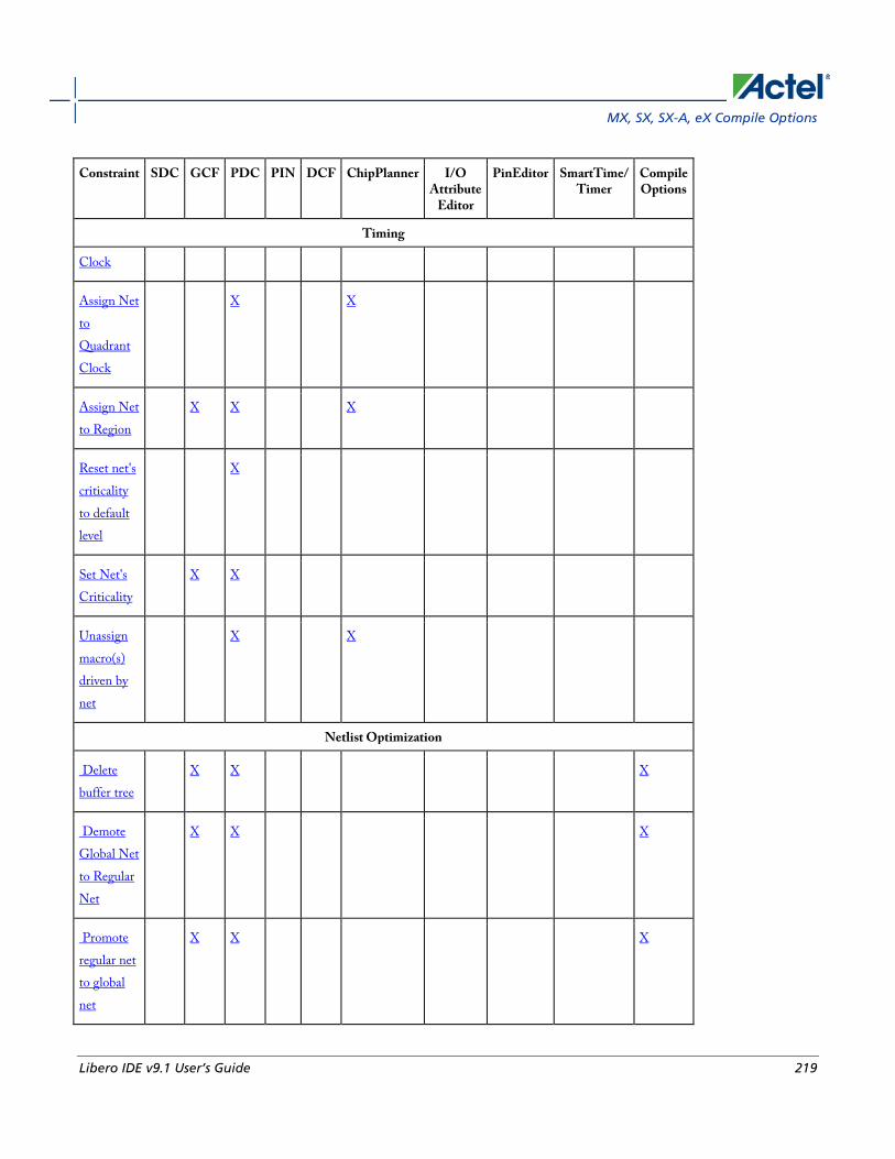
MX, SX, SX-A, eX Compile Options
Libero IDE v9.1 User’s Guide 219
Constraint SDC GCF PDC PIN DCF ChipPlanner I/O Attribute
Editor
PinEditor SmartTime/ Timer
Compile Options
Timing
Clock
Assign Net to Quadrant Clock
X X
Assign Net to Region
X X X
Reset net's criticality to default level
X
Set Net's Criticality
X X
Unassign macro(s) driven by net
X X
Netlist Optimization
Delete buffer tree
X X X
Demote Global Net to Regular Net
X X X
Promote regular net to global net
X X X

Design Constraints
220 Libero IDE v9.1 User’s Guide
Constraint SDC GCF PDC PIN DCF ChipPlanner I/O Attribute
Editor
PinEditor SmartTime/ Timer
Compile Options
Timing
Restore buffer tree
X X
Set preserve
X
See Also Constraint Support by Family
Constraint File Format by Family

MX, SX, SX-A, eX Compile Options
Libero IDE v9.1 User’s Guide 221
Families Supported
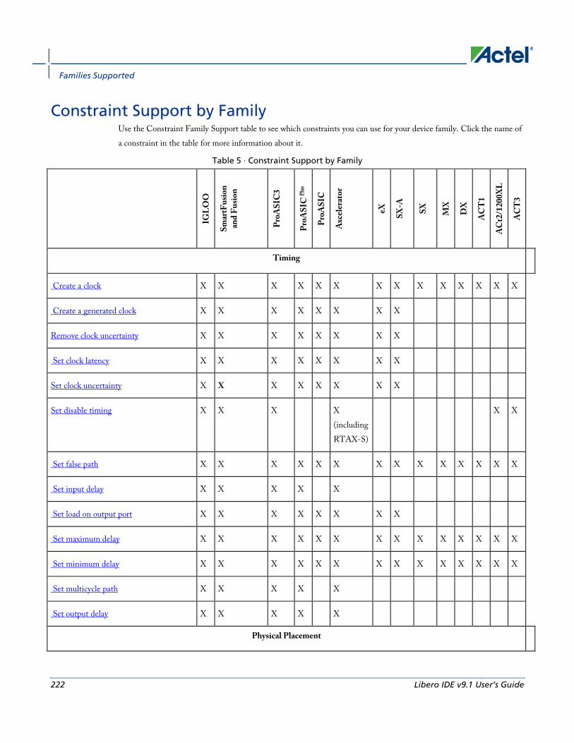
Families Supported
222 Libero IDE v9.1 User’s Guide
Constraint Support by Family Use the Constraint Family Support table to see which constraints you can use for your device family. Click the name of a constraint in the table for more information about it.
Table 5 · Constraint Support by Family
IGLO
O
Smar
tFus
ion
and
Fusio
n
ProA
SIC
3
ProA
SIC
Plus
ProA
SIC
Axc
eler
ator
eX
SX-A
SX
MX
DX
AC
T1
AC
t2/1
200X
L
AC
T3
Timing
Create a clock X X X X X X X X X X X X X X
Create a generated clock X X X X X X X X
Remove clock uncertainty X X X X X X X X
Set clock latency X X X X X X X X
Set clock uncertainty X X X X X X X X
Set disable timing X X X X (including RTAX-S)
X X
Set false path X X X X X X X X X X X X X X
Set input delay X X X X X
Set load on output port X X X X X X X X
Set maximum delay X X X X X X X X X X X X X X
Set minimum delay X X X X X X X X X X X X X X
Set multicycle path X X X X X
Set output delay X X X X X
Physical Placement
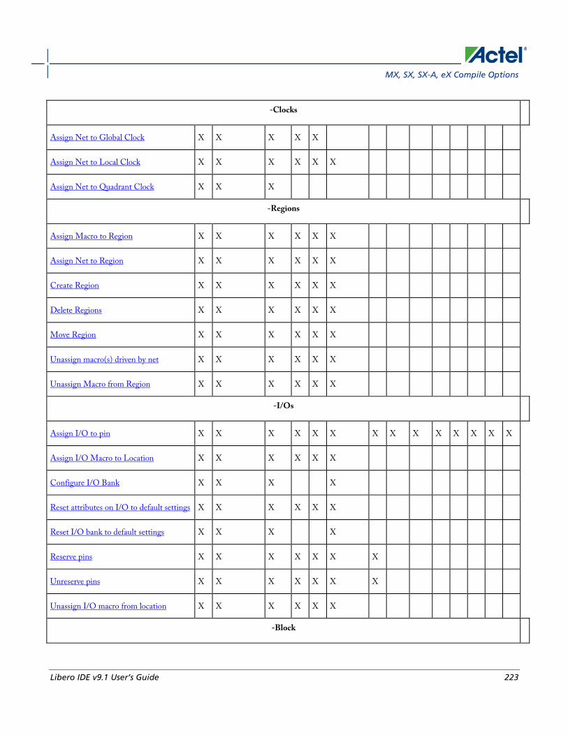
MX, SX, SX-A, eX Compile Options
Libero IDE v9.1 User’s Guide 223
-Clocks
Assign Net to Global Clock X X X X X
Assign Net to Local Clock X X X X X X
Assign Net to Quadrant Clock X X X
-Regions
Assign Macro to Region X X X X X X
Assign Net to Region X X X X X X
Create Region X X X X X X
Delete Regions X X X X X X
Move Region X X X X X X
Unassign macro(s) driven by net X X X X X X
Unassign Macro from Region X X X X X X
-I/Os
Assign I/O to pin X X X X X X X X X X X X X X
Assign I/O Macro to Location X X X X X X
Configure I/O Bank X X X X
Reset attributes on I/O to default settings X X X X X X
Reset I/O bank to default settings X X X X
Reserve pins X X X X X X X
Unreserve pins X X X X X X X
Unassign I/O macro from location X X X X X X
-Block

Families Supported
224 Libero IDE v9.1 User’s Guide
IGLO
O
Smar
tFus
ion
and
Fusio
n
ProA
SIC
3
ProA
SIC
Plus
ProA
SIC
Axc
eler
ator
eX
SX-A
SX
MX
DX
AC
T1
AC
t2/1
200X
L
AC
T3
Timing
Move Block X X X X
Set port block X X X X
Set Block Options X X X X
-Nets
Assign Net to Global Clock X X X X X
Assign Net to Local Clock X X X X X X
Assign Net to Quadrant Clock X X X
Assign Net to Region X X X X X X
Reset net's criticality to default level X
Set Net's Criticality X
Unassign macro(s) driven by net X X X X X
Netlist Optimization
Delete buffer tree X X X
Demote Global Net to Regular Net X X X X X
Promote regular net to global net X X X X X
Restore buffer tree X X X X X
Set preserve X X X X

MX, SX, SX-A, eX Compile Options
Libero IDE v9.1 User’s Guide 225
See Also Constraint Entry Table
Constraint File Format by Family

Families Supported
226 Libero IDE v9.1 User’s Guide
Constraint File Format by Family Use the File Format by Family table to see which file formats apply to each type of constraint and each device family.
Table 6 · Constraint File Format by Family
Family Timing Physical Placement Netlist Optimiization
SDC DCF PDC PIN GCF PDC GCF
IGLOO X X
SmartFusion / Fusion X X X
ProASIC3 X X
ProASIC PLUS X X X
ProASIC X X X
Axcelerator X X X
eX X X X
SX-A X X X
SX X X
MX X X
DX X X
ACT3 X X
ACT2/1200XL X X
ACT1 X X
SDC – Synopsys Design Constraints
PDC – Physical Design Constraints for IGLOO, ProASIC3, SmartFusion, Fusion, and Axcelerator
GCF – Design Constraints Format for ProASICPLUS and ProASIC
DCF – Actel Design Constraints Format
PIN – Pin location constraints

MX, SX, SX-A, eX Compile Options
Libero IDE v9.1 User’s Guide 227
See Also Constraint Support by Family
Constraint Entry Table

Entering Constraints
228 Libero IDE v9.1 User’s Guide
Entering Constraints
You can enter design constraints in the following ways:
• Importing constraint files: You can import GCF, PDC, SDC, DCF, or PIN constraint files. The type of file you use depends on which type of device you are designing.
- GCF (ProASIC and ProASICPLUS families)
- PDC (IGLOO, ProASIC3, SmartFusion, Fusion, and Axcelerator families)
- SDC (IGLOO, ProASIC3, SmartFusion, Fusion, Axcelerator, RTAX-S, eX, and SX-A families)
- DCF (earlier Antifuse families such as eX, SX-A, and SX)
- PIN (only valid for earlier Antifuse families such as eX, SX-A, and SX)
• Using constraint editor tools: Designer's constraint editors are graphical user interface (GUI) tools for creating and modifying physical, logical, and timing constraints. Using these tools enables you to enter constraints without having to understand GCF, PDC, or other file syntax. Which constraint editor you use depends on which type of device you are designing.
For IGLOO, ProASIC3, SmartFusion, Fusion, ProASICPLUS, ProASIC, and Axcelerator, use the tools within the MultiView Navigator:
- ChipPlanner - Sets location and region assignments
- PinEditor in MVN - Sets the pin location constraints
- I/O Attribute Editor - Sets I/O attributes
- SmartTime Constraints EditorSmartTime Constraints Editor - Enables you to view and edit timing constraints
For all other families, you will use the following tools:
- ChipEditor - Sets location and region assignments
- PinEditor (non MVN)- Sets I/O attributes and pin location constraints
- Timer - Sets timing constraints
See Also Constraint Support by Family
Constraint Entry
Constraint File Format by Family
Designer Naming Conventions

IGLOO, ProASIC3, SmartFusion and Fusion Layout Options
Libero IDE v9.1 User’s Guide 229
Running Layout
Use Layout to place and route your design.
To run Layout:
1. Click the Layout button in the Design Flow Window.
2. Layout Options. Select your Layout options and Click OK. Layout options are family specific:
• IGLOO, Fusion, and ProASIC3 Layout Options
• ProASICPLUS and ProASIC Layout Options
• Axcelerator Layout Options
• eX, SX, and SX-A Layout Options
• ACT, MX, and DX Layout Options
IGLOO, ProASIC3, SmartFusion and Fusion Layout Options When running layout, use the Layout Options dialog box to set your layout options.
The I/O Bank Assigner and Global Planner run automatically after you click OK in the Layout Options dialog box. The I/O Bank Assigner automatically assigns technologies to all I/O banks that have not been assigned a technology. The Global Planner automatically assigns global nets to clock conditioning circuit (CCC) locations on the chip in the design.
Note: Note: All I/O technologies assigned to I/O banks by the I/O Bank Assigner in Layout are unlocked.
Timing-Driven Select this option to run Timing-Driven Layout. The primary goal of timing-driven layout is to meet timing constraints, specified by you or generated automatically. Timing-driven Layout typically delivers better performance than Standard layout.
If you do not select Timing-driven layout, Designer runs Standard layout. Standard layout targets efficient usage of the chip resources. Chip performance is not optimized. Timing constraints are not considered by the Layout in standard mode, although a delay report based on delay constraints entered in Timer can still be generated for the design. This is helpful to determine if timing-driven Layout is required.
If your design has multiple scenarios, you can select a scenario from the pull-down list to perform timing driven layout.

Running Layout
230 Libero IDE v9.1 User’s Guide
Power-Driven Select this option to run Power-Driven Layout. The primary goal of power-driven layout is to reduce dynamic power while still maintaining timing constraints.
To get the most out of Power-Driven Layout, it is recommended to:
1. Enter maximum delay, minimum delay, setup, and hold constraints in SmartTime's constraint editor or in SDC.
2. Set false paths on any paths that have a constraint, but do not need one (this will help layout meet the constraints that are needed).
3. Perform Layout with Timing-Driven, Run Place, and Run Route options checked.
4. Resolve worst case setup and maximum delay violations.
5. Generate an SDF back-annotation file.
6. Perform a post layout back-annotated simulation using this SDF file, and export a VCD (Value Change Dump) file that will capture real activities for each net.
7. Import this VCD file in Designer using the Import Auxiliary option from the File menu.
8. Perform Layout with Timing-Driven and Power-Driven checked. Run Place and Route.
9. Verify that your timing constraints are still met with SmartTime.
10. Analyze your power with SmartPower.
In case you do not have simulation vectors for your design, the following alternative flow is recommended:
1. Enter maximum delay, minimum delay, setup, and hold constraints in SmartTime's constraint editor or in SDC.
2. Set false paths on any paths that have a constraint, but do not need one (this will help layout to meet the constraints that are needed).
3. Perform Layout with Timing-Driven, Run Place, and Run Route options checked.
4. Resolve worst case setup and maximum delay violations.
5. Verify that your timing constraints are still met with SmartTime.
6. Open SmartPower and set clock frequencies and toggle rates for the different clocks. Clock frequencies can be imported from your timing constraints. Refer to Initialize Frequencies for more information.
7. Perform Layout with Timing-Driven, and Power-Driven options checked. Run Place and Route.
8. Verify that your timing constraints are still met with SmartTime.
9. Analyze your power with SmartPower
Run Place Select this option to run the placer during Layout. By default, it reflects the current Layout state. If you have not run Layout before, Run Place is selected by default. If your design has already been placed but not routed, this box is cleared by default. You can also select the following incremental placement options.
• Incrementally: Select to use previous placement data as the initial placement for the next place run.

IGLOO, ProASIC3, SmartFusion and Fusion Advanced Layout Options
Libero IDE v9.1 User’s Guide 231
• Lock Existing Placement (fix): Select to preserve previous placement data during the next incremental placement run.
Incremental options apply to the entire design. For more detailed control of the placer behavior (such as, to fix placement of a portion of the design), use the MultiView Navigator tools or set fixed attributes on the placed instances via PDC constraint files.
Run Route Select to run the router during Layout. By default, it reflects the current Layout state. If you have not run Layout before, Run Route is checked. Run Route is also checked if your previous Layout run completed with routing failures. If your design has been routed successfully, this check box is cleared.
• Incrementally: Select to fully route a design when some nets failed to route during a previous run. You can also use it when the incoming netlist has undergone an ECO. (Engineering Change Order). Incremental routing should only be used if a low number of nets fail to route (less than 50 open nets or shorted segments). A high number of failures usually indicates a less than optimal placement (if using manual placement through macros, for example) or a design that is highly connected and does not fit in the device. If a high number of nets fail, relax constraints, remove tight placement constraints, deactivate timing-driven mode, or select a bigger device and rerun Layout. Also, see the Advanced Layout options for your device.
There is no "Fix" option for the router. In incremental mode the router tries to preserve the existing routing; there is no guarantee that it will be preserved. Therefore the timing characteristics of the previously routed portion of the design may change, even if the placement was fixed for that portion of the design. The chance of this is quite small, and the router will print the list of nets that have fixed terminals (i.e. those nets whose every pin's macro has the placement FIX attribute).
Use Multiple Passes Select to run layout multiple times with different seeds. Multiple Pass Layout attempts to improve layout quality by selecting from a greater number of layout results. Click Configure to set your Multiple Pass Configuration.
Click the Advanced button to set Timing-Driven options.
See Also Running Layout
IGLOO, ProASIC3, SmartFusion and Fusion Advanced Layout Options
To set these advanced options during Layout, click Advanced in the Layout dialog box. The Advanced Layout options are only available in timing-driven Layout mode.

Running Layout
232 Libero IDE v9.1 User’s Guide
High Effort Layout Mode This option turns on netlist optimizations to obtain better performance. Layout runtime will increase when this option is selected. You can also combine this option with the Multi-Pass mode to achieve the best possible performance.
In the regular flow the compile step in Designer would modify the netlist to make use of efficient resources on the chip, such as global networks and special macros. When the High Effort Layout option is turned on, the placer could further change the mapping of the logic components, preserving the original functionality of the design. The changed netlist is then used in all post-layout Designer tools including back-annotation.
The names and types of the combinational core logic primitives may change. All other logic cells (such as registers, memory, I/Os or clocks) or combinational logic primitives that are assigned a physical constraint (locked at a location, assigned to a region, or part of a block component), referred in a timing constraint, or have a preserve property, will remain unchanged.
When the Lock Existing Placement option is also turned on, the placer runs in regular effort mode.
Note: Note: If you change the High Effort Setting you must re-run the placer and router to complete Layout.
Sequential Optimization This option turns on optimization of sequential cells in the High Effort Layout mode. This typically enables register retiming without disturbing timing latency. The names of registers may change unless they are assigned a physical constraint (locked at a location, assigned to a region, or part of a block component), referred in a timing constraint, or have a preserve property. Other restrictions may also apply.
Router
Repair Minimum Delay Violations With this option selected, layout will perform an additional route that will attempt to repair paths that have minimum delay and hold time violations. This is done by increasing the length of routing paths and inserting routing buffers to add delay to paths. Since placement will remain unchanged and no additional tiles or modules will be inserted, the amount of delay inserted is limited. As a result, this function is best suited to repair paths with small (0 to 3 ns) hold and minimum delay violations. Paths with large violations will likely improve, but for a complete repair of these paths, manual placement or source code modification may be necessary. Every effort will be made to avoid creating max-delay timing violations on worst case paths.
To get the most out of repair minimum delay violations, it is recommended to:
1. Enter max-delay, min-delay, setup and hold constraints in SmartTime's constraint editor or in SDC.
2. Set false paths on any paths that have a constraint, but do not need one (this will help layout to meet the constraints that are needed).
3. Perform Layout with Timing Driven, Run Place, Run Route and optionally Run incrementally enabled.
4. Resolve worst case setup and max-delay violations before running minimum delay violations repair.
ProASICPLUS and ProASIC Layout Options
Libero IDE v9.1 User’s Guide 233
5. After worst case max-delay timing is resolved, evaluate timing in SmartTime’s Timing Analyzer in minimum delay analysis mode to check for hold time and minimum delay violations.
6. Run repair minimum delay violations with incremental route enabled. The repair minimum delay violations tool will attempt to fix all hold time and minimum delay violations by lengthening routing delay paths and inserting routing buffers. As delay is added to paths, worst case max-delay timing is verified to avoid creating new max-delay timing violations. Designer will report the worst minimum slack and the number of violating paths in the log window. In some cases, additional improvement can occur by running repair minimum delay violations multiple times with Run Incrementally enabled.
7. Perform both maximum and minimum delay timing analysis to check the timing. Manual placement or source code modification may be necessary to repair all minimum delay violations.
8. After making placement or source code changes, run incremental route and repair minimum delay violations, and then analyze timing again.
Additional Factors Runtime may vary greatly with the number of paths that need repair, the number of nets in those paths, and the resources available for the tool to insert delay. Over-constraining paths will increase runtime, but will not likely improve results .
The tool will only work on paths that have min delay and hold time constraints. However, other paths that share common nets to the constrained paths may be inadvertently affected.
It is recommended to run minimum delay violations repair with incremental route. This will ensure that paths which do not have minimum delay violations are preserved.
Repair will be performed on:
• Register to register paths where both registers are on the same global or non-global clock
• Register to register paths where the registers are on different clock networks and a minimum delay constraint exists
• Input to register, register to output, clock to out, input to output paths with minimum delay or hold constraint.
You may select programmable input delays to increase delay on input to register paths for devices that support the feature.
Restore Defaults Click Restore Defaults to run the factory default settings for Advanced options.
ProASICPLUS and ProASIC Layout Options When running layout, use the Layout Options dialog box to set your layout options.

Running Layout
234 Libero IDE v9.1 User’s Guide
Timing-Driven Select this option to run Timing-Driven Layout. The primary goal of timing-driven layout is to meet timing constraints, specified by you or generated automatically. Timing-driven Layout typically delivers better performance than Standard layout.
If you do not select Timing-driven layout, Designer runs Standard layout. Standard layout targets efficient usage of the chip resources. Chip performance is not optimized. Timing constraints are not considered by the Layout in standard mode, although a delay report based on delay constraints entered in Timer can still be generated for the design. This is helpful to determine if timing-driven Layout is required.
Run Place Select this option to run the placer during Layout. By default, it reflects the current Layout state. If you have not run Layout before, Run Place is selected by default. If your design has already been placed but not routed, this box is cleared by default. You can also select the following incremental placement options.
• Incrementally: Select to use previous placement data as the initial placement for the next place run.
• Lock Existing Placement (fix): Select to preserve previous placement data during the next incremental placement run.
Incremental options apply to the entire design. For more detailed control of the placer behavior (such as, to fix placement of a portion of the design), use the MultiView Navigator tools or set fixed attributes on the placed instances via GCF constraint files.
Run Route Select to run the router during Layout. By default, it reflects the current Layout state. If you have not run Layout before, Run Route is checked. Run Route is also checked if your previous Layout run completed with routing failures. If your design has been routed successfully, this check box is cleared.
• Incrementally: Select to fully route a design when some nets failed to route during a previous run. You can also use it when the incoming netlist has undergone an ECO. (Engineering Change Order). Incremental routing should only be used if a low number of nets fail to route (less than 50 open nets or shorted segments). A high number of failures usually indicates a less than optimal placement (if using manual placement through macros, for example) or a design that is highly connected and does not fit in the device. If a high number of nets fail, relax constraints, remove tight placement constraints, deactivate timing-driven mode, or select a bigger device and rerun Layout. Also, see the Advanced Layout options for your device.
There is no "Fix" option for the router. In incremental mode the router tries to preserve the existing routing; there is no guarantee that it will be preserved. Therefore the timing characteristics of the previously routed portion of the design may change, even if the placement was fixed for that portion of the design.

ProASICPLUS and ProASIC Advanced Layout Options
Libero IDE v9.1 User’s Guide 235
Use Multiple Passes Select to run layout multiple times with different seeds. Multiple Pass Layout attempts to improve layout quality by selecting from a greater number of layout results. Click Configure to set your Multiple Pass Configuration.
Click the Advanced button to set Timing-Driven options.
See Also Running Layout
ProASICPLUS and ProASIC Advanced Layout Options To set these advanced options during Layout, click Advanced in the Layout dialog box.
Layout Timing Weight Setting this option to values within a recommended range of 1-4 changes the weight of the timing objective function, thus influencing the results of timing-driven place-and-route in favor of either routability or performance.
Value 4 (default) puts maximum emphasis on the performance; value 1 shifts priority to routability, but still evaluates timing goals during layout.
In general, the performance of a non-congested design increases with a higher timing weight setting. In highly congested designs the performance improves with lower timing weight settings because of better routability. Use intermediate values to balance the performance-routability tradeoff for your design.
For designs that are very congested, you may want to put even more emphasis to the routability than level 1 provides. In this case try running standard-mode placer, followed by the timing-driven router. If this is insufficient, run both place-and-route in standard mode.
Note: Note: If you change the Timing Weight you must re-run the placer to complete routing. Changing the Timing Weight has no effect if you do not re-run the placer.
Restore Defaults Click Restore Defaults to run the factory default settings for advanced options.
Axcelerator Layout Options When running Layout, use the Layout Options dialog box to set your Layout options.
The I/O Bank Assigner runs automatically after you click OK in the Layout Options dialog box. The I/O Bank Assigner automatically assigns technologies to all I/O banks that have not been assigned a technology.
Timing-Driven Select this option to run Timing-Driven Layout. The primary goal of timing-Driven layout is to meet timing constraints, with a secondary goal of producing high performance for the rest of the design. Timing-Driven Layout delivers performance that is superior to Standard Layout; Timing-Driven Layout is selected by default.
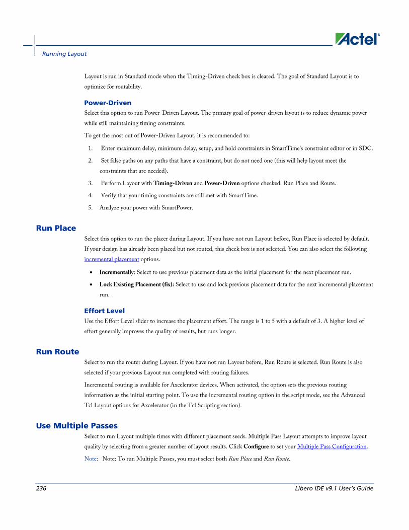
Running Layout
236 Libero IDE v9.1 User’s Guide
Layout is run in Standard mode when the Timing-Driven check box is cleared. The goal of Standard Layout is to optimize for routability.
Power-Driven Select this option to run Power-Driven Layout. The primary goal of power-driven layout is to reduce dynamic power while still maintaining timing constraints.
To get the most out of Power-Driven Layout, it is recommended to:
1. Enter maximum delay, minimum delay, setup, and hold constraints in SmartTime's constraint editor or in SDC.
2. Set false paths on any paths that have a constraint, but do not need one (this will help layout meet the constraints that are needed).
3. Perform Layout with Timing-Driven and Power-Driven options checked. Run Place and Route.
4. Verify that your timing constraints are still met with SmartTime.
5. Analyze your power with SmartPower.
Run Place Select this option to run the placer during Layout. If you have not run Layout before, Run Place is selected by default. If your design has already been placed but not routed, this check box is not selected. You can also select the following incremental placement options.
• Incrementally: Select to use previous placement data as the initial placement for the next placement run.
• Lock Existing Placement (fix): Select to use and lock previous placement data for the next incremental placement run.
Effort Level Use the Effort Level slider to increase the placement effort. The range is 1 to 5 with a default of 3. A higher level of effort generally improves the quality of results, but runs longer.
Run Route Select to run the router during Layout. If you have not run Layout before, Run Route is selected. Run Route is also selected if your previous Layout run completed with routing failures.
Incremental routing is available for Axcelerator devices. When activated, the option sets the previous routing information as the initial starting point. To use the incremental routing option in the script mode, see the Advanced Tcl Layout options for Axcelerator (in the Tcl Scripting section).
Use Multiple Passes Select to run Layout multiple times with different placement seeds. Multiple Pass Layout attempts to improve layout quality by selecting from a greater number of layout results. Click Configure to set your Multiple Pass Configuration.
Note: Note: To run Multiple Passes, you must select both Run Place and Run Route.

Axcelerator Advanced Layout Options
Libero IDE v9.1 User’s Guide 237
Axcelerator Advanced Layout Options To set these advanced options during Layout, click Advanced in the Layout dialog box.
Router
Repair Minimum Delay Violations With this option selected, layout will perform an additional route that will attempt to repair paths that have minimum delay and hold time violations. This is done by increasing the length of routing paths and inserting routing buffers to add delay to paths. Since placement will remain unchanged and no additional tiles or modules will be inserted, the amount of delay inserted is limited. As a result, this function is best suited to repair paths with small (0 to 3 ns) hold and minimum delay violations. Paths with large violations will likely improve, but for a complete repair of these paths, manual placement or source code modification may be necessary. Every effort will be made to avoid creating max-delay timing violations on worst case paths.
To get the most out of repair minimum delay violations, it is recommended to:
1. Enter max-delay, min-delay, setup and hold constraints in SmartTime's constraint editor or in SDC.
2. Set false paths on any paths that have a constraint, but do not need one (this will help layout to meet the constraints that are needed).
3. Perform Layout with Timing Driven, Run Place, Run Route and/or Run incrementally enabled.
4. Resolve worst case setup and max-delay violations before running minimum delay violations repair.
5. After worst case max-delay timing is resolved, evaluate timing in SmartTime’s Timing Analyzer in minimum delay analysis mode to check for hold time and minimum delay violations.
6. Run repair minimum delay violations with incremental route enabled. The repair minimum delay violations tool will attempt to fix all hold time and minimum delay violations by lengthening routing delay paths and inserting routing buffers. As delay is added to paths, worst case max-delay timing is verified to avoid creating new max-delay timing violations. Designer will report the worst minimum slack and the number of violating paths in the log window. In some cases, additional improvement can occur by running repair minimum delay violations multiple times with Run Incrementally enabled.
7. Perform both maximum and minimum delay timing analysis to check the timing. Manual placement or source code modification may be necessary to repair all minimum delay violations.
8. After making placement or source code changes, run incremental route and repair minimum delay violations, and then analyze timing again.
Note: Note: Runtime may vary greatly with the number of paths that need repair, the number of nets in those paths, and the resources available for the tool to insert delay. Over-constraining paths will increase runtime, but will not likely improve results.
The tool will only work on paths that have min delay and hold time constraints. However, other paths that share common nets to the constrained paths may be inadvertently affected.

Running Layout
238 Libero IDE v9.1 User’s Guide
Actel recommends that you run minimum delay violations repair with incremental route. This will ensure that paths which do not have minimum delay violations are preserved.
Repair will be performed on:
• Register to register paths where both registers are on the same global or non-global clock
• Register to register paths where the registers are on different clock networks and a minimum delay constraint exists
• Input to register, register to output, clock to out, input to output paths with minimum delay or hold constraint.
You may select programmable input delays to increase delay on input to register paths for devices that support the feature.
Restore Default Click Restore Defaults to run the factory default settings for Advanced options.
eX, SX, SX-A Layout Options When running layout, use the Layout dialog box to set your layout options.
Timing-Driven Select to run Timing-Driven Layout. The primary goal of Timing-Driven layout is to meet timing constraints, while still producing high performance for the rest of the design. Timing-Driven Layout is more precise and typically results in higher performance. This option is available only when timing constraints have been defined.
When not checked, standard layout runs. Standard layout maximizes the average performance for all paths. Each part of a design is treated equally for performance optimization. Standard layout uses net weighting (or criticality) to influence the results. Delay constraints that have been set for a design during place-and-route are not considered, however a delay report based on delay constraints entered in Timer can still be generated for the design. This is helpful to determine if Timing-Driven Layout is required.
Place Incrementally Select to use previous placement data as the initial placement for the next place run.
• Lock Existing Placement: Select to preserve previous placement data during the next incremental placement run.
Use Multiple Passes (eX and SX-A only) Select to run layout multiple times with different seeds. Multiple Pass Layout attempts to improve layout quality by selecting from a greater number of layout results. Click Configure to set your Multiple Pass Configuration.
Click the Advanced button to set Extended Run and Timing-Driven options.

eX, SX, and SX-A Advanced Layout Options
Libero IDE v9.1 User’s Guide 239
eX, SX, and SX-A Advanced Layout Options To set these advanced options during Layout, click the Advanced button in the Layout dialog box.
Extended Run Select this to run a greater number of iterations during optimization within a single layout pass. An extended run layout can take up to five times as long as a normal layout.
Effort Level This setting specifies the duration of the timing-driven phase of optimization during timing-driven Layout. Its value specifies the duration of this phase as a percentage of the default duration. This option is available only when timing constraints have been defined
The default value is 100 and the selectable range is 25 - 500. Reducing the effort level also reduces the run time of timing-driven place-and-route (TDPR). With an effort level of 25, TDPR is almost four times faster. With fewer iterations, however, performance may suffer. Routability may or may not be affected. With an effort level of 200, TDPR is almost two times slower. This variable does not have much effect on timing.
Timing Weight Setting this option to values within a recommended range of 10-150 changes the weight of the timing objective function, thus influencing the results of timing-driven place-and-route in favor of either routability or performance. This option is available only when timing constraints have been defined
The timing weight value specifies this weight as a percentage of the default weight (i.e. a value of 100 has no effect). If you use a value less than 100, more emphasis is placed on routability and less on performance. Such a setting would be appropriate for a design that fails to route with TDPR. In case more emphasis on performance is desired, set this variable to a value higher than 100. In this case, routing failure is more likely. A very high timing value weight could also distort the optimization process and degrade performance. A value greater than 150 is not recommended.
Restore Defaults Click Restore Defaults to run the factory default settings for advanced options.
ACT, MX, and DX Layout Options
Timing-Driven Select this option to run Timing-Driven Layout. The primary goal of timing-driven layout is to meet timing constraints, with a secondary goal of producing high performance for the rest of the design. Timing-Driven Layout is more precise and typically results in higher performance. This option is available only when timing constraints have been defined.

Running Layout
240 Libero IDE v9.1 User’s Guide
When not checked, Designer runs standard layout. Standard layout maximizes the average performance for all paths. Each part of a design is treated equally for performance optimization. Standard layout uses net weighting (or criticality) to influence the results. Delay constraints that have been set for a design during place-and-route are not considered, however a delay report based on delay constraints entered in Timer can still be generated for the design. This is helpful to determine if Timing-Driven Layout is required.
Place Incrementally Select to use previous placement data as the initial placement for the next place run.
• Lock Existing Placement: Select to preserve previous placement data during the next incremental placement run.
Click Advanced to set Extended Run options.
ACT, MX, and DX Advanced Layout Options To set these advanced options during Layout, click the Advanced button in the Layout dialog box.
Extended Run Select this to run a greater number of iterations during optimization. An extended run layout can take up to five times as long as a normal layout.
Restore Default Click Restore Defaults to run the factory default settings for advanced options.
See Also Running Layout
ACT, MX, and DX Layout options
Incremental Placement In either standard or timing-driven mode, use incremental placement to preserve the timing of a design after a successful place-and-route, even if you change part of the netlist. Incremental placement has no effect the first time you run layout. During design iteration, incremental placement attempts to preserve the placement information for any unchanged macros in a modified netlist.
As a result, the timing relationships for unchanged macros approximate their initial values, decreasing the execution time to perform Layout. By forcing Designer to retain the placement information for a portion of the design, some flexibility for optimal design layout may be lost. Therefore, do not use incremental placement to place your design in pieces. You should only use it if you have successfully run Layout and you have minor changes to your design.
Incremental placement requires prior completion of place. Do not use incremental placement if the previous Layout failed to meet performance goals.

Running Multiple Pass Layout
Libero IDE v9.1 User’s Guide 241
Locking Existing Placement (Fix) When the Lock Existing Placement option is selected in the Layout dialog box, all unchanged macros are treated as locked (fixed) placements during an incremental placement. This is the strongest level of control, but it may be too restrictive for the new placement to successfully complete. The default ON setting treats unchanged macro locations as placement hints, but alters their locations as needed to successfully complete placement. Refer to ChipEditorfor details on locking macros.
ProASIC and ProASICPLUS Placement Constraint File (GCF) For ProASIC and ProASICPLUS designs, you can export a GCF constraint file to get all of the constraint information. From the File menu, choose Export > Constraint Files, type a file name and click Save, and then select All GCF constraints in the Export GCF File dialog box. Blocks with locked placement constraints generate locked placement constraints, while the others generate initial placement constraints. You can edit a GCF file to remove existing constraints or add new constraints. You must then import the modified GCF file as well as the netlist back into Designer. See Importing Source Files for more information about importing files.
Running Multiple Pass Layout Multiple Pass Layout attempts to improve layout quality by selecting from a greater number of Layout results. This is done by running individual place and route multiple times with varying placement seeds and measuring the best results with specified criteria.
Note: Note:
• Before running Multiple Pass Layout, you need to save your design.
• Multiple Pass Layout is supported in the following families: IGLOO, Fusion, ProASIC3, Axcelerator, ProASICPLUS, ProASIC, SX-A, and eX.
• Multiple Pass Layout saves your design file with the pass that has the best layout results. If you want to preserve your existing design state, you should save your design file with a different name before proceeding. To do this, from the File menu, select Save As.
• Four types of reports (timing, maximum delay timing violations, minimum delay timing violations, and power) for each pass will be written out to the working directory to assist you in later analysis:
• <adbFileName>_timing_r<runNum>_s<seedIndex>.rpt
• <adbFileName>_timing_violations_r<runNum>_s<seedIndex>.rpt
• <adbFileName>_timing_violations_min_r<runNum>_s<seedIndex>.rpt
• <adbFileName>_power_r<runNum>_s<seedIndex>.rpt
• <adbFileName>_iteration_summary.rpt provides additional details about the saved files
To configure your multiple pass options:
1. When running Layout, select Use Multiple Passes in the Layout Options dialog box.

Running Layout
242 Libero IDE v9.1 User’s Guide
2. Click Configure. The Multi-Pass Configuration dialog box appears.
3. Set the options and click OK.
Number ofpasses: Set the number of passes (iterations) using the slider. 1 is the minimum and 25 is the maximum. The recommended number of passes is 5.
Start at seed index: Set the specific index into the array of random seeds which is to be the starting point for the passes.
Measurement: Select the measurement criteria you want to compare layout results against.
• Slowest clock: Select to use the slowest clock frequency in the design in a given pass as the performance reference for the layout pass.
• Specific clock: Select to use a specific clock frequency as the performance reference for all layout passes.
• Timing violations: Select to use the pass that best meets the slack or timing-violations constraints. Note: You must enter your own timing constraints through the SmartTime or SDC.
• Maximum delay: Select to examine timing violations (slacks) obtained from maximum delay analysis.
• Minimum delay: Select to examine timing violations (slacks) obtained from minimum delay analysis.
• Select by: Worst Slack or Total Negative Slack to specify the slack criteria.
• When Worst Slack is selected, the most amount of negative slack (or least amount of positive slack if all constraints are met) for each pass is identified, and then the largest value out of all passes determines the best pass.
• When Total Negative Slack is selected, the sum of negative slacks from the first 100 paths for each pass is identified, and then the largest value out of all the passes determines the best pass. If no negative slacks exist for a pass, then the worst slack is used to evaluate that pass.
• Stop on first path without violations: Select to stop performing remaining passes if all timing constraints have been met (when there are no negative slacks reported in the timing violations report).
• Total power: Select to determine the best pass to be the one that has the lowest total power (static + dynamic) out of all layout passes.
Save design file for each pass: Select to save the design *.adb file for each pass. By default, only the best result is saved to your design. With this option, every pass stores its design file as <adbFileName>_r<runNum>_s<seedIndex>.adb. The "best"-pass design will also be written back to the original *.adb file. Saving all results does take more disk space, but allows you to analyze the result of each pass later in more detail. <adbFileName>_iteration_summary.rpt provides additional details about the saved files.
Iteration Summary Report The file <adbFileName>_iteration_summary.rpt records a summary of how the multiple pass run was invoked either through the GUI or extended_run_shell Tcl script, with arguments for repeating each run. Each new run appears with its own header in the Iteration Summary Report with fields RUN_NUMBER and INVOKED AS , followed by a

Analyzing timing in your design
Libero IDE v9.1 User’s Guide 243
table containing Seed Index, corresponding Seed value, Comparison data, Report Analyzed, and Saved Design information.
Example The first header displays information about the first run invoked from the command line (extended_run_shell). The second run was invoked from the Designer GUI (extended_run_gui).
Figure 70 · Iteration Summary Report
See Also Running Layout
extended_run_shell
extended_run_gui
Analyzing timing in your design You can perform timing analysis using the SmartTime or Timer tool.
The following table lists the timing tool you can use for your device family.
Family SmartTime Timer
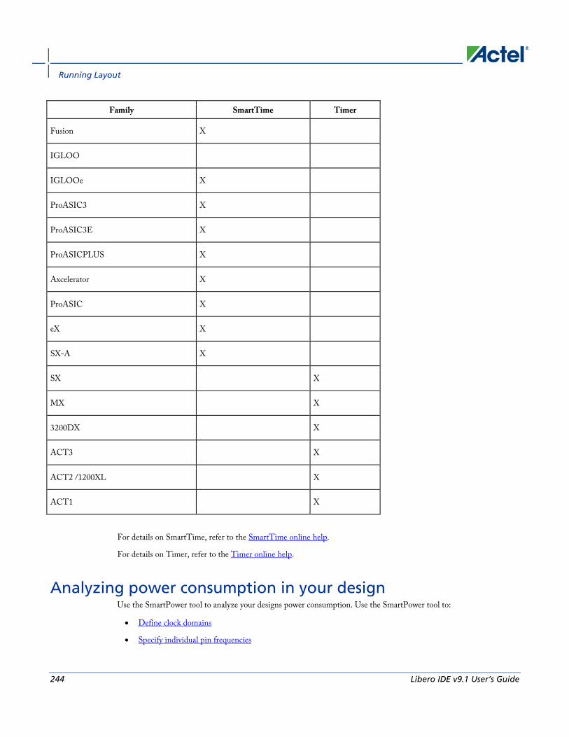
Running Layout
244 Libero IDE v9.1 User’s Guide
Family SmartTime Timer
Fusion X
IGLOO
IGLOOe X
ProASIC3 X
ProASIC3E X
ProASICPLUS X
Axcelerator X
ProASIC X
eX X
SX-A X
SX X
MX X
3200DX X
ACT3 X
ACT2 /1200XL X
ACT1 X
For details on SmartTime, refer to the SmartTime online help.
For details on Timer, refer to the Timer online help.
Analyzing power consumption in your design Use the SmartPower tool to analyze your designs power consumption. Use the SmartPower tool to:
• Define clock domains
• Specify individual pin frequencies

Viewing your netlist
Libero IDE v9.1 User’s Guide 245
• View detailed hierarchical analysis of your design
• View global power consumption at the design level
If you wish, you may also view the equations that SmartPower uses to calculate your power consumption.
Viewing your netlist The NetlistViewer tool displays the contents of the design as a schematic, making it easier for you to debug your design. With NetlistViewer, you can view nets, ports, and instances in the schematic view. You can also isolate specific sections of your netlist to simplify your analysis and cross probe with other tools.
There are two versions of the NetlistViewer tool: NetlistViewer in MultiView Navigator (MVN) and NetlistViewer (non-MVN). Which version you use depends on which family you are designing for.
• NetlistViewer in MultiView Navigator supports IGLOO, Fusion, ProASIC3, ProASIC PLUS, ProASIC, Axcelerator, eX, and SX-A families.
• NetlistViewer (non-MVN) supports MX, DX, ACT3, ACT2, and ACT1 families.
Used with PinEditor in MultiView Navigator, ChipPlanner, or SmartTime, NetlistViewer in MultiView Navigator assists you in meeting area and timing goals by helping you with critical path identification. NetlistViewer (non-MVN) can also be used alone or with PinEditor Standalone, ChipEditor, or Timer.
When you open your design (.adb) file, Designer will automatically present you with the appropriate tools in the Design Flow window. You must compile your design before you can open it in NetlistViewer.
See Also Overview- MultiView Navigator
About NetlistViewer in MultiView Navigator
About NetlistViewer (non-MVN)
Back-Annotation The back-annotation functions are used to extract timing delays from your post layout data. These extracted delays are put into a file to be used by your CAE package’s timing simulator. If you wish to perform pre-layout back-annotation, select Export and Timing Files from the File menu.
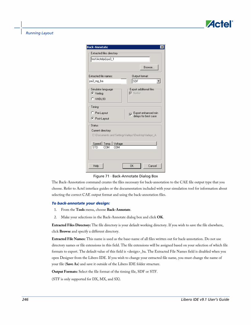
Running Layout
246 Libero IDE v9.1 User’s Guide
Figure 71 · Back-Annotate Dialog Box
The Back-Annotation command creates the files necessary for back-annotation to the CAE file output type that you choose. Refer to Actel interface guides or the documentation included with your simulation tool for information about selecting the correct CAE output format and using the back-annotation files.
To back-annotate your design:
1. From the Tools menu, choose Back-Annotate.
2. Make your selections in the Back-Annotate dialog box and click OK.
Extracted Files Directory: The file directory is your default working directory. If you wish to save the file elsewhere, click Browse and specify a different directory.
Extracted File Names: This name is used as the base-name of all files written out for back-annotation. Do not use directory names or file extensions in this field. The file extensions will be assigned based on your selection of which file formats to export. The default value of this field is <design>_ba. The Extracted File Names field is disabled when you open Designer from the Libero IDE. If you wish to change your extracted file name, you must change the name of your file (Save As) and save it outside of the Libero IDE folder structure.
Output Formats: Select the file format of the timing file, SDF or STF.
(STF is only supported for DX, MX, and SX).
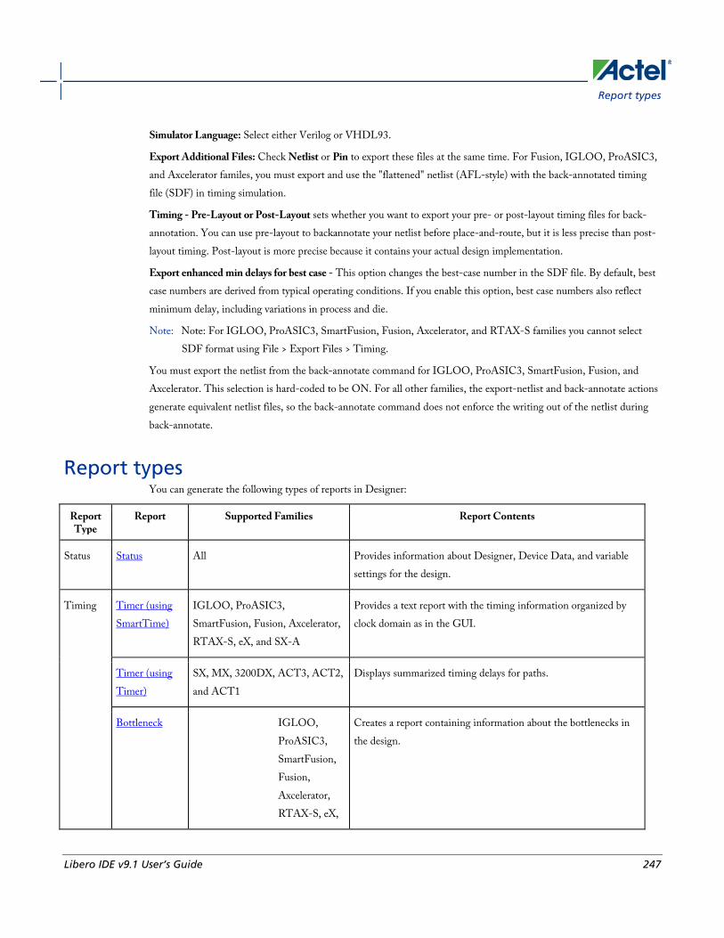
Report types
Libero IDE v9.1 User’s Guide 247
Simulator Language: Select either Verilog or VHDL93.
Export Additional Files: Check Netlist or Pin to export these files at the same time. For Fusion, IGLOO, ProASIC3, and Axcelerator familes, you must export and use the "flattened" netlist (AFL-style) with the back-annotated timing file (SDF) in timing simulation.
Timing - Pre-Layout or Post-Layout sets whether you want to export your pre- or post-layout timing files for back-annotation. You can use pre-layout to backannotate your netlist before place-and-route, but it is less precise than post-layout timing. Post-layout is more precise because it contains your actual design implementation.
Export enhanced min delays for best case - This option changes the best-case number in the SDF file. By default, best case numbers are derived from typical operating conditions. If you enable this option, best case numbers also reflect minimum delay, including variations in process and die.
Note: Note: For IGLOO, ProASIC3, SmartFusion, Fusion, Axcelerator, and RTAX-S families you cannot select SDF format using File > Export Files > Timing.
You must export the netlist from the back-annotate command for IGLOO, ProASIC3, SmartFusion, Fusion, and Axcelerator. This selection is hard-coded to be ON. For all other families, the export-netlist and back-annotate actions generate equivalent netlist files, so the back-annotate command does not enforce the writing out of the netlist during back-annotate.
Report types You can generate the following types of reports in Designer:
Report Type
Report Supported Families Report Contents
Status Status All Provides information about Designer, Device Data, and variable settings for the design.
Timing Timer (using SmartTime)
IGLOO, ProASIC3, SmartFusion, Fusion, Axcelerator, RTAX-S, eX, and SX-A
Provides a text report with the timing information organized by clock domain as in the GUI.
Timer (using Timer)
SX, MX, 3200DX, ACT3, ACT2, and ACT1
Displays summarized timing delays for paths.
Bottleneck IGLOO, ProASIC3, SmartFusion, Fusion, Axcelerator, RTAX-S, eX,
Creates a report containing information about the bottlenecks in the design.

Running Layout
248 Libero IDE v9.1 User’s Guide
Report Type
Report Supported Families Report Contents
and SX-A
Constraints Coverage
IGLOO, ProASIC3, SmartFusion, Fusion, Axcelerator, RTAX-S, eX, and SX-A
Creates a report containing information about the constraints in the design.
Datasheet IGLOO, ProASIC3, SmartFusion, Fusion, Axcelerator, RTAX-S, eX, and SX-A
Creates a report containing information about the external characteristics of the design.
Timing Violations (using SmartTime)
IGLOO, ProASIC3, SmartFusion, Fusion, Axcelerator, RTAX-S, eX, and SX-A
Provides a flat slack report centered around constraint violations.
Combinational Loops
IGLOO, ProASIC3, SmartFusion, Fusion, Axcelerator, RTAX-S, eX, and SX-A
This report displays all loops found during initialization and reports pins associated with the loop(s), and the location where the loop is broken.
Resources Pin All Creates a text list of the I/O signal locations on a device. You can generate a pin report sorted by I/O signal names or by package number.
Flip Flop All Creates a report that lists the number and type of flip-flops (sequential or CC, which are flip-flops made of 2 combinatorial macros) used in a design. The flip-flop report can be of two types: Summary or Extended. Both types of reports include the Flip-Flop type, sequential (Seq)

Report types
Libero IDE v9.1 User’s Guide 249
Report Type
Report Supported Families Report Contents
or combinatorial (CC), the Library name, and the Total number of Seq and CC Flip-Flops in the design. The Summary Report also includes the Number of instances of each unique type. The Extended Report provides the Macro name. All Reports are output to an editable window for viewing, modifying, saving, and printing.
IOBank IO Bank IGLOO, ProASIC3, SmartFusion, Fusion, and Axcelerator
Provides information on the I/O functionality, I/O technologies, I/O banks and I/O voltages.
Power Power IGLOO, ProASIC3, SmartFusion, Fusion, ProASICPLUS, ProASIC, and Axcelerator
Enables you to quickly determine if any power consumption problems exist in your design. The power report lists the following information: - Global device information and SmartPower Preferences selection information - Design level static power summary - Dynamic power summary - Hierarchical detailed power report (including gates, blocks, and nets), with a block by block, gate by gate, and net by net power summary SmartPower results.
Power Cycle Accurate
IGLOO, ProASIC3, SmartFusion, Fusion, ProASICPLUS, ProASIC, Axcelerator, and RTAX-S
Creates a report containing a power waveform with one power value per clock period of half-period instead of an average power for the whole simulation.
Power Activity and Hazards
IGLOO, ProASIC3, SmartFusion, Fusion, ProASICPLUS, ProASIC, Axcelerator, and RTAX-S
Creates a report containing information about transitions and hazards for each clock cycle of the VCD file.
Power Scenario IGLOO, ProASIC3, SmartFusion, Fusion, ProASICPLUS, ProASIC, Axcelerator, and RTAX-S
Creates a report containing information about the average power consumption and battery life for a sequence of previously defined operating modes.
Global CCC Configuration
IGLOO, ProASIC3, SmartFusion and Fusion
The Fusion Dynamic CCC (DYNCCC) and ProASIC3E Dynamic CCC prints out all the values of the configuration pins

Running Layout
250 Libero IDE v9.1 User’s Guide
Report Type
Report Supported Families Report Contents
in a report. You can use these to specify the bitstream that can be shifted in via the shift register.
GlobalNet ProASICPLUS, ProASIC Creates a report containing information about the net(s) that are assigned or routed using Global or LocalClock resources.
Global Usage ProASICPLUS, and ProASIC Provides information about the net(s) that are assigned or routed using Global or LocalClock resources.
Block Block Report IGLOO, ProASIC3, SmartFusion, Fusion, Axcelerator, and RTAX-S
Creates a report specifically for Blocks and their implementation. Includes Compile, Datasheet, Global, and Interface information.
Status Reports The status report enables you to create a report containing device and design information, such as die, package, percentage of the logic and I/O modules used, etc.
To generate a status report:
From the Tools menu, choose Reports > Status. The status report opens in a separate window. You can save or print the report.
Generating a Timing Report The timing report enables you to quickly determine if any timing problems exist in your design. The timing report lists the following information about your design:
• Maximum delay from input I/O to output I/O
• Maximum delay from input I/O to internal registers
• Maximum delay from internal registers to output I/O
• Maximum delays for each clock network
• Maximum delays for interactions between clock networks
To generate a timing report:
1. From the Designer Tools menu, choose Reports > Timing > Timer. The Timing Report Options dialog box appears.

Generating a Timing Violation Report
Libero IDE v9.1 User’s Guide 251
2. Select the options you want to include in the report, and then click OK.
The timing report appears in a separate window.
You can also generate the timing report from within SmartTime. From the Tools menu, choose Reports > Report Paths.
See Also Understanding timing report
Timing Report Options dialog box
Generating a Timing Violation Report The timing violations report provides a flat slack report centered around constraint violations.
To generate a timing violation report
1. From the Designer Tools menu, choose Reports > Timing > Timing Violations. The Timing Violation Report Options dialog box appears.
2. Select the options you want to include in the report, and then click OK. The timing violations report appears in a separate window.
You can also generate the timing violations report from within SmartTime. From the Tools menu, choose Reports > Report Violations.
See Also Understanding timing violation report
Timing Violations Report Options dialog box
Generating a Bottleneck Report The bottleneck report provides a list of the bottlenecks in the design.
To generate a bottleneck report, from the Designer Tools menu, select Reports > Timing > Bottleneck. The report appears in a separate window.
You can also generate the bottleneck report from within SmartTime. From the Tools menu, choose Reports > Report Bottlenecks.
See Also Understanding the bottleneck report
Timing Bottleneck Report Options dialog box
Generating a Datasheet Report The datasheet reports information about the external characteristics of the design.

Running Layout
252 Libero IDE v9.1 User’s Guide
To generate a datasheet report, from the Designer Tools menu, select Reports > Timing > Datasheet. The report appears in a separate window.
You can also generate the datasheet report from within SmartTime. From the Tools menu, choose Reports > Datasheet.
See Also Understanding the datasheet report
Timing Datasheet Report Options dialog box
Generating a Constraints Coverage Report The constraints coverage report contains information about the constraints in the design.
To generate a constraints coverage report, from the Designer Tools menu, select Reports > Timing > Constraints Coverage. The report appears in a separate window.
You can also generate the constraints coverage report from within SmartTime. From the Tools menu, choose Reports > Constraints Coverage.
See Also Understanding constraints coverage reports
Generating a Combinational Loop Report The combinational loop report displays all loops found during initialization and reports pins associated with the loop(s), and the location where the loop is broken.
To generate a combinational loop report, from the Designer Tools menu, select Reports > Timing > Combinational Loop. The report appears in a separate window.
You can also generate the combinational loop report from within SmartTime. From the Tools menu, choose Reports > Combinational Loop.
See Also Understanding Combinational Loop Reports
Pin reports The pin report allows you to create a text list of the I/O signal locations on a device. You can generate a pin report sorted by I/O signal names or by package number.
To generate a pin report:
1. From the Tools menu, choose Reports > Resources > Pin. This displays the Pin Report dialog box.
2. Select Number or Name from the List By pull-down menu, then click OK. This displays the pin report.

Flip-flop reports
Libero IDE v9.1 User’s Guide 253
Flip-flop reports The flip-flop report enables you to create a report that lists the number and type of flip-flops used in a design.
In ProASIC3: CC macros in the report are multi-tile flip-flops, which are flip-flops, made of 2 or 4 tiles
All other families: CC macros are flip-flops made of 2 combinatorial macros.
You can generate two types of reports - Summary or Extended:
A Summary report displays whether the flip-flop is a sequential, or multi-tile flip-flop, the macro implementation of the flip-flop, and the number of times the implementation of the flip-flop is used in the design.
An Extended report lists the names of the macros in the design individually.
To generate a flip-flop report:
1. From the Tools menu, choose Reports > Resources > FlipFlop. This displays the Flip-Flop Report Options dialog box.
2. Select Summary or Extended from the Type pull-down menu, then click OK. This displays the report in a separate window.
I/O Bank Reports The I/O Bank report provides information about the I/O functionality, I/O technologies, I/O banks and I/O voltages.
To generate the I/O bank report:
From the Tools menu, choose Report > IOBank. The IOBank report opens in a separate window. You can save or print the report.
The following section shows an excerpt from the I/O Bank report:

Running Layout
254 Libero IDE v9.1 User’s Guide
I/O Functionality This section of the report indicates the total number of regular input, output, and bidirectional signals. This also shows the differential input and output in the design. The I/O categories are: regular I/Os, registered I/Os or DDR I/Os in the current design.
I/O Technologies This section of the report specifies the VCCI and VREF voltage requirements for each I/O standard and the number of user I/Os per I/O standards used in the current design.
Note: Note: For voltage referenced I/O standards, input and bidirectional I/Os require both a VCCI and a VREF power supply whereas output I/Os only require a VCCI power supply. This is why these two categories are shown separately in this section.
I/O Banks This section of the report specifies the following I/O bank characteristics:
• VCCI and VREF voltages assigned for each bank.

Power Reports
Libero IDE v9.1 User’s Guide 255
• Total number of single-ended I/Os available and used for each bank.
• Total number of differential I/O pairs available and used for each bank.
• Total number of VREF pins assigned for each bank. This information is only relevant if a bank has been assigned a VREF voltage.
• Total number of voltage referenced I/Os available and used for each bank. Voltage referenced I/Os are available only if VREF pins have been assigned.
I/O Voltages This section of the report indicates the current design voltage requirements.
For each VCCI and VCCI/VREF user I/O demand in the current design, this table reports the total number of bonded I/Os available on the device that satisfy this demand.
Note: Note: For an I/O bank assignment (VCCI and VREF assignment) to be valid for the current design, the I/O voltage table must show no violation. Violations are indicated with an asterisk ("*") when the number of user I/Os that need a given VCCI or VCCI/VREF assignment is less than the total number of bonded I/Os that can satisfy this demand.
Power Reports The power report enables you to quickly determine if any power consumption problems exist in your design.
To generate a power report:
1. From the Designer Tools menu, choose Reports > Power > Power. The Power Report dialog box appears.
2. Select the options you want to include in the report, and then click OK. The power report appears in a separate window.
You can also generate the power report from within SmartPower. From the Tools menu, choose Reports > Power Report, or click the Report button to open the Report dialog box. By default, the report includes global design information and a power summary. Specify which results you want to display by selecting the categories and their options.
The power report dialog box is organized in the following panels: General, Operating Conditions, Options, Breakdown by Instance, Frequency Summary, and Probability Summary.
General The general panel enables you to select what to include in the report, the report format, and the mode that you want to generate the report for.

Running Layout
256 Libero IDE v9.1 User’s Guide
Figure 72 · SmartPower Power Report Dialog Box - General Panel
Include in the Report Select the option(s) that you want to include in the Power Report:
Power summary – This section reports the static, dynamic and total power consumption of the design.
Breakdown by rail – This section shows the power consumption of each rail.
Breakdown by type – This section enables reporting on the power consumption according to: gates, nets, clocks, core static, IOs and memories.
Breakdown by clock domain – This section enables reporting on the power consumption of each clock domain.
Thermal summary – This section includes a thermal report. The ambient temperature can be defined by the operating conditions or defined by the ambient temperature.
When the first option is selected, the following characteristics are reported:
• Operating conditions
• Temperature range
• Junction temperature
When the second option is selected, the following characteristics are reported:
• Ambient temperature
• Cooling style
• Package
• Thermal resistance Theta-JA

Power Reports
Libero IDE v9.1 User’s Guide 257
• Junction temperature
• Temperature range
• Junction temperature range limits specification
Battery Life – This section reports the battery life.
Clock Domain Summary – This section reports the clock and data frequencies for each clock domain.
Operating Condition Summary – This section reports the operating conditions.
Annotation Coverage - This section reports the number and percentage of pins annotated by each source (VCD, manual annotation, SmartTime constraint, vectorless estimation, and fixed values) for all clocks, register outputs, combinational outputs, set/reset nets, primary inputs, enable pins, and other pins
Report Format Select Text or CSV (Comma Separated Value) as the desired export format.
Mode Select a mode to generate the report for.
Operating Conditions The Operating Conditions panel enables you to select the operating conditions for the current report.
Figure 73 · SmartPower Power Report Dialog Box - Operating Conditions Panel
Options The Options panel enables you to select power and frequency units and to use toggle rates.

Running Layout
258 Libero IDE v9.1 User’s Guide
Figure 74 · SmartPower Power Report Dialog Box - Options Panel
Units Frequency: Sets unit preferences for frequency - Hz, KHz, MHz.
Power Units: Sets unit preferences for power - W, mW, or uW.
Use Toggle Rates When toggle rates are active (Use Toggle Rates box is checked), the data frequency of all the clock domains is defined as a function of the clock frequency. This updates the data frequency automatically when you update the clock frequency. Toggle rates enable you to specify the data frequency as a percentage of clock frequency, but you can no longer specify the data frequency as a number, only as a percentage of the clock frequency. To set the data frequency again, clear the Use Toggle Rates option.
Breakdown by Instance From this panel you can include the breakdown by instance in the report and set specific options.

Power Reports
Libero IDE v9.1 User’s Guide 259
Figure 75 · SmartPower Power Report Dialog Box - Breakdown By Instance Panel
Include breakdown by instance – This section shows the power consumption of each element that has been instantiated in the design: gates, nets, memories, and IOs.
The breakdown by instance can be filtered by:
• Limit the number of reported instances to: will limit the number of instances reported to the specified number.
• Report only instances with power greater than: any instance with power consumption below the selected value will not be reported.
This section can be sorted by selecting the preferred method:
• Sort by: Name (alphabetical) or Power Values
• Sort Order: Ascending or Descending
Note: Note: The filter reduces the number of lines in the report, one per instance.
Frequency Summary From this panel you can include the frequency summary in the report and set specific options.
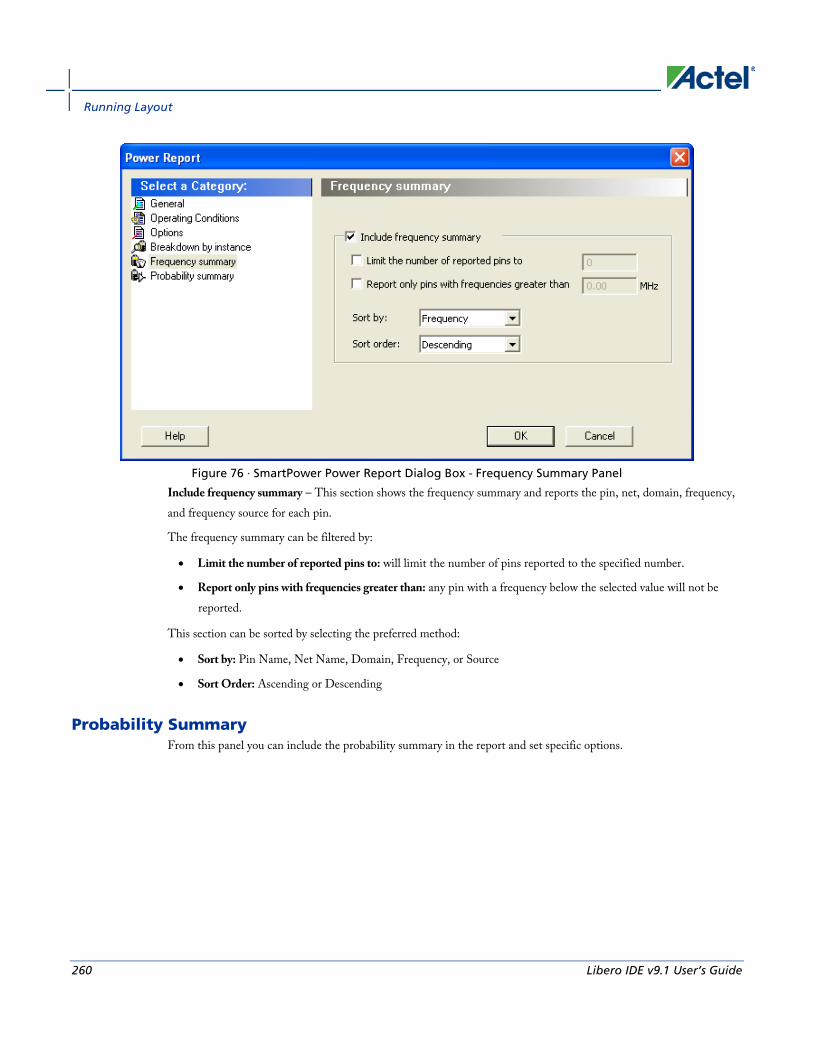
Running Layout
260 Libero IDE v9.1 User’s Guide
Figure 76 · SmartPower Power Report Dialog Box - Frequency Summary Panel
Include frequency summary – This section shows the frequency summary and reports the pin, net, domain, frequency, and frequency source for each pin.
The frequency summary can be filtered by:
• Limit the number of reported pins to: will limit the number of pins reported to the specified number.
• Report only pins with frequencies greater than: any pin with a frequency below the selected value will not be reported.
This section can be sorted by selecting the preferred method:
• Sort by: Pin Name, Net Name, Domain, Frequency, or Source
• Sort Order: Ascending or Descending
Probability Summary From this panel you can include the probability summary in the report and set specific options.
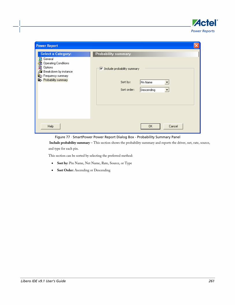
Power Reports
Libero IDE v9.1 User’s Guide 261
Figure 77 · SmartPower Power Report Dialog Box - Probability Summary Panel
Include probability summary – This section shows the probability summary and reports the driver, net, rate, source, and type for each pin.
This section can be sorted by selecting the preferred method:
• Sort by: Pin Name, Net Name, Rate, Source, or Type
• Sort Order: Ascending or Descending
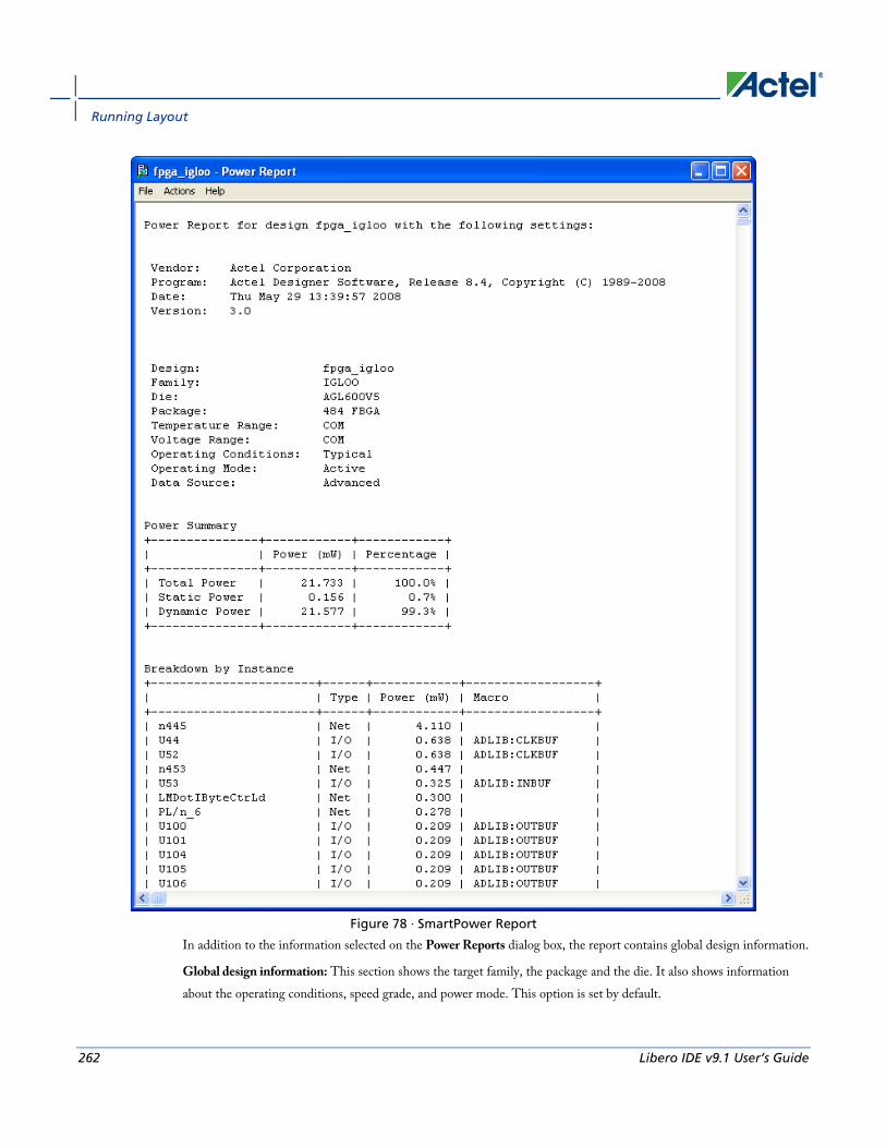
Running Layout
262 Libero IDE v9.1 User’s Guide
Figure 78 · SmartPower Report
In addition to the information selected on the Power Reports dialog box, the report contains global design information.
Global design information: This section shows the target family, the package and the die. It also shows information about the operating conditions, speed grade, and power mode. This option is set by default.

Cycle-Accurate Power Reports
Libero IDE v9.1 User’s Guide 263
See Also Report (Power)
Cycle-Accurate Power Reports Traditional power analysis based on a VCD simulation file reports an average power for the entire simulation time. Based on a VCD simulation file, the cycle-accurate power analysis will report one power value per clock period (or half-period) instead of an average power for the whole simulation. This feature allows to easily identify the worst cycle in terms of power performance; and helps to understand and further minimize power consumption by facilitating the analysis of data-dependent power variations, as well as dynamic power variations due to clock-gating, or even clock frequency variations.
To generate a cycle-accurate power report:
1. From the Designer Tools menu, choose Reports > Power > Power Cycle Accurate. The Cycle Accurate Power Report dialog box appears.
2. Select the options you want to include in the report, and then click OK. The cycle accurate power report appears in a separate window.
You can also generate the cycle accurate power report from within SmartPower. From the Tools menu, choose Reports > Cycle Accurate Power Report to open the cycle accurate power report dialog box; or select a vcd file from the Modes and Scenarios toolbar, and from the right-click menu, select Tools > Power Cycle Accurate.
The cycle-accurate power report dialog box is organized in the following panels: General, Sampling Period, Partial Parsing, Top-Level Name, Glitch Filtering, and History Size Reduction.

Running Layout
264 Libero IDE v9.1 User’s Guide
General
Figure 79 · SmartPower Cycle Accurate Power Report Dialog Box – General
VCD file - Select the VCD file you want to import.
Report format – Select Text or CSV (Comma Separated Value) as the desired export format.
Use operating conditions from – Select the mode from which the operating conditions will be used.
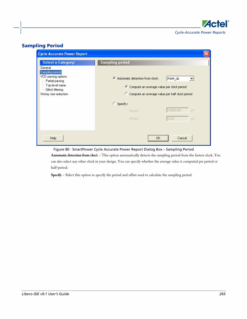
Cycle-Accurate Power Reports
Libero IDE v9.1 User’s Guide 265
Sampling Period
Figure 80 · SmartPower Cycle Accurate Power Report Dialog Box – Sampling Period
Automatic detection from clock – This option automatically detects the sampling period from the fastest clock. You can also select any other clock in your design. You can specify whether the average value is computed per period or half-period.
Specify – Select this option to specify the period and offset used to calculate the sampling period.
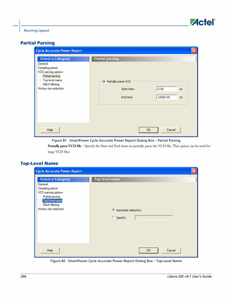
Running Layout
266 Libero IDE v9.1 User’s Guide
Partial Parsing
Figure 81 · SmartPower Cycle Accurate Power Report Dialog Box – Partial Parsing
Partially parse VCD file – Specify the Start and End times to partially parse the VCD file. This option can be used for large VCD files.
Top-Level Name
Figure 82 · SmartPower Cycle Accurate Power Report Dialog Box – Top-Level Name
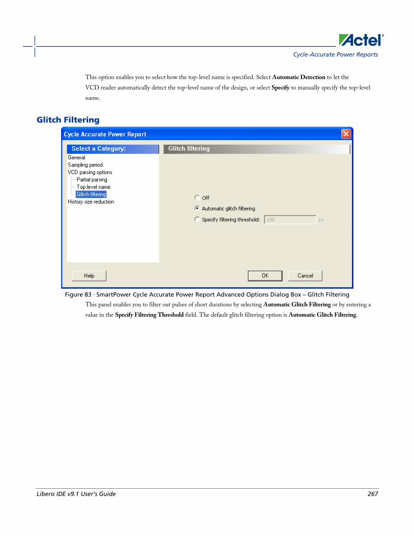
Cycle-Accurate Power Reports
Libero IDE v9.1 User’s Guide 267
This option enables you to select how the top-level name is specified. Select Automatic Detection to let the VCD reader automatically detect the top-level name of the design, or select Specify to manually specify the top-level name.
Glitch Filtering
Figure 83 · SmartPower Cycle Accurate Power Report Advanced Options Dialog Box – Glitch Filtering
This panel enables you to filter out pulses of short durations by selecting Automatic Glitch Filtering or by entering a value in the Specify Filtering Threshold field. The default glitch filtering option is Automatic Glitch Filtering.

Running Layout
268 Libero IDE v9.1 User’s Guide
History Size Reduction
Figure 84 · SmartPower Cycle Accurate Power Report Advanced Options Dialog Box – History Size Reduction
This panel enables you to limit the history size by keeping only local extrema or setting a power threshold.
The results are displayed in the cycle accurate power report below.

Activity and Hazards Reports
Libero IDE v9.1 User’s Guide 269
Figure 85 · SmartPower Cycle Accurate Power Report
Activity and Hazards Reports Traditional Power Analysis based on a VCD simulation file reports an average power value that will account for all nets switching in the design. This switching includes functional transitions and spurious transitions. Due to the delay of each gate, paths arriving at one internal gate may have different propagation delays. Therefore, a gate may exhibit
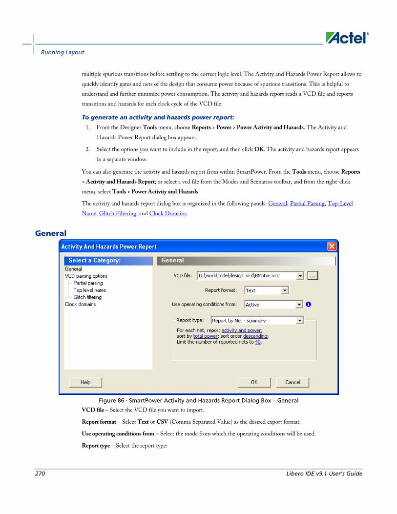
Running Layout
270 Libero IDE v9.1 User’s Guide
multiple spurious transitions before settling to the correct logic level. The Activity and Hazards Power Report allows to quickly identify gates and nets of the design that consume power because of spurious transitions. This is helpful to understand and further minimize power consumption. The activity and hazards report reads a VCD file and reports transitions and hazards for each clock cycle of the VCD file.
To generate an activity and hazards power report:
1. From the Designer Tools menu, choose Reports > Power > Power Activity and Hazards. The Activity and Hazards Power Report dialog box appears.
2. Select the options you want to include in the report, and then click OK. The activity and hazards report appears in a separate window.
You can also generate the activity and hazards report from within SmartPower. From the Tools menu, choose Reports > Activity and Hazards Report; or select a vcd file from the Modes and Scenarios toolbar, and from the right-click menu, select Tools > Power Activity and Hazards
The activity and hazards report dialog box is organized in the following panels: General, Partial Parsing, Top-Level Name, Glitch Filtering, and Clock Domains.
General
Figure 86 · SmartPower Activity and Hazards Report Dialog Box – General
VCD file – Select the VCD file you want to import.
Report format – Select Text or CSV (Comma Separated Value) as the desired export format.
Use operating conditions from – Select the mode from which the operating conditions will be used.
Report type – Select the report type:
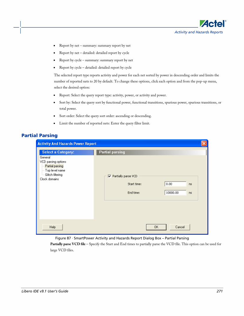
Activity and Hazards Reports
Libero IDE v9.1 User’s Guide 271
• Report by net – summary: summary report by net
• Report by net – detailed: detailed report by cycle
• Report by cycle – summary: summary report by net
• Report by cycle – detailed: detailed report by cycle
The selected report type reports activity and power for each net sorted by power in descending order and limits the number of reported nets to 20 by default. To change these options, click each option and from the pop-up menu, select the desired option:
• Report: Select the query report type: activity, power, or activity and power.
• Sort by: Select the query sort by functional power, functional transitions, spurious power, spurious transitions, or total power.
• Sort order: Select the query sort order: ascending or descending.
• Limit the number of reported nets: Enter the query filter limit.
Partial Parsing
Figure 87 · SmartPower Activity and Hazards Report Dialog Box – Partial Parsing
Partially parse VCD file – Specify the Start and End times to partially parse the VCD file. This option can be used for large VCD files.
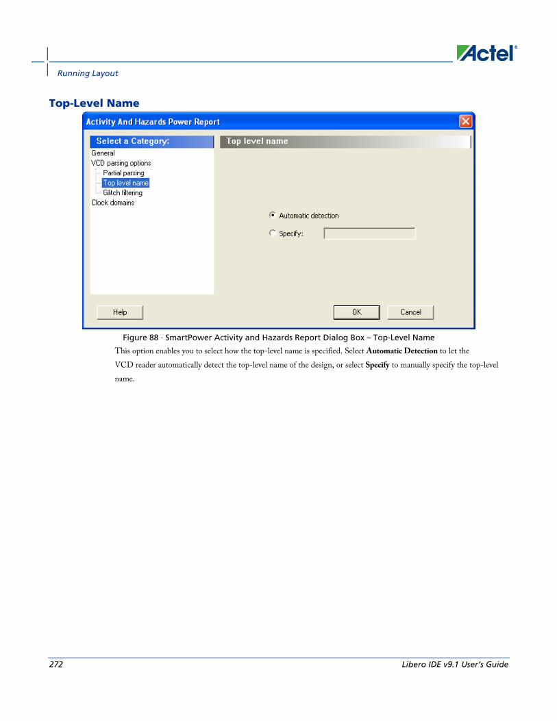
Running Layout
272 Libero IDE v9.1 User’s Guide
Top-Level Name
Figure 88 · SmartPower Activity and Hazards Report Dialog Box – Top-Level Name
This option enables you to select how the top-level name is specified. Select Automatic Detection to let the VCD reader automatically detect the top-level name of the design, or select Specify to manually specify the top-level name.

Activity and Hazards Reports
Libero IDE v9.1 User’s Guide 273
Glitch Filtering
Figure 89 · SmartPower Activity and Hazards Report Advanced Options Dialog Box – Glitch Filtering
This option enables you to filter out pulses of short durations by selecting Automatic Glitch Filtering or by entering a value in the Specify Filtering Threshold field. The default glitch filtering option is Automatic Glitch Filtering.
Clock Domains
Figure 90 · SmartPower Activity and Hazards Report Advanced Options Dialog Box – Clock Domains

Running Layout
274 Libero IDE v9.1 User’s Guide
The clock domain can be automatically constructed or it can be specified by the user.
Automatic construction – This option automatically constructs the clock domain. SmartPower automatically analyzes your design to assess if a clock is active and what is the active edge.
Specify – Select this option to specify the period and first edge.
Use the clock domain table to set the active edge (rising, falling or both) and to set a clock as transparent.
The results are displayed in the activity and hazards power report below.
Figure 91 · SmartPower Activity and Hazards Report

Scenario Power Report
Libero IDE v9.1 User’s Guide 275
Scenario Power Report The scenario power report enables you to select a previously defined scenario and calculate the average power consumption and the battery life for this scenario.
To generate a scenario power report:
Note: Note: In order to generate a scenario power report, your design must contain one or more scenarios.
1. From the Designer Tools menu, choose Reports > Power > Power Scenario. The Scenario Power Report dialog box appears.
2. Select the options you want to include in the report, and then click OK. The scenario power report appears in a separate window.
You can also generate the scenario power report from within SmartPower. From the Tools menu, choose Reports > Scenario Power Report, or click the Scenario Power Report button to open the Power Scenarios dialog box. By default, the report includes global design information and power sequencer summary. Specify which results you want to display by checking the boxes to be included in the report.
The power report dialog box is organized in the following panels: General, Operating Conditions, Options, and Battery Life.
General The general panel enables you to select what to include in the report, the report format, and the scenario you want to generate the report for.
Figure 92 · SmartPower Scenario Power Report Dialog Box – General Panel

Running Layout
276 Libero IDE v9.1 User’s Guide
Include in the Report Breakdown by Rail – This section shows the power consumption of each rail.
Breakdown by Type – This section enables reporting on the power consumption according to: gates, nets, clocks, core static, IOs, and memories.
Breakdown by Mode – This section enables reporting on the power consumption by mode.
Operating Condition Summary – This section reports the operating conditions.
Report Format Select Text or CSV (Comma Separated Value) as the desired export format.
Scenario Select a previously defined scenario to generate the report from.
Operating Conditions The Operating Conditions panel enables you to select the operating conditions case for the current design.
Figure 93 · SmartPower Scenario Power Report Dialog Box – Operating Conditions Panel
Options The Options panel enables you to select power and frequency units and to use toggle rates.

Scenario Power Report
Libero IDE v9.1 User’s Guide 277
Figure 94 · SmartPower Scenario Power Report Dialog Box – Options Panel
Units Frequency: Sets unit preferences for frequency – Hz, KHz, MHz.
Power Units: Sets unit preferences for power – W, mW, or υW.
Use Toggle Rates When toggle rates are active (Use Toggle Rates box is checked), the data frequency of all the clock domains is defined as a function of the clock frequency. This updates the data frequency automatically when you update the clock frequency. Toggle rates enable you to specify the data frequency as a percentage of clock frequency, but you can no longer specify the data frequency as a number, only as a percentage of the clock frequency. To set the data frequency again, clear the Use Toggle Rates option.
Battery Life The Battery Life panel enables reporting of the battery capacity and the battery life. Enter a battery capacity in MA/Hrs.

Running Layout
278 Libero IDE v9.1 User’s Guide
Figure 95 · SmartPower Scenario Power Report Dialog Box – Battery Life Panel
The SmartPower scenario power report returns the average power consumption and battery life for this sequence.

Scenario Power Report
Libero IDE v9.1 User’s Guide 279
Figure 96 · SmartPower Scenario Power Report
In addition to the information selected on the Scenario Power Reports dialog box, the report contains global design information, a mode summary and the sequence average power.
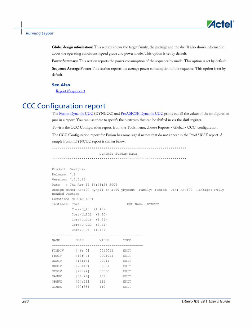
Running Layout
280 Libero IDE v9.1 User’s Guide
Global design information: This section shows the target family, the package and the die. It also shows information about the operating conditions, speed grade and power mode. This option is set by default.
Power Summary: This section reports the power consumption of the sequence by mode. This option is set by default.
Sequence Average Power: This section reports the average power consumption of the sequence. This option is set by default.
See Also Report (Sequencer)
CCC Configuration report The Fusion Dynamic CCC (DYNCCC) and ProASIC3E Dynamic CCC prints out all the values of the configuration pins in a report. You can use these to specify the bitstream that can be shifted in via the shift register.
To view the CCC Configuration report, from the Tools menu, choose Reports > Global > CCC_configuration.
The CCC Configuration report for Fusion has some signal names that do not appear in the ProASIC3E report. A sample Fusion DYNCCC report is shown below:
********************************************************************
Dynamic Stream Data
********************************************************************
Product: Designer
Release: 7.2
Version: 7.2.0.13
Date : Thu Apr 13 14:48:21 2006
Design Name: AFS600_dynpll_rc_a100_ybycout Family: Fusion Die: AFS600 Package: Fully Bonded Package
Location: MIDDLE_LEFT
Instance: Core DEF Name: DYNCCC
Core/U_P0 (1,40)
Core/U_PLL (2,40)
Core/U_GLB (1,41)
Core/U_GLC (2,41)
Core/U_P4 (1,42)
----------------------------------------------
NAME SDIN VALUE TYPE
----------------------------------------------
FINDIV [ 6: 0] 0010011 EDIT
FBDIV [13: 7] 0001011 EDIT
OADIV [18:14] 00011 EDIT
OBDIV [23:19] 00001 EDIT
OCDIV [28:24] 00000 EDIT
OAMUX [31:29] 101 EDIT
OBMUX [34:32] 111 EDIT
OCMUX [37:35] 110 EDIT

CCC Configuration report
Libero IDE v9.1 User’s Guide 281
FBSEL [39:38] 10 EDIT
FBDLY [44:40] 10100 EDIT
XDLYSEL [45] 1 EDIT
DLYGLA [50:46] 01001 EDIT
DLYGLB [55:51] 00000 EDIT
DLYGLC [60:56] 00000 EDIT
DLYYB [65:61] 10001 EDIT
DLYYC [70:66] 11100 EDIT
STATASEL [71] 1 MASKED
STATBSEL [72] 1 MASKED
STATCSEL [73] 1 MASKED
VCOSEL [76:74] 010 EDIT
DYNASEL [77] 0 MASKED
DYNBSEL [78] 1 MASKED
DYNCSEL [79] 1 MASKED
RESETEN [80] 1 READONLY
RXASEL [81] 0 MASKED
RXBSEL [82] 0 MASKED
RXCSEL [83] 0 MASKED
OADIVHALF [84] 0 EDIT
OBDIVHALF [85] 0 EDIT
OCDIVHALF [86] 0 EDIT
GLMUXCFG [88:87] 00 MASKED
A sample ProASIC3E DYNCCC report is shown below.
********************************************************************
Dynamic Stream Data
********************************************************************
Product: Designer
Release: 7.2
Version: 7.2.0.0
Date : Tue May 02 15:50:01 2006
Design Name: dynccc Family: Proasic3E Die: A3PE600 Package: Fully Bonded Package
Location: MIDDLE_RIGHT
Instance: I_dynccc DEF Name: DYNCCC
I_dynccc/U_DYN (196,40)
I_dynccc/U_PLL (195,40)
I_dynccc/U_GLB (196,41)
I_dynccc/U_GLC (195,41)
----------------------------------------------
NAME SDIN VALUE TYPE
----------------------------------------------
FINDIV [ 6: 0] 1100101 EDIT
FBDIV [13: 7] 0000110 EDIT
OADIV [18:14] 00101 EDIT
OBDIV [23:19] 00101 EDIT
OCDIV [28:24] 00101 EDIT
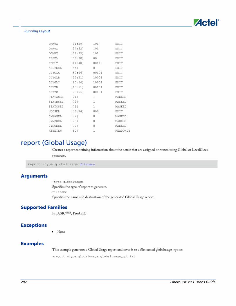
Running Layout
282 Libero IDE v9.1 User’s Guide
OAMUX [31:29] 101 EDIT
OBMUX [34:32] 101 EDIT
OCMUX [37:35] 101 EDIT
FBSEL [39:38] 00 EDIT
FBDLY [44:40] 00110 EDIT
XDLYSEL [45] 0 EDIT
DLYGLA [50:46] 00101 EDIT
DLYGLB [55:51] 10001 EDIT
DLYGLC [60:56] 10001 EDIT
DLYYB [65:61] 00101 EDIT
DLYYC [70:66] 00101 EDIT
STATASEL [71] 1 MASKED
STATBSEL [72] 1 MASKED
STATCSEL [73] 1 MASKED
VCOSEL [76:74] 000 EDIT
DYNASEL [77] 0 MASKED
DYNBSEL [78] 0 MASKED
DYNCSEL [79] 0 MASKED
RESETEN [80] 1 READONLY
report (Global Usage) Creates a report containing information about the net(s) that are assigned or routed using Global or LocalClock resources.
report -type globalusage filename
Arguments -type globalusage
Specifies the type of report to generate. filename
Specifies the name and destination of the generated Global Usage report.
Supported Families ProASICPLUS, ProASIC
Exceptions • None
Examples This example generates a Global Usage report and saves it to a file named globalusage_rpt.txt:
>report -type globalusage globalusage_rpt.txt

Global Usage report
Libero IDE v9.1 User’s Guide 283
See Also Global Usage report
Tcl documentation conventions
Global Usage report The Global Usage report provides information about the net(s) that are assigned or routed using Global or LocalClock resources.
You can generate this report in either pre or post route state of the design.
In pre-routed state, the Global Usage report displays the following information:
• Net(s) assigned to Global resources
• Net(s) assigned to LocalClock resources
In post-routed state, the Global Usage report displays the following information:
• Net(s) that are routed using Global resources
• Net(s) that are routed using LocalClock resources
• Net(s) that are constrained to use LocalClock resources but routed using Regular resources. In this case, the tool displays a warning message at the end of the report.
To create a Global Usage report:
From the Tools menu, choose Reports > Global > GlobalUsage.
See Also report (Global Usage) Tcl command
Designer Block Report The Designer Block report is available in Tools > Reports > Block. It includes a compile, global, datasheet, and interface report and Designer Block-related information.
The block reports are available in the Project Manager Files tab after you generate your block and instantiate it in your project. Double-click the report to view the contents.
In the Project Manager there is a header_report.log that contains only the options used to generate the block. This information is available in each report you generate from the Designer > Tools menu.
Compile Use it to evaluate resources and manage the globals in the other blocks and the <top> design (if necessary).

Running Layout
284 Libero IDE v9.1 User’s Guide
Datasheet Lists block timing and I/O placement information. If the block is preserved during instantiation (both placement and routing) you can expect to get the same results as are shown in this report.
Global Lists global usage in the block. Useful if you want to evaluate the globals used by the block / manage globals in the overall design.
Interface The Interface section lists:
• Connection information for interface macros connected to the block ports
• Block placement information, including each port and its fanout, type (pad, clock, global, etc.), direction, and name
• Information on legal move locations, useful if you are instantiating multiple blocks in one design
Compile report The Compile Report appears in the Designer Log window after compile is complete. It is divided into the following sections:
Parameters used to run Compile All the information about the design, including the device selection and compile options used to run compile. Some options are not shown if you did not select them; for example, if the option demote_globals is OFF than the option demote_globals_max_fanout does not appear in the report.
Warnings, Errors, and the Netlist Optimization Report Lists any warnings or errors encountered during compile. Also contains the Netlist Optimization report that lists out the optimized macros (deleted blocks) in your design.
Reading user pdc (Physical Design Constraints) file(s) postcompile Lists out any PDC related errors and warnings encountered during compile.
Compile Report - Device utilization report The Device Utilization Report includes the following:
• Complete device utilization: Summary for all the resources used in the final optimized netlist.
• Global Information: Describes the number of chip and quadrant clocks in the design and the device.
• Core Information: Describes the total number of macros in the netlist and how many tiles they are using.

Compile report
Libero IDE v9.1 User’s Guide 285
• I/O function: Detailed information about I/O's, such as how many Diff I/Os exist in the netlist, etc.
• I/O Technology: Summary of I/O technology used in the netlist.
• I/O Bank Resource Usage: Summarizes each I/O bank, including details on voltages, I/O pairs, Vref I/Os, Vref Pins, etc.
• I/O Voltage Usage: Lists I/Os by voltage used in the netlist and device resources available for each voltage (using the iobank and placement information).
Net information report The section may not appear if there is no net to report. The Net Information Report includes the following sections:
• List of nets that drive enable flip-flops that have been remapped to a 2-tile implementation
• List of nets that have been assigned to a chip global resource
• List of nets that have been assigned to a quadrant global resource
• List of nets that nets have been assigned to a LocalClock resource using PDC constraints
• High fanout nets in the post-compile netlist
• Nets that are candidates for clock assignment and the resulting fanout
Note: Note: If the driver macro of a clock net is fixed in a quadrant clock location then this net will show in the quadrant clock net report.
Note: The number of clock nets (chip+quadrant) can be less than the number reported in the device utilization (such as in the case of PLL using a YB and not the GLB).
Net Information Report Types
INT_NET - Internal nets
CLK_NET - More than 75% of pins driven by this net are clock pins
SET/RESET_NET - More than 75% of pins driven by this net are set or reset pins
Net Information Source Types:
NETLIST - Clock from the netlist
PDC PROMOTED - Promoted because of a PDC constraint
AUTO PROMOTED - Promoted automatically by compile; change the compile options if you do not want to promote this net.
ESSENTIAL - Global clock from the netlist that cannot be demoted (such as the PLL or CLKBIBUF).
Net Information Report Region (Definition)
The region is the clock region for the local and quadrant clocks. For example, Local clock regions chip_T1, chip_T2:B5, quandrant_T1
The quadrant clock regions list is as follows: quadrant_UL, quadrant_UR, quadrant_LL, quadrant_LR

Running Layout
286 Libero IDE v9.1 User’s Guide
Block information report This section lists the name of the module, the name of the instance, the number of macros and nets used in your block(s), and information on how conflicts between blocks were resolved (if any).

Starting Silicon Sculptor from Libero IDE
Libero IDE v9.1 User’s Guide 287
Device Programming
Once you have completed your design, and you are satisfied with the back-annotated timing simulation, create your programming file. Depending upon your device family, you need to generate a Fuse, Bitstream or STAPL programming file.
IGLOO, ProASIC3, SmartFusion and Fusion devices use the FlashPoint program file generator to create a programming file. The FlashPoint interface enables the advanced security features in all three device families.
Programmer Antifuse Programming File Flash Programming File
FlashPro4/3/3x N/A *.stp
Silicon Sculptor I *.afm (Non-Axcelerator families) *.bit
Silicon Sculptor II *.afm *.bit *.stp (Windows only)
Starting Silicon Sculptor from Libero IDE Before starting Silicon Sculptor, generate your programming file.
To start the programming tool software:
1. Right-click the design root file in the Hierarchy tab.
2. Click Run Silicon Sculptor. Refer to the Silicon Sculptor User’s Guide for information on using the programming tool.
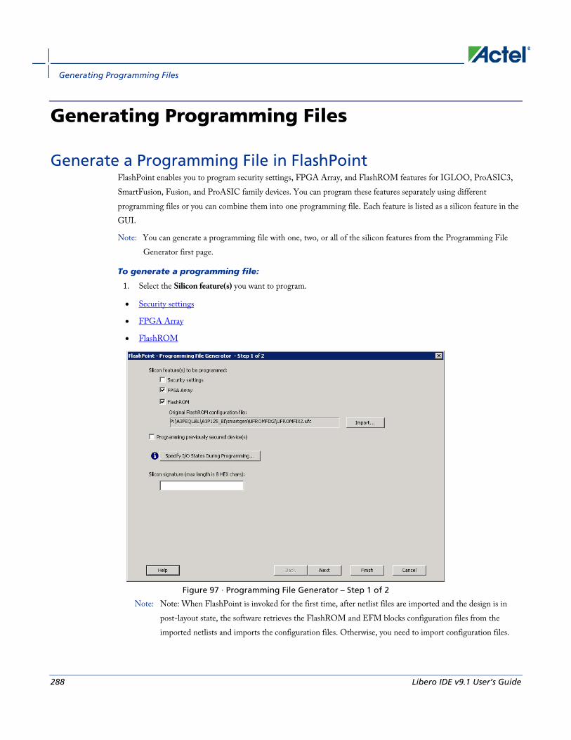
Generating Programming Files
288 Libero IDE v9.1 User’s Guide
Generating Programming Files
Generate a Programming File in FlashPoint FlashPoint enables you to program security settings, FPGA Array, and FlashROM features for IGLOO, ProASIC3, SmartFusion, Fusion, and ProASIC family devices. You can program these features separately using different programming files or you can combine them into one programming file. Each feature is listed as a silicon feature in the GUI.
Note: You can generate a programming file with one, two, or all of the silicon features from the Programming File Generator first page.
To generate a programming file:
1. Select the Silicon feature(s) you want to program.
• Security settings
• FPGA Array
• FlashROM
Figure 97 · Programming File Generator – Step 1 of 2
Note: Note: When FlashPoint is invoked for the first time, after netlist files are imported and the design is in post-layout state, the software retrieves the FlashROM and EFM blocks configuration files from the imported netlists and imports the configuration files. Otherwise, you need to import configuration files.
Generate a Programming File in FlashPoint
Libero IDE v9.1 User’s Guide 289
2. Click the Programming previously secured device(s) check box if you are reprogramming a device that has been secured.
Because the IGLOO, ProASIC3, SmartFusion, Fusion, and ProASIC families enable you to program the Security Settings separately from the FPGA Array and/or FlashROM, you must indicate if the Security Settings were previously programmed into the target device. This requirement also applies when you generate programming files for reprogramming.
3. Enter the silicon signature (0-8 HEX characters). See Silicon Signature for more information.
4. Depending upon the Silicon features you selected, click Next or Finish.
If you click Next, follow the instructions in the appropriate dialog box. If you click Finish, the Generate Programming Files dialog box appears (as shown in the figure below). Use this dialog box box to specify the programming file name, location, output format (STAPL file, SVF file, PDB file, DirectC DAT file, 1532 file), and, if necessary, limit the file size (as explained below).
Some testers may have memory size restrictions for a single SVF file. The SVF limit file option enables you to limit the size of each SVF file by either file size or vectors.
The generated SVF files append an index to the file name indicating the sequence of files. The format is:
<SVF_filename>_XXXXX.svf
where XXXXX is the index of the SVF file. The first SVF file begins with <SVF_filename>_00000.svf and increments by 1 until file generation is complete.
Maximum file size: Max file size limit for the SVF file; use this option to limit your SVF file size based on number of kB.
Maximum number of vectors: Max vector limit for the SVF file; use this option to limit the size of your SVF based on number of vectors.
For more information on DAT files, refer to the Data File Generator (DatGen) section of the DirectC User's Guide.

Generating Programming Files
290 Libero IDE v9.1 User’s Guide
Figure 98 · Generate Programming Files Dialog Box (Flashpoint)
Generate a Programming File for SmartFusion You can configure and generate a new PDB file from FlashPoint.
If you are using Single Mode, click Create to add a new PDB, or click Modify to make changes to a loaded PDB.
In Chain Mode, if you have not already done so, construct a chain and click Create PDB to create a new PDB for programming, or click Modify PDB to make changes to a loaded PDB.
FlashPoint enables you to specify your security settings and silicon features when you generate your programming file in SmartFusion. You can specify your FPGA Array, FlashROM, and Embedded Flash Memory by importing FDB, UFC and EFC files, respectively (as shown in the figure below). If you have imported a FlashROM and Embedded Flash Memory file you can click Modify to configure these feature before saving your PDB file.
Click Specify I/O States During Programming to set custom I/O states.
Note: NOTE: You must import an FDB to populate Port Name and Macro Cell columns.

Generate a Programming File for SmartFusion
Libero IDE v9.1 User’s Guide 291
Figure 99 · FlashPoint Programming Settings for SmartFusion

Generating Programming Files
292 Libero IDE v9.1 User’s Guide
Generate a Programming File for CoreMP7/Cortex-M1 Device Support
FlashPoint enables you to program FPGA Array and FlashROM features for CoreMP7/Cortex-M1 devices. You can program these features separately using different programming files or you can combine them into one programming file. Each feature is listed as a silicon feature in the GUI. You can generate a programming file with one, two, or all of the silicon features from the Programming File Generator first page. For CoreMP7/Cortex-M1 device support, you cannot select your own security settings. The generated programming file always has the encrypted FPGA Array content. The programming file generation is the same as the ProASIC3 family devices.
To generate a programming file:
1. Select the Silicon feature(s) you want to program.
FPGA Array
FlashROM
2. Click Next or Finished depending on the silicon features you selected.
If you click Next, follow the instructions in the appropriate dialog box. If you click Finish, the Generate Programming Files dialog box appears. Use this dialog box box to specify the programming file name, location, and output format (STAPL file, SVF file, PDB file, DirectC DAT file, 1532 file).
For more information on DAT files, refer to the Data File Generator (DatGen) section of the DirectC User's Guide.
CoreMP7/Cortex-M1 Device Security CoreMP7/Cortex-M1 devices are shipped with the following security enabled:
• FPGA Array enabled for AES encrypted programming and verification.
• FlashROM enabled for plain text read and write.
You cannot select your own security settings. The generated programming file includes the encrypted FPGA Array content.
Programming FlashROM and FPGA Array For CoreMP7/Cortex-M1 device support, the programming generation for FlashROM and FPGA Array is the same as the programming generation for ProASIC3 and ProASIC family devices.

Generate a Programming File for AFS Device Support - Designer Only
Libero IDE v9.1 User’s Guide 293
Generate a Programming File for AFS Device Support - Designer Only
FlashPoint enables you to program Security Settings, FPGA Array, Embedded Flash Memory Blocks, and FlashROM features for AFS device support. You can program these features separately using different programming files or you can combine them into one programming file. Each feature is listed as a silicon feature in the GUI. You can generate a programming file with one, two, or all of the silicon features from the Programming File Generator first page.
AFS Programming In addition to FPGA Array, FlashROM and security setting, the Fusion devices provide Embedded Flash Memory
Blocks (FB) for both Analog configuration initialization and regular memory storage. Depending on the targeted AFS device, you may have one, two, or four FBs available to you. FlashPoint enables you to initialize the FB Instance(s), as desribed in the Embedded Flash Memory help.
To generate a programming file:
1. Select the Silicon feature(s) you want to program.
Security Settings
FPGA Array
FlashROM
Embedded Flash Memory Block

Generating Programming Files
294 Libero IDE v9.1 User’s Guide
Figure 100 · FlashPoint- Programming File Generator for AFS
Note: Note: Check the check box in the Program column to enable block modification.
2. Check the Programming previously secured devices(s) box if you want to program previously secured devices.
3. Enter the Silicon signature.
4. Depending upon the Silicon features you selected, click Finish or Next.
If you click Next, follow the instructions in the appropriate dialog box. If you click Finish, the Generate Programming Files dialog box appears. Use this dialog box box to specify the programming file name, location, and output format (STAPL file, SVF file, PDB file, DirectC DAT file, 1532 file).
For more information on DAT files, refer to the Data File Generator (DatGen) section of the DirectC User's Guide.
Programming Security Settings, FlashROM, and FPGA Array For AFS device support, the programming generation for Security Settings, FlashROM and FPGA Array is the same as the programming generation for ProASIC3 family devices.
Generate a Programming File for Serialization Support in In House Programming (IHP)
Libero IDE v9.1 User’s Guide 295
Generate a Programming File for Serialization Support in In House Programming (IHP)
FlashPoint allows you to program security settings, FPGA Array, and FlashROM features for IGLOO, ProASIC3, SmartFusion, Fusion, and ProASIC family devices. You can program these features separately using different programming files or you can combine them into one programming file. Each feature is listed as a silicon feature in the GUI.
SVF Serialization Support in IHP In addition to FPGA Array, FlashROM, and security setting, FlashPoint supports generating SVF files with serialization support in IHP.
To generate SVF with serialization support:
1. Select the Silicon feature(s) you want to program.
• Security settings
• FPGA Array
• FlashROM
• Programming Embedded Flash Memory Block
2. Import the UFC file which contains serialization data to FlashROM. Click Next.
3. Type in the number of devices to program (as shown in the figure below).
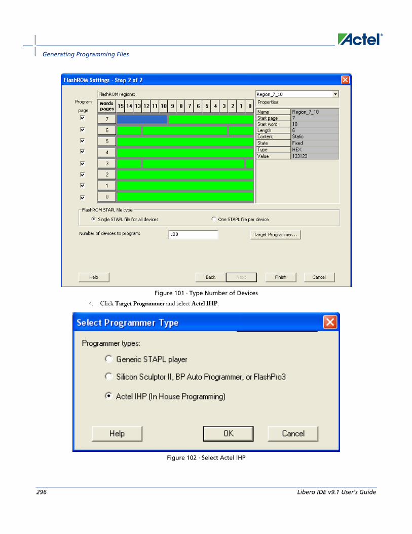
Generating Programming Files
296 Libero IDE v9.1 User’s Guide
Figure 101 · Type Number of Devices
4. Click Target Programmer and select Actel IHP.
Figure 102 · Select Actel IHP

Creating a Programming Database (PDB) File in Designer
Libero IDE v9.1 User’s Guide 297
5. Click OK. The Generate Programming Files window appears (as shown in the figure below). Select Serial Vector Files (*.svf).
Select Serial Vector Files
6. Click Generate. An Actel-specific SVF file will be generated with a corresponding serialization data file.
Note: Note: Generated SVF files will only work with IHP.
Creating a Programming Database (PDB) File in Designer The programming database (PDB) file supports IGLOO, ProASIC3, SmartFusion and Fusion devices only. This allows reconfiguration of the security settings, FlashROM, FPGA Array, and Embedded Flash Memory Blocks. You create the file in Designer using FlashPoint and you modify the file in FlashPro.
You must create programming files for SmartFusion in FlashPro; see the Generate a Programming File for SmartFusion topic for more information.
1. From the Designer main window, click the Programming File button. This brings up FlashPoint (see figure below).

Generating Programming Files
298 Libero IDE v9.1 User’s Guide
Figure 103 · FlashPoint Programming File Generator - PDB File
2. Select the silicon feature(s) to be programmed: Security Settings, FPGA array, FlashROM, and Embedded Flash Memory Block. If you are programming a previously secured device, check the Programming previously secured device(s) and enter the silicon signature.
3. Click Finish to create the PDB file.
See Also Configuring security and FlashROM settings in FlashPro
Configuring security settings in FlashPro
Configuring FPGA array settings
Configuring FlashROM settings in FlashPro
Configuring Embedded Flash Memory Block settings in FlashPro
Programming Embedded Flash Memory Block For more information about the Embedded Flash Memory Block, see the Flash Memory System Builder online help.

Programming the FlashROM
Libero IDE v9.1 User’s Guide 299
To program the Embedded Flash Memory Block:
1. Check the Program box to enable Embedded Flash Memory Block modification.
2. Click the Modify button to import Embedded Flash Memory Block configuration and memory content.
The Modify Embedded Flash Memory Block dialog box appears.
Figure 104 · Modify Embedded Flash Memory Block Content Dialog Box
3. Click the Import Configuration File button (if available) to import the Embedded Flash Memory Block configuration and memory content from the EFC file. This will populate the client table below. All clients that belong to this block will be selected by default.
4. Click the Import content button if you want to change the client memory content.
5. Click OK.
Note: Note: FlashPoint audits original configuration and memory content files and warns you if the files cannot be located or if they have been updated.
Programming the FlashROM You can program selected memory pages and specify the region values of the FlashROM.
• Single STAPL file for all devices: generates one programming file with all the generated increment values or with values in the custom serialization file.
• One STAPL file per device: generates one programming file for each generated increment value or for each value in the custom serialization file.
1. Select your target Programmer type.
• Select Generic STAPL Player when generating STAPL files for generic STAPL players.
• Select Silicon Sculptor II, BP Auto Programmer, or FlashPro4/3x/3 when generating programming files for those programmers.

Generating Programming Files
300 Libero IDE v9.1 User’s Guide
• Select Actel IHP (In House Programming) when generating STAPL or SVF files for Actel IHP.
2. Click OK. FlashPoint generates your programming file.
Note: Note: You cannot change the FlashROM region configuration from FlashPoint. You can only change the configuration from the FlashROM core generator.
For more information, click the Help button in FlashROM.
To program FlashROM:
1. Select FlashROM from the Generate Programming File page.
2. Enter the location of the FlashROM configuration file. The FlashROM Settings page appears (see figure below).
Figure 105 · FlashROM Settings
3. Select the FlashROM memory page that you want to program.
4. Enter the data value for the configured regions.
5. If you selected the region with a Read From File, specify the file location.
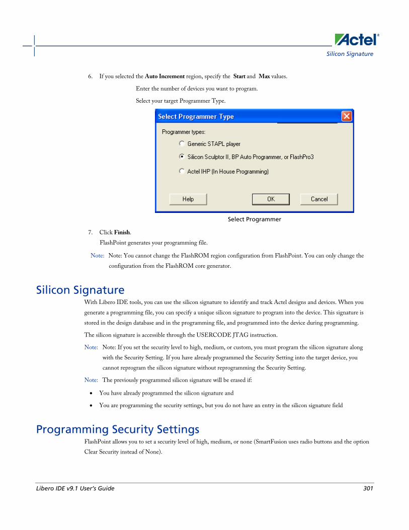
Silicon Signature
Libero IDE v9.1 User’s Guide 301
6. If you selected the Auto Increment region, specify the Start and Max values.
Enter the number of devices you want to program.
Select your target Programmer Type.
Select Programmer
7. Click Finish. FlashPoint generates your programming file.
Note: Note: You cannot change the FlashROM region configuration from FlashPoint. You can only change the configuration from the FlashROM core generator.
Silicon Signature With Libero IDE tools, you can use the silicon signature to identify and track Actel designs and devices. When you generate a programming file, you can specify a unique silicon signature to program into the device. This signature is stored in the design database and in the programming file, and programmed into the device during programming.
The silicon signature is accessible through the USERCODE JTAG instruction.
Note: Note: If you set the security level to high, medium, or custom, you must program the silicon signature along with the Security Setting. If you have already programmed the Security Setting into the target device, you cannot reprogram the silicon signature without reprogramming the Security Setting.
Note: The previously programmed silicon signature will be erased if:
• You have already programmed the silicon signature and
• You are programming the security settings, but you do not have an entry in the silicon signature field
Programming Security Settings FlashPoint allows you to set a security level of high, medium, or none (SmartFusion uses radio buttons and the option Clear Security instead of None).

Generating Programming Files
302 Libero IDE v9.1 User’s Guide
To program Security Settings on the device:
1. If you choose to program Security Settings on the device from the Generate Programming File page, the wizard takes you to the Security Settings page. Your Security Settings page depends on your family.
2. Set the security level for FPGA and FlashROM (see the table below for a description of the security levels).
Table 7 · FPGA and FlashROM Security Levels
Security Level
Security Option Description
High Protect with a 128-bit Advanced Encryption Standard (AES) key and a Pass Key
Access to the device is protected by an AES Key and the Pass Key. The Write and Verify operations of the FPGA Array use a 128-bit AES encrypted bitstream. From the JTAG interface, the Write and Verify operations of the FlashROM use a 128-bit AES encrypted bitstream. Read back of the FlashROM content via the JTAG interface is protected by the Pass Key. Read back of the FlashROM content is allowed from the FPGA Array.
Medium Protect with Pass Key The Write and Verify operations of the FPGA Array require a Pass Key. From the JTAG interface, the Read and Write operations on the FlashROM content require a Pass Key. You can Verify the FlashROM content via the JTAG interface without a Pass Key. Read back of the FlashROM content is allowed from the FPGA Array.
None No security The Write and Verify operations of the FPGA Array do not require keys. The Read, Write, and Verify operations of the FlashROM content also do not require keys. This option is available for SmartFusion; to choose it, de-select the Security Settings checkbox.

Custom Security Levels
Libero IDE v9.1 User’s Guide 303
3. Enter the Pass Key and/ or the AES Key as appropriate. You can generate a random key by clicking the Generate random key button.
The Pass Key protects all the Security Settings for the FPGA Array and/or FlashROM. The AES Key decrypts FPGA Array and/or FlashROM programming file content. Use the AES Key if you intend to program the device at an unsecured site or if you plan to update the design at a remote site in the future.
You can also customize the security levels by clicking the Custom Level button. For more information, see the Custom Security Levels section.
Custom Security Levels For advanced use, you can customize your security levels.
To set custom security levels:
1. Click the Custom Level button in the Security Settings page. The Custom Security Level dialog box appears.
2. Select the FPGA Array Security and the FlashROM Security levels. ForSmartFusion and Fusion devices, you can also choose the Embedded Flash Memory Block level of security. The FPGA Array and the FlashROM can have different Security Settings. See the tables below for a description of the custom security option levels for FPGA Array and FlashROM.
Table 8 · FPGA Array
Security Option Description
Lock for both writing and verifying
Allows writing/erasing and verification of the FPGA Array via the JTAG interface only with a valid Pass Key.
Lock for writing
Allows the writing/erasing of the FPGA Array only with a valid Pass Key. Verification is allowed without a valid Pass Key.
Use the AES Key for both writing and verifying
Allows the writing/erasing and verification of the FPGA Array only with a valid AES Key via the JTAG interface. This configures the device to accept an encrypted bitstream for reprogramming and verification

Generating Programming Files
304 Libero IDE v9.1 User’s Guide
Security Option Description
of the FPGA Array. Use this option if you intend to complete final programming at an unsecured site or if you plan to update the design at a remote site in the future. Accessing the device security settings requires a valid Pass Key.
Allow write and verify
Allows writing/erasing and verification of the FPGA Array with plain text bitstream and without requiring a Pass Key or an AES Key. Use this option when you develop your product in-house.
Note: Note: The ProASIC3 family FPGA Array is always read protected regardless of the Pass Key or the AES Key
protection.
Table 9 · FlashROM
Security Option Description
Lock for both reading and writing
Allows the writing/erasing and reading of the FlashROM via the JTAG interface only with a valid Pass Key. Verification is allowed without a valid Pass Key.
Lock for writing
Allows the writing/erasing of the FlashROM via the JTAG interface only with a valid Pass Key. Reading and verification is allowed without a valid Pass Key.
Use the AES Key for both writing and verifying Allows the writing/erasing and verification of the FlashROM via the JTAG interface only with
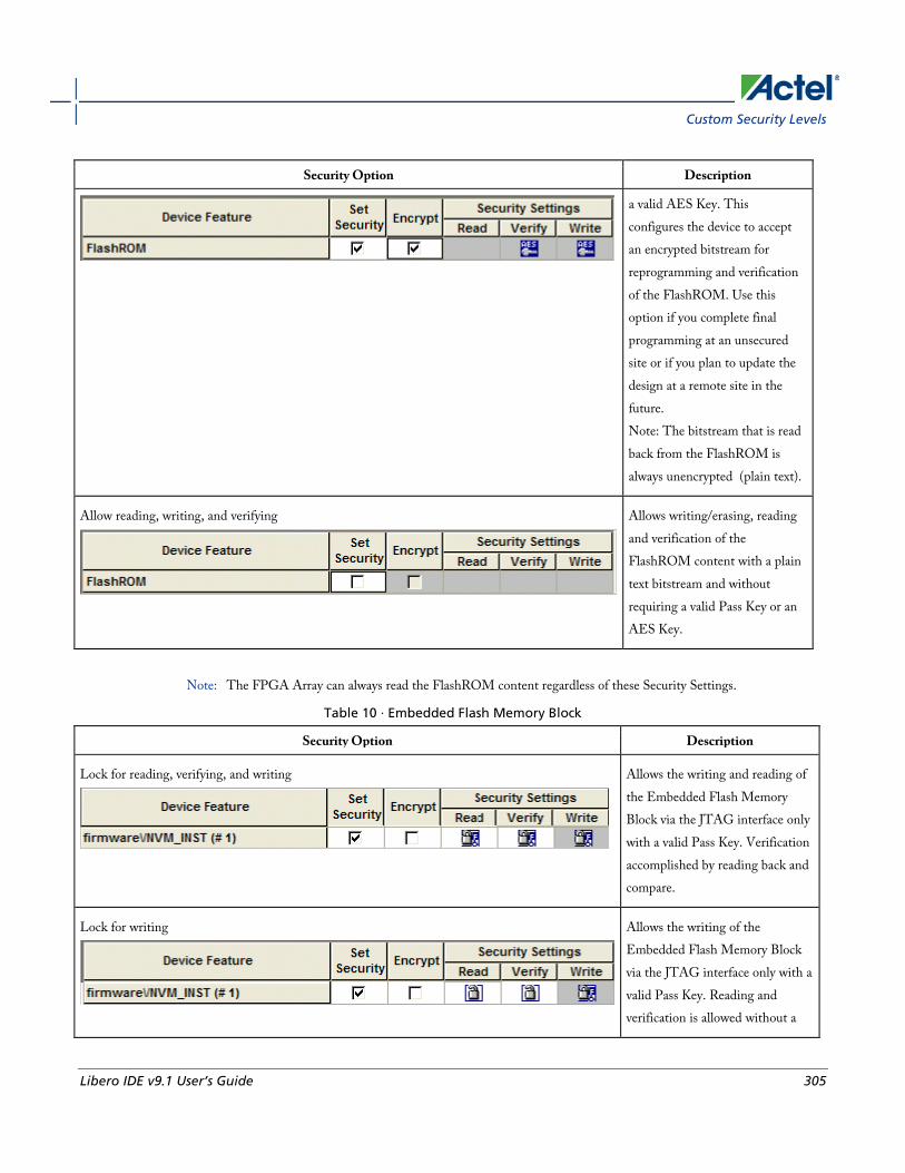
Custom Security Levels
Libero IDE v9.1 User’s Guide 305
Security Option Description
a valid AES Key. This configures the device to accept an encrypted bitstream for reprogramming and verification of the FlashROM. Use this option if you complete final programming at an unsecured site or if you plan to update the design at a remote site in the future. Note: The bitstream that is read back from the FlashROM is always unencrypted (plain text).
Allow reading, writing, and verifying
Allows writing/erasing, reading and verification of the FlashROM content with a plain text bitstream and without requiring a valid Pass Key or an AES Key.
Note: The FPGA Array can always read the FlashROM content regardless of these Security Settings.
Table 10 · Embedded Flash Memory Block
Security Option Description
Lock for reading, verifying, and writing
Allows the writing and reading of the Embedded Flash Memory Block via the JTAG interface only with a valid Pass Key. Verification accomplished by reading back and compare.
Lock for writing
Allows the writing of the Embedded Flash Memory Block via the JTAG interface only with a valid Pass Key. Reading and verification is allowed without a
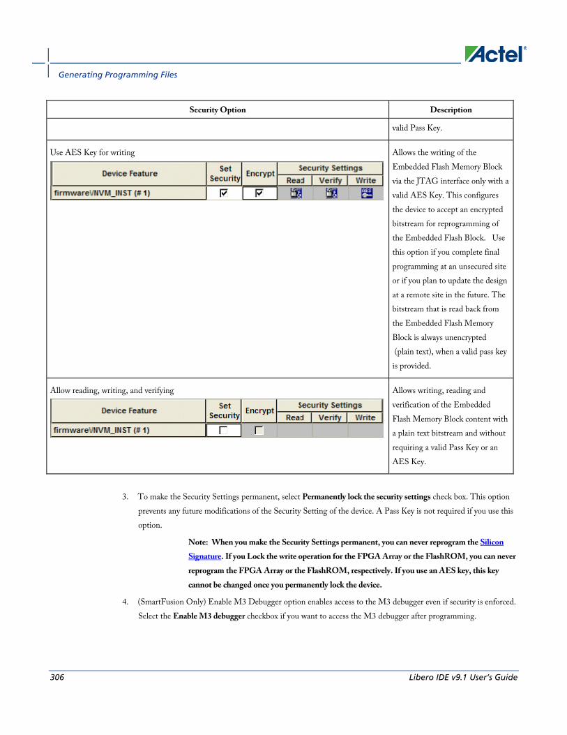
Generating Programming Files
306 Libero IDE v9.1 User’s Guide
Security Option Description
valid Pass Key.
Use AES Key for writing
Allows the writing of the Embedded Flash Memory Block via the JTAG interface only with a valid AES Key. This configures the device to accept an encrypted bitstream for reprogramming of the Embedded Flash Block. Use this option if you complete final programming at an unsecured site or if you plan to update the design at a remote site in the future. The bitstream that is read back from the Embedded Flash Memory Block is always unencrypted (plain text), when a valid pass key is provided.
Allow reading, writing, and verifying
Allows writing, reading and verification of the Embedded Flash Memory Block content with a plain text bitstream and without requiring a valid Pass Key or an AES Key.
3. To make the Security Settings permanent, select Permanently lock the security settings check box. This option
prevents any future modifications of the Security Setting of the device. A Pass Key is not required if you use this option.
Note: When you make the Security Settings permanent, you can never reprogram the Silicon Signature. If you Lock the write operation for the FPGA Array or the FlashROM, you can never reprogram the FPGA Array or the FlashROM, respectively. If you use an AES key, this key cannot be changed once you permanently lock the device.
4. (SmartFusion Only) Enable M3 Debugger option enables access to the M3 debugger even if security is enforced. Select the Enable M3 debugger checkbox if you want to access the M3 debugger after programming.
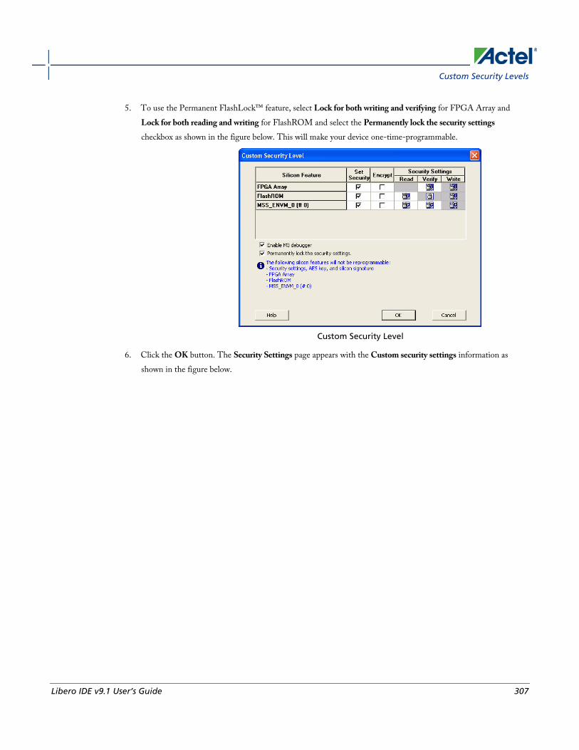
Custom Security Levels
Libero IDE v9.1 User’s Guide 307
5. To use the Permanent FlashLock™ feature, select Lock for both writing and verifying for FPGA Array and Lock for both reading and writing for FlashROM and select the Permanently lock the security settings checkbox as shown in the figure below. This will make your device one-time-programmable.
Custom Security Level
6. Click the OK button. The Security Settings page appears with the Custom security settings information as shown in the figure below.
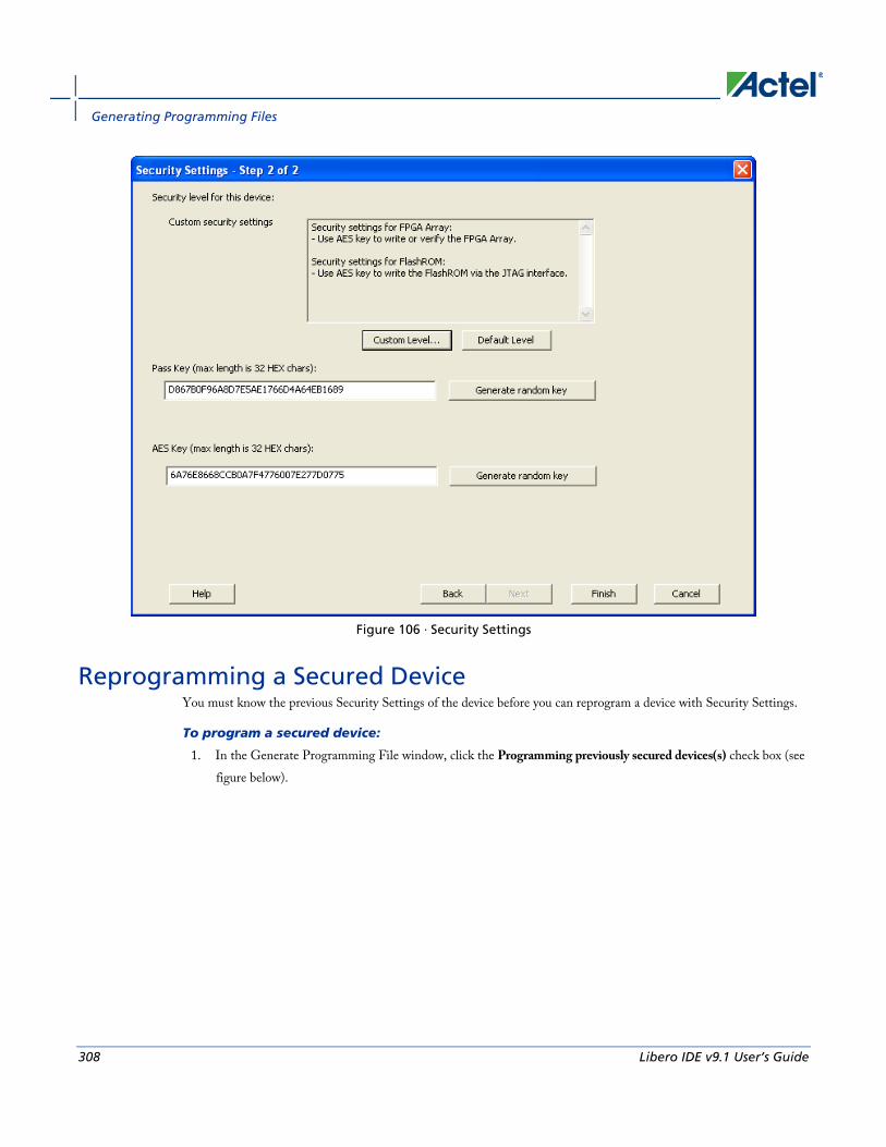
Generating Programming Files
308 Libero IDE v9.1 User’s Guide
Figure 106 · Security Settings
Reprogramming a Secured Device You must know the previous Security Settings of the device before you can reprogram a device with Security Settings.
To program a secured device:
1. In the Generate Programming File window, click the Programming previously secured devices(s) check box (see figure below).

Reprogramming a Secured Device
Libero IDE v9.1 User’s Guide 309
Figure 107 · Generate Programming File
2. Specify the previously programmed security setting for the FlashROM and/or the FPGA Array. To generate a programming file for encrypted programming please ensure that the Security settings checkbox is unchecked.
3. If you programmed the device with a custom security level, click the Custom Level button to open the Custom security dialog box, and select the Security Settings for the FPGA Array or the FlashROM that you programmed (see figure below).
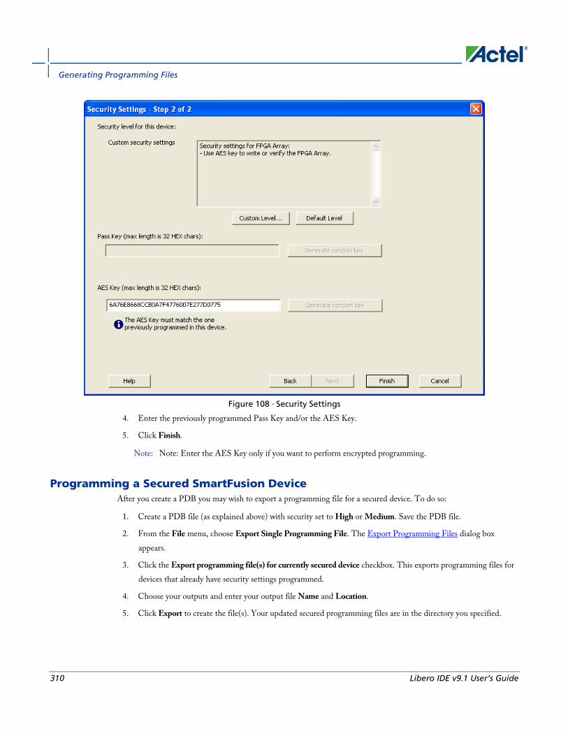
Generating Programming Files
310 Libero IDE v9.1 User’s Guide
Figure 108 · Security Settings
4. Enter the previously programmed Pass Key and/or the AES Key.
5. Click Finish.
Note: Note: Enter the AES Key only if you want to perform encrypted programming.
Programming a Secured SmartFusion Device After you create a PDB you may wish to export a programming file for a secured device. To do so:
1. Create a PDB file (as explained above) with security set to High or Medium. Save the PDB file.
2. From the File menu, choose Export Single Programming File. The Export Programming Files dialog box appears.
3. Click the Export programming file(s) for currently secured device checkbox. This exports programming files for devices that already have security settings programmed.
4. Choose your outputs and enter your output file Name and Location.
5. Click Export to create the file(s). Your updated secured programming files are in the directory you specified.

Custom Serialization Data for FlashROM Region
Libero IDE v9.1 User’s Guide 311
Custom Serialization Data for FlashROM Region FlashPoint enables you to specify a custom serialization file as a source to provide content for programming into a Read from file FlashROM region. You can use this feature for serializing the target device with a custom serialization scheme.
To specify a FlashROM region:
1. From the Properties section in the FlashROM Settings page, select the file name of the custom serialization file (see figure below). For more information on custom serialization files, see Custom Serialization Data File Format.
Figure 109 · FlashROM Settings
2. Select the FlashROM programming file type you want to generate from the two options below:
• Single programming file for all devices option: generates one programming file with all the values in the custom serialization file.
• One programming file per device: generates one programming file for each value in the custom serialization file.
3. Enter the number of devices you want to program.
4. Click the Target Programmer button.
5. Select your target Programmer type.
6. Click OK.
Custom Serialization Data File Format FlashPoint supports custom serialization data files that specify the data in binary, HEX, decimal, or ASCII text. The custom serialization data files may contain multiple data with the Line Feed (LF) character as the delimiter. You can create a file by entering serialization data into any type of text editor. Depending on the serialization data format (hex,

Generating Programming Files
312 Libero IDE v9.1 User’s Guide
ASCII, binary, decimal), input the serialization data according to the size of the region you specified in the FlashROM settings page.
Semantics Each custom serialization file has only one type of data format (binary, decimal, Hex or ASCII text). For example, if a file contains two different data formats (i.e. binary and decimal) it is considered an invalid file.
The length of each data file must be shorter or equal to the selected region length. If the data is shorter then the selected region length, the most significant bits shall be padded with 0’s. If the specified region length is longer then the selected region length, it is considered an invalid file.
The digit / character length is as follows:
-Binary digit: 1 bit
-Decimal digit: 4 bits
-Hex digit: 4 bits
-ASCII Character: 8 bits
Note: Note the standard example below:
If you wanted to use, for example, device serialization for three devices with serialization data 123, 321, and 456, you would create file name from_read.txt. Each line in from_read.txt corresponds to the serialization data that will be programmed on each device. For example, the first line corresponds to the first device to be programmed, the second line corresponds to the second device to be programmed, and so on.
Hex serialization data file example The following example is a Hex serialization data file for a 40-bit region. Enter the serialization data below into file created by any text editor:
123AEd210
AeB1
0001242E
Note: Note: If you enter an invalid Hex digit such as 235SedF1, an error occurs. An error will also occur if you enter data that is out of range, i.e. 4300124EFE.
The following is an example of programming "AeB1" into Region_7_1 located on page 7, from Word 5 to Word 1 in the FlashROM settings page. See Custom serialization data for FlashROM region for more information.
Table 15 ... Word 5 Word 4 Word 3 Word 2 Word 1 Word 0
Page 7 ... ... ... 00 00 00 AE B1 ...
Binary serialization data file example The following example is a binary serialization data file for a 16-bit region:
1100110011010001

Custom Serialization Data File Format
Libero IDE v9.1 User’s Guide 313
100110011010011
11001100110101111 (This is an error: data out of range)
1001100110110111
1001100110110112 (This is an error: invalid binary digit)
Decimal serialization data file example The following example is a decimal serialization data file for a 16-bit region:
65534
65535
65536 (This is an error: data out of range)
6553A (This is an error: invalid decimal digit)
Text serialization data file example The following example is a text serialization data file for a 32-bit region:
AESB
A )e
ASE3 23 (This is an error: data out of range)
65A~
1234
AEbF
Syntax Indentations in the syntax below indicate a wrapped line. If a line wraps and is not indented, then it should appear on one line; you may need to expand your help window to view the syntax correctly.
Custom serialization data file =
<hex region data list> | <decimal region data list> |
<binary region data list> | <ascii text data list>
Hex region data list = <hex data> <new line> { < hex data> <new line> }
Decimal region data list = <decimal data> <new line> {<decimal data><new line> }
Binary region data list = <binary data> <new line> { <binary data> <new line> }
ASCII text region data list = < ascii text data> <new line> { < ascii text data> <new line> }
hex data = <hex digit> {<hex digit>}
decimal data = < decimal digit> {< decimal digit>}
binary data = < binary digit> {< binary digit>}
ASCII text data = <ascii character> {< ascii character >}
new line = LF
binary digit = ‘0’|‘1’
decimal digit = ‘0’|‘1’|‘2’|‘3’|‘4’|‘5’|‘6’|‘7’|‘8’| ‘9’
hex digit = ‘0’|‘1’|‘2’|‘3’|‘4’|‘5’|‘6’|‘7’|‘8’|‘9’|‘A’|‘B’|‘C’|‘D’ | ‘E’| ‘F’ |
‘a’| ‘b’ | ‘c’| ‘d’ | ‘e’| ‘f’
ascii character = characters from SP(0x20) to‘~’(0x7E).
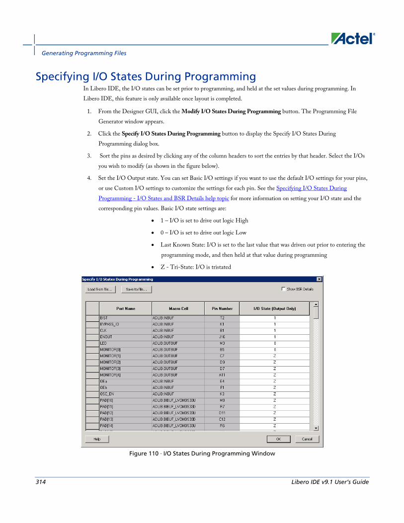
Generating Programming Files
314 Libero IDE v9.1 User’s Guide
Specifying I/O States During Programming In Libero IDE, the I/O states can be set prior to programming, and held at the set values during programming. In Libero IDE, this feature is only available once layout is completed.
1. From the Designer GUI, click the Modify I/O States During Programming button. The Programming File Generator window appears.
2. Click the Specify I/O States During Programming button to display the Specify I/O States During Programming dialog box.
3. Sort the pins as desired by clicking any of the column headers to sort the entries by that header. Select the I/Os you wish to modify (as shown in the figure below).
4. Set the I/O Output state. You can set Basic I/O settings if you want to use the default I/O settings for your pins, or use Custom I/O settings to customize the settings for each pin. See the Specifying I/O States During Programming - I/O States and BSR Details help topic for more information on setting your I/O state and the corresponding pin values. Basic I/O state settings are:
• 1 – I/O is set to drive out logic High
• 0 – I/O is set to drive out logic Low
• Last Known State: I/O is set to the last value that was driven out prior to entering the programming mode, and then held at that value during programming
• Z - Tri-State: I/O is tristated
Figure 110 · I/O States During Programming Window

Custom I/O Settings and Boundary Scan Registers
Libero IDE v9.1 User’s Guide 315
6. Click OK to return to the FlashPoint – Programming File Generator window.
Note: NOTE: I/O States During programming are saved to the ADB and resulting programming files after completing programming file generation.
Custom I/O Settings and Boundary Scan Registers Each I/O in your device is comprised of an Input, Output and Output Enable Boundary Scan Register (BSR) cell..
The BSR cells enable you to define I/O states during programming and control the individual states for each Input, Output, and Output Enable register.
The Specify I/O States During Programming dialog box enables access to each of these BSR cells for control over the individual states. You can use the I/O State (Output Only) settings to set a specific output state and ignore the other values for the individual BSR elements, or you can click the Show BSR Details checkbox for control over the settings for each Input, Output Enable, and Output as you exit programming.
Specifying I/O States During Programming - I/O States and BSR Details
The I/O States During Programming dialog box enables you to set custom I/O states prior to programming.
I/O State (Output Only) Sets your I/O states during programming to one of the values shown in the list below.
• 1 – I/Os are set to drive out logic High
• 0 – I/Os are set to drive out logic Low
• Last Known State: I/Os are set to the last value that was driven out prior to entering the programming mode, and then held at that value during programming
• Z - Tri-State: I/Os are tristated
When you set your I/O state, the Boundary Scan Register cells are set according to the table below. Use the Show BSR Details option to set custom states for each cell.
Table 11 · Default I/O Output Settings
Output State Settings
Input Control (Output Enable) Output
Z (Tri-State) 1 0 0
0 (Low) 1 1 0
1 (High) 0 1 1

Generating Programming Files
316 Libero IDE v9.1 User’s Guide
Output State Settings
Input Control (Output Enable) Output
Last_Known_State Last_Known_State Last_Known_State Last_Known_State
Table Key:
• 1 – High: I/Os are set to drive out logic High
• 0 – Low: I/Os are set to drive out logic Low
• Last_Known_State - I/Os are set to the last value that was driven out prior to entering the programming mode, and then held at that value during programming
Boundary Scan Registers - Enabled with Show BSR Details Sets your I/O state to a specific output value during programming AND enables you to customize the values for the Boundary Scan Register (Input, Output Enable, and Output). You can change any Don't Care value in Boundary Scan Register States without changing the Output State of the pin (as shown in the table below).
For example, if you want to Tri-State a pin during programming, set Output Enable to 0; the Don't Care indicates that the other two values are immaterial.
If you want a pin to drive a logic High and have a logic 1 stored in the Input Boundary scan cell during programming, you may set all the values to 1.
Table 12 · BSR Details I/O Output Settings
Output State Settings
Input Output Enable Output
Z (Tri-State) Don't Care 0 Don't Care
0 (Low) Don't Care 1 0
1 (High) Don't Care 1 1
Last Known State Last State Last State Last State
Table Key:
• 1 – High: I/Os are set to drive out logic High
• 0 – Low: I/Os are set to drive out logic Low
• Don't Care – Don’t Care values have no impact on the other settings.

Specify I/O States During Programming Dialog Box
Libero IDE v9.1 User’s Guide 317
• Last_Known_State – Sampled value: I/Os are set to the last value that was driven out prior to entering the programming mode, and then held at that value during programming
The figure below shows an example of Boundary Scan Register settings.
Figure 111 · Boundary Scan Registers
Specify I/O States During Programming Dialog Box The I/O States During Programming dialog box enables you to specify custom settings for I/Os in your programming file. This is useful if you want to set an I/O to drive out specific logic, or if you want to use a custom I/O state to manage settings for each Input, Output Enable, and Output associated with an I/O.
Load from file Load from file enables you to load an I/O Settings (*.ios) file. You can use the IOS file to import saved custom settings for all your I/Os. The exported IOS file have the following format:
• Used I/Os have an entry in the IOS file with the following format:
set_prog_io_state -portName {<design_port_name>} -input <value> -outputEnable <value> -output <value>
• Unused I/Os have an entry in the IOS file with the following format:
set_prog_io_state -pinNumber {<device_pinNumber>} -input <value> -outputEnable <value> -output <value>
Where <value> is:

Generating Programming Files
318 Libero IDE v9.1 User’s Guide
• 1 – I/O is set to drive out logic High
• 0 – I/O is set to drive out logic Low
• Last_Known_State: I/O is set to the last value that was driven out prior to entering the programming mode, and then held at that value during programming
• Z - Tri-State: I/O is tristated
Save to file Saves your I/O Settings File (*.ios) for future use. This is useful if you set custom states for your I/Os and want to use them again later in conjunction with a PDC file.
Port Name Lists the names of all the ports in your design.
Macro Cell Lists the I/O type, such as INBUF, OUTBUF, PLLs, etc.
Pin Number The package pin associate with the I/O.
I/O State (Output Only) Your custom I/O State set during programming. This heading changes to Boundary Scan Register if you select the BSR Details checkbox; see the Specifying I/O States During Programming - I/O States and BSR Details help topic for more information on the BSR Details option.

FlashLock®
Libero IDE v9.1 User’s Guide 319
Figure 112 · I/O States During Programming Dialog Box
FlashLock® Actel’s ProASIC and ProASICPLUS devices contain FlashLock circuitry to lock the device by disabling the programming and readback capabilities after programming. Care has been taken to make the locking circuitry very difficult to defeat through electronic or direct physical attack.
FlashLock has three security options: No Lock, Permanent Lock, and Keyed Lock.
No Lock Creates a programming file which does not secure your device.
Permanent Lock The permanent lock makes your device one time programmable. It cannot be unlocked by you or anyone else.
Keyed Lock Within each ProASIC and ProASICPLUS device, there is a multi-bit security key user key. The number of bits depends on the size of the device. The tables below show the key size of different ProASIC and ProASICPLUS devices, respectively. Once secured, read permission and write permission can only be enabled by providing the correct user key to first unlock the device. The maximum security key for the device is shown in the dialog box.
Table 13 · Key Size of ProASIC Devices
Device Key Size (bits) Key Size (hex)

Generating Programming Files
320 Libero IDE v9.1 User’s Guide
Device Key Size (bits) Key Size (hex)
A500K050 51 bits 13
A500K130 51 bits 13
A500K180 51 bits 13
A500K270 51 bits 13
Table 14 · Key Size of ProASICPLUS Devices
Device Key Size (bits) Key Size (hex)
APA075 79 bits 20
APA150 79 bits 20
APA300 79 bits 20
APA450 119 bits 30
APA600 167 bits 42
APA750 191 bits 48
APA1000 263 bits 66
Programming the Security Bit Two device programmers, Silicon Sculptor and Flash Pro, are available for ProASIC and ProASICPLUS devices. If the programming file contains the security key, by default the Silicon Sculptor and Flash Pro programming software automatically enables the "secure" option and programs the security key. You can turn this off, should you decide not to program using the security key.
Please refer to the application note “Implementation of Security in Actel's ProASIC and ProASICPLUS Flash-Based FPGAs” for more details.
Generating Bitstream and STAPL files Bitstream allows you to generate a STAPL file for IGLOO, ProASIC3, SmartFusion, Fusion, ProASICPLUS, and ProASIC devices, or a bitstream file for ProASIC and ProASICPLUS families. Please consult the Program Files table to find out which file type you should choose.

Generating a Fuse File
Libero IDE v9.1 User’s Guide 321
To generate a bitstream or STAPL file:
1. From the Tools menu, choose Programming File.
2. Select Bitstream or STAPL from the File Type drop-down list box. Bitstream files are not available for IGLOO, ProASIC3, SmartFusion and Fusion devices.
3. FlashLock. Select one of the following options:
• No Locking: Creates a programming file which does not secure your device.
• Use Keyed Lock: Creates a programming file which secures your device with a FlashLock key. The maximum security key for the device is shown in the dialog box. The maximum security key for the device is shown in the dialog box.
• Use Permanent Lock: Creates a one-time programmable device.
4. Click OK. Designer validates the security key and alerts you to any concerns.
Note: Note: The bitstream file header contains the security key.
Generating a Fuse File Fuse allows you to generate a programming file for your Actel antifuse devices. Fuse files work with Actel's Silicon Sculptor programmers. (For Axcelerator families, you must use the Silicon Sculptor II programmer.)
To generate a fuse programming file: 1. From the Tools menu, choose Programming File.
2. File Type. Select the appropriate file type in the File Type drop-down menu. Select AFM-APS2 if you are using Silicon Sculptor programmer.
3. Silicon Signature (Optional): Enter a 5 digit hexadecimal value in the Silicon Signature box to identify the design. Valid characters are 0 through 9, and a through f.
• Output filename: Designer automatically names the file based on the <design_name>.adb file. You can change the name by entering it in the File Name box. Click Browse to change the directory. Do not add a file extension or suffix to the file name. The Designer software automatically adds the extension to the programming file name when you specify the programming format.
• Generate Probe File Also: This option automatically generates a PRB file for use with Silicon Explorer.
• Disable clamping diode for unused I/O pins: (SX-A and eX families). Select box to disable clamping diode.
• Use the JTAG Reset Pull-up Resistor: (Axcelerator family) Select to enable pull-up resistors on the TRSTB pin (JTAG Reset pin which is active low). This is not part of the JTAG standard but can be useful if you want to make sure that the JTAG tap controller is not reset by mistake if the TRSTB pin is not connected. The pull-up resistor guarantees that if the pin is not driven to low (active), the pin is left in an inactive state (high).
• Use the Global Set Fuse: (Axcelerator family) Select to set flip-flops to a known state after power-up. If not selected all flip-flops are set to '0' at power up. If this option is used, all flip-flops are set to '1' at power up.

Generating Programming Files
322 Libero IDE v9.1 User’s Guide
2. Click OK when finished to save the file.
Generating Prototype Files When designing for RTAX-S, you can use the Axcelerator family for prototyping. Please refer to the application note Prototyping RTAX-S Using Axcelerator Devices for more information.
Note: Designer maps the pins from the RT package to the commercial prototyping vehicle.
To generate prototype files:
1. From the Designer Tools menu, choose Generate Prototype. This displays the Generate Prototype Files dialog box.
2. Set your Prototype Die/Package. The adapter socket required for prototyping varies depending on your target die/package.
For CQFB to FBGA, see the CQFB to FBGA Adapter Sockets application note.
For CCGA to FBGA, see the CCGA to FBGA Adapter Sockets application note.
3. Set your Silicon Signature (optional) - Enter a 5 digit hexadecimal value in the Silicon Signature box to identify the design. Valid characters are '0' through '9', and 'a' through 'f'.
4. Select your Output directory. Click the Browse button to navigate to a directory.
5. Set options:
• Generate probe file also - This option automatically generates a PRB file for use with Silicon Explorer
• Use the JTAG reset pull-up resistor - Select to enable pull-up resistors on the TRSTB pin (JTAG Reset pin which is active low). This is not part of the JTAG standard but can be useful if you want to make sure that the JTAG tap controller is not reset by mistake if the TRSTB pin is not connected. The pull-up resistor guarantees that if the pin is not driven to low (active), the pin is left in an inactive state (high).
• Use the Global Set Fuse - Select to set flip-flops to a known state after power-up. If not selected all flip-flops are set to '0' at power up. If this option is used, all flip-flops are set to '1' at power up.
6. Click OK. Designer runs through the process of creating the prototype files and generates the AFM for the selected die/package. After the prototype flow is complete, Designer automatically returns to the RT project. You must open your new prototyping ADB file manually to verify it.
Saving your design Once you have imported a netlist and compiled a design, you can save the design as an ADB file.
To save your design as an ADB file:
1. From the File menu, choose Save or click the save icon in the toolbar.
2. Enter the File name and click Save. The default file name is the name you previously entered in the setup dialog box. The default format is ADB. Make sure you save your file in ADB format.

Exiting Designer
Libero IDE v9.1 User’s Guide 323
Once you have saved your compiled design as an ADB file, during any future Designer sessions, you can open the ADB file, skipping the compile step, and perform optimization on the design, including updating netlist and auxiliary file information.
Exiting Designer To end a Designer session, from the File menu, select Exit.
If the information has not been saved to disk, you are asked if your want to save the design before exiting. If you choose YES, the <design_name>.adb file is updated with information entered the current session. If you choose NO, the informations is not saved and the <design_name>.adb file remains unchanged.

TCL Command Reference
324 Libero IDE v9.1 User’s Guide
TCL Command Reference
Basic syntax
Libero IDE v9.1 User’s Guide 325
Introduction to Tcl Scripting Tcl, the Tool Command Language, pronounced tickle, is an easy-to-learn scripting language that is compatible with Libero IDE and Designer software. You can run scripts from either the Windows or UNIX command line or store and run a series of commands in a *.tcl batch file.
This section provides a quick overview of the main features of Tcl:
• Basic syntax
• Types of Tcl commands
• Variables
• Command substitution
• Quotes and braces
• Lists and arrays
• Control structures
• Handling exceptions
• Print statement and Return values
• Running Tcl scripts from the command line
• Running Tcl scripts from the GUI
• Exporting Tcl scripts
• Extended_run_gui
• Extended_run_shell
• Sample Tcl scripts
• Project Manager Tcl Commands
• Designer Tcl Commands
For complete information on Tcl scripting, refer to one of the books available on this subject. You can also find information about Tcl at web sites such as http://www.tcl.tk.
Basic syntax Tcl scripts contain one or more commands separated by either new lines or semicolons. A Tcl command consists of the name of the command followed by one or more arguments. The format of a Tcl command is:
command arg1 ... argN
The command in the following example computes the sum of 2 plus 2 and returns the result, 4.
expr 2 + 2
The expr command handles its arguments as an arithmetic expression, computing and returning the result as a string. All Tcl commands return results. If a command has no result to return, it returns an empty string.

TCL Command Reference
326 Libero IDE v9.1 User’s Guide
To continue a command on another line, enter a backslash (\) character at the end of the line. For example, the following Tcl command appears on two lines:
import -format "edif" -netlist_naming "Generic" -edif_flavor "GENERIC" {prepi.edn}
Comments must be preceded by a hash character (#). The comment delimiter (#) must be the first character on a line or the first character following a semicolon, which also indicates the start of a new line. To create a multi-line comment, you must put a hash character (#) at the beginning of each line.
Note: Note: Be sure that the previous line does not end with a continuation character (\). Otherwise, the comment line following it will be ignored.
Special characters Square brackets ([ ]) are special characters in Tcl. To use square brackets in names such as port names, you must either enclose the entire port name in curly braces, for example, pin_assign -port {LFSR_OUT[15]} -iostd lvttl -slew High, or lead the square brackets with a slash (\) character as shown in the following example: pin_assign -port LFSR_OUT\[15\] -iostd lvttl -slew High
Sample Tcl script #Set up a new design
new_design -name "multiclk" -family "Axcelerator" -path {.}
# Set device, package, speed grade, default I/O standard and
# operating conditions
set_device -die "AX1000" -package "BG729" -speed "-3" \
-voltage "1.5" -iostd "LVTTL" -temprange "COM" -voltrange "COM"
# Import the netlist
import -format "verilog" {multiclk.v}
# Compile the netlist
compile
# Import a PDC file
import_aux -format "pdc" {multiclk.pdc}
# Run standard layout
layout -incremental "OFF"
# Generate backannotated sdf and netlist file
backannotate -name {multiclk_ba} -format "sdf" -language "Verilog"
# Generate timing report
report -type "timing" -sortby "actual" -maxpaths "100" {report_timing.txt}
# Generate programming file

Types of Tcl commands
Libero IDE v9.1 User’s Guide 327
export -format "AFM" -signature "ffff" {multiclk.afm}
Types of Tcl commands There are three types of Tcl commands:
• Built-in commands
• Procedures created with the proc command
• Commands built into the Designer software
Built-in commands Built-in commands are provided by the Tcl interpreter. They are available in all Tcl applications. Here are some examples of built-in Tcl commands:
• Tcl provides several commands for manipulating file names, reading and writing file attributes, copying files, deleting files, creating directories, and so on.
• exec - run an external program. Its return value is the output (on stdout) from the program, for example:
set tmp [ exec myprog ]
puts stdout $tmp
• You can easily create collections of values (lists) and manipulate them in a variety of ways.
• You can create arrays - structured values consisting of name-value pairs with arbitrary string values for the names and values.
• You can manipulate the time and date variables.
• You can write scripts that can wait for certain events to occur, such as an elapsed time or the availability of input data on a network socket.
Procedures created with the proc command You use the proc command to declare a procedure. You can then use the name of the procedure as a Tcl command.
The following sample script consists of a single command named proc. The proc command takes three arguments:
• The name of a procedure (myproc)
• A list of argument names (arg1 arg2)
• The body of the procedure, which is a Tcl script
proc myproc { arg1 arg2 } {
# procedure body
}
myproc a b
TCL Command Reference
328 Libero IDE v9.1 User’s Guide
Commands built into the Designer software Many functions that you can perform through the Designer software's GUI interface, you can also perform using an equivalent Tcl command. For example, the backannotate command is equivalent to executing the Back-Annotate command from Designer's Tools menu. For a list of Tcl commands supported in the Designer software, see "Tcl Commands."
Variables With Tcl scripting, you can store a value in a variable for later use. You use the set command to assign variables.For example, the following set command creates a variable named x and sets its initial value to 10.
set x 10
A variable can be a letter, a digit, an underscore, or any combination of letters, digits, and underscore characters. All variable values are stored as strings.
In the Tcl language, you do not declare variables or their types. Any variable can hold any value. Use the dollar sign ($) to obtain the value of a variable, for example:
set a 1
set b $a
set cmd expr
set x 11
$cmd $x*$x
The dollar sign $ tells Tcl to handle the letters and digits following it as a variable name and to substitute the variable name with its value.
Global Variables Variables can be declared global in scope using the Tcl global command. All procedures, including the declaration can access and modify global variables, for example:
global myvar
Command substitution By using square brackets ([]), you can substitute the result of one command as an argument to a subsequent command, as shown in the following example:
set a 12
set b [expr $a*4]
Tcl handles everything between square brackets as a nested Tcl command. Tcl evaluates the nested command and substitutes its result in place of the bracketed text. In the example above, the argument that appears in square brackets in the second set command is equal to 48 (that is, 12* 4 = 48).
Conceptually,
set b [expr $a * 4]
expands to
Quotes and braces
Libero IDE v9.1 User’s Guide 329
set b [expr 12 * 4 ]
and then to
set b 48
Quotes and braces The distinction between braces ({ }) and quotes (" ") is significant when the list contains references to variables. When references are enclosed in quotes, they are substituted with values. However, when references are enclosed in braces, they are not substituted with values.
Example
With Braces With Double Quotes
set b 2 set b 2
set t { 1 $b 3 } set t " 1 $b 3 "
set s { [ expr $b + $b ] } set s " [ expr $b + $b ] "
puts stdout $t puts stdout $t
puts stdout $s puts stdout $s
will output
1 $b 3 vs. 1 2 3 [ expr $b + $b ] 4
Filenames In Tcl syntax, filenames should be enclosed in braces { } to avoid backslash substitution and white space separation. Backslashes are used to separate folder names in Windows-based filenames. The problem is that sequences of “\n” or “\t” are interpreted specially. Using the braces disables this special interpretation and specifies that the Tcl interpreter handle the enclosed string literally. Alternatively, double-backslash “\\n” and “\\t” would work as well as forward slash directory separators “/n” and “/t”.For example, to specify a file on your Windows PC at c:\newfiles\thisfile.adb, use one of the following:
{C:\newfiles\thisfile.adb}
C:\\newfiles\\thisfile.adb
"C:\\newfiles\\thisfile.adb"
C:/newfiles/thisfile.adb
"C:/newfiles/thisfile.adb"
If there is white space in the filename path, you must use either the braces or double-quotes. For example:
C:\program data\thisfile.adb
should be referenced in Tcl script as
TCL Command Reference
330 Libero IDE v9.1 User’s Guide
{C:\program data\thisfile.adb} or "C:\\program data\\thisfile.adb"
If you are using variables, you cannot use braces { } because, by default, the braces turn off all special interpretation, including the dollar sign character. Instead, use either double-backslashes or forward slashes with double quotes. For example:
"$design_name.adb"
Note: Note: To use a name with special characters such as square brackets [ ], you must put the entire name between curly braces { } or put a slash character \ immediately before each square bracket.
The following example shows a port name enclosed with curly braces:
pin_assign -port {LFSR_OUT[15]} -iostd lvttl -slew High
The next example shows each square bracket preceded by a slash:
pin_assign -port LFSR_OUT\[15\] -iostd lvttl -slew High
Lists and arrays A list is a way to group data and handle the group as a single entity. To define a list, use curly braces { } and double quotes “ “. For example, the following set command {1 2 3 }, when followed by the list command, creates a list stored in the variable "a." This list will contain the items "1," "2," and "3."
set a { 1 2 3 }
Here's another example:
set e 2
set f 3
set a [ list b c d [ expr $e + $f ] ]
puts $a
displays (or outputs):
b c d 5
Tcl supports many other list-related commands such as lindex, linsert, llength, lrange, and lappend. For more information, refer to one of the books or web sites available on this subject.
Arrays An array is another way to group data. Arrays are collections of items stored in variables. Each item has a unique address that you use to access it. You do not need to declare them nor specify their size.
Array elements are handled in the same way as other Tcl variables. You create them with the set command, and you can use the dollar sign ($) for their values.
set myarray(0) "Zero"
set myarray(1) "One"
set myarray(2) "Two"
for {set i 0} {$i < 3} {incr i 1} {
Output:
Zero
One

Control structures
Libero IDE v9.1 User’s Guide 331
Two
In the example above, an array called "myarray" is created by the set statement that assigns a value to its first element. The for-loop statement prints out the value stored in each element of the array.
Special arguments (command-line parameters) You can determine the name of the Tcl script file while executing the Tcl script by referring to the $argv0 variable.
puts “Executing file $argv0”
To access other arguments from the command line, you can use the lindex command and the argv variable:
To read the the Tcl file name:
lindex $argv 0
To read the first passed argument:
lindex $argv 1
Example
puts "Script name is $argv0" ; # accessing the scriptname
puts "first argument is [lindex $argv 0]"
puts "second argument is [lindex $argv 1]"
puts "third argument is [lindex $argv 2]"
puts "number of argument is [llength $argv]"
set des_name [lindex $argv 0]
puts "Design name is $des_name"
Control structures Tcl control structures are commands that change the flow of execution through a script. These control structures include commands for conditional execution (if-then-elseif-else) and looping (while, for, catch).
An "if" statement only executes the body of the statement (enclosed between curly braces) if the Boolean condition is found to be true.
if/else statements if { “$name” == “paul” } then {
…
# body if name is paul
} elseif { $code == 0 } then {
…
# body if name is not paul and if value of variable code is zero
} else {
…
# body if above conditions is not true
}
for loop statement A "for" statement will repeatedly execute the body of the code as long as the index is within a specified limit.

TCL Command Reference
332 Libero IDE v9.1 User’s Guide
for { set i 0 } { $i < 5 } { incr i } {
…
# body here
}
while loop statement A "while" statement will repeatedly execute the body of the code (enclosed between the curly braces) as long as the Boolean condition is found to be true.
while { $p > 0 } {
…
}
catch statement A "catch" statement suspends normal error handling on the enclosed Tcl command. If a variable name is also used, then the return value of the enclosed Tcl command is stored in the variable.
catch { open “$inputFile” r } myresult
Handling exceptions (Tcl scripting) To control the flow of the Designer software based on certain conditions (for example, success or failure of certain commands), you can use the Tcl built-in catch command as follows:
if { [ catch {open_design $des_name.adb} ] } {
puts "Cannot open $des_name.adb"
export -format "log" -diagnostic $des_name.log"
exit 1
} else {
puts "Design $des_name.adb Successfully Opened"
}
## set layout mode to standard
layout -incremental "OFF"
if { [ catch {layout} ] } {
puts "Layout Failed"
export -format "log" -diagnostic $des_name.log"
exit 1
} else {
puts "layout successful"
export -format log "$des_name.log"
save_design "$des_name.adb";
close_design
}

Print statement and Return values
Libero IDE v9.1 User’s Guide 333
Print statement and Return values
Print Statement Use the puts command to write a string to an output channel. Predefined output channels are “stdout” and “stderr.” If you do not specify a channel, then puts display text to the stdout channel.
Note: Note: The STDIN Tcl command is not supported by Actel tools.
Example:
set a [ myprog arg1 arg2 ]
puts "the answer from myprog was $a (this text is on stdout)"
puts stdout “this text also is on stdout”
Return Values The return code of a Tcl command is a string. You can use a return value as an argument to another function by enclosing the command with square brackets [ ].
Example:
set a [ prog arg1 arg2 ]
exec $a
The Tcl command “exec” will run an external program. The return value of “exec” is the output (on stdout) from the program.
Example:
set tmp [ exec myprog ]
puts stdout $tmp
Running Tcl scripts from the GUI Instead of running scripts from the command line, you can use Execute Script dialog box to run a script in the Project Manager or Designer.
To run a Tcl script from the GUI:
1. In Project Manager, from the Project menu choose Execute Script. In Designer, from the File menu choose Execute Script. This opens the Execute Script dialog box (as shown in the figure below).

TCL Command Reference
334 Libero IDE v9.1 User’s Guide
Figure 113 · Execute Script Dialog Box
2. Click Browse to display the Open dialog box, in which you can navigate to the folder containing the script file to open. When you click Open, Designer enters the full path and script filename into the Execute Script dialog box for you.
3. In the Arguments edit box, enter the arguments to pass to your Tcl script as shown in the following sample Execute Script dialog box. Separate each argument by a space character. For information about accessing arguments passed to a Tcl script, see "Running Scripts from the command line."
Figure 114 · Execute Script Dialog Box Example
4. Click Run.
Specify your arguments in the Execute Script dialog box. To get those argument values from your Tcl script, use the following:
puts "Script name: $argv0"
puts "Number of arguments: $argc"
set i 0
foreach arg $argv {
puts "Arg $i : $arg"
incr i
}

Running Tcl scripts from the command line
Libero IDE v9.1 User’s Guide 335
Running Tcl scripts from the command line You can run Tcl scripts from your Windows or Unix command line as well as pass arguments to scripts from the command line.
To execute a Tcl script file in the Libero IDE Project Manager software from a shell command line:
At the prompt, type the path to the Actel software followed by the word "SCRIPT" and a colon, and then the name of the script file as follows:
<location of Actel software>\bin\libero SCRIPT:<filename>
where <location of Actel software> is the root directory in which you installed the Actel software,
and <filename> is the name, including a relative or full path, of the Tcl script file to execute. For
example, to run the Tcl script file "myscript.tcl", type: C:\libero\designer\bin\libero SCRIPT:myscript.tcl
If myscript.tcl is in a particular folder named "mydesign", you can use SCRIPT_DIR to change the current working directory before calling the script, as in the following example:
C:\libero\designer\bin\libero SCRIPT:myscript.tcl "SCRIPT_DIR:C:\actelprj\mydesign"
To execute a Tcl script file in the Designer software from a shell command line:
At the prompt, type the path to the Actel software followed by the word "SCRIPT" and a colon, and then the name of the script file as follows:
<location of Actel software>\bin\designer SCRIPT:<filename>
where <location of Actel software> is the root directory in which you installed the Actel software, and<filename>is the name, including a relative or full path, of the Tcl script file to execute. For example, to run the Tcl script file named "myscript.tcl" from the command line, you can type:
C:\libero\designer\bin\designer SCRIPT:myscript.tcl
If myscript.tcl is in a particular folder named "mydesign", you can use SCRIPT_DIR to change the current working directory before calling the script, as in the following example:
C:\libero\designer\bin\designer SCRIPT:myscript.tcl "SCRIPT_DIR:C:\actelprj\mydesign"
To pass arguments from the command line to your Tcl script file:
At the prompt, type the path to the Actel software followed by the SCRIPT argument. Enclose the entire argument expression in double quotes:
<location of Actel software>\bin\designer "SCRIPT:<filename arg1 arg2 ...>"
where <location of Actel software> is the root directory in which you installed the Actel software, and <filename arg1 arg2 ...>is the name, including a relative or full path, of the Tcl script file and arguments you are passing to the script file.
For example,
C:\libero\designer\bin\designer "SCRIPT:myscript.tcl one two three"
To obtain the output from the log file:
At the prompt, type the path to the Actel software followed by the SCRIPT and LOGFILE arguments.
<location of Actel software>\bin\designer "SCRIPT:<filename arg1 arg2 ...>" LOGFILE:<output.log>

TCL Command Reference
336 Libero IDE v9.1 User’s Guide
where <location of Actel software> is the root directory in which you installed the Actel software, <filename arg1 arg2 ...>is the name, including a relative or full path, of the Tcl script file and arguments you are passing to the script file, and output.log is the name of the log file.
For example,
C:\libero\designer\bin\designer "SCRIPT:myscript.tcl one two three" "LOGILE:output.log"
Exporting Tcl scripts You can write out a Tcl script file that contains the commands executed in the current session. You can then use this exported Tcl script to re-execute the same commands interactively or in batch. You can also use this exported script to become more familiar with Tcl syntax.
You can export Tcl scripts from the Project Manager or Designer; the actions are the same.
To export a Tcl session script from the Project Manager or Designer:
1. From the File menu, choose Export>Script Files. The Export Script Files dialog box appears.
2. From the Save in drop-down menu, navigate to the folder in which you want to save the script files.
3. Type a filename for this Tcl script file.
4. Click Save. The Script Export Options dialog box appears
Figure 115 · Script Export Options
5. Check the Include Commands from Current Design [Project] Only checkbox. This option applies only if you opened more than one design or project in your current session. If so, and you do not check this box, Project Manager / Designer exports all commands from your current session.
6. Select the radio button for the appropriate filename formatting. To export filenames relative to the current working directory, select Relative filenames (default) formatting. To export filenames that include a fully specified path, select Qualified filenames (full path; including directory name) formatting.

extended_run_gui - Designer Only
Libero IDE v9.1 User’s Guide 337
Choose Relative filenames if you do not intend to move the Tcl script from the saved location, or Qualified filenames if you plan to move the Tcl script to another directory or machine.
7. Click OK.
Project Manager / Designer saves the Tcl script with the specified filename.
Note: Notes:
• When exporting Tcl scripts, Project Manager and Designer always encloses filenames in curly braces to ensure portability.
• Project Manager and Designer software do not write out any Tcl variables or flow-control statements to the exported Tcl file, even if you had executed the design commands using your own Tcl script. The exported Tcl file only contains the tool commands and their accompanying arguments.
extended_run_gui - Designer Only This script is used to reproduce the GUI behavior and is more suited for running through Designer or inside another Designer TCL script.
The only difference from the extended_run_shell Tcl script is that the extended_run_gui.tcl script does not need the –adb argument and assumes that the design is already saved and open.
extended_run_gui.tcl [-n numPasses] [-starting_seed_index numIndex] [-save_all] [-compare_criteria value] [-c clockName] [-analysis value] [-slack_criteria value] [-timing_driven|-standard] [-stop_on_success] [-run_placer value] [-place_incremental value] [-route_incremental value] [-effort_level numLevel] [-timing_weight numWeight] [-placer_high_effort value] [-mindel_repair value] [-power_driven value]
To invoke extended_run_gui from Designer:
1. Open an *.adb file in Designer.
2. From the File menu, select Execute Script. This opens the Execute Script dialog box.
Figure 116 · Execute Script Dialog Box

TCL Command Reference
338 Libero IDE v9.1 User’s Guide
3. Find the extended_run-gui.tcl script under ACTEL_SW_DIR/scripts and then copy all the parameters in to the arguments section.
4. Click Run.
To invoke extended_run_gui from within a TCL script:
1. Save the design in compiled state.
…
compile
save_design “my.adb”
2. Override the original argument list in the caller script and then source the extended_run_gui.tcl script.
set save_argv0 $::argv0
set save_argv $::argv
set ACTEL_SW_DIR $env(ACTEL_SW_DIR)
set ::argv0 “$ACTEL_SW_DIR/scripts/extended_run_gui.tcl”
set ::argv [list -n 3 -save_all -c PCI_CLK]
set ::argc [llength $::argv]
source $::argv0
set ::argv0 $save_argv0
set ::argv $save_argv
set ::argc [llength $::argv]
See Also Running Layout
Multiple Pass Layout
extended_run_shell
extended_run_shell - Designer Only Note: Note: This is not a Tcl command; it is a shell script that can be run from the command line. To invoke multiple
pass layout within another Designer Tcl script, refer to extended_run_gui.
The extended_run_shell Tcl script enables you to run the multiple pass layout in batch mode from a command line. Use this script from the tcl shell "acttclsh". This is the script or command-line equivalent to using the multiple pass layout in the GUI.
$ACTEL_SW_DIR/bin/acttclsh extended_run_shell.tcl -adb adbFileName.adb [-n numPasses] [-starting_seed_index numIndex] [-save_all] [-compare_criteria value] [-c clockName] [-analysis value] [-slack_criteria value] [-timing_driven|-standard] [-stop_on_success] [-run_placer value] [-place_incremental value] [-route_incremental value] [-effort_level numLevel] [-timing_weight numWeight] [-placer_high_effort value] [-mindel_repair value] [-power_driven value]

extended_run_shell - Designer Only
Libero IDE v9.1 User’s Guide 339
Arguments -adb adbFileName.adb
This is the design file to run multiple passes of layout. [-n numPasses]
Sets the number of passes to run. The default number of passes is 5. [-starting_seed_index numIndex]
Indicates the specific index into the array of random seeds which is to be the starting point for the passes. Its value should range from 1 to 101. If not specified, the default behavior is to continue from the last seed index which was used. [-save_all]
Saves all intermediate designs in<adbFileName>_r<runNum>_s<seedIndex>.adb. The best result is also stored to the original *.adb file as well. The default behavior does not save all results. [-compare_criteria value]
The following table shows the acceptable values for this argument:
Value Description
frequency Sets the criteria for comparing results between passes to be clock frequency based. This is the default. This option enables the -c option (described below).
violations Sets the criteria for comparing results between passes to be timing violations (slack) based. This option enables the -analysis, -slack_criteria, and -stop_on_success options (described below).
power Sets the criteria for comparing results between passes to be based on the lowest total power.
[-c clockName]
Applies only when the clock frequency comparison criteria is used. Specifies the particular clock that is to be examined. If no clock is specified, then the slowest clock frequency in the design in a given pass is used. [-analysis value]
Applies only when the timing violations comparison criteria is used. The following table shows the acceptable values for this argument:
Value Description
max Examines timing violations (slacks) obtained from maximum delay analysis. This is the default.
min Examines timing violations (slacks) obtained from minimum delay analysis.
[-slack_criteria value]
Applies only when the timing violations comparison criteria is used. The type of timing violations (slacks) is determined by the -analysis option. The following table shows the acceptable values for this argument:

TCL Command Reference
340 Libero IDE v9.1 User’s Guide
Value Description
worst Sets the timing violations criteria to worst slack. For each pass obtains the most amount of negative slack (or least amount of positive slack if all constraints are met) from the timing violations report. The largest value out of all passes will determine the best pass. This is the default.
tns Sets the timing violations criteria to total negative slack. For each pass obtains the sum of negative slacks from the first 100 paths from the timing violations report. The largest value out of all passes will determine the best pass. If no negative slacks exist for a pass, then the worst slack is used to evaluate that pass
[-stop_on_success]
Applies only when the timing violations comparison criteria is used. The type of timing violations (slacks) is determined by the -analysis option. Stops performing remaining passes if all timing constraints have been met (when there are no negative slacks reported in the timing violations report). [-timing_driven|-standard]
Sets layout mode to be timing driven or standard (non-timing driven). The default is -timing_driven or the mode used in the previous layout command. [-run_placer value]
The following table shows the acceptable values for this argument:
Value Description
on Invokes placer. This is the default.
off Skips placer.
[-place_incremental value]
The following table shows the acceptable values for this argument:
Value Description
off Discards previous placement. This is the default.
on Sets the previous placement as the initial starting point for each pass.
fix Locks previous placement for each pass.
[-route_incremental value]
The following table shows the acceptable values for this argument:
Value Description

extended_run_shell - Designer Only
Libero IDE v9.1 User’s Guide 341
Value Description
off Discards previous routing. This is the default.
on Sets the previous routing as the initial starting point for each pass.
[-effort_level numLevel]
This is an advanced option that is available only for Axcelerator, SX-A, and eX. It specifies the placement effort level. [-timing_weight numWeight]
This is an advanced option that is available only for ProASICPLUS, ProASIC, SX-A, and eX. It specifies the layout timing weight. [-placer_high_effort value]
This is an advanced option that is available only for IGLOO, ProASIC3, SmartFusion and Fusion families. The following table shows the acceptable values for this argument:
Value Description
off Runs layout in regular effort. This is the default.
on Activates high effort layout mode.
[-mindel_repair value]
This is an advanced option that is available only for IGLOO, ProASIC3, SmartFusion and Fusion families. The following table shows the acceptable values for this argument:
Value Description
off Does not run minimum delay violations repair. This is the default.
on Enables repair of minimum delay violations during route.
[-power_driven value]
This option is available only for IGLOO, ProASIC3, SmartFusion, Fusion, and Axceleratorfamilies. The following table shows the acceptable values for this argument:
Value Description
off Does not run power-driven layout. This is the default.
on Enables power-driven layout.

TCL Command Reference
342 Libero IDE v9.1 User’s Guide
Return A non-zero value will be returned on error.
Supported Families IGLOO, ProASIC3, SmartFusion, Fusion, ProASICPLUS, ProASIC, Axcelerator, eX, and SX-A
Exceptions None
Example 1. On my.adb, run 5 (default) passes continuing from the last seed index using slowest clock frequency (default)
comparison criteria. % acttclsh extended_run_shell.tcl -adb my.adb
2. On my.adb, run 3 passes starting with seed index 6, saving all results, using clock frequency comparison criteria for clock "PCI_CLK". % acttclsh extended_run_shell.tcl -adb my.adb -n 3 -starting_seed_index 6 -save_all -c PCI_CLK
3. On my.adb, run 5 (default) passes continuing from the last seed index, saving all results, using timing violations comparison criteria with maximum delay (default) analysis and worst slack (default) criteria; invoke high effort layout. % acttclsh extended_run_shell.tcl -adb my.adb -save_all -compare_criteria violations –placer_high_effort on
4. On my.adb, run 5 (default) passes continuing from the last seed index, saving all results, using timing violations comparison criteria with maximum delay (default) analysis and total negative slack criteria; invoke placement effort level 5. % acttclsh extended_run_shell.tcl -adb my.adb -save_all -compare_criteria violations -slack_criteria tns –effort_level 5
5. On my.adb, run 5 (default) passes continuing from the last seed index, saving all results, using timing violations comparison criteria with minimum delay analysis and worst slack (default) criteria; stop if there are no violations. % acttclsh extended_run_shell.tcl -adb my.adb -save_all -compare_criteria violations -analysis min –stop_on_success
6. On my.adb, run 5 (default) passes continuing from the last seed index, saving all results, using timing violations comparison criteria with minimum delay analysis and total negative slack criteria; invoke repair of minimum delay violations. % acttclsh extended_run_shell.tcl -adb my.adb -save_all -compare_criteria violations -analysis min -slack_criteria tns –mindel_repair on
See Also Running Layout
Multiple Pass Layout
extended_run_gui
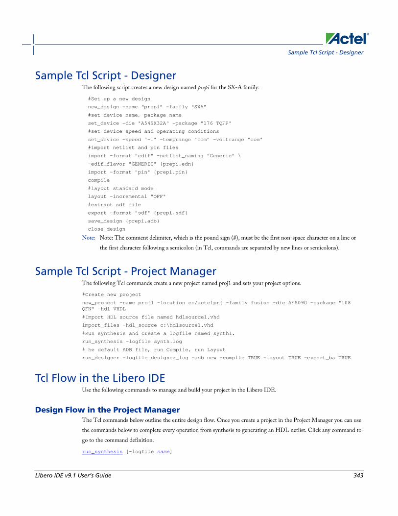
Sample Tcl Script - Designer
Libero IDE v9.1 User’s Guide 343
Sample Tcl Script - Designer The following script creates a new design named prepi for the SX-A family:
#Set up a new design
new_design -name “prepi” -family “SXA”
#set device name, package name
set_device -die "A54SX32A" -package "176 TQFP"
#set device speed and operating conditions
set_device -speed "-1" -temprange "com" -voltrange "com"
#import netlist and pin files
import -format "edif" -netlist_naming "Generic" \
-edif_flavor "GENERIC" {prepi.edn}
import -format "pin" {prepi.pin}
compile
#layout standard mode
layout -incremental "OFF"
#extract sdf file
export -format "sdf" {prepi.sdf}
save_design {prepi.adb}
close_design
Note: Note: The comment delimiter, which is the pound sign (#), must be the first non-space character on a line or the first character following a semicolon (in Tcl, commands are separated by new lines or semicolons).
Sample Tcl Script - Project Manager The following Tcl commands create a new project named proj1 and sets your project options.
#Create new project
new_project -name proj1 -location c:/actelprj -family fusion –die AFS090 -package "108 QFN" -hdl VHDL
#Import HDL source file named hdlsource1.vhd
import_files -hdl_source c:\hdlsource1.vhd
#Run synthesis and create a logfile named synth1.
run_synthesis -logfile synth.log
# he default ADB file, run Compile, run Layout
run_designer -logfile designer_log -adb new -compile TRUE -layout TRUE -export_ba TRUE
Tcl Flow in the Libero IDE Use the following commands to manage and build your project in the Libero IDE.
Design Flow in the Project Manager The Tcl commands below outline the entire design flow. Once you create a project in the Project Manager you can use the commands below to complete every operation from synthesis to generating an HDL netlist. Click any command to go to the command definition.
run_synthesis [-logfile name]

TCL Command Reference
344 Libero IDE v9.1 User’s Guide
run_simulation [-logfile name]
check_hdl -file filename
check_schematic -file filename
create_symbol [-module module]
export_io_constraints_from_adb -adb filename -output outputfilename
generate_ba_files -adb filename
generate_hdl_from_schematic [-module modulename]
generate_hdl_netlist [-netlist filename] [-run_drc "TRUE | FALSE"]
rollback_constraints_from_adb -adb filename -output output_filename
run_designer [-logfile filename] [-script "script to append"] [-append_commands "commands to execute"] [-adb "new | open | default"] [-compile "TRUE | FALSE"] [-layout "TRUE | FALSE"] [-export_ba "TRUE | FALSE"]
run_drc [-netlist file] [-gen_hdl "TRUE | FALSE"]
Manage Profiles in the Project Manager add_profile -name profilename -type "synthesis | simulation | stimulus | flashpro | physynth | coreconfig" -tool profiletool -location tool_location [-args tool_parameters] [-batch "TRUE | FALSE"]
edit_profile -name profilename -type "synthesis | simulation | stimulus | flashpro | physynth | coreconfig" -tool profiletool -location tool_location [-args tool_parameters] [-batch "TRUE | FALSE"] [-new_name name]
export_profiles -file name [-export "predefined | user | all"]
remove_profile -name profile_name
select_profile -name profile_name
Linking Files change_link_source -file filename -path pathname
create_links [-hdl_source file]* [-stimulus file]* [-sdc file]* [-pin file]* [-dcf file]* [-gcf file]* [-pdc file]* [-crt file]* [-vcd file]*
export_as_link -file filename -path link_path
unlink -file file [-local local_filename]
Set Simulation Options in the Project Manager add_modelsim_path -lib library_name [-path library_path] [-remove " "]
Set Device in the Project Manager set_device [-family family] [-die die] [-package package]
Miscellaneous Operations in the Project Manager project_settings [-hdl "VHDL | VERILOG"] [-auto_update_modelsim_ini "TRUE | FALSE"] [-auto_update_viewdraw_ini "TRUE | FALSE"] [-block_mode "TRUE | FALSE"] [-

Project Manager Tcl Command Reference
Libero IDE v9.1 User’s Guide 345
auto_generate_synth_hdl "TRUE | FALSE"] [-auto_generate_physynth_hdl "TRUE | FALSE"] [-auto_run_drc "TRUE | FALSE"] [-auto_generate_viewdraw_hdl "TRUE | FALSE"] [-auto_file_detection "TRUE | FALSE"]
refresh
set_option [-synth "TRUE | FALSE"] [-physynth "TRUE | FALSE"] [-module "module"]
remove_core -name core_name
Project Manager Tcl Command Reference A Tcl (Tool Command Language) file contains scripts for simple or complex tasks. You can run scripts from either the Windows or UNIX command line or store and run a series of Tcl commands in a *.tcl batch file. You can also run scripts from within the GUI in Project Manager.
Note: Note: Tcl commands are case sensitive. However, their arguments are not.
The Libero IDE Project Manager supports the following Tcl scripting commands:
Command Action
add_file_to_library Adds a file to a library in your project
add_library Adds a VHDL library to your project
add_modelsim_path Adds a ModelSim simulation library to your project
add_profile Adds a profile; sets the same values as the Add or Edit Profile dialog box
associate_stimulus Associates a stimulus file in your project
change_link_source Changes the source of a linked file in your project
check_hdl Checks the HDL in the specified file
check_schematic Checks the schematic
close_project Closes the current project in Libero IDE
create_links Creates a link (or links) to a file/files in your project
create_symbol Creates a symbol in a module
delete_files Deletes files from your Libero IDE project
edit_profile Edits a profile; sets the same values as the Add or Edit Profile dialog box

TCL Command Reference
346 Libero IDE v9.1 User’s Guide
Command Action
export_as_link Exports a file to another directory and links to the file
export_io_constraints_from_adb Exports the I/O constraints from your project ADB file to an output file
export_profiles Exports your tool profiles; performs the same action as the Export Profiles dialog box
generate_ba_files Generates the back-annotate files for your design
generate_hdl_from_schematic Generates an HDL file from your schematic
generate_hdl_netlist Generates the HDL netlist for your design and runs the design rule check
import_files (Libero IDE) Imports files into your Libero IDE project
new_project Creates a new project in the Libero IDE
open_project Opens an existing Libero IDE project
organize_cdbs Organizes the CDB files in your project
organize_constraints Organizes the constraint files in your project
organize_sources Organizes the source files in your project
project_settings Modifies project flow settings for your Libero IDE project
remove_core Removes a core from your project
remove_library Removes a VHDL library from your project
remove_profile Deletes a tool profile
rename_library Renames a VHDL library in your project
rollback_constraints_from_adb Opens the ADB file, exports the PDC file, and then replaces it with the specified PDC file
run_designer Runs Designer with compile and layout options (if selected)

Project Manager Tcl Command Reference
Libero IDE v9.1 User’s Guide 347
Command Action
run_drc Runs the design rule check on your netlist and generates an HDL file
run_simulation Runs simulation on your project with your default simulation tool and creates a logfile
run_synthesis Runs synthesis on your project and creates a logfile
save_log Saves your Libero IDE log file
save_project Saves your project
save_project_as Saves your project with a different name
select_profile Selects a profile to use in your project
set_actel_lib_options Sets your simulation library to default, or to another library
set_device (Project Manager) Sets your device family, die, and package in the Project Manager
set_modelsim_options Sets your ModelSim simulation options
set_option Sets your synthesis options on a module
set_userlib_options Sets your user library options during simulation
set_root Sets the module you specify as the root
synplify Runs Synplify in batch mode and executes a Tcl script.
synplify_pro Runs Synplify Pro in batch mode and executes a Tcl script.
unlink Removes a link to a file in your project
use_file Specifies which file in your project to use
use_source_file Defines a module for your project

TCL Command Reference
348 Libero IDE v9.1 User’s Guide
Tcl command documentation conventions The following table shows the typographical conventions used for the Tcl command syntax.
Syntax Notation Description
command -argument
Commands and arguments appear in Courier New typeface.
variable Variables appear in blue, italic Courier New typeface. You must substitute an appropriate value for the variable.
[-argumentvalue] [variable]+
Optional arguments begin and end with a square bracket with one exception: if the square bracket is followed by a plus sign (+), then users must specify at least one argument. The plus sign (+) indicates that items within the square brackets can be repeated. Do not enter the plus sign character.
Note: Note: All Tcl commands are case sensitive. However, their arguments are not.
Examples Syntax for the get_defvar command followed by a sample command:
get_defvar variable
get_defvar “DESIGN”
Syntax for the backannotate command followed by a sample command:
backannotate -name file_name -format format_type -language language -dir directory_name [-netlist] [-pin]
backannotate -dir \
{..\design} -name "fanouttest_ba.sdf" -format "SDF" -language "VERILOG" \
-netlist
Wildcard Characters You can use the following wildcard characters in names used in Tcl commands:
Wildcard What it Does
\ Interprets the next character literally
? Matches any single character
* Matches any string
Tcl command documentation conventions
Libero IDE v9.1 User’s Guide 349
Wildcard What it Does
[] Matches any single character among those listed between brackets (that is, [A-Z] matches any single character in the A-to-Z range)
Note: Note: The matching function requires that you add a slash (\) before each slash in the port, instance, or net
name when using wildcards in a PDC command and when using wildcards in the Find feature of the MultiView Navigator. For example, if you have an instance named “A/B12” in the netlist, and you enter that name as “A\\/B*” in a PDC command, you will not be able to find it. In this case, you must specify the name as A\\\\/B*.
Special Characters [ ], { }, and \ Sometimes square brackets ([ ]) are part of the command syntax. In these cases, you must either enclose the open and closed square brackets characters with curly brackets ({ }) or precede the open and closed square brackets ([ ]) characters with a backslash (\). If you do not, you will get an error message.
For example:
pin_assign -port {LFSR_OUT[0]} -pin 15
or
pin_assign -port LFSR_OUT\[0\] -pin 180
Note: Note: Tcl commands are case sensitive. However, their arguments are not.
Entering Arguments on Separate Lines To enter an argument on a separate line, you must enter a backslash (\) character at the end of the preceding line of the command as shown in the following example:
backannotate -dir \
{..\design} -name "fanouttest_ba.sdf" -format "SDF" -language "VERILOG" \
-netlist
See Also Introduction to Tcl scripting
Basic syntax
About Designer Tcl commands
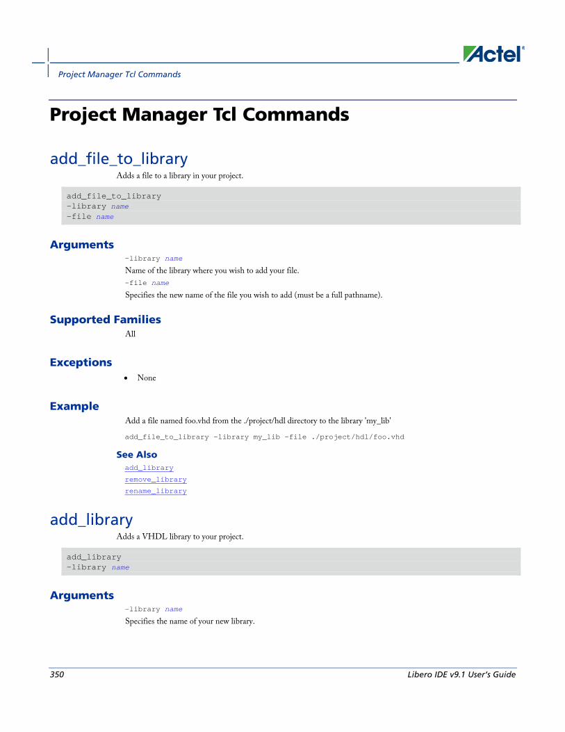
Project Manager Tcl Commands
350 Libero IDE v9.1 User’s Guide
Project Manager Tcl Commands
add_file_to_library Adds a file to a library in your project.
add_file_to_library -library name -file name
Arguments -library name
Name of the library where you wish to add your file. -file name
Specifies the new name of the file you wish to add (must be a full pathname).
Supported Families All
Exceptions • None
Example Add a file named foo.vhd from the ./project/hdl directory to the library 'my_lib'
add_file_to_library -library my_lib -file ./project/hdl/foo.vhd
See Also add_library
remove_library
rename_library
add_library Adds a VHDL library to your project.
add_library -library name
Arguments -library name
Specifies the name of your new library.

add_modelsim_path
Libero IDE v9.1 User’s Guide 351
Supported Families All
Exceptions • None
Example Create a new library called 'my_lib'.
add_library –library my_lib
See Also remove_library
rename_library
add_modelsim_path Adds a ModelSim simulation library to your project.
add_modelsim_path -lib library_name [-path library_path] [-remove " "]
Arguments -lib library_name
Name of the library you want to add. -path library_path
Path to library that you want to add. -remove " "
Name of library you want to remove (if any).
Supported Families All
Exceptions None
Example Add the ModelSim library 'msim_update2' located in the c:\modelsim\libraries directory and remove the library 'msim_update1':
add_modelsim_path -lib msim_update2 [-path c:\modelsim\libraries] [-remove msim_update1]
add_profile Sets the same values as the Add or Edit Profile dialog box.
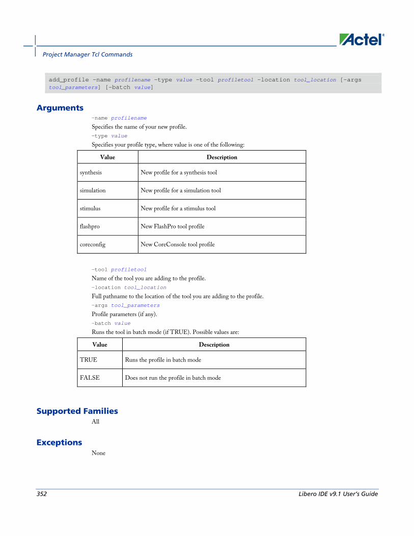
Project Manager Tcl Commands
352 Libero IDE v9.1 User’s Guide
add_profile -name profilename -type value -tool profiletool -location tool_location [-args tool_parameters] [-batch value]
Arguments -name profilename
Specifies the name of your new profile. -type value
Specifies your profile type, where value is one of the following:
Value Description
synthesis New profile for a synthesis tool
simulation New profile for a simulation tool
stimulus New profile for a stimulus tool
flashpro New FlashPro tool profile
coreconfig New CoreConsole tool profile
-tool profiletool
Name of the tool you are adding to the profile. -location tool_location
Full pathname to the location of the tool you are adding to the profile. -args tool_parameters
Profile parameters (if any). -batch value
Runs the tool in batch mode (if TRUE). Possible values are:
Value Description
TRUE Runs the profile in batch mode
FALSE Does not run the profile in batch mode
Supported Families All
Exceptions None

associate_stimulus
Libero IDE v9.1 User’s Guide 353
Example Create a new FlashPro tool profile called 'myflashpro' linked to a FlashPro installation in my c:\programs\actel\flashpro\bin directory
new_profile -name myflashpro -type flashpro -tool flashpro.exe -location c:\programs\actel\flashpro\bin\flashpro.exe -batch FALSE
associate_stimulus Associates a stimulus file in your project.
-associate_stimulus [-file name]* [-mode value] -module value
Arguments -file name
Specifies the name of the file to which you want to associate your stimulus files.
-mode value
Specifies whether you are creating a new stimulus association, adding, or removing; possible values are:
Value Description
new Creates a new stimulus file association
add Adds a stimulus file to an existing association
remove Removes an stimulus file association
-module value
Sets the module, where value is the name of the module.
Supported Families All
Exceptions None
Example The example associates a new stimulus file 'stim.vhd' for stimulus.
-associate_stimulus -file stim.vhd -mode new -module stimulus

Project Manager Tcl Commands
354 Libero IDE v9.1 User’s Guide
change_link_source Changes the source of a linked file in your project.
change_link_source -file filename -path new_source_path
Arguments -file filename
Name of the linked file you want to change. -path new_source_path
Location of the file you want to link to.
Supported Families All
Exceptions None
Example Change the link to a file 'sim1.vhd' in your project and link it to the file in c:\actel\link_source\simulation_test.vhd
change_link_source -file sim1.vhd -path c:\actel\link_source\simulation_test.vhd
check_hdl Checks the HDL in the specified file.
check_hdl -file filename
Arguments -file filename
Name of the HDL file you want to check.
Supported Families All
Exceptions None
Example Check HDL on the file hdl1.vhd.
check_hdl -file hdl1.vhd

close_project
Libero IDE v9.1 User’s Guide 355
close_project Closes the current project in Libero IDE. Equivalent to clicking the File menu, and selecting Close Project.
close_project
Arguments None
Supported Families All
Exceptions • None
Example close_project
See Also open_project
check_schematic Checks the schematic.
check_schematic -file filename
Arguments -file filename
Name of the schematic file you want to check.
Supported Families All
Exceptions None
Example Check schematic on the file schem.2vd.
check_schematic -file schem.2vd

Project Manager Tcl Commands
356 Libero IDE v9.1 User’s Guide
create_links Creates a link (or links) to a file/files in your project.
create_links [-hdl_source file]* [-stimulus file]* [-sdc file]* [-pin file]* [-dcf file]* [-gcf file]* [-pdc file]* [-crt file]* [-vcd file]*
Arguments -hdl_source file
Name of the HDL file you want to link. -stimulus file
Name of the stimulus file you want to link. -sdc file
Name of the SDC file you want to link. -pin file
Name of the PIN file you want to link. -dcf file
Name of the DCF file you want to link. -gcf file
Name of the GCF file you want to link. -pdc file
Name of the PDC file you want to link. -crt file
Name of the crt file you want to link. -vcd file
Name of the VCD file you want to link.
Supported Families All
Exceptions None
Example Create a link to the file hdl1.vhd.
create links [-hdl_source hdl1.vhd]
create_symbol Creates a symbol in a module.

delete_files
Libero IDE v9.1 User’s Guide 357
create_symbol [-module module]
Arguments -module module
Name of the symbol module you want to create.
Supported Families All
Exceptions None
Example Create a symbol named mod2.
create_symbol [-module mod2]
See Also
delete_files Deletes files in your Libero IDE project.
delete_files -file value -from_disk
Arguments -file value
Specifies the file you wish to delete from the project. This parameter is required for this Tcl command. It does not delete the file from the disk. Use the -from_disk flag to delete a file from the disk. Value is the name of the file you wish to delete (including the full pathname). -from_disk
Deletes a file from the disk.
Supported Families All
Exceptions • None
Project Manager Tcl Commands
358 Libero IDE v9.1 User’s Guide
Example Delete the files file1.vhd and file2.vhd from the project, and delete the file top_palace.sdc from the disk.
delete_files –file ./project/hdl/file1.vhd –file ./project/hdl/file2.vhd
delete_files –from_disk –file ./project/phy_synthesis/top_palace.sdc
The following command deletes the core 'add1' from your disk and project (it is the same as the command to delete an IP core from your disk and project).
delete_files -from_disk -file ./project/component/work/add1/add1.cxf
See Also close_project
new_project
edit_profile Sets the same values as the Add or Edit Profile dialog box.
edit_profile -name profilename -type value -tool profiletool -location profilelocation [-args parameters] [-batch value] [-new_name name]
Arguments -name profilename
Specifies the name of your new profile. -type value
Specifies your profile type, where value is one of the following:
Value Description
synthesis New profile for a synthesis tool
simulation New profile for a simulation tool
stimulus New profile for a stimulus tool
flashpro New FlashPro tool profile
coreconfig New CoreConsole tool profile
-tool profiletool
Name of the tool you are adding to the profile. -location profilelocation
Full pathname to the location of the tool you are adding to the profile. -args parameters
Profile tool parameters (if any). -batch value
Runs the tool in batch mode (if TRUE). Possible values are:

export_as_link
Libero IDE v9.1 User’s Guide 359
Value Description
TRUE Runs the profile in batch mode
FALSE Does not run the profile in batch mode
-new_name name
Name of new profile.
Supported Families All
Exceptions None
Example Edit a FlashPro tool profile called 'myflashpro' linked to a new FlashPro installation in my c:\programs\actel\flashpro\bin directory, change the name to updated_flashpro.
edit_profile -name myflashpro -type flashpro -tool flashpro.exe -location c:\programs\actel\flashpro\bin\flashpro.exe -batch FALSE -new_name updated_flashpro
export_as_link Exports a file to another directory and links to the file.
export_as_link -file filename -path link_path
Arguments -file filename
Name of the file you want to export as a link. -path link_path
Path of the link.
Supported Families All
Exceptions None
Example Export the file hdl1.vhd as a link to c:\actel\link_source.

Project Manager Tcl Commands
360 Libero IDE v9.1 User’s Guide
export_as_link -file hdl1.vhd -path c:\actel\link_source
export_io_constraints_from_adb Exports the I/O constraints from your project ADB file to an output file.
export_io_constraints_from_adb -adb filename -output outputfilename
Arguments -adb filename
Specifies name of the ADB file from which you want to export your I/O constraints. -output filename
Specifies the output filename for your exported I/O constraints.
Supported Families All
Exceptions None
Example The following example exports the I/O constraint file ios.pdc from the project file designer1.adb:
export_io_constraints_from_adb -adb designer1.adb -output ios.pdc
export_profiles Exports your tool profiles. Performs the same action as the Export Profiles dialog box.
export_profile -file name [-export value]
Arguments -file name
Specifies the name of your exported profile. -export value
Specifies your profile export options. The following table shows the acceptable values for this argument:
Value Description
predefined Exports only predefined profiles
user Exports only user profiles
generate_ba_files
Libero IDE v9.1 User’s Guide 361
Value Description
all Exports all profiles
Supported Families All
Exceptions None
Example The following command exports all profiles to the file 'all_profiles':
export_profiles -file all_profiles [-export all]
generate_ba_files Generates the back-annotate files for your design.
generate_ba_files -adb filename
Arguments -adb filename
Specifies name of the ADB file from which you wish to generate the backannotate files.
Supported Families All
Exceptions None
Example The following example generates backa-nnotate files from the file designer1.adb:
generate_ba_files -adb designer1.adb
generate_hdl_from_schematic Generates an HDL file from your schematic.
generate_hdl_from_schematic [-module modulename]

Project Manager Tcl Commands
362 Libero IDE v9.1 User’s Guide
Arguments -module modulename
Specifies the module name for your new HDL module
Supported Families All
Exceptions None
Example The following example generates a new HDL module module1.vhd:
generate_hdl_from_schematic [-module module1.vhd]
generate_hdl_netlist Generates the HDL netlist for your design and runs the design rule check.
generate_hdl_netlist [-netlist filename] [-run_drc value]
Arguments -netlist filename
Specifies the filename of your netlist. -run_drc value
Runs the design rule check. The following table shows the acceptable values for this argument:
Value Description
TRUE Runs the design rule check
FALSE Generates your netlist without running the design rule check
Supported Families All
Exceptions None
Example The following example generates your netlist netlist2 and runs the design rule check:
generate_hdl_netlist [-netlist netlist2][-run_drc TRUE]
import_files (Libero IDE)
Libero IDE v9.1 User’s Guide 363
import_files (Libero IDE) The import_files command imports all the files you need in your Libero IDE project.
import_files -schematic {file} -symbol {file} -smartgen_core {file} -ccp {file} -stimulus {file} -hdl_source {file} -edif {file} -sdc {file} -pin {file} -dcf {file} -pdc {file} -gcf {file} -vcd {file} -saif {file} -crt {file} -simulation {file} -profiles {file} -cxf {file} -templates {file} -ccz {file} -wf_stimulus {file} -modelsim_ini {file}
Arguments -schematic {file}
Specifies the schematics you wish to import into your IDE project. Type parameter must be repeated for each file. -symbol {file}
Specifies the symbols you wish to import into your IDE project. Type parameter must be repeated for each file. -smartgen_core {file}
Specifies the cores you wish to import into your project. Type parameter must be repeated for each file. -ccp {file}
Specifies the ARM or Cortex-M1 cores you wish to import into your project. Type parameter must be repeated for each file. -stimulus {file}
Specifies HDL stimulus files you wish to import into your project. Type parameter must be repeated for each file. -hdl_source {file}
Specifies the HDL source files you wish to import into your project. Type parameter must be repeated for each file. -edif {file}
Specifies the EDIF files you wish to import into your project. Type parameter must be repeated for each file. -constraint_sdc {file}
Specifies the SDC constraint files you wish to import into your project. Type parameter must be repeated for each file. -constraint_pin {file}

Project Manager Tcl Commands
364 Libero IDE v9.1 User’s Guide
Specifies the PIN constraint files you wish to import into your project. Type parameter must be repeated for each file. -constraint_dcf {file}
Specifies the DCF constraint files you wish to import into your project. Type parameter must be repeated for each file. -constraint_pdc {file}
Specifies the PDC constraint files you wish to import into your project. Type parameter must be repeated for each file. -constraint_gcf {file}
Specifies the GCF constraint files you wish to import into your project. Type parameter must be repeated for each file. -constraint_vcd {file}
Specifies the VCD constraint files you wish to import into your project. Type parameter must be repeated for each file. -constraint_saif {file}
Specifies the SAIF constraint files you wish to import into your project. Type parameter must be repeated for each file. -constraint_crt {file}
Specifies the CRT constraint files you wish to import into your project. Type parameter must be repeated for each file. -simulation {file}
Specifies the simulation files you wish to import into your Libero IDE project. Type parameter must be repeated for each file. -profiles {file}
Specifies the profile files you wish to import into your Libero IDE project. Type parameter must be repeated for each file. -cxf {file}
Specifies the CXF file (such as SmartDesign components) you wish to import into your Libero IDE project. Type parameter must be repeated for each file. -templates {file}
Specifies the template file you wish to import into your IDE project. -ccz {file}
Specifies the IP core file you wish to import into your project. -wf_stimulus {file}
Specifies the WaveFormer Pro stimulus file you wish to import into your project. -modelsim_ini {file}
Specifies the ModelSIM INI file that you wish to import into your project.
Supported Families All
Exceptions None

new_project
Libero IDE v9.1 User’s Guide 365
Example The command below imports the HDL source files file1.vhd and file2.vhd:
import_files -hdl_source file1.vhd –hdl_source file2.vhd
new_project Creates a new project in the Libero IDE. If you do not specify a location, Libero IDE saves the new project in your current working directory.
new_project -name project_name -location project_location -family family_name –die device_die -package package_name -hdl HDL_type
Arguments -name project_name
The name of the project. This is used as the base name for most of the files generated from Libero IDE.
-location project_location
The location of the project. Must not be an existing directory.
-family family_name
The Actel device family for your targeted design.
-die device_die
Die for your targeted design.
-package package_name
Package for your targeted design.
-hdl HDL_type
Sets the HDL type for your new project.
Value Description
VHDL Sets your new projects HDL type to VHDL
VERILOG Sets your new projects to Verilog
Supported Families All
Exceptions None
Project Manager Tcl Commands
366 Libero IDE v9.1 User’s Guide
Example Creates a new project in the directory c:/netlists/test named "project", with the HDL type VHDL for the ProASIC family.
new_project -location C:/Netlists/Test -name Project -hdl VHDL -family PA
open_project Opens an existing Libero IDE project.
open_project project_name-do_backup_on_convert value-backup_file backup_filename
Arguments project_name
Must include the complete path to the PRJ file. If you do not provide the full path, Libero IDE infers that you want to open the project from your current working directory.
-do_backup_on_convert value
Sets the option to backup your files if you open a project created in a previous version of Libero IDE.
Value Description
TRUE Creates a backup of your original project before opening
FALSE Opens your project without creating a backup
-backup_file backup_filename
Sets the name of your backup file (if you choose to do_backup_on_convert).
Supported Families All
Exceptions • None
Example Open project.prj from the c:/netlists/test directory.
open_project c:/netlists/test/project.prj
See Also close_project
new_project
save_project
organize_cdbs
Libero IDE v9.1 User’s Guide 367
organize_cdbs Enables you to organize the CDB files in your project.
organize_cdbs -file name -module name
Arguments -file name
Specifies the name of the CDB file you intend to organize.
-module name
Identifies the name of the module to which you wish to add the CDB file.
Supported Families All
Exceptions None
Example Adds the file design2.cdb to the module design_test.
organize_cdbs -file design2.cdb -module design_test
organize_constraints Organizes the constraint files in your project.
-organize_constraints [-file name]* [-mode value] -designer_view name -module value -tool value
Arguments -file name
Specifies the name of the file to which you want to associate your stimulus files.
-mode value
Specifies whether you are creating a new stimulus association, adding, or removing; possible values are:
Value Description
new Creates a new stimulus file association
Project Manager Tcl Commands
368 Libero IDE v9.1 User’s Guide
Value Description
add Adds a stimulus file to an existing association
remove Removes an stimulus file association
-designer_view name
Sets the name of the Designer View in which you wish to add the constraint file, where name is the name of the view (such as impl1).
-module value
Sets the module, where value is the name of the module.
-tool value
Identifies the intended use for the file, possible values are:
Value Description
synthesis File to be used for synthesis
designer File to be used in Designer
phsynth File to be used in physical synthesis
Supported Families All
Exceptions None
Example The example adds the constraint file delta.vhd in the Designer View impl2 for the Designer tool.
-organize_constraints -file delta.vhd -mode new -designer_view impl2 -module constraint -tool designer
organize_sources Organizes the source files in your project.
Arguments -organize_sources [-file name]*

organize_sources
Libero IDE v9.1 User’s Guide 369
[-mode value] -module value -tool value [-use_default value]
Arguments -file name
Specifies the name of the file to which you want to associate your stimulus files.
-mode value
Specifies whether you are creating a new stimulus association, adding, or removing; possible values are:
Value Description
new Creates a new stimulus file association
add Adds a stimulus file to an existing association
remove Removes an stimulus file association
-module value
Sets the module, where value is the name of the module.
-tool value
Identifies the intended use for the file, possible values are:
Value Description
synthesis File to be used for synthesis
simulation File to be used for simulation
-use_default value
Uses the default values for synthesis or simulation; possible values are:
Value Description
TRUE Uses default values for synthesis or simulation.
FALSE Uses user-defined values for synthesis or simulation
Supported Families All

Project Manager Tcl Commands
370 Libero IDE v9.1 User’s Guide
Exceptions None
Example The example organizes a new stimulus file 'stim.vhd' using default settings.
-organize_sources -file stim.vhd -mode new -module stimulus -tool synthesis -use_default TRUE
project_settings Modifies project flow settings for your Libero IDE project.
project_settings [-hdl "VHDL | VERILOG"] [-auto_update_modelsim_ini "TRUE | FALSE"] [-auto_update_viewdraw_ini "TRUE | FALSE"] [-block_mode "TRUE | FALSE"] [-auto_generate_synth_hdl "TRUE | FALSE"] [-auto_run_drc "TRUE | FALSE"] [-auto_generate_viewdraw_hdl "TRUE | FALSE"] [-auto_file_detection "TRUE | FALSE"]
Arguments -hdl "VHDL | VERILOG"
Sets your project HDL type. -auto_update_modelsim_ini "TRUE | FALSE"
Sets your auto-update modelsim.ini file option. TRUE updates the file automatically. -auto_update_viewdraw_ini "TRUE | FALSE"
Sets your auto-update viewdraw.ini file option. TRUE updates the file automatically. -block_mode "TRUE | FALSE"
Puts the Project Manager in Block mode, enables you to create blocks in your project. -auto_generate_synth_hdl "TRUE | FALSE"
Auto-generates your HDL file after synthesis (when set to TRUE). -auto_run_drc "TRUE | FALSE"
Auto-runs the design rule check immediately after synthesis (when set to TRUE). -auto_generate_viewdraw_hdl "TRUE | FALSE"
Auto-generates your HDL netlist after a Save & Check in ViewDraw (when set to TRUE). -auto_file_detection "TRUE | FALSE"
Automatically detects when new files have been added to the Libero IDE project folder (when set to TRUE).
Supported Families All
Exceptions None

refresh
Libero IDE v9.1 User’s Guide 371
Example Set your project to VHDL, do not auto-update the ModelSim INI or ViewDraw INI files, auto-generate HDL after synthesis, and enable auto-detect for files.
project_settings [-hdl "VHDL"] [-auto_update_modelsim_ini "FALSE"] [-auto_update_viewdraw_ini "FALSE"] [-block_mode "FALSE"] [-auto_generate_synth_hdl "TRUE"] [-auto_file_detection "TRUE"]
refresh Refreshes your project, updates the view and checks for updated links and files.
refresh .
Supported Families All
Exceptions None
Example refresh
remove_core Removes a core from your project.
remove_core -name core_name
Arguments -name core_name
Name of the core you want to remove.
Supported Families All
Exceptions None
Example Remove the core ip-beta2:
remove_core -name ip-beta2.ccz
Project Manager Tcl Commands
372 Libero IDE v9.1 User’s Guide
remove_library Removes a VHDL library from your project.
remove_library -library name
Arguments -library name
Specifies the name of the library you wish to remove.
Supported Families All
Exceptions • None
Example Remove (delete) a library called 'my_lib'.
remove_library –library my_lib
See Also add_library
rename_library
remove_profile Deletes a tool profile.
remove_profile -name profilename
Arguments -name profilename
Specifies the name of the profile you wish to delete.
Supported Families All
Exceptions None
Example The following command deletes the profile 'custom1':

rename_library
Libero IDE v9.1 User’s Guide 373
remove_profile -name custom1
rename_library Renames a VHDL library in your project.
rename_library -library name -name name
Arguments -library name
Identifies the current name of the library that you wish to rename. -name name
Specifies the new name of the library.
Supported Families All
Exceptions • None
Example Rename a library from 'my_lib' to 'test_lib1'
rename_library –library my_lib -name test_lib1
See Also add_library
remove_library
rollback_constraints_from_adb You can enter pin constraints from Project Manager by either using the text editor to add them to a PDC file or by using the I/O Attribute Editor..
Once you have imported I/O constraint files into Designer, you can modify the constraints with the MultiView Navigator. After modifying the constraints, you can import them back into Project Manager to replace the existing constraints.
When you use the Rollback Constraints feature, Project Manager opens the ADB file, exports the PDC file, and then replaces it with the specified PDC file.
rollback_constraints_from_adb -adb filename -output output_filename

Project Manager Tcl Commands
374 Libero IDE v9.1 User’s Guide
Arguments -adb filename
Specifies the filename of the ADB file from which you want to rollback constraints. -output output_filename
Name of the output constraints file.
Supported Families All
Exceptions None
Example The following example creates a rollback constraints PDC file called rollback1.pdc from the ADB file designer1.adb:
rollback_constraints_from_adb -file designer1.adb -output rollback1
run_designer Runs Designer with compile and layout options (if selected).
run_designer [-logfile filename] [-script filename] [-append_commands commands] [-adb value] [-compile value] [-layout value] [-export_ba value]
Arguments -logfile filename
Specifies the filename of your logfile. -script filename
Appends any scripts you wish to add to add to the flow, where filename is the name of the script. -append_commands commands
Appends commands (if any), where commands is the list of appended commands. -adb value
Creates or opens your ADB file. The following table shows the acceptable values for this argument:
Value Description
new Creates a new ADB file
open Opens an existing ADB file
default Uses the default ADB file in your Libero IDE project
-compile value
Compiles your design. The following table shows the acceptable values for this argument:

run_drc
Libero IDE v9.1 User’s Guide 375
Value Description
TRUE Runs compile
FALSE Does not run compile, proceeds to the next command
-layout value
Runs layout on your design. The following table shows the acceptable values for this argument:
Value Description
TRUE Runs layout
FALSE Does not run layout, proceeds to the next command
-export_ba value
Exports back-annotate files for your design. The following table shows the acceptable values for this argument:
Value Description
TRUE Exports back-annotate files
FALSE Does not export back-annotate files; proceeds to the next command
Supported Families All
Exceptions None
Example The following example creates a logfile named designerlog2 and runs compile and layout on the default ADB file created in your Libero IDE project:
run_designer [-logfile designerlog2] [-adb default] [-compile TRUE] [-layout TRUE]
run_drc Runs the design rule check on your netlist and generates an HDL file.
run_drc [-netlist file] [-gen_hdl value]

Project Manager Tcl Commands
376 Libero IDE v9.1 User’s Guide
Arguments -netlist file
Name of the netlist file you want the design rule check to evaluate. -gen_hdl value
Generates an HDL file (if TRUE). The following table shows the acceptable values for this argument:
Value Description
TRUE Generates an HDL file for your design
FALSE Does not generate an HDL file after the design rule check
Supported Families All
Exceptions None
Example Run the design rule check on the netlist named 'dsnr3' and generates the HDL file
run_drc [-netlist 'dsnr3'] [-gen_hdl TRUE]
run_simulation Runs simulation on your project with your default simulation tool and creates a logfile.
run_simulation [-logfile "name"] [-wlf "name"] [-dofile "name"] [-refresh_lib "value"] [-state "value"]
Arguments -logfile "name"
Name of your simulation logfile. -wlf "name"
Name of WLF file you wish to use; this command and the -dofile command are exclusive. -dofile "name"
Name of DO file you wish to use; this command and the -wlf command are exclusive. -refresh_lib "value"
Sets your library refresh option using one of the following values:
Value Description
TRUE Refreshes your simulation library

run_synthesis
Libero IDE v9.1 User’s Guide 377
Value Description
FALSE Does not refresh your simulation library
-state "value"
Identifies which simulation you want to perform.
Value Description
Pre_Synthesis Runs pre-synthesis simulation
Post_Synthesis Runs post-synthesis simulation
Post_Phy_Synthesis Runs post-synthesis physical simulation
Post_Layout Runs post-layout simulation
Supported Families All
Exceptions None
Example The following command runs post-layout simulation on your project using the DO file 'myfile.do', does not refresh the simulation library, and creates the logfile 'mylog.log':
run_simulation -logfile “Mylog.log” -dofile “Myfile.do” -refresh_lib "TRUE" -state “Post_Layout”
See Also run_synthesis
run_synthesis Runs synthesis on your project and creates a logfile.
run_synthesis [-logfile "name"] [-target "target file name"]
Arguments -logfile "name"
Name of your synthesis logfile. -target "target file name"
Project Manager Tcl Commands
378 Libero IDE v9.1 User’s Guide
Name of your synthesis target file.
Supported Families All
Exceptions None
Example Run synthesis on your project and create the logfile 'mysynlogfile', and creates the target file 'targfile'.
run_synthesis [-logfile "mysynlogfile"] [-target "targfile"]
See Also run_simulation
save_log Saves your Libero IDE log file.
save_log -file value
Arguments -file value
Value is your name for the new log file.
Supported Families All
Exceptions • None
Example Save the log file file_log.
save_log -file file_log
See Also close_project
new_project
save_project The save_project command saves the current project in Libero IDE.
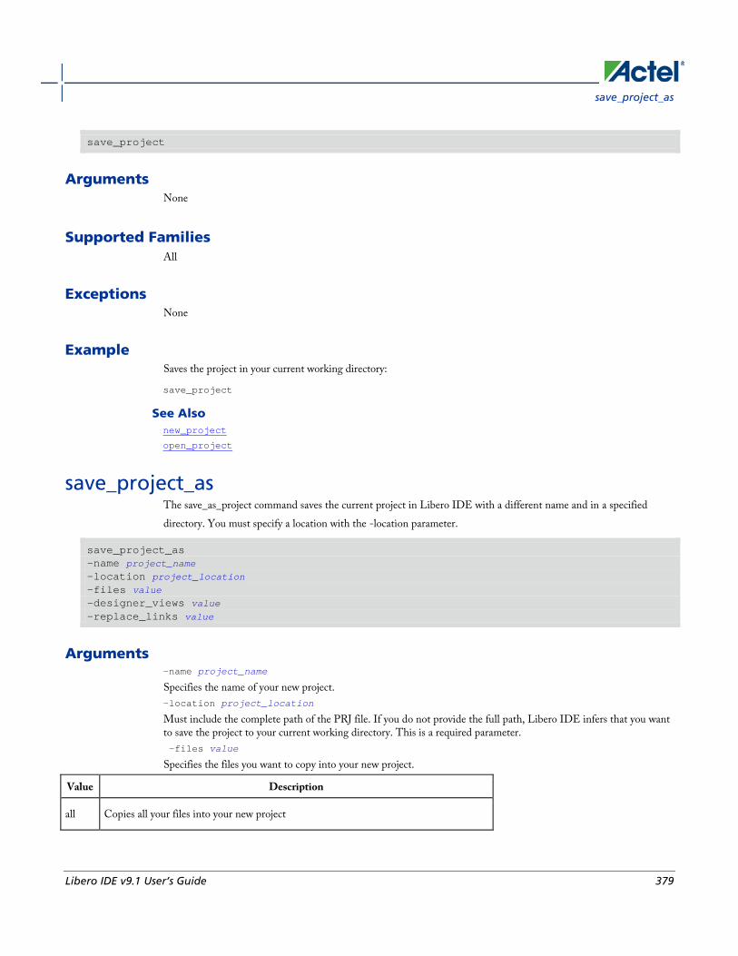
save_project_as
Libero IDE v9.1 User’s Guide 379
save_project
Arguments None
Supported Families All
Exceptions None
Example Saves the project in your current working directory:
save_project
See Also new_project
open_project
save_project_as The save_as_project command saves the current project in Libero IDE with a different name and in a specified directory. You must specify a location with the -location parameter.
save_project_as -name project_name -location project_location -files value -designer_views value -replace_links value
Arguments -name project_name
Specifies the name of your new project. -location project_location
Must include the complete path of the PRJ file. If you do not provide the full path, Libero IDE infers that you want to save the project to your current working directory. This is a required parameter. -files value
Specifies the files you want to copy into your new project.
Value Description
all Copies all your files into your new project

Project Manager Tcl Commands
380 Libero IDE v9.1 User’s Guide
Value Description
project Copies only your Libero IDE project files into your new project
source Copies only the source files into your new project
none Copies none of the files into your new project; useful if you wish to manually copy only specific project files
-designer_views value
Specifies the Designer views you wish to copy into your new project.
Value Description
all Copies all your Designer views into your new project
current Copies only your current Designer fiew files into your new project
none Copies none of your views into your new project
-replace_links value
Specifies whether or not you want to update your file links in your new project.
Value Description
true Replaces (updates) the file links in your project during your save
false Saves your project without updating the file links
Supported Families All
Exceptions None
Example Saves your current Libero IDE project as mydesign.prj in the c:/netlists/testprj/mydesign directory:
save_project_as -location c:/netlists/testprj/mydesign -name mydesign.prj
See Also new_project
open_project

select_profile
Libero IDE v9.1 User’s Guide 381
save_project
select_profile Selects a profile to use in your project.
select_profile -name profilename
Arguments -name profilename
Specifies the name of the profile you wish to use.
Supported Families All
Exceptions None
Example The following command selects the profile 'custom1':
select_profile -name custom1
set_actel_lib_options The set_actel_lib_options command sets your simulation library to default, or to another library (when you specify a path.
set_actel_lib_options -use_default_sim_path value -sim_path {path}
Arguments -use_default_sim_path value
Possible values are:
Value Description
TRUE Uses the default simulation library.
FALSE Disables the default simulation library; enables you to specify a different simulation library with the -sim_path {path} option.
-sim_path {path}
Specifies the path to your simulation library.
Project Manager Tcl Commands
382 Libero IDE v9.1 User’s Guide
Supported Families All
Exceptions None
Example Uses a simulation library in the directory c:\sim_lib\test.
set_actel_lib_options -use_default_sim_path FALSE -sim_path {c:\sim_lib\test}
set_device (Project Manager) Sets your device family, die, and package in the Project Manager.
set_device [-family family] [-die die] [-package package].
Arguments -family family
Sets device family. -die die
Sets device die. -package package
Sets device package.
Supported Families All
Exceptions None
Example Set your device to Fusion, your die to AFS600, and your package to 484 FBGA
set_device [-family fusion] [-die afs600] [-package "484 FBGA"]
set_modelsim_options Sets your ModelSim simulation options.
set_modelsim_options [-use_automatic_do_file value] [-user_do_file {path}] [-sim_runtime {value}] [-tb_module_name {value}]

set_modelsim_options
Libero IDE v9.1 User’s Guide 383
[-tb_top_level_name {value}] [-include_do_file value [-included_do_file {value}] [-type {value}] [-resolution {value}] [-add_vsim_options {value}] [-display_dut_wave value] [-log_all_signals value] [-do_file_args value] [-dump_vcd "TRUE | FALSE"] [-vcd_file "VCD file name"]
Arguments -use_automatic_do_file value
Uses an automatic.do file in your project. Possible values are:
Value Description
TRUE Uses the default automatic.do file in your project.
FALSE Uses a different *.do file; use the other simulation options to specify it.
-user_do_file {path}
Specifies the location of your user-defined *.do file.
-sim_runtime {value}
Sets your simulation runtime. Value is the number and unit of time, such as {1000ns}.
-tb_module_name {value}
Specifies your testbench module name, where value is the name.
-tb_top_level_name {value}
Sets the top-level instance name in the testbench, where value is the name.
-include_do_file value
Includes a *.do file; possible values are:
Value Description
TRUE Includes the *.do file.
FALSE Does not include the *.do file
-included_do_file {value}
Specifies the name of the included *.do file, where value is the name of the file.
-type {value}
Resolution type; possible values are:

Project Manager Tcl Commands
384 Libero IDE v9.1 User’s Guide
Value Description
min Minimum
typ Typical
max Maximum
-resolution {value}
Sets your resolution value, such as {1ps}.
-add_vsim_options {value}
Adds more Vsim options, where value specifies the option(s).
-display_dut_wave value
Enables ModelSim to display signals for the tested design; possible values are:
Value Description
0 Displays the signal for the top_level_testbench
1 Enables ModelSim to display the signals for the tested design
-log_all_signals value
Enables you to log all your signals during simulation; possible values are:
Value Description
TRUE Logs all signals
FALSE Does not log all signals
-do_file_args value
Specifies *.do file command parameters.
-dump_vcd value
Dumps the VCD file when simulation is complete; possible values are:
Value Description
TRUE Dumps the VCD file
FALSE Does not dump the VCD file

set_option
Libero IDE v9.1 User’s Guide 385
-vcd_file {value}
Specifies the name of the dumped VCD file, where value is the name of the file.
Supported Families All
Exceptions None
Example Sets ModelSim options to use the automatic *.do file, sets simulation runtime to 1000ns, sets the testbench module name to "testbench", sets the testbench top level to <top>_0, sets simulation type to "max", resolution to 1ps, adds no vsim options, does not log signals, adds no additional DO file arguments, dumps the VCD file with a name power.vcd.
set_modelsim_options -use_automatic_do_file 1 -sim_runtime {1000ns} -tb_module_name {testbench} -tb_top_level_name {<top>_0} -include_do_file 0 -type {max} -resolution {1ps} -add_vsim_options {} -display_dut_wave 0 -log_all_signals 0 -do_file_args {} -dump_vcd 0 -vcd_file {power.vcd}
set_option Sets your synthesis options on a module.
set_option [-synth "TRUE | FALSE"] [-module module]
Arguments -synth "TRUE | FALSE"
Runs synthesis (for a value of TRUE). -module module
Identifies the module on which you will run synthesis.
Supported Families All
Exceptions None
Example Run synthesis on the module test1.vhd:
set_option [-synth TRUE] [-module test1.vhd]

Project Manager Tcl Commands
386 Libero IDE v9.1 User’s Guide
set_user_lib_options Sets your user library options during simulation. If you do not use a custom library these options are not available.
set_user_lib_options -name {value} -path {path} -option {value}
Arguments -name {value}
Sets the name of your user library.
-path {path}
Sets the pathname of your user library.
-option {value}
Sets your default compile options on your user library; possible values are:
Value Description
do_not_compile User library is not compiled
refresh User library is refreshed
compile User library is compiled
recompile User library is recompiled
refresh_and_compile User library is refreshed and compiled
Supported Familes All
Exceptions None
Example The example below sets the name for the user library to "test1", the path to c:/actel_des_files/libraries/test1, and the compile option to "do not compile".
set_user_lib_options -name {test1} -path {c:/actel_des_files/libraries/test1} -option {do_not_compile}

synplify
Libero IDE v9.1 User’s Guide 387
set_root Sets the module you specify as the root.
set_root module_name
Arguments set_root module_name
Specifies the name the module you want to set as root.
Supported Families All
Exceptions None
Example Set the module mux8 as root:
set_root mux8
synplify Runs Synplify in batch mode and executes a Tcl script.
synplify –batch -licensetype synplify_acteloem <Tcl_script>.tcl
Arguments -batch
Runs Synplify in batch mode.
-licensetype synplify_acteloem <Tcl_script>.tcl
Runs Synplify and executes the Tcl script identified in the brackets; omit the brackets in the final script, as in the example below.
Exceptions None
Example The following example runs Synplify in batch mode and executes the Tcl script 'mytcl.tcl'.
synplify –batch -licensetype synplify_acteloem mytcl.tcl

Project Manager Tcl Commands
388 Libero IDE v9.1 User’s Guide
_pro Runs Synplify Pro in batch mode and executes a Tcl script.
synplify_pro –batch -licensetype synplifypro_acteloem <Tcl_script>.tcl
Arguments -batch
Runs Synplify Pro in batch mode.
-licensetype synplifypro_acteloem <Tcl_script>.tcl
Runs Synplify Pro and executes the Tcl script identified in the brackets; omit the brackets in the final script, as in the example below.
Exceptions None
Example The following example runs Synplify Pro in batch mode and executes the Tcl script 'mytcl.tcl':
synplify_pro –batch -licensetype synplifypro_acteloem mytcl.tcl
unlink Removes a link to a file in your project.
unlink -file filename [-local local_filename]
Arguments -file filename
Name of the linked (remote) file you want to unlink. -local local_filename
Name of the local file that you want to unlink.
Supported Families All
Exceptions None

use_file
Libero IDE v9.1 User’s Guide 389
Example Unlink the file hdl1.vhd from my local file test.vhd
unlink -file hdl1.vhd [-local test.vhd]
use_file Specifies which file in your project to use.
use_file -file value -module value -designer_view value
Arguments -filevalue
Specifies the EDIF or ADB file you wish to use in the project. Value is the name of the file you wish use (including the full pathname). -module value
Specifies the module in which you want to use the file. -designer_view value
Specifies the Designer View in which you wish to use the file.
Supported Families All
Exceptions • None
Example Specify file1.edn in the ./project/synthesis directory, in the module named top, in the Designer View named impl1.
use_file –file “./project/synthesis/file1.edn” –module “top” –designer_view “Impl1”
See Also use_source_file
use_source_file Defines a module for your project.
use_source_file -file value -module value

Project Manager Tcl Commands
390 Libero IDE v9.1 User’s Guide
Arguments -file value
Specifies the Verilog or VHDL file. Value is the name of the file you wish use (including the full pathname). -module value
Specifies the module in which you want to use the file.
Supported Families All
Exceptions None
Example Specify file1.vhd in the ./project/hdl directory, in the module named top.
use_source_file –file “./project/hdl/file1.vhd” –module “top"
See Also use_file
About Designer Tcl commands A Tcl (Tool Command Language) file contains scripts for simple or complex tasks. You can run scripts from either the Windows or UNIX command line or store and run a series of Tcl commands in a “.tcl” batch file. You can also run scripts from within Designer.
Designer supports the following Tcl scripting commands:
Command Action
add_probe Adds a probe to an internal net in your design, using the original name from the optimized netlist in your design. Also, this command must be used in conjunction with the generate_probes command to generate a probed ADB file (see example below).
all_inputs Returns an object representing all input and inout pins in the current design
all_outputs Returns an object representing all output and inout pins in the current design
all_registers Returns an object representing register pins or cells in the current scenario based on the given parameters
are_all_source_files_current Audits all source files and determines whether or not they are out of date / imported into the workspace

About Designer Tcl commands
Libero IDE v9.1 User’s Guide 391
Command Action
backannotate Extracts timing delays from your post layout data
check_timing_constraints Checks all timing constraints in the current timing scenario for validity
clone_scenario Creates a new timing scenario by duplicating an existing one
close_design Closes the current design
compile Performs design rule check and optimizes the input netlist before translating the source code into machine code
create_clock Creates a clock constraint on the specified ports/pins, or a virtual clock if no source is specified
create_generated_clock Creates an internally generated clock constraint on the ports/pins and defines its characteristics
create_scenario Creates a new timing scenario with the specified name
delete_probe Deletes a probe on nets in a probed ADB file
delete_scenario Deletes the specified timing scenario
export Converts a file from its current format into the specified file format, usually for use in another program
extended_run_shell Runs multiple iterations of layout through Designer
generate_probes Executes the probing and creates a new ADB file. This command is used in conjunction with the add_probe Tcl command (see example below).
get_cells Returns an object representing the cells (instances) that match those specified in the pattern argument
get_clocks Returns an object representing the clock(s) that match those specified in the pattern argument in the current timing scenario
get_current_scenario Returns the name of the current timing scenario
get_defvar Returns the value of the Designer internal variable you specify

Project Manager Tcl Commands
392 Libero IDE v9.1 User’s Guide
Command Action
get_design_filename Returns the fully qualified path of the specified design file
get_design_info Returns detailed information about your design, depending on which arguments you specify
get_nets Returns an object representing the nets that match those specified in the pattern argument
get_out_of_date_files Audits all files returns a list of filenames that are out of date
get_pins Returns an object representing the pin(s) that match those specified in the pattern argument
get_ports Returns an object representing the port(s) that match those specified in the pattern argument
import_aux Imports the specified file as an auxiliary file, which are not audited and do not require you to re-compile the design
import_source Imports the specified file as a source file, which include your netlist and design constraints
ioadvisor_apply_suggestion Applies the suggestions for the selected attribute to the selected I/O(s)
ioadvisor_commit Saves all changes in the I/O Advisor
ioadvisor_restore Restores the I/O Advisor to the initial state
ioadvisor_restore_initial_value Sets the current value for the selected attribute and I/Os to the initial value
ioadvisor_set_outdrive Sets the outdrive for the selected I/Os
ioadvisor_set_outputload Sets the output load for the selected I/Os
ioadvisor_set_slew Sets the slew for the selected I/Os
is_design_loaded Returns True if the design is loaded into Designer; otherwise, returns False
is_design_modified Returns True if the design has been modified since it was last compiled; otherwise, returns False

About Designer Tcl commands
Libero IDE v9.1 User’s Guide 393
Command Action
is_design_state_complete Returns True if the specified design state is complete (for example, you can inquire as to whether a die and package has been selected for the design); otherwise, returns False
is_source_file_current Audits the source file and determines whether or not the file is out of date / imported into the workspace
layout Place-and-route your design
layout (advanced options for the SX family) Sets advanced place-and-route features for SX family designs
layout - Axcelerator Sets advanced place-and-route features for Axcelerator family designs
list_clocks Returns details about all of the clock constraints in the current timing constraint scenario
list_clock_latencies Returns details about all of the clock latencies in the current timing constraint scenario
list_clock_uncertainties Returns the list of clock-to-clock uncertainty constraints for the current scenario.
list_disable_timings Returns the list of disable timing constraints for the current scenario
list_false_paths Returns details about all of the false paths in the current timing constraint scenario
list_generated_clocks Returns details about all of the generated clock constraints in the current timing constraint scenario
list_input_delays Returns details about all of the input delay constraints in the current timing constraint scenario
list_max_delays Returns details about all of the maximum delay constraints in the current timing constraint scenario
list_min_delays Returns details about all of the minimum delay constraints in the current timing constraint scenario
list_multicycle_paths Returns details about all of the multicycle paths in the current timing constraint

Project Manager Tcl Commands
394 Libero IDE v9.1 User’s Guide
Command Action
scenario
list_objects Returns a list of names of the objects in the specified list
list_output_delays Returns details about all of the output delay constraints in the current timing constraint scenario
list_scenarios Returns a list of names of all of the available timing scenarios
new_design Creates a new design (.adb) file in a specific location for a particular design family such as Axcelerator or ProASIC3
open_design Opens an existing design in the Designer software
pin_assign Assigns the named pin to the specified port but does not lock its assignment.
pin_commit Saves the pin assignments to the design (.adb) file.
pin_fix Locks the pin assignment for the specified port, so the pin cannot be moved during place-and-route.
pin_fix_all Locks all the assigned pins on the device so they cannot be moved during place-and-route.
pin_unassign Unassigns a specific pin from a specific port. The unassigned pin location is then available for other ports.
pin_unassign_all Unassigns all pins from a specific port.
pin_unfix Unlocks the specified pin from its port.
layout (advanced options for ProASIC Sets advanced place-and-route features for ProASIC family designs
remove_clock Removes the specified clock constraint from the current timing scenario
remove_clock_latency Removes a clock source latency from the specified clock and from all edges of the clock
remove_clock_uncertainty Removes a clock-to-clock uncertainty from the current timing scenario by specifying either its exact arguments or its ID

About Designer Tcl commands
Libero IDE v9.1 User’s Guide 395
Command Action
remove_disable_timing Removes a disable timing constraint by specifying its arguments, or its ID
remove_false_path Removes a false path from the current timing scenario by specifying either its exact arguments or its ID
remove_generated_clock Removes the specified generated clock constraint from the current scenario
remove_input_delay Removes an input delay a clock on a port by specifying both the clocks and port names or the ID of the input_delay constraint to remove
remove_max_delay Removes a maximum delay constraint in the current timing scenario by specifying either its exact arguments or its ID.
remove_min_delay Removes a minimum delay constraint in the current timing scenario by specifying either its exact arguments or its ID
remove_multicycle_path Removes a multicycle path constraint in the current timing scenario by specifying either its exact arguments or its ID
remove_output_delay Removes an ouput delay by specifying both the clocks and port names or the ID of the output_delay constraint to remove
rename_scenario Renames the specified timing scenario with the new name provided
report Generates the type of report you specify: Status, Timing, Timer Violations, Flip-flop, Power, Pin, or I/O Bank
report (Activity and Hazards Power Report) Reads a VCD file and reports transitions and hazards for each clock cycle of the VCD file.
report (Bottleneck) using SmartTime Creates a bottleneck report
report (Cycle Accurate Power Report) Reports a power waveform with one power value per clock period or half-period instead of an average power for the whole simulation
Report (Data History) Reports new features and enhancements, bug fixes and known issues for the current release that may impact the power consumption of the design
report (Datasheet) using SmartTime Creates a datasheet report
Project Manager Tcl Commands
396 Libero IDE v9.1 User’s Guide
Command Action
Report (Power) Creates a Power report, which enables you to determine if you have any power consumption problems in your design
Report (Power Scenario) Creates a scenario power report, which enables you to enter a duration for a sequence of previously defined power modes and calculate the average power consumption and the excepted battery life for this sequence.
report (Timing) using SmartTime Creates a timing report
report (Timing violations) using SmartTime Creates a timing violations report
set_clock_latency Defines the delay between an external clock source and the definition pin of a clock within SmartTime
set_clock_uncertainty Specifies a clock-to-clock uncertainty and returns the ID of the created constraint if the command succeeded
set_current_scenario Specifies the timing scenario for the Timing Analyzer to use
save_design Writes the design to the specified filename
set_defvar Sets the value of the Designer internal variable you specify >
set_design Specifies the design name, family and path in which Designer will process the design
set_device Specifies the type of device and its parameters
set_disable_timing Disables timing arcs within a cell and returns the ID of the created constraint
set_false_path Identifies paths that are considered false and excluded from the timing analysis in the current timing scenario
set_input_delay Creates an input delay on a port list by defining the arrival time of an input relative to a clock in the current scenario
set_max_delay Specifies the maximum delay for the timing paths in the current scenario
set_min_delay Specifies the minimum delay for the timing paths in the current scenario

About Designer Tcl commands
Libero IDE v9.1 User’s Guide 397
Command Action
set_multicycle_path Defines a path that takes multiple clock cycles in the current scenario
set_output_delay Defines the output delay of an output relative to a clock in the current scenario
smartpower_add_new_custom_mode Creates a new custom mode
smartpower_add_new_scenario Creates a new scenario
smartpower_add_pin_in_domain Adds a pin to either a Clock or Set domain
smartpower_change_clock_statistics Changes the default frequencies and probabilities for a specific domain
smartpower_change_setofpin_statistics Changes the default frequencies and probabilities for a specific set
smartpower_commit Saves the changes made in SmartPower to the design file (.adb) in Designer
smartpower_create_domain Creates a new clock or set domain
smartpower_edit_custom_mode Edits a custom mode
smartpower_edit_scenario Edits a scenario
smartpower_initialize_clock_with_constraints Initializes the clock frequency and the data frequency of a single clock domain with a specified clock name and the initialization options
smartpower_init_do Initializes the frequencies and probabilities for clocks, registers, set/reset nets, primary inputs, combinational outputs, enables and other sets of pins, and selects a mode for initialization
smartpower_init_set_clocks_options Initializes the clock frequency of all clock domains
smartpower_init_set_combinational_options Initializes the frequency and probability of all combinational outputs
smartpower_init_set_enables_options Initializes the clock frequency of all enable clocks with the initialization options
smartpower_init_set_othersets_options Initializes the frequency and probability of all other sets
smartpower_init_set_primaryinputs_options Initializes the frequency and probability of all primary inputs
smartpower_init_set_registers_options Initializes the frequency and probability of all register outputs

Project Manager Tcl Commands
398 Libero IDE v9.1 User’s Guide
Command Action
smartpower_init_set_set_reset_options Initializes the frequency and probability of all set/reset nets
smartpower_init_setofpins_values Initializes the frequency and probability of all sets of pins
smartpower_remove_all_annotations Removes all initialization annotations for the specified mode
smartpower_remove_custom_mode Removes a custom mode
smartpower_remove_domain Removes an existing domain
smartpower_remove_file Removes a VCD file from the specified mode
smartpower_remove_pin_enable_rate This command is obsolete and it is replaced by smartpower_remove_pin_probability
smartpower_remove_pin_frequency Removes the frequency of an existing pin
smartpower_remove_pin_of_domain Removes a clock pin or a data pin from a Clock or Set domain, respectively.
smartpower_remove_pin_probability Enables you to annotate the probability of a pin driving an enable pin
smartpower_remove_scenario Removes a scenario from the current design
smartpower_remove_vcd Removes an existing VCD file from a mode or entire design
smartpower_restore Restores previously committed constraints
smartpower_set_battery_capacity Sets the battery capacity
smartpower_set_cooling Sets the cooling style to one of the predefined types, or a custom value
smartpower_set_mode_for_analysis Sets the mode for cycle-accurate power analysis
smartpower_set_operating_condition Sets the operating conditions used in SmartPower to best, typical, or worst case
smartpower_set_pin_enable_rate This command is obsolete and it is now replaced by smartpower_set_pin_probability
smartpower_set_pin_frequency Sets the frequency of an existing pin
smartpower_set_pin_probability Enables you to annotate the probability of a pin driving an enable pin

About Designer Tcl commands
Libero IDE v9.1 User’s Guide 399
Command Action
smartpower_set_preferences Sets SmartPower preferences such as power unit, frequency unit, operating mode, operating conditions, and toggle
smartpower_set_scenario_for_analysis Sets the scenario for cycle-accurate power analysis
smartpower_set_temperature_opcond Sets the temperature in the operating conditions used in SmartPower
smartpower_set_thermalmode Sets the mode of computing junction temperature
smartpower_set_voltage_opcond Sets the voltage in the operating conditions used in SmartPower
smartpower_temperature_opcond_set_design_wide Sets the temperature for SmartPower design-wide operating conditions
smartpower_temperature_opcond_set_mode_specific Sets the temperature for SmartPower mode-specific operating conditions
smartpower_voltage_opcond_set_design_wide Sets the voltage settings for SmartPower design-wide operating conditions
smartpower_voltage_opcond_set_mode_specific Sets the voltage settings for SmartPower mode-specific use operating conditions
st_create_set Creates a set of paths to be analyzed
st_commit Saves the changes made in SmartTime to the design (.adb) file
st_edit_set Modifies the paths in a user set
st_expand_path Displays expanded path information (path details) for paths
st_list_paths Displays the list of paths in the same tabular format shown in SmartTime
st_remove_set Deletes a user set from the design
st_restore Restores constraints previously committed in SmartTime
st_set_options Sets options for timing analysis
timer_add_clock_exception Adds an exception to or from a pin with respect to a specified clock
timer_add_pass Adds the pin to the list of pins for which the path must be shown passing through in the timer
timer_add_stop Adds the specified pin to the list of pins through which the paths will not be
Project Manager Tcl Commands
400 Libero IDE v9.1 User’s Guide
Command Action
displayed in the timer
timer_commit Saves the changes made to constraints in Timer into the Designer database.
timer_get_path Displays the Timer path information in the Log window
timer_get_clock_actuals Displays the actual clock frequency in the Log window
timer_get_clock_constraints Displays the clock constraints (period/frequency and dutycycle) in the Log window
timer_get_maxdelay Displays the maximum delay constraint between two pins of a path in the Log window
timer_get_path_constraints Displays the path constraints set for maxdelay in the Timer in the Log window
timer_remove_clock_exception Removes the previously set clock constraint
timer_remove_pass Removes the previously entered path pass constraint
timer_remove_stop Removes the path stop constraint on the specified pin
timer_restore Restores previously committed constraints
timer_setenv_clock_freq Sets a required clock frequency, in MHz, for the specified clock
timer_setenv_clock_period Sets the clock period constraint for the specified clock
timer_set_maxdelay Adds a maximum delay constraint for the path
timer_remove_all_constraints Removes all the timing constraints previously entered in the Designer system
Note: Note: Tcl commands are case sensitive. However, their arguments are not.
See Also Introduction to Tcl scripting
Basic syntax
Tcl command documentation conventions The following table shows the typographical conventions used for the Tcl command syntax.

Tcl command documentation conventions
Libero IDE v9.1 User’s Guide 401
Syntax Notation Description
command -argument
Commands and arguments appear in Courier New typeface.
variable Variables appear in blue, italic Courier New typeface. You must substitute an appropriate value for the variable.
[-argumentvalue] [variable]+
Optional arguments begin and end with a square bracket with one exception: if the square bracket is followed by a plus sign (+), then users must specify at least one argument. The plus sign (+) indicates that items within the square brackets can be repeated. Do not enter the plus sign character.
Note: Note: All Tcl commands are case sensitive. However, their arguments are not.
Examples Syntax for the get_defvar command followed by a sample command:
get_defvar variable
get_defvar “DESIGN”
Syntax for the backannotate command followed by a sample command:
backannotate -name file_name -format format_type -language language -dir directory_name [-netlist] [-pin]
backannotate -dir \
{..\design} -name "fanouttest_ba.sdf" -format "SDF" -language "VERILOG" \
-netlist
Wildcard Characters You can use the following wildcard characters in names used in Tcl commands:
Wildcard What it Does
\ Interprets the next character literally
? Matches any single character
* Matches any string
[] Matches any single character among those listed between brackets (that is, [A-Z] matches any single character in the A-to-Z range)
Project Manager Tcl Commands
402 Libero IDE v9.1 User’s Guide
Note: Note: The matching function requires that you add a slash (\) before each slash in the port, instance, or net name when using wildcards in a PDC command and when using wildcards in the Find feature of the MultiView Navigator. For example, if you have an instance named “A/B12” in the netlist, and you enter that name as “A\\/B*” in a PDC command, you will not be able to find it. In this case, you must specify the name as A\\\\/B*.
Special Characters [ ], { }, and \ Sometimes square brackets ([ ]) are part of the command syntax. In these cases, you must either enclose the open and closed square brackets characters with curly brackets ({ }) or precede the open and closed square brackets ([ ]) characters with a backslash (\). If you do not, you will get an error message.
For example:
pin_assign -port {LFSR_OUT[0]} -pin 15
or
pin_assign -port LFSR_OUT\[0\] -pin 180
Note: Note: Tcl commands are case sensitive. However, their arguments are not.
Entering Arguments on Separate Lines To enter an argument on a separate line, you must enter a backslash (\) character at the end of the preceding line of the command as shown in the following example:
backannotate -dir \
{..\design} -name "fanouttest_ba.sdf" -format "SDF" -language "VERILOG" \
-netlist
See Also Introduction to Tcl scripting
Basic syntax
About Designer Tcl commands
add_probe Adds a probe to an internal net in your design, using the original name from the optimized netlist in your design. Also, this command must be used in conjunction with the generate_probes command to generate a probed ADB file (see example below).
You must complete layout before you use this command.
add_probe –net <net_name> [-pin <pin_name>] [-port <port_name>] [-assign_to_used_pin <TRUE|FALSE>]
Arguments -net <net_name>
Name of the net you want to probe. You cannot probe HARDWIRED, POWER, or INTRINSIC nets.

all_inputs
Libero IDE v9.1 User’s Guide 403
-pin <pin_name>
Name of the package pin at which you want to put the net to be probed. Argument is optional; if unspecified the net is routed to any free package pin. -port <port_name>
Name of the port you are adding. Argument is optional; if unspecified the default value is PROBE_<n>. -assign_to_used_pin <TRUE|FALSE>
Probes a net on an already used pin. The net on the existing pin will be disconnected. Argument is optional; if unspecified the net can be only routed on unused pin.
Supported Families IGLOO, ProASIC3, SmartFusion and Fusion
Exceptions None
Example The example below adds a probe to the net Count8_0/INV_0_Y on pin 7 and uses the port name PROBE_1, then generates the probe ADB file named test1.adb.
Note that generate_probes is a separate Tcl command.
add_probe -net Count8_0/INV_0_Y -assign_to_used_pin {FALSE} -pin {7} -port {PROBE_1}
generate_probes –save test1.adb
See Also delete_probe
generate_probes
Generating a Probed Design
Generate Probed Design - Add Probe(s) Dialog Box
all_inputs Returns an object representing all input and inout pins in the current design.
all_inputs
Arguments None
Supported Families IGLOO, ProASIC3, SmartFusion, Fusion, ProASICPLUS, ProASIC, Axcelerator, RTAX-S, eX, and SX-A

Project Manager Tcl Commands
404 Libero IDE v9.1 User’s Guide
Exceptions You can only use this command as part of a –from, -to, or –through argument in the following Tcl commands: set_min_delay, set_max_delay, set_multicycle_path, and set_false_path.
Examples set_max_delay -from [all_inputs] -to [get_clocks ck1]
See Also Tcl documentation conventions
all_outputs Returns an object representing all output and inout pins in the current design.
all_outputs
Arguments None
Supported Families IGLOO, ProASIC3, SmartFusion, Fusion, ProASICPLUS, ProASIC, Axcelerator, RTAX-S, eX, and SX-A
Exceptions You can only use this command as part of a –from, -to, or –through argument in the following Tcl commands: set_min_delay, set_max_delay, set_multicycle_path, and set_false_path.
Examples set_max_delay -from [all_inputs] -to [all_outputs]
See Also Tcl documentation conventions
all_registers Returns an object representing register pins or cells in the current scenario based on the given parameters.
all_registers [-clock clock_name] [-async_pins][-output_pins][-data_pins][-clock_pins]
Arguments -clock clock_name Specifies the name of the clock domain to which the registers belong. If no clock is specified, all registers in the design will be targeted.
are_all_source_files_current
Libero IDE v9.1 User’s Guide 405
-async_pins Lists all register pins that are async pins for the specified clock (or all registers asynchronous pins in the design). -output_pins Lists all register pins that are output pins for the specified clock (or all registers output pins in the design). -data_pins Lists all register pins that are data pins for the specified clock (or all registers data pins in the design). -clock_pins Lists all register pins that are data pins for the specified clock (or all registers clock pins in the design).
Supported Families IGLOO, ProASIC3, SmartFusion, Fusion, ProASICPLUS, ProASIC, Axcelerator, RTAX-S, eX, and SX-A
Exceptions You can only use this command as part of a –from, -to, or –through argument in the following Tcl commands: set_min_delay, set_max_delay, set_multicycle_path, and set_false_path.
Examples set_max_delay 2.000 -from { ff_m:CLK ff_s2:CLK } -to [all_registers -clock_pins -clock { ff_m:Q }]
See Also Tcl documentation conventions
are_all_source_files_current Audits all source files and determines whether or not they are out of date / imported into the workspace. Returns '1' if all source files are current Returns '0' if all source files are not current This command ignores the Audit settings in your ADB file.
are_all_source_files_current
Arguments None
Supported Family All
Exceptions • The command will return an error if arguments are passed.
Project Manager Tcl Commands
406 Libero IDE v9.1 User’s Guide
Example The following code will determine if your source files are current.
are_all_source_files_current
See Also get_out_of_date_files
is_source_file_current
backannotate Equivalent to executing the Back-Annotate command from the Tools menu. You can export an SDF file, after layout, along with the corresponding netlist in the VHDL or Verilog format. These files are useful in backannotated timing simulation.
Actel recommends that you export both SDF and the corresponding VHDL/Verilog files. This will avoid name conflicts in the simulation tool.
Designer must have completed layout before this command can be invoked, otherwise the command will fail.
backannotate -name file_name -format format_type -language language-dir directory_name [-netlist] [-pin]
Arguments -name file_name
Use a valid file name with this option. You can attach the file extension .sdf to the File_Name, otherwise the tool will append .sdf for you. -format format_type
Only SDF format is available for back annotation -language language
The supported Language options are:
Value Description
VHDL93 For VHDL-93 style naming in SDF
VERILOG For Verilog style naming in SDF
-dir directory_name
Specify the directory in which all the files will be extracted. -netlist
Forces a netlist to be written. The netlist will be either in Verilog or VHDL. -pin
Designer exports the pin file with this option. The .pin file extension is appended to the design name to create the pin file.
check_timing_constraints
Libero IDE v9.1 User’s Guide 407
Supported Families All
Exceptions • The -pin argument is not supported for ProASIC and ProASICPLUS families.
Examples Example 1:
backannotate
Uses default arguments and exports SDF file for back annotation
Example 2:
backannotate -dir \
{..\my_design_dir} -name "fanouttest_ba.sdf" -format "SDF" –language \ "VHDL93" –netlist
This example uses some of the options for VHDL
Example 3:
backannotate -dir \
{..\design} -name "fanouttest_ba.sdf" -format "SDF" -language "VERILOG" \
-netlist
This example uses some of the options for Verilog
Example 4:
If { [catch { backannotate -name "fanouttest_ba" -format "SDF" } ]} {
Puts “Back annotation failed”
# Handle Failure
} else {
Puts “Back annotation successful”
# Proceed with other operations
}
You can catch exceptions and respond based on the success of backannotate operation
See Also Tcl command documentation conventions
check_timing_constraints Checks all timing constraints in the current timing scenario for validity.
check_timing_constraints
Arguments None

Project Manager Tcl Commands
408 Libero IDE v9.1 User’s Guide
Supported Families IGLOO, ProASIC3, SmartFusion, Fusion, ProASICPLUS, ProASIC, Axcelerator, RTAX-S, eX, and SX-A
Exceptions None
Examples check_timing_constraints
See Also Tcl documentation conventions
clone_scenario Creates a new timing scenario by duplicating an existing one. You must provide a unique name (that is, it cannot already be used by another timing scenario).
clone_scenario name -source origin
Arguments name
Specifies the name of the new timing scenario to create. -source origin
Specifies the source of the timing scenario to clone (copy). The source must be a valid, existing timing scenario.
Supported Families IGLOO, ProASIC3, SmartFusion, Fusion, Axcelerator, and RTAX-S
Description This command creates a timing scenario with the specified name, which includes a copy of all constraints in the original scenario (specified with the -source parameter). The new scenario is then added to the list of scenarios.
Example clone_scenario scenario_A –source {Primary}
See Also create_scenario
delete_scenario
Tcl documentation conventions

close_design
Libero IDE v9.1 User’s Guide 409
close_design Closes the current design and brings Designer to a fresh state to work on a new design. This is equivalent to selecting the Close command from the File menu.
close_design
Arguments None
Supported Families All
Exceptions • None
Example if { [catch { close_design }] {
Puts “Failed to close design”
# Handle Failure
} else {
puts “Design closed successfully”
# Proceed with processing a new design
}
See Also open_design
close_design
new_design
compile Performs design rule check on the input netlist. Compile also performs some optimizations on the design through logic combining and buffer tree modifications. Compile options vary by family.
Supported Families • MX, SX, SX-A, and eX
• Axcelerator
• ProASIC, ProASICPLUS
• IGLOO, ProASIC3, SmartFusion and Fusion
Project Manager Tcl Commands
410 Libero IDE v9.1 User’s Guide
See Also Setting Compile Options
create_clock Creates a clock constraint on the specified ports/pins, or a virtual clock if no source other than a name is specified.
create_clock -period period_value [-name clock_name] [-waveform> edge_list][source_objects]
Arguments -period period_value
Specifies the clock period in nanoseconds. The value you specify is the minimum time over which the clock waveform repeats. The period_value must be greater than zero. -name clock_name
Specifies the name of the clock constraint. You must specify either a clock name or a source. -waveform edge_list
Specifies the rise and fall times of the clock waveform in ns over a complete clock period. There must be exactly two transitions in the list, a rising transition followed by a falling transition. You can define a clock starting with a falling edge by providing an edge list where fall time is less than rise time. If you do not specify -waveform option, the tool creates a default waveform, with a rising edge at instant 0.0 ns and a falling edge at instant (period_value/2)ns. source_objects
Specifies the source of the clock constraint. The source can be ports, pins, or nets in the design. If you specify a clock constraint on a pin that already has a clock, the new clock replaces the existing one. You must specify either a source or a clock name.
Supported Families IGLOO, ProASIC3, SmartFusion, Fusion, ProASICPLUS, ProASIC (for analysis), Axcelerator, RTAX-S,eX, and SX-A
Description Creates a clock in the current design at the declared source and defines its period and waveform. The static timing analysis tool uses this information to propagate the waveform across the clock network to the clock pins of all sequential elements driven by this clock source.
The clock information is also used to compute the slacks in the specified clock domain that drive optimization tools such as place-and-route.
Exceptions • None

create_generated_clock
Libero IDE v9.1 User’s Guide 411
Examples The following example creates two clocks on ports CK1 and CK2 with a period of 6, a rising edge at 0, and a falling edge at 3:
create_clock -name {my_user_clock} -period 6 CK1
create_clock -name {my_other_user_clock} –period 6 –waveform {0 3} {CK2}
The following example creates a clock on port CK3 with a period of 7, a rising edge at 2, and a falling edge at 4:
create_clock –period 7 –waveform {2 4} [get_ports {CK3}]
See Also create_generated_clock
Tcl Command Documentation Conventions
create_generated_clock Creates an internally generated clock constraint on the ports/pins and defines its characteristics.
create_generated_clock [-name name] -source reference_pin [-divide_by divide_factor] [-multiply_by multiply_factor] [-invert] source
Arguments -name name
Specifies the name of the clock constraint. -source reference_pin
Specifies the reference pin in the design from which the clock waveform is to be derived. -divide_by divide_factor
Specifies the frequency division factor. For instance if the divide_factor is equal to 2, the generated clock period is twice the reference clock period. -multiply_by multiply_factor
Specifies the frequency multiplication factor. For instance if the multiply_factor is equal to 2, the generated clock period is half the reference clock period. -invert
Specifies that the generated clock waveform is inverted with respect to the reference clock. source
Specifies the source of the clock constraint on internal pins of the design. If you specify a clock constraint on a pin that already has a clock, the new clock replaces the existing clock. Only one source is accepted. Wildcards are accepted as long as the resolution shows one pin.
Supported Families IGLOO, ProASIC3, SmartFusion, Fusion, ProASICPLUS, ProASIC (for analysis), Axcelerator, RTAX-S,eX, and SX-A
Project Manager Tcl Commands
412 Libero IDE v9.1 User’s Guide
Description Creates a generated clock in the current design at a declared source by defining its frequency with respect to the frequency at the reference pin. The static timing analysis tool uses this information to compute and propagate its waveform across the clock network to the clock pins of all sequential elements driven by this source.
The generated clock information is also used to compute the slacks in the specified clock domain that drive optimization tools such as place-and-route.
Examples The following example creates a generated clock on pin U1/reg1:Q with a period twice as long as the period at the reference port CLK.
create_generated_clock -name {my_user_clock} –divide_by 2 –source [get_ports {CLK}] U1/reg1:Q
The following example creates a generated clock at the primary output of myPLL with a period ¾ of the period at the reference pin clk.
create_generated_clock –divide_by 3 –multiply_by 4 -source clk [get_pins {myPLL:CLK1}]
See Also create_clock
Tcl Command Documentation Conventions
create_scenario Creates a new timing scenario with the specified name. You must provide a unique name (that is, it cannot already be used by another timing scenario).
create_scenario name
Arguments name
Specifies the name of the new timing scenario.
Supported Families IGLOO, ProASIC3, SmartFusion, Fusion, Axcelerator, and RTAX-S
Description A timing scenario is a set of timing constraints used with a design. Scenarios enable you to easily refine the set of timing constraints used for Timing-Driven Place-and-Route, so as to achieve timing closure more rapidly.
This command creates an empty timing scenario with the specified name and adds it to the list of scenarios.
delete_probe
Libero IDE v9.1 User’s Guide 413
Exceptions • None
Example create_scenario scenario_A
See Also clone_scenario
Tcl Command Documentation Conventions
delete_probe Deletes a probe on nets in a probed ADB file.
delete_probe –net <net_name>
Arguments -net <net_name>
Name of the net you want to delete.
Supported Families IGLOO, ProASIC3, SmartFusion and Fusion
Exceptions None
Example The example below deletes the probe on the net Count8_0/INV_0_Y.
delete_probe -net Count8_0/INV_0_Y
See Also add_probe
Generating a Probed Design
Generate Probed Design - Add Probe(s) Dialog Box_Ref2104634540
delete_scenario Deletes the specified timing scenario.
delete_scenario name
Project Manager Tcl Commands
414 Libero IDE v9.1 User’s Guide
Arguments name
Specifies the name of the timing scenario to delete.
Supported Families IGLOO, ProASIC3, SmartFusion, Fusion, Axcelerator, and RTAX-S
Description This command deletes the specified timing scenario and all the constraints it contains.
Exceptions • At least one timing scenario must always be available. If the current scenario is the only one that exists, you
cannot delete it.
• Scenarios that are linked to the timing analysis or layout cannot be deleted.
Example delete_scenario scenario_A
See Also create_scenario
Tcl Command Documentation Conventions
export The syntax and arguments for the export command vary depending on which device you are designing. Click the appropriate command in the following list to see the syntax, arguments, and other information:
• export (IGLOO, ProASIC3, SmartFusion and Fusion)
• export (ProASICPLUS, ProASIC, Axcelerator, MX, eX, and SX/SX-A)
• export (Block support for IGLOO, ProASIC3, SmartFusion, Fusion, Axcelerator, and RTAX-S)
export (IGLOO, ProASIC3, SmartFusion and Fusion) Saves your design to a file in the specified file format. The required and optional arguments this command takes depends on which file format you specify.
export [-format value] [-feature value] [-secured_device value] [-signature value] [-pass_key value] [-aes_key value]

export (IGLOO, ProASIC3, SmartFusion and Fusion)
Libero IDE v9.1 User’s Guide 415
[-from_config_file value] [-number_of_devices value] [-from_progfile_type value] [-target_programmer value] [-custom_security value] [-fpga_security_level value] [-from_security_level value] [-security_permanent value]{filename} [-from_program_pages value] [-from_content value] [-set_io_state value] [-efm_block_security {location:X;security_level: value}] [-efm_content {location:X;source:value}] [-efm_block {location:X;config_file:{value}}] [-efm_client {location:X;client: value;mem_file: value}}]
Arguments -format value
Specifies the file format of the file to export. The exported files vary from one device family to another; see the Export help topic for a description of each file type and the list of supported families. You can export the files listed in the table below using the value.
File Types Value
Netlist Files adl
afl
edn
v
vhd
Constraint Files crt
dcf
gcf
sdc
pdc
pin
Programming Files afm

Project Manager Tcl Commands
416 Libero IDE v9.1 User’s Guide
File Types Value
bit
bts_stp
dat
fus
isc
pdb
1532
svf
FlashPro Data File fdb
Debugging Files bsd
prb
Timing Files mod
sdf
stf
tcl
Script Files tcl
Log Files log
IBIS Files ibs
Other Files cob
loc
seg
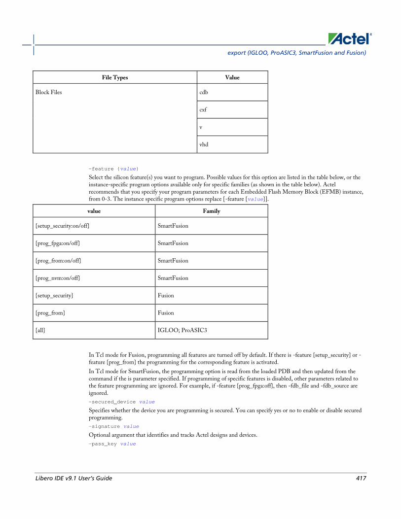
export (IGLOO, ProASIC3, SmartFusion and Fusion)
Libero IDE v9.1 User’s Guide 417
File Types Value
Block Files cdb
cxf
v
vhd
-feature {value}
Select the silicon feature(s) you want to program. Possible values for this option are listed in the table below, or the instance-specific program options available only for specific families (as shown in the table below). Actel recommends that you specify your program parameters for each Embedded Flash Memory Block (EFMB) instance, from 0-3. The instance specific program options replace [-feature {value}].
value Family
{setup_security:on/off} SmartFusion
{prog_fpga:on/off} SmartFusion
{prog_from:on/off} SmartFusion
{prog_nvm:on/off} SmartFusion
{setup_security} Fusion
{prog_from} Fusion
{all} IGLOO; ProASIC3
In Tcl mode for Fusion, programming all features are turned off by default. If there is -feature {setup_security} or -feature {prog_from} the programming for the corresponding feature is activated. In Tcl mode for SmartFusion, the programming option is read from the loaded PDB and then updated from the command if the is parameter specified. If programming of specific features is disabled, other parameters related to the feature programming are ignored. For example, if -feature {prog_fpga:off}, then -fdb_file and -fdb_source are ignored. -secured_device value
Specifies whether the device you are programming is secured. You can specify yes or no to enable or disable secured programming. -signature value
Optional argument that identifies and tracks Actel designs and devices. -pass_key value

Project Manager Tcl Commands
418 Libero IDE v9.1 User’s Guide
Protects all the security settings for FPGA Array, FlashROM, and Embedded Flash Memory Block. The maximum length of this value is 32 characters. You must use hexadecimal characters for the pass key value. -aes_key value
Decrypts FPGA Array and/or FlashROM and Embedded Flash Memory Block programming file content. Max length is 32 HEX characters. -from_config_file value
Specifies the location of the FlashROM configuration file. -number_of_devices value
Specifies the number of devices you want to program. Applicable only when FlashROM has serialization regions. -from_progfile_type value
Applicable only when FlashROM has serialization regions and STAPL file generation. Possible values:
Value Description
single Generates one programming file with all the generated incremental value(s) in the external source file
multiple Generates one individual programming file for each generated incremental value(s) in the external source file
-target_programmer value
Applicable only when FlashROM has serialization regions and STAPL file generation. Possible values:
Value Description
specific Silicon Sculptor, BP Auto Programmer, or FlashPro
generic Generic STAPL player
-custom_security value
Possible values:
Value Description
yes Custom security level
no Standard security level
-fpga_security_level value
Possible values:
Value Description
write_verify_protect The security level is medium (standard) and the FPGA Array cannot be written or verified without
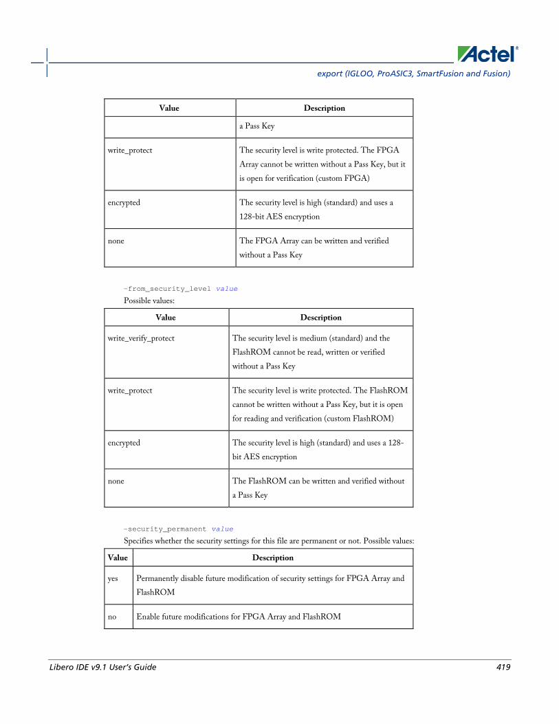
export (IGLOO, ProASIC3, SmartFusion and Fusion)
Libero IDE v9.1 User’s Guide 419
Value Description
a Pass Key
write_protect The security level is write protected. The FPGA Array cannot be written without a Pass Key, but it is open for verification (custom FPGA)
encrypted The security level is high (standard) and uses a 128-bit AES encryption
none The FPGA Array can be written and verified without a Pass Key
-from_security_level value
Possible values:
Value Description
write_verify_protect The security level is medium (standard) and the FlashROM cannot be read, written or verified without a Pass Key
write_protect The security level is write protected. The FlashROM cannot be written without a Pass Key, but it is open for reading and verification (custom FlashROM)
encrypted The security level is high (standard) and uses a 128-bit AES encryption
none The FlashROM can be written and verified without a Pass Key
-security_permanent value
Specifies whether the security settings for this file are permanent or not. Possible values:
Value Description
yes Permanently disable future modification of security settings for FPGA Array and FlashROM
no Enable future modifications for FPGA Array and FlashROM

Project Manager Tcl Commands
420 Libero IDE v9.1 User’s Guide
-from_program_pages "value"
Specifies FROM program pages in FlashPoint. If you use FlashROM content from an ADB file and do not specify a value, FlashPoint uses the same pages that were selected for programming in the previous FlashPoint session. Value may be a sequence of page numbers ("123") without a delimiter, or you can use any character or space as a delimiter, as in -from_program_pages "1 2 3". You must specify pages for programming if you want FlashROM content from the UFC file. -from_content "value"
Identifies the source file for the FlashROM content- a UFC or ADB file. If this Tcl parameter is missing, FlashPoint tries to use the ADB as a source of FROM configuration and content data. Values are shown in table below:
Value Description
adb (default)FROM content is taken from your ADB. Configurations from your UFC and ADB files are not compared.
ufc FlashPoint uses FROM configuration and FROM content from the specified UFC file
-set_io_state value
Sets the I/O state during programming by port name or pin number. You can also use this argument to save or load an IOS file. To set the I/O by port name, use -set_io_state {portName:<name>; state:<state>}. To set the I/O port by pin number, use -set_io_state {pinNumber:<number>; state:<state>}. To set all I/Os to the specified state, use -set_io_state {all; state:<state>}. To set BSR values for an I/O, use -set_io_state { pinNumber:<pin>; input:<state>; output_enable:<state>;output:<state> }. See the Boundary Scan Registers - Show BSR Details section of the FlashPoint help for more information on setting Boundary Scan Registers in your device. The following table shows the possible values for this option if you have NOT set BSR values.
Value Description
Z Tri-State - Sets the I/O state to tristate
Last Known State Sets the I/O to the last known state
1 High - Sets the I/O state to high
0 Low - Sets the I/O state to low
The following table shows the possible values for this option if you have set custom BSR values.
Value Description
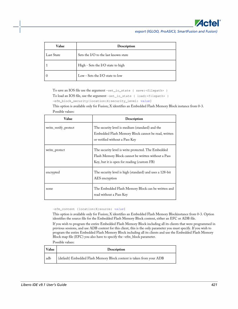
export (IGLOO, ProASIC3, SmartFusion and Fusion)
Libero IDE v9.1 User’s Guide 421
Value Description
Last State Sets the I/O to the last known state
1 High - Sets the I/O state to high
0 Low - Sets the I/O state to low
To save an IOS file use the argument -set_io_state { save:<filepath> } To load an IOS file, use the argument -set_io_state { load:<filepath> } -efm_block_security{location:X;security_level: value}
This option is available only for Fusion; X identifies an Embedded Flash Memory Block instance from 0-3. Possible values:
Value Description
write_verify_protect The security level is medium (standard) and the Embedded Flash Memory Block cannot be read, written or verified without a Pass Key
write_protect The security level is write protected. The Embedded Flash Memory Block cannot be written without a Pass Key, but it is open for reading (custom FB)
encrypted The security level is high (standard) and uses a 128-bit AES encryption
none The Embedded Flash Memory Block can be written and read without a Pass Key
-efm_content {location:X;source: value}
This option is available only for Fusion; X identifies an Embedded Flash Memory Blockinstance from 0-3. Option identifies the source file for the Embedded Flash Memory Block content, either an EFC or ADB file. If you wish to program the entire Embedded Flash Memory Block including all its clients that were programmed in previous sessions, and use ADB content for this client, this is the only parameter you must specify. If you wish to program the entire Embedded Flash Memory Block including all its clients and use the Embedded Flash Memory Block map file (EFC) you also have to specify the –efm_block parameter. Possible values:
Value Description
adb (default) Embedded Flash Memory Block content is taken from your ADB

Project Manager Tcl Commands
422 Libero IDE v9.1 User’s Guide
Value Description
efc FlashPoint uses the Embedded Flash Memory Block instance configuration and content from the EFC file specified in -efm_block_parameter
-efm_block {location:X;source: value}
This option is available only for Fusion; X identifies an Embedded Flash Memory Block (EFMB) instance from 0-3. Config_file specifies the location of the EFMB instance configuration file (must be an EFC file with full pathname). -efm_client {location:X;client:value; mem_file: value}
This option is available only for Fusion; X identifies an EFMB instance from 0-3. You must specify the client name and its memory content file for each client of EFMB you wish to program. Mem_file specifies the file with the memory content for the client. If a mem_file path is specified, the memory content from this file will overwrite the client content in ADB or EFC (as defined by the -efm_content argument). If the client memory file is not specified, the client memory content from the ADB or EFC file is used instead (as defined by the -efm_content argument). {filename}
Specifies the path and name of the file you are exporting.
Supported Families IGLOO, ProASIC3, SmartFusion and Fusion
Notes • None
Exceptions • None
Examples export -format "bts_stp"
-feature "all"
-secured_device “no”
-signature "123"
-pass_key "FB318707864EC889AE2ED8904B8EB30D"
-custom_security "no"
-fpga_security_level "write_verify_protect"
-from_security_level "write_verify_protect"
-from_config_file {.\g3_test\from.ufc}
-number_of_devices "1"
-from_progfile_type "single"
-target_programmer "specific" \
{.\flp4.stp}

export (IGLOO, ProASIC3, SmartFusion and Fusion)
Libero IDE v9.1 User’s Guide 423
The following example uses the -set_io_state argument:
export \
-format "pdb " \
-feature "setup_security" \
-secured_device "no" \
-custom_security "no" \
-security_level "write_verify_protect" \
-security_permanent "no" \
-pass_key "012EB311B02E4C9A150B0F2BD8861CA0" \
-set_io_state { portName:AG9; state:Low} \
-set_io_state { pinNumber:AG10; state:High} \
-set_io_state { pinNumber:197; state:Tri-State} \
-set_io_state { pinNumber:198; state:Low} \
-set_io_state { pinNumber:199; state:Last Known State} \
{D:/designs/Fusion/DESIGN77}
Fusion example 1:
Export soc.pdb file that includes programming data for three clients of EFM block 0. EFM block configuration file ./fus_new/nvm_simple/nvm_simple.efc and clients memory files are used for generating the programming file. Clients specified as TCL parameters must be included in EFC file.
export -format "pdb "
-efm_content {location:0; source:efc} \
-efm_block {location:0; config_file:{./fus_new/nvm_simple/nvm_simple.efc}} \
-efm_client {location:0; client:cfiData;
mem_file:{./fus_new/nvm_exmp/input_memfiles/ram1_block_0_ram1_R0C0.mem}} \
-efm_client {location:0; client:dataStorage;
mem_file:{./fus_new/nvm_exmp/input_memfiles/datast2_asb1_smtr_ram.hex}} \
-efm_client {location:0; client:init1;
mem_file:{./fus_new/nvm_exmp/input_memfiles/datast1_asb1_acm_rtc_ram.hex}} \
{./soc} Fusion example 2:
Export soc.stp and soc.pdb files that include programming data for EFM block 0. Information regarding block configuration, which clients to program, and their memory content is taken from ADB file.
export -format "pdb bts_stp"
-efm_content {location:0; source:adb} \
{./soc}
Fusion example 3:
Export soc.stp and soc.pdb files that include programming data for client cfiData of EFM block 0. Other clients of block 0 are not selected to be programmed. ADB file is a source for block configuration and content; EFC is ignored.
export -format "pdb"
-efm_content {location:0; source:adb} \
-efm_block {location:0; config_file:{./fus_new/nvm_simple/nvm_simple.efc}} \
-efm_client {location:0; client:cfiData;} \
{./soc}

Project Manager Tcl Commands
424 Libero IDE v9.1 User’s Guide
See Also export (ProASICPLUS, Axcelerator, ProASIC, MX, eX, and SX/SX-A)
Exporting files
Importing files
Tcl documentation conventions
export (ProASICPLUS, ProASIC, Axcelerator, MX, eX, and SX/SX-A) Saves your design to a file in the specified file format. The required and optional arguments for this command depend on which file format you specify.
export -format file_type{filename}
export -format edif -edif_flavor value {filename}
export -format file_type [-signature value] {filename}
export -format log [-diagnostic] (filename}
export -format sdf [-prelayout] {filename} -axprg_set_algo {programming algorithm}
Arguments -format file_type
Specifies the file format of the file to export. You can export one of the following types of files: edif, afm, dio, fus, log, sdf, adl, afl, cob, crt, dcf, design_script, loc, pin, session_script, stf, tcl, verilog, vhdl, crt, dcf, stp, pdc, stamp, gcf, prb, or sdc. -edif_flavor (value)
The acceptable values for this argument are generic, viewlogic, mgc, orcad, or workview. -signature value
Optional for afm, dio, and fus file types. -diagnostic
Optional for Log files. Specifies that you want detailed messages exported to a Log file. -prelayout
Optional for .sdf files. -axprg_set_algo {programming algorithm}
Sets the programming algorithm for your RTAX250S, RTAX1000S, or RTAX2000S device. Options are described in the table below.
Value Description
OPA Original programming algorithm; generates the OPA AFM file for your device.
UMA UMC modified algorithm; generates the UMC AFM file for your device
{filename}
Specifies the path and name of the file you are exporting.
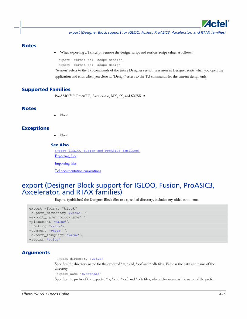
export (Designer Block support for IGLOO, Fusion, ProASIC3, Axcelerator, and RTAX families)
Libero IDE v9.1 User’s Guide 425
Notes • When exporting a Tcl script, remove the design_script and session_script values as follows:
export -format tcl -scope session
export -format tcl -scope design
"Session" refers to the Tcl commands of the entire Designer session; a session in Designer starts when you open the application and ends when you close it. "Design" refers to the Tcl commands for the current design only.
Supported Families ProASICPLUS, ProASIC, Axcelerator, MX, eX, and SX/SX-A
Notes • None
Exceptions • None
See Also export (IGLOO, Fusion,and ProASIC3 families)
Exporting files
Importing files
Tcl documentation conventions
export (Designer Block support for IGLOO, Fusion, ProASIC3, Axcelerator, and RTAX families)
Exports (publishes) the Designer Block files to a specified directory, includes any added comments.
export -format "block" -export_directory {value} \ -export_name "blockname" \ -placement "value"\ -routing "value"\ -comment "value" \ -export_language "value"\ -region "value"
Arguments -export_directory {value}
Specifies the directory name for the exported *.v, *.vhd, *.cxf and *.cdb files. Value is the path and name of the directory -export_name "blockname"
Specifies the prefix of the exported *.v, *.vhd, *.cxf, and *.cdb files, where blockname is the name of the prefix.
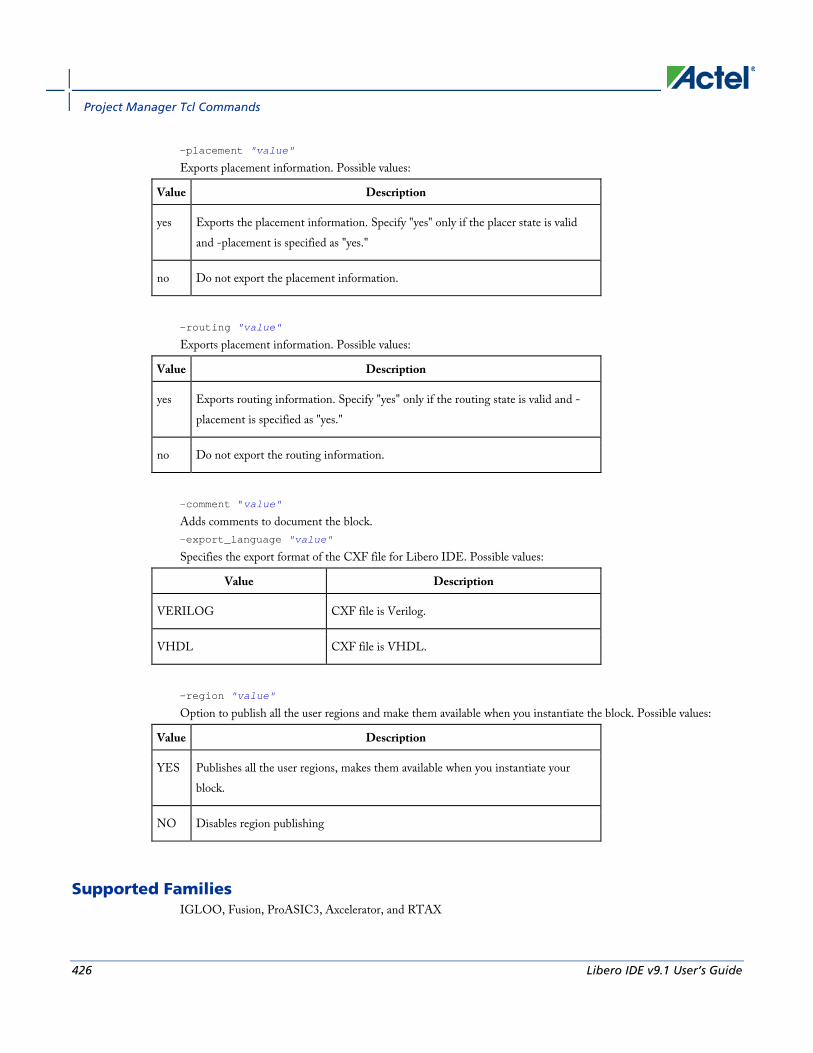
Project Manager Tcl Commands
426 Libero IDE v9.1 User’s Guide
-placement "value"
Exports placement information. Possible values:
Value Description
yes Exports the placement information. Specify "yes" only if the placer state is valid and -placement is specified as "yes."
no Do not export the placement information.
-routing "value"
Exports placement information. Possible values:
Value Description
yes Exports routing information. Specify "yes" only if the routing state is valid and -placement is specified as "yes."
no Do not export the routing information.
-comment "value"
Adds comments to document the block. -export_language "value"
Specifies the export format of the CXF file for Libero IDE. Possible values:
Value Description
VERILOG CXF file is Verilog.
VHDL CXF file is VHDL.
-region "value"
Option to publish all the user regions and make them available when you instantiate the block. Possible values:
Value Description
YES Publishes all the user regions, makes them available when you instantiate your block.
NO Disables region publishing
Supported Families IGLOO, Fusion, ProASIC3, Axcelerator, and RTAX

generate_probes
Libero IDE v9.1 User’s Guide 427
Exceptions • None
Example
export -format "block" -export_directory {.} -export_name "test_core" -placement "yes" -routing "yes" -comment "toto" -export_language "VERILOG"
See Also Exporting files
Importing files
Tcl documentation conventions
generate_probes Executes the probing and creates a new ADB file. This command is used in conjunction with the add_probe Tcl command (see example below).
generate_probes –save <ADB_file_name>
Arguments -save <ADB_file_name>
Name of the new ADB file with your probed nets.
Supported Families IGLOO, ProASIC3, SmartFusion and Fusion
Exceptions None
Example The example below adds a probe to the net net2 on pin 4 and port prb2 with the add_probe command, and generates the new ADB file test1.adb.
add_probe –net net2 –pin 4 –port prb2 generate_probes –save test1.adb
See Also add_probe
Generating a Probed Design
Generate Probed Design - Add Probe(s) Dialog Box
Project Manager Tcl Commands
428 Libero IDE v9.1 User’s Guide
get_cells Returns an object representing the cells (instances) that match those specified in the pattern argument.
get_cells pattern
Arguments pattern
Specifies the pattern to match the instances to return. For example, "get_cells U18*" returns all instances starting with the characters "U18", where “*” is a wildcard that represents any character string.
Supported Families IGLOO, ProASIC3, SmartFusion, Fusion, ProASICPLUS, ProASIC, Axcelerator, RTAX-S, eX, and SX-A
Description This command returns a collection of instances matching the pattern you specify. You can only use this command as part of a –from, -to, or –through argument in the following Tcl commands: set_max delay, set_multicycle_path, and set_false_path.
Exceptions • None
Examples set_max_delay 2 -from [get_cells {reg*}] -to [get_ports {out}]
set_false_path –through [get_cells {Rblock/muxA}]
See Also get_clocks
get_nets
get_pins
get_ports
Tcl Command Documentation Conventions
get_clocks Returns an object representing the clock(s) that match those specified in the pattern argument in the current timing scenario.
get_clocks pattern
Arguments pattern
Specifies the pattern to use to match the clocks set in SmartTime or Timer.

get_current_scenario
Libero IDE v9.1 User’s Guide 429
Supported Families IGLOO, ProASIC3, SmartFusion, Fusion, ProASICPLUS, ProASIC, Axcelerator, RTAX-S, eX, and SX-A
Description • If this command is used as a –from argument in either the set maximum (set_max_delay), or set minimum delay
(set_min_delay), false path (set_false_path), and multicycle constraints (set_multicycle_path), the clock pins of all the registers related to this clock are used as path start points.
• If this command is used as a –to argument in either the set maximum (set_max_delay), or set minimum delay (set_min_delay), false path (set_false_path), and multicycle constraints (set_multicycle_path), the synchronous pins of all the registers related to this clock are used as path endpoints.
Exceptions • None
Example set_max_delay -from [get_ports datal] -to \
[get_clocks ck1]
See Also create_clock
create_generated_clock
Tcl Command Documentation Conventions
get_current_scenario Returns the name of the current timing scenario.
get_current_scenario
Arguments None
Supported Families IGLOO, ProASIC3, SmartFusion, Fusion, Axcelerator, and RTAX-S
Exceptions None
Examples get_current_scenario

Project Manager Tcl Commands
430 Libero IDE v9.1 User’s Guide
See Also set_current_scenario
Tcl documentation conventions
get_defvar Provides access to the internal variables within Designer and returns its value. This command also prints the value of the Designer variable on the Log window.
get_defvar variable
Arguments variable
The Designer internal variable.
Supported Families All
Exceptions • None
Example Example 1: Prints the design name on the log window.
get_defvar “DESIGN”
set variableToGet "DESIGN"
set valueOfVariable [get_defvar $variableToGet]
puts "The value is $valueOfVariable"
See Also set_defvar
get_design_filename Retrieves the full qualified path of the design file. The result will be an empty string if the design has not been saved to disk. This command is equivalent to the command “get_design_info DESIGN_PATH.” This command predates get_design_info and is supported for backward-compatibility.
get_design_filename
Arguments None

get_design_info
Libero IDE v9.1 User’s Guide 431
Supported Families All
Exceptions • The command will return an error if a design is not loaded.
• The command will return an error if arguments are passed.
Example
if { [ is_design_loaded ] } {
set design_location [ get_design_filename ]
if {$design_location != "" } {
puts “Design is at $design_location.”
} else {
puts “Design has not been saved to a file on disk.”
}
} else {
puts "No design is loaded."
}
See Also get_design_info
is_design_loaded
is_design_modified
is_design_state_complete
get_design_info Retrieves some basic details of your design. The result value of the command will be a string value.
get_design_info value
Arguments value
Must be one of the valid string values summarized in the table below:
Value Description
name Design name. The result is set to the design name string.
family Silicon family. The result is set to the family name.
design_path Fully qualified path of the design file. The result is set to the location of the .adb file. If a design has not been saved to disk, the result will be an empty string. This command

Project Manager Tcl Commands
432 Libero IDE v9.1 User’s Guide
Value Description
replaces the command get_design_filename.
design_folder Directory (folder) portion of the design_path.
design_file Filename portion of the design_path.
cwdir Current working directory. The result is set to the location of the current working directory
die Die name. The result is set to the name of the selected die for the design. If no die is selected, this is an empty string.
Package Package. The result is set to the name of the selected package for the design. If no package is selected, this is an empty string.
Speed Speed grade. The result is set to the speed grade for the design. If no speed grade is selected, this is an empty string.
Supported Family All
Exceptions • Returns an error if a design is not loaded.
• Returns an error if more than one argument is passed.
• Returns an error if the argument is not one of the valid values.
Example The following example uses get_design_info to display the various values to the screen.
if { [ is_design_loaded ] } {
puts "Design is loaded."
set bDesignLoaded 1
} else {
puts "No design is loaded."
set bDesignLoaded 0
}
if { $bDesignLoaded != 0 } {
get_nets
Libero IDE v9.1 User’s Guide 433
set var [ get_design_info NAME ]
puts " DESIGN NAME:\t$var"
set var [ get_design_info FAMILY ]
puts " FAMILY:\t$var"
set var [ get_design_info DESIGN_PATH ]
puts " DESIGN PATH:\t$var"
set var [ get_design_info DESIGN_FILE ]
puts " DESIGN FILE:\t$var"
set var [ get_design_info DESIGN_FOLDER ]
puts " DESIGN FOLDER:\t$var"
set var [ get_design_info CWDIR ]
puts " WORKING DIRECTORY: $var"
set var [ get_design_info DIE ]
puts " DIE:\t$var"
set var [ get_design_info PACKAGE ]
puts " PACKAGE:\t'$var'"
set var [ get_design_info SPEED ]
puts " SPEED GRADE:\t$var"
if { [ is_design_modified ] } {
puts "The design is modified."
} else {
puts "The design is unchanged"
}
}
puts "get_design.tcl done"
See Also get_design_filename
is_design_loaded
is_design_modified
is_design_state_complete
get_nets Returns an object representing the nets that match those specified in the pattern argument.
get_nets pattern
Arguments pattern
Specifies the pattern to match the names of the nets to return. For example, "get_nets N_255*" returns all nets starting with the characters "N_255", where “*” is a wildcard that represents any character string.
Supported Families IGLOO, ProASIC3, SmartFusion, Fusion, ProASICPLUS, ProASIC, Axcelerator, RTAX-S, eX, and SX-A
Project Manager Tcl Commands
434 Libero IDE v9.1 User’s Guide
Description This command returns a collection of nets matching the pattern you specify. You can only use this command as source objects in create clock (create_clock) or create generated clock (create_generated_clock) constraints and as -through arguments in the set false path, set minimum delay, set maximum delay, and set multicycle path constraints.
Exceptions • None
Examples set_max_delay 2 -from [get_ports RDATA1] -through [get_nets {net_chkp1 net_chkqi}]
set_false_path –through [get_nets {Tblk/rm/n*}]
create_clock -name mainCLK -period 2.5 [get_nets {cknet}]
See Also create_clock
create_generated_clock
set_false_path
set_min_delay
set_max_delay
set_multicycle_path
Tcl documentation conventions
get_out_of_date_files Audits all files returns a list of filenames that are out of date; each filename is separated by a space. The command returns a string of file names that are out of date separated by a space i.e. file1 file2 ...
It returns empty string if all files are current.
This command ignores the Audit settings in your ADB file.
get_out_of_date_files
Arguments None
Supported Family All
Exceptions • None

get_pins
Libero IDE v9.1 User’s Guide 435
Example The following code returns a list of filenames that are out of date.
get_out_of_date_files
See Also are_all_source_files_curent
is_source_file_current
get_pins Returns an object representing the pin(s) that match those specified in the pattern argument.
get_pins pattern
Arguments pattern
Specifies the pattern to match the pins to return. For example, "get_pins clock_gen*" returns all pins starting with the characters "clock_gen", where “*” is a wildcard that represents any character string.
Supported Families IGLOO, ProASIC3, SmartFusion, Fusion, ProASICPLUS, ProASIC, Axcelerator, RTAX-S, eX, and SX-A
Exceptions • None
Example create_clock -period 10 [get_pins clock_gen/reg2:Q]
See Also create_clock
create_generated_clock
set_clock_latency
set_false_path
set_min_delay
set_max_delay
set_multicycle_path
Tcl documentation conventions
get_ports Returns an object representing the port(s) that match those specified in the pattern argument.
get_portspattern

Project Manager Tcl Commands
436 Libero IDE v9.1 User’s Guide
Argument pattern
Specifies the pattern to match the ports.
Supported Families IGLOO, ProASIC3, SmartFusion, Fusion, ProASICPLUS, ProASIC, Axcelerator, RTAX-S, eX, and SX-A
Exceptions • None
Example create_clock -period 10 [get_ports CK1]
See Also create_clock
set_clock_latency
set_input_delay
set_output_delay
set_min_delay
set_max_delay
set_false_path
set_multicycle_path
Tcl documentation conventions
import_aux Imports the specified auxiliary file into the design. Equivalent to executing the Import Auxiliary Files command from the File menu.
import_aux -format file_type-partial_parse value -start_time value -end_time value -auto_detect_top_level_name value -top_level_name value -glitch_filtering value -glitch_threshold value filename
Arguments -format file_type
Specifies the file format of the file to import. You can import one of the following types of files: pdc, sdc, pin, dcf, saif, vcd, or crt. -partial_parse {value}

import_aux
Libero IDE v9.1 User’s Guide 437
Specifies whether to partially parse the *.vcd file. The following table shows the acceptable values for this argument:
Value Description
true Partially parses the *.vcd file
false Does not partially parse the *.vcd file
-start_time {value}
This option is available only if -partially_parse is set to true. Specifies the start time (in ns) to partially parse the *.vcd file. -end_time {value}
This option is available only if -partially_parse is set to true. Specifies the end time (in ns) to partially parse the *.vcd file. -auto_detect_top_level_name {value}
Specifies whether to automatically detect the top-level name. The following table shows the acceptable values for this argument:
Value Description
true Automatically detects the top-level name
false Does not automatically detect the top-level name
-top_level_name top_level_name
Specifies the instance name of your design in the simulation testbench when you import a VCD or SAIF file. When importing a VCD file, the automatic top_level_name detection is available. If the -top_level_name option is not specified, SmartPower will try to automatically detect the top level name. When importing a SAIF file, the automatic top_level_name detection is not available and -top_level_name is a required argument. To identify the top_level_name for SAIF and VCD files manually, refer to Importing a VCD file and Importing a SAIF file. -glitch_filtering {value}
Specifies whether to use glitch filtering. The following table shows the acceptable values for this argument:
Value Description
true Glitch filtering is on
auto Enables automatic glitch filtering. This option will ignore any value specified in -glitch_threshold
false Glitch filtering is off
-glitch_threshold {value}
This option is only available when -glitch_filtering is set to true. Specifies the glitch filtering value in ps.

Project Manager Tcl Commands
438 Libero IDE v9.1 User’s Guide
filename
Specifies the name of the auxiliary file to import.
Supported Families IGLOO, Fusion, ProASIC3, ProASICPLUS, ProASIC, Axcelerator, MX, eX, SX/SX-A
Description • Auxiliary files are not audited and are handled as one-time data-entry or data-change events, similar to entering
data using one of the interactive editors (for example, PinEditor or Timer).
• If you import the SDC file as an auxiliary file, you do not have to re-compile your design. However, auditing is disabled when you import auxiliary files, and Designer cannot detect the changes to your SDC file(s) if you import them as auxiliary files.
Exceptions • None
Examples import_aux -format sdc file.sdc
import_aux -format pdc file.pdc
import_aux -format vcd file.vcd // automatic detection of top level name
import_aux -format vcd -glitch_filter 10 // filter out glitches that are 10 ps or less
import_aux -format saif -top_level_name "top" file.saif
See Also import_source
Importing auxiliary files
Importing source files
Importing files
Tcl documentation conventions
import_source Imports the specified source file into the design. Equivalent to executing the Import Source File command from the File menu.
All source files must be specified on one command line.
import_source [-merge_timing value][-merge_physical value][-merge_all value][-format file_type][-abort_on_error value][-top_entity][-edif -edif_flavor value]filename
Arguments -merge_timing value

import_source
Libero IDE v9.1 User’s Guide 439
Specifies whether to preserve all existing timing constraints when you import an SDC file. Same as selecting or unselecting the "Keep existing timing constraints" check box in the Import Files dialog box. The following table shows the acceptable values for this option:
Value Description
yes Designer merges the timing constraints from the imported SDC file with the existing constraints saved in the constraint database. If there is a conflict, the new constraint has priority over the existing constraint.
no All existing timing constraints are replaced by the constraints in the newly imported SDC file.
-merge_physical value
Specifies whether to preserve all existing physical constraints when you import a GCF or PDC file. Same as selecting or unselecting the "Keep existing physical constraints" check box in the Import Files dialog box. The following table shows the acceptable values for this option:
Value Description
yes Designer preserves all existing physical constraints that you have entered either using one of the MVN tools (ChipPlanner, PinEditor, or the I/O Attribute Editor) or a previous GCF or PDC file. The software resolves any conflicts between new and existing physical constraints and displays the appropriate message.
no All existing physical constraints are replaced by the constraints in the newly imported GCF or PDC file.
-merge_all value
Specifies whether to preserve all existing physical and timing constraints when you import an SDC and/or a PDC file. Same as selecting or unselecting the "Keep existing physical constraints" and "Keep existing timing constraints" check boxes in the Import Files dialog box. The following table shows the acceptable values for this option:
Value Description
yes Designer preserves all existing physical constraints that you have entered either using one of the MVN tools (ChipPlanner, PinEditor, or the I/O Attribute Editor) or a previous GCF or PDC file. The software resolves any conflicts between new and existing physical constraints and displays an appropriate message. Any existing timing constraints from your ADB are merged with the new information from your imported files. New constraints override any existing timing

Project Manager Tcl Commands
440 Libero IDE v9.1 User’s Guide
Value Description
constraints whenever there is a conflict
no All the physical constraints in the newly imported GCF or PDC files are used. All pre-existing physical constraints are lost. Existing timing constraints from the ADB are replaced by the new timing constraints from your imported file.
-format file_type
Specifies the file format of the file to import. You can import one of the following types of files: adl, edif, verilog, vhdl, gcf, pdc, sdc, or crt. Note: Note: Refer to Importing source file to know the formats supported for each family.
-abort_on_error value
Aborts a PDC file if it encounters an error during import. Possible values are
Value Description
yes Designer aborts on error.
no Designer ignores the error and continues.
-top_entity
Specifies the top entity to a VHDL file.
-edif edif_flavor value
Specifies the type of netlist. It can be edif, viewlogic, or mgc.
filename
Specifies the name of the source file to import.
Supported Families IGLOO, Fusion, ProASIC3, ProASICPLUS, Axcelerator, ProASIC, MX, eX, SX/SX-A
Exceptions Your script -merge options vary according to family as shown below:
• The -merge_timing, -merge_physical, and -merge_all arguments are available for IGLOO, Fusion, ProASIC3, ProASICPLUS, ProASIC, and Axcelerator families.
• For source SDC (no PDC/GCF) in eX and SX-A:
import_source -merge_timing yes/no ...

import_source
Libero IDE v9.1 User’s Guide 441
import_source -merge yes/no ...
import_source -merge_all yes/no ...
The eX and SX-A families do not support merging of physical constraints. For these families, in import_source, the -merge_all and -merge options are mapped just to -merge_timing.
• For constraints in ProASICPLUS:
import_source -merge_physical yes/no ...
import_source -merge_all yes/no ...
import_source -merge yes/no ...
ProASICPLUS and ProASIC support GCF, but the -merge option in the import_source only affects GCF in terms of the physical constraints.
• ProASIC does not support PreCompile import of the SDC files. The -merge_timing option has no effect on this import_source for ProASIC. The -merge_all and -merge options map to -merge_physical for ProASIC in import_source.
• For IGLOO, Fusion, ProASIC3, ProASICPLUS, and Axcelerator:
import_source -merge_physical yes/no -merge_timing yes/no ...
import_source -merge_all yes/no ...
import_source -merge yes/no ...
The -merge_all and -merge options map to both -merge_physical and -merge_timing options for these families.
Examples Consider the following sample scripts:
import_source \
-merge_physical "no" \
-merge_timing "yes"
-format "EDIF" -edif_flavor "GENERIC" \
{.\designs\mydesign.edn} \
-format "sdc" \
{.\designs\mydesign.sdc} \
-format "pdc" -abort_on_error "no" \
{.\designs\mydesign.pdc}
import_source \
-merge_physical "no" \
-format "verilog" \
{mydesign.v}
import_source \
-merge_physical "no" \
-merge_timing "no" \
-format "vhdl" -top_entity "aclass" \
{C:/mynetlist.vhd}

Project Manager Tcl Commands
442 Libero IDE v9.1 User’s Guide
import_source \
-merge_physical "no" \
-merge_timing "no" \
-format "adl" {mydesign.adl}
See Also import_aux
Importing auxiliary files
Importing source files
Importing files
Tcl documentation conventions
ioadvisor_apply_suggestion Applies the suggestions for the selected attribute to the selected I/O(s).
ioadvisor_apply_suggestion -attribute {value} -io {value}
Arguments -attribute{value}
This specifies the attribute for which the values will be applied. The following table shows the acceptable values for this argument:
Value Description
outdrive Applies suggested outdrive values
slew Applies suggested slew values
-io {value}
This selects the I/Os for which the suggestion will be applied. To select multiple I/Os, use -io {value} for each I/O.
Supported Families All
Exceptions • None
Example The following code applies the suggested outdrive values for two I/Os.
ioadvisor_apply_suggestion -attribute{outdrive} -io{nPWM_out_pad} -io{PWM_out_pad}
ioadvisor_commit
Libero IDE v9.1 User’s Guide 443
See Also ioadvisor_commit
ioadvisor_restore
ioadvisor_restore_initial_value
ioadvisor_set_outdrive
ioadvisor_set_outputload
ioadvisor_set_slew
ioadvisor_commit Saves all changes in the I/O Advisor.
ioadvisor_commit
Arguments • None
Supported Families All
Exceptions • None
Example The following code saves all changes in the I/O Advisor:
ioadvisor_commit
See Also ioadvisor_apply_suggestion
ioadvisor_restore
ioadvisor_restore_initial_value
ioadvisor_set_outdrive
ioadvisor_set_outputload
ioadvisor_set_slew
ioadvisor_restore Restores the I/O Advisor to the initial state. All changes not committed will be lost.
ioadvisor_restore

Project Manager Tcl Commands
444 Libero IDE v9.1 User’s Guide
Arguments • None
Supported Families All
Exceptions • None
Example The following code restores the I/O Advisor to the initial state:
ioadvisor_restore
See Also ioadvisor_apply_suggestion
ioadvisor_commit
ioadvisor_restore_initial_value
ioadvisor_set_outdrive
ioadvisor_set_outputload
ioadvisor_set_slew
ioadvisor_restore_initial_value Sets the current value for the selected attribute and I/Os to the initial value.
ioadvisor_restore_initial_value -attribute {value} -io {value}
Arguments -attribute{value}
This specifies the attribute for which the values will be restored. The following table shows the acceptable values for this argument:
Value Description
outdrive Restores initial outdrive values
output_load Restores initial output load values
slew Restores initial slew values
-io {value}
This selects the I/Os for which the initial values will be restored. To select multiple I/Os, use -io {value} for each I/O.
ioadvisor_set_outdrive
Libero IDE v9.1 User’s Guide 445
Supported Families All
Exceptions • None
Example The following code restores the initial outdrive values for two I/Os.
ioadvisor_restore_initial_value -attribute{outdrive} -io{nPWM_out_pad} -io{PWM_out_pad}
See Also ioadvisor_apply_suggestion
ioadvisor_commit
ioadvisor_restore
ioadvisor_set_outdrive
ioadvisor_set_outputload
ioadvisor_set_slew
ioadvisor_set_outdrive Sets the outdrive for the selected I/Os.
ioadvisor_set_outdrive -io {value} -outdrive {value}
Arguments -io {value}
This selects the I/Os for which the outdrive will be set. To select multiple I/Os, use -io {value} for each I/O. -outdrive {value}
This specifies the outdrive for the selected I/Os.The outdrive must be a positive integer value within the list of possible outdrives of the I/Os.
Supported Families All
Exceptions • None
Example The following code sets the outdrive for two I/Os.
ioadvisor_set_outdrive -io{nPWM_out_pad} -io{PWM_out_pad} -outdrive{5}

Project Manager Tcl Commands
446 Libero IDE v9.1 User’s Guide
See Also ioadvisor_apply_suggestion
ioadvisor_commit
ioadvisor_restore
ioadvisor_restore_initial_value
ioadvisor_set_outputload
ioadvisor_set_slew
ioadvisor_set_outputload Sets the output load for the selected I/Os.
ioadvisor_set_outputload -io {value} -outload {value}
Arguments -io {value}
This selects the I/Os for which the output load will be set. To select multiple I/Os, use -io {value} for each I/O. -outload {value}
This specifies the output load for the selected I/Os.The output load must be a positive integer value.
Supported Families All
Exceptions • None
Example The following code sets the output load for two I/Os.
ioadvisor_set_outputload -io{nPWM_out_pad} -io{PWM_out_pad} -outload{5}
See Also ioadvisor_apply_suggestion
ioadvisor_commit
ioadvisor_restore
ioadvisor_restore_initial_value
ioadvisor_set_outdrive
ioadvisor_set_slew
ioadvisor_set_slew Sets the slew for the selected I/Os.
ioadvisor_set_slew -io {value} -slew {value}

is_design_loaded
Libero IDE v9.1 User’s Guide 447
Arguments -io {value}
This selects the I/Os for which the slew will be set. To select multiple I/Os, use -io {value} for each I/O. -set_slew {value}
This specifies the slew for the selected I/Os.The following table shows the acceptable values for this argument:
Value Description
high The slew is set to high.
low The slew is set to low. This option is not available for all I/Os.
Supported Families All
Exceptions • None
Example The following code sets the slew for two I/Os.
ioadvisor_set_slew -io{nPWM_out_pad} -io{PWM_out_pad} -slew{high}
See Also ioadvisor_apply_suggestion
ioadvisor_commit
ioadvisor_restore
ioadvisor_restore_initial_value
ioadvisor_set_outdrive
ioadvisor_set_outputload
is_design_loaded Returns a Boolean value (0 for false, 1 for true) indicating if a design is loaded in the Designer software. True is returned if a design is currently loaded.
is_design_loaded
Arguments None
Project Manager Tcl Commands
448 Libero IDE v9.1 User’s Guide
Supported Family All
Description Some Tcl commands are valid only if a design is currently loaded in Designer. Use the ‘is_design_loaded’ command to prevent runtime errors by checking for this before invoking the commands.
Exceptions • The command will return an error if arguments are passed.
Example The following code will determine if a design has been loaded.
set bDesignLoaded [ is_design_loaded ]
if { $bDesignLoaded == 0 } {
puts “No design is loaded.”
}
See Also get_design_filename
get_design_info
is_design_modified
is_design_state_complete
is_design_modified Returns a Boolean value (0 for false, 1 for true) indicating if a design has been modified in the Designer software. True is returned if a design has been modified.
is_design_modified
Arguments None
Supported Family All
Description Some Tcl commands are valid only if a design has been modified in Designer. Use the is_design_modified command to prevent runtime errors by checking for this before invoking the commands.

is_design_state_complete
Libero IDE v9.1 User’s Guide 449
Exceptions • Returns an error if arguments are passed.
Example The following code will determine if a design has been modified.
set bDesignModified [ is_design_modified ]
if { $bDesignModified == 0 } {
puts “Design has not been modified.”
}
See Also get_design_filename
get_design_info
is_design_loaded
is_design_state_complete
is_design_state_complete Returns a Boolean value (0 for false, 1 for true) indicating if a specific design state is valid. True is returned if the specified design state is valid.
is_design_state_complete value
Arguments value
Must be one of the valid string values summarized in the table below:
Value Description
SETUP_DESIGN The design is loaded and the family has been specified for the design
DEVICE_SELECTION The design has completed device selection (die and package). This corresponds to having successfully called the set_device command to set the die and package
NETLIST_IMPORT The design has imported a netlist
COMPILE The design has completed the compile command
LAYOUT The design has completed the layout command
BACKANNOTATE The design has exported a post-layout timing file (e.g.SDF)
Project Manager Tcl Commands
450 Libero IDE v9.1 User’s Guide
Value Description
PROGRAMMING_FILES The design has exported a programming file (e.g. AFM)
Supported Family All
Description Certain commands can only be used after Compile or Layout has been completed. The is_design_state_complete command allows a script to check the design state before calling one of these state-limited commands.
Exceptions • The command will return an error if a design is not loaded.
• The command will return an error if more than one argument is passed.
• The command will return an error if the argument is not one of the valid values.
Example The following code runs layout, but checks that the design state for layout is complete before calling backannotate.
layout –timing_driven
set bLayoutDone [ is_design_state_complete LAYOUT ]
if { $bLayoutDone != 0 } {
backannotate -name {mydesign_ba} -format "SDF" -language "verilog"
}
}
See Also compile
get_design_filename
get_design_info
is_design_loaded
is_design_modified
layout
set_design
set_device
is_source_file_current Audits the source file and determines whether or not the file is out of date / imported into the workspace. Returns '0' if file_name is out of date or has not been imported into the workspace, and returns '1' if file_name is current.
This command ignores the Audit settings in your ADB file.

layout - IGLOO, ProASIC3, SmartFusion and Fusion
Libero IDE v9.1 User’s Guide 451
is_source_file_current(filename)
Arguments filename is the path to the source file
Supported Families All
Exceptions • None
Example The following code determines whether or not the file has been imported into the workspace.
is_source_file_current (./hdl/adder.vhd)
See Also are_all_source_files_curent
get_out_of_date_files
layout - IGLOO, ProASIC3, SmartFusion and Fusion This command is identical to the layout command in the Designer GUI. Refer to the Advanced Layout Options below for more information.
layout [-timing_driven | -standard] [–power_driven value] [-run_placer value] [–place_incremental value] [–run_router value] [–route_incremental value]
Arguments -timing_driven|-standard
Sets layout mode to be timing driven or standard (non-timing driven). The default is -timing_driven or the mode used in the previous layout command. -power_driven value
The following table shows the acceptable values for this argument:
Value Description
off Does not run power-driven layout. This is the default.
on Enables power-driven layout

Project Manager Tcl Commands
452 Libero IDE v9.1 User’s Guide
-place_incremental value
The following table shows the acceptable values for this argument:
Value Description
off Discards previous placement. This is the default.
on Sets the previous placement as the initial starting point
fix Sets the previously placed macros' locations as "fixed" and continues to place the remaining ones
-route_incremental value
The following table shows the acceptable values for this argument:
Value Description
off Skips incremental mode, discards previous information. This is the default.
on Invokes incremental routing and sets the previous routing information as the initial starting point
-run_placer value
The following table shows the acceptable values for this argument:
Value Description
on Invokes placement. This is the default.
off Skips placement
-run_router value
The following table shows the acceptable values for this argument:
Value Description
on Invokes routing if placement is successful. This is the default.
off Skips routing
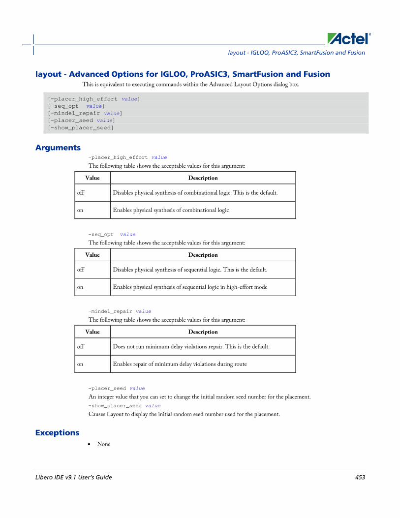
layout - IGLOO, ProASIC3, SmartFusion and Fusion
Libero IDE v9.1 User’s Guide 453
layout - Advanced Options for IGLOO, ProASIC3, SmartFusion and Fusion This is equivalent to executing commands within the Advanced Layout Options dialog box.
[-placer_high_effort value] [–seq_opt value] [–mindel_repair value] [–placer_seed value] [–show_placer_seed]
Arguments -placer_high_effort value
The following table shows the acceptable values for this argument:
Value Description
off Disables physical synthesis of combinational logic. This is the default.
on Enables physical synthesis of combinational logic
-seq_opt value
The following table shows the acceptable values for this argument:
Value Description
off Disables physical synthesis of sequential logic. This is the default.
on Enables physical synthesis of sequential logic in high-effort mode
-mindel_repair value
The following table shows the acceptable values for this argument:
Value Description
off Does not run minimum delay violations repair. This is the default.
on Enables repair of minimum delay violations during route
-placer_seed value
An integer value that you can set to change the initial random seed number for the placement. -show_placer_seed value
Causes Layout to display the initial random seed number used for the placement.
Exceptions • None

Project Manager Tcl Commands
454 Libero IDE v9.1 User’s Guide
Example layout layout –place_incremental FIX –route_incremental ON layout –placer_high_effort ON layout –run_placer OFF –route_incremental ON –mindel_repair ON layout –timing_driven –power_driven ON layout –placer_seed 120
See Also IGLOO, ProASIC3, SmartFusion and Fusion Layout options
IGLOO, ProASIC3, SmartFusion and Fusion Advanced Layout options
layout - ProASIC and ProASICPLUS This command is identical to the layout command in the Designer GUI. Refer to the Advanced Layout Options below for more information.
layout [-timing_driven | -standard] [–place_incremental value] [–route_incremental value] [-run_placer value] [–run_router value]
Arguments -timing_driven|-standard
Sets layout mode to be timing driven or standard (non-timing driven). The default is -timing_driven or the mode used in the previous layout command. -place_incremental value
The following table shows the acceptable values for this argument:
Value Description
off Discards previous placement. This is the default.
on Sets the previous placement as the initial starting point
fix Sets the previously placed macros’ locations as “FIXED” and continues to place the remaining ones
-route_incremental value
The following table shows the acceptable values for this argument:
Value Description
off Skips incremental mode, discards previous information. This is the default.
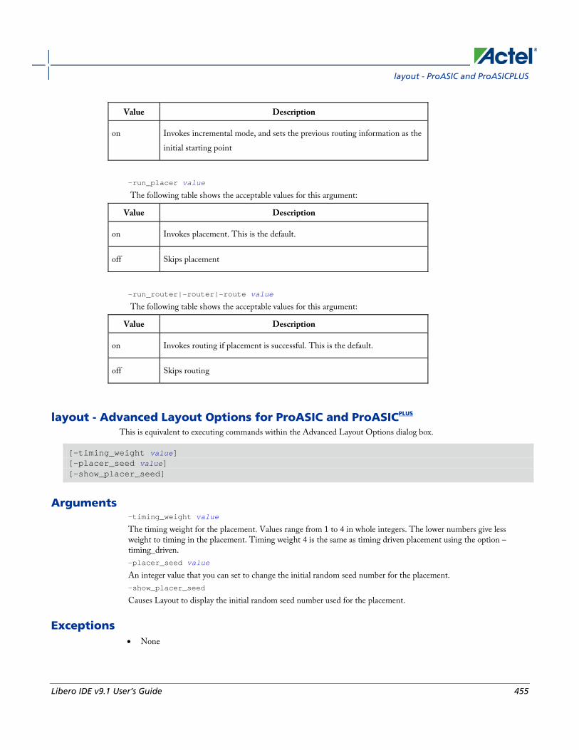
layout - ProASIC and ProASICPLUS
Libero IDE v9.1 User’s Guide 455
Value Description
on Invokes incremental mode, and sets the previous routing information as the initial starting point
-run_placer value
The following table shows the acceptable values for this argument:
Value Description
on Invokes placement. This is the default.
off Skips placement
-run_router|-router|-route value
The following table shows the acceptable values for this argument:
Value Description
on Invokes routing if placement is successful. This is the default.
off Skips routing
layout - Advanced Layout Options for ProASIC and ProASICPLUS This is equivalent to executing commands within the Advanced Layout Options dialog box.
[–timing_weight value] [–placer_seed value] [–show_placer_seed]
Arguments -timing_weight value
The timing weight for the placement. Values range from 1 to 4 in whole integers. The lower numbers give less weight to timing in the placement. Timing weight 4 is the same as timing driven placement using the option –timing_driven. -placer_seed value
An integer value that you can set to change the initial random seed number for the placement. -show_placer_seed
Causes Layout to display the initial random seed number used for the placement.
Exceptions • None

Project Manager Tcl Commands
456 Libero IDE v9.1 User’s Guide
Example layout
layout –standard
layout –timing_weight 3
layout –place_incremental FIX –route_incremental ON
layout –placer_seed 120
See Also ProASICPLUS and ProASIC Layout Options
ProASICPLUS, ProASIC Advanced Layout Options
layout - Axcelerator This command is identical to the layout command in the Designer GUI. Refer to the Advanced Layout Options below for more information.
layout [-timing_driven | -standard] [–power_driven value] [–place_incremental value] [–effort_level value] [–route_incremental value] [-run_placer value] [–run_router value]
Arguments -timing_driven|-standard
Sets layout mode to be timing driven or standard (non-timing driven). The default is -timing_driven or the mode used in the previous layout command. -power_driven value
The following table shows the acceptable values for this argument:
Value Description
off Does not run power-driven layout. This is the default.
on Enables power-driven layout
-place_incremental value
The following table shows the acceptable values for this argument:
Value Description
off Discards previous placement. This is the default
on Sets the previous placement as the initial starting point
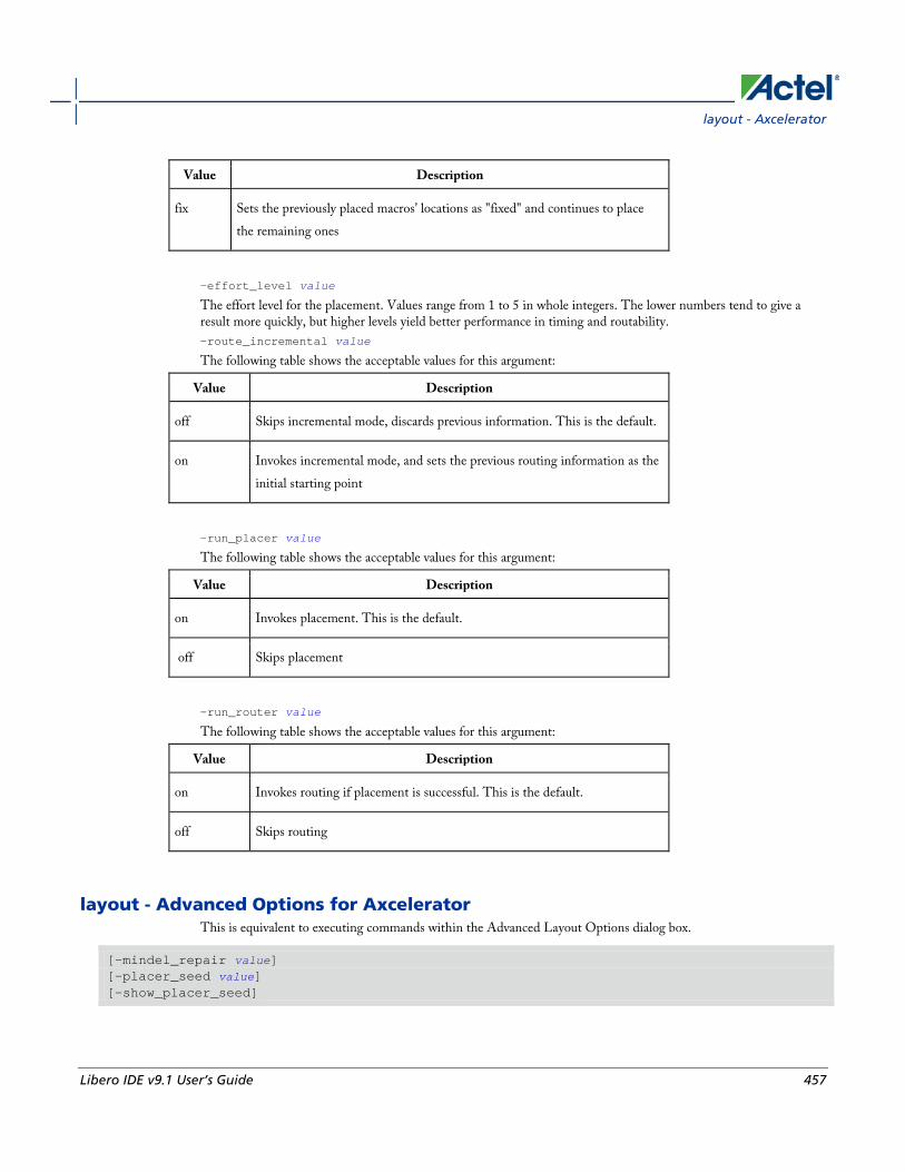
layout - Axcelerator
Libero IDE v9.1 User’s Guide 457
Value Description
fix Sets the previously placed macros’ locations as "fixed" and continues to place the remaining ones
-effort_level value
The effort level for the placement. Values range from 1 to 5 in whole integers. The lower numbers tend to give a result more quickly, but higher levels yield better performance in timing and routability. -route_incremental value
The following table shows the acceptable values for this argument:
Value Description
off Skips incremental mode, discards previous information. This is the default.
on Invokes incremental mode, and sets the previous routing information as the initial starting point
-run_placer value
The following table shows the acceptable values for this argument:
Value Description
on Invokes placement. This is the default.
off Skips placement
-run_router value
The following table shows the acceptable values for this argument:
Value Description
on Invokes routing if placement is successful. This is the default.
off Skips routing
layout - Advanced Options for Axcelerator This is equivalent to executing commands within the Advanced Layout Options dialog box.
[–mindel_repair value] [–placer_seed value] [–show_placer_seed]
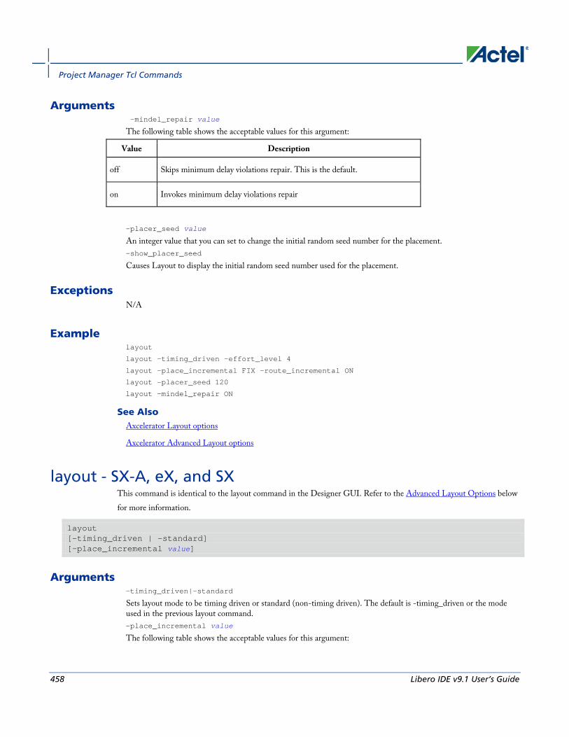
Project Manager Tcl Commands
458 Libero IDE v9.1 User’s Guide
Arguments -mindel_repair value
The following table shows the acceptable values for this argument:
Value Description
off Skips minimum delay violations repair. This is the default.
on Invokes minimum delay violations repair
-placer_seed value
An integer value that you can set to change the initial random seed number for the placement. -show_placer_seed
Causes Layout to display the initial random seed number used for the placement.
Exceptions N/A
Example layout
layout –timing_driven –effort_level 4
layout –place_incremental FIX –route_incremental ON
layout –placer_seed 120
layout –mindel_repair ON
See Also Axcelerator Layout options
Axcelerator Advanced Layout options
layout - SX-A, eX, and SX This command is identical to the layout command in the Designer GUI. Refer to the Advanced Layout Options below for more information.
layout [-timing_driven | -standard] [–place_incremental value]
Arguments -timing_driven|-standard
Sets layout mode to be timing driven or standard (non-timing driven). The default is -timing_driven or the mode used in the previous layout command. -place_incremental value
The following table shows the acceptable values for this argument:

layout - SX-A, eX, and SX
Libero IDE v9.1 User’s Guide 459
Value Description
off Discards previous placement. This is the default.
on Sets the previous placement as the initial starting point
fix Sets the previously placed macros’ locations as “FIXED” and continues to place the remaining ones
layout - Advanced Options for SX-A, eX, and SX This is equivalent to executing commands within the Advanced Layout Options dialog box.
[-extended_run value] [-effort_level value] [-timing_weight value] [-placer_seed value] [-show_placer_seed value]
Arguments -extended_run value
The following table shows the acceptable values for this argument:
Value Description
off Skips extended run mode. This is the default.
on Invokes extended run mode
-effort_level value
Sets the effort level; number may range from 25 to 500. -timing_weight value
Sets the timing weight value; number may range from 10 to 150. -placer_seed value
An integer value that you can set to change the initial random seed number for the placement. -show_placer_seed
Causes Layout to display the initial random seed number used for the placement.
Exceptions • None
Example layout [-timing_driven] [-incremental OFF] [-extended_run OFF] [-effort_level 50] [-timing_weight 100]

Project Manager Tcl Commands
460 Libero IDE v9.1 User’s Guide
See Also eX, SX, and SX-A Layout options
eX, SX, and SX-A Advanced Layout options
layout - MX, DX, ACT This command is identical to the layout command in the Designer GUI. Refer to the Advanced Layout Options below for more information.
layout [-timing_driven | -standard] [–place_incremental value]
Arguments -timing_driven|-standard
Sets layout mode to be timing driven or standard (non-timing driven). The default is -timing_driven or the mode used in the previous layout command. -place_incremental value
The following table shows the acceptable values for this argument:
Value Description
off Discards previous placement. This is the default.
on Sets the previous placement as the initial starting point
fix Sets the previously placed macros’ locations as "fixed" and continues to place the remaining ones
layout - Advanced Options for MX, DX, ACT This is equivalent to executing commands within the Advanced Layout Options dialog box.
[-extended_run value] [–placer_seed value] [–show_placer_seed]
Arguments -extended_run value
The following table shows the acceptable values for this argument:
Value Description
off Skips extended run mode. This is the default.

list_clocks
Libero IDE v9.1 User’s Guide 461
Value Description
on Invokes extended run mode
-placer_seed value
An integer value that you can set to change the initial random seed number for the placement. -show_placer_seed
Causes Layout to display the initial random seed number used for the placement.
Exceptions • None
Example The following code runs layout and specifies the timing-driven option:
layout –timing_driven
See Also MX, DX, and ACT Layout options
MX, DX, and ACT Advanced Layout options
list_clocks Returns details about all of the clock constraints in the current timing constraint scenario.
list_clocks
Arguments None
Supported Families IGLOO, ProASIC3, SmartFusion, Fusion, ProASICPLUS, ProASIC, Axcelerator, RTAX-S, eX, and SX-A
Exceptions None
Examples puts [list_clocks]
See Also create_clock
remove_clock

Project Manager Tcl Commands
462 Libero IDE v9.1 User’s Guide
Tcl documentation conventions
list_clock_latencies Returns details about all of the clock latencies in the current timing constraint scenario.
list_clock_latencies
Arguments None
Supported Families IGLOO, ProASIC3, SmartFusion, Fusion, ProASICPLUS, ProASIC, Axcelerator, RTAX-S, eX, and SX-A
Exceptions None
Examples puts [list_clock_latencies]
See Also set_clock_latency
remove_clock_latency
Tcl documentation conventions
list_clock_uncertainties Returns details about all of the clock uncertainties in the current timing constraint scenario.
list_clock_uncertainties
Arguments None
Supported Families IGLOO, ProASIC3, SmartFusion, Fusion, ProASICPLUS, ProASIC (for analysis), Axcelerator, RTAX-S, eX (for analysis), SX-A (for analysis)
Exceptions None

list_disable_timings
Libero IDE v9.1 User’s Guide 463
Examples list_clock_uncertainties
See Also set_clock_uncertainty
remove_clock_uncertainty
list_disable_timings Returns the list of disable timing constraints for the current scenario.
list_disable_timings
Arguments
• None
Supported Families
IGLOO, ProASIC3, SmartFusion, Fusion, Axcelerator, and RTAX-S
Exceptions • None
Example list_disable_timings
list_false_paths Returns details about all of the false paths in the current timing constraint scenario.
list_false_paths
Arguments None
Supported Families IGLOO, ProASIC3, SmartFusion, Fusion, ProASICPLUS, ProASIC, Axcelerator, RTAX-S, eX, and SX-A
Exceptions None
Examples puts [list_false_paths]

Project Manager Tcl Commands
464 Libero IDE v9.1 User’s Guide
See Also set_false_path
remove_false_path
Tcl documentation conventions
list_generated_clocks Returns details about all of the generated clock constraints in the current timing constraint scenario.
list_generated_clocks
Arguments None
Supported Families IGLOO, ProASIC3, SmartFusion, Fusion, ProASICPLUS, ProASIC, Axcelerator, RTAX-S, eX, and SX-A
Exceptions None
Examples puts [list_generated_clocks]
See Also create_generated_clock
remove_generated_clock
Tcl documentation conventions
list_input_delays Returns details about all of the input delay constraints in the current timing constraint scenario.
list_input_delays
Arguments None
Supported Families IGLOO, ProASIC3, SmartFusion, Fusion, ProASICPLUS, ProASIC, Axcelerator, RTAX-S, eX, and SX-A
Exceptions None

list_max_delays
Libero IDE v9.1 User’s Guide 465
Examples puts [list_input_delays]
See Also set_input_delay
remove_input_delay
Tcl documentation conventions
list_max_delays Returns details about all of the maximum delay constraints in the current timing constraint scenario.
list_max_delays
Arguments None
Supported Families IGLOO, ProASIC3, SmartFusion, Fusion, ProASICPLUS, ProASIC, Axcelerator, RTAX-S, eX, and SX-A
Exceptions None
Examples puts [list_max_delays]
See Also set_max_delay
remove_max_delay
Tcl documentation conventions
list_min_delays Returns details about all of the minimum delay constraints in the current timing constraint scenario.
list_min_delays
Arguments None
Supported Families IGLOO, ProASIC3, SmartFusion, Fusion, ProASICPLUS, ProASIC, Axcelerator, RTAX-S, eX, and SX-A

Project Manager Tcl Commands
466 Libero IDE v9.1 User’s Guide
Exceptions None
Examples puts [list_min_delays]
See Also set_min_delay
remove_min_delay
Tcl documentation conventions
list_multicycle_paths Returns details about all of the multicycle paths in the current timing constraint scenario.
list_multicycle_paths
Arguments None
Supported Families IGLOO, ProASIC3, SmartFusion, Fusion, ProASICPLUS, ProASIC, Axcelerator, RTAX-S, eX, and SX-A
Exceptions None
Examples puts [list_multicycle_paths]
See Also set_multicycle_path
remove_multicycle_path
Tcl documentation conventions
list_objects Returns a list of object matching the parameter. Objects can be nets, pins, ports, clocks or instances.
list_objects <object>
Arguments Any timing constraint parameter.
list_output_delays
Libero IDE v9.1 User’s Guide 467
Supported Families IGLOO, ProASIC3, SmartFusion, Fusion, and Axcelerator
Exceptions None
Example The following example lists all the inputs in your design:
list_objects [all_inputs]
You can also use wildcards to filter your list, as in the following command:
list_objects [get_ports a*]
See Also Tcl documentation conventions
list_output_delays Returns details about all of the output delay constraints in the current timing constraint scenario.
list_output_delays
Arguments None
Supported Families IGLOO, ProASIC3, SmartFusion, Fusion, ProASICPLUS, ProASIC, Axcelerator, RTAX-S, eX, and SX-A
Exceptions None
Examples puts [list_output_delays]
See Also set_output_delay
remove_output_delay
Tcl documentation conventions
list_scenarios Returns a list of names of all of the available timing scenarios.
Project Manager Tcl Commands
468 Libero IDE v9.1 User’s Guide
list_scenarios
Arguments None
Supported Families IGLOO, ProASIC3, SmartFusion, Fusion, ProASICPLUS, ProASIC, Axcelerator, RTAX-S, eX, and SX-A
Exceptions None
Examples list_scenarios
See Also get_current_scenario
Tcl documentation conventions
LOGFILE The LOGFILE command is not a Tcl script. It runs in conjunction with your Tcl script and enables you to specify a filename to which Designer will record/save a copy of the log messages generated in batch-mode (SCRIPT:...).
It is useful if you want to view the log after you run scripts in batch-mode on Windows.
For example, to run the script 'myscript.tcl' for Designer and save the log messages to a LOGFILE named 'mylog.txt', use the command:
designer.exe SCRIPT:myscript.tcl LOGFILE:mylog.txt
See Also Introduction to Tcl scripting
new_design Creates a new design. You need all three arguments for this command. This command will set up the Designer software for importing design source files
new_design -name design_name -family family_name –path pathname–block value
Arguments -name design_name
The name of the design. This is used as the base name for most of the files generated from Designer.
-family family_name
new_design
Libero IDE v9.1 User’s Guide 469
The Actel device family for which the design is being targeted.
-path path_name
The physical path of the directory in which the design files will be created.
block value
Enables or disables Block mode.The following table shows the acceptable values for this option:
Value Description
on Enables Block mode
off Disables Block mode
Supported Families All
Exceptions None
Example Example 1: Creates a new ACT3 design with the name “test” in the current folder.
new_design -name "test" -family "ACT3" -path {.}
Example 2: These set of commands create a new design through variable substitution.
set desName “test
set famName “ACT3”
set path {d:/examples/test}
new_design -name $desName -family $famName -path $path
Example 3: Design creation and catch failures
if { [catch { new_design -name $desName -family $famName -path $path }] {
Puts “Failed to create a new design”
# Handle Failure
} else {
puts “New design creation successful”
# Proceed to Import source files
}
See Also close_design
open_design
save_design
set_design

Project Manager Tcl Commands
470 Libero IDE v9.1 User’s Guide
open_design Opens an existing design into the Designer software.
open_design file_name
Note: Note: >All previously open designs must be closed before opening a new design.
Arguments file_name
The complete .adb file path. If the complete path is not provided, then the directory is assumed to be the current working directory.
Supported Families All
Exceptions • None
Example Example 1: Opens an existing design from the file “test.adb” in the current folder.
open_design {test.adb}
Example 2: Design creation and catch failures.
set designFile {d:/test/my_design.adb}
if { [catch { open_design $designFile }] {
Puts “Failed to open design”
# Handle Failure
} else {
puts “Design opened successfully”
# Proceed to further processing
}
See Also close_design
new_design
save_design
pin_assign Use to either assign the named pin to the specified port or assign attributes to the specified port. This command has two syntax formats. The one you use depends on what you are trying to do. The first syntax format assigns the named pin to the specified port and supports all families. The second one assigns attributes to the specified port but supports only the ProASIC3, Axcelerator, SX-A, RTSX-S, and eX families.
pin_assign [-nofix] -port portname -pin pin_number

pin_assign
Libero IDE v9.1 User’s Guide 471
pin_assign -port portname [-iostd value][-iothresh value][-outload value][-slew value][-res_pull value]
Arguments -nofix
Unlocks the pin assignment (by default, assignments are locked). -port portname
Specifies the name of the port to which the pin is assigned. -pin pin_number
Specifies the alphanumeric number of the pin to assign. -iostd value
Sets the I/O standard for this pin. Choosing a standard allows the software to set other attributes such as the slew rate and output loading. If the voltage standard used with the I/O is not compatible with other I/Os in the I/O bank, then assigning an I/O standard to a port will invalidate its location and automatically unassign the I/O. The following table shows the acceptable values for the supported devices: I/O Standards table
Use the I/O Standards table to see which I/O standards can be applied to each family:
I/O Standard IGLOO Fusion ProASIC3 Axcelerator RTSX-S
SX-A
CMOS X
CUSTOM X X
GTLP25 IGLOOe only
X ProASIC3E and ProASIC3L only
X
GTLP33 IGLOOe only
X ProASIC3E and ProASIC3L only
GTL33 IGLOOe only
X ProASIC3E and ProASIC3L only
X
GTL25 IGLOOe only
X ProASIC3E and ProASIC3L only
X
HSTL1 IGLOOe only
X ProASIC3E and ProASIC3L only
X
HSTLII IGLOOe only
X ProASIC3E and ProASIC3L only
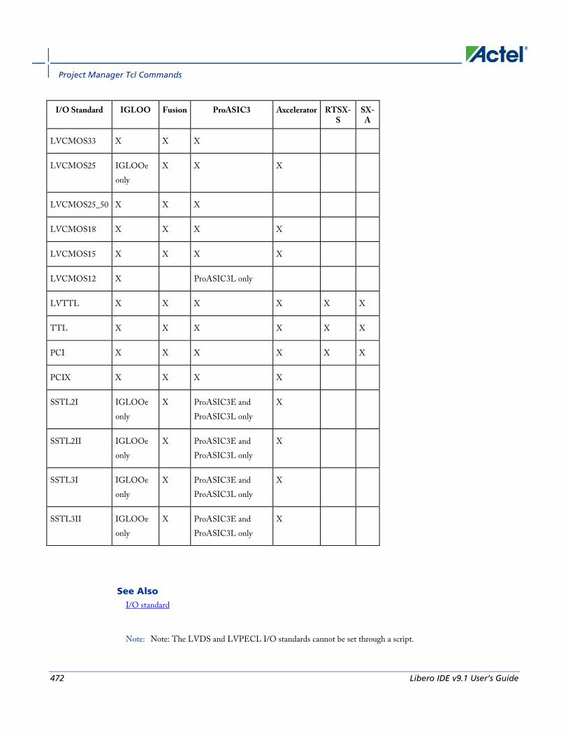
Project Manager Tcl Commands
472 Libero IDE v9.1 User’s Guide
I/O Standard IGLOO Fusion ProASIC3 Axcelerator RTSX-S
SX-A
LVCMOS33 X X X
LVCMOS25 IGLOOe only
X X X
LVCMOS25_50 X X X
LVCMOS18 X X X X
LVCMOS15 X X X X
LVCMOS12 X ProASIC3L only
LVTTL X X X X X X
TTL X X X X X X
PCI X X X X X X
PCIX X X X X
SSTL2I IGLOOe only
X ProASIC3E and ProASIC3L only
X
SSTL2II IGLOOe only
X ProASIC3E and ProASIC3L only
X
SSTL3I IGLOOe only
X ProASIC3E and ProASIC3L only
X
SSTL3II IGLOOe only
X ProASIC3E and ProASIC3L only
X
See Also I/O standard
Note: Note: The LVDS and LVPECL I/O standards cannot be set through a script.

pin_assign
Libero IDE v9.1 User’s Guide 473
-iothresh value
Sets the compatible threshold level for inputs and outputs. The default I/O threshold is based upon the I/O standard. You can set the I/O Threshold independently of the I/O specification in the PinEditor tool by selecting CUSTOM in the I/O Standard cell. The following table shows the acceptable values for the supported devices (SX-A, RTSX-S, and eX):
Value
Description
CMOS
RTSX-S devices only. An advanced integrated circuit (IC) manufacturing process technology for logic and memory, characterized by high integration, low cost, low power, and high performance. CMOS logic uses a combination of p-type and n-type metal-oxide-semiconductor field effect transistors (MOSFETs) to implement logic gates and other digital circuits found in computers, telecommunications, and signal processing equipment.
LVTTL
(Low-Voltage TTL) A general purpose standard (EIA/JESDSA) for 3.3V applications. It uses an LVTTL input buffer and a push-pull output buffer.
PCI A computer bus for attaching peripheral devices to a computer motherboard in a local bus. This standard supports both 33 MHz and 66 MHz PCI bus applications. It uses an LVTTL input buffer and a push-pull output buffer. With the aid of an external resistor, this I/O standard can be 5V-compliant for most families, excluding IGLOO, ProASIC3, SmartFusion and Fusion families.
Note: Note: The -iothresh attribute is also referred to as "Loading" in some families.
-slew value
Sets the output slew rate. Slew control affects only the falling edges. Rising edges are not affected. This attribute is only available for LVTTL, PCI, and PCI outputs. For LVTTL, it can either be high or low. For PCI and PCIX, it can only be set to high. The following table shows the acceptable values for the supported devices (IGLOO, ProASIC3, SmartFusion, Fusion, ProASICPLUS, ProASIC, Axcelerator, RTAX-S, eX, and SX-A):
Value
Description
high Sets the I/O slew to high
low Sets the I/O slew to low
-res_pull value
Allows you to include a weak resistor for either pull-up or pull-down of the input buffer. The following table shows the acceptable values for the supported devices (IGLOO, ProASIC3, SmartFusion, Fusion, ProASICPLUS, ProASIC, Axcelerator, RTAX-S, eX, and SX-A):
Project Manager Tcl Commands
474 Libero IDE v9.1 User’s Guide
Value
Description
up Includes a weak resistor for pull-up of the input buffer
down
Includes a weak resistor for pull-down of the input buffer
none
Does not include a weak resistor
-out_load value
Indicates the output-capacitance value based on the I/O standard selected. This option is not available in software. This attribute determines what Timer will use as the loading on the output pin and applies only to outputs. You can enter a capacitive load as an integral number of picofarads (pF). The default is 35pF. This attribute is available only for the following devices: ProASIC3, SmartFusion, Fusion, Axcelerator, SX-A, RTSX-S, and eX.
Supported Families The first syntax statement for pin_assign supports all families. The second one supports only IGLOO, ProASIC3, SmartFusion, Fusion, ProASICPLUS, ProASIC, Axcelerator, RTAX-S, eX, and SX-A.
Exceptions • None
Examples You must use pin_commit after the pin_assign command to save the changes to your design:
pin_assign -port usw0 -pin A2
pin_commit
pin_assign -port usw0 -iostd LVTTL -slew low -res_pull down
pin_commit
Note: Note: To use a name with special characters such as square brackets [ ], you must put the entire name between curly braces { } or put a slash character \ immediately before each square bracket as shown in the following examples.
Note: The following example shows a port name enclosed with curly braces:
Note: The next example shows each square bracket preceded by a slash:
pin_assign -port LFSR_OUT\[15\] -iostd lvttl -slew High
See Also pin_commit
pin_fix
pin_unassign

pin_commit
Libero IDE v9.1 User’s Guide 475
Tcl documentation conventions
pin_commit Saves the pin assignments to the design (.adb) file.
pin_commit
Note: Note: You can use this command for designs created with PinEditor in MVN and PinEditor (non-MVN).
Arguments • None
Supported Families All families
Exceptions • None
Examples To save pin assignments in your design, you must add the pin_commit command to the end of the script:
pin_commit
See Also pin_fix
pin_unfix
pin_assign
pin_unassign
Tcl documentation conventions
pin_fix Locks the pin assignment for the specified port, so the pins cannot be moved during place-and-route.
pin_fix -port portname
Note: Note: You can use this command for designs created with PinEditor in MVN and PinEditor (non-MVN).
Arguments -port portname
Specifies the name of the port to which the pin must be locked at its assigned location. Note: Note: You can assign only one pin to a port

Project Manager Tcl Commands
476 Libero IDE v9.1 User’s Guide
Supported Families All families
Description Fixed pins are locked pins. You cannot move locked pins during place-and-route.
Exceptions • None
Examples You must use pin_commit after the pin_fix command to save the changes to your design:
pin_fix –port clk
pin_commit
See Also pin_commit
pin_unfix
pin_assign
pin_unassign
Tcl documentation conventions
pin_fix_all Locks all the assigned pins on the device so they cannot be moved during place-and-route.
pin_fix_all
Note: Note: You can use this command for designs created with PinEditor in MVN and PinEditor (non-MVN).
Arguments • None
Supported Families All families
Description Fixed pins are locked pins. This command locks all the pins in your design. You cannot move locked pins during place-and-route.
Exceptions • None

pin_unassign
Libero IDE v9.1 User’s Guide 477
Example You must use pin_commit after the pin_fix_all command to save the changes to your design:
pin_fix_all
pin_commit
See Also pin_commit
pin_fix
pin_unfix
pin_assign
pin_unassign
Tcl documentation conventions
pin_unassign Unassigns the pin from the specified port. The unassigned pin location is then available for other ports. (Only one pin can be assigned to a port.)
pin_unassign -port portname
Note: Note: You can use this command for designs created with PinEditor in MVN and PinEditor (non-MVN).
Arguments -port portname
Specifies the name of the port for which the pin must be unassigned.
Supported Families All
Exceptions • None
Examples You must use pin_commit after the pin_assign command to save the changes to your design:
pin_unassign –port “clk”
pin_commit
See Also pin_commit
pin_fix
pin_fix_all
pin_unfix
pin_assign
pin_unassign

Project Manager Tcl Commands
478 Libero IDE v9.1 User’s Guide
Tcl documentation conventions
pin_unassign_all Unassigns all the pins from all the ports so that all pin locations are available for assignment.
pin_unassign_all
Note: Note: You can use this command for designs created with PinEditor in MVN and PinEditor (non-MVN).
Arguments • None
Supported Families All families
Exceptions • None
Examples You must use pin_commit after the pin_assign_all command to save the changes to your design:
pin_unassign_all
pin_commit
See Also pin_commit
pin_fix
pin_unfix
pin_assign
pin_unassign
Tcl documentation conventions
pin_unfix Unlocks the pins assigned to the specified port, so the pins can be moved during place-and-route.
pin_unfix -port portname
Note: Note: You can use this command for designs created with PinEditor in MVN and PinEditor (non-MVN).
Arguments -port portname
Specifies the name of the port containing pins to unlock.
remove_clock
Libero IDE v9.1 User’s Guide 479
Supported Families All families
Exceptions None
Examples You must use pin_commit command after the pin_unfix command to save the changes to your design:
pin_unfix –port rst
pin_commit
See Also pin_commit
pin_fix
pin_assign
pin_unassign
Tcl documentation conventions
remove_clock Removes the specified clock constraint from the current timing scenario.
remove_clock {-name clock_name| -id constraint_ID
Arguments -name clock_name
Specifies the name of the clock constraint to remove from the current scenario. You must specify either a clock name or an ID. -id constraint_ID
Specifies the ID of the clock constraint to remove from the current scenario. You must specify either an ID or a clock name that exists in the current scenario.
Supported Families IGLOO, ProASIC3, SmartFusion, Fusion, ProASICPLUS, ProASIC (for analysis), Axcelerator, RTAX-S,eX, and SX-A
Description Removes the specified clock constraint from the current scenario. If the specified name does not match a clock constraint in the current scenario, or if the specified ID does not refer to a clock constraint, this command fails.
Do not specify both the name and the ID.
Project Manager Tcl Commands
480 Libero IDE v9.1 User’s Guide
Exceptions • You cannot use wildcards when specifying a clock name.
Examples The following example removes the clock constraint named "my_user_clock":
remove_clock -name my_user_clock
The following example removes the clock constraint using its ID:
set clockId [create_clock –name my_user_clock –period 2]
remove_clock –id $clockId
See Also create_clock
Tcl Command Documentation Conventions
remove_clock_latency Removes a clock source latency from the specified clock and from all edges of the clock.
remove_clock_latency {-source clock_name_or_source |-id constraint_ID}
Arguments -source clock_name_or_source
Specifies either the clock name or source name of the clock constraint from which to remove the clock source latency. You must specify either a clock or source name or its constraint ID. -id constraint_ID
Specifies the ID of the clock constraint to remove from the current scenario. You must specify either a clock or source name or its constraint ID.
Supported Families IGLOO, ProASIC3, SmartFusion, Fusion, ProASICPLUS, ProASIC (for analysis), Axcelerator, RTAX-S,eX, and SX-A
Description Removes a clock source latency from the specified clock in the current scenario. If the specified source does not match a clock with a latency constraint in the current scenario, or if the specified ID does not refer to a clock with a latency constraint, this command fails.
Do not specify both the source and the ID.
Exceptions • You cannot use wildcards when specifying a clock name.

remove_clock_uncertainty
Libero IDE v9.1 User’s Guide 481
Examples The following example removes the clock source latency from the specified clock.
remove_clock_latency -source my_clock
See Also set_clock_latency
Tcl Command Documentation Conventions
remove_clock_uncertainty Removes a clock-to-clock uncertainty from the current timing scenario by specifying either its exact arguments or its ID.
remove_clock_uncertainty -from | -rise_from | -fall_from from_clock_list -to | -rise_to| -fall_to to_clock_list -setup {value} -hold {value}
remove_clock_uncertainty -id constraint_ID
Arguments -from
Specifies that the clock-to-clock uncertainty applies to both rising and falling edges of the source clock list. Only one of the -from, -rise_from, or -fall_from arguments can be specified for the constraint to be valid. -rise_from
Specifies that the clock-to-clock uncertainty applies only to rising edges of the source clock list. Only one of the -from, -rise_from, or -fall_from arguments can be specified for the constraint to be valid. -fall_from
Specifies that the clock-to-clock uncertainty applies only to falling edges of the source clock list. Only one of the -from, -rise_from, or -fall_from arguments can be specified for the constraint to be valid. from_clock_list
Specifies the list of clock names as the uncertainty source. -to
Specifies that the clock-to-clock uncertainty applies to both rising and falling edges of the destination clock list. Only one of the -to, -rise_to , or -fall_to arguments can be specified for the constraint to be valid. -rise_to
Specifies that the clock-to-clock uncertainty applies only to rising edges of the destination clock list. Only one of the -to, -rise_to , or -fall_to arguments can be specified for the constraint to be valid. -fall_to
Specifies that the clock-to-clock uncertainty applies only to falling edges of the destination clock list. Only one of the -to, -rise_to , or -fall_to arguments can be specified for the constraint to be valid. to_clock_list
Specifies the list of clock names as the uncertainty destination. -setup
Specifies that the uncertainty applies only to setup checks. If none or both -setup and -hold are present, the uncertainty applies to both setup and hold checks. -hold

Project Manager Tcl Commands
482 Libero IDE v9.1 User’s Guide
Specifies that the uncertainty applies only to hold checks. If none or both -setup and -hold are present, the uncertainty applies to both setup and hold checks. -id constraint_ID
Specifies the ID of the clock constraint to remove from the current scenario. You must specify either the exact parameters to set the constraint or its constraint ID.
Supported Families IGLOO, ProASIC3, SmartFusion, Fusion, ProASICPLUS, ProASIC (for analysis), Axcelerator, RTAX-S, eX (for analysis), SX-A (for analysis)
Description Removes a clock-to-clock uncertainty from the specified clock in the current scenario. If the specified arguments do not match clocks with an uncertainty constraint in the current scenario, or if the specified ID does not refer to a clock-to-clock uncertainty constraint, this command fails.
Do not specify both the exact arguments and the ID.
Exceptions • None
Examples remove_clock_uncertainty -from Clk1 -to Clk2
remove_clock_uncertainty -from Clk1 -fall_to { Clk2 Clk3 } -setup
remove_clock_uncertainty 4.3 -fall_from { Clk1 Clk2 } -rise_to *
remove_clock_uncertainty 0.1 -rise_from [ get_clocks { Clk1 Clk2 } ] -fall_to { Clk3 Clk4 } -setup
remove_clock_uncertainty 5 -rise_from Clk1 -to [ get_clocks {*} ]
remove_clock_uncertainty -id $clockId
See Also remove_clock
remove_generated_clock
set_clock_uncertainty
remove_disable_timing Removes a disable timing constraint by specifying its arguments, or its ID. If the arguments do not match a disable timing constraint, or if the ID does not refer to a disable timing constraint, the command fails.
remove_disable_timing -from value -to value name -id name
Arguments -from from_port
Specifies the starting port. The –from and –to arguments must either both be present or both omitted for the constraint to be valid.
remove_false_path
Libero IDE v9.1 User’s Guide 483
-to to_port
Specifies the ending port. The –from and –to arguments must either both be present or both omitted for the constraint to be valid. name
Specifies the cell name where the disable timing constraint will be removed. It is an error to supply both a cell name and a constraint ID, as they are mutually exclusive. No wildcards are allowed when specifying a clock name, either alone or in an accessor command1. -id name
Specifies the constraint name where the disable timing constraint will be removed. It is an error to supply both a cell name and a constraint ID, as they are mutually exclusive. No wildcards are allowed when specifying a clock name, either alone or in an accessor command1.
Supported Families IGLOO, ProASIC3, SmartFusion, Fusion, Axcelerator, and RTAX-S
Exceptions • None
Example remove_disable_timing -from port1 -to port2 -id new_constraint
remove_false_path Removes a false path from the current timing scenario by specifying either its exact arguments or its ID.
remove_false_path [-from from_list] [-to to_list] [-through through_list] [-id constraint_ID]
remove_false_path -id constraint_ID
Arguments -from from_list
Specifies a list of timing path starting points. A valid timing starting point is a clock, a primary input, an inout port, or a clock pin of a sequential cell. -through through_list
Specifies a list of pins, ports, cells, or nets through which the disabled paths must pass. -to to_list
Specifies a list of timing path ending points. A valid timing ending point is a clock, a primary output, an inout port, or a data pin of a sequential cell. -id constraint_ID
Specifies the ID of the false path constraint to remove from the current scenario. You must specify either the exact false path to remove or the constraint ID that refers to the false path constraint to remove.
Supported Families IGLOO, ProASIC3, SmartFusion, Fusion, ProASICPLUS, ProASIC (for analysis), Axcelerator, RTAX-S, eX (-through option), and SX-A (-through option)

Project Manager Tcl Commands
484 Libero IDE v9.1 User’s Guide
Description Removes a false path from the specified clock in the current scenario. If the arguments do not match a false path constraint in the current scenario, or if the specified ID does not refer to a false path constraint, this command fails.
Do not specify both the false path arguments and the constraint ID.
Exceptions • You cannot use wildcards when specifying a clock name, either alone or in an Accessor command such as
get_pins or get_ports.
Examples The following example specifies all false paths to remove:
remove_false_path -through U0/U1:Y
The following example removes the false path constraint using its id:
set fpId [set_false_path –from [get_clocks c*] –through {topx/reg/*} –to [get_ports out15] ]
remove_false_path –id $fpId
See Also set_false_path
Tcl Command Documentation Conventions
remove_generated_clock Removes the specified generated clock constraint from the current scenario.
remove_generated_clock {-name clock_name | -id constraint_ID }
Arguments -name clock_name
Specifies the name of the generated clock constraint to remove from the current scenario. You must specify either a clock name or an ID. -id constraint_ID
Specifies the ID of the generated clock constraint to remove from the current scenario. You must specify either an ID or a clock name that exists in the current scenario.
Supported Families IGLOO, ProASIC3, SmartFusion, Fusion, ProASICPLUS, ProASIC (for analysis), Axcelerator, RTAX-S,eX, and SX-A
remove_input_delay
Libero IDE v9.1 User’s Guide 485
Description Removes the specified generated clock constraint from the current scenario. If the specified name does not match a generated clock constraint in the current scenario, or if the specified ID does not refer to a generated clock constraint, this command fails.
Do not specify both the name and the ID.
Exceptions • You cannot use wildcards when specifying a generated clock name.
Examples The following example removes the generated clock constraint named "my_user_clock":
remove_generated_clock -name my_user_clock
See Also create_generated_clock
Tcl Command Documentation Conventions
remove_input_delay Removes an input delay a clock on a port by specifying both the clocks and port names or the ID of the input_delay constraint to remove.
remove_input_delay -clock clock_name port_pin_list
remove_input_delay -id constraint_ID
Arguments -clock clock_name
Specifies the clock name to which the specified input delay value is assigned. port_pin_list
Specifies the port names to which the specified input delay value is assigned. -id constraint_ID
Specifies the ID of the clock with the input_delay value to remove from the current scenario. You must specify either both a clock name and list of port names or the input_delay constraint ID .
Supported Families IGLOO, ProASIC3, SmartFusion, Fusion, ProASICPLUS, ProASIC, Axcelerator, RTAX-S, eX (for analysis), and SX-A (for analysis)
Project Manager Tcl Commands
486 Libero IDE v9.1 User’s Guide
Description Removes an input delay from the specified clocks and port in the current scenario. If the clocks and port names do not match an input delay constraint in the current scenario, or if the specified ID does not refer to an input delay constraint, this command fails.
Do not specify both the clock and port names and the constraint ID.
Exceptions • You cannot use wildcards when specifying a clock name, either alone or in an accessor command.
Examples The following example removes the input delay from CLK1 on port data1:
remove_input_delay -clock [get_clocks CLK1] [get_ports data1]
See Also set_input_delay
Tcl Command Documentation Conventions
remove_library Removes a VHDL library from your project.
remove_library -library name
Arguments -library name
Specifies the name of the library you wish to remove.
Supported Families All
Exceptions • None
Example Remove (delete) a library called 'my_lib'.
remove_library –library my_lib
See Also add_library
rename_library

remove_max_delay
Libero IDE v9.1 User’s Guide 487
remove_max_delay Removes a maximum delay constraint from the current timing scenario by specifying either its exact arguments or its ID.
remove_max_delay [-from from_list] [-to to_list] [-through through_list]
remove_max_delay -id constraint_ID
Arguments -from from_list
Specifies a list of timing path starting points. A valid timing starting point is a clock, a primary input, an inout port, or a clock pin of a sequential cell. -through through_list
Specifies a list of pins, ports, cells, or nets through which the disabled paths must pass. -to to_list
Specifies a list of timing path ending points. A valid timing ending point is a clock, a primary output, an inout port, or a data pin of a sequential cell. -id constraint_ID
Specifies the ID of the maximum delay constraint to remove from the current scenario. You must specify either the exact maximum delay arguments to remove or the constraint ID that refers to the maximum delay constraint to remove.
Supported Families IGLOO, ProASIC3, SmartFusion, Fusion, ProASICPLUS, ProASIC (for analysis), Axcelerator, RTAX-S, eX (-through option), and SX-A (-through option)
Description Removes a maximum delay value from the specified clock in the current scenario. If the arguments do not match a maximum delay constraint in the current scenario, or if the specified ID does not refer to a maximum delay constraint, this command fails.
Do not specify both the maximum delay arguments and the constraint ID.
Exceptions • You cannot use wildcards when specifying a clock name, either alone or in an Accessor command.
Examples The following example specifies a range of maximum delay constraints to remove:
remove_max_delay -through U0/U1:Y
See Also set_max_delay
Tcl Command Documentation Conventions

Project Manager Tcl Commands
488 Libero IDE v9.1 User’s Guide
remove_min_delay Removes a minimum delay constraint in the current timing scenario by specifying either its exact arguments or its ID.
remove_min_delay [-from from_list] [-to to_list] [-through through_list]
remove_min_delay -id constraint_ID
Arguments -from from_list
Specifies a list of timing path starting points. A valid timing starting point is a clock, a primary input, an inout port, or a clock pin of a sequential cell. -through through_list
Specifies a list of pins, ports, cells, or nets through which the disabled paths must pass. -toto_list
Specifies a list of timing path ending points. A valid timing ending point is a clock, a primary output, an inout port, or a data pin of a sequential cell. -id constraint_ID
Specifies the ID of the minimum delay constraint to remove from the current scenario. You must specify either the exact minimum delay arguments to remove or the constraint ID that refers to the minimum delay constraint to remove.
Supported Families IGLOO, ProASIC3, SmartFusion, Fusion, ProASICPLUS, ProASIC (for analysis), Axcelerator, RTAX-S, eX (-through option), and SX-A (-through option)
Description Removes a minimum delay value from the specified clock in the current scenario. If the arguments do not match a minimum delay constraint in the current scenario, or if the specified ID does not refer to a minimum delay constraint, this command fails.
Do not specify both the minimum delay arguments and the constraint ID.
Exceptions • You cannot use wildcards when specifying a clock name, either alone or in an accessor command.
Examples The following example specifies a range of minimum delay constraints to remove:
remove_min_delay -through U0/U1:Y
See Also set_min_delay
Tcl Command Documentation Conventions

remove_multicycle_path
Libero IDE v9.1 User’s Guide 489
remove_multicycle_path Removes a multicycle path constraint in the current timing scenario by specifying either its exact arguments or its ID.
remove_multicycle_path [-from from_list] [-to to_list] [-through through_list]
remove multicycle_path -id constraint_ID
Arguments -from from_list
Specifies a list of timing path starting points. A valid timing starting point is a clock, a primary input, an inout port, or a clock pin of a sequential cell. -through through_list
Specifies a list of pins, ports, cells, or nets through which the disabled paths must pass. -toto_list
Specifies a list of timing path ending points. A valid timing ending point is a clock, a primary output, an inout port, or a data pin of a sequential cell. -id constraint_ID
Specifies the ID of the multicycle path constraint to remove from the current scenario. You must specify either the exact multicycle path arguments to remove or the constraint ID that refers to the multicycle path constraint to remove.
Supported Families IGLOO, ProASIC3, SmartFusion, Fusion, ProASICPLUS, ProASIC (for analysis), Axcelerator, RTAX-S, eX (for analysis), SX-A (for analysis)
Description Removes a multicycle path from the specified clock in the current scenario. If the arguments do not match a multicycle path constraint in the current scenario, or if the specified ID does not refer to a multicycle path constraint, this command fails.
Do not specify both the multicycle path arguments and the constraint ID.
Exceptions • You cannot use wildcards when specifying a clock name, either alone or in an accessor command.
Examples The following example removes all paths between reg1 and reg2 to 3 cycles for setup check.
remove_multicycle_path -from [get_pins {reg1}] –to [get_pins {reg2}]
See Also set_multicycle_path
Tcl Command Documentation Conventions

Project Manager Tcl Commands
490 Libero IDE v9.1 User’s Guide
remove_output_delay Removes an ouput delay by specifying both the clocks and port names or the ID of the output_delay constraint to remove.
remove_output_delay -clock clock_name port_pin_list
remove_output_delay -id constraint_ID
Arguments -clock clock_name
Specifies the clock name to which the specified output delay value is assigned. port_pin_list
Specifies the port names to which the specified output delay value is assigned. -id constraint_ID
Specifies the ID of the clock with the output_delay value to remove from the current scenario. You must specify either both a clock name and list of port names or the output_delay constraint ID .
Supported Families IGLOO, ProASIC3, SmartFusion, Fusion, ProASICPLUS, ProASIC (for analysis), Axcelerator, RTAX-S, eX (for analysis), SX-A (for analysis)
Description Removes an output delay from the specified clocks and port in the current scenario. If the clocks and port names do not match an output delay constraint in the current scenario, or if the specified ID does not refer to an output delay constraint, this command fails.
Do not specify both the clock and port names and the constraint ID.
Exceptions • You cannot use wildcards when specifying a clock name, either alone or in an accessor command.
Examples The following example removes the output delay from CLK1 on port out1:
remove_output_delay -clock [get_clocks CLK1] [get_ports out1]
See Also set_output_delay
Tcl Command Documentation Conventions
rename_library Renames a VHDL library in your project.
rename_scenario
Libero IDE v9.1 User’s Guide 491
rename_library -library name -name name
Arguments -library name
Identifies the current name of the library that you wish to rename. -name name
Specifies the new name of the library.
Supported Families All
Exceptions • None
Example Rename a library from 'my_lib' to 'test_lib1'
rename_library –library my_lib -name test_lib1
See Also add_library
remove_library
rename_scenario Renames the specified timing scenario with the new name provided. You must provide a unique new name (that is, it cannot already be used by another timing scenario).
rename_scenario oldname -new newname
Arguments oldname
Specifies the current name of the timing scenario. -new newname
Specifies the new name to give to the timing scenario.
Supported Families IGLOO, ProASIC3, SmartFusion, Fusion, Axcelerator, and RTAX-S
Description This command changes the name of the timing scenario in the list of scenarios.

Project Manager Tcl Commands
492 Libero IDE v9.1 User’s Guide
Example rename_scenario scenario_A -new scenario_B
See Also create_scenario
delete_scenario
Tcl documentation conventions
report The report command provides you with frequently-used information in a convenient format.
You can generate several different types of reports using this command, including:
• report (Status)
• report (Timing) using Timer; for the SX, MX, 3200DX and ACT families
• report (Timing violations) using Timer; for the SX, MX, 3200DX and ACT families
• report (Timing) using SmartTime; for IGLOO, ProASIC3, SmartFusion, Fusion, ProASICPLUS, ProASIC, Axcelerator, eX, and SX-A families
• report (Timing violations) using SmartTime; for IGLOO, ProASIC3, SmartFusion, Fusion, ProASICPLUS, ProASIC, Axcelerator, eX, and SX-A families
• report (Pin)
• report (Flip-flop)
• report (I/O Bank)
• report (Global Usage)
• report (Power)
report (Bottleneck) using SmartTime Creates a bottleneck report.
report -type bottleneck [-cost_type {value} ] [-use_slack_threshold{value} ] [-slack_threshold {value} ] [-set_name {value} ] [-clock clock_id -set_type value ] [-source_clock clock_id -sink_clock clock_id] [-source {pin_list} ] [-sink {pin_list} ] [-max_instances {value} ] [-max_paths {value} ] [-max_parallel_paths {value} ] [-analysis_type {value} ]

report (Bottleneck) using SmartTime
Libero IDE v9.1 User’s Guide 493
{filename} \ [−format value]
Arguments -cost_type value
Specifies the type of bottleneck cost. The default option is path_count.
Value Description
path_count Instances with the greatest number of path violations will have the highest bottleneck cost
path_cost Instances with the largest combined timing violations will have the highest bottleneck cost
-use_slack_threshold value
Specifies whether to consider the slack threshold when computing the bottlenecks in the report.
Value Description
yes Includes slack threshold in the bottleneck report
no Excludes slack threshold in the bottleneck report
-slack_threshold value
Specifies that paths whose slack is larger than this given threshold will be considered. Only instances that lie on these violating paths are reported. The default option is 0. -set_name value
Displays the bottleneck information for the named set. You can either use this option or use both –clock and –type. This option allows pruning based on a given set. Only paths that lie within the named set will be considered towards bottleneck. -clock value
This option allows pruning based on a given clock domain. Only instances that lie on these violating paths are reported. -set_type value
This option can only be used in combination with the –clock option, and not by itself. The options allow to filter which type of paths should be considered towards the bottleneck.
Value Description
reg_to_reg Paths between registers in the design
async_to_reg Paths from asynchronous pins to registers
reg_to_async Paths from registers to asynchronous pins

Project Manager Tcl Commands
494 Libero IDE v9.1 User’s Guide
Value Description
external_recovery The set of paths from inputs to asynchronous pins
external_removal The set of paths from inputs to asynchronous pins
external_setup Paths from input ports to registers
external_hold Paths from input ports to registers
clock_to_out Paths from registers to output ports
-source_clock clock_id
Reports only bottleneck instances that lie on violating timing paths of the inter-clock domain that starts at the source clock specified by this option. This option can only be used in combination with -sink_clock, and not by itself. -sink_clock clock_id
Reports only bottleneck instances that lie on violating timing paths of the inter-clock domain that ends at the sink clock specified by this option. This option can only be used in combination with -source_clock, and not by itself. -source value
Reports only instances that lie on violating paths that start at locations specified by this option. -sink value
Reports only instances that lie on violating paths that end at locations specified by this option. -max_instances value
Specifies the maximum number of instances to be reported. Defaults to 10. -max_paths value
Specifies the maximum number of paths to be considered per path set type. Allowed values are 1 to 2000000. Defaults to 100. -max_parallel_paths value
Specifies the maximum number of paths allowed per end point pair. Only instances that lie on these violating paths are reported. Defaults to 1 (No parallel paths). -analysis_type value
Specifies the analysis types (max or min) under which the violations are reported. Defaults to max analysis.
Value Description
max_delay Sets the analysis type to maximum delay
min_delay Sets the analysis type to minimum delay
−format value
Specifies the output format of the generated report.
Value Description
text Generates a text report; text is the default value

report (Cycle Accurate Power Report)
Libero IDE v9.1 User’s Guide 495
Value Description
csv Generates the report in a comma-separated value format that you can import into a spreadsheet
filename Specifies the name and destination of the bottleneck report.
Supported Families IGLOO, ProASIC3, SmartFusion, Fusion, ProASICPLUS, ProASIC, Axcelerator, and SX-A
Exceptions None
Examples The following example generates a bottleneck report named bottleneck.txt.
report -type bottleneck -cost-type path_count -slack_threshold 0 -set_name set1 -max_cells 10 -max_paths 10 -max_parallel_paths 10 -analysis_type max -format text bottleneck.txt
See Also Tcl documentation conventions
report (Cycle Accurate Power Report) Creates a cycle accurate power report, which reports a power waveform with one power value per clock period or half-period instead of an average power for the whole simulation.
report -type power_peak_analyzer \ [-vcd_file {path}] \ [-style {value}] \ [-partial_parse {value}] \ [-start_time {value}] \ [-end_time {value}] \ [-auto_detect_top_level_name {value}] \ [-top_level_name {name}] \ [-glitch_filtering {value}] \ [-glitch_threshold {value}] \ [-auto_detect_sampling_period {value}] \ [-sampling_clock { }] \ [-sampling_rate_per_period {value}] \ [-sampling_offset {value}] \ [-sampling_period {value}] \ [-use_only_local_extrema {value}] \ [-use_power_threshold {value}] \ [-power_threshold {value}] \

Project Manager Tcl Commands
496 Libero IDE v9.1 User’s Guide
[-opmode {value}] \ {filename}
Arguments -type power_peak_analyzer
Specifies the type of report to generate is a cycle accurate power report. -vcd_file {path}
Specifies the path to the *.vcd file that you want to import. -style {value}
Specifies the format in which the report will be exported. The following table shows the acceptable values for this argument:
Value Description
Text The report will be exported as Text file
CSV The report will be exported as CSV file
-partial_parse {value}
Specifies whether to partially parse the *.vcd file. The following table shows the acceptable values for this argument:
Value Description
true Partially parses the *.vcd file
false Does not partially parse the *.vcd file
-start_time {value}
This option is available only if -partially_parse is set to true. Specifies the start time (in ns) to partially parse the *.vcd file. -end_time {value}
This option is available only if -partially_parse is set to true. Specifies the end time (in ns) to partially parse the *.vcd file. -auto_detect_top_level_name {value}
Specifies whether to automatically detect the top-level name. The following table shows the acceptable values for this argument:
Value Description
true Automatically detects the top-level name
false Does not automatically detect the top-level name
-top_level_name {name}
Specifies the top-level name.

report (Cycle Accurate Power Report)
Libero IDE v9.1 User’s Guide 497
-glitch_filtering {value}
Specifies whether to use glitch filtering. The following table shows the acceptable values for this argument:
Value Description
true Glitch filtering is on
auto Enables automatic glitch filtering. This option will ignore any value specified in -glitch_threshold
false Glitch filtering is off
-glitch_threshold {value}
This option is only available when -glitch_filtering is set to true. Specifies the glitch filtering value (in ps). -power_summary {value}
Specifies whether to include the power summary, which shows the static and dynamic values in the report. The following table shows the acceptable values for this argument:
Value Description
true Includes the power summary in the report
false Does not include the power summary in the report
-auto_detect_sampling_period {value}
Specifies whether to automatically detect the sampling period. The following table shows the acceptable values for this argument:
Value Description
true Automatically detects the sampling period
false Does not automatically detect the sampling period
-sampling_clock {}
Specifies the sampling clock. -sampling_rate_per_period {value}
Specifies whether to set the sampling rate per period. The following table shows the acceptable values for this argument:
Value Description
true Specifies the sampling rate per period
false Specifies the sampling rate per half period
Project Manager Tcl Commands
498 Libero IDE v9.1 User’s Guide
-sampling_offset {value}
Specifies the offset used to calculate the sampling offset (in ps). -sampling_period {value}
Specifies the offset used to calculate the sampling period (in ps). -use_only_local_extrema {value}
Specifies whether to limit the history size by keeping only local extrema. The following table shows the acceptable values for this argument:
Value Description
true Limits the history size by keeping only local extrema
false Does not limit the history size by keeping only local extrema
-use_power_threshold {value}
Specifies whether to limit the history size by setting a power threshold. The following table shows the acceptable values for this argument:
Value Description
true Limits the history size by setting a power threshold
false Does not limit the history size by setting a power threshold
-power_threshold {value}
Sets the power threshold value. -opmode {value}
Use this option to specify the mode from which the operating conditions are extracted to generate the report. {filename}
Specifies the name of the report.
Supported Families IGLOO, ProASIC3, SmartFusion, Fusion, ProASICPLUS, ProASIC, and Axcelerator
Notes • None
Exceptions • None
Examples This example generates a cycle accurate power report named report_power_cycle_based.txt.

report (Datasheet) using SmartTime
Libero IDE v9.1 User’s Guide 499
report -type "power_cycle_based" -vcd_file "D:/FPU/mul.vcd" -style "Text" -partial_parse "TRUE" -start_time "0.05" -end_time "1.00" -auto_detect_top_level_name "TRUE" -glitch_filtering "FALSE" -glitch_threshold "100" -auto_detect_sampling_period "TRUE" -sampling_clock "clk" -sampling_rate_per_period "TRUE" -sampling_offset "0.00" -sampling_period "10000.00" -use_only_local_extrema "TRUE" -use_power_threshold "TRUE" -power_threshold "0.00" -opmode "Active" \ {D:/FPU/report_power_cycle_based.txt}
report (Datasheet) using SmartTime Creates a datasheet report.
report -type datasheet filename \ [−format value]
Arguments filename
Specifies the name and destination of the datasheet report. −format value
Specifies the output format of the generated the report.
Value Description
text Generates a text report; text is the default value
csv Generates the report in a comma-separated value format which you can import into a spreadsheet
Supported Families IGLOO, ProASIC3, SmartFusion, Fusion, ProASICPLUS, ProASIC, Axcelerator, eX, and SX-A
Exceptions None
Examples The following example generates a datasheet report named datasheet.txt.
report -type datasheet -format Text datasheet.txt
See Also Tcl documentation conventions
report (Timing) using SmartTime
report (Timing violations) using SmartTime

Project Manager Tcl Commands
500 Libero IDE v9.1 User’s Guide
report (Power Scenario) Creates a scenario power report for a previously defined scenario. It includes information about the global device and SmartPower preferences selection, and the average power consumption and the excepted battery life for this sequence.
report -type power_scenario \ [-powerunit {value}] \ [-frequnit {value}] \ [-opcond {value}] \ [-toggle {value}] \ [-scenario {value}] \ [-style {value}] \ [-battery_life {value}] \ [-battery_capacity {value}] \ [-rail_breakdown {value}] \ [-type_breakdown {value}] \ [-mode_breakdown {value}] \ [-opcond_summary {value}] \ {filename}
Arguments -type power_scenario
Specifies the type of report to generate is a scenario power report. -powerunit {value}
Specifies the unit in which power is set. The following table shows the acceptable values for this argument:
Value Description
W The power unit is set to watts
mW The power unit is set to milliwatts
uW The power unit is set to microwatts
-frequnit {value}
Specifies the unit in which frequency is set. The following table shows the acceptable values for this argument:
Value Description
Hz The frequency unit is set to hertz
kHz The frequency unit is set to kilohertz
MHz The frequency unit is set to megahertz
-toggle {value}
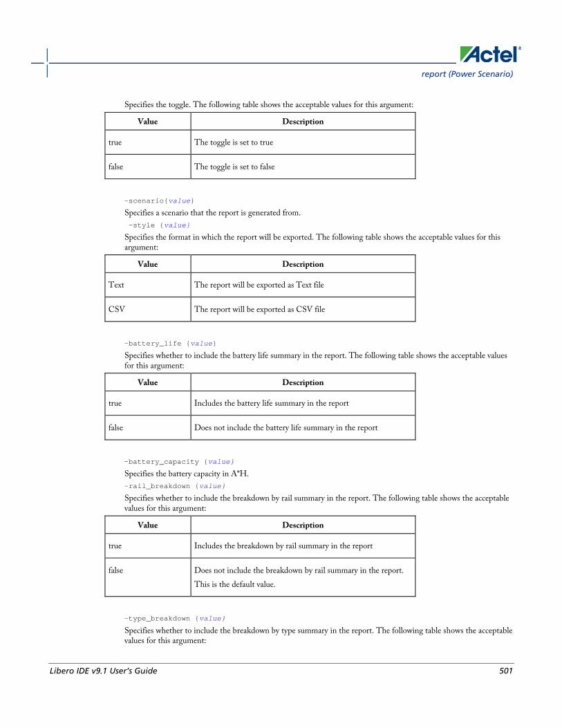
report (Power Scenario)
Libero IDE v9.1 User’s Guide 501
Specifies the toggle. The following table shows the acceptable values for this argument:
Value Description
true The toggle is set to true
false The toggle is set to false
-scenario{value}
Specifies a scenario that the report is generated from. -style {value}
Specifies the format in which the report will be exported. The following table shows the acceptable values for this argument:
Value Description
Text The report will be exported as Text file
CSV The report will be exported as CSV file
-battery_life {value}
Specifies whether to include the battery life summary in the report. The following table shows the acceptable values for this argument:
Value Description
true Includes the battery life summary in the report
false Does not include the battery life summary in the report
-battery_capacity {value}
Specifies the battery capacity in A*H. -rail_breakdown {value}
Specifies whether to include the breakdown by rail summary in the report. The following table shows the acceptable values for this argument:
Value Description
true Includes the breakdown by rail summary in the report
false Does not include the breakdown by rail summary in the report. This is the default value.
-type_breakdown {value}
Specifies whether to include the breakdown by type summary in the report. The following table shows the acceptable values for this argument:

Project Manager Tcl Commands
502 Libero IDE v9.1 User’s Guide
Value Description
true Includes the breakdown by type summary in the report
false Does not include the breakdown by type summary in the report. This is the default value.
-mode_breakdown {value}
Specifies whether to include a breakdown by mode in the report. The following table shows the acceptable values for this argument:
Value Description
true Includes the breakdown by mode in the report
false Does not include the breakdown by mode in the report. This is the default value.
-opcond_summary {value}
Specifies whether to include the operating conditions summary in the report. The following table shows the acceptable values for this argument:
Value Description
true Includes the operating conditions summary in the report
false Does not include the operating conditions summary in the report
{filename.rpt}
Specifies the name of the report.
Supported Families IGLOO, ProASIC3, SmartFusion, Fusion, ProASICPLUS, ProASIC, and Axcelerator
Notes • Flash*Freeze, Sleep, and Shutdown are available only for certain families and devices.
• Worst and Best are available only for certain families and devices.
Exceptions • None

report (Timing) using SmartTime
Libero IDE v9.1 User’s Guide 503
Examples This example generates a scenario power report named report.txt for my_scenario
report -type power_scenario -scenario my_scenario -rail_breakdown true -type_breakdown true -mode_breakdown true -style text -battery_capacity 10 report.txt
See Also Scenario Power Report
report (Timing) using SmartTime Creates a timing report.
report -type timing filename\ [−print_summary value]\ [−analysis value]\ [−use_slack_threshold value]\ [−slack_threshold value]\ [−print_paths value]\ [−max_paths value]\ [−max_expanded_paths value]\ [−include_user_sets value]\ [−include_pin_to_pin value]\ [-include_clock_domains value]\ [−select_clock_domains value]\ [−clock_domain clock_domain_list] [−format value]
Arguments filename
Specifies the name and destination of the timing report. -type timing
Specifies the type of report to generate. −print_summary value
Specifies whether to print the summary section in the timing report.
Value Description
yes Includes summary section in the timing report (the default value).
no Excludes summary section in the timing report
−analysis value
Specifies whether the report will consider minimum analysis or maximum analysis.
Value Description

Project Manager Tcl Commands
504 Libero IDE v9.1 User’s Guide
Value Description
min Timing report considers minimum analysis
max Timing report considers maximum analysis (the default value)
−use_slack_threshold value
Specifies whether the report will consider slack threshold.
Value Description
yes Includes slack threshold in the timing report.
no Excludes slack threshold in the timing report (the default value)
−slack_threshold value
Specifies the threshold to consider when reporting path slacks. This is a floating-point number in nanoseconds (ns). By default, there is no threshold (all slacks are reported). −print_paths value
Specifies whether the path section (clock domains and in-to-out paths) will be printed in the timing report.
Value Description
yes Includes path section in the timing report (the default value)
no Excludes path sections from the timing report
−max_paths value
Defines the maximum number of paths to display for each set. This is a positive integer value greater than zero. The default is 5. −max_expanded_paths value
Defines the number of paths to expand per set. This is a positive integer value greater than zero. The default is 1. −include_user_sets value
Defines whether to include the user defined sets in the timing report.
Value Description
yes Includes user defined sets in the timing report (the default value)
no Excludes user defined sets from the timing report
−include_pin_to_pin value
Specifies whether to show pin-to-pin paths in the timing report.
Value Description
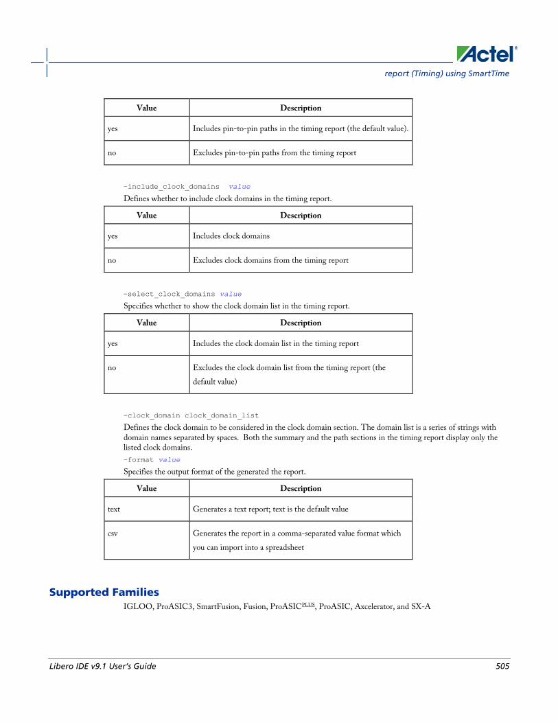
report (Timing) using SmartTime
Libero IDE v9.1 User’s Guide 505
Value Description
yes Includes pin-to-pin paths in the timing report (the default value).
no Excludes pin-to-pin paths from the timing report
−include_clock_domains value
Defines whether to include clock domains in the timing report.
Value Description
yes Includes clock domains
no Excludes clock domains from the timing report
−select_clock_domains value
Specifies whether to show the clock domain list in the timing report.
Value Description
yes Includes the clock domain list in the timing report
no Excludes the clock domain list from the timing report (the default value)
−clock_domain clock_domain_list
Defines the clock domain to be considered in the clock domain section. The domain list is a series of strings with domain names separated by spaces. Both the summary and the path sections in the timing report display only the listed clock domains. −format value
Specifies the output format of the generated the report.
Value Description
text Generates a text report; text is the default value
csv Generates the report in a comma-separated value format which you can import into a spreadsheet
Supported Families IGLOO, ProASIC3, SmartFusion, Fusion, ProASICPLUS, ProASIC, Axcelerator, and SX-A
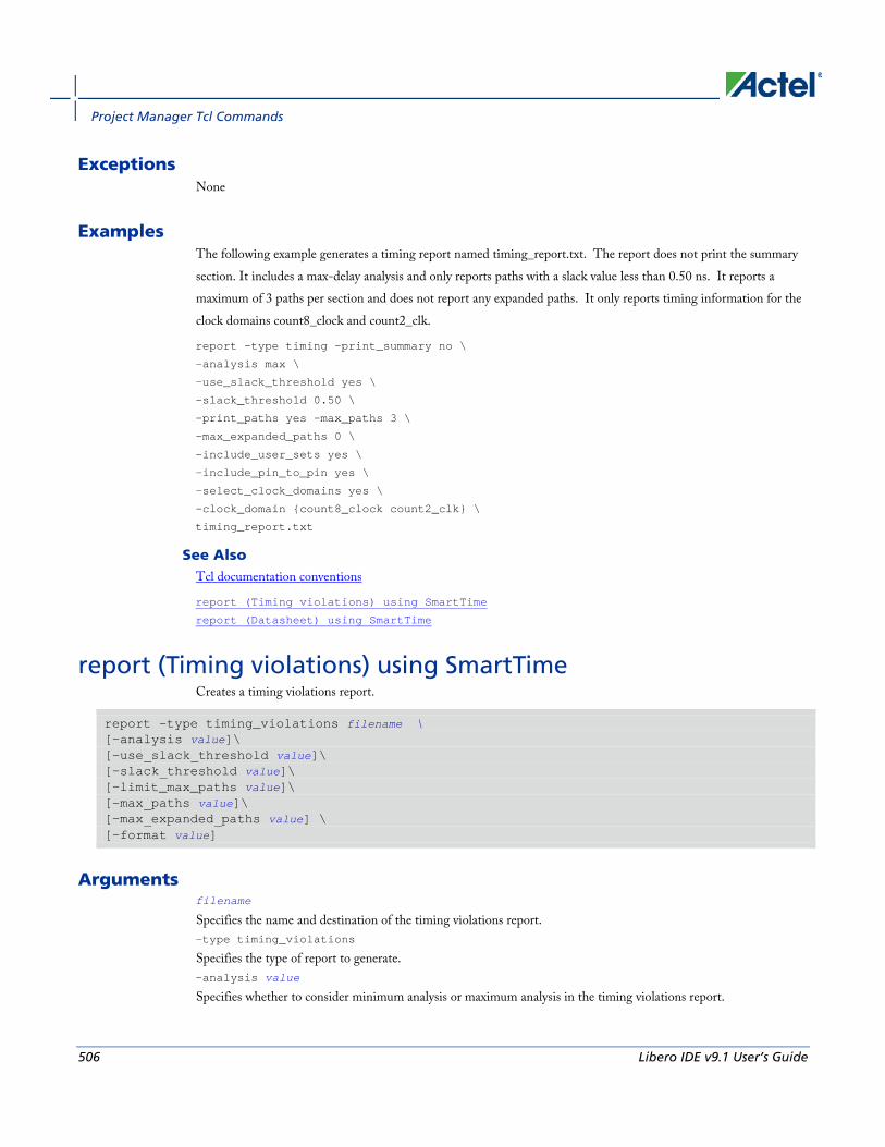
Project Manager Tcl Commands
506 Libero IDE v9.1 User’s Guide
Exceptions None
Examples The following example generates a timing report named timing_report.txt. The report does not print the summary section. It includes a max-delay analysis and only reports paths with a slack value less than 0.50 ns. It reports a maximum of 3 paths per section and does not report any expanded paths. It only reports timing information for the clock domains count8_clock and count2_clk.
report -type timing -print_summary no \
-analysis max \
-use_slack_threshold yes \
-slack_threshold 0.50 \
-print_paths yes -max_paths 3 \
-max_expanded_paths 0 \
-include_user_sets yes \
-include_pin_to_pin yes \
-select_clock_domains yes \
-clock_domain {count8_clock count2_clk} \
timing_report.txt
See Also Tcl documentation conventions
report (Timing violations) using SmartTime
report (Datasheet) using SmartTime
report (Timing violations) using SmartTime Creates a timing violations report.
report -type timing_violations filename \ [−analysis value]\ [−use_slack_threshold value]\ [−slack_threshold value]\ [–limit_max_paths value]\ [−max_paths value]\ [−max_expanded_paths value] \ [−format value]
Arguments filename
Specifies the name and destination of the timing violations report. -type timing_violations
Specifies the type of report to generate. −analysis value
Specifies whether to consider minimum analysis or maximum analysis in the timing violations report.

report (Timing violations) using SmartTime
Libero IDE v9.1 User’s Guide 507
Value Description
min Timing report considers minimum analysis
max Timing report considers maximum analysis (the default value)
−use_slack_threshold value
Specifies whether to consider the slack threshold in the timing violations report.
Value Description
yes Includes slack threshold in the timing violations report
no Excludes slack threshold in the timing violations report (the default value)
−slack_threshold value
Specifies the threshold to consider when reporting path slacks. This value is a floating-point number in nanoseconds (ns). By default, there is no threshold (all slacks reported). –limit_max_paths value
Specifies if the paths are limited by the number of paths.
Value Description
yes Limits the maximum number of paths to report
no Specifies that there is no limit to the number of paths to report (the default value)
−max_paths value
Specifies the maximum number of paths to display for each set. This value is a positive integer value greater than zero. Default is 100. −max_expanded_paths value
Specifies the number of paths to expand per set. This value is a positive integer value greater than zero. The default is 0. −format value
Specifies the output format of the generated report.
Value Description
text Generates a text report; text is the default value
csv Generates the report in a comma-separated value format which you can import into a spreadsheet

Project Manager Tcl Commands
508 Libero IDE v9.1 User’s Guide
Supported Families IGLOO, ProASIC3, SmartFusion, Fusion, ProASICPLUS, ProASIC, Axcelerator, and SX-A
Exceptions None
Examples The following example generates a timing violations report named timg_viol.txt. The report considers an analysis using maximum delays and does not filter paths based on slack threshold. It reports 2 paths per section and 1 expanded path per section.
report -type timing_violations \
-analysis max -use_slack_threshold no \
-limit_max_paths -yes \
-max_paths 2 \
-max_expanded_paths 1 \
timg_viol.txt
See Also Tcl documentation conventions
report (Timing) using SmartTime
report (Datasheet) using SmartTime
save_design The save_design command saves the current design in Designer to a file. If filename is not a complete path name, the ADB file is written into the current working directory.
save_design filename
Arguments The design is written to a file denoted by the variable filename as an ADB file.
Supported Families All
Exceptions None

set_clock_latency
Libero IDE v9.1 User’s Guide 509
Example Example 1: Saves the design to a file “test.adb” in the current folder.
save_design {test.adb}
Example 2: Save design and check if it saved successfully.
set designFile {d:/test/my_design.adb}
if { [catch { save_design $designFile }] {
Puts “Failed to save design”
# Handle Failure
} else {
puts “Design saved successfully”
# Proceed to make further changes
}
See Also close_design
new_design
open_design
set_clock_latency Defines the delay between an external clock source and the definition pin of a clock within SmartTime.
set_clock_latency -source [-rise][-fall][-early][-late] delay clock
Arguments -source
Specifies the source latency on a clock pin, potentially only on certain edges of the clock. -rise
Specifies the edge for which this constraint will apply. If neither or both rise are passed, the same latency is applied to both edges. -fall
Specifies the edge for which this constraint will apply. If neither or both rise are passed, the same latency is applied to both edges. -invert
Specifies that the generated clock waveform is inverted with respect to the reference clock. -late
Optional. Specifies that the latency is late bound on the latency. The appropriate bound is used to provide the most pessimistic timing scenario. However, if the value of "-late" is less than the value of "-early", optimistic timing takes place which could result in incorrect analysis. If neither or both "-early" and "-late" are provided, the same latency is used for both bounds, which results in the latency having no effect for single clock domain setup and hold checks. -early
Optional. Specifies that the latency is early bound on the latency. The appropriate bound is used to provide the most pessimistic timing scenario. However, if the value of "-late" is less than the value of "-early", optimistic timing takes place which could result in incorrect analysis. If neither or both "-early" and "-late" are provided, the same latency is used for both bounds, which results in the latency having no effect for single clock domain setup and hold checks. delay

Project Manager Tcl Commands
510 Libero IDE v9.1 User’s Guide
Specifies the latency value for the constraint. clock
Specifies the clock to which the constraint is applied. This clock must be constrained.
Supported Families IGLOO, ProASIC3, SmartFusion, Fusion, ProASICPLUS, ProASIC (for analysis), Axcelerator, RTAX-S,eX, and SX-A
Description Clock source latency defines the delay between an external clock source and the definition pin of a clock within SmartTime. It behaves much like an input delay constraint. You can specify both an "early" delay and a"late" delay for this latency, providing an uncertainty which SmartTime propagates through its calculations. Rising and falling edges of the same clock can have different latencies. If only one value is provided for the clock source latency, it is taken as the exact latency value, for both rising and falling edges.
Exceptions • None
Examples The following example sets an early clock source latency of 0.4 on the rising edge of main_clock. It also sets a clock source latency of 1.2, for both the early and late values of the falling edge of main_clock. The late value for the clock source latency for the falling edge of main_clock remains undefined.
set_clock_latency –source –rise –early 0.4 { main_clock }
set_clock_latency –source –fall 1.2 { main_clock }
See Also create_clock
create_generated_clock
Tcl Command Documentation Conventions
set_clock_uncertainty Specifies a clock-to-clock uncertainty between two clocks (from and to) and returns the ID of the created constraint if the command succeeded.
set_clock_uncertainty uncertainty -from | -rise_from | -fall_from from_clock_list -to | -rise_to | -fall_to to_clock_list -setup {value} -hold {value}
Arguments uncertainty
Specifies the time in nanoseconds that represents the amount of variation between two clock edges.

set_clock_uncertainty
Libero IDE v9.1 User’s Guide 511
-from
Specifies that the clock-to-clock uncertainty applies to both rising and falling edges of the source clock list. Only one of the -from, -rise_from, or -fall_from arguments can be specified for the constraint to be valid. -rise_from
Specifies that the clock-to-clock uncertainty applies only to rising edges of the source clock list. Only one of the -from, -rise_from, or -fall_from arguments can be specified for the constraint to be valid. -fall_from
Specifies that the clock-to-clock uncertainty applies only to falling edges of the source clock list. Only one of the -from, -rise_from, or -fall_from arguments can be specified for the constraint to be valid. from_clock_list
Specifies the list of clock names as the uncertainty source. -to
Specifies that the clock-to-clock uncertainty applies to both rising and falling edges of the destination clock list. Only one of the -to, -rise_to , or -fall_to arguments can be specified for the constraint to be valid. -rise_to
Specifies that the clock-to-clock uncertainty applies only to rising edges of the destination clock list. Only one of the -to, -rise_to , or -fall_to arguments can be specified for the constraint to be valid. -fall_to
Specifies that the clock-to-clock uncertainty applies only to falling edges of the destination clock list. Only one of the -to, -rise_to , or -fall_to arguments can be specified for the constraint to be valid. to_clock_list
Specifies the list of clock names as the uncertainty destination. -setup
Specifies that the uncertainty applies only to setup checks. If none or both -setup and -hold are present, the uncertainty applies to both setup and hold checks. -hold
Specifies that the uncertainty applies only to hold checks. If none or both -setup and -hold are present, the uncertainty applies to both setup and hold checks.
Supported Families IGLOO, ProASIC3, SmartFusion, Fusion, ProASICPLUS, ProASIC (for analysis), Axcelerator, RTAX-S, eX (for analysis), SX-A (for analysis)
Description The set_clock_uncertainty command sets the timing uncertainty between two clock waveforms or maximum clock skew. Timing between clocks have no uncertainty unless you specify it.
Exceptions • None
Examples set_clock_uncertainty 10 -from Clk1 -to Clk2
set_clock_uncertainty 0 -from Clk1 -fall_to { Clk2 Clk3 } -setup
set_clock_uncertainty 4.3 -fall_from { Clk1 Clk2 } -rise_to *

Project Manager Tcl Commands
512 Libero IDE v9.1 User’s Guide
set_clock_uncertainty 0.1 -rise_from [ get_clocks { Clk1 Clk2 } ] -fall_to { Clk3 Clk4 } -setup
set_clock_uncertainty 5 -rise_from Clk1 -to [ get_clocks {*} ]
See Also create_clock
create_generated_clock
remove_clock_uncertainty
set_current_scenario Specifies the timing scenario for the Timing Analyzer to use. All commands that follow this command will apply to the specified timing scenario.
set_current_scenario name
Arguments name
Specifies the name of the timing scenario to which to apply all commands from this point on.
Supported Families IGLOO, ProASIC3, SmartFusion, Fusion, Axcelerator, and RTAX-S
Description A timing scenario is a set of timing constraints used with a design. If the specified scenario is already the current one, this command has no effect.
After setting the current scenario, constraints can be listed, added, or removed, the checker can be invoked on the set of constraints, and so on.
This command uses the specified timing scenario to compute timing analysis.
Exceptions • None
Example set_current_scenario scenario_A
See Also get_current_scenario
Tcl Command Documentation Conventions

set_defvar
Libero IDE v9.1 User’s Guide 513
set_defvar The set_defvar command sets an internal variable in the Designer system. You must specify at least one argument for this command.
set_defvar variable value
Arguments Variable must be a valid Designer internal variable and could be accompanied by an optional value. If the value is provided, the variable is set the value. If the value is null the variable is reset.
Supported Families All
Exceptions None.
Example Example 1:
set_defvar “FORMAT” “VHDL”
Sets the FORMAT internal variable to VHDL.
Example 2:
set variableToSet "DESIGN"
set valueOfVariable “VHDL”
set_defvar $variableToSet $valueOfVariable
These commands set the FORMAT variable to VHDL, shows the use of variables for this command.
See Also get_defvar
set_design This set_design command specifies the design name, family and path in which Designer will process the design. This step is absolutely required before importing the source files.
set_design -name design_name -family family_name –pathpath_name
Note: Note: You need all three arguments for this command to set up your design.
Arguments -name design_name
The name of the design. This is used as the base name for most of the files generated from Designer.
-family family_name

Project Manager Tcl Commands
514 Libero IDE v9.1 User’s Guide
The Actel device family for which the design is being targeted.
-path path_name
The physical path of the directory in which the design files will be created.
Supported Families All
Example Example 1: Sets up the design and checks if there are any errors
set_design -name "test" -family "Axcelerator" -path {.}
set desName “test
set famName “ACT3”
set path {d:/examples/test}
if { [catch { set_design -name $desName -family $famName -path $path }] {
Puts “Failed setup design”
# Handle Failure
} else {
puts “Design setup successful”
# Proceed to Import source files
}
See Also new_design
set_device
set_device The set_device command specifies the type of device and its parameters. You must specify at least one option for this command. Some of the options may not apply for certain families that do not support the features.
set_device -family family_name -die die_name -package package_name -speed speed_grade -voltage voltage -voltrange volt_range -temprange temp_range -iostd default_io_std -pci value -jtag value -probe value -trst value -radexp value -vcci_1.2_voltrange value -vcci_1.2_widerange value -vcci_1.5_voltrange value -vcci_1.8_voltrange value -vcci_2.5_voltrange value -vcci_3.3_voltrange value -vcci_3.3_widerange value
Arguments -family family_name
Specifies the name of the FPGA device family.
-die die_name
Specifies the part name.
-package package_name
Specifies the selected package for the device.
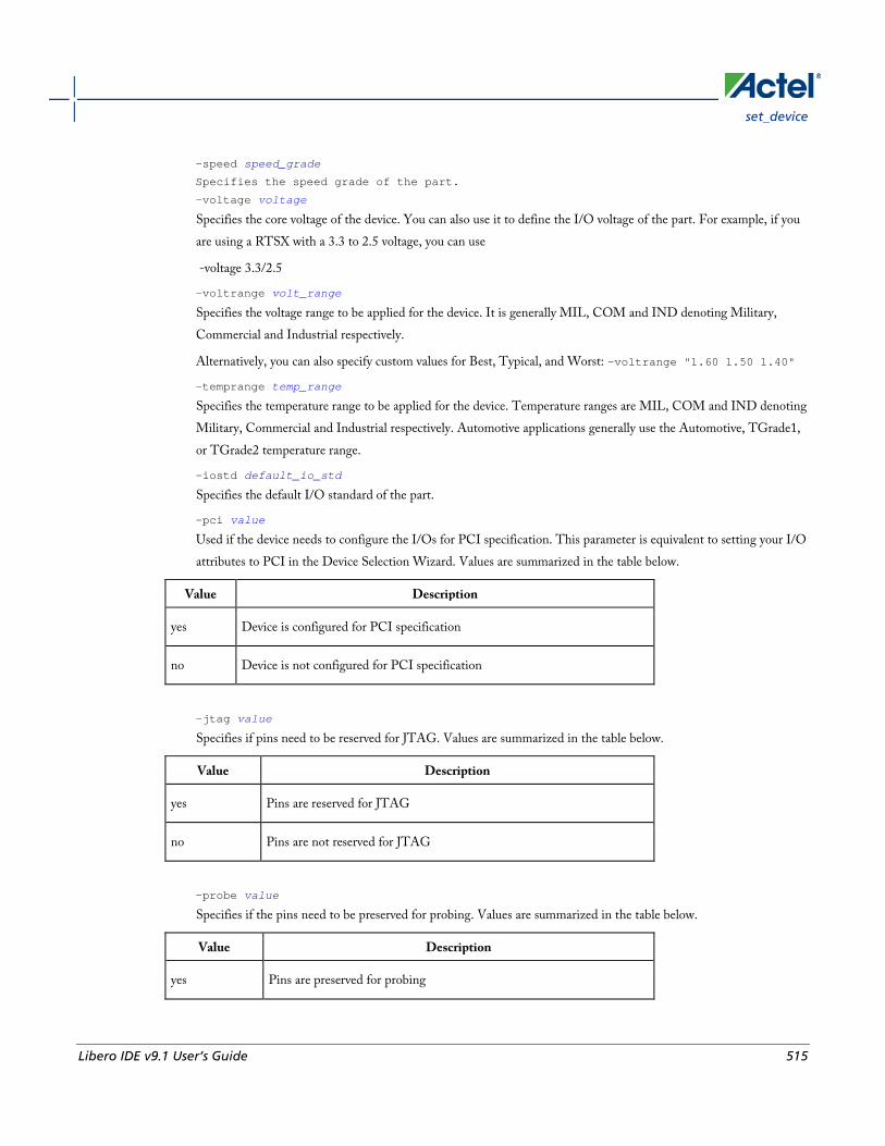
set_device
Libero IDE v9.1 User’s Guide 515
-speed speed_grade
Specifies the speed grade of the part.
-voltage voltage
Specifies the core voltage of the device. You can also use it to define the I/O voltage of the part. For example, if you are using a RTSX with a 3.3 to 2.5 voltage, you can use
-voltage 3.3/2.5
-voltrange volt_range
Specifies the voltage range to be applied for the device. It is generally MIL, COM and IND denoting Military, Commercial and Industrial respectively.
Alternatively, you can also specify custom values for Best, Typical, and Worst: -voltrange "1.60 1.50 1.40"
-temprange temp_range
Specifies the temperature range to be applied for the device. Temperature ranges are MIL, COM and IND denoting Military, Commercial and Industrial respectively. Automotive applications generally use the Automotive, TGrade1, or TGrade2 temperature range.
-iostd default_io_std
Specifies the default I/O standard of the part.
-pci value
Used if the device needs to configure the I/Os for PCI specification. This parameter is equivalent to setting your I/O attributes to PCI in the Device Selection Wizard. Values are summarized in the table below.
Value Description
yes Device is configured for PCI specification
no Device is not configured for PCI specification
-jtag value
Specifies if pins need to be reserved for JTAG. Values are summarized in the table below.
Value Description
yes Pins are reserved for JTAG
no Pins are not reserved for JTAG
-probe value
Specifies if the pins need to be preserved for probing. Values are summarized in the table below.
Value Description
yes Pins are preserved for probing
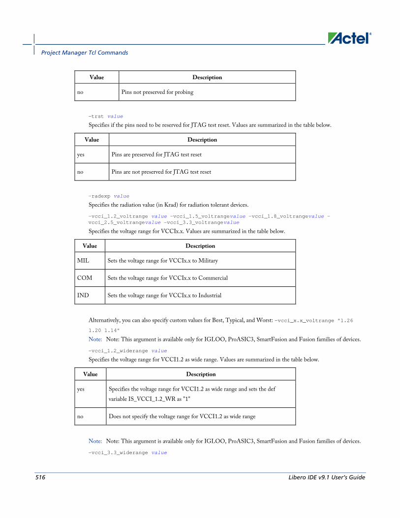
Project Manager Tcl Commands
516 Libero IDE v9.1 User’s Guide
Value Description
no Pins not preserved for probing
-trst value
Specifies if the pins need to be reserved for JTAG test reset. Values are summarized in the table below.
Value Description
yes Pins are preserved for JTAG test reset
no Pins are not preserved for JTAG test reset
-radexp value
Specifies the radiation value (in Krad) for radiation tolerant devices.
-vcci_1.2_voltrange value -vcci_1.5_voltrangevalue -vcci_1.8_voltrangevalue -vcci_2.5_voltrangevalue -vcci_3.3_voltrangevalue
Specifies the voltage range for VCCIx.x. Values are summarized in the table below.
Value Description
MIL Sets the voltage range for VCCIx.x to Military
COM Sets the voltage range for VCCIx.x to Commercial
IND Sets the voltage range for VCCIx.x to Industrial
Alternatively, you can also specify custom values for Best, Typical, and Worst: -vcci_x.x_voltrange "1.26 1.20 1.14" Note: Note: This argument is available only for IGLOO, ProASIC3, SmartFusion and Fusion families of devices.
-vcci_1.2_widerange value
Specifies the voltage range for VCCI1.2 as wide range. Values are summarized in the table below.
Value Description
yes Specifies the voltage range for VCCI1.2 as wide range and sets the def variable IS_VCCI_1.2_WR as "1"
no Does not specify the voltage range for VCCI1.2 as wide range
Note: Note: This argument is available only for IGLOO, ProASIC3, SmartFusion and Fusion families of devices.
-vcci_3.3_widerange value
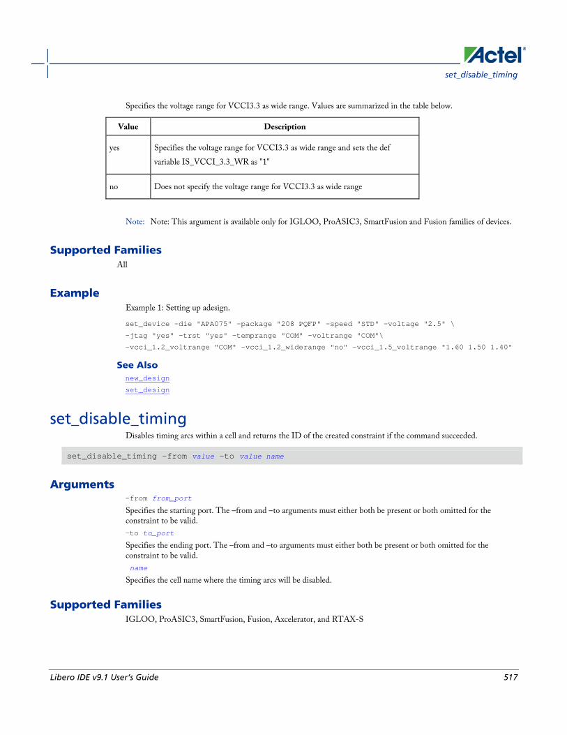
set_disable_timing
Libero IDE v9.1 User’s Guide 517
Specifies the voltage range for VCCI3.3 as wide range. Values are summarized in the table below.
Value Description
yes Specifies the voltage range for VCCI3.3 as wide range and sets the def variable IS_VCCI_3.3_WR as "1"
no Does not specify the voltage range for VCCI3.3 as wide range
Note: Note: This argument is available only for IGLOO, ProASIC3, SmartFusion and Fusion families of devices.
Supported Families All
Example Example 1: Setting up adesign.
set_device -die "APA075" -package "208 PQFP" -speed "STD" -voltage "2.5" \
-jtag "yes" -trst "yes" -temprange "COM" -voltrange "COM"\
-vcci_1.2_voltrange "COM" -vcci_1.2_widerange "no" -vcci_1.5_voltrange "1.60 1.50 1.40"
See Also new_design
set_design
set_disable_timing Disables timing arcs within a cell and returns the ID of the created constraint if the command succeeded.
set_disable_timing -from value -to value name
Arguments -from from_port
Specifies the starting port. The –from and –to arguments must either both be present or both omitted for the constraint to be valid. -to to_port
Specifies the ending port. The –from and –to arguments must either both be present or both omitted for the constraint to be valid. name
Specifies the cell name where the timing arcs will be disabled.
Supported Families IGLOO, ProASIC3, SmartFusion, Fusion, Axcelerator, and RTAX-S

Project Manager Tcl Commands
518 Libero IDE v9.1 User’s Guide
Exceptions • None
Example set_disable_timing -from A -to Y a2
set_false_path Identifies paths that are considered false and excluded from the timing analysis in the current timing scenario.
set_false_path [-from from_list] [-through through_list] [-to to_list]
Arguments -from from_list
Specifies a list of timing path starting points. A valid timing starting point is a clock, a primary input, an inout port, or a clock pin of a sequential cell. -through through_list
Specifies a list of pins, ports, cells, or nets through which the disabled paths must pass. -to to_list
Specifies a list of timing path ending points. A valid timing ending point is a clock, a primary output, an inout port, or a data pin of a sequential cell.
Supported Families IGLOO, ProASIC3, SmartFusion, Fusion, ProASICPLUS, ProASIC (for analysis), Axcelerator, RTAX-S, eX (-through option), and SX-A (-through option)
Description The set_false_path command identifies specific timing paths as being false. The false timing paths are paths that do not propagate logic level changes. This constraint removes timing requirements on these false paths so that they are not considered during the timing analysis. The path starting points are the input ports or register clock pins, and the path ending points are the register data pins or output ports. This constraint disables setup and hold checking for the specified paths.
The false path information always takes precedence over multiple cycle path information and overrides maximum delay constraints. If more than one object is specified within one -through option, the path can pass through any objects.
You must specify at least one of the –from, -to, or –through arguments for this constraint to be valid.
Examples The following example specifies all paths from clock pins of the registers in clock domain clk1 to data pins of a specific register in clock domain clk2 as false paths:
set_false_path –from [get_clocks {clk1}] –to reg_2:D

set_input_delay
Libero IDE v9.1 User’s Guide 519
The following example specifies all paths through the pin U0/U1:Y to be false:
set_false_path -through U0/U1:Y
See Also Tcl Command Documentation Conventions
set_input_delay Creates an input delay on a port list by defining the arrival time of an input relative to a clock in the current scenario.
set_input_delay delay_value -clock clock_ref [–max] [–min] [–clock_fall] input_list
Arguments delay_value
Specifies the arrival time in nanoseconds that represents the amount of time for which the signal is available at the specified input after a clock edge. -clock clock_ref
Specifies the clock reference to which the specified input delay is related. This is a mandatory argument. If you do not specify -max or -min options, the tool assumes the maximum and minimum input delays to be equal. -max
Specifies that delay_value refers to the longest path arriving at the specified input. If you do not specify -max or -min options, the tool assumes maximum and minimum input delays to be equal. -min
Specifies that delay_value refers to the shortest path arriving at the specified input. If you do not specify -max or -min options, the tool assumes maximum and minimum input delays to be equal. -clock_fall
Specifies that the delay is relative to the falling edge of the clock reference. The default is the rising edge. input_list
Provides a list of input ports in the current design to which delay_value is assigned. If you need to specify more than one object, enclose the objects in braces ({}).
Supported Families IGLOO, ProASIC3, SmartFusion, Fusion, ProASICPLUS, ProASIC (for analysis), Axcelerator, RTAX-S, eX (for analysis), SX-A (for analysis)
Description The set_input_delay command sets input path delays on input ports relative to a clock edge. This usually represents a combinational path delay from the clock pin of a register external to the current design. For in/out (bidirectional) ports, you can specify the path delays for both input and output modes. The tool adds input delay to path delay for paths starting at primary inputs.
A clock is a singleton that represents the name of a defined clock constraint. This can be:
• a single port name used as source for a clock constraint

Project Manager Tcl Commands
520 Libero IDE v9.1 User’s Guide
• a single pin name used as source for a clock constraint; for instance reg1:CLK. This name can be hierarchical (for instance toplevel/block1/reg2:CLK)
• an object accessor that will refer to one clock: [get_clocks {clk}]
Examples The following example sets an input delay of 1.2ns for port data1 relative to the rising edge of CLK1:
set_input_delay 1.2 -clock [get_clocks CLK1] [get_ports data1]
The following example sets a different maximum and minimum input delay for port IN1 relative to the falling edge of CLK2:
set_input_delay 1.0 -clock_fall -clock CLK2 –min {IN1}
set_input_delay 1.4 -clock_fall -clock CLK2 –max {IN1}
See Also set_output_delay
Tcl Command Documentation Conventions
set_max_delay Specifies the maximum delay for the timing paths in the current scenario.
set_max_delay delay_value [-from from_list] [-to to_list] [-through through_list]
Arguments delay_value
Specifies a floating point number in nanoseconds that represents the required maximum delay value for specified paths.
• If the path starting point is on a sequential device, the tool includes clock skew in the computed delay.
• If the path starting point has an input delay specified, the tool adds that delay value to the path delay.
• If the path ending point is on a sequential device, the tool includes clock skew and library setup time in the computed delay.
• If the ending point has an output delay specified, the tool adds that delay to the path delay.
-from from_list
Specifies a list of timing path starting points. A valid timing starting point is a clock, a primary input, an inout port, or a clock pin of a sequential cell. -to to_list
Specifies a list of timing path ending points. A valid timing ending point is a clock, a primary output, an inout port, or a data pin of a sequential cell. -through through_list

set_min_delay
Libero IDE v9.1 User’s Guide 521
Specifies a list of pins, ports, cells, or nets through which the timing paths must pass.
Supported Families IGLOO, ProASIC3, SmartFusion, Fusion, ProASICPLUS, ProASIC (for analysis), Axcelerator, RTAX-S, eX (-through option), and SX-A (-through option)
Description This command specifies the required maximum delay for timing paths in the current design. The path length for any startpoint in from_list to any endpoint in to_list must be less than delay_value.
The timing engine automatically derives the individual maximum delay targets from clock waveforms and port input or output delays.
The maximum delay constraint is a timing exception. This constraint overrides the default single cycle timing relationship for one or more timing paths. This constraint also overrides a multicycle path constraint.
You must specify at least one of the –from, -to, or –through arguments for this constraint to be valid.
Examples The following example sets a maximum delay by constraining all paths from ff1a:CLK or ff1b:CLK to ff2e:D with a delay less than 5 ns:
set_max_delay 5 -from {ff1a:CLK ff1b:CLK} -to {ff2e:D}
The following example sets a maximum delay by constraining all paths to output ports whose names start by “out” with a delay less than 3.8 ns:
set_max_delay 3.8 -to [get_ports out*]
See Also set_min_delay
remove_max_delay
Tcl Command Documentation Conventions
set_min_delay Specifies the minimum delay for the timing paths in the current scenario.
set_min_delay delay_value [-from from_list] [-to to_list] [-through through_list]
Arguments delay_value
Specifies a floating point number in nanoseconds that represents the required minimum delay value for specified paths.
• If the path starting point is on a sequential device, the tool includes clock skew in the computed delay.
Project Manager Tcl Commands
522 Libero IDE v9.1 User’s Guide
• If the path starting point has an input delay specified, the tool adds that delay value to the path delay.
• If the path ending point is on a sequential device, the tool includes clock skew and library setup time in the computed delay.
• If the ending point has an output delay specified, the tool adds that delay to the path delay.
-from from_list
Specifies a list of timing path starting points. A valid timing starting point is a clock, a primary input, an inout port, or a clock pin of a sequential cell. -to to_list
Specifies a list of timing path ending points. A valid timing ending point is a clock, a primary output, an inout port, or a data pin of a sequential cell. -through through_list Specifies a list of pins, ports, cells, or nets through which the timing paths must pass.
Supported Families IGLOO, ProASIC3, SmartFusion, Fusion, ProASICPLUS, ProASIC (for analysis), Axcelerator, RTAX-S, eX (-through option), and SX-A (-through option)
Description This command specifies the required minimum delay for timing paths in the current design. The path length for any startpoint in from_list to any endpoint in to_list must be less than delay_value.
The timing engine automatically derives the individual minimum delay targets from clock waveforms and port input or output delays.
The minimum delay constraint is a timing exception. This constraint overrides the default single cycle timing relationship for one or more timing paths. This constraint also overrides a multicycle path constraint.
You must specify at least one of the –from, -to, or –through arguments for this constraint to be valid.
Examples The following example sets a minimum delay by constraining all paths from ff1a:CLK or ff1b:CLK to ff2e:D with a delay less than 5 ns:
set_min_delay 5 -from {ff1a:CLK ff1b:CLK} -to {ff2e:D}
The following example sets a minimum delay by constraining all paths to output ports whose names start by “out” with a delay less than 3.8 ns:
set_min_delay 3.8 -to [get_ports out*]
See Also set_max_delay
remove_min_delay

set_multicycle_path
Libero IDE v9.1 User’s Guide 523
Tcl Command Documentation Conventions
set_multicycle_path Defines a path that takes multiple clock cycles in the current scenario.
set_multicycle_path ncycles [-setup] [-hold] [-from from_list[–through through_list[-to to_list
Arguments ncycles
Specifies an integer value that represents a number of cycles the data path must have for setup or hold check. The value is relative to the starting point or ending point clock, before data is required at the ending point. -setup
Optional. Applies the cycle value for the setup check only. This option does not affect the hold check. The default hold check will be applied unless you have specified another set_multicycle_path command for the hold value. -hold
Optional. Applies the cycle value for the hold check only. This option does not affect the setup check. Note: Note: If you do not specify "-setup" or "-hold", the cycle value is applied to the setup check and the default
hold check is performed (ncycles -1).
-from from_list
Specifies a list of timing path starting points. A valid timing starting point is a clock, a primary input, an inout port, or a clock pin of a sequential cell. -through through_list
Specifies a list of pins or ports through which the multiple cycle paths must pass. -to to_list
Specifies a list of timing path ending points. A valid timing ending point is a clock, a primary output, an inout port, or a data pin of a sequential cell.
Supported Families IGLOO, ProASIC3, SmartFusion, Fusion, ProASICPLUS, ProASIC (for analysis), Axcelerator, RTAX-S, eX (for analysis), SX-A (for analysis)
Description Setting multiple cycle paths constraint overrides the single cycle timing relationships between sequential elements by specifying the number of cycles that the data path must have for setup or hold checks. If you change the multiplier, it affects both the setup and hold checks.
False path information always takes precedence over multiple cycle path information. A specific maximum delay constraint overrides a general multiple cycle path constraint.
If you specify more than one object within one -through option, the path passes through any of the objects.
You must specify at least one of the –from, -to, or –through arguments for this constraint to be valid.

Project Manager Tcl Commands
524 Libero IDE v9.1 User’s Guide
Exceptions • Multiple priority management is not supported in Actel designs. All multiple cycle path constraints are handled
with the same priority.
Examples The following example sets all paths between reg1 and reg2 to 3 cycles for setup check. Hold check is measured at the previous edge of the clock at reg2.
set_multicycle_path 3 -from [get_pins {reg1}] –to [get_pins {reg2}]
The following example specifies that four cycles are needed for setup check on all paths starting at the registers in the clock domain ck1. Hold check is further specified with two cycles instead of the three cycles that would have been applied otherwise.
set_multicycle_path 4 -setup -from [get_clocks {ck1}]
set_multicycle_path 2 -hold -from [get_clocks {ck1}]
See Also remove_multicycle_path
Tcl Command Documentation Conventions
set_output_delay Defines the output delay of an output relative to a clock in the current scenario.
set_output_delay delay_value -clock clock_ref [–max] [–min] [–clock_fall] output_list
Arguments delay_value
Specifies the amount of time before a clock edge for which the signal is required. This represents a combinational path delay to a register outside the current design plus the library setup time (for maximum output delay) or hold time (for minimum output delay). -clock clock_ref
Specifies the clock reference to which the specified output delay is related. This is a mandatory argument. If you do not specify -max or -min options, the tool assumes the maximum and minimum input delays to be equal. -max
Specifies that delay_value refers to the longest path from the specified output. If you do not specify -max or -min options, the tool assumes the maximum and minimum output delays to be equal. -min
Specifies that delay_value refers to the shortest path from the specified output. If you do not specify -max or -min options, the tool assumes the maximum and minimum output delays to be equal. -clock_fall
Specifies that the delay is relative to the falling edge of the clock reference. The default is the rising edge. output_list
Provides a list of output ports in the current design to which delay_value is assigned. If you need to specify more than one object, enclose the objects in braces ({}).

smartpower_add_new_custom_mode
Libero IDE v9.1 User’s Guide 525
Supported Families IGLOO, ProASIC3, SmartFusion, Fusion, ProASICPLUS, ProASIC (for analysis), Axcelerator, RTAX-S, eX (for analysis), SX-A (for analysis)
Description The set_output_delay command sets output path delays on output ports relative to a clock edge. Output ports have no output delay unless you specify it. For in/out (bidirectional) ports, you can specify the path delays for both input and output modes. The tool adds output delay to path delay for paths ending at primary outputs.
Examples The following example sets an output delay of 1.2ns for port OUT1 relative to the rising edge of CLK1:
set_output_delay 1.2 -clock [get_clocks CLK1] [get_ports OUT1]
The following example sets a different maximum and minimum output delay for port OUT1 relative to the falling edge of CLK2:
set_output_delay 1.0 -clock_fall -clock CLK2 –min {OUT1}
set_output_delay 1.4 -clock_fall -clock CLK2 –max {OUT1}
See Also remove_output_delay
set_input_delay
Tcl Command Documentation Conventions
smartpower_add_new_custom_mode Creates a new custom mode.
smartpower_add_new_custom_mode -name {mode_name} -base_mode {base_mode} -description {mode_description}
Arguments -name {mode_name}
Specifies the name of the new custom mode. -base_mode {base_mode}
Specifies the name of the base mode used to create the new custom mode. -description {mode_description}
Specifies the description of the new custom mode.
Supported Families IGLOO, ProASIC3, SmartFusion, Fusion, ProASICPLUS, ProASIC, and Axcelerator
Notes • None

Project Manager Tcl Commands
526 Libero IDE v9.1 User’s Guide
Exceptions • None
Examples This example creates a new custom mode "Cust_1" based on the Active mode:
smartpower_add_new_custom_mode -name {Cust_1} -base_mode {Active} -description {frequency 10 MHz}
See Also smartpower_remove_custom_mode
smartpower_add_new_scenario Creates a new scenario.
smartpower_add_new_scenario -name {value} -description {value} -mode {value}
Arguments -name {value}
Specifies the name of the new scenario. -description {value}
Specifies the description of the new scenario. -mode {<operating mode>:<duration>}+
Specifies the mode(s) and duration(s) for the specified scenario.
Supported Families IGLOO, ProASIC3, SmartFusion, Fusion, ProASICPLUS, ProASIC, and Axcelerator
Notes • None
Exceptions • None
Examples This example creates a new scenario called myscenario:
smartpower_add_new_scenario -name myscenario -description mynewscenario -mode active:30 + shutdown:30 + active:40
smartpower_add_pin_in_domain Adds a pin into a clock or set domain.

smartpower_add_pin_in_domain
Libero IDE v9.1 User’s Guide 527
smartpower_add_pin_in_domain -pin_name {pin_name} -pin_type {value} –domain_name {domain_name} -domain_type {value}
Arguments -pin_name {pin_name}
Specifies the name of the pin to add to the domain. -pin_type {value}
Specifies the type of the pin to add. The following table shows the acceptable values for this argument:
Value Description
clock The pin to add is a clock pin
data The pin to add is a data pin
-domain_name {domain_name}
Specifies the name of the domain in which to add the specified pin. -domain_type {value}
Specifies the type of domain in which to add the specified pin. The following table shows the acceptable values for this argument:
Value Description
clock The domain is a clock domain
set The domain is a set domain
Supported Families IGLOO, ProASIC3, SmartFusion, Fusion, ProASICPLUS, ProASIC, and Axcelerator
Notes • The domain_name must be a name of an existing domain.
• The pin_name must be a name of a pin that exists in the design.
Exceptions • None
Examples The following example adds a clock pin to an existing Clock domain:
smartpower_add_pin_in_domain -pin_name { XCMP3/U0/U1:Y } -pin_type {clock} –domain_name {clk1} -domain_type {clock}

Project Manager Tcl Commands
528 Libero IDE v9.1 User’s Guide
The following example adds a data pin to an existing Set domain:
smartpower_add_pin_in_domain -pin_name {XCMP3/U0/U1:Y} -pin_type {data} -domain_name {myset} -domain_type {set}
See Also smartpower_remove_pin_of_domain
smartpower_change_clock_statistics Changes the default frequencies and probabilities for a specific domain.
smartpower_change_clock_statistics -domain_name {value} -clocks_freq {value} -clocks_proba {value} -registers_freq {value} -registers_proba {value} -set_reset_freq {value} -set_reset_proba {value} -primaryinputs_freq {value} -primaryinputs_proba {value} -combinational_freq {value} -combinational_proba {value}
Arguments -domain_name{value}
Specifies the domain name in which to initialize frequencies and probabilities. -clocks_freq {value}
Specifies the user input frequency in Hz, KHz, or MHz for all clocks. -clocks_proba {value}
Specifies the user input probability in % for all clocks. -registers_freq {value}
Specifies the user input frequency (in Hz, KHz, or MHz) or the toggle rate (in %). If the unit is not provided and toggle rate is active, the value is handled as a toggle rate; if toggle rate is not active, the value is handled as a frequency. -registers_proba {value}
Specifies the user input probability in % for all registers. -set_reset_freq {value}
Specifies the user input frequency (in Hz, KHz, or MHz) or the toggle rate (in %). If the unit is not provided and toggle rate is active, the value is handled as a toggle rate; if toggle rate is not active, the value is handled as a frequency. -set_reset_proba {value}
Specifies the user input probability in % for all set/reset nets. -primaryinputs_freq {value}
Specifies the user input frequency (in Hz, KHz, or MHz) or the toggle rate (in %). If the unit is not provided and toggle rate is active, the value is handled as a toggle rate; if toggle rate is not active, the value is handled as a frequency. -primaryinputs_proba {value}
Specifies the user input probability in % for all primary inputs. -combinational_freq {value}
Specifies the user input frequency (in Hz, KHz, or MHz) or the toggle rate (in %). If the unit is not provided and toggle rate is active, the value is handled as a toggle rate; if toggle rate is not active, the value is handled as a frequency. -combinational_proba {value}
Specifies the user input probability in % for all combinational combinational output.

smartpower_change_setofpin_statistics
Libero IDE v9.1 User’s Guide 529
Supported Families IGLOO, ProASIC3, SmartFusion, Fusion, ProASICPLUS, ProASIC, and Axcelerator
Notes • This command is associated with the functionality of Initialize frequencies and probabilities dialog box.
Exceptions • None
Examples The following example initializes all clocks withs:
smartpower_change_clock_statistics -domain_name {my_domain} -clocks_freq {10 MHz} -clocks_proba {20} -registers_freq {10 MHz} -registers_proba {20} -set_reset_freq {10 MHz} -set_reset_proba {20} -primaryinputs_freq {10 MHz} -primaryinputs_proba {20} -combinational_freq {10 MHz} -combinational_proba {20}
smartpower_change_setofpin_statistics Changes the default frequencies and probabilities for a specific set.
smartpower_change_setofpin_statistics -domain_name {value} -data_freq {value} -data_proba {value}
Arguments -domain_name{value}
Specifies the domain name in which to initialize data frequencies and probabilities. -data_freq {value}
Specifies the user input data frequency in Hz, KHz, or MHz for all sets of pins. -data_proba {value}
Specifies the user input data probability in % for all sets of pins.
Supported Families IGLOO, ProASIC3, SmartFusion, Fusion, ProASICPLUS, ProASIC, and Axcelerator
Notes • This command is associated with the functionality of Initialize frequencies and probabilities dialog box.
Exceptions • None
Project Manager Tcl Commands
530 Libero IDE v9.1 User’s Guide
Examples The following example initializes all clocks withs:
smartpower_change_setofpin_statistics -domain_name {my_domain} -data_freq {10 MHz} -data_proba {20}
smartpower_commit Saves the changes to the design (.adb) file.
smartpower_commit
Arguments • None
Supported Families IGLOO, ProASIC3, SmartFusion, Fusion, ProASICPLUS, ProASIC, and Axcelerator
Notes • None
Exceptions • None
Examples smartpower_commit
See Also smartpower_restore
smartpower_create_domain Creates a new clock or set domain.
smartpower_create_domain -domain_type {value} -domain_name {domain_name}
Arguments -domain_type {value}
Specifies the type of domain to create. The following table shows the acceptable values for this argument:
Value Description
clock The domain is a clock domain

smartpower_edit_custom_mode
Libero IDE v9.1 User’s Guide 531
Value Description
set The domain is a set domain
-domain_name {domain_name}
Specifies the name of the new domain.
Supported Families IGLOO, ProASIC3, SmartFusion, Fusion, ProASICPLUS, ProASIC, and Axcelerator
Notes • The domain name cannot be the name of an existing domain.
• The domain type must be either clock or set.
Exceptions • None
Examples The following example creates a new clock domain named "clk2":
smartpower_create_domain -domain_type {clock} -domain_name {clk2}
The following example creates a new set domain named "myset":
smartpower_create_domain -domain_type {set} -domain_name {myset}
See Also smartpower_remove_domain
smartpower_edit_custom_mode Edits a custom mode.
smartpower_edit_custom_mode -name {old_mode_name} new_name {new_mode_name} -description {mode_description}
Arguments -name {old_mode_name}
Specifies the name of the custom mode you want to edit. -new_name {new_mode_name}
Specifies the new name of the custom mode. -description {mode_description}
Specifies the description of the new custom mode.

Project Manager Tcl Commands
532 Libero IDE v9.1 User’s Guide
Supported Families IGLOO, ProASIC3, SmartFusion, Fusion, ProASICPLUS, ProASIC, and Axcelerator
Notes • None
Exceptions • None
Examples This example edits custom mode "Cust_1" and renames it "Cust_2":
smartpower_edit_custom_mode -name {Cust_1} -new_name {Cust_2} -description {frequency 10 MHz}
See Also smartpower_remove_custom_mode
smartpower_add_custom_mode
smartpower_edit_scenario Edits a scenario.
smartpower_edit_scenario -name {value} -description {value} -mode {value} -new_name {value}
Arguments -name {value}
Specifies the name of the scenario. -description {value}
Specifies the description of the scenario. -mode {<operating mode>:<duration>}
Specifies the mode(s) and duration(s) for the specified scenario. -new_name {value}
Specifies the new name for the scenario
Supported Families IGLOO, ProASIC3, SmartFusion, Fusion, ProASICPLUS, ProASIC, and Axcelerator
Notes • None
Exceptions • None
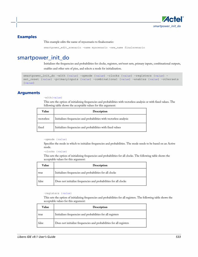
smartpower_init_do
Libero IDE v9.1 User’s Guide 533
Examples This example edits the name of myscenario to finalscenario:
smartpower_edit_scenario -name myscenario -new_name finalscenario
smartpower_init_do Initializes the frequencies and probabilities for clocks, registers, set/reset nets, primary inputs, combinational outputs, enables and other sets of pins, and selects a mode for initialization.
smartpower_init_do -with {value} -opmode {value} -clocks {value} -registers {value} -set_reset {value} -primaryinputs {value} -combinational {value} -enables {value} -othersets {value}
Arguments -with{value}
This sets the option of initializing frequencies and probabilities with vectorless analysis or with fixed values. The following table shows the acceptable values for this argument:
Value Description
vectorless Initializes frequencies and probabilities with vectorless analysis
fixed Initializes frequencies and probabilities with fixed values
-opmode {value}
Specifies the mode in which to initialize frequencies and probabilities. The mode needs to be based on an Active mode. -clocks {value}
This sets the option of initializing frequencies and probabilities for all clocks. The following table shows the acceptable values for this argument:
Value Description
true Initializes frequencies and probabilities for all clocks
false Does not initialize frequencies and probabilities for all clocks
-registers {value}
This sets the option of initializing frequencies and probabilities for all registers. The following table shows the acceptable values for this argument:
Value Description
true Initializes frequencies and probabilities for all registers
false Does not initialize frequencies and probabilities for all registers
Project Manager Tcl Commands
534 Libero IDE v9.1 User’s Guide
-set_reset {value}
This sets the option of initializing frequencies and probabilities for all set/reset nets. The following table shows the acceptable values for this argument:
Value Description
true Initializes frequencies and probabilities for all set/reset nets
false Does not initialize frequencies and probabilities for all set/reset nets
-primaryinputs{value}
This sets the option of initializing frequencies and probabilities for all primary inputs. The following table shows the acceptable values for this argument:
Value Description
true Initializes frequencies and probabilities for all primary inputs
false Does not initialize frequencies and probabilities for all primary inputs
-combinational {value}
This sets the option of initializing frequencies and probabilities for all combinational outputs. The following table shows the acceptable values for this argument:
Value Description
true Initializes frequencies and probabilities for all combinational outputs
false Does not initialize frequencies and probabilities for all combinational outputs
-enables {value}
This sets the option of initializing frequencies and probabilities for all enable sets of pins. The following table shows the acceptable values for this argument:
Value Description
true Initializes frequencies and probabilities for all enable sets of pins
false Does not initialize frequencies and probabilities for all enable sets of pins
-othersets {value}
This sets the option of initializing frequencies and probabilities for all other sets of pins. The following table shows the acceptable values for this argument:

smartpower_init_set_clocks_options
Libero IDE v9.1 User’s Guide 535
Value Description
true Initializes frequencies and probabilities for all other sets of pins
false Does not initialize frequencies and probabilities for all other sets of pins
Supported Families IGLOO, ProASIC3, SmartFusion, Fusion, ProASICPLUS, ProASIC, and Axcelerator
Note: Vectorless estimation is not supported for ProASIC, ProasicPLUS, and Axcelerator devices.
Notes • This command is associated with the functionality of Initialize frequencies and probabilities dialog box.
Exceptions • None
Examples The following example initializes all clocks with:
smartpower_init_do -with {vectorless} -opmode {my_mode} -clocks {true} -registers {true} -asynchronous {true} -primaryinputs {true} -combinational {true} -enables {true} -othersets {true}
smartpower_init_set_clocks_options Initializes the clock frequency options of all clock domains.
smartpower_init_set_clocks_options -with_clock_constraints {value} -with_default_values {value} -freq {value} -duty_cycle {value}
Arguments -with_clock_constraints {value}
This sets the option of initializing the clock frequencies with frequency constraints from SmartTime. The following table shows the acceptable values for this argument:
Value Description
true Sets initialize clock frequencies with clock constraints ON
false Sets initialize clock frequencies with clock constraints OFF
-with_default_values {value}

Project Manager Tcl Commands
536 Libero IDE v9.1 User’s Guide
This sets the option of initializing the clock frequencies with a user input default value. The following table shows the acceptable values for this argument:
Value Description
true Sets initialize clock frequencies with default values ON
false Sets initialize clock frequencies with default values OFF
-freq {value}
Specifies the user input frequency in Hz, KHz, or MHz. -duty_cycle {value}
Specifies the user input duty cycles in %.
Supported Families IGLOO, ProASIC3, SmartFusion, Fusion, ProASICPLUS, ProASIC, and Axcelerator
Notes • This command is associated with the functionality of Initialize frequencies and probabilities dialog box.
Exceptions • None
Examples The following example initializes all clocks after executing smartpower_init_do with -clocks {true}:
smartpower_init_set_clocks_options -with_clock_constraints {true} -with_default_values {true} -freq {10 MHz} -duty_cycle {20}
smartpower_init_set_combinational_options Initializes the frequency and probability of all combinational outputs.
smartpower_init_set_combinational_options -freq {value} -proba {value}
Arguments -freq {value}
Specifies the user input frequency (in Hz, KHz, or MHz) or the toggle rate (in %). If the unit is not provided and toggle rate is active, the value is handled as a toggle rate; if toggle rate is not active, the value is handled as a frequency. -proba {value}
Specifies the user input probability in %.

smartpower_init_setofpins_values
Libero IDE v9.1 User’s Guide 537
Supported Families IGLOO, ProASIC3, SmartFusion, Fusion, ProASICPLUS, ProASIC, and Axcelerator
Notes • This command is associated with the functionality of Initialize frequencies and probabilities dialog box.
Exceptions • None
Examples The following example initializes all combinational signals after executing smartpower_init_do with -combinational {true}:
smartpower_init_set_combinational_options -freq {10 MHz} -proba {20}
smartpower_init_setofpins_values Initializes the frequency and probability of all sets of pins.
smartpower_init_setofpins_values -domain_name {name} -freq {value} -proba {value}
Arguments -domain_name{name}
Specifies the set of pins that will be initialized. The following table shows the acceptable values for this argument:
Value Description
IOsEnableSet Specifies that the IOsEnableSet set of pins will be initialized
MemoriesEnableSet Specifies that the MemoriesEnableSet set of pins will be initialized
-freq {value}
Specifies the user input frequency in Hz, MHz, or KHz. -proba {value}
Specifies the user input probability in %.
Supported Families IGLOO, ProASIC3, SmartFusion, Fusion, ProASICPLUS, ProASIC, and Axcelerator
Notes • This command is associated with the functionality of Initialize frequencies and probabilities dialog box.

Project Manager Tcl Commands
538 Libero IDE v9.1 User’s Guide
Exceptions • None
Examples The following example initializes all primary inputs after executing smartpower_init_do with -othersets {true}:
smartpower_init_setofpins_values -domain_name {IOsEnableSet} -freq {10 MHz} -proba {20}
smartpower_init_set_enables_options Initializes the clock frequency of all enable clocks with the initialization options.
smartpower_init_set_enables_options -freq {value} -proba {value}
Arguments -freq {value}
Specifies the user input frequency (in Hz, KHz, or MHz). -proba {value}
Specifies the user input probability in %.
Supported Families IGLOO, ProASIC3, SmartFusion, Fusion, ProASICPLUS, ProASIC, and Axcelerator
Notes • This command is associated with the functionality of Initialize frequencies and probabilities dialog box.
Exceptions • None
Examples The following example initializes all clocks after executing smartpower_init_do with -enables {true}:
smartpower_init_set_enables_options -freq {10 MHz} -proba {20}
smartpower_init_set_othersets_options Initializes the frequency and probability of all other sets.
smartpower_init_set_othersets_options [-freq "decimal value [ unit { Hz | KHz | MHz } ]"] [-proba "decimal value"] [-with "vectorless | default"] [-input_freq "decimal value [ unit { Hz | KHz | MHz } ]"] [-input_proba "decimal value"]
smartpower_init_set_primaryinputs_options
Libero IDE v9.1 User’s Guide 539
Arguments -freq "decimal value [unit {Hz | KHz| MHz}"
Specifies the default frequency and units. -proba {decimal value}
Specifies the default probability. -with "vectorless | default"
Specifies vectorless or default analysis. -input_freq "decimal value [unit {Hz | KHz| MHz}"
Specifies the input frequency and units. -input_proba {decimal value}
Specifies the input probability.
Supported Families IGLOO, ProASIC3, SmartFusion, Fusion, ProASICPLUS, ProASIC, and Axcelerator
Notes • This command is associated with the functionality of Initialize Frequencies and Probabilities dialog box.
Exceptions • None
Examples The following example initializes all other sets after executing smartpower_init_do with -othersets {true}:
smartpower_init_set_othersets_options -freq {10 MHz} -proba {20} [-with default]
smartpower_init_set_primaryinputs_options Initializes the frequency and probability of all primary inputs.
smartpower_init_set_primaryinputs_options -freq {value} -proba {value}
Arguments -freq {value}
Specifies the user input frequency (in Hz, KHz, or MHz) or the toggle rate (in %). If the unit is not provided and toggle rate is active, the value is handled as a toggle rate; if toggle rate is not active, the value is handled as a frequency. -proba {value}
Specifies the user input probability in %.
Supported Families IGLOO, ProASIC3, SmartFusion, Fusion, ProASICPLUS, ProASIC, and Axcelerator

Project Manager Tcl Commands
540 Libero IDE v9.1 User’s Guide
Notes • This command is associated with the functionality of Initialize frequencies and probabilities dialog box.
Exceptions • None
Examples The following example initializes all primary inputs after executing smartpower_init_do with -primaryinputs {true}:
smartpower_init_set_primaryinputs_options -freq {10 MHz} -proba {20}
smartpower_init_set_registers_options Initializes the frequency and probability of all register outputs.
smartpower_init_set_registers_options -freq {value} -proba {value}
Arguments -freq {value}
Specifies the user input frequency (in Hz, KHz, or MHz) or the toggle rate (in %). If the unit is not provided and toggle rate is active, the value is handled as a toggle rate; if toggle rate is not active, the value is handled as a frequency. -proba {value}
Specifies the user input probability in %.
Supported Families IGLOO, ProASIC3, SmartFusion, Fusion, ProASICPLUS, ProASIC, and Axcelerator
Notes • This command is associated with the functionality of Initialize frequencies and probabilities dialog box.
Exceptions • None
Examples The following example initializes all register outputs after executing smartpower_init_do with -registers {true}:
smartpower_init_set_registers_options -freq {10 MHz} -proba {20}

smartpower_init_set_set_reset_options
Libero IDE v9.1 User’s Guide 541
smartpower_init_set_set_reset_options Initializes the frequency and probability of all set and reset nets.
smartpower_init_set_set_reset_options -freq {value} -proba {value}
Arguments -freq {value}
Specifies the user input frequency (in Hz, KHz, or MHz) or the toggle rate (in %). If the unit is not provided and toggle rate is active, the value is handled as a toggle rate; if toggle rate is not active, the value is handled as a frequency. -proba {value}
Specifies the user input probability in %.
Supported Families IGLOO, ProASIC3, SmartFusion, Fusion, ProASICPLUS, ProASIC, and Axcelerator
Notes • This command is associated with the functionality of Initialize frequencies and probabilities dialog box.
Exceptions • None
Examples The following example initializes all set/reset nets after executing smartpower_init_do with -set_reset {true}:
smartpower_init_set_set_reset_options -freq {10 MHz} -proba {20}
smartpower_remove_all_annotations Removes all initialization annotations for the specified mode.
smartpower_remove_all_annotations -opmode {value}
Arguments -opmode {value}
Removes all initialization annotations for the specified mode.
Supported Families IGLOO, ProASIC3, SmartFusion, Fusion, ProASICPLUS, ProASIC, and Axcelerator

Project Manager Tcl Commands
542 Libero IDE v9.1 User’s Guide
Notes • This command is associated with the functionality of Initialize frequencies and probabilities dialog box.
Exceptions • None
Examples The following example initializes all clocks withs:
smartpower_remove_all_annotations -opmode {my_mode}
smartpower_remove_custom_mode Removes a custom mode.
smartpower_remove_custom_mode -name {deleted_mode_name}
Arguments -name {deleted_mode_name}
Specifies the name of the custom mode you want to delete.
Supported Families IGLOO, ProASIC3, SmartFusion, Fusion, ProASICPLUS, ProASIC, and Axcelerator
Notes • None
Exceptions • None
Examples This example delets custom mode "Cust_1":
smartpower_delete_custom_mode -name {Cust_1}
See Also sp_add_custom_mode
sp_edit_custom_mode
smartpower_remove_domain Removes an existing clock or set domain.
smartpower_remove_domain -domain_type {value} -domain_name {domain_name}

smartpower_remove_domain
Libero IDE v9.1 User’s Guide 543
Arguments -domain_type {value}
This specifies the type of domain to remove.The following table shows the acceptable values for this argument:
Value Description
clock The domain is a clock domain
set The domain is a set domain
-domain_name {domain_name}
This specifies the name of the domain to remove
Supported Families IGLOO, ProASIC3, SmartFusion, Fusion, ProASICPLUS, ProASIC, and Axcelerator
Notes The domain name must be the name of an existing domain. The domain type must be either clock or set.
Exceptions None
Examples The following example removes the clock domain named "clk2": smartpower_remove_domain -domain_type {clock} -domain_name {clk2}
The following example removes the set domain named "myset": smartpower_remove_domain -domain_type {set} -domain_name {myset}
See Also smartpower_create_domain
smartpower_remove_pin_enable_rate This command was obsoleted in SmartPower v8.5. Update your script to use smartpower_remove_pin_probability to remove the pin probability.
Note: Note: The information below is obsolete and should only be used as reference when executing previously-created scripts. Update your scripts to use smartpower_remove_pin_probability.
Removes the probability value associated with a specific pin. This pin will have a default probability based on the domain set it belongs to.
smartpower_remove_pin_enable_rate –pin_name {pin_name}

Project Manager Tcl Commands
544 Libero IDE v9.1 User’s Guide
Arguments -pin_name {pin_name}
Specifies the name of the pin with the probability to remove. This pin must be the direct driver of an enable pin.
Supported Families IGLOO, ProASIC3, SmartFusion, Fusion, ProASICPLUS, ProASIC, and Axcelerator
Notes • None
Exceptions • None
Examples The following example removes the probability of the pin driving the enable pin of a bidirectional I/O:
Smartpower_remove_pin_enable_rate –pin_name mybibuf/U0/U1:EOUT
smartpower_remove_pin_frequency Removes the frequency associated with a specific pin. This pin will have a default frequency based on its domain.
smartpower_remove_pin_frequency -pin_name {pin_name}
Arguments -pin_name {pin_name}
Specifies the name of the pin for which the frequency will be removed.
Supported Families IGLOO, ProASIC3, SmartFusion, Fusion, ProASICPLUS, ProASIC, and Axcelerator
Notes • The pin_name must be the name of a pin that already exists in the design and already belongs to a domain.
Exceptions • None
Examples The following example removes the frequency from the pin named "count8_clock":
smartpower_remove_pin_frequency -pin_name {count8_clock}

smartpower_remove_pin_of_domain
Libero IDE v9.1 User’s Guide 545
See Also smartpower_set_pin_frequency
smartpower_remove_pin_of_domain Removes a clock pin or a data pin from a clock or set domain, respectively.
smartpower_remove_pin_of_domain -pin_name {pin_name} -pin_type {value} -domain_name {domain_name} -domain_type {value}
Arguments -pin_name {pin_name}
Specifies the name of the pin to remove from the domain. -pin_type {value}
Specifies the type of the pin to remove. The following table shows the acceptable values for this argument:
Value Description
clock The pin to remove is a clock pin
data The pinto remove is a data pin
-domain_name {domain_name}
Specifies the name of the domain from which to remove the pin. -domain_type {value}
Specifies the type of domain from which the pin is being removed. The following table shows the acceptable values for this argument:
Value Description
clock The domain is a clock domain
set The domain is a set domain
Supported Families IGLOO, ProASIC3, SmartFusion, Fusion, ProASICPLUS, ProASIC, and Axcelerator
Notes • The domain name must be the name of an existing domain.
• The pin name must be the name of an existing pin.

Project Manager Tcl Commands
546 Libero IDE v9.1 User’s Guide
Exceptions • None
Examples The following example removes the clock pin named "XCMP3/UO/U1:Y" from the clock domain named "clockh":
smartpower_remove_pin_of_domain -pin_name {XCMP3/U0/U1:Y}
-pin_type {clock} -domain_name {clockh} -domain_type {clock}
The following example removes the data pin named "count2_en" from the set domain named "InputSet":
smartpower_remove_pin_of_domain -pin_name {count2_en} -pin_type
{data} -domain_name {InputSet} -domain_type {set}
See Also smartpower_add_pin_in_domain
smartpower_remove_pin_probability Removes the probability value associated with a specific pin. This pin will have a default probability based on the domain set it belongs to.
smartpower_remove_pin_probability –pin_name {pin_name}
Arguments -pin_name {pin_name}
Specifies the name of the pin with the probability to remove. This pin must be the direct driver of an enable pin.
Supported Families IGLOO, ProASIC3, SmartFusion, Fusion, ProASICPLUS, ProASIC, and Axcelerator
Notes • None
Exceptions • None
Examples The following example removes the probability of the pin driving the enable pin of a bidirectional I/O:
Smartpower_remove_pin_probability –pin_name mybibuf/U0/U1:EOUT
See Also smartpower_set_pin_probability
smartpower_remove_scenario
Libero IDE v9.1 User’s Guide 547
smartpower_remove_scenario Remmoves a scenario from the current design.
smartpower_remove_scenario -name {value}
Arguments -name {value}
Specifies the name of the scenario.
Supported Families IGLOO, ProASIC3, SmartFusion, Fusion, ProASICPLUS, ProASIC, and Axcelerator
Notes • None
Exceptions • None
Examples This example removes a scenario from the current design:
smartpower_remove_scenario -name myscenario
smartpower_remove_vcd Removes an existing VCD file from a mode or entire design.
smartpower_remove_vcd -from {value} -mode {value} -file
Arguments -from {value}
This specifies the if the VCD is removed for a specific mode or for the entire project. The following table shows the acceptable values for this argument:
Value Description
mode The VCD file is removed for a mode
project The VCD file is removed from the project
-mode {value}
This specifies the name of the mode for which the VCD will be removed -filename

Project Manager Tcl Commands
548 Libero IDE v9.1 User’s Guide
This specifies the name of the VCD file to be removed
Supported Families IGLOO, ProASIC3, SmartFusion, Fusion, ProASICPLUS, ProASIC, and Axcelerator
Notes None
Exceptions None
Examples The following example removes the VCD file named my_vcd.vcd from the active mode smartpower_remove_vcd -from {mode} -mode {active} -my_vcd.vcd
See Also smartpower_create_domain
smartpower_restore Restores all power information previously committed in SmartPower.
smartpower_restore
Arguments • None
Supported Families IGLOO, ProASIC3, SmartFusion, Fusion, ProASICPLUS, ProASIC, and Axcelerator
Notes • None
Exceptions • None
Examples smartpower_restore
See Also smartpower_commit

smartpower_set_battery_capacity
Libero IDE v9.1 User’s Guide 549
smartpower_set_battery_capacity Sets the battery capacity.
smartpower_set_battery_capacity {value}
Arguments value
Sets the battery capacity to a value in mA/h.
Supported Families IGLOO, ProASIC3, SmartFusion, Fusion, ProASICPLUS, ProASIC, and Axcelerator
Notes • None
Exceptions • None
Examples The following example sets the battery capacity to 40 A/h:
smartpower_set_battery_capacity {40}
smartpower_set_cooling Sets the cooling style to one of the predefined types, or a custom value.
smartpower_set_cooling -style {value} -teta {value}
Arguments -style {value}
Specifies the cooling style to custom value or to one of the predefined types with a default thermal resistance value. The following table shows the acceptable values for this argument:
Value Description
300_lfm Predefined cooling style
case_cooling Predefined cooling style
still_air Predefined cooling style
custom Cooling style defined by user input

Project Manager Tcl Commands
550 Libero IDE v9.1 User’s Guide
-teta {value}
Specifies the thermal resistance in °C/W. This argument is only available when style is set to Custom.
Supported Families IGLOO, ProASIC3, SmartFusion, Fusion, ProASICPLUS, ProASIC, and Axcelerator
Notes • To compute the junction temperature, set the following three commands: smartpower_set_thermalmode,
smartpower_set_tambient and smartpower_set_cooling. The junction temperature will be updated when an output command is executed, such as report(Power).
Exceptions • None
Examples The following example sets the cooling style to still air:
smartpower_set_cooling -style {still_air}
smartpower_set_mode_for_analysis Sets the mode for cycle-accurate power analysis.
smartpower_set_mode_for_analysis -mode {value}
Arguments -mode {value}
Specifies the mode for cycle-accurate power analysis.
Supported Families IGLOO, ProASIC3, SmartFusion, Fusion, ProASICPLUS, ProASIC, and Axcelerator
Notes • None
Exceptions • None
Examples The following example sets the mode for analysis to active:

smartpower_set_operating_condition
Libero IDE v9.1 User’s Guide 551
smartpower_set_mode_for_analysis -mode {active}
smartpower_set_operating_condition Sets the operating conditions used in SmartPower to one of the pre-defined types.
smartpower_set_operating_condition -opcond {value}
Arguments -opcond {value}
Specifies the value of the operating condition. The following table shows the acceptable values for this argument:
Value Description
best Sets the operating conditions to best
typical Sets the operating conditions to typical
worst Sets the operating conditions to worst
Supported Families IGLOO, ProASIC3, SmartFusion, Fusion, ProASICPLUS, ProASIC, and Axcelerator
Notes • None
Exceptions • None
Examples This example sets the operating conditions to best:
smartpower_set_operating_condition -opcond {best}
smartpower_set_pin_enable_rate This command was obsoleted in SmartPower v8.5. Update your script to use smartpower_set_pin_probability to set the pin probability.
Note: Note: The information below is obsolete and should only be used as reference when executing previously-created scripts. Update your scripts to use smartpower_set_pin_probability.

Project Manager Tcl Commands
552 Libero IDE v9.1 User’s Guide
Enables you to set the probability value of a pin driving an enable pin. For I/Os, if you do not use this command, the probability of the IOEnableSet is used. For memories, if you do not use this command, the probability of the MemoriesEnableSet is used.
smartpower_set_pin_enable_rate -pin_name {pin_name} –pin_enable_rate {value}
Arguments -pin_name {pin_name}
Specifies the name of a pin for which the probability will be set. This pin must be the direct driver of an enable pin. -pin_enable_rate {value}
Specifies the value of the pin probability as a percentage, which can be any positive decimal between 0 and 100, inclusive.
Supported Families IGLOO, ProASIC3, SmartFusion, Fusion, ProASICPLUS, ProASIC, and Axcelerator
Notes • None
Exceptions • None
Examples The following example sets the probability of the pin driving the enable pin of a bidirectional I/O
smartpower_set_pin_enable_rate -pin_name mybibuf/U0/U1:EOUT \
–pin_enable_rate 50.4
smartpower_set_pin_frequency Sets the frequency of a pin in megahertz (MHz). If you do not use this command, each pin will have default frequency based on its domain.
smartpower_set_pin_frequency -pin_name {pin_name} -pin_freq {value}
Arguments -pin_name {pin_name}
Specifies the name of the pin for which the frequency will be set. -pin_freq {value}
Specifies the value of the frequency in MHz, which can be any positive decimal number.
Supported Families IGLOO, ProASIC3, SmartFusion, Fusion, ProASICPLUS, ProASIC, and Axcelerator

smartpower_set_preferences
Libero IDE v9.1 User’s Guide 553
Notes • The pin_name must be the name of a pin that already exists in the design and already belongs to a domain.
• When specifying the unit, a space must be between the frequency value and the unit.
Exceptions • None
Examples This example sets the frequency of the pin named "count8_clock" to 100 MHz:
smartpower_set_pin_frequency -pin_name {count8_clock} -pin_freq {100}
See Also smartpower_remove_pin_frequency
smartpower_set_preferences Sets the following preferences: power unit, frequency unit, operating mode, operating conditions, and toggle. These preferences can also be set from the preferences dialog box.
smartpower_set_preferences -powerunit {value} -frequnit {value} -opmode {value} -opcond {value} -toggle {value}
Arguments -powerunit {value}
Specifies the unit in which power is set. The following table shows the acceptable values for this argument:
Value Description
W The power unit is set to watts
mW The power unit is set to milliwatts
uW The power unit is set to microwatts
-frequnit {value}
Specifies the unit in which frequency is set. The following table shows the acceptable values for this argument:
Value Description
Hz The frequency unit is set to hertz
kHz The frequency unit is set to kilohertz
MHz The frequency unit is set to megahertz

Project Manager Tcl Commands
554 Libero IDE v9.1 User’s Guide
-opmode {value}
Specifies the operating mode. The following table shows the acceptable values for this argument:
Value Description
active The operating mode is set to active
static The operating mode is set to static
sleep The operating mode is set to sleep
Flash*Freeze The operating mode is set to Flash*Freeze
shutdown The operating mode is set to shutdown
-opcond {value}
Specifies the operating condition. The following table shows the acceptable values for this argument:
Value Description
worst The operating condition is set to worst case
typical The operating condition is set to typical case
best The operating condition is set to best case
-toggle {value}
Specifies the toggle. The following table shows the acceptable values for this argument:
Value Description
true The toggle is set to true
false The toggle is set to false
Supported Families IGLOO, ProASIC3, SmartFusion, Fusion, ProASICPLUS, ProASIC, and Axcelerator
Notes • The following arguments have been removed. Running the script will trigger a warning message: Warning:
Invalid argument: -argname "argvalue" Ignored. Ignore the warning.
smartpower_set_scenario_for_analysis
Libero IDE v9.1 User’s Guide 555
-maxblocks {integer > 0} -maxpins [{integer > 0} -sortorder {ascending, descending} -sortby {powervalues, alphabetical} • Flash*Freeze, Sleep, and Shutdown are available only for certain families and devices.
• Worst and Best operating conditions are available only for certain families and devices.
Exceptions • None
Examples This example sets the frequency of the power unit to "watts", the frequency unit to "Hz", the operating mode to "active", the operating condition to "typical", and the toggle to "true":
smartpower_set_setpreferences -powerunit {w} -frequnit {hz} -opmode {active} -opcond {typical} -toggle {true}
See Also SmartPower Preferences
smartpower_set_scenario_for_analysis Sets the scenario for cycle-accurate power analysis.
smartpower_set_scenario_for_analysis -scenario{value}
Arguments -scenario {value}
Specifies the mode for cycle-accurate power analysis.
Supported Families IGLOO, ProASIC3, SmartFusion, Fusion, ProASICPLUS, ProASIC, and Axcelerator
Notes • None
Exceptions • None
Examples The following example sets the scenario for analysis to my_scenario:
smartpower_set_scenario_for_analysis -scenario {my_scenario}

Project Manager Tcl Commands
556 Libero IDE v9.1 User’s Guide
smartpower_set_temperature_opcond Sets the temperature in the operating conditions to one of the pre-defined types.
smartpower_set_temperature_opcond -use{value}
Arguments -use{value}
Specifies the temperature in the operating conditions. The following table shows the acceptable values for this argument:
Value Description
oprange Sets the temperature in the operating conditions as specified in the Device Selection Wizard in Designer
design Sets the temperature in the operating conditions as specified in the SmartPower design-wide operating range. Applies to SmartPower only.
mode Sets the temperature in the operating conditions as specified in the SmartPower mode-specific operating range. Applies to SmartPower only.
Supported Families IGLOO, ProASIC3, SmartFusion, Fusion, ProASICPLUS, ProASIC, and Axcelerator
Notes • None
Exceptions • None
Examples This example sets the temperature in the operating conditions as specified in the custom mode-settings:
smartpower_set_temperature_opcond -use{mode}
smartpower_set_thermalmode Sets the mode of computing junction temperature.
smartpower_set_thermalmode -mode {value}

smartpower_set_voltage_opcond
Libero IDE v9.1 User’s Guide 557
Arguments -mode {value}
Specifies the mode in which the junction temperature is computed. The following table shows the acceptable values for this argument:
Value Description
ambient The junction temperature will be iteratively computed with total static power
opcond The junction temperature will be given as one of the operating condition range values specified in the device selection
Supported Families IGLOO, ProASIC3, SmartFusion, Fusion, ProASICPLUS, ProASIC, and Axcelerator
Notes • To compute the junction temperature, set the following three commands: smartpower_set_thermalmode,
smartpower_set_tambient and smartpower_set_cooling. The junction temperature will be updated when an output command is executed, such as report(Power).
Exceptions • None
Examples The following example sets the computing of the junction temperature to ambient mode:
smartpower_set_thermalmode -mode {ambient}
smartpower_set_voltage_opcond Sets the voltage in the operating conditions.
smartpower_set_voltage_opcond -voltage{value} -use{value}
Arguments -voltage{value}
Specifies the voltage supply in the operating conditions. The following table shows the acceptable values for this argument:
Value Description
VCCA Sets the voltage operating conditions for VCCA

Project Manager Tcl Commands
558 Libero IDE v9.1 User’s Guide
Value Description
VCCI 3.3 Sets the voltage operating conditions for VCCI 3.3
VCCI 2.5 Sets the voltage operating conditions for VCCI 2.5
VCCI 1.8 Sets the voltage operating conditions for VCCI 1.8
VCCI 1.5 Sets the voltage operating conditions for VCCI 1.5
VCC33A Sets the voltage operating conditions for VCC33A
VCCDA Sets the voltage operating conditions for VCCDA
-use{value}
Specifies the voltage in the operating conditions for each voltage supply. The following table shows the acceptable values for this argument:
Value Description
oprange Sets the voltage in the operating conditions as specified in the Device Selection Wizard in Designer
design Sets the voltage in the operating conditions as specified in the SmartPower design-wide operating range. Applies to SmartPower only.
mode Sets the voltage in the operating conditions as specified in the SmartPower mode-specific operating range. Applies to SmartPower only.
Supported Families IGLOO, ProASIC3, SmartFusion, Fusion, ProASICPLUS, ProASIC, and Axcelerator
Notes • None
Exceptions • None
smartpower_temperature_opcond_set_design_wide
Libero IDE v9.1 User’s Guide 559
Examples This example sets the VCCA as specified in the SmartPower mode-specific settings:
smartpower_set_voltage_opcond -voltage{vcca} -use{mode}
smartpower_temperature_opcond_set_design_wide Sets the temperature for SmartPower design-wide operating conditions.
smartpower_temperature_opcond_set_design_wide -best{value} -typical{value} -worst{value} -thermal_mode{value}
Arguments -best{value}
Specifies the best temperature (in degrees Celsius) used for design-wide operating conditions. -typical{value}
Specifies the typical temperature (in degrees Celsius) used for design-wide operating conditions. -worst{value}
Specifies the worst temperature (in degrees Celsius) used for design-wide operating conditions. -thermal_mode{value}
Specifies the mode in which the junction temperature is computed. The following table shows the acceptable values for this argument:
Value Description
ambient The junction temperature will be iteratively computed with total static power
opcond The junction temperature will be given as one of the operating condition range values specified in the device selection
Supported Families IGLOO, ProASIC3, SmartFusion, Fusion, ProASICPLUS, ProASIC, and Axcelerator
Notes • None
Exceptions • None
Examples This example sets the temperature for design-wide operating conditions to Best 20, Typical 30, and Worst 60:

Project Manager Tcl Commands
560 Libero IDE v9.1 User’s Guide
smartpower_temperature_opcond_set_design_wide -best{20} -typical{30} -worst{60}
smartpower_temperature_opcond_set_mode_specific Sets the temperature for SmartPower mode-specific operating conditions.
smartpower_temperature_opcond_set_mode_specific -mode{value} -best{value} -typical{value} -worst{value} -thermal_mode{value}
Arguments -mode{value}
Selects the mode to which apply the operating condition settings. You can select a pre-defined mode or any custom mode in your design. -best{value}
Specifies the best temperature (in degrees Celsius) for the selected mode. -typical{value}
Specifies the typical temperature (in degrees Celsius) for the selected mode. -worst{value}
Specifies the worst temperature (in degrees Celsius) for the selected mode. -thermal_mode{value}
Specifies the mode in which the junction temperature is computed. The following table shows the acceptable values for this argument:
Value Description
ambient The junction temperature will be iteratively computed with total static power
opcond The junction temperature will be given as one of the operating condition range values specified in the device selection
Supported Families IGLOO, ProASIC3, SmartFusion, Fusion, ProASICPLUS, ProASIC, and Axcelerator
Notes • None
Exceptions • None
Examples This example sets the temperature for mode-specific operating conditions for mode1:

smartpower_voltage_opcond_set_design_wide
Libero IDE v9.1 User’s Guide 561
smartpower_temperature_opcond_set_mode_specific -mode{mode1} -best{20} -typical{30} -worst{60}
smartpower_voltage_opcond_set_design_wide Sets the voltage settings for SmartPower design-wide operating conditions.
smartpower_voltage_opcond_set_design_wide -voltage{value} -best{value} -typical{value} -worst{value}
Arguments -voltage{value}
Specifies the voltage supply in the operating conditions. The following table shows the acceptable values for this argument:
Value Description
VCCA Sets the voltage operating conditions for VCCA
VCCI 3.3 Sets the voltage operating conditions for VCCI 3.3
VCCI 2.5 Sets the voltage operating conditions for VCCI 2.5
VCCI 1.8 Sets the voltage operating conditions for VCCI 1.8
VCCI 1.5 Sets the voltage operating conditions for VCCI 1.5
VCC33A Sets the voltage operating conditions for VCC33A
VCCDA Sets the voltage operating conditions for VCCDA
-best{value}
Specifies the best voltage used for design-wide operating conditions. -typical{value}
Specifies the typical voltage used for design-wide operating conditions. -worst{value}
Specifies the worst voltage used for design-wide operating conditions.
Supported Families IGLOO, ProASIC3, SmartFusion, Fusion, ProASICPLUS, ProASIC, and Axcelerator
Notes • None

Project Manager Tcl Commands
562 Libero IDE v9.1 User’s Guide
Exceptions • None
Examples This example sets VCCA for design-wide to best 20, typical 30 and worst 40:
smartpower_voltage_opcond_set_design_wide -voltage{VCCA} -best{20} -typical{30} -worst{40}
smartpower_voltage_opcond_set_mode_specific Sets the voltage settings for SmartPower mode-specific use operating conditions.
smartpower_voltage_opcond_set_mode_specific -opmode{value} -voltage{value} -best{value} -typical{value} -worst{value}
Arguments -opmode{value}
Selects the mode to which apply the operating condition settings. You can select a pre-defined mode or any custom mode in your design. -voltage{value}
Specifies the voltage in the operating conditions. The following table shows the acceptable values for this argument:
Value Description
VCCA Sets the voltage operating conditions for VCCA
VCCI 3.3 Sets the voltage operating conditions for VCCI 3.3
VCCI 2.5 Sets the voltage operating conditions for VCCI 2.5
VCCI 1.8 Sets the voltage operating conditions for VCCI 1.8
VCCI 1.5 Sets the voltage operating conditions for VCCI 1.5
VCC33A Sets the voltage operating conditions for VCC33A
VCCDA Sets the voltage operating conditions for VCCDA
-best{value}
Specifies the best voltage used for mode-specific operating conditions. -typical{value}
Specifies the typical voltage used for mode-specific operating conditions. -worst{value}
Specifies the worst voltage used for mode-specific operating conditions.
st_commit
Libero IDE v9.1 User’s Guide 563
Supported Families IGLOO, ProASIC3, SmartFusion, Fusion, ProASICPLUS, ProASIC, and Axcelerator
Notes • None
Exceptions • None
Examples This example sets the voltage for the static mode and sets best to 20, typical to 30 and worst to 40:
smartpower_voltage_opcond_set_mode_specific -opmode{active} -voltage{VCCA} -best{20} -typical{30} -worst{40}
st_commit Saves the changes made in SmartTime to the design (.adb) file
st_commit
Arguments None
Supported Families IGLOO, ProASIC3, SmartFusion, Fusion, ProASICPLUS, ProASIC, and Axcelerator
Exceptions None
Examples st_commit
See Also st_restore
Tcl documentation conventions
st_create_set Creates a set of paths to be analyzed. Use the arguments to specify which paths to include. To create a set that is a subset of a clock domain, specify it with -clock and -type. To create a set that is a subset of an inter-clock domain

Project Manager Tcl Commands
564 Libero IDE v9.1 User’s Guide
set, specify it with -source_clock and -sink_clock. To create a set that is a subset (filter) of an existing named set, specify the set to be filtered with -from_set.
To create a set that is not derived from an existing set, you must provide both the -source pin_list and -sinkpin_list derived. Otherwise, the -source and -sink arguments act as filters on the pins from the parent set. You must give each new set a unique name in the design.
st_create_set -name name [-parent_set name ] [-clockclock_id -type value ] [-in_to_out] [-source_clock clock_id -sink_clock clock_id] [-source pin_list ] -sink pin_list ]
Arguments -name name
Specifies a unique name for the newly create path set. -parent_set name
Specifies the name of the set to filter. -clock clock_id
Specifies that the set is to be a subset of the given clock domain. This argument is valid only if you also specify the -type argument. -type value
Specifies the predefined set type on which to base the new path set. You can only use this argument with the -clock argument, not by itself.
Value Description
reg_to_reg Paths between registers in the design
async_to_reg Paths from asynchronous pins to registers
reg_to_async Paths from registers to asynchronous pins
external_recovery The set of paths from inputs to asynchronous pins
external_removal The set of paths from inputs to asynchronous pins
external_setup Paths from input ports to registers
external_hold Paths from input ports to registers
clock_to_out Paths from registers to output ports
-in_to_out
st_edit_set
Libero IDE v9.1 User’s Guide 565
Specifies that the set is based on the “Input to Output” set, which includes paths that start at input ports and end at output ports. -source_clock clock_id
Specifies that the set will be a subset of an inter-clock domain set with the given source clock. You can only use this option with the -sink_clock option, not by itself. -sink_clock clock_id
Specifies that the set will be a subset of an inter-clock domain set with the given sink clock. You can only use this option with the -source_clock option, not by itself. -source pin_list
Specifies a filter on the source pins of the parent set. If you do not specify a parent set, this option filters all pins in the current design. -sink pin_list
Specifies a filter on the sink pins of the parent set. If you do not specify a parent set, this option filters all pins in the current design.
Supported Families IGLOO, ProASIC3, SmartFusion, Fusion, ProASICPLUS, ProASIC, and Axcelerator
Exceptions None
Examples st_create_set –name { my_user_set } –source { C* } –sink { D* }
st_create_set –name { my_other_user_set } –from_set { my_user_set } –source { CL* }
st_create_set –name { adder } –clock { ALU_CLOCK } –type { REG_TO_REG } -sink { ADDER* }
st_create_set –name { another_set } –source_clock { EXTERN_CLOCK } –sink_clock { MY_GEN_CLOCK }
st_create_set –name { some_p2p } –pin2pin –to { T* }
See Also Tcl documentation conventions
st_remove_set
st_edit_set Modify the paths in a user set.
st_edit_set -name name [-source pin_list ] [-sink pin_list ] [-rename_to name ]
Arguments -name name
Specifies the name of the set to modify.

Project Manager Tcl Commands
566 Libero IDE v9.1 User’s Guide
-source pin_list
If the set is a subset of another set, specifies a filter on the source pins from the parent set. Otherwise, this option specifies the source pins of the set. -sink pin_list
If the set is a subset of another set, specifies a filter on the sink pins from the parent set. Otherwise, this option specifies the sink pins of the set. -rename_to name
Specifies a new name for the set.
Supported Families IGLOO, ProASIC3, SmartFusion, Fusion, ProASICPLUS, ProASIC, and Axcelerator
Exceptions None
Examples st_edit_set –name { my_user_set} –rename_to { my_critical_pins }
st_edit_set –name { adder } –sink { ADD* }
See Also Tcl documentation conventions
st_create_set
st_remove_set
st_expand_path Displays expanded path information (path details) for paths. The paths to be expanded are identified by the parameters required to display these paths with st_list_paths. For example, to expand the first path listed with st_list_paths -clock {MYCLOCK} -type {register_to_register}, use the command st_expand_path -clock {MYCLOCK} -type {register_to_register}. Path details contain the pin name, type, net name, cell name, operation, delay, total delay, and edge as well as the arrival time, required time, and slack. These details are the same as details available in the SmartTime Expanded Path window.
st_expand_path [-set name] [-clock clock_id -type value] [-in_to_out] [-source_clock clock_id -sink_clock clock_id] [-source pin_list] [-sink pin_list] [-analysis value] [-index list_of_indices] [-format value]
Arguments -set name

st_expand_path
Libero IDE v9.1 User’s Guide 567
Displays a list of paths from the named set. You can either use the -set option to specify a set name, or use both -clock and -type to specify a set. A list of valid set names includes "in_to_out", as well as any user set names. -clock clock_id
Displays the set of paths belonging to the specified clock domain. You can either use this option along with -type to specify a set or use the -set option to specify the name of the set to display. -in_to_out
Specifies that the paths should be from the set "Input to Output, which includes paths that start at input ports and end at output ports. -type value
Specifies the type of paths in the clock domain to display in a list. You can only use this option with the -clock option, not by itself. You can either use this option along with -clock to specify a set or use the -set option to specify a set name.
Value Description
reg_to_reg Paths between registers in the design
async_to_reg Paths from asynchronous pins to registers
reg_to_asyn Paths from registers to asynchronous pins
external_recovery The set of paths from inputs to asynchronous pins
external_removal The set of paths from inputs to asynchronous pins
external_setup Paths from input ports to registers
Paths from input ports to registers
clock_to_out Paths from registers to output ports
-source_clock clock_id
Displays a list of timing paths for an inter-clock domain set belonging to the source clock specified. You can only use this option with the -sink_clock option, not by itself. -sink_clock clock_id
Displays a list of timing paths for an inter-clock domain set belonging to the sink clock specified. You can only use this option with the -source_clock option, not by itself. -source pin_list
Specifies a filter on the source pins of the paths to be listed. -sink pin_list
Specifies a filter on the sink pins of the paths to be listed. -analysis name
Specifies the analysis type for the paths to be listed. The following table shows the acceptable values for this argument:
Value Description
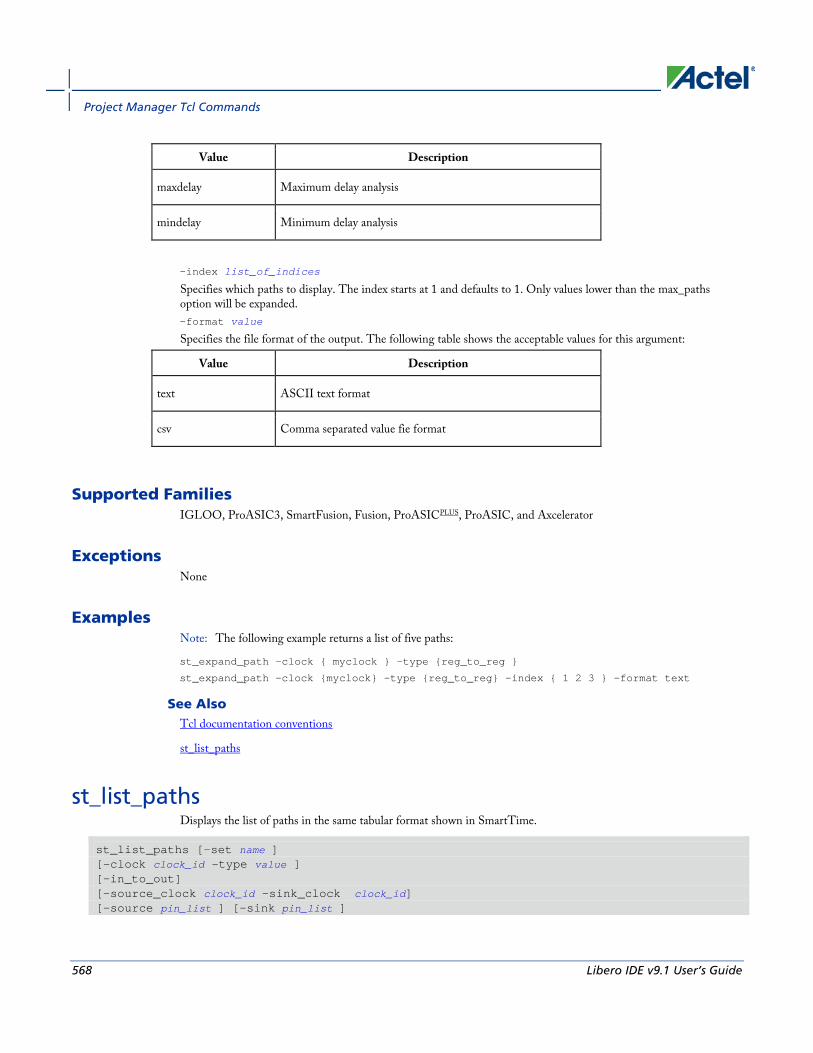
Project Manager Tcl Commands
568 Libero IDE v9.1 User’s Guide
Value Description
maxdelay Maximum delay analysis
mindelay Minimum delay analysis
-index list_of_indices
Specifies which paths to display. The index starts at 1 and defaults to 1. Only values lower than the max_paths option will be expanded. -format value
Specifies the file format of the output. The following table shows the acceptable values for this argument:
Value Description
text ASCII text format
csv Comma separated value fie format
Supported Families IGLOO, ProASIC3, SmartFusion, Fusion, ProASICPLUS, ProASIC, and Axcelerator
Exceptions None
Examples Note: The following example returns a list of five paths:
st_expand_path –clock { myclock } –type {reg_to_reg }
st_expand_path –clock {myclock} –type {reg_to_reg} –index { 1 2 3 } –format text
See Also Tcl documentation conventions
st_list_paths
st_list_paths Displays the list of paths in the same tabular format shown in SmartTime.
st_list_paths [-set name ] [-clock clock_id -type value ] [-in_to_out] [-source_clock clock_id -sink_clock clock_id] [-source pin_list ] [-sink pin_list ]

st_list_paths
Libero IDE v9.1 User’s Guide 569
[-analysis value ] [-format value ]
Arguments -set name
Displays a list of paths from the named set. You can either use the –set option to specify a set name, or use both –clock and –type to specify a set. A list of valid set names includes “in_to_out”, as well as any user set names. -clock clock_id
Displays the set of paths belonging to the specified clock domain. You can either use this option along with -type to specify a set or use the -set option to specify the name of the set to display. -in_to_out
Specifies that the paths should be from the set “Input to Output”, which includes paths that start at input ports and end at output ports. -type value
Specifies the type of paths in the clock domain to display in a list. You can only use this option with the -clock option, not by itself. You can either use this option along with -clock to specify a set or use the -set option to specify a set name.
Value Description
reg_to_reg Paths between registers in the design
async_to_reg Paths from asynchronous pins to registers
reg_to_asyn Paths from registers to asynchronous pins
external_recovery The set of paths from inputs to asynchronous pins
external_removal The set of paths from inputs to asynchronous pins
external_setup Paths from input ports to registers
Paths from input ports to registers
clock_to_out Paths from registers to output ports
-source_clock clock_id
Displays a list of timing paths for an inter-clock domain set belonging to the source clock specified. You can only use this option with the -sink_clock option, not by itself. -sink_clock clock_id
Displays a list of timing paths for an inter-clock domain set belonging to the sink clock specified. You can only use this option with the -source_clock option, not by itself. -source pin_list
Specifies a filter on the source pins of the paths to be listed. -sink pin_list
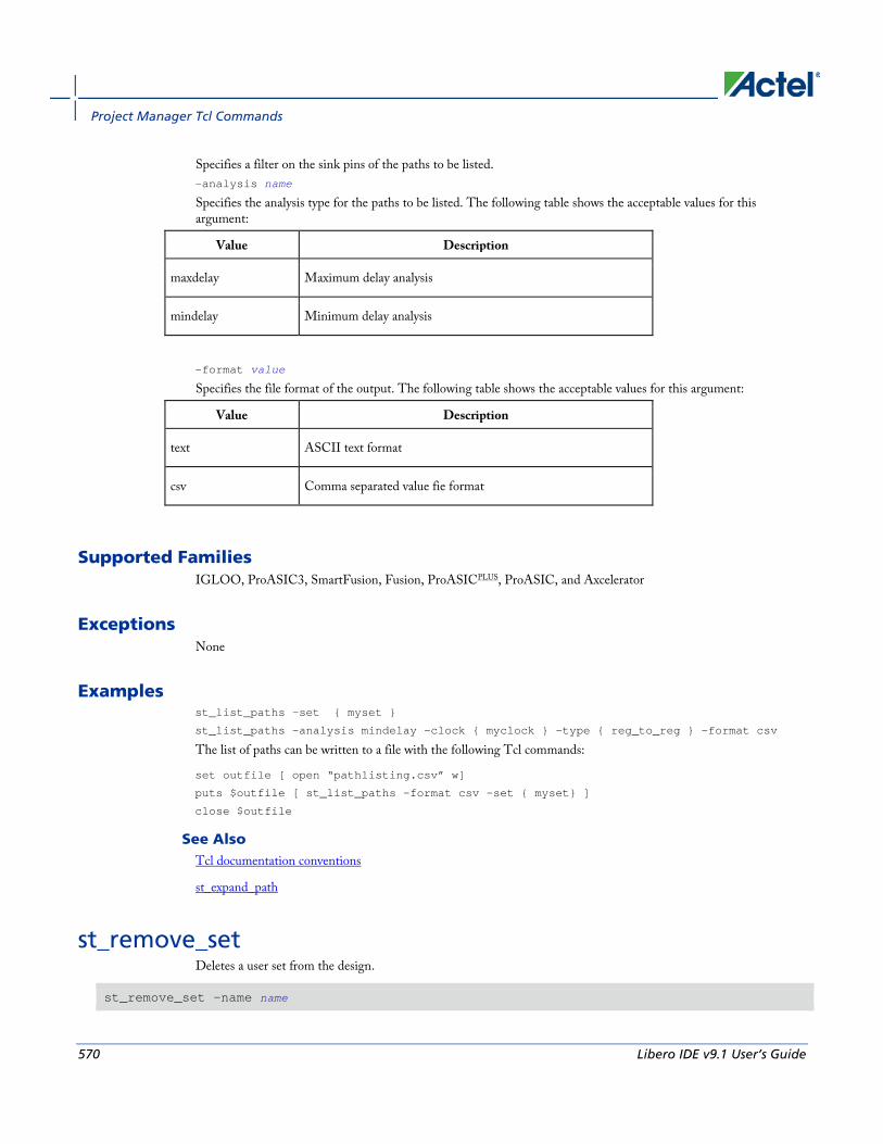
Project Manager Tcl Commands
570 Libero IDE v9.1 User’s Guide
Specifies a filter on the sink pins of the paths to be listed. -analysis name
Specifies the analysis type for the paths to be listed. The following table shows the acceptable values for this argument:
Value Description
maxdelay Maximum delay analysis
mindelay Minimum delay analysis
-format value
Specifies the file format of the output. The following table shows the acceptable values for this argument:
Value Description
text ASCII text format
csv Comma separated value fie format
Supported Families IGLOO, ProASIC3, SmartFusion, Fusion, ProASICPLUS, ProASIC, and Axcelerator
Exceptions None
Examples st_list_paths –set { myset }
st_list_paths –analysis mindelay –clock { myclock } –type { reg_to_reg } –format csv
The list of paths can be written to a file with the following Tcl commands:
set outfile [ open “pathlisting.csv” w]
puts $outfile [ st_list_paths –format csv –set { myset} ]
close $outfile
See Also Tcl documentation conventions
st_expand_path
st_remove_set Deletes a user set from the design.
st_remove_set -name name

st_restore
Libero IDE v9.1 User’s Guide 571
Arguments -name name
Specifies the name of the set to delete.
Supported Families IGLOO, ProASIC3, SmartFusion, Fusion, ProASICPLUS, ProASIC, and Axcelerator
Exceptions None
Examples st_remove_set { clockset1 }
See Also Tcl documentation conventions
st_create_set
st_restore Restores constraints previously committed in SmartTime.
st_restore
Arguments None
Supported Families IGLOO, ProASIC3, SmartFusion, Fusion, ProASICPLUS, ProASIC, Axcelerator, eX, and SX-A
Exceptions None
Examples st_restore
See Also st_commit
Tcl documentation conventions

Project Manager Tcl Commands
572 Libero IDE v9.1 User’s Guide
st_set_options Sets options for timing analysis. With no parameters given, it will display the current settings of the options. For IGLOO, ProASIC3, SmartFusion, Fusion, ProASICPLUS, and Axcelerator families, these options also affect timing-driven place-and-route.
st_set_options [-max_opcond value ] [-min_opcond value] [-interclockdomain_analysis value] [-use_bibuf_loopbacks value] [-enable_recovery_removal_checks value] [-break_at_async value] [-filter_when_slack_below value] [-filter_when_slack_above value] [-remove_slack_filters] [-limit_max_paths value] [-expand_clock_network value] [-expand_parallel_paths value] [-analysis_scenario value] [-tdpr_scenario value] [-reset]
Arguments -max_opcond value
Sets the operating condition to use for Maximum Delay Analysis. The following table shows the acceptable values for this argument:
Value Description
worst Use Worst Case conditions for Maximum Delay Analysis
typ Use Typical conditions for Maximum Delay Analysis
best Use Best Case conditions for Maximum Delay Analysis
-min_opcond value
Sets the operating condition to use for Minimum Delay Analysis. The following table shows the acceptable values for this argument:
Value Description
best Use Best Case conditions for Minimum Delay Analysis
typ Use Typical conditions for Minimum Delay Analysis
worst Use Worst Case conditions for Minimum Delay Analysis

st_set_options
Libero IDE v9.1 User’s Guide 573
-interclockdomain_analysis value
Enables or disables inter-clock domain analysis.
Value Description
yes Enables inter-clock domain analysis
no Disables inter-clock domain analysis
-use_bibuf_loopbacks value
Enables or disables loopback in bibufs.
Value Description
yes Enables loopback in bibufs
no Disables loopback in bibufs
-enable_recovery_removal_checks value
Enables or disables recovery and removal checks.
Value Description
yes Enables recovery and removal checks
no Disables recovery and removal checks
-break_at_async value
Enables or disables breaking paths at asynchronous ports.
Value Description
yes Enables breaking paths at asynchronous ports
no Disables breaking paths at asynchronous ports
-filter_when_slack_below value
Do not show paths with slack below x. -filter_when_slack_above value
Do not show paths with slack above y. -remove_slack_filters
Remove all existing slack filters.

Project Manager Tcl Commands
574 Libero IDE v9.1 User’s Guide
-limit_max_paths value
Limit path reporting commands to a maximum of <n> paths, where n is a value of 0 or higher. -expand_clock_network value
Enables or disables expanded clock network information in expanded paths.
Value Description
yes Enables expanded clock network information in paths
no Disables expanded clock network information in paths
-expand_parallel_paths value
Expand a maximum of <n> parallel paths, where n is a value of 0 or higher. If n is 0 or 1, only one path will be expanded when viewing expanded paths. -analysis_scenario value
Set the timing constraints scenario to be used for both maximum delay and minimum delay analysis. The argument must be a valid scenario name.
Note: Note: This option does not affect the timing scenario used for TDPR.
-tdpr_scenario value
Set the timing constraints scenario to be used by the place and route engine. The argument must be a valid scenario name.
Note: Note: This option does not affect the timing scenario used for analysis.
-reset
Reset all options to their default values, except for scenarios used for analysis and TDPR that remain unchanged.
Supported Families IGLOO, ProASIC3, SmartFusion, Fusion, ProASICPLUS, ProASIC, Axcelerator, eX, and SX-A
Exceptions None
Examples st_set_options –max_opcond worst \
-min_opcond best \
-interclockdomain_analysis true \
-enable_removal_recovery_checks true
st_set_options –limit_max_paths 50 –remove_slack_filters \
–filter_when_slack_above 3
See Also Tcl documentation conventions

timer_add_clock_exception
Libero IDE v9.1 User’s Guide 575
timer_add_clock_exception Adds an exception to or from a pin with respect to a specified clock.
timer_add_clock_exception -clock clock_name -pin pin_name -dir value
Arguments -clock span class="tcl_value"clock_name
Specifies the name of the clock. -pin pin_name
Specifies the exception on the pin in a synchronous network to be excluded from the specified clock period. -dir value
Specifies direction.
Value Description
from Refers to paths starting at the specific pin.
to Refers to paths ending at the specific pin.
Supported Families All
Exceptions • For the IGLOO, ProASIC3, SmartFusion, Fusion, ProASICPLUS, ProASIC, Axcelerator, eX, and SX-
Afamilies, the timing analysis tool translates this command to an equivalent SDC command set_muliticycle_path.
Examples The following example adds a clock exception from the pin reg_q_a_10_/U0:CLK with respect to the clock clk.
timer_add_clock_exception -clock {clk} -pin {reg_q_a_10_/U0:CLK} -dir {from}
The following example adds a clock exception to the pin reg_q_a_10_/U0:E with respect to the clock clk.
timer_add_clock_exception -clock {clk} -pin {reg_q_a_10_/U0:E} -dir {to}
See Also timer_remove_clock_exception
set_multicycle_path
Tcl documentation conventions
timer_add_pass Adds a pin to the list of pins that the path must be shown passing through in the timing analysis tool.

Project Manager Tcl Commands
576 Libero IDE v9.1 User’s Guide
timer_add_pass -pin pin_name
Arguments -pin pin_name
Specifies the name of the pin to be included for displaying the timing path through it.
Supported Families All
Description When you set a pass on a module pin, you can see a path through individual pins.
Exceptions • For the IGLOO, ProASIC3, SmartFusion, Fusion, ProASICPLUS, ProASIC, Axcelerator, eX, and SX-A
families, the timing analysis tool ignores the timer_add_pass command.
Examples This example adds a pass through the pin "reg_q_a_0_:CLK":
>timer_add_pass -pin {reg_q_a_0_:CLK}
This example adds a pass through a clear pin "reg_q_a_0_:CLR":
timer_add_pass -pin {reg_q_a_0_:CLR}
See Also timer_add_stop
Tcl documentation conventions
timer_add_stop Adds the specified pin to the list of pins through which the paths will not be displayed in the timing analysis tool.
timer_add_stop -pin pin_name
Arguments -pin pin_name
Specifies the name of the pin through which the path will not be displayed.
Supported Families All

timer_commit
Libero IDE v9.1 User’s Guide 577
Description Without stop points, you see all paths from pad to pad in the design. If you do not want to see the paths going through register clock pins, you can specify these as stop points. The path going through the specified pins will not be displayed.
Exceptions • For the IGLOO, ProASIC3, SmartFusion, Fusion, ProASICPLUS, ProASIC, Axcelerator, eX, and SX-A
families, Actel recommends that you use the equivalent SDC command set_false_path.
Examples The following example adds a stop to the pin "a<2>":
timer_add_stop -pin {a<2>}
The following example adds a stop to a clock and the clear pin "reg_q_a_0_:CLR":
timer_add_stop -pin {reg_q_a_0_:CLK}
timer_add_stop -pin {reg_q_a_0_:CLR}
See Also timer_add_pass
set_false_path (SDC false path constraint)
Tcl documentation conventions
timer_commit Saves the changes made to constraints into the Designer database.
timer_commit
Arguments None
Supported Families All
Exceptions • For theIGLOO, ProASIC3, SmartFusion, Fusion, ProASICPLUS, ProASIC, Axcelerator, eX, and SX-A
families, Actel recommends that you use import_source . This automatically commits constraints to the design database.
Examples timer_commit

Project Manager Tcl Commands
578 Libero IDE v9.1 User’s Guide
See Also import_source
timer_restore
Tcl documentation conventions
timer_get_path Displays the path between the specified pins in the Log window.
timer_get_path -from source_pin -to destination_pin [-exp value]\ [-sort value]\ [-order value]\ [-case value]\ [-maxpath maximum_paths]\ [-maxexpath maximum_paths_to_expand]\ [-mindelay minimum_delay]\ [-maxdelay maximum_delay]\ [-breakatclk value]\ [-breakatclr value]
Arguments -from source_pin
Specifies the name of the source pin for the path. -to destination_pin
Specifies the name of the destination pin for the path. -exp value
Specifies whether to expand the path. The following table shows the acceptable values for this argument:
Value Description
yes Expands the path
no Does not expand the path
-sort value
Specifies whether to sort the path by either the actual delay or slack value. The following table shows the acceptable values for this argument:
Value Description
actual Sorts the path by the actual delay value
slack Sorts the path by the slack value
-order value
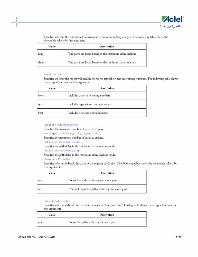
timer_get_path
Libero IDE v9.1 User’s Guide 579
Specifies whether the list is based on maximum or minimum delay analysis. The following table shows the acceptable values for this argument:
Value Description
long The paths are listed based on the maximum delay analysis
short The paths are listed based on the minimum delay analysis
-case value
Specifies whether the report will include the worst, typical, or best case timing numbers. The following table shows the acceptable values for this argument:
Value Description
worst Includes worst case timing numbers
typ Includes typical case timing numbers
best Includes best case timing numbers
-maxpath maximum_paths
Specifies the maximum number of paths to display. -maxexpath maximum_paths_to_expand
Specifies the maximum number of paths to expand. -mindelay minimum_delay
Specifies the path delay in the minimum delay analysis mode. -maxdelay maximum_delay
Specifies the path delay in the maximum delay analysis mode. -breakatclk value
Specifies whether to break the paths at the register clock pins. The following table shows the acceptable values for this argument:
Value Description
yes Breaks the paths at the register clock pins
no Does not break the paths at the register clock pins
-breakatclr value
Specifies whether to break the paths at the register clear pins. The following table shows the acceptable values for this argument:
Value Description
yes Breaks the paths at the register clear pins

Project Manager Tcl Commands
580 Libero IDE v9.1 User’s Guide
Value Description
no Does not break the paths at the register clear pins
Supported Families All
Exceptions None
Examples The following example returns the paths from input port headdr_dat<31> to the input pin of register u0_headdr_data1_reg/data_out_t_31 under typical conditions.
timer_get_path -from "headdr_dat<31>" \
-to "u0_headdr_data1_reg/data_out_t_31/U0:D" \
-case typ \
-exp "yes" \
-maxpath "100" \
-maxexpapth "10"
The following example returns the paths from the clock pin of register gearbox_inst/bits64_out_reg<55> to the output port pma_tx_data_64bit[55]
timer_get_path -from "gearbox_inst/bits64_out_reg<55>/U0:CLK" \
-to {pma_tx_data_64bit[55]} \
-exp "yes"
See Also Tcl documentation conventions
timer_get_clock_actuals Displays the actual clock frequency in the Log window, when the timing analysis tool is initiated.
timer_get_clock_actuals -clock clock_name
Arguments -clock clock_name
Specifies the name of the clock with the frequency (or period) to display.
Supported Families All
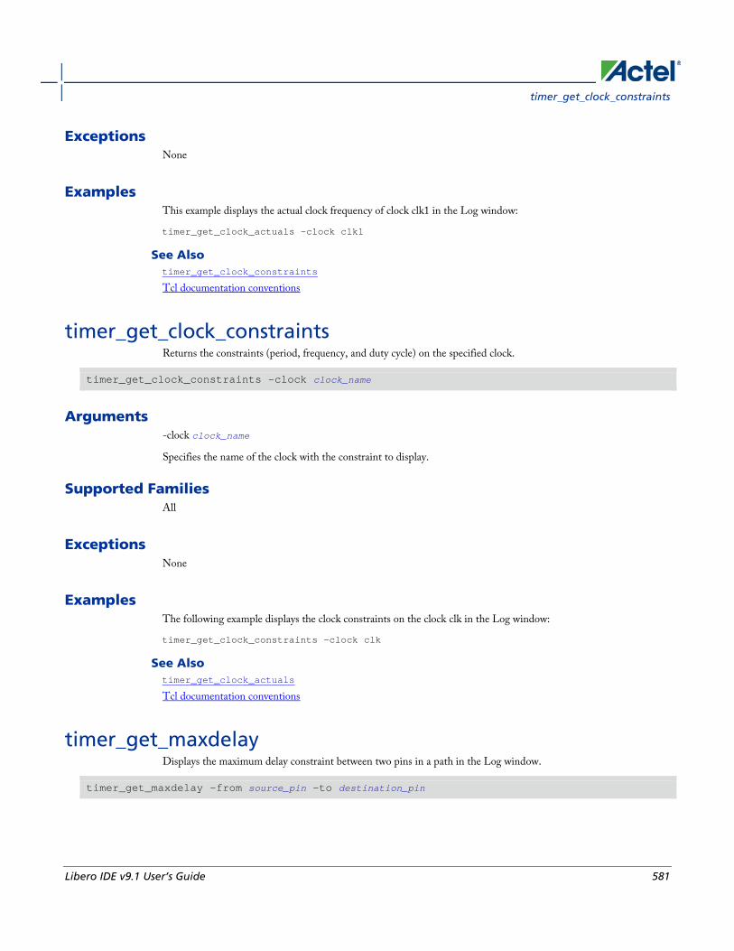
timer_get_clock_constraints
Libero IDE v9.1 User’s Guide 581
Exceptions None
Examples This example displays the actual clock frequency of clock clk1 in the Log window:
timer_get_clock_actuals -clock clk1
See Also timer_get_clock_constraints
Tcl documentation conventions
timer_get_clock_constraints Returns the constraints (period, frequency, and duty cycle) on the specified clock.
timer_get_clock_constraints -clock clock_name
Arguments -clock clock_name
Specifies the name of the clock with the constraint to display.
Supported Families All
Exceptions None
Examples The following example displays the clock constraints on the clock clk in the Log window:
timer_get_clock_constraints -clock clk
See Also timer_get_clock_actuals
Tcl documentation conventions
timer_get_maxdelay Displays the maximum delay constraint between two pins in a path in the Log window.
timer_get_maxdelay -from source_pin -to destination_pin
Project Manager Tcl Commands
582 Libero IDE v9.1 User’s Guide
Arguments -from source_pin
Specifies the name of the source pin in the path. -to destination_pin
Specifies the name of the destination pin in the path.
Supported Families All
Exceptions None
Examples The following example displays the maximum delay constraint from the pin clk166 to the pin reg_q_a_9_/U0:CLK in the Log window:
timer_get_maxdelay -from {clk166} -to {reg_q_a_9_/U0:CLK}
See Also timer_set_maxdelay
Tcl documentation conventions
timer_get_path_constraints Displays the path constraints that were set as the maximum delay constraint in the timing analysis tool.
timer_get_path_constraints
Arguments None
Supported Families All
Description This command lists the paths constrained by maximum delay values. The information is displayed in the Log window. If no maximum delay constraints are set, this command does not report anything.
Exceptions None
timer_remove_clock_exception
Libero IDE v9.1 User’s Guide 583
Examples Invoking timer_get_path_constraints displays the following paths and their delay constraints in the Log window:
max_delay -from [all_inputs] -to [all_outputs] = 12 ns
max_delay -from p_f_testwdata0 p_f_testwdata1 -to p_f_dacuwdata0 p_f_dacuwdata1 r_f_dacuwdata0 r_f_dacuwdata1 = 8 ns
See Also timer_set_maxdelay
Tcl documentation conventions
timer_remove_clock_exception Removes the previously set clock constraint.
timer_remove_clock_exception -clock clock_name -pin pin_name -dir value
Arguments -clock clock_name
Specifies the name of the clock from which to remove the constraint. -pin pin_name
Specifies the name of the pin to remove. -dir value
Specifies direction.
Value Description
from Refers to paths starting at the specified pin.
to Refers to paths ending at the specified pin.
Supported Families All
Exceptions • For the IGLOO, ProASIC3, SmartFusion, Fusion, ProASICPLUS, ProASIC, Axcelerator, eX, and SX-A
families, the timing analysis tool ignores the timer_remove_clock_exceptions command. To remove the clock exception, use the Set Multicycle Constraint dialog box.
Examples This example removes a clock exception from the pin reg_q_a_10_/U0:CLK with respect to the clock clk:
timer_remove_clock_exception -clock {clk} -pin {reg_q_a_10_/U0:CLK} -dir {from}
This example removes a clock exception to the pin reg_q_a_10_/U0:E with respect to the clock clk:
Project Manager Tcl Commands
584 Libero IDE v9.1 User’s Guide
timer_remove_clock_exception -clock {clk} -pin {reg_q_a_10_/U0:E} -dir {to}.
See Also timer_add_clock_exception
Tcl documentation conventions
Set Multicycle Constraint dialog box
timer_remove_pass Removes the previously entered path pass constraint.
timer_remove_pass -pin pin_name
Arguments -pin pin_name
Specifies the name of the pin from which to remove the path pass constraint.
Supported Families All
Exceptions • For the IGLOO, ProASIC3, SmartFusion, Fusion, ProASICPLUS, ProASIC, Axcelerator, eX, and SX-A
families, the timing analysis tool ignores the timer_remove_pass command.
Examples The following example removes the pass constraint from the clock pin reg_q_a_0_:CLK:
timer_remove_pass -pin {reg_q_a_0_:CLK}
See Also timer_add_pass
Tcl documentation conventions
timer_remove_stop Removes the previously entered path stop constraint on the specified pin.
timer_remove_stop -pin pin_name
Arguments -pin pin_name
Specifies the name of the pin from which to remove the path stop constraint.
timer_restore
Libero IDE v9.1 User’s Guide 585
Supported Families All
Description If you remove a path stop constraint using the Timer GUI, and then export a script using File > Export > Script files, the resulting script will contain timer_remove_pass -pin pin_name instead of timer_remove_stop -pin pin_name.
Exceptions • For the IGLOO, ProASIC3, SmartFusion, Fusion, ProASICPLUS, ProASIC, Axcelerator, eX, and SX-A
families, Actel recommends the following flow:
1. Open SmartTime > Set False Path Constraint dialog box.
2. Look for the pin name in the Through: list (Note: You must not have any entry selected in the From or To lists).
3. Delete this pin.
Examples The following example removes the path stop constraint on the clear pin reg_q_a_0_:CLR:
timer_remove_stop -pin {reg_q_a_0_:CLR}
See Also timer_add_stop
Tcl documentation conventions
Set False Path Constraint dialog box
timer_restore Restores constraints previously committed in Timer.
timer_restore
Arguments None
Supported Families All
Exceptions None

Project Manager Tcl Commands
586 Libero IDE v9.1 User’s Guide
Examples timer_restore
See Also timer_commit
Tcl documentation conventions
timer_setenv_clock_freq Sets a required clock frequency for the specified clock in megahertz (MHz).
timer_setenv_clock_freq -clock clock_name -freq value [-dutycycle dutycycle]
Arguments -clock clock_name
Specifies the name of the clock for which to set the required frequency. -freq value
Specifies the frequency in MHz. -dutycycle dutycycle
Specifies the duty cycle for the clock constraint.
Supported Families All
Exceptions • For the IGLOO, ProASIC3, SmartFusion, Fusion, ProASICPLUS, ProASIC, Axcelerator, SX-S, SX-A, and eX
families, Actel recommends that you use the equivalent SDC command create_clock.
Examples The following example sets a clock frequency of 100MHz on the clock clk1:
timer_setenv_clock_freq -clock {clk1} -freq 100.00
See Also create_clock (SDC clock constraint)
Tcl documentation conventions
timer_setenv_clock_period
timer_setenv_clock_period Sets the clock period constraint on the specified clock.

timer_set_maxdelay
Libero IDE v9.1 User’s Guide 587
timer_setenv_clock_period -clock clock_name \ [-unit {value}] -period period_value\ [-dutycycle dutycycle]
Arguments -clock clock_name
Specifies the name of the clock for which to set the period. -unit {value}
Specifies the unit for the clock period constraint. The default is ns. The following table shows the acceptable values for this argument:
Value Description
ns nanoseconds
ps picoseconds
-period period_value
Specifies the period in the specified unit. -dutycycle dutycycle
Specifies the duty cycle for the clock constraint.
Supported Families All
Exceptions • For the IGLOO, ProASIC3, SmartFusion, Fusion, ProASICPLUS, ProASIC, Axcelerator, SX-S, SX-A, and eX
families, Actel recommends that you use the equivalent SDC command create_clock.
Examples The following example sets a clock period of 2.40ns on the clock clk1:
timer_setenv_clock_period -clock clk1 -unit {ns} -period 2.40
See Also timer_setenv_clock_freq
Tcl documentation conventions
timer_set_maxdelay Adds a maximum delay constraint to the specified path.
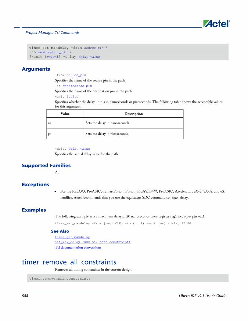
Project Manager Tcl Commands
588 Libero IDE v9.1 User’s Guide
timer_set_maxdelay -from source_pin \ -to destination_pin \ [-unit {value}] -delay delay_value
Arguments -from source_pin
Specifies the name of the source pin in the path. -to destination_pin
Specifies the name of the destination pin in the path. -unit {value}
Specifies whether the delay unit is in nanoseconds or picoseconds. The following table shows the acceptable values for this argument:
Value Description
ns Sets the delay in nanoseconds
ps Sets the delay in picoseconds
-delay delay_value
Specifies the actual delay value for the path.
Supported Families All
Exceptions • For the IGLOO, ProASIC3, SmartFusion, Fusion, ProASICPLUS, ProASIC, Axcelerator, SX-S, SX-A, and eX
families, Actel recommends that you use the equivalent SDC command set_max_delay.
Examples The following example sets a maximum delay of 20 nanoseconds from register reg1 to output pin out1:
timer_set_maxdelay -from {reg1:CLK} -to {out1} -unit {ns} -delay 20.00
See Also timer_get_maxdelay
set_max_delay (SDC max path constraint)
Tcl documentation conventions
timer_remove_all_constraints Removes all timing constraints in the current design.
timer_remove_all_constraints

use_file
Libero IDE v9.1 User’s Guide 589
Arguments None
Supported Families All
Exceptions None
Examples The following example removes all of the constraints from the design and then commits the changes:
timer_remove_all_constraints
timer_commit
See Also timer_commit
Tcl documentation conventions
use_file Specifies which file in your project to use.
use_file -file value -module value -designer_view value
Arguments -filevalue
Specifies the EDIF or ADB file you wish to use in the project. Value is the name of the file you wish use (including the full pathname). -module value
Specifies the module in which you want to use the file. -designer_view value
Specifies the Designer View in which you wish to use the file.
Supported Families All
Exceptions • None

Project Manager Tcl Commands
590 Libero IDE v9.1 User’s Guide
Example Specify file1.edn in the ./project/synthesis directory, in the module named top, in the Designer View named impl1.
use_file –file “./project/synthesis/file1.edn” –module “top” –designer_view “Impl1”
See Also use_source_file
use_source_file Defines a module for your project.
use_source_file -file value -module value
Arguments -file value
Specifies the Verilog or VHDL file. Value is the name of the file you wish use (including the full pathname). -module value
Specifies the module in which you want to use the file.
Supported Families All
Exceptions None
Example Specify file1.vhd in the ./project/hdl directory, in the module named top.
use_source_file –file “./project/hdl/file1.vhd” –module “top"
See Also use_file
Add or Edit profile Dialog Box Use the Add or Edit profile dialog box to add a new tool or edit an existing tool profile.
This dialog box is read-only for predefined profiles.
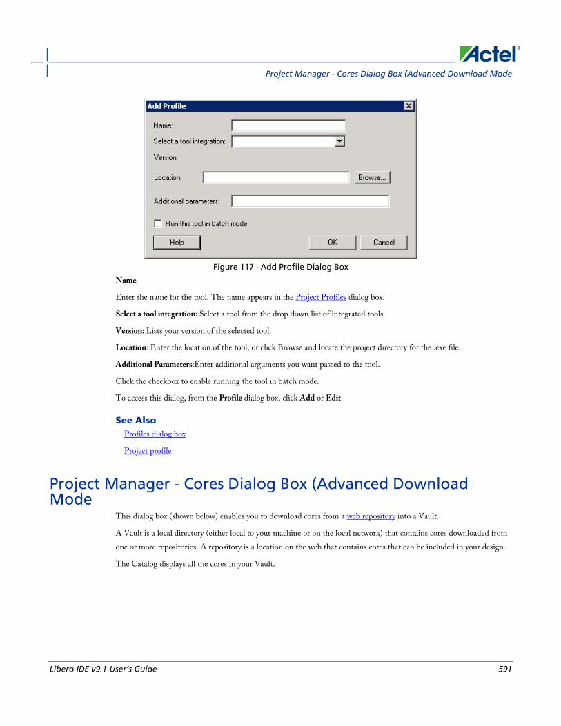
Project Manager - Cores Dialog Box (Advanced Download Mode
Libero IDE v9.1 User’s Guide 591
Figure 117 · Add Profile Dialog Box
Name
Enter the name for the tool. The name appears in the Project Profiles dialog box.
Select a tool integration: Select a tool from the drop down list of integrated tools.
Version: Lists your version of the selected tool.
Location: Enter the location of the tool, or click Browse and locate the project directory for the .exe file.
Additional Parameters:Enter additional arguments you want passed to the tool.
Click the checkbox to enable running the tool in batch mode.
To access this dialog, from the Profile dialog box, click Add or Edit.
See Also Profiles dialog box
Project profile
Project Manager - Cores Dialog Box (Advanced Download Mode
This dialog box (shown below) enables you to download cores from a web repository into a Vault.
A Vault is a local directory (either local to your machine or on the local network) that contains cores downloaded from one or more repositories. A repository is a location on the web that contains cores that can be included in your design.
The Catalog displays all the cores in your Vault.
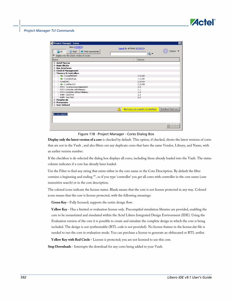
Project Manager Tcl Commands
592 Libero IDE v9.1 User’s Guide
Figure 118 · Project Manager - Cores Dialog Box
Display only the latest version of a core is checked by default. This option, if checked, shows the latest versions of cores that are not in the Vault , and also filters out any duplicate cores that have the same Vendor, Library, and Name, with an earlier version number.
If the checkbox is de-selected the dialog box displays all cores, including those already loaded into the Vault. The status column indicates if a core has already been loaded.
Use the Filter to find any string that exists either in the core name or the Core Description. By default the filter contains a beginning and ending ‘*’, so if you type ‘controller’ you get all cores with controller in the core name (case insensitive search) or in the core description.
The colored icons indicate the license status. Blank means that the core is not license protected in any way. Colored icons means that the core is license protected, with the following meanings:
Green Key - Fully licensed; supports the entire design flow.
Yellow Key - Has a limited or evaluation license only. Precompiled simulation libraries are provided, enabling the core to be instantiated and simulated within the Actel Libero Integrated Design Environment (IDE). Using the Evaluation version of the core it is possible to create and simulate the complete design in which the core is being included. The design is not synthesizable (RTL code is not provided). No license feature in the license.dat file is needed to run the core in evaluation mode. You can purchase a license to generate an obfuscated or RTL netlist.
Yellow Key with Red Circle - License is protected; you are not licensed to use this core.
Stop Downloads - Interrupts the download for any cores being added to your Vault.

Catalog Options Dialog Box
Libero IDE v9.1 User’s Guide 593
Catalog Options Dialog Box The Catalog Options dialog box (as shown below) enables you to customize your Catalog display. You can add a repository, set the location of your vault, and change the View Settings for the Catalog. To display this dialog box, click
the Catalog Options button .
Figure 119 · Catalog Display Options Dialog Box
Vault/Repositories Settings
Repositories A repository is a location on the web that contains cores that can be included in your design.
The Catalog Options dialog box enables you to specify which repositories you want to display in your Vault. The Vault displays a list of cores from all your repositories, and the Catalog displays all the cores in your Vault.
The default repository cannot be permanently deleted; it is restored each time you open the Manage Repositories dialog box.
Any cores stored in the repository are listed by name in your Vault and Catalog; repository cores displayed in your Catalog can be filtered like any other core.
Type in the address and click the Add button to add new repositories. Click the Remove button to remove a repository (and its contents) from your Vault and Catalog. Removing a repository from the list removes the repository contents from your Vault.
Vault location Use this option to choose a new vault location on your local network. Enter the full domain pathname in the Select new vault location field. Use the format:
\\server\share
and the cores in your Vault will be listed in the Catalog.

Project Manager Tcl Commands
594 Libero IDE v9.1 User’s Guide
View Settings
Display Group cores by function - Displays a list of cores, sorted by function. Click any function to expand the list and view specific cores.
List cores alphabetically - Displays an expanded list of all cores, sorted alphabetically. Double click a core to configure it. This view is often the best option if you are using the filters to customize your display.
Show core version - Shows/hides the core version.
Filters Filter field - Type text in the Filter Field to display only cores that match the text in your filter. For example, to view cores that include 'sub' in the name, set the Filter Field to Name and type sub.
Display only latest version of a core - Shows/hides older versions of cores; this feature is useful if you are designing with an older family and wish to use an older core.
Show all local and remote cores - Displays all cores in your Catalog.
Show local cores only - Displays only the cores in your local vault in your Catalog; omits any remote cores.
Show remote cores that are not in my vault - Displays remote cores that have not been added to your vault in your Catalog.
CDB File Organization Dialog Box The CDB File Organization dialog box manages conflict resolution between the blocks in your design.
It is important to preserve the order of your CDB files if they are interdependent. Use the CDB File Organization dialog box to set the compile order for your CDB files (as shown in the figure below). CDB file organization is a pre-module setting; modifying the CDB order will apply to all ADBs of a given module.

Change All Links Dialog Box
Libero IDE v9.1 User’s Guide 595
Figure 120 · CDB File Organization Dialog Box
Use the up and down arrows to specify the order, or drag the files into order. Select the checkbox to show the dialog before you create a new ADB file.
Change All Links Dialog Box The Change All Links dialog box enables you to update/change all the links for the files in your project at once.
This dialog box is useful when you are linking to shared network folders that may be renamed by other users, or to folders on your local machine that have been renamed.
Figure 121 · Change All Links Dialog Box
Old Path - Location of your old project files. Click the browse button to navigate to the location.
New Path - Location of your new project files. Click the browse button to navigate to the location.

Project Manager Tcl Commands
596 Libero IDE v9.1 User’s Guide
Configure Flow Dialog Box When you click Configure Project Flow in the Project Flow window you can choose to configure the flow for your modules.
Figure 122 · Configure Flow Dialog Box
Configure the flow for all modules General
Preferred HDL Type - Set your preferred HDL type to VHDL or Verilog.
HDL Netlists
The HDL project-level options enable you to specify whether or not you want to generate your HDL netlists after synthesis.
• Generate an HDL netlist immediately after synthesis - Select this option if you run post-synthesis simulation. If you do not run post-synthesis simulation, de-select this option to start Designer more quickly.
DRC
Run DRC immediately after synthesis - This option evaluates the netlist generated by Synplify to ensure it does not have any connection problems.
ModelSim
Update modelsim.ini automatically - May be useful if the Project Manager does not create a valid modelsim.ini file. Click the checkbox to enable.
ViewDraw
Generate HDL netlist after a Save&Check in ViewDraw - Useful if you wish to eliminate the manual step of generating your HDL netlist after a Save&Check.

Convert Project Dialog Box
Libero IDE v9.1 User’s Guide 597
Update viewdraw.ini automatically - May be useful if the Project Manager does not create a valid viewdraw.ini file. Click the checkbox to enable.
File Detection - Detect new files on disk automatically enables the Project Manager to see new files when you add them to your project. If you deselect this option, you must add the new files manually.
Core generation - Generate resource report creates and saves the core resource report after you generate a core.
FlashPro options - Input programming file for FlashPro sets your input programming file. PDB files enable you to configure the security settings in FlashROM and Flash Memory from FlashPro.
Configure the flow for module <module_name> You can also choose to enable or disable synthesis if you are using a structural implementation. Synthesis is required for RTL modules and cannot be disabled.
To view this dialog box, click Configure Flow in the Project Manager Project Flow window.
Convert Project Dialog Box The Convert Project dialog box enables you to create a backup file of your project before you convert the project data to use with your current version of Libero IDE (as shown in the figure below).
Figure 123 · Convert Project Dialog Box
Create a backup of the original project - Creates a backup of your project and saves it as a zip file in the directory you specify. Click the browse button to set the location of the backup file.
Export Profiles Dialog Box Use the Export Profiles dialog box to create an INI file and save your tool profiles.
After you create an INI file, you can import it into other Libero IDE projects.
Specify a filename and click Save, or click Cancel to return to the Project Manager.

Project Manager Tcl Commands
598 Libero IDE v9.1 User’s Guide
Save in
Specifies the director in which to save your exported tool profile. Browse to select a different directory.
File name
Type the file name for your exported tool profile.
Save as type
Specifies the file type displayed in the dialog box. Only INI files are supported for tool profiles.
To access this dialog: from the File menu, choose Export > Profiles.
Import Files Dialog Box (Project Manager) Use the Import Files dialog box to add new files to your project in the Libero IDE Project Manager.
You can import schematics, VHDL or Verilog source files, stimulus files, SDC, PDC, VCD, and SAIF files, cores, and even tool profiles (from other Libero IDE projects).
Browse to and select the file you wish to add and click Import, or click Cancel to return to the Project Manager.
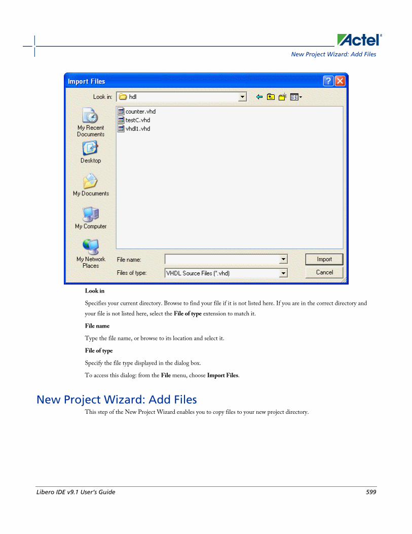
New Project Wizard: Add Files
Libero IDE v9.1 User’s Guide 599
Look in
Specifies your current directory. Browse to find your file if it is not listed here. If you are in the correct directory and your file is not listed here, select the File of type extension to match it.
File name
Type the file name, or browse to its location and select it.
File of type
Specify the file type displayed in the dialog box.
To access this dialog: from the File menu, choose Import Files.
New Project Wizard: Add Files This step of the New Project Wizard enables you to copy files to your new project directory.
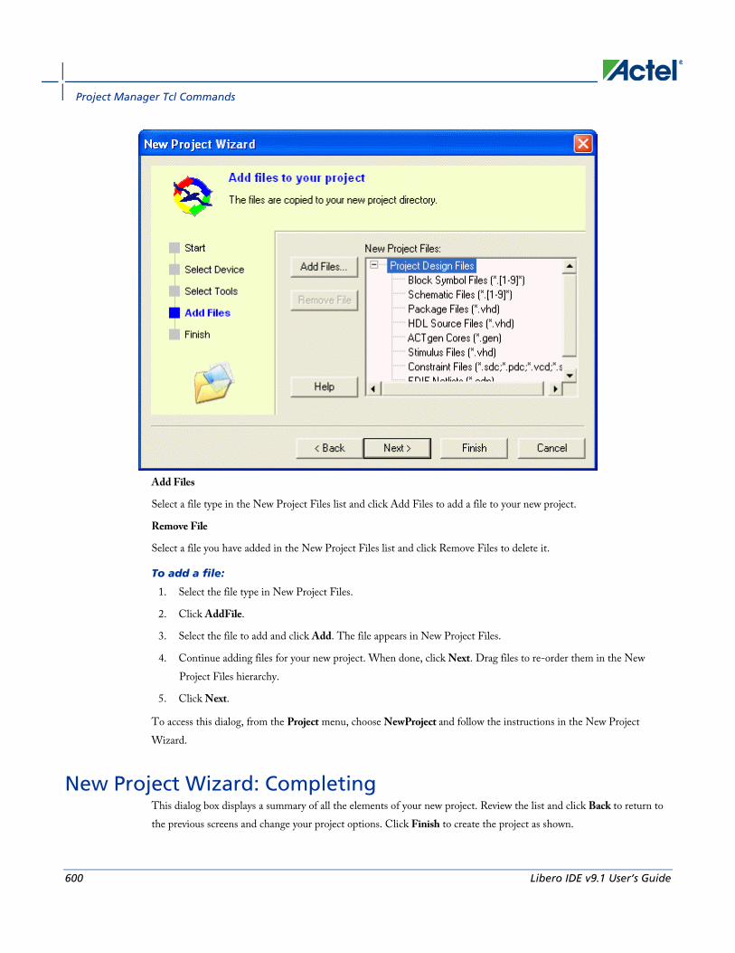
Project Manager Tcl Commands
600 Libero IDE v9.1 User’s Guide
Add Files
Select a file type in the New Project Files list and click Add Files to add a file to your new project.
Remove File
Select a file you have added in the New Project Files list and click Remove Files to delete it.
To add a file:
1. Select the file type in New Project Files.
2. Click AddFile.
3. Select the file to add and click Add. The file appears in New Project Files.
4. Continue adding files for your new project. When done, click Next. Drag files to re-order them in the New Project Files hierarchy.
5. Click Next.
To access this dialog, from the Project menu, choose NewProject and follow the instructions in the New Project Wizard.
New Project Wizard: Completing This dialog box displays a summary of all the elements of your new project. Review the list and click Back to return to the previous screens and change your project options. Click Finish to create the project as shown.
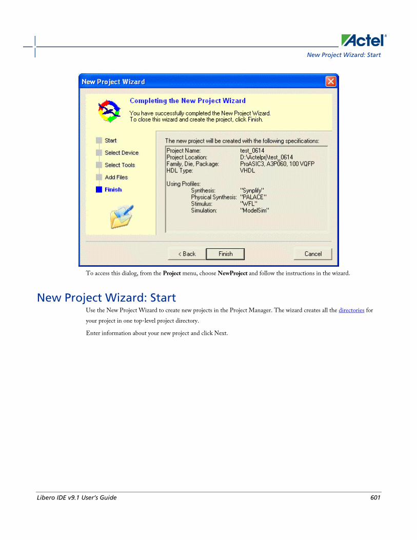
New Project Wizard: Start
Libero IDE v9.1 User’s Guide 601
To access this dialog, from the Project menu, choose NewProject and follow the instructions in the wizard.
New Project Wizard: Start Use the New Project Wizard to create new projects in the Project Manager. The wizard creates all the directories for your project in one top-level project directory.
Enter information about your new project and click Next.

Project Manager Tcl Commands
602 Libero IDE v9.1 User’s Guide
Figure 124 · New Project Wizard Dialog Box - Start
Project Name
Type the project name.
Project Location
Accept the default location or browse to the new location where you can save and store your project. All files for your project are saved in this directory.
Preferred HDL type
Select Verilog or VHDL. Libero IDE supports mixed-HDL design flows.
To access this dialog, from the Project menu, choose New Project.
New Project Wizard: Select Device Select the family device, die, and package you intend to use for your project. You may select a package only after you have selected a family and die.

New Project Wizard: Select Integrated Tools
Libero IDE v9.1 User’s Guide 603
Family
Select your device family from the drop-down menu.
Die
Select the die for your project.
Package
Select the package for your project. The package list varies according to the die you select.
Click Next to add files or Finish to open the new project without importing files.
To access this dialog, from the Project menu, choose New Project and follow the instructions in the New Project Wizard.
New Project Wizard: Select Integrated Tools Select the tools you want integrated with this project. Click Add and select the tool type, or select a tool and click Edit to specify the tool location. The example shows the tools available in the default Libero IDE installation. This dialog box sets your project profile information.
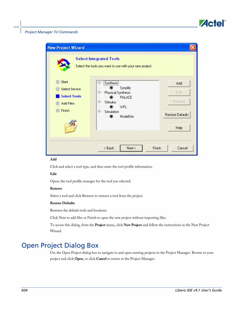
Project Manager Tcl Commands
604 Libero IDE v9.1 User’s Guide
Add
Click and select a tool type, and then enter the tool profile information.
Edit
Opens the tool profile manager for the tool you selected.
Remove
Select a tool and click Remove to remove a tool from the project.
Restore Defaults
Restores the default tools and locations.
Click Next to add files or Finish to open the new project without importing files.
To access this dialog, from the Project menu, click New Project and follow the instructions in the New Project Wizard.
Open Project Dialog Box Use the Open Project dialog box to navigate to and open existing projects in the Project Manager. Browse to your project and click Open, or click Cancel to return to the Project Manager.

Organize Constraints for Synthesis Dialog Box
Libero IDE v9.1 User’s Guide 605
Look in
Specifies the directory that contains your project.
File name
Type the file name, or browse to its location and select it.
File of type
Specify the file type displayed in the dialog box.
To access this dialog: from the Project menu, select Open Project.
Organize Constraints for Synthesis Dialog Box The Organize Constraints for Synthesis dialog box enables you to specify the order of your constraint files in your synthesis tool. Synthesis supports only SDC files.

Project Manager Tcl Commands
606 Libero IDE v9.1 User’s Guide
Figure 125 · Organize Constraints for Synthesis Dialog Box
Constraints files in the project / Origin
Lists all the synthesis constraint files in your current Libero IDE project and the origin of the file.
Constraint files for Synthesis / Origin
Lists the constraint files you have added for synthesis and their origin. The synthesis order proceeds from the top of the list to the bottom. Use the Up and Down arrows to change the order of the files.
Add
Adds files to the Constraint files for Synthesis list in your project.
Remove
Removes files from the Constraint files for Synthesis list in your project.
Up and Down Arrows
Use these buttons to order the stimulus files.
De-select the Show this dialog before running synthesis checkbox if you do not wish to organize your constraints each time you run synthesis.
Organize Stimulus Dialog Box Use the Organize Stimulus dialog box (below) to manage the stimulus files in your project.

Page Setup Dialog Box
Libero IDE v9.1 User’s Guide 607
Figure 126 · Organize Stimulus Files Dialog Box
Stimulus files in the project
Lists all the stimulus files in your current Libero IDE project. In most cases you will only have one testbench associated with your block. However, if you want simultaneous association of multiple testbench files for one simulation session, as in the case of PCI cores, add multiple files to the Associated Files list box.
Associated files
Lists all the files associated with your project.
Add
Adds files to the Associated files list in your project.
Remove
Removes files from the Associated files list in your project.
Up and Down Arrows
Use these buttons to order the stimulus files. The top-level entity should be at the bottom of the list.
Page Setup Dialog Box Use this dialog box to format your page header and footer. The default displays your project file name in the header and the page number of the total number pages (such as "1 of 4") in the footer.

Project Manager Tcl Commands
608 Libero IDE v9.1 User’s Guide
Figure 127 · Page Setup Dialog Box
You can add additional information about your project, such as a project description, the names of team members, or the date you started. To do so, type the information into the Header (or Footer) field.
The Default button resets the fields to their original settings.
Profiles Dialog Box In the Libero IDE project, each user can activate predefined tool profiles (created during Libero IDE’s installation) or custom user tool profiles. You can create new custom user tool profiles if you want to add tools, try a different tool, change to an older or newer version, etc.
For example, if you have an existing Synplify installation and want to use it instead of the Libero IDE default, you can create a custom tool profile and assign it to your custom installation. Your custom Synplify installation is attached to your custom user profile and appears in all your Libero IDE projects.
Figure 128 · Project Profiles Dialog Box

Save Project As Dialog Box
Libero IDE v9.1 User’s Guide 609
You can export and import your custom profiles; this is useful if you wish to share your profiles with someone else. To export, from the File menu choose Export Profiles. To import, from the File menu, choose Import Files and select Tool Profiles as the file type.
Your Profiles dialog box includes predefined system profiles for the Libero IDE tools. Default predefined profiles are locked and cannot be edited or deleted.
A red question mark next to a profile means that the location or version of the tool has changed. If your user profile has a red question mark you can click Edit to specify the location of the tool.
If your system profile shows a red question mark you may have opted not to install that tool during the Libero IDE setup/install. If you are using a different version of the tool you can create a custom profile that points to the correct tool location but you cannot update the default system profile.
Add
Click Add and select which type of tool (synthesis, stimulus, or simulation). Fill out the tool profile and click OK.
Edit
After selecting the tool, click to Edit to select another tool, change the tool name, or change the tool location.
Remove
After selecting a tool, click Remove.
To access this dialog, from the Project menu, choose Profile.
Clone a Profile
Right-click a profile in the Profiles dialog box and choose Clone.
Cloning a profile opens the Add Profile dialog box and populates the fields with the values from the profile you cloned. This is useful if you wish to create a new tool profile based on an existing tool profile and do not wish to re-type the information.
See Also Synplify AE
WaveFormer Pro
ModelSim AE
Save Project As Dialog Box The Save Project As dialog box enables you to save your entire project (Designer views, tool profiles, etc.) with a new name and location. save
Enter the name and location for your modified project and click OK to continue.

Project Manager Tcl Commands
610 Libero IDE v9.1 User’s Guide
Figure 129 · Save Project As Dialog Box
Project Name
Type the project name for your modified project.
Project Location
Accept the default location or Browse to the new location where you can save and store your project. All files for your project are saved in this directory.
Content
Copy Links locally - Select this checkbox to copy the links from your current project into your new project. If you do not select this checkbox, the links will not be copied and you must add them manually.
Files
• Select All - Includes all your project and source files in your new project.
• Project files only - Copies only your project files into your new project (only the files in the Files tab of the Design Explorer).
• Source files only - Copies only your source files into your new project; for example, simulation files are not preserved.
• None - Saves a new empty project.
Designer Views - Select All, Current view, or None to copy your views into your new project.
To access this dialog, from the Project menu, choose Save Project As.
Script Export Options Dialog Box If you export a Tcl script in the Project Manager, the Script Export Options dialog box appears.

Project Manager Project Menu
Libero IDE v9.1 User’s Guide 611
Figure 130 · Script Export Options Dialog Box
Include commands from current project only - Select this option if you want to include all the commands from your current project.
Filename Formatting - Choose Relative filenames if you do not intend to move the Tcl script from the saved location, or Qualified filenames if you plan to move the Tcl script on your machine.
Project Manager Project Menu
Command Sub-menu Icon Function
New Project
Starts the New Project Wizard
Open Project
Opens the Open Project dialog box
Close Project Closes the current active project; the Project Manager remains open
Save Project
Saves the current project
Save Project As
Saves the current project in a new directory; prompts you to enter a new project name
Detect New Detects new files and adds them to the Project
Project Manager Tcl Commands
612 Libero IDE v9.1 User’s Guide
Command Sub-menu Icon Function
Files Manager (if found).
VHDL Library >
Add Add a VHDL library in your project
Remove Remove a VHDL library in your project
Rename Rename a VHDL library in your project
Settings Opens the Project Settings dialog box; enables you to manage device, simulation, and programming options for your project
Profile Opens the Project Profile dialog box; enables you to specify locations for your third-party synthesis, stimulus, and simulation tools. Libero IDE includes tools for synthesis, stimulus, and simulation.
Configure Project Flow
Opens the Configure Flow dialog box, sets options on your HDL netlists, DRC checker, ViewDraw, and a resource report when you generate a core.
File Organization >
Source Files for Synthesis
Opens the Organize Source Files for Synthesis dialog box
Source Files for Simulation
Opens the Organize Source Files for Simulation dialog box
Designer Constraint Files
Opens the Organize Constraints for Designer dialog box; enables you to organize your Designer constraint files in the Project Manager
Designer CDB Files
Opens the CDB File Organization dialog box; the CDB File Organization dialog box manages conflict resolution (if any) between the blocks in your design
Stimulus Opens the Organize Stimulus dialog box; enables you to organize your stimulus files in the Project Manager
Designer Views >
Select Choose your Designer View from the drop down menu. Note that views are listed in they order they

Project Manager File Menu
Libero IDE v9.1 User’s Guide 613
Command Sub-menu Icon Function
were created
Previous
Switches to the previous view
Next
Switches to the next view
Add
Opens the Add Designer View dialog box; enables you to specify the name of your latest view
Remove
Opens Remove Designer View dialog box; enables you to delete all related Designer View files from your disk
Rename
Opens Rename Designer View dialog box; select the Designer View you want to rename and enter the new name
Execute Script Opens Execute Script dialog box; enables you to run Tcl script from the Project Manager
Preferences Opens the Preferences dialog box
Recent Projects Opens list of recent Libero IDE projects.
Exit Closes Project Manager
Project Manager File Menu
Command Icon Shortcut Sub-menu
Function
New
Ctrl + N Opens the Project Manager New file dialog box and prompts you to enter a name and specify a file type
Open
Ctrl + O Opens the Project Manager Open dialog box; enables you to select a file to open
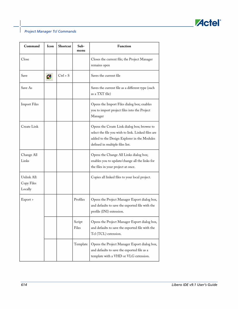
Project Manager Tcl Commands
614 Libero IDE v9.1 User’s Guide
Command Icon Shortcut Sub-menu
Function
Close Closes the current file; the Project Manager remains open
Save
Ctrl + S Saves the current file
Save As Saves the current file as a different type (such as a TXT file)
Import Files Opens the Import Files dialog box; enables you to import project files into the Project Manager
Create Link Opens the Create Link dialog box; browse to select the file you wish to link. Linked files are added to the Design Explorer in the Modules defined in multiple files list.
Change All Links
Opens the Change All Links dialog box; enables you to update/change all the links for the files in your project at once.
Unlink All: Copy Files Locally
Copies all linked files to your local project.
Export > Profiles Opens the Project Manager Export dialog box, and defaults to save the exported file with the profile (INI) extension.
Script Files
Opens the Project Manager Export dialog box, and defaults to save the exported file with the Tcl (TCL) extension.
Template Opens the Project Manager Export dialog box, and defaults to save the exported file as a template with a VHD or VLG extension.
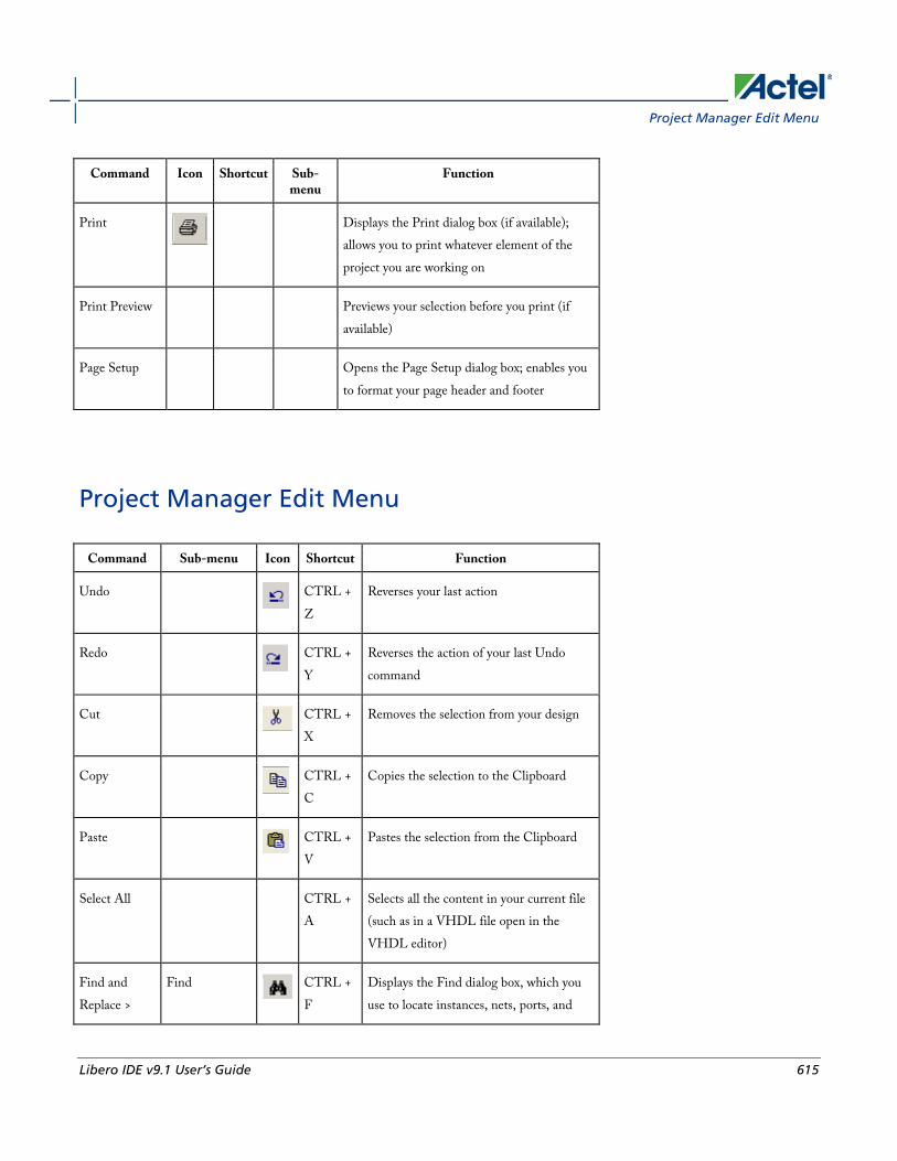
Project Manager Edit Menu
Libero IDE v9.1 User’s Guide 615
Command Icon Shortcut Sub-menu
Function
Displays the Print dialog box (if available); allows you to print whatever element of the project you are working on
Print Preview Previews your selection before you print (if available)
Page Setup Opens the Page Setup dialog box; enables you to format your page header and footer
Project Manager Edit Menu
Command Sub-menu Icon Shortcut Function
Undo
CTRL + Z
Reverses your last action
Redo
CTRL + Y
Reverses the action of your last Undo command
Cut
CTRL + X
Removes the selection from your design
Copy
CTRL + C
Copies the selection to the Clipboard
Paste
CTRL + V
Pastes the selection from the Clipboard
Select All CTRL + A
Selects all the content in your current file (such as in a VHDL file open in the VHDL editor)
Find and Replace >
Find
CTRL + F
Displays the Find dialog box, which you use to locate instances, nets, ports, and

Project Manager Tcl Commands
616 Libero IDE v9.1 User’s Guide
Command Sub-menu Icon Shortcut Function
regions
Find Next
F3 Finds the next occurrence of the text in the Find field
Replace
CTRL + H
Displays the Replace dialog box; enables you to search and replace content in your files (files must be open and selected to use this feature)
Find in Files
Opens the Find in Files dialog box; enables you to search for text in files or directories that you specify
Find Module / Component
Opens the Find Module dialog box;
searches the Libero IDE project for specific entity (module) names
Comment Out
CTRL + M
Inserts comment characters in the selected line (or lines) of your text editor
Uncomment Out
CTRL + K
Removes comment characters from the selected line (or lines) of your text editor
Filter CTRL + R
Refreshes the display
Project Manager View Menu
Command Sub-menu Shortcut Function
Toolbars > Status Bar Shows/hides status bar in Project Manager
Standard Shows/hides standard toolbar in Project Manager
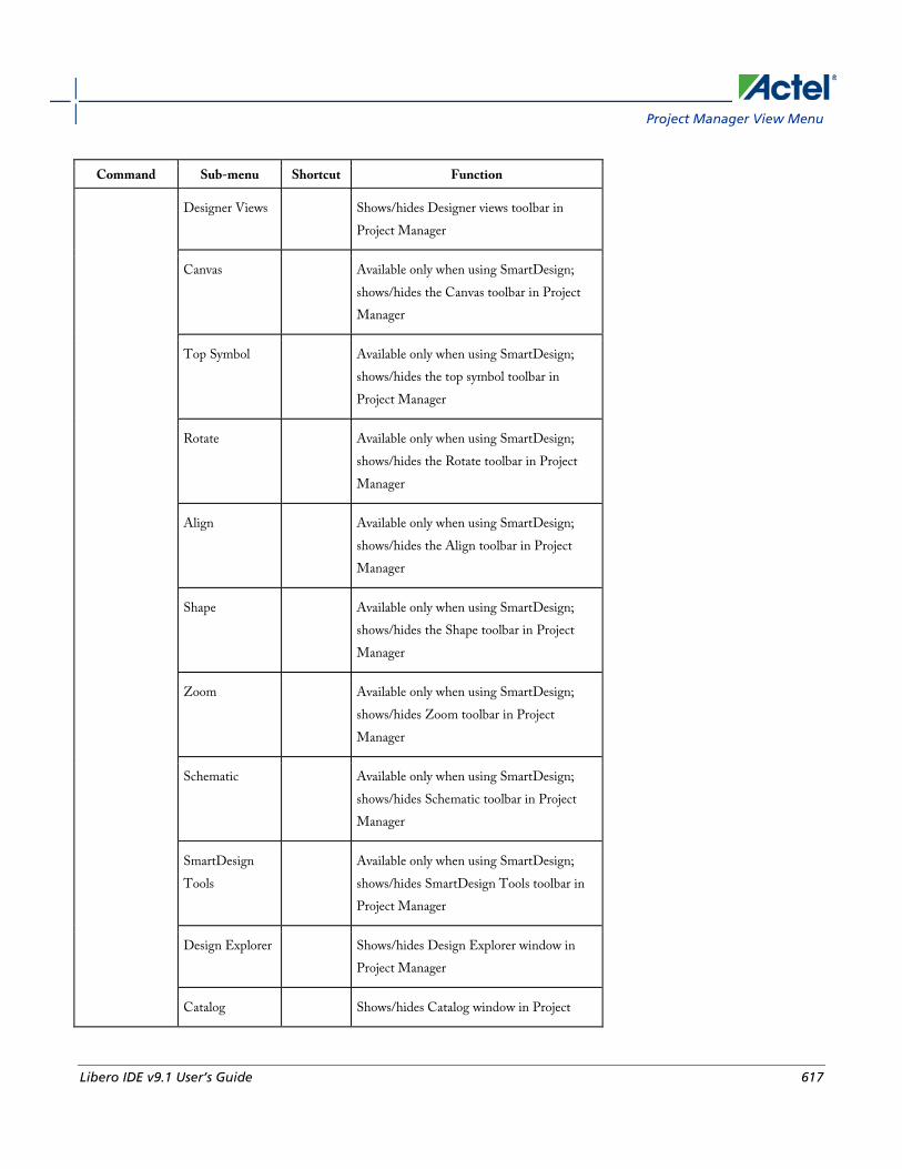
Project Manager View Menu
Libero IDE v9.1 User’s Guide 617
Command Sub-menu Shortcut Function
Designer Views Shows/hides Designer views toolbar in Project Manager
Canvas Available only when using SmartDesign; shows/hides the Canvas toolbar in Project Manager
Top Symbol Available only when using SmartDesign; shows/hides the top symbol toolbar in Project Manager
Rotate Available only when using SmartDesign; shows/hides the Rotate toolbar in Project Manager
Align Available only when using SmartDesign; shows/hides the Align toolbar in Project Manager
Shape Available only when using SmartDesign; shows/hides the Shape toolbar in Project Manager
Zoom Available only when using SmartDesign; shows/hides Zoom toolbar in Project Manager
Schematic Available only when using SmartDesign; shows/hides Schematic toolbar in Project Manager
SmartDesign Tools
Available only when using SmartDesign; shows/hides SmartDesign Tools toolbar in Project Manager
Design Explorer Shows/hides Design Explorer window in Project Manager
Catalog Shows/hides Catalog window in Project

Project Manager Tcl Commands
618 Libero IDE v9.1 User’s Guide
Command Sub-menu Shortcut Function
Manager
Information Window
Shows/hides Information Window in Project Manager
Find Window Shows/hides Find window in Project Manager
Log Window Shows/hides Log window in Project Manager
Configure Information Window
Enables you to show/hide elements in the Information Window, such as lists of new features, or properties of your current project.
Project Flow Window
Shows/hides the Project Flow window in the Project Manager
Bring Project Flow Window to the front
F2 Moves Project Flow window to the front of display; useful if you have several windows open simultaneously.
Refresh Design Hierarchy
CTRL + R
Updates the Hierarchy tab in the Design Explorer window. Useful if you add files to the project and Project Manager does not show them in the Hierarchy.
Reset Window Layout
Returns Project Manager window layout to default.
Maximize Work Area
CTRL+W Hides the Catalog, Log Window, and Design Explorer windows (if open) and expands the selected tab in the Project Flow or SmartDesign work area.
Zoom > Zoom In CTRL + + Zooms into the view in the Project Manager (if enabled)

Project Manager Tools Menu
Libero IDE v9.1 User’s Guide 619
Command Sub-menu Shortcut Function
Zoom Out CTRL + - Zooms out of the view in the Project Manager (if enabled)
Zoom Region CTRL +W
Zooms into a region of the view in the Project Manager (if enabled); click and drag to select a region.
Zoom Fit CTRL + 0 Fits the view into the Project Manager (if enabled)
Pan Scrolls the view in the Project Manager (if enabled)
Project Manager Tools Menu
Command Sub-menu Icon Function
HDL Editor
Opens the New file dialog box and defaults to VHDL entity. Enter a filename and click OK to open the VHDL editor.
SmartDesign
Opens the New file dialog box and defaults to SmartDesign component. Enter a filename and click OK to open SmartDesign.
CoreConsole
Opens the New file dialog box and defaults to CoreConsole component. Enter a filename and click OK to open CoreConsole.
ViewDraw
Opens the New file dialog box and defaults to Schematic. Enter a filename and click OK to open ViewDraw.
ViewDraw > Generate Creates a new EDIF file from the

Project Manager Tcl Commands
620 Libero IDE v9.1 User’s Guide
Command Sub-menu Icon Function
Tools EDIF schematic
Generate HDL
Creates a new HDL file from the schematic
Synplify Synthesis
Starts Synplify
WaveFormer Stimulus
Starts WaveFormer and creates a stimulus file named after your project
ModelSim Simulation
Starts ModelSim AE and opens any existing simulation files in your project
Designer Place-and-Route
Starts Designer; enables you to compile, layout, and analyze your design.
Silicon Sculptor
Starts the Silicon Sculptor programming tool
FlashPro
Starts the FlashPro programming tool
Silicon Explorer Starts the Silicon Explorer debug tool (if available)
Identify Debugger
Opens the Identify Debugger (from Synplify)
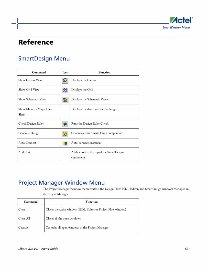
SmartDesign Menu
Libero IDE v9.1 User’s Guide 621
Reference
SmartDesign Menu
Command Icon Function
Show Canvas View
Displays the Canvas
Show Grid View
Displays the Grid
Show Schematic View
Displays the Schematic Viewer
Show Memory Map / Data Sheet
Displays the datasheet for the design
Check Design Rules
Runs the Design Rules Check
Generate Design
Generates your SmartDesign component
Auto Connect
Auto-connects instances
Add Port Adds a port to the top of the SmartDesign component
Project Manager Window Menu The Project Manager Window menu controls the Design Flow, HDL Editor, and SmartDesign windows that open in the Project Manager.
Command Function
Close Closes the active window (HDL Editor or Project Flow window)
Close All Closes all the open windows
Cascade Cascades all open windows in the Project Manager

Reference
622 Libero IDE v9.1 User’s Guide
Command Function
Tile Vertically Tiles all open windows in the Project Manager vertically
Tile Horizontally Tiles all open windows in the Project Manager horizontally
Project Flow Shows project flow window in Project Manager
<*.vhd filename> Shows VHD file, if open, in Project Manager
Project Manager Help Menu The Help menu enables you to access the Libero IDE online help, reference manuals, check for updates, and view your license and version information.
Command Icon Function
Help Topics Opens the Libero Project Manager online help
Reference Manuals
Opens the list of manuals (PDF files) available for Libero Project Manager, including links to library guides, PDF versions of the online help, and information about third party (OEM) tool guides.
Actel Technical Support
Displays the Actel customer support web page in your default browser
Actel Web Site Displays the main Actel page in your default browser
Check for Software Updates
Checks for updates to the Libero Project Manager software
License Details Displays detailed license information for your version of Libero IDE Project Manager
About Libero Project Manager
Displays version and release numbers for Libero IDE Project Manager
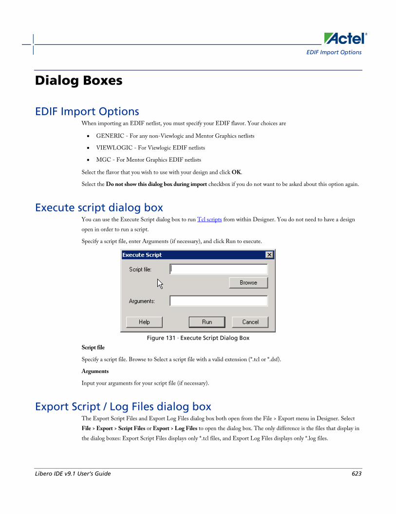
EDIF Import Options
Libero IDE v9.1 User’s Guide 623
Dialog Boxes
EDIF Import Options When importing an EDIF netlist, you must specify your EDIF flavor. Your choices are
• GENERIC - For any non-Viewlogic and Mentor Graphics netlists
• VIEWLOGIC - For Viewlogic EDIF netlists
• MGC - For Mentor Graphics EDIF netlists
Select the flavor that you wish to use with your design and click OK.
Select the Do not show this dialog box during import checkbox if you do not want to be asked about this option again.
Execute script dialog box You can use the Execute Script dialog box to run Tcl scripts from within Designer. You do not need to have a design open in order to run a script.
Specify a script file, enter Arguments (if necessary), and click Run to execute.
Figure 131 · Execute Script Dialog Box
Script file
Specify a script file. Browse to Select a script file with a valid extension (*.tcl or *.dsf).
Arguments
Input your arguments for your script file (if necessary).
Export Script / Log Files dialog box The Export Script Files and Export Log Files dialog box both open from the File > Export menu in Designer. Select File > Export > Script Files or Export > Log Files to open the dialog box. The only difference is the files that display in the dialog boxes: Export Script Files displays only *.tcl files, and Export Log Files displays only *.log files.

Dialog Boxes
624 Libero IDE v9.1 User’s Guide
Figure 132 · Export Script / Log Files Dialog Box
Save in
Specifies the location of the file you are about to save.
File name
Specifies the filename of your new Tcl script or log file.
Save as type
Depending on your dialog box, saves the file as a LOG (*.log) file or a TCL (*.tcl) file
Generate a programming file dialog box (Designer) The Generate a programming file dialog box that appears depends on which device you are using.
If you are using a family that uses FlashPoint, the FlashPoint dialog box opens.
If you are using a family that uses a bitstream or STAPL file for programming, the dialog box is slightly different.
If you are generating a fuse file for programming an antifuse device (such as SX-A), the Generate a Fuse file dialog box appears.

Migration Options dialog box - ProASIC3/E to IGLOO/e and ProASIC3/E to ProASIC3L
Libero IDE v9.1 User’s Guide 625
Migration Options dialog box - ProASIC3/E to IGLOO/e and ProASIC3/E to ProASIC3L
The ProASIC3/E to IGLOO and ProASIC3/E to ProASIC3L Migration Options dialog box appears only when you change your device family from ProASIC3/E to IGLOO or ProASIC3L.
It enables you to set IGLOO and ProASIC3L die voltage options before you re-compile your design.
Figure 133 · Figure 134 · ProASIC3/E to IGLOO/e Migration Options Dialog Box
IGLOO/e die voltage - (option available only when migrating from ProASIC3/E to IGLOO/e) Set your die voltage to 1.5V or 1.2V.
Click Cancel to cancel out of the setup without making any changes.
Open dialog box (Designer) Use the Open dialog box to open files in Designer. This dialog box appears when you select File > Open in Designer.

Dialog Boxes
626 Libero IDE v9.1 User’s Guide
Figure 135 · Open Dialog Box (Designer)
Look in
Specifies from which directory you want to open the file. Navigate to a different directory if necessary.
File name
Specify a filename; type in part of a filename to filter files by that name.
Files of type
Select a file type from the drop-down menu to display only files of that type.
SDC Export Options dialog box To access this dialog, from the File menu, choose Export>Constraint Files, select SDC Files (*.sdc) as the type, and then click Save.
Use this dialog box to specify the scenario, the SDC variant and the pin separator in your exported SDC file. Options include:
• Export this scenario: Select which scenario the files will be imported to.
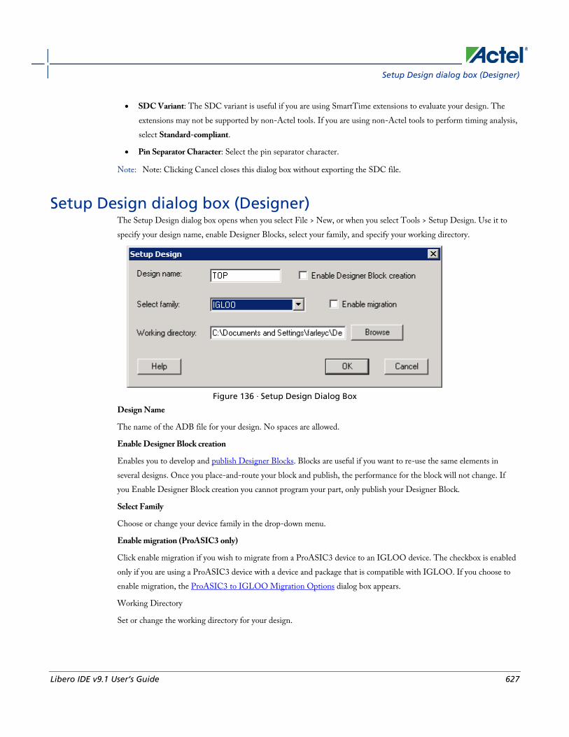
Setup Design dialog box (Designer)
Libero IDE v9.1 User’s Guide 627
• SDC Variant: The SDC variant is useful if you are using SmartTime extensions to evaluate your design. The extensions may not be supported by non-Actel tools. If you are using non-Actel tools to perform timing analysis, select Standard-compliant.
• Pin Separator Character: Select the pin separator character.
Note: Note: Clicking Cancel closes this dialog box without exporting the SDC file.
Setup Design dialog box (Designer) The Setup Design dialog box opens when you select File > New, or when you select Tools > Setup Design. Use it to specify your design name, enable Designer Blocks, select your family, and specify your working directory.
Figure 136 · Setup Design Dialog Box
Design Name
The name of the ADB file for your design. No spaces are allowed.
Enable Designer Block creation
Enables you to develop and publish Designer Blocks. Blocks are useful if you want to re-use the same elements in several designs. Once you place-and-route your block and publish, the performance for the block will not change. If you Enable Designer Block creation you cannot program your part, only publish your Designer Block.
Select Family
Choose or change your device family in the drop-down menu.
Enable migration (ProASIC3 only)
Click enable migration if you wish to migrate from a ProASIC3 device to an IGLOO device. The checkbox is enabled only if you are using a ProASIC3 device with a device and package that is compatible with IGLOO. If you choose to enable migration, the ProASIC3 to IGLOO Migration Options dialog box appears.
Working Directory
Set or change the working directory for your design.

Dialog Boxes
628 Libero IDE v9.1 User’s Guide
Variables Console dialog box The Variables Console provides direct access to internal settings of the Designer software. Although the Variables Console enables you to inspect and modify the internal settings, normally you do not need to do so, and making incorrect changes can result in adverse software behavior. Under certain circumstances, Actel Technical Support may walk you through instructions on how to view or change a setting using the Variables Console in Designer.
Figure 137 · Variables Console Dialog Box
Designer File Menu
New
CTRL + N
Opens the Setup Design dialog box and prompts you to enter a design name, select a family, and specify a working directory
Open
CTRL + O
Opens the Designer Open file dialog box; enables you to select a file to open
Close Closes the current file
Save
CTRL + S
Saves changes to the current file
Save As Enables you to save the file as a different type (such as TXT)
Execute Script CTRL Opens the Execute Script dialog box; use it to enter

Designer View menu
Libero IDE v9.1 User’s Guide 629
+ U arguments and run Tcl scripts.
Import Source Files
Opens the Import Source Files dialog box; enables you to select and import source files (such as netlist and constraint files). Source files are audited to coordinate your design changes.
Import Auxiliary Files
Opens the Import Auxiliary Files dialog box. Aux files are not audited; if you make changes to an auxiliary file after you import it, Designer does not ask you to re-import the file.
Audit Settings Opens the Audit Settings dialog box; enables you to view all the source files, change their location, and copy them to your local directory.
Export Lists all the file types you can export in Designer.
Preferences Opens the Designer Preferences dialog box
List of recent designs
Select a design from the list to open it.
Exit Exits Designer
Designer View menu The View menu enables you to select which of the Designer elements you wish to display. You can choose to display (or hide) the standard tools (buttons for New, Open, Save, and About), the Design Tools (Compile, Layout, Back-annotate, Generate Programming File, and other tools), the Status Bar, and the Log Window.
Designer Tools menu The list of Tools varies according to your device family. Some tools, such as SmartTime and ChipPlanner, are not supported by all families. For a complete list of tools supported by each family, see the help for that tool.
Command Icon Function
Setup Design Opens the Setup Design dialog box. Enter a design name, select a family, and specify a working directory for your design. You must save your design to commit your changes.
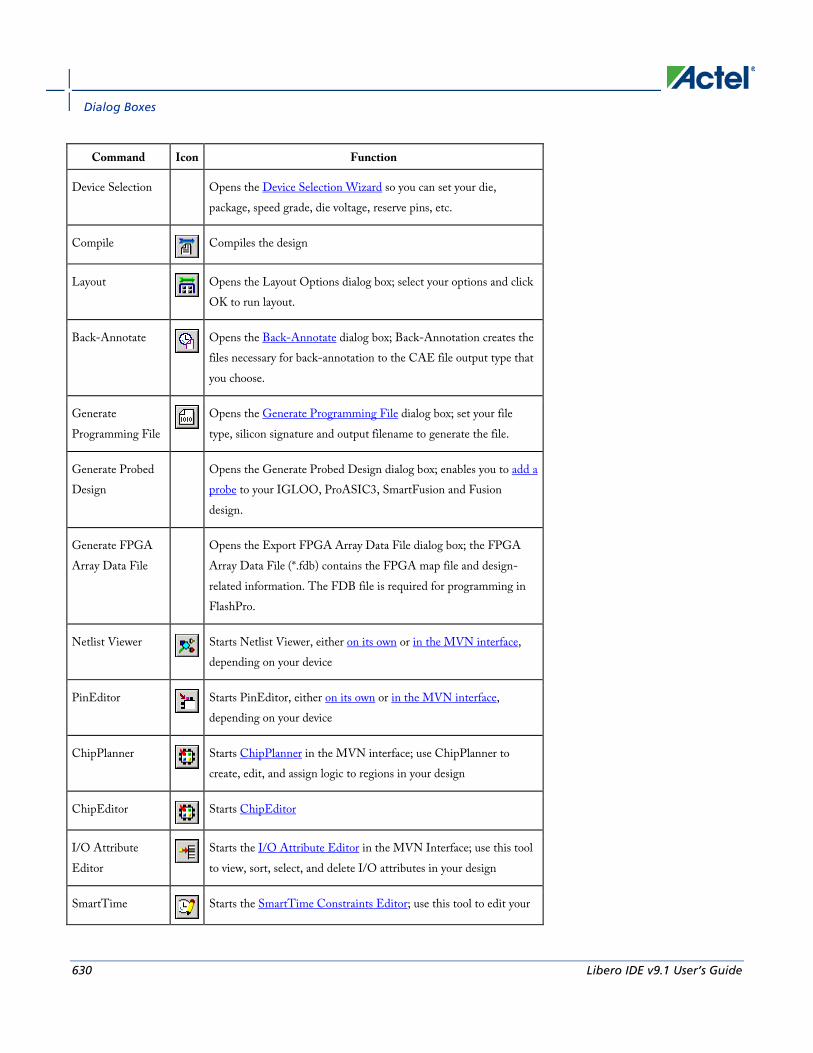
Dialog Boxes
630 Libero IDE v9.1 User’s Guide
Command Icon Function
Device Selection Opens the Device Selection Wizard so you can set your die, package, speed grade, die voltage, reserve pins, etc.
Compile
Compiles the design
Layout
Opens the Layout Options dialog box; select your options and click OK to run layout.
Back-Annotate
Opens the Back-Annotate dialog box; Back-Annotation creates the files necessary for back-annotation to the CAE file output type that you choose.
Generate Programming File
Opens the Generate Programming File dialog box; set your file type, silicon signature and output filename to generate the file.
Generate Probed Design
Opens the Generate Probed Design dialog box; enables you to add a probe to your IGLOO, ProASIC3, SmartFusion and Fusion design.
Generate FPGA Array Data File
Opens the Export FPGA Array Data File dialog box; the FPGA Array Data File (*.fdb) contains the FPGA map file and design-related information. The FDB file is required for programming in FlashPro.
Netlist Viewer
Starts Netlist Viewer, either on its own or in the MVN interface, depending on your device
PinEditor
Starts PinEditor, either on its own or in the MVN interface, depending on your device
ChipPlanner
Starts ChipPlanner in the MVN interface; use ChipPlanner to create, edit, and assign logic to regions in your design
ChipEditor
Starts ChipEditor
I/O Attribute Editor
Starts the I/O Attribute Editor in the MVN Interface; use this tool to view, sort, select, and delete I/O attributes in your design
SmartTime
Starts the SmartTime Constraints Editor; use this tool to edit your
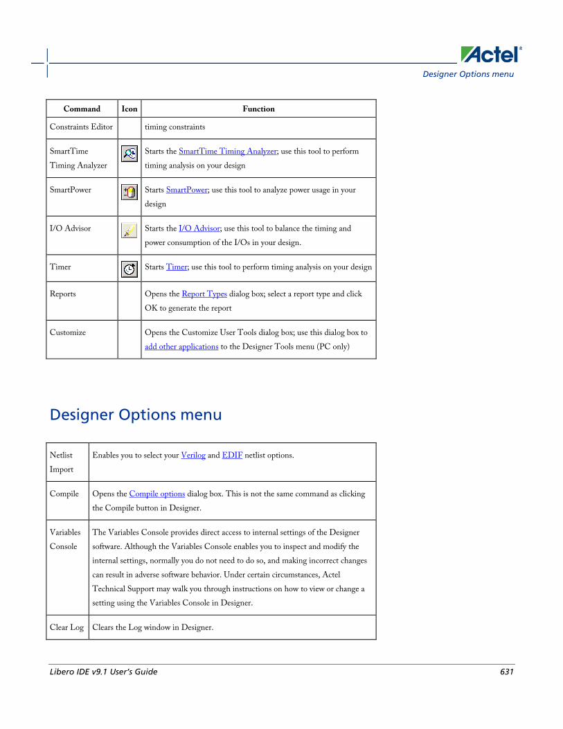
Designer Options menu
Libero IDE v9.1 User’s Guide 631
Command Icon Function
Constraints Editor timing constraints
SmartTime Timing Analyzer
Starts the SmartTime Timing Analyzer; use this tool to perform timing analysis on your design
SmartPower
Starts SmartPower; use this tool to analyze power usage in your design
I/O Advisor
Starts the I/O Advisor; use this tool to balance the timing and power consumption of the I/Os in your design.
Timer
Starts Timer; use this tool to perform timing analysis on your design
Reports Opens the Report Types dialog box; select a report type and click OK to generate the report
Customize Opens the Customize User Tools dialog box; use this dialog box to add other applications to the Designer Tools menu (PC only)
Designer Options menu
Netlist Import
Enables you to select your Verilog and EDIF netlist options.
Compile Opens the Compile options dialog box. This is not the same command as clicking the Compile button in Designer.
Variables Console
The Variables Console provides direct access to internal settings of the Designer software. Although the Variables Console enables you to inspect and modify the internal settings, normally you do not need to do so, and making incorrect changes can result in adverse software behavior. Under certain circumstances, Actel Technical Support may walk you through instructions on how to view or change a setting using the Variables Console in Designer.
Clear Log Clears the Log window in Designer.

Dialog Boxes
632 Libero IDE v9.1 User’s Guide
Designer Help menu The Help menu enables you to access the Designer online help, reference manuals, check for updates, and view your license and version information.
Command Function
Help Topics Opens the Libero IDE online help
Reference Manuals Opens the list of manuals (PDF files) available for Designer, including links to library guides, and PDF versions of the online help.
Actel Technical Support
Displays the Actel customer support web page in your default browser
Actel Web Site Displays the main Actel page in your default browser
Check for Software Updates
Checks for updates to the Designer software
License Details Displays detailed license information for your version of Designer.
About Actel Designer Software
Displays version and release numbers for your Designer software

Libero IDE v9.1 User’s Guide 633
Product Support
Actel backs its products with various support services including Customer Service, a Customer Technical Support Center, a web site, an FTP site, electronic mail, and worldwide sales offices. This appendix contains information about contacting Actel and using these support services.
Customer Service Contact Customer Service for non-technical product support, such as product pricing, product upgrades, update information, order status, and authorization. From Northeast and North Central U.S.A., call 650.318.4480 From Southeast and Southwest U.S.A., call 650. 318.4480 From South Central U.S.A., call 650.318.4434 From Northwest U.S.A., call 650.318.4434 From Canada, call 650.318.4480 From Europe, call 650.318.4252 or +44 (0) 1276 401 500 From Japan, call 650.318.4743 From the rest of the world, call 650.318.4743 Fax, from anywhere in the world 650. 318.8044
Actel Customer Technical Support Center Actel staffs its Customer Technical Support Center with highly skilled engineers who can help answer your hardware, software, and design questions. The Customer Technical Support Center spends a great deal of time creating application notes and answers to FAQs. So, before you contact us, please visit our online resources. It is very likely we have already answered your questions.
Actel Technical Support Visit the Actel Customer Support website (http://www.actel.com/support/search/default.aspx) for more information and support. Many answers available on the searchable web resource include diagrams, illustrations, and links to other resources on the Actel web site.
Website You can browse a variety of technical and non-technical information on Actel’s home page, at http://www.actel.com/.
Contacting the Customer Technical Support Center Highly skilled engineers staff the Technical Support Center from 7:00 A.M. to 6:00 P.M., Pacific Time, Monday through Friday. Several ways of contacting the Center follow:
Email You can communicate your technical questions to our email address and receive answers back by email, fax, or phone. Also, if you have design problems, you can email your design files to receive assistance. We constantly monitor the email account throughout the day. When sending your request to us, please be sure to include your full name, company name, and your contact information for efficient processing of your request.

Product Support
634 Libero IDE v9.1 User’s Guide
The technical support email address is [email protected].
Phone Our Technical Support Center answers all calls. The center retrieves information, such as your name, company name, phone number and your question, and then issues a case number. The Center then forwards the information to a queue where the first available application engineer receives the data and returns your call. The phone hours are from 7:00 A.M. to 6:00 P.M., Pacific Time, Monday through Friday. The Technical Support numbers are:
650.318.4460 800.262.1060 Customers needing assistance outside the US time zones can either contact technical support via email ([email protected]) or contact a local sales office. Sales office listings can be found at www.actel.com/company/contact/default.aspx.


Actel Corporation • 2061 Stierlin Court • Mountain View, CA 94043 • USA Phone 650.318.4200 • Fax 650.318.4600 • Customer Service: 650.318.1010 • Customer Applications Center: 800.262.1060 Actel Europe Ltd. • River Court, Meadows Business Park • Station Approach, Blackwater • Camberley Surrey GU17 9AB • United Kingdom Phone +44 (0) 1276 609 300 • Fax +44 (0) 1276 607 540 Actel Japan • EXOS Ebisu Building 4F • 1-24-14 Ebisu Shibuya-ku • Tokyo 150 • Japan Phone +81.03.3445.7671 • Fax +81.03.3445.7668 • http://jp.actel.com Actel Hong Kong • Room 2107, China Resources Building • 26 Harbour Road • Wanchai • Hong Kong Phone +852 2185 6460 • Fax +852 2185 6488 • www.actel.com.cn
5-02-9124-26/11.10
Actel is the leader in low-power and mixed-signal FPGAs and offers the most comprehensive portfolio of system and power management solutions. Power Matters. Learn more at http://www.actel.com .
Related Documents