Group 12 - CREOL Senior Design I 1 Initial Project Document Li-Fi ( Light Fidelity) An alternative to the wireless transmission with RF spectrums through visible light communication. University of Central Florida Department of Electrical Engineering and Computer Science EEL 4914 Dr. Lei Wei, Dr. David Hagen Senior Design I Group 12 - CREOL ● Zhitao Chen Electrical Engineering ● Garrett Bennett Photonic Science and Engineering ● Benjamin Stuart Photonic Science and Engineering ● George Salinas Computer Engineering Project Narrative Currently there are more than 15 billion Wi-Fi enabled devices in the world, and it’s not just cell phones and computers. The fact is, most household appliances are equipped with Wi-Fi capabilities, and the spectrum

Welcome message from author
This document is posted to help you gain knowledge. Please leave a comment to let me know what you think about it! Share it to your friends and learn new things together.
Transcript

Group 12 - CREOL Senior Design I
1
Initial Project Document
Li-Fi ( Light Fidelity) An alternative to the wireless transmission with RF spectrums through visible light
communication.
University of Central Florida
Department of Electrical Engineering and Computer Science
EEL 4914
Dr. Lei Wei, Dr. David Hagen
Senior Design I
Group 12 - CREOL
● Zhitao Chen Electrical Engineering
● Garrett Bennett Photonic Science and Engineering
● Benjamin Stuart Photonic Science and Engineering
● George Salinas Computer Engineering
Project Narrative
Currently there are more than 15 billion Wi-Fi enabled devices in the world, and it’s not just cell phones and
computers. The fact is, most household appliances are equipped with Wi-Fi capabilities, and the spectrum
Group 12 - CREOL Senior Design I
2
allotted for 802.11 protocol (local wireless networks) is becoming increasingly saturated and scarce. If we
look at long haul communication systems, we see that in the past decades the industry has migrated from
traditional copper cables to fiber optic systems. Optical systems provide greatly increased bandwidths and
bitrates, and here we propose the same concept.
Li-Fi technology is very similar to Wi-Fi technology in the sense that it is a local wireless network, however
the signal is visible light instead of in the radio frequencies. Since visible light frequency is much higher on
the EM spectrum Li-Fi systems provide bandwidth many times greater than Wi-Fi. In addition Li-Fi is
considerably more energy efficient, since the transmitter in the system is an LED instead of a conventional
radio transmitter. Li-Fi is also a secure means of data transfer, the modulating light itself represents the
data stream, and since light does not penetrate walls there is no way to remotely intercept the data. Our
system will also be full duplex unlike VLC systems that are only one-way communications. Li-Fi systems
are non-hazardous to other electrical systems in terms of interference, making them more versatile in
settings like a airplanes or settings with high sensitivity to electromagnetic radiation.
For this project we propose using two sets of receivers and transmitters, the set of transmitters will use a
broadband LED and the other using an IR LED. The receivers will have the ability to not restrict the flow of
the data, or have similar response times to the LED itself. In a practical environment, the ceiling lights
would serve as our downlink, in this case we will use a regular “off the shelf” LED. Since Li-Fi is a
complementary technology, a system would make use of existing data lines, for instance our system will
use power over ethernet (POE) to power the LED, reducing energy consumption and excessive electrical
wires. The LED would receive the incoming data from the Ethernet port and be directly modulated as a
consequence. On the other end a photodetector such as a solar cell will collect the light, and provide a
modulated voltage that will be amplified and interfaced with a USB connection, making it a universal system.
Light emitting diode (LED) light bulbs not only can provide energy efficiency in illuminating houses, and
stores, but have the ability to modulate with various schemes such as pulse width modulation (PWM) and
or pulse position modulation (PPM). Furthermore techniques such as orthogonal frequency division
multiplexing can be implemented to allow for access to multiple users from one transmitting network. This
project will focus on implementing a connection from an ethernet port into a intensity modulation format for
the LED.
As the internet of things (IoT) continues to evolve, the various devices in the home will require connectivity.
This rate of increase is going to impact the ability of our wireless transmitting devices to carry that bandwidth
which is where LiFi can be application specific and not be for consumer use. Furthermore the IoT has
applications such as theme parks where at each station or ride can have independent data be transmitted
to a multimedia device for the consumer such as in augmented reality. The LiFi systems overall is cost
effective because of power consumption and it should be comparable to a WiFi module, and can be
investigated to implement with PoE and create new applications industry can take advantage of.
Table 1: Requirements Specifications
Requirement ID Requirement Specification

Group 12 - CREOL Senior Design I
3
1.0 The system shall have the ability to transmit information through LED light.
1.1 The system shall have the ability to transmit the information with a comparable or faster bandwidth compared to Wi-Fi.
1.2 The system should be able to convert ethernet 10/100 Base-T input into a modulation scheme for an LED.
1.3 Have the ability to be used in low illumination settings undetectable to the eye.
1.4 LEDs should provide very low power consumptions, and have a very long lifetime.
1.5 The system should not create interference with sensitive electronics.
1.6 Security ability for internet protocols can be maintained.

Group 12 - CREOL Senior Design I
4
House of Quality
Figure 1: The house of quality of the system specifications.
The house of quality represents a visual overview of the system requirements. In order to obtain the
above relationships our product should be well engineered and tested.

Group 12 - CREOL Senior Design I
5
Block Diagram
Figure 2: Block diagram for the proposed LiFi system
Project Block Diagram Status:
● The amplification and power systems block may rely on high speed high amperage linear
amplifiers and PoE. It will be at least 100 MHz and output 1A.
● The photodetectors and illumination LED has been picked in table _ below.
● Prototyping for the system will be done in stages.

Group 12 - CREOL Senior Design I
6
Data Flowchart
Figure 3: High level overview of data flow.
Group 12 - CREOL Senior Design I
7
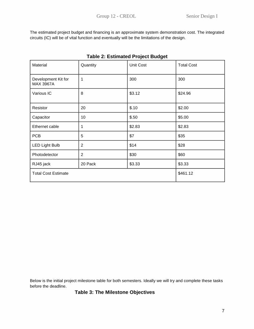
The estimated project budget and financing is an approximate system demonstration cost. The integrated
circuits (IC) will be of vital function and eventually will be the limitations of the design.
Table 2: Estimated Project Budget
Material Quantity Unit Cost Total Cost
Development Kit for MAX 3967A
1 300 300
Various IC 8 $3.12 $24.96
Resistor 20 $.10 $2.00
Capacitor 10 $.50 $5.00
Ethernet cable 1 $2.83 $2.83
PCB 5 $7 $35
LED Light Bulb 2 $14 $28
Photodetector 2 $30 $60
RJ45 jack 20 Pack $3.33 $3.33
Total Cost Estimate $461.12
Below is the initial project milestone table for both semesters. Ideally we will try and complete these tasks
before the deadline.
Table 3: The Milestone Objectives

Group 12 - CREOL Senior Design I
8
Description Time will take it to complete Deadline
Senior design 1
Form Group 1 hour 5/18/2017
1 page project idea 1 hour 5/19/2017
10 pages report 6-10 hours 6/2/2017
Divide and conquer 30 minutes 6/6/2017
Component Testing Start N/A 6/6/2017
Meeting with Dr. Hagen 30 minutes Random
Breadboard Testing N/A 7/3/2017
60 Page report 10-20 hours 7/7/2017
Design PCB 10-20 hours 7/14/2017
100 pages report 10-20 hours 7/21/2017
Final document 8-12 hours 8/1/2017
Order PCB 3 Weeks 8/1/2017
Testing N/A Break
Senior Design 2
Finalize Design 1 days 8/25/2017
Send out second PCB 1 week 9/8/2017
Prototype 1 week 9/17/2017
Testing and redesign 2 weeks 10/1/2017
Finalize prototype 2weeks 10/15/2017
Peer presentation 30 minutes 11/1/2017
Final report 2 weeks 11/20/2017
Final Presentation/ 30 minutes 12/1/2017
Below is the circuit schematic of a 100Base-T VLC Transceiver found in “Foundations of
Visible Light Communication Circuits” by Lih Chieh Png and Kiat Seng Yeo from Singapore University. Png
and Yeo have made designs for LED’s which do not have enough luminous flux to light up a room. The
team has deduced that the output current from the MAX 3967 will not be enough to drive the illumination

Group 12 - CREOL Senior Design I
9
LED and linear amplifiers with >100 MHz and can provide 700 mA to 1200 mA need to be used. Furthermore
the OPA 658 is obsolete and the OPA694ID will be able to replace it.
Prototype Design Premise
Figure 4: Ethernet Connected 100Base-T VLC Transceiver device
The transceiver model will involve the ability to convert the MLT-3 code from a 100Base-T signal into a
suitable regime for an LED. The MLT-3 signal is inherently not applicable for LED illumination because it is
a -1 V, 0 V, 1 V signal at around 300 ns. Therefore we need to convert this into a suitable signal for LED
modulation. The MLT-3 needs to be converted into a 100base-FX signal which is suitable for LED
modulation. The idea is to build a robust system which can convert the Ethernet signals MLT-3 (analog) to
digital signals as in binary or NRZI before feeding them into the LED. NRZI signals are also referred to as
PECL (positive emitter-coupled logic). At the receiver the conversion will be binary back to MLT-3.
THE BACK UP PLAN. Which we do not want to do.

Group 12 - CREOL Senior Design I
10
Portable wireless spectrometer for non destructive testing of produce.
DOI: 10.1038/srep32504
The ability to obtain the optical spectrum of organic tissue can reveal the spectral signature or fingerprint
of that organism. The measurement can readily be transformed from the quantitative spectral graph into a
qualitative declaration via correlative methods such as cross correlation and auto correlations of the fourier
transforms compared to a database. Spectrometers are usually limited for commercial settings because of
their required computing device and in ability to be robust. The proposed housing will be robust and have
tolerance to high impact to maintain the position of the sensitive optics. The product will be a standalone
platform able to communicate with a wireless phone via bluetooth. The bluetooth link in the phone will be
able to exchange the information of the calculated quantitative data and display it for the user. In the
electrical side It will have charging capabilities and be able to drive an ultraviolet LED at a constant current.
The group will focus on making this prototype into a manufacturable product because of the newly designed
PCB. The hamamatsu mini-spectrometer chip has the ability to have a spectral response between 340 nm
to 850 nm with a 15 nm maximum spectral resolution. The allows for the device to obtain a high quality
spectrum. The housing design can also be changed because of the new compactness of the PCB.
Figure 5. (a) Schematic of the constituent components. (b) Close up of the sensor nozzle depicting the
light coupling into the spectrometer and LED illumination. (c) Model of the assembled housing from the
previous author. (d) Photograph of a working prototype.
The following is a preliminary price point for development. Manufacturing should be considerably
less.

Group 12 - CREOL Senior Design I
11
Related Documents