LI-FI BASED INTELLIGENT VOICE COMMUNICATION AND DEVICE SWITCHING 1 Mrs. Harsha Karamchandani, 2 Mr. Dan Singh, 3 Mr. Sumit Kumar Ishrawal, 4 Mr. Sunit Kumar Ishrawal, 5 Mr. Utpal Karan Department of ECE, HKBK College of Engineering, Nagawara, Bangalore – 560045, Karnataka, India Abstract-Wi-Fi technology becomes more popular today. Every public spots and private offices have wifi because of this wireless spectrum is blocked very frequently. Due to maximum utility RF interferences are getting more common to overcome this problem light fidelity (Li-Fi) technology was introduced in the year 2011. Li-Fi is similar to other wireless communication which uses the communication medium as light. Visible light is use to transfer data between the system instead of radio signals. Li-Fi uses LED light source to transmit the data wirelessly this method is widely called as VLC (visible light communication). A stream of data transmitted in the way of pulses of light that cannot be detected by the naked eye. This paper speaks about the new vlc technology over the existing wifi technology and the challenges of new Li-Fi technology. I. Introduction Li-Fi comprises a wide range of frequencies and wavelengths, from the infrared through visible and down to the ultraviolet spectrum. It includes sub-gigabit and gigabit-class communication speeds for short, medium and long ranges, and unidirectional and bidirectional dat transfer using line-of-sight or diffuse links, reflections and much more. It is not limited to LED or laser technologies or to a particular receiving technique. Li-Fi is a framework for all of these providing new capabilities to current and future services, applications and end users. This brilliant idea was first showcased by Harald Haas from University of Edinburgh, UK, in his TED Global talk on VLC. He explained, very simple, if the LED is on, you transmit digital 1;if it’s off you transmit a 0. In simple terms, Li-Fi can be thought of as a light-based Wi-Fi. That is, it uses light instead of radio waves to transmit information. And instead of Wi-Fi modems, Li-Fi would use transceiver-fitted LED lamps that can light a room as well as transmit and receive information. Since simple light bulbs are used, there can technically be any number of access points. It is possible to encode data in the light by varying the rate at which the LEDs flicker on and off to give different strings of 1s and 0s. The LED intensity is modulated so rapidly that human eyes cannot notice, so the output appears constant. II. Principle of Li-Fi technology The important segment of the Li-Fi technology is the high power Led lights, led can be turned on & off quickly because the reaction time of the led is lesser than 1 microsecond which cannot be detected by the human eye this will appear to be continues beam of light. This change from on state to off state in high frequencies enables the data transmission. On states ‘1’ and off states ‘0’the data can be encoded and modulation techniques can be done faster than the human eye can detect it. A photo detector can be used to receive the transmitted data from the light source and generates the original data. This method continuously receives the pulses of light and decode into the stream of data is referred as VLC (visible light communication). III. Working and Construction of Li-Fi Li-Fi is typically implemented using white LED light bulbs at the downlink transmitter. These devices are normally used for illumination only by applying a constant current. However, by fast and subtle variations of the current, the optical output can be made to vary at extremely high speeds. This very property of optical current is used in Li-Fi setup. The operational procedure is very simple-, if the LED is on, you transmit a digital 1, if it’s off you 1

Welcome message from author
This document is posted to help you gain knowledge. Please leave a comment to let me know what you think about it! Share it to your friends and learn new things together.
Transcript

LI-FI BASED INTELLIGENT VOICE COMMUNICATION AND
DEVICE SWITCHING 1Mrs. Harsha Karamchandani, 2Mr. Dan Singh, 3Mr. Sumit Kumar Ishrawal, 4Mr. Sunit Kumar
Ishrawal, 5Mr. Utpal Karan
Department of ECE, HKBK College of Engineering, Nagawara, Bangalore – 560045, Karnataka, India
Abstract-Wi-Fi technology becomes more
popular today. Every public spots and
private offices have wifi because of this
wireless spectrum is blocked very
frequently. Due to maximum utility RF
interferences are getting more common to
overcome this problem light fidelity (Li-Fi)
technology was introduced in the year 2011.
Li-Fi is similar to other wireless
communication which uses the
communication medium as light. Visible
light is use to transfer data between the
system instead of radio signals. Li-Fi uses
LED light source to transmit the data
wirelessly this method is widely called as
VLC (visible light communication). A
stream of data transmitted in the way of
pulses of light that cannot be detected by the
naked eye. This paper speaks about the new
vlc technology over the existing wifi
technology and the challenges of new Li-Fi
technology.
I. Introduction
Li-Fi comprises a wide range of frequencies
and wavelengths, from the infrared through
visible and down to the ultraviolet spectrum.
It includes sub-gigabit and gigabit-class
communication speeds for short, medium
and long ranges, and unidirectional and
bidirectional dat transfer using line-of-sight
or diffuse links, reflections and much more.
It is not limited to LED or laser technologies
or to a particular receiving technique. Li-Fi
is a framework for all of these providing
new capabilities to current and future
services, applications and end users. This
brilliant idea was first showcased by Harald
Haas from University of Edinburgh, UK, in
his TED Global talk on VLC. He explained,
very simple, if the LED is on, you transmit
digital 1;if it’s off you transmit a 0. In
simple terms, Li-Fi can be thought of as a
light-based Wi-Fi. That is, it uses light
instead of radio waves to transmit
information. And instead of Wi-Fi modems,
Li-Fi would use transceiver-fitted LED
lamps that can light a room as well as
transmit and receive information. Since
simple light bulbs are used, there can
technically be any number of access points.
It is possible to encode data in the light by
varying the rate at which the LEDs flicker
on and off to give different strings of 1s and
0s. The LED intensity is modulated so
rapidly that human eyes cannot notice, so
the output appears constant.
II. Principle of Li-Fi technology
The important segment of the Li-Fi
technology is the high power Led lights, led
can be turned on & off quickly because the
reaction time of the led is lesser than 1
microsecond which cannot be detected by
the human eye this will appear to be
continues beam of light. This change from
on state to off state in high frequencies
enables the data transmission. On states ‘1’
and off states ‘0’the data can be encoded
and modulation techniques can be done
faster than the human eye can detect it. A
photo detector can be used to receive the
transmitted data from the light source and
generates the original data. This method
continuously receives the pulses of light and
decode into the stream of data is referred as
VLC (visible light communication).
III. Working and Construction of Li-Fi
Li-Fi is typically implemented using white
LED light bulbs at the downlink transmitter.
These devices are normally used for
illumination only by applying a constant
current. However, by fast and subtle
variations of the current, the optical output
can be made to vary at extremely high
speeds. This very property of optical current
is used in Li-Fi setup. The operational
procedure is very simple-, if the LED is on,
you transmit a digital 1, if it’s off you
1
Techno Buzz
Dept. of Electronics and Communication Engineering, HKBKCE

transmit a 0. The LEDs can be switched on
and off very quickly, which gives nice
opportunities for transmitting data.
Li-Fi, or "light fidelity", is a technology,
that can be a complement of RF
communication (Wi-Fi or Cellular network),
or a replacement in contexts of data
broadcasting. Li-Fi, like Wi-Fi, is the high
speed, bidirectional and fully networked
subset of visible light communications
(VLC). It is wireless and uses visible light
communication (instead of radio frequency
waves), which carries much more
information, and has been proposed as a
solution to the RF-bandwidth limitations.
Fig.1 Block diagram of Transmitter Section
LIGHT TRANSMITTER: As shown in Fig.1 simple module of Li-Fi Tx
which have two stages pre-amplifier and
power amplifier .At the pre- amplifier circuit
in U1 picks the transducer output ,which
catches the very low pitch sound waves .In
pre-amplifier amplifies voltage sufficiently
The condenser microphone which is biased
through R1 changes its internal-resistance with
respect to the picked sound waves. This
varying signal drives the U1 ic LM 741
through coupling capacitor C1. Hence the
corresponding amplified output signals are
observed at terminal 6 of IC U1& Through P1
we are controlling the gain . The input signals
from condenser microphone and output signals
at 6 terminal are coupled by capacitors C2 to
power amplifier input terminal 3 of IC U2 . In
power amplifier stage. Amplifies both current
and voltage sufficiently then transmitted
through light Tx.
Fig.2 Block diagram of Receiver Section
LIGHT RECEIVER: As shown in Fig.2 simple module of Li-Fi Rx
which have two stages pre-amplifier and
power amplifier .At the pre- amplifier stage
U1 picks the transmitted signal through LDR
RX , which catches the very low pitch sound
waves .In pre-amplifier amplifies the voltage
sufficiently The light Rx Transistor (LDR )
which is biased through R7 & voltage divider
circuit is formed using R1 & R8 resistors. The
varying signal drives the U1 IC LM 358
through coupling capacitor C2. Hence the
corresponding amplified output signals are
observed at terminal 7 of IC U1. In power
amplifier stage.
2
Techno Buzz
Dept. of Electronics and Communication Engineering, HKBKCE
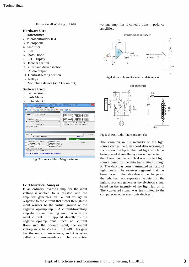
Fig.3 Overall Working of Li-Fi
Hardware Used:
1. Transformer 2. Microcontroller 8051
3. Microphone
4. Amplifier
5. LED
6. Photo Diode
7. LCD Display
8. Decoder section
9. Buffer and driver section
10. Audio output
11. Contrast setting section
12. Relays
13. Switching device (ac 230v output)
Software Used:
1. Kiel version3
2. Flash Magic
3. Embedded C
Fig. 3 Shows a Flash Magic window
IV. Theoretical Analysis
In an ordinary inverting amplifier the input
voltage is applied to a resistor, and the
amplifier generates an output voltage in
response to the current that flows through the
input resistor to the virtual ground at the
negative op-amp input. A current-to-voltage
amplifier is an inverting amplifier with the
input current I in applied directly to the
negative op-amp input. Since no current
flows into the op-amp input, the output
voltage must be Vout = Itin X –Rf. This gain
has the units of impedance, and it is often
called a trans-impedance. The current-to
voltage amplifier is called a trans-impedance
amplifier.
Fig.4 shows photo diode & led driving ckt
Fig.5 shows Audio Transmission ckt
The variation in the intensity of the light
source carries the high speed data working of
Li-Fi shown in fig.4. The Led light which has
been placed above the system is connected to
the driver module which drives the led light
source based on the data transmitted through
it. The data has been transmitted in form of
light beam. The receiver segment that has
been placed in the table detects the changes in
the light beam and separates the data from the
light source and generates the electrical signal
based on the intensity of the light fall on it.
The converted signal was transmitted to the
computer or other electronic devices.
3
Techno Buzz
Dept. of Electronics and Communication Engineering, HKBKCE

Fig.6 shows lcd interfacing with 8051
A microcontroller is often small and low
cost. The components are chosen to minimize
size and to be as inexpensive as possible. A
microcontroller is often, but not always,
ruggedized in some way. The microcontroller
controlling a car's engine, for example, has to
work in temperature extremes that a normal
computer generally cannot handle. A car's
microcontroller in Kashmir regions has to
work fine in -30 degree F (-34ᵒC) weather,
while the same microcontroller in Gujarat
region might be operating at 120 degrees F
(49ᵒC). When you add the heat naturally
generated by the engine, the temperature can
go as high as 150 or 180 degrees F (65-80ᵒC)
in the engine compartment. On the other
hand, a microcontroller embedded inside a
VCR hasn't been ruggedized at all.
V. Advantages
a) Green information technology: - Green
information technology means that unlike
radio waves and other communication waves
affects on the birds, human bodies etc. Li-Fi
never gives such side effects on any living
thing.
b) Free From Frequency Bandwidth Problem:-
Li-fi is an communication media in the form of
light ,so no matter about the frequency
bandwidth problem . It does not require the
any bandwidth spectrum i.e. we don’t need to
pay any amount for communication and
license
e) Lightings Points Used as Hotspot:- Any
lightings device is performed as a hotspot it
means that the light device like car lights,
ceiling lights, street lamps etc.
VI. Applications:
The remote control devices under the ocean:
radio wave doesn’t work there.
Petrochemical plants: radio wave data
transmission is not secured there.
Street lights, traffic signals: for traffic
update.
4
Techno Buzz
Dept. of Electronics and Communication Engineering, HKBKCE

VII. Issues on communication:
Other than the advantages of the Li-Fi
technology it faces more challenges. Li-Fi
needs line of sight transmission limit. It
cannot penetrate any obstacles so even a
person stand between the receiver and the
light source can stop the function of Li-Fi
system which results in failure of system. An
important challenge is how to transmit the
data from reception side to transition side or
vice-versa. When the Li-Fi system is placed
outdoor then the system should face the
changes in climatic conditions and in indoor
the receiving device cannot be shifted around
the places. when we compare in the terms
of power consumption the Li-Fi requires
only the 1 watt of power supply we can
power the led all around the room. Using a
single power led bulb we can connect four
computers to the online with transfer rate of
150mb/s. The speed of the data transitions
getting higher to Gbs by several research
works. While comparing the efficiency,
speed and power consumption the Li-Fi
technology is more effective than that of Wi-
Fi that used widely now a days.
VIII. Experimental Results:
We done this experiment in lab and we
have been got the result as we expect in our
theoretical analysis. In this experiment we
done transferring of data as text and audio
signal and also controlling the switches
through light. Here we have two module
transmitter and receiver and it is unidirectional.
Fig.7 Shows Hardware module of Li-Fi
IX. Conclusion:
The possibilities are numerous and can be
explored further. If his technology can be put
into practical use, every bulb can be used
something like a Wi-Fi hotspot to transmit
wireless data and we will proceed toward the
cleaner, greener, safer and brighter future. The
concept of Li-Fi is currently attracting a great
deal of interest, not least because it may offer a
genuine and very efficient alternative to radio-
based wireless. As a growing number of
people and their many devices access wireless
internet, the airwaves are becoming
increasingly clogged, making it more and
more difficult to get a reliable, high-speed
signal. This may solve issues such as the
shortage of radio-frequency bandwidth and
also allow internet where traditional radio
based wireless isn’t allowed such as aircraft or
hospitals. One of the shortcomings however is
that it only work in direct line of sight.
References:
[1].A. Haas, L. Yin, Y. Wang and C. Chen,
"What is LiFi?," in Journal of
LightwaveTechnology,vol.34,no.6,pp.1533-
1544,March15,2016.
[2].R. Scopigno, A. Autolitano, T. Acarman, Ç
Yaman and S. Topsu, "The potential benefits
of on-board Li-Fi for the cooperation among
vehicles," 2015 17th International Conference
on Transparent Optical Networks (ICTON),
Budapest, 2015.
[3].H. Haas and C. Chen, "What is LiFi?,"
Optical Communication (ECOC), 2015
European Conference on, Valencia, 2015, pp.
1-3.
[4].N. A. Abdulsalam, R. A. Hajri, Z. A. Abri,
Z. A. Lawati and M. M. Bait-Suwailam,
"Design and implementation of a vehicle to
vehicle communication system using Li-Fi
technology," Information and Communication
Technology Research (ICTRC), 2015
International Conference
[5].Y. Wang, X. Wu and H. Haas, "Distributed
load balancing for Internet of Things by using
Li-Fi and RF hybrid network," Personal,
Indoor, and Mobile Radio Communications
(PIMRC), 2015 IEEE 26th Annual
International Symposium on, Hong Kong,
2015, pp. 1289-1294.
[6].H. Haas, "Visible light communication,"
5
Techno Buzz
Dept. of Electronics and Communication Engineering, HKBKCE

Optical Fiber Communications Conference
and Exhibition (OFC),2015,LossAngeles,
CA,2015,pp.1-72.
[7].T. Cogalan, H. Haas and E. Panayirci,
"Power Control-Based Multi-User Li-Fi Using
a Compound Eye Transmitter," 2015 IEEE
Global Communications Conference
(GLOBECOM), San Diego, CA, 2015, pp.1-6.
[8].Y. Wang, S. Videv and H. Haas, "Dynamic
load balancing with handover in hybrid Li-Fi
and Wi-Fi networks," 2014 IEEE 25th Annual
International Symposium on Personal, Indoor,
and Mobile Radio Communication
(PIMRC),Washington DC,2014, pp.575-579.
[9] Analytical study of Wi-Fi. Prof. Y.P.Singh
– Pradeep mIttal 2013
[10] prof. (Dr.) Y.P. Singh “A Comparative
and critical technical study of Li-Fi (A Future
communication) V/S Wi-Fi,” International
Journal of IT, Engineering and applied
sciences research (IJIEASR) ISSN: 2319-
4413, Vol 2, No. 4, April 2013
[11] ”Visible-light communication: Tripping
the light fantastic: A fast and cheap optical
version of Wi-Fi is coming”, Economist, dated
28Jan 2012
[12] “Will Li-Fi be the new Wi-Fi?, New
Scientist, by Jamie Condliffe”, dated 28 July
2011
[13].H. Park, J. Friedman, P. Gutierrez, V.
Samanta, J. Burke and M. B. Srivastava,
"Illumimote: Multimodal and High-Fidelity
Light Sensor Module for Wireless Sensor
Networks," in IEEE Sensors Journal, vol. 7,
no. 7, pp. 996-1003, July 2007.
6
Techno Buzz
Dept. of Electronics and Communication Engineering, HKBKCE
Greenhouse Monitoring Using GSM
Samuel K Justus1, Humeera Siddiqua2, Shahbaaz Khan3, Sanjay M4
[email protected], [email protected], [email protected],
Final year B.E students,Department of ECE, HKBKCollege of Engineering,
Bangalore-45, Karnataka, India
Abstract
Greenhouse monitoring is an essential one for
variableclimate changes. GSM technologies have been
rapidly developing wireless technology during recent
years. Starting from telecommunication and industrial
controls, it is now being applied in environmental
monitoring and agriculture. The old wired greenhouse
network wouldmake the measurement system expensive
and vulnerable. Moreover, the cabled measurement
points are difficult to relocate once they are installed.
This paper propose modern greenhouse measurement
system using ambient intelligence, the GSM-SMS and
sensors are used to sense climate parameters and
transmit data through wireless communication.
Keywords: Greenhouse, GSM, Wireless Sensor Network,
Environmental, Ambient Intelligence, CO2 Emission.
I. INTRODUCTION
A greenhouse is a structure with a glass or plastic
roof and frequently glass or plastic walls; the
incoming solar radiation from the sun warms plants,
soil, and other things inside the building [1].
Moreover, a greenhouse protects and a controls
environment for rising plants indoors. As we know,
most of the gar-dener uses manual system of
watering to their plant in the garden and also in the
greenhouse. This system is inefficient since when we
manually do this, the possibility to get some plant can
drown. In order to overcome this problem, automatic
greenhouse used.
The greenhouse automatic control system will fully
automate the management of a greenhouse using the
latest pervasive systems and technology. The
proposed system controls and monitors light
intensity, soil and air humidity using an Arduino and
GSM modules.
A temperature sensor, humidity sensor, soil moisture
and light sensor which are automatically controlled
are used in our project. The concern with a lot of
consumer needs and demand for the agriculture
products has stimulated awareness among the farmer
that increases their products in the market by
implementing advance technologies in this industry.
This project uses sensors and Global System for
Mobile Communication (GSM) and short message
service (SMS) to carry out data from the green house
with sensors directly alert the farmers to their mobile
phone. Therefore, this makes controlling plants easier
by directly sending alert notification messages to
farmers using GSM and SMS technology. So, this
project aims to design a smart greenhouse model
controlled automatically by a keypad. Parameters like
humidity, temperature and lightning will be
controlled by ARDUINO UNO microcontroller. Each
of these parameters is measured by a sensor that is set
at a specific range, if this sensor signals any change
in that range, the system will take the appropriate
action required, and the system sends a daily report to
the user by SMS.
When the main system identified the hazardous
condition then GSM modem activated and send the
message to another modem which is connected to
computer system and Computer system store the log
of SMS received and send and New SMS send to first
GSM and after receiving SMS, main unit can starting
the operation on greenhouse system.
Greenhouses allow you to control the temperature
and humidity, a manipulation that allows you to grow
vegetables year round. In these closed microcosm,
you can mimic the climate of any section of the
world. You also have more control of the climate,
leading to better crops.
II. BLOCK DIAGRAM
The system shown (figure 1) measures the values of
temperature, humidity, light in the greenhouse by
sensors and sends the data that was measured to the
Arduino. The Arduino processes the data and
controls the fan, dc motor, sprinkler and light to
maintain suitable conditions in the greenhouse.
7
Techno Buzz
Dept. of Electronics and Communication Engineering, HKBKCE

This project consists of Arudino, temperature sensor
(LM 35), LDR (light dependant resistor) and a
humidity sensor (DHT 11). All these sensors are
connected to controller which is main processing unit
of the system.
Figure 1 Block Diagram
The sensors sense different conditions and provide
data to controller for processing. From the data
obtained from the sensors the program controls the
actuator components heater, two cooler fans and
pump to achieve the system requirements. The
Greenhouse Automation for monitoring and
controlling of temperature, light, and humidity, etc is
shown in figure 1.
The temperature sensor which is LM35 acts as an
analog input to the controller and is connected to the
A0 pin of the Arduino, similarly the humidity sensor
also serves as the analog input to the controller and is
connected to the A1 pin of the Arduino.
The LDR and Water level sensor serves as the digital
input and is connected to the 9th and 8th pin of
Arduino. The relay switches are connected to the 4th
5th 6th and 7th pin.
III. HARDWARE REQUIREMENTS
A. ARDUINO
Arduino (figure1) is an open-source electronics
prototyping platform based on flexible, easy-to-use
hardware and software. It's intended for artists,
designers, hobbyists, and anyone interested in
creating interactive objects or environments
Arduino can sense the environment by receiving
input from a variety of sensors and can affect its
surroundings by controlling lights, motors, and other
actuators. The microcontroller on the board is
programmed using the c++language .Arduino
projects can be stand-alone or they can communicate
with software running on a computer (e.g. Flash,
Processing, MaxMSP)
Memory
The ATmega328 has 256 KB of flash memory for
storing code (of which 8 KB is used for the boot
loader), 8 KB of SRAM and 4 KB of EEPROM
(which can be read and written with the EEPROM)
and that is enough of our system.
Figure 2 Arduino
B. DC Motor
A DC motor is a mechanically commutated electric
motor powered from direct current (DC). The stator
is stationary in space by definition and therefore so is
its current. The current in the rotor is switched by the
commutator to also be stationary in space. This is
how the relative angle between the stator and rotor
magnetic flux is maintained near 90 degrees, which
generates the maximum torque.
DC motors have a rotating armature winding but non-
rotating armature magnetic field and a static field
winding or permanent magnet. Different connections
of the field and armature winding provide different
inherent speed/torque regulation characteristics. The
speed of a DC motor can be controlled by changing
the voltage applied to the armature or by changing
the field current. The introduction of variable
resistance in the armature circuit or field circuit
allowed speed control. Modern DC motors are often
controlled by power electronics systems called DC
drives.
8
Techno Buzz
Dept. of Electronics and Communication Engineering, HKBKCE

Figure 3 DC Motor
C. Temperature Sensor
An analog temperature sensor is pretty easy to
explain, it's a chip that tells you what the ambient
temperature is. These sensors use a solid-state
technique to determine the temperature. That is to
say, they don't use mercury (like old thermometers),
bimetallic strips (like in some home thermometers or
stoves), nor do they use thermistors (temperature
sensitive resistors). Instead, they use the fact as
temperature increases, the voltage across a diode
increases at a known rate. (Technically, this is
actually the voltage drop between the base and
emitter - the Vbe - of a transistor. By precisely
amplifying the voltage change, it is easy to generate
an analog signal that is directly proportional to
temperature. There have been some improvements on
the technique but, essentially that is how temperature
is measured.
Because these sensors have no moving parts, they are
precise, never wear out, don't need calibration, work
under many environmental conditions, and are
consistent between sensors and readings. Moreover
they are very inexpensive and quite easy to use.
Figure 4 LM-35
D. Float Level Sensor
In these level sensors, a float moves with the liquid
surface. The float is connected to a core via a spring.
A magnetic reed switch is mounted in the
hermetically sealed core and the core moves inside a
stem with the float movement. The stem is encircles
by powerful magnets. As the float rises or lowers
with liquid level, the reed switch gets operated due to
the magnetic field generated by the magnets.
E. Humidity sensor
Humidity is the presence of water in air. The amount
of water vapor in air can affect human comfort as
well as many manufacturing processes in industries.
The presence of water vapor also influences various
physical, chemical, and biological processes.
Humidity measurement in industries is critical
because it may affect the business cost of the product
and the health and safety of the personnel. Hence,
humidity sensing is very important, especially in the
control systems for industrial processes and human
comfort.
Figure 6 Humidity sensor
F. GSM Modem
A GSM modem is a specialized type of modem
which accepts a SIM card, and operates over a
subscription to a mobile operator, just like a mobile
phone. From the mobile operator perspective, a GSM
modem looks just like a mobile phone.
GSM Modem comes in various interfaces, such as
PCMCIA Type II, USB, and Serial. GSM Modem is
However the main difference is that GSM Modem is
wireless, while dial-up modem is wired.
9
Techno Buzz
Dept. of Electronics and Communication Engineering, HKBKCE

GSM (Global System for Mobile Communications,
originally Group Spécial Mobile), is a standard
developed by the European Telecommunications
Standards Institute (ETSI) to describe protocols for
second generation (2G) digital cellular networks used
by mobile phones. It became the de facto global
standard for mobile communications with over 80%
market share.
G. LDR
Figure 7 LDR
Light Dependent Resistors (LDR sensor) used to
measure amount of light, LDR are very useful in
light/dark sensor circuits, felled on it and send at
output analog value to be convert to digital by ADC
device. LDR device has a resistance which varies
according to the amount of light falling on its surface.
Since LDR is extremely sensitive in visible light
range.
IV. SOFTWARE REQUIREMENTS
A. Arduino IDE
The Arduino integrated development environment
(IDE) is a cross-platform app. written in Java, and is
derived from the IDE for the Processing
programming language and the Wiring projects.
• A program or code written for Arduino is
called a "sketch".
• The Arduino IDE uses the GNU toolchain
and AVR Libc to compile programs, and uses
avrdude to upload programs to the board.
V. ADVANTAGES
Greenhouses allow you to control the temperature
and humidity, a manipulation that allows you to grow
vegetables year round. In these closed microcosm,
you can mimic the climate of any section of the
world. You also have more control of the climate,
leading to better crops.
1. Saves money, time, and effort.
2. Provides a better environment to the plant to
prevent it from damage and to increase its
productivity.
3. Some plants require a longer period of
lighting than other plants; the smart greenhouse will
provide the right amount of lighting.
4. Automatically controls the amount of water
needed for each plant.
5. 10-12% increase in yield depending upon
the type of greenhouse, type of crop, environmental
control facilities
6. Reliability of crop increases in green house
cultivation
7. Expands your growing season
8. Expanding the variety among your produce
9. Minimize external threats to your crop
VI. DISADVANTAGES
The disadvantages of this project are
1. There should be good network coverage else
there will be delay in sending or receiving SMS.
2. The cost of the project is little on the
expensive side and is ideal for top level farming.
3. High upfront and operating expenses
4. Lack of pollination
5. Careful precautions must be taken to
eliminate any pest or diseases to make sure your next
crop won’t be affected
VII. RESULTS
Once the intensity of the light falling on the sensor
decreases the sensor generates a signal to the
controller which is the Arduino board and the
controller sends a signal to the GSM module which
sends a message over the network to the user, thus
enabling the user to have constant monitoring over
the system (figure 8).
10
Techno Buzz
Dept. of Electronics and Communication Engineering, HKBKCE

Figure 8
The above figure shows the screenshot of the users
mobile when the system detects low light (figure 8).
Figure 9
The above figure shows the screenshot of the users
mobile when the system detects high temperature
(figure 9).
The below figure shows the screenshot of the users
mobile when the system detects high temperature
(figure 10).
Figure 10
VIII. CONCLUSION& FUTURE SCOPE
A greenhouse environment monitoring system was
developed. The system could monitor temperature
and humidity, soil water content and CO2
concentration in greenhouse. The obtained data by
using the system will be able to provide the data
support for vegetable planting in greenhouse. The
system is reliable and runs stably. The man-machine
interface of the software system is friendly. This
system provides a good solution for centralized
management of the greenhouse group.
Automated greenhouse monitoring system consists of
various sensors, namely soil moisture, temperature
and light. These sensors sense various parameters
temperature, soil moisture and light intensity and are
then sent to the controller and control action taken by
the controller to compare with preset values. This
eliminates risk of greenhouse not being maintained at
specific environmental conditions due to human error
and labour cost can be reduced and it is eco-friendly.
Pests are eliminated by this system and also the
quality of yield can be increased.
The circuit as it is can be improved in many ways and
can be used in wide applications. It can be placed and
operated in any of the environmental conditions.
Non-conventional energy sources such as solar
panels, wind mills are used to supply power to the
automatic greenhouse equipment’s. AGMS has a
bright scope of future in agriculture field and it will
create a revolution in it.
The system could be developed by different ways
such as sending emails when an alarm happens, or
using different devices such as PLCs , in addition to
measure the conditions that have been mentioned ,
other conditions may be included like shade and fire
detection .
During the hot summer day , the bright sun may
cause the temperature inside the greenhouse rises to
an extreme heat. With the Arduino , the authorized
user can open up the vents to allow the fresh air enter
the greenhouse by simply calling the Arduino unit.
Or we could use Air Conditioner if it is possible.
REFERENCES
[1] PRAKASH.H.PATIL, CHAITALI BORSE, SNEHAL
GAIKWAD, SHILPA PATIL, 2013, GREENHOUSE
MONITORING SYSTEM USING GSM, international journal of
scientific & engineering research, volume 4, issue 6, issn 2229-
5518.4
[2] SUMIT A. KHANDELWAL ET AL, 2012, AUTOMATED
GREEN HOUSE MANAGEMENT USING GMS MODEM,
(IJCSIT) international journal of computer science and information
technologies , vol. 3 (1) , 3099 – 3102.
[3] DR. LONGMONT .(2008). GSM/GPRS MODULE
linkspritetechnolgies, co 80503, 13
[4] ADVANTAGES & DISADVANTAGES OF GREENHOUSE
retrieved from the ehow online website: http://www.ehow.com
11
Techno Buzz
Dept. of Electronics and Communication Engineering, HKBKCE

[5] GSM CHARACTERISTICS. RETRIEVED FROM THE GSM
SERVER ONLINE WEBSITE:
http://gsmserver.com/articles/gsm_charact.php
[6] ARDUINO MEGA retrieved from the online website
http://arduino.cc/en/main/arduinoboardmega
[7] V. RYAN . LIGHT DEPENDENT RESISTORS.( 2002 - 04) ,
from http://www.technologystudent.com/elec1/ldr1.htm
[8] HUMIDITY AND TEMPERATURE SENSOR. retrieved from
the online website: https://www.sparkfun.com
12
Techno Buzz
Dept. of Electronics and Communication Engineering, HKBKCE

Protection of Crops and Proper Usage of Rain
Water Using GSM Rohan Sherikar1, Rakshith Kumar HP2, Santosh3
[email protected], [email protected], [email protected]
Final year B.E students, Under the Guidance of Mr. Mohamed Jebran P. Asst.Prof Department of ECE,
HKBK College of Engineering, Bangalore-45, Karnataka, India
Abstract- The Embedded Technology is now in its prime
and the wealth of Knowledge available is mind-blowing.
Embedded technology plays a major role in integrating
the various functions associated with it. This needs to tie
up the various sources of the Department in a closed loop
system. This proposal greatly reduces the manpower,
saves time and operates efficiently without human
interference. This project puts forth the first step in
achieving the desired target. With the advent in
technology, the existing systems are developed to have in
built intelligence.
I. INTRODUCTION
Agriculture is a backbone of our country.
About 70% of India’s revenue comes from
agriculture. This objective is achieved with
Embedded System design using GSM technology.
The actual concept of this project is protecting the
crops from heavy rainfall by covering the field
automatically and also to save the collected rain
water. The saved water can be used for other
purposes such as feeding animals, washing, drinking,
cooking etc.In this project we are proposing the
model which prevents spoilage of crops due to heavy
and uneven rainfall. The actual concept of this project
is protecting the crops from heavy rainfall by
covering the field automatically and also to save the
collected rain water. The saved water can be used for
other purposes such as feeding animals, washing,
drinking, cooking etc. To achieve this we are
interfacing bidirectional dc motor and GSM module
with a 8051 family microcontroller called AT89C51
.This proposal greatly reduces the manpower, saves
time and operates efficiently without human
interference. This project puts forth the first step in
achieving the desired target. With the advent in
technology, the existing systems are developed to
have in built intelligence.
II. LITERATURE SURVEY
With continuous increase in population the
demand of food is shooting up. However we are not
able to pace up according to our requirement. The
problem arises due to lack of government support,
conventional methods, and lack of proper knowledge.
There is a need for a regular up gradation in the
farming techniques and process. To develop
sophisticated ways, appropriate information is
required not only of the complex circuits but also of
the nature of soil, type, nature of crops planted and
weather conditions.
A. Existing System:
In the Current system there is no protection
for crops against natural disasters such as Floods,
Rains and as well as from over Sun heat. Which are
in turn Reduces the plant growth in turn reduces
yield. The farmers commit suicides after their crops
got destroyed due to natural weather Calamities.
Only Weather updates or alert are given to formers
through Media. But there is no exact time alert or
there is no system which can protect former Crops.
B. Proposed System: An Intelligent System is
designed to protect former crops from
natural disasters such as over rains ,floods
and even from Over Sun heat. A movable
Panel is designed to protect agriculture
field. During rains and other sudden
weather changes the sensor connected in the
land detects and intimation will be sent to
Former Using GSM techogy. Former can
move panel According to his crop
requirement. If the Former Doesn’t reply the
system Works in automatic Mode Such that
the moisture Sensor Connected in Land
Detects the Moisture Levels in Land and
Initiates the appropriate action required to
increase the yield. The water falling on
panel will be falling on other side of the land
due to the mechanism and by using the
water pump the water can be stored (Rain
water Harvesting) and former can use it
when there is requirement.
C. Difference between our system and existing
systems
Our system mainly concentrates on protecting crops
from heavy rain as well as excessive sunlight at a
lesser cost. In our system we have made use of
13
Techno Buzz
Dept. of Electronics and Communication Engineering, HKBKCE
AT89S52 compared to MSP430 which is costlier. A
movable Panel is designed to protect agriculture
field. We have added the application of protection
of crops from excessive sunlight and also rain water
harvesting which were not present in the earlier
systems.
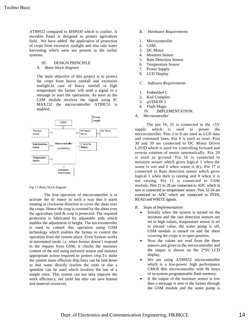
III. DESIGN PRINCIPLE
A. Basic block diagram
The main objective of this project is to protect
the crops from heavy rainfall and excessive
sunlight.In case of heavy rainfall or high
temperature the farmer will send a signal or a
message to start the operations. As soon as the
GSM module receives the signal using IC
MAX232 the microcontroller AT89C51 is
enabled.
Fig 3.1 Basic block diagram
The first operation of microcontroller is to
activate the dc motor in such a way that it starts
rotating in clockwise direction to cover the sheet over
the crops. Hence the crop is covered by the sheet over
the agriculture land & crop is protected. The required
protection is fabricated by adjustable pole which
enables the adjustment of height. The microcontroller
is used to control this operation using GSM
technology which enables the farmer to control the
operation from the remote place. Even System works
in automated mode i.e. when former doesn’t respond
to the request from GSM, it checks the moisture
content of the soil using moisture sensor and initiates
appropriate action required to protect crop.To make
the system more effective drip lines can be laid down
so that water directly reaches the roots or else a
sprinkler can be used which involves the use of a
simple rotor. This system can not only improve the
work efficiency, net yield but also can save human
and material resources.
B. Hardware Requirements
1. Microcontroller
2. GSM.
3. DC Motor
4. Moisture Sensor
5. Rain Detection Sensor
6. Temperature Sensor
7. Power Supply
8. LCD Display
C. Software Requirements
1. Embedded C
2. Keil Compiler
3. µVISION 3
4. Flash Magic
IV. IMPLEMENTATION.
A. Microcontroller
The pin 10, 31 is connected to the +5V
supply which is used to power the
microcontroller. Pins 1 to 8 are used as LCD data
and command lines. Pin 9 is used as reset. Pins
38 and 39 are connected to DC Motor Driver
L293D which is used for controlling forward and
reverse rotation of motor automatically. Pin 20
is used as ground. Pin 16 is connected to
moisture sensor which gives logical 1 when the
waste is wet and 0 when waste is dry. Pin 17 is
connected to Rain detection sensor which gives
logical 1 when theit is raining and 0 when it is
not raining. Pin 11 is connected to GSM
module. Pins 21 to 28 are connected to ADC which in
turn is connected to temperature sensor. Pins 32-34 are
connected to ADC which are connected to INTR,
READ and WRITE signals.
B. Steps of Implementation
Initially when the system is turned on the
moisture and the rain detection sensors are
set to high values, temperature sensor is set
to normal value, the water pump is off,
GSM module is turned on and the sheet
covering the crops is in open position.
Now the values are read from the three
sensors and given to the microcontroller and
the output is shown on the 2*16 LCD
display.
We are using AT89S52 microcontroller
which is a low-power, high performance
CMOS 8bit microcontroller with 8k bytes
of in-system programmable flash memory.
If the output of the moisture sensor is low
then a message is sent to the farmer through
the GSM module and the water pump is
14
Techno Buzz
Dept. of Electronics and Communication Engineering, HKBKCE

turned on so that the field can be irrigated
with the water collected through rain water
harvesting. If the output of the moisture
sensor is high then no changes are done and
it keeps on sensing.
If the Rain detection sensor output is high,
it is displayed on the LCD display, then a
message is send to the farmer through GSM
module and then a signal is sent from the
microcontroller to the DC motor to cover
the farm with the sheet and protect the crops
from heavy rainfall and the rain water is
collected and rain water harvesting is done.
If the temperature sensor output is high, it is
displayed on the LCD display, then a
message is send to the farmer through GSM
module and then a signal is sent from the
microcontroller to the DC motor to cover
the farm with the sheet and protect them
from excessive sunlight.
When the value of the Rain detection sensor
output is low i.e. there is no rain then the
microcontroller sends signal to the DC
motor and the DC motor this time rotates in
the reverse direction and the sheet covering
the crops comes back to open position.
When the value of the temperature sensor
output is low then the microcontroller sends
signal to the DC motor and the DC motor
this time rotates in the reverse direction and
the sheet covering the crops comes back to
open position. We have used 2*16 LCD to
display different types of messages.
V. ADVANTAGES,
DISADVANTAGES &
APPLICATIONS
A. ADVANTAGES:
Easy to implement
Safety against Rains and Excess Solar
Energy
Increase in Yield
It has been easier to raise crops that are
classified as genetically modified because
all of their examples have the stronger
ability to resist pests. This attribute helps
farmers with producing greater amounts of
crops or foods.
Environmental Protection
According to an Oklahoma State University
report, crops often requires less time, tools
and chemicals, and may help with reducing
greenhouse gas emissions, soil erosion and
environmental pollution.
Decrease in Food Prices
Due to higher yield and lower costs, food
prices would go down. As people in poorer
countries spend over half of their income on
food alone, this means automatic reduction
of poverty.
Decrease in Global Warming
As more plants and crops can be grown and
at more areas, including those that were
previously unsuitable for farming, oxygen in
the environment is increased, decreasing the
proportion of carbon dioxide and, in turn,
reducing global warming.
Stronger Crops
Another benefit of this technology is
believed to bring about is that crops are
engineered to withstand weather extremes
and fluctuations, which means that there will
be good quality and sufficient yields even
under a poor or severe weather condition.
B. DISADVANTAGES:
Initial Setup cost is high
Regular Maintenance of the system is
required.
Widening Gap of Corporate Sizes
This disadvantage can possibly happen
between food-producing giants and their
smaller counterparts, causing a
consolidation in the market. There would
be fewer competitors, which could increase
the risk of oligopolies and food price
increases.
Lower Level of Biodiversity
One big potential drawback of this
technology is that some organisms in the
ecosystem could be harmed, which in turn
could lead to a lower level of biodiversity.
C. APPLICATIONS
The project is used for protecting the crops from
heavy rainfall by covering the field automatically
and also to save the collected rain water. The
15
Techno Buzz
Dept. of Electronics and Communication Engineering, HKBKCE

saved water can be used for other purposes such
as feeding animals, washing, drinking, cooking
etc.
VI. CONCLUSION AND FUTURE
SCOPE
The following results are obtained
1. Protection of crops against rains and floods
2. Protection against excess Solar energy
3. Intelligent Sensor based switching
4. Automatic intimation to farmers
5. Rain water harvesting
Education and guidance for farmers, so that
they follow the guidelines, are an important way
of ensuring the protection of crops. Training
courses will increase farmers' knowledge, and
sometimes solve farmers' on-site problems.
By using solar roof tops instead of normal
panels we can generate energy from it and same
can be used for Agriculture activities.
REFERENCES
[1] Muhammad Ali Mazidi and Janice Gillispe Mazidi,
“The
8051microcontroller and embedded systems”,
Pearson
education ltd., India, 2013.
[2] Raj Kamal, “Embedded systems architecture, programming and design” Tata McGraw-Hill Ltd.
[3] National Semiconductor Corporation, ADC 0809 data
sheet,
8-bit Microprocessor compatible A/D converters with
8- channel multiplexer, national Semiconductor data
book,
October 2002.
[4] Clemens, A.J. 1990.Feedback Control for Surface
Irrigation Management in: Visions of the Future. ASAE
Publication
04-90. American Society of Agricultural Engineers,
St. Joseph, Michigan, pp. 255-260.
[5] Venkata Naga, Rohit Gunturi, microcontroller based automatic plant irrigation system, IJART April 2013
16
Techno Buzz
Dept. of Electronics and Communication Engineering, HKBKCE

INTERACTIVE DIGITAL SIGNAGE FOR SMART EDUCATION
CAMPUS 1Mr. Shaik Imam, 2Mr. Raushankumar, 3Mr. Ravi prajapati, 4Mr. Ram raksha G, 5Ms. Dhanalakshmi S
Department of ECE, HKBK College of Engineering, Nagawara, Bangalore – 560045, Karnataka, India
Abstract This project is about a remotely managed
digital signage system design considering
embedded system design rules and chara-
cteristics. Digital signage system design is
based on various methods of using comp uter
and television screens as well as other kinds of
display devices in ways that are as efficient as
possible to provide advertising and
information to people in public areas. In
modern digital signage systems, the screens
are divided into regions and layers, and the
content on the screens is made up of several
files. The goals of this study are broadcasting
information, advertisements at display
contents in public areas such as; subways,
buses, malls, city squares and control these
digital signs remotely.
INTRODUCTION
In this world everyone needs a comfort
living life. Man has researched different
technology for his
sakeoflife.Intoday’sworldofconnected,peo
plearebecomingaccustomedtoeasyaccessto
information.Whether it’s through the
internet or television, people want to be
informed and up-to-date with
thelatesteventshappeningaroundtheworld(J
.S.Lee2007).Wirednetworkconnectionsuch
asEthernethasmanylimitationsdependingo
ntheneedandtypeofconnection.Nowaday’s
peoplepreferwirelessconnectionbecausethe
ycaninteractwithpeopleeasilyanditrequirel
esstime.Themainobjectiveofthis project is
to develop a wireless notice board that
display message sent from the user and to
designasimple,easytoinstall,userfriendlysy
stem,whichcanreceiveanddisplaynoticeina
particularmannerwithrespecttodateandtime
whichwillhelptheusertoeasilykeepthetrack
ofnoticeboardeverydayandeachtimeheuses
thesystem.GSMandWi-
Fiarethewirelesstechnologyused.Temperat
ureandhumidity monitoring using sensor is
also included in our system, and we are
using camera fordisplayingthe surrounding
events so it is a multipurpose notification
system for public and utility places.
Thispaperisorganizedasfollows:Infirstsecti
onwediscusstheliteraturesurveyofvariouss
ystems.Inthenextsectionwediscusstheprop
osedsystemandthenprocessflowandthenap
plication.Inthelastsectionwe draw a
conclusion out of all the discussion
followed by a list ofreferences.
Fig.1 shows interfacing with Raspberry pi
II. Principle of Digital Signage
The Internet of Things (IoT) is not only
aboutimproving business processes, but has
also the potential to profoundly impact the life
of many citizens. Likewise the IoT can provide
17
Techno Buzz
Dept. of Electronics and Communication Engineering, HKBKCE
an useful tool for the longitudinal observation
of humanbehavior and the understanding of
behavioral patterns that can inform further IoT
technology design. Today experimentationwith
IoT technologies is predominately carried out
in lab basedtest beds. There is however an
emerging need for increased realismof the
experimentation environment, as well as
involvement ofreal end users into the
experimentation lifecycle. In this paper we
present Smart Campus, a user centric
experimental researchfacility for IoT
technologies. The current test bed
deploymentis focused on Smart Buildings, a
key building block for citiesof the future.
III. Working and Construction of Digital
Signage Unlike current lab based test beds, Smart
Campusdeeply embeds heterogeneous IoT
devices as a programmableexperimentation
substrate in a real life office environment
andmakes flexible experimentation with real
end users possible. Wepresent the architecture
realization of the current facility
andunderlying considerations that motivated
its design. Using severalrecent experimental
use cases, we demonstrate the usefulness
ofsuch experimental facilities for user-centric
IoTresearch.The recent rise of Smarter Cities
is fueled by the emer-gence of Internet of
Things (IoT) technologies, which
whenstrategically deployed throughout a city
can act as enablers forSmartness in a variety of
problem domains. The IoT facilitatesthe
effective integration of the real world with the
digital worldby providing machines and
information systems with increasedreal world
awareness and greater ability to influence real
worldprocesses. It will allow a better
understanding of the nature ofcomplex
interdependent eco-systems of dense urban life
andimproved (autonomous) decision making
capabilities providingthe means to optimize
and manage urban services in moreefficient
and effective ways.An important structural
element of Smart Cities are buildings - be it
residential or commercial - in which people
spenda significant amount of time in their
daily lives. Making thesebuildings smart with
IoT technologies will not only improvethe
quality of life and convenience of citizens in
indoor spaces,but also contribute towards more
sustainable cities throughmore efficient
utilization of scarce resources such as
energy,gas and water.
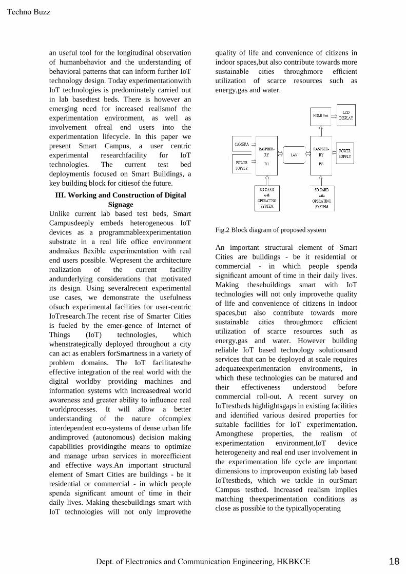
Fig.2 Block diagram of proposed system
An important structural element of Smart
Cities are buildings - be it residential or
commercial - in which people spenda
significant amount of time in their daily lives.
Making thesebuildings smart with IoT
technologies will not only improvethe quality
of life and convenience of citizens in indoor
spaces,but also contribute towards more
sustainable cities throughmore efficient
utilization of scarce resources such as
energy,gas and water. However building
reliable IoT based technology solutionsand
services that can be deployed at scale requires
adequateexperimentation environments, in
which these technologies can be matured and
their effectiveness understood before
commercial roll-out. A recent survey on
IoTtestbeds highlightsgaps in existing facilities
and identified various desired properties for
suitable facilities for IoT experimentation.
Amongthese properties, the realism of
experimentation environment,IoT device
heterogeneity and real end user involvement in
the experimentation life cycle are important
dimensions to improveupon existing lab based
IoTtestbeds, which we tackle in ourSmart
Campus testbed. Increased realism implies
matching theexperimentation conditions as
close as possible to the typicallyoperating
18
Techno Buzz
Dept. of Electronics and Communication Engineering, HKBKCE

conditions that the final solutions are expected
tobe deployed. This way design flaws or
imperfections canbe earlier detected and
evened out, thus reducing the costof roll out
and maturation time. Increased heterogeneity
ofIoT devices offers experimenters with more
experimentationoptions and resembles more
closely how IoT environmentsare expected to
be at more mature deployment stages.
Theinvolvement of real end users in the
experimentation life-cycle has a particular
importance, as the effectiveness of
IoTsolutions cannot be fully understood
without considering thehuman dimension in
experimentation. Despite good technicalmerits
of an IoT solution, it may not be easily
acceptedby technology users, e.g. due to its
intrusiveness. LikewiseIoT solutions, although
efficient in design, may not havethe desired
effect in cases where systems cannot rely
onautonomous decision making alone and
human behavior playsstill an important role.
Involving users into IoT experimentation
allows scientist also to gain a deeper
understanding ofhuman behavior, due to the
observation capabilities pervasivelydeployed
IoT technologies offer. Some of existing
testbeds have already overcome the boundaries
of the lab, spanning entire buildings with
heterogeneous devices.Theinvolvement of real
end users in the experimentation life-cycle has
a particular importance, as the effectiveness of
IoTsolutions cannot be fully understood
without considering thehuman dimension in
experimentation. Thesetestbeds however
mainly support communication level
orientedexperiments. Others are focused on
specific applications suchas energy
monitoring, thus becoming very specific
andclosed to easy reconfiguration and
effective inclusion of users.
Hardware Used:
1. Adapter 2. Raspberry pi1
3. Raspberry pi3
4. Camera
5. LAN
6. Micro SD Card
7. LCD Display
Software Used:
1. Advance IP Scanner
2. Putty
3. Yodec
4. Webiopi
Fig. 3 Shows a IP scanner window
Fig.4 shows Putty configuration
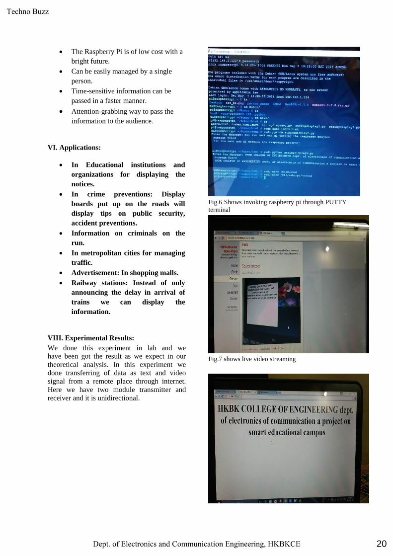
Fig.5 shows invoking raspberry pi
V. Advantages
It is a wireless system.
Text and images can be entered from
remote place.
Printing and photocopying cost is
eliminated.
Save money, energy and resource.
A lot of interaction and information
sharing occurs.
19
Techno Buzz
Dept. of Electronics and Communication Engineering, HKBKCE
The Raspberry Pi is of low cost with a
bright future.
Can be easily managed by a single
person.
Time-sensitive information can be
passed in a faster manner.
Attention-grabbing way to pass the
information to the audience.
VI. Applications:
In Educational institutions and
organizations for displaying the
notices.
In crime preventions: Display
boards put up on the roads will
display tips on public security,
accident preventions.
Information on criminals on the
run.
In metropolitan cities for managing
traffic.
Advertisement: In shopping malls.
Railway stations: Instead of only
announcing the delay in arrival of
trains we can display the
information.
VIII. Experimental Results:
We done this experiment in lab and we
have been got the result as we expect in our
theoretical analysis. In this experiment we
done transferring of data as text and video
signal from a remote place through internet.
Here we have two module transmitter and
receiver and it is unidirectional.
Fig.6 Shows invoking raspberry pi through PUTTY
terminal
Fig.7 shows live video streaming
20
Techno Buzz
Dept. of Electronics and Communication Engineering, HKBKCE

Fig.8 shows text transmission
Fig.9 shows text and image transmission
IX. Conclusion:
Now the world is moving towards automation,
so in this world if we wants to some changes
in previously used system we have to use the
new techniques. Wireless operation provides
fast transmission over long range
communication. It saves resource and time.
Data can be sent from remote locations. User
authentication is provided. Previously the
notice boards using GSM was used in that
there was the limit of messages but in our
system this limitation is eliminated. Text
messages and Multimedia data can be seen
whenever we want to see. We are using the
CCTV camera in the same system.In
conclusion, the digital signage has a huge
scope and certainly seems like the right step
towards the direction of understanding the
needs of the customer better, especially, for
the brick & mortar format of retail stores or
offices. It has found to be extremely effective
in increasing the footfall , generating
enquiries, improving brand awareness
,reducing perceived wait times, improving
operational efficiency and most importantly,
making stores and offices visit a fabulous
experience. Thus, delay in the adoption of the
digital signage will not be a wise move.
References:
[ii]. Adobe. Real-time messaging protocol
(rtmp) specification.
http://www.adobe.com/devnet/rtmp.html,
2015. Last accessed May 9, 2015.
[iii]. R. Arutyunyan. Nginx-based media
streaming server.
https://github.com/arut/nginx-rtmp-module,
2015. Last accessed May 29, 2015.
[iv]. [10] A. Dan and D. Sitaram. Load
balancing in video-on-demand servers by
allocating buffer to streams with successively
larger buffer requirements until the buffer
requirements of a stream can not be satisfied,
Aug. 6 1996. US Patent 5,544,327.
[v]. de Volkskrant. Nederland op vijfdeplek
met bijnamiljoennetflix-abonnees.
http://www.volkskrant.nl/media/nederland-
opvijfde-plek-met-bijna-miljoen-
netflixabonnees a3851031/, 2015. Last
accessed May 29, 2015.
[vi]. R. P. FOUNDATION. Raspberry pi 2
model b.
https://www.raspberrypi.org/products/
raspberry-pi-2-model-b/, 2015. Last accessed
May 29, 2015.
[vii]. K. W. R. James F. Kurose. Computer
Networking A Top-Down Approach. Pearson,
sixth edition edition, 2012. ISBN 978-0-13-
285620-1.
[viii]. D. Knight. Dietpi for raspberry pi’s.
http:
//fuzon.co.uk/phpbb/viewtopic.php?f=8&t=6,
2014. Last accessed May 29, 2015.
[ix]. W. media systems. The world’s leading
streaming technology.
http://www.wowza.com/, 2015. Last accessed
May 29, 2015
[x]. D. Meisner, B. T. Gold, and T. F.
Wenisch. Powernap: eliminating server idle
power. ACM SIGARCH Computer
Architecture News, 37(1): 205–216, 2009. doi:
10.1145/1508244.1508269.
21
Techno Buzz
Dept. of Electronics and Communication Engineering, HKBKCE

[xi]. J. Player. Jw player.
http://www.jwplayer.com/, 2015. Last
accessed May 29, 2015.
[xii]. R. W. Server. Comparing the
performance of nginx and apache web servers.
http://raspberrywebserver.com/raspberrypiclus
ter/ comparing-the-performance-of-nginx-and-
apacheweb-servers.html, 2014. Last accessed
June 5, 2015.
[xiii]. techrepublic. 10 things you should know
about microservers.
http://www.techrepublic.com/blog/10-things/
10-things-you-should-know-about-
microservers/, 8 2013. Last accessed May 9,
2015.
22
Techno Buzz
Dept. of Electronics and Communication Engineering, HKBKCE

E-MAT SYSTEM FOR JEWELLRY SECURITY SHOP
Ismail zabiulla.s1, Malashree2, Asfiya siddiqa3 , Sumitha.J4, Shireen fathima5,
1,2,3,4Students, H.K.B.K COLLEGE of engineering , S No,22/1,Nagawara Bangalore-45
5Assistant Professor, HKBK College of Engineering.
Abstract
GSM based security system are much more stout then an
ordinary security system . The ordinary systems are simply
based on the concept of sensors. They sound an alarm on
detecting movement. This system of technology has now lost its
appeal as it has become a common sighting that these alarms go
off unnecessarily. This project deals with the design &
development of a theft control system for jewellery shop,
providing a handshaking surveillance with CCTV footages
which is already a security system itself, which is being used to
prevent/control any theft attempt. The developed system makes
use of an embedded system (comprises an open hardware
microcontroller and a GSM modem) based on Global System
for Mobile communication (GSM) technology, motion sensors,
a floor mat consisting of series of push buttons, RF transmitter
& receiver and high beam lights. The DC power for the GSM is
given by 12VDC/2A power supply and 5v for microcontroller
unit/battery.
Keywords – microcontroller, GSM, SENSORS,CCTV.
1. INTRODUCTION
Most of jewellery shop owners has CCTV cameras , burglar alarms & security guards for the security of their shop but the
challenge is alarming. especially in the history of robbery
committed during night times at the jewellery showrooms in different parts of India recently during night times. Another
major challenge to prevent robbery in jewellery shops is the
lackluster attitude of the shop management in making adequate security arrangements. They deal with such valuables but do not
put burglar alarm. At several stores, the CCTV cameras are
installed but they lack recording facility and energy backup. If there is no real time check or power cut takes place, the CCTVs
are of no use. First the shop owners should cooperate with law
enforcing authorities by making it mandatory to install surveillance systems on their premises and be more vigilant
while conducting their business. In recent days we have seen
robbery is done during nights by making tunnel in the jewellery shop, the robber easily enter the shop through the tunnel dug by
him, he robs all the jewels in shop and destroy the CCTV
CAMERA or footage by taking the recorded data along with jewels. Therefore due to lack of evidence our law enforcing
authorities could not catch the real culprit. Therefore the shop
owner will have no information about it until the shop is open next morning, to overcome this issues we have work on project
which deals with the design & development of a theft control
system for jewellery shop, providing a handshaking surveillance with CCTV cameras security system , which can be used to
prevent/control any theft attempt during night times. We have
come up with some innovative idea by developing the floor mat sensors using push buttons ,this system is design for night time
surveillance when ever person step into shop and as soon as he
keeps his leg inside the shop sensors get activated a CALL &
SMS will be made to two different mobile phone numbers which will be stored in security system based on the owner
priority which will intern generate the alarm about the intruder
to the owner who is trying to enter the shop without the owner knowledge. A high beam Halogen lamp system is also
introduced in this project, as soon as pushbuttons of the mat is
pressed a Halogen bulb is turned on which prohibits the robber
to rob anything from the shop. 2. LITERATURE SURVEY
2.1. Fully Home Control System Fully Home Control
System,Systems, Process & Control (ICSPC), 2013 IEEE
Conference on :13-15 Dec. 2013, Conference Location :Kuala -
Lumpur [1]
This research work investigates the potential of `Full Home Control', which is the aim of the Home
Automation Systems in near future. The analysis and
implementation of the home automation technology using Global System for Mobile Communication (GSM) modem to
control home appliances such as light, conditional system, and
security system via Short Message Service (SMS) text messages is presented in this paper. The proposed research work is
focused on functionality of the GSM protocol, which allows the
user to control the target system away from residential using the frequency bandwidths. The concept of serial communication and
AT-commands has been applied towards development of the
smart GSM-based home automation system. 2.2. An Embedded Interface for GSM Based Car Security
System Computational Intelligence, Communication Systems
and Networks (CICSyN), 2012 Fourth International Conference on ,Conference:24-26 July 2012 , Publisher:IEEE[2]
GSM based security system are much more stout then an
ordinary security system. The ordinary systems are simply based on the concept of sensors. They sound an alarm on detecting
movement. This system of technology has now lost its appeal as
it has become a common sighting in metros where these alarms go off unnecessarily. We proposed with GSM techniques and a
better decision making process is built to make our vehicle more
secure. It is a unique wireless home/car security device that gives instant alerts on your mobile phone the moment a security
breach is detected. It is designed to alert you wirelessly through
a call burglar alarm system intercepts an intrusion. proposed an 8 bit embedded controller inter model. The control mechanism
is based on DTMF tones generated by mobile phone when the
number keys are pressed.
3. PROPOSED METHOD In this project we have designed a E-Mat security system for
jewellery shop. This project revolves around 5 major
components GSM module, motion detector, microcontroller,
Halogen lamp & Mat with push buttons fixed in it. Whenever
the motion detectors detect a motion or a person step on to the
mat the GSM module & Halogen lamp are activated, the GSM
module sends a SMS and call to prestored phone numbers, the
block diagram of the proposed method is shown below
23
Techno Buzz
Dept. of Electronics and Communication Engineering, HKBKCE

Fig. 1 : block diagram
WORKING:
The security system comprises of an Arduino Uno
microcontroller, mat sensors, motion sensors, Halogen lamp and
a standard SIM900A based GSM/GPRS modem. The GSM is
powered from any 12VDC/2A power supply unit/battery& the
whole system is powered by 5volts.
When input power is applied to the system, the
system goes into standby mode. However when the terminals of
connector is short circuited which happens when a person steps
on a mat or a motion sensors detects a motion the
preprogrammed warning message is automatically transmitted to
the concerned mobile number & the Halogen lamp turns on
effecting the eyes of a person so that he cannot rob anything
from the shop. We have connected 3 intrusion detection unit (1
electronic mat with 2 motion sensor) to the input connector .
Further, an optional “call – alert” facility is added to the security
system, which will initiate a telephone call .This option can be
used to make a “missed call” alert, in case of an intrusion
Attempt. The circuit is highly-flexible so that you can use any
SIM900A modem (and of course any Arduino Uno board). At
receiver end, owner of the shop gets the alert message to his
mobile phone through SMS & missed call alert is also provided
to him .Here mat sensors are designed by connecting push
buttons in the matrix format so that any button is pressed we get
the input to microcontroller, we have also provide some security
aspects which help the owner to enter the shop if required after
the shop is closed by providing the remote access to him
whenever the owner press the remote key a part of the mat will
deactivate and he can easily enter the shop through the
deactivated mat portion. The remote system is made of RF (TX)
of (434MHz) where RF will be connected in the module present
at the shop and TX will be connected to the remote given for the
owner. so that he could get into the shop and then deactivate the
whole system if necessary. But for deactivating the owner
should know the 1 correct key out of 7 which we have
connected in the module that deactivates the sensors other 6 key
are connected to microcontroller, a wrong key moved will
generate the alert to owner by alert message to his mobile phone
through SMS & call.
4. Conclusions
Currently ,there are different technologies available that can
assist in security based systems. In our project we have designed
& implemented an electronic mat(E-MAT) based security
system for jewellery shops and for many other applications. A
sound security system which alerts the owner by a call or SMS
if any motion is detected in the shop is developed. The owner is
provided with a ker system so that if he wishes to enter the shop
during which our proposed module is enable, he can disable the
module using the key system. The proposed project will result
in increasing the secure way to protect from thefts that happen
specially during night times.
4. RESULTS
24
Techno Buzz
Dept. of Electronics and Communication Engineering, HKBKCE

5. FUTURE SCOPE
The proposed project can be implemented on large scale in
various domain area, we can replace high beam LEDs with fog
cloud system, the mat push buttons can be replaced with piezo-
electric sensors which intern increases the efficiency by acting
as the charger during day time when costumers walk-in the
jewellary shops & banks, and same can be used for sensing
during night time. This sensors can reduces the noise of
pushbuttons and various changes can be done on basis of further
researches which intern improve the security aspects.
REFERENCES
[1] GSM based motorcycle security system ,Control and System
Graduate Research Colloquium (ICSGRC), 2011 IEEE
Conference: 27-28 June 2011, Publisher:IEEE
[2] A Remote Home Security System Based on Wireless Sensor
Network and GSM Technology Published in:Networks Security
Wireless Communications and Trusted Computing (NSWCTC),
2010 Second International Conference on (Volume:1 )
[3]WWW.GOOGLE.COM
[4] WWW.ATMEL.COM
25
Techno Buzz
Dept. of Electronics and Communication Engineering, HKBKCE

Real-Time Skeleton Tracking Using Image
Processing and Embedded System
Mohammed Hussain Shariff, Mohammed
Reyan (Authors)
Students, HKBK College of Engineering
Arfath Baig, Abhishek Singh Saini(Authors)
Students, HKBK College of Engineering
[email protected],[email protected]
Abstract— The security of information or data in
one’s computer is one of the major issues the
corporate world is facing presently. One of the most
common problems that the user’s face is they walk
away from their devices when they are logged in with
elevated privileges. This can lead to the misuse of the
devices and loss of critical and sensitive data which in
the wrong hands might prove dangerous. This project
presents the use of a web camera, an Arduino and an
ultrasonic sensor that helps the user log in to the
device when detected by the web camera and lock the
device automatically when they walk away. The user
is granted access to the device only when he matches
the database having the user’s accurate height, arm
length and leg length or is denied access to the
computer
Introduction Biometrics is the science and technology of
measuring and statistically analyzing biological
data. Biometric systems rely on specific data
about unique biological traits in order to work
effectively. These characteristics can uniquely
identify a person, replacing or supplementing
traditional security methods by providing two
major improvements personal biometrics
cannot be easily stolen and an individual does
not need to memorize passwords or codes.
A biometric system will involve running data
through algorithms for a particular result,
usually related to a positive identification of a
user or other individual. Biometric Person
Authentication has gained public attention in
recent years. It is well known that the
Fingerprint and the Iris achieve higher security
and they are already used in security systems.
On the other hand it was reported that
authentication systems using them were
circumvented by using Fake Fingers or Printed
Iris Images. The reason is that the Fingerprints
or the Iris appear on a body surface and so
become observable by using easily obtainable
sensors.
The Vein is contained within the body and
therefore it is expected to have tolerability to
the circumvention. However, it is also
reported that Authentication System using
the Vein Accepted Artifacts are used
extensively in enrollment and verification
PROPOSED METHOD A method of logging a first user in to an
computing device includes receiving an image
of the first user via a camera operable
coupled with the computing device and
determining an identity of the first user based
on the received image. If the determined
identity matches a predetermined identity,
then, based at least on the identity of the first
user matching the predetermined identity,
the first user is logged in to the computing
device.
To combine more than one security feature to
provide a better user authentication
26
Techno Buzz
Dept. of Electronics and Communication Engineering, HKBKCE
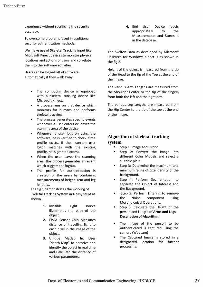
experience without sacrificing the security
accuracy.
To overcome problems faced in traditional
security authentication methods.
We make use of Skeletal Tracking input like
Microsoft Kinect devices to monitor physical
locations and actions of users and correlate
them to the software activities.
Users can be logged off of software
automatically if they walk away.
The computing device is equipped with a skeletal tracking device like Microsoft Kinect.
A process runs on that device which monitors for humans and performs skeletal tracking.
The process generates specific events whenever a user enters or leaves the scanning area of the device.
Whenever a user logs on using the software, he is verified to check if the profile exists. If the current user logon matches with the existing profile, he is granted access.
When the user leaves the scanning area, the process generates an event which triggers the logout.
The profile for authentication is created for the users by combining measurements of height, arm and leg lengths..
The fig 1 demonstrates the working of
Skeletal Tracking System in 4 easy steps as
shown.
1. Invisible Light source illuminates the path of the object.
2. FPGA Sensor Chip Measures distance of travelling light to each pixel in the image of the object.
3. Unique Matlab fn. Uses “depth Map” to perceive and identify the object in real time and Calculate the distance of various parameters.
4. End User Device reacts appropriately to the Measurements and Stores it in the database.
The Skelton Data as developed by Microsoft
Research for Windows Kinect is as shown in
the fig 2.
Height of the object is measured from the tip
of the Head to the tip of the Toe at the end of
the Image.
The various Arm Lengths are measured from
the Shoulder Center to the tip of the fingers
from both the left and the right arm.
The various Leg Lengths are measured from
the Hip Center to the tip of the toe at the end
of the Image.
Algorithm of skeletal tracking
system Step 1: Image Acquisition.
Step 2: Convert the image into different Color Models and select a suitable plain.
Step 3: Determine the maximum and minimum range of pixel density of the background.
Step 4: Perform Segmentation to separate the Object of Interest and the Background.
Step 5: Perform Filtering to remove the Noise component using Morphological Operations.
Step 6: Calculate the Height of the person and Length of Arms and Legs.
Description of Algorithm:
The Image of the person to be Authenticated is captured using the camera (Webcam)
The Captured Image is stored in a designated location for further processing.
27
Techno Buzz
Dept. of Electronics and Communication Engineering, HKBKCE
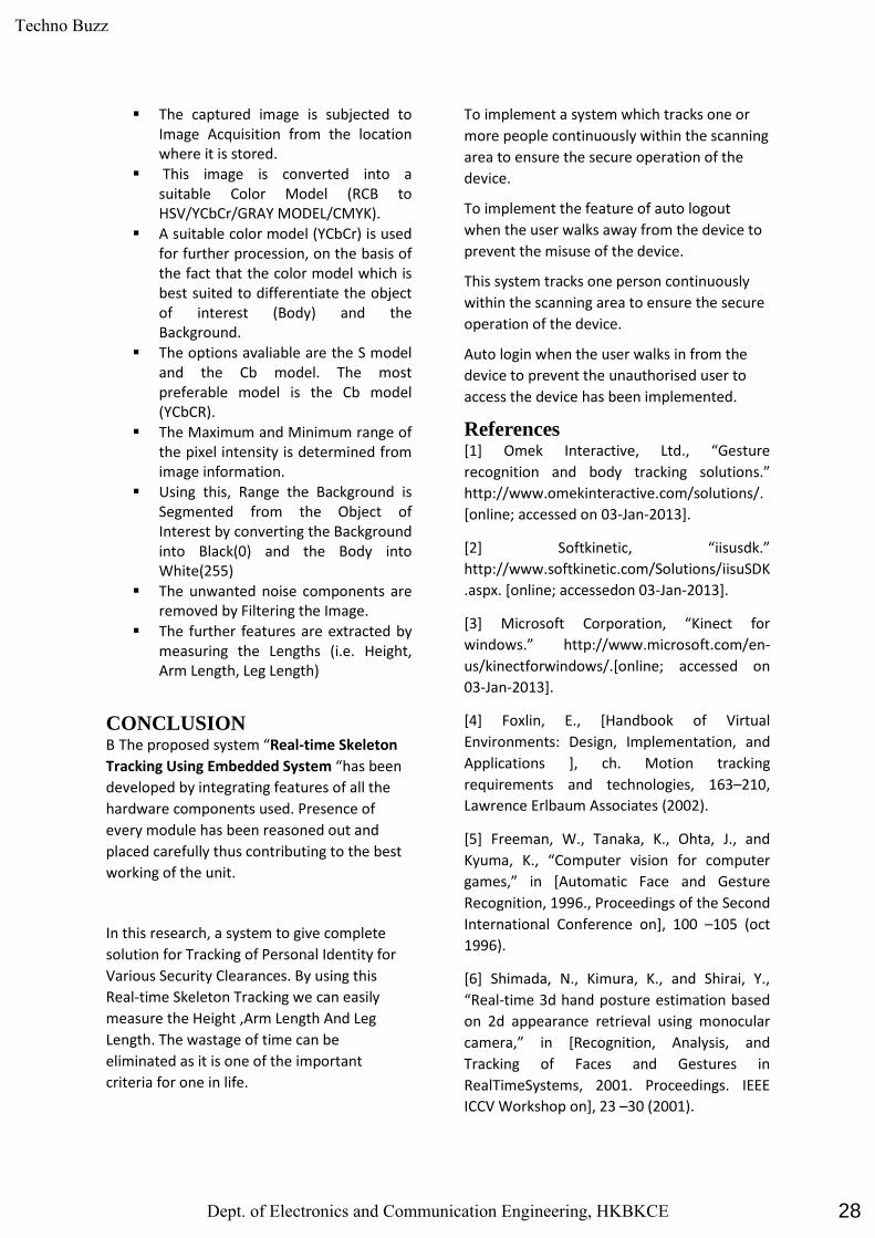
The captured image is subjected to Image Acquisition from the location where it is stored.
This image is converted into a suitable Color Model (RCB to HSV/YCbCr/GRAY MODEL/CMYK).
A suitable color model (YCbCr) is used for further procession, on the basis of the fact that the color model which is best suited to differentiate the object of interest (Body) and the Background.
The options avaliable are the S model and the Cb model. The most preferable model is the Cb model (YCbCR).
The Maximum and Minimum range of the pixel intensity is determined from image information.
Using this, Range the Background is Segmented from the Object of Interest by converting the Background into Black(0) and the Body into White(255)
The unwanted noise components are removed by Filtering the Image.
The further features are extracted by measuring the Lengths (i.e. Height, Arm Length, Leg Length)
CONCLUSION B The proposed system “Real-time Skeleton
Tracking Using Embedded System “has been
developed by integrating features of all the
hardware components used. Presence of
every module has been reasoned out and
placed carefully thus contributing to the best
working of the unit.
In this research, a system to give complete
solution for Tracking of Personal Identity for
Various Security Clearances. By using this
Real-time Skeleton Tracking we can easily
measure the Height ,Arm Length And Leg
Length. The wastage of time can be
eliminated as it is one of the important
criteria for one in life.
To implement a system which tracks one or
more people continuously within the scanning
area to ensure the secure operation of the
device.
To implement the feature of auto logout
when the user walks away from the device to
prevent the misuse of the device.
This system tracks one person continuously
within the scanning area to ensure the secure
operation of the device.
Auto login when the user walks in from the
device to prevent the unauthorised user to
access the device has been implemented.
References [1] Omek Interactive, Ltd., “Gesture
recognition and body tracking solutions.”
http://www.omekinteractive.com/solutions/.
[online; accessed on 03-Jan-2013].
[2] Softkinetic, “iisusdk.”
http://www.softkinetic.com/Solutions/iisuSDK
.aspx. [online; accessedon 03-Jan-2013].
[3] Microsoft Corporation, “Kinect for
windows.” http://www.microsoft.com/en-
us/kinectforwindows/.[online; accessed on
03-Jan-2013].
[4] Foxlin, E., [Handbook of Virtual
Environments: Design, Implementation, and
Applications ], ch. Motion tracking
requirements and technologies, 163–210,
Lawrence Erlbaum Associates (2002).
[5] Freeman, W., Tanaka, K., Ohta, J., and
Kyuma, K., “Computer vision for computer
games,” in [Automatic Face and Gesture
Recognition, 1996., Proceedings of the Second
International Conference on], 100 –105 (oct
1996).
[6] Shimada, N., Kimura, K., and Shirai, Y.,
“Real-time 3d hand posture estimation based
on 2d appearance retrieval using monocular
camera,” in [Recognition, Analysis, and
Tracking of Faces and Gestures in
RealTimeSystems, 2001. Proceedings. IEEE
ICCV Workshop on], 23 –30 (2001).
28
Techno Buzz
Dept. of Electronics and Communication Engineering, HKBKCE
[7] Bayazit, M., Couture-beil, A., and Mori, G.,
“Real-time motion-based gesture recognition
using the gpu,” in [in Proc. of the IAPR conf.
on Machine Vision Applications ], 9–12 (2009).
[8] Leap Motion, Inc, “Leap motion
controller.” https://leapmotion.com/product.
[online; accessed on 03-Jan-2013].
[9] Qualcomm Incorporated, “Gesture
recognition soccer game demo.”
http://www.qualcomm.com/media/videos/ge
sture-recognition-soccer-game-demo (aug
2012). [online; accessed on 03-Jan-2013].
[10] Kolb, A., Barth, E., Koch, R., and Larsen,
R., “Time-of-Flight Cameras in Computer
Graphics,” Computer Graphics Forum 29(1),
141–159 (2010).
[11] Andersen, M., Jensen, T., Lisouski, P.,
Mortensen, A., Hansen, M., Gregersen, T., and
Ahrendt, P., “Kinectdepth sensor evaluation
for computer vision applications – technical
report ece-tr-6,” tech. rep., Department of
Engineering Electrical and Computer
Engineering, Aarhus University, Denmark
(2012).
[12] Google inc., “Project glass google+ page.”
http://plus.google.com/+projectglass. [online;
accessed on 03-Jan-2013].
[13] MURTHY, A. V., KARAM, L. J. A MATLAB-
Based Framework for Image and Video Quality
Evaluation. QoMEX, 2013.
[14] ROGARD, E. Image Quality Assessment:
The implementation of metrics by analysis
with Matlab.CTU report, September 2012.
[15] ROGARD, E. User guide of the Image
Processing Toolbox. CTU report, June –
September 2014.
[16] JEANBLANC, E. User guide of MATLAB
Toolboxes. CTU report, June – September
2013.
[17] Shotton, J., Fitzgibbon, A., Cook, M.,
Sharp, T., Finocchio, M., Moore, R., Kipman,
A., and Blake, A., “Real-Time human pose
recognition in parts from single depth
images,” Computer Vision and Pattern
Recognition (June 2011).
[18] Bhuiyan, M. and Picking, R., “Controlled
user interfaces, what have we done and
what’s next?,”tech. rep., Centre for Applied
Internet Research (CAIR), Wrexham, UK
(2009).
Fig. 1 Skeletal Tracking System
Fig. 2 Skeleton Data
29
Techno Buzz
Dept. of Electronics and Communication Engineering, HKBKCE

Bus Safety System for School Children Using RFID
Sarvath Afreen, Daraksha Mahapara, Mahabuba Bee, Nikhat Fathima.
Mrs Swarnamba S, Assistant Professor, HKBK College of Engineering,
Abstract Millions of children need to
commute between homes to school every day.
Safer transportation of school children has been a
critical issue as it is often observed that, kids find
themselves locked in the school bus at the bus stop
after going to school, they miss the bus, or ride the
wrong bus with no way to track them. This project
intends to find yet another solution to solve this
problem by developing a bus safety system that
will control the entry and exit of students from the
buses through an energy efficient methodology.
The proposed system will control the entry and exit
of students to and from the bus using RFID (Radio
Frequency Identification) and GSM technologies to
ensure the entering and exiting of all students to
and from the school bus in a safer manner. The
process, does not require any additional action by
the student and drivers. The system will do all the
process and allow the student to be tracked while
entering and leaving the bus. If the bus journey is
successful from the source to destination, it will
send an SMS to the management to inform its
departure and arrival.
1.Introduction
School buses transfers millions of children daily in
various countries around the world. While there
many issues that might disturb the parents
regarding the travel safety of school going children,
the paper intends to look into introducing access
safety in respect of school buses through bus
tracking system that will help the school children’s
transportation in a secure and safer way. The
supervision of the regularity of students during
their entry and exit from the bus is difficult to be
controlled by drivers, which led to endangering
child safety. The phenomenon of forgetting kids
on the bus is one of the problems suffered by the
children, which has increased significantly in
recent years. This has often led to the death of
many students on account of suffocation due to the
lack of attention of derivers. This project, through
entry and exit recordings, aims to create a suitable
environment by following certain set of criteria of
security and safety for school bus that will have a
positive impact on the student and their family.
2. Proposed Method
The system block diagram of the proposed system
is shown in the following figure. The major steps
involved in the system development are explained
thereunder.
RFID Reader: The function of the RFID reader is
integrated with RFID tags. It contains the reader
module, which works as both the transmitter and
receiver of radio frequency signals. The transmitter
consists of an oscillator to create a carrier
frequency, a modulator that impacts on data
30
Techno Buzz
Dept. of Electronics and Communication Engineering, HKBKCE
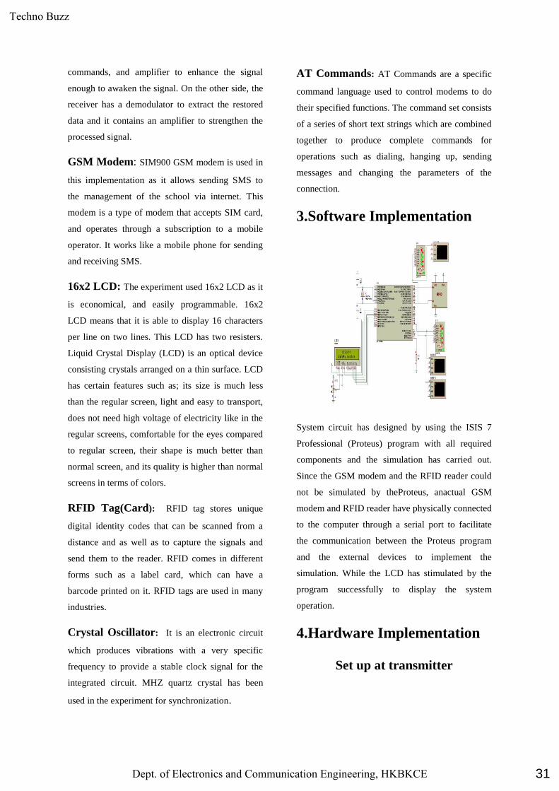
commands, and amplifier to enhance the signal
enough to awaken the signal. On the other side, the
receiver has a demodulator to extract the restored
data and it contains an amplifier to strengthen the
processed signal.
GSM Modem: SIM900 GSM modem is used in
this implementation as it allows sending SMS to
the management of the school via internet. This
modem is a type of modem that accepts SIM card,
and operates through a subscription to a mobile
operator. It works like a mobile phone for sending
and receiving SMS.
16x2 LCD: The experiment used 16x2 LCD as it
is economical, and easily programmable. 16x2
LCD means that it is able to display 16 characters
per line on two lines. This LCD has two resisters.
Liquid Crystal Display (LCD) is an optical device
consisting crystals arranged on a thin surface. LCD
has certain features such as; its size is much less
than the regular screen, light and easy to transport,
does not need high voltage of electricity like in the
regular screens, comfortable for the eyes compared
to regular screen, their shape is much better than
normal screen, and its quality is higher than normal
screens in terms of colors.
RFID Tag(Card): RFID tag stores unique
digital identity codes that can be scanned from a
distance and as well as to capture the signals and
send them to the reader. RFID comes in different
forms such as a label card, which can have a
barcode printed on it. RFID tags are used in many
industries.
Crystal Oscillator: It is an electronic circuit
which produces vibrations with a very specific
frequency to provide a stable clock signal for the
integrated circuit. MHZ quartz crystal has been
used in the experiment for synchronization.
AT Commands: AT Commands are a specific
command language used to control modems to do
their specified functions. The command set consists
of a series of short text strings which are combined
together to produce complete commands for
operations such as dialing, hanging up, sending
messages and changing the parameters of the
connection.
3.Software Implementation
System circuit has designed by using the ISIS 7
Professional (Proteus) program with all required
components and the simulation has carried out.
Since the GSM modem and the RFID reader could
not be simulated by theProteus, anactual GSM
modem and RFID reader have physically connected
to the computer through a serial port to facilitate
the communication between the Proteus program
and the external devices to implement the
simulation. While the LCD has stimulated by the
program successfully to display the system
operation.
4.Hardware Implementation
Set up at transmitter
31
Techno Buzz
Dept. of Electronics and Communication Engineering, HKBKCE
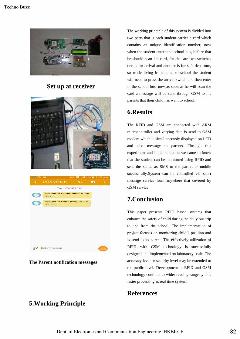
Set up at receiver
The Parent notification messages
5.Working Principle
The working principle of this system is divided into
two parts that is each student carries a card which
contains an unique identification number, now
when the student enters the school bus, before that
he should scan his card, for that are two switches
one is for arrival and another is for safe departure,
so while living from home to school the student
will need to press the arrival switch and then enter
in the school bus, now as soon as he will scan the
card a message will be send through GSM to his
parents that their child has went to school.
6.Results
The RFID and GSM are connected with ARM
microcontroller and varying data is send to GSM
modem which is simultaneously displayed on LCD
and also message to parents. Through this
experiment and implementation we came to know
that the student can be monitored using RFID and
sent the status as SMS to the particular mobile
successfully.System can be controlled via short
message service from anywhere that covered by
GSM service.
7.Conclusion
This paper presents RFID based systems that
enhance the safety of child during the daily bus trip
to and from the school. The implementation of
project focuses on monitoring child’s position and
is send to its parent. The effectively utilization of
RFID with GSM technology is successfully
designed and implemented on laboratory scale. The
accuracy level or security level may be extended to
the public level. Development in RFID and GSM
technology continue to wider reading ranges yields
faster processing as real time system.
References
32
Techno Buzz
Dept. of Electronics and Communication Engineering, HKBKCE
[1] C. Kumar, “RFID based embedded system for
vehicle tracking and prevention of road accident”.
International Journal of Engineering Research-,
Vol.1, No. 6, pp3-5, 2012.
[2] h.ben, & abdullah, k., “smart tracking system
for school buses using passive rfid technology to
enhance child safety”. traffic and logistics
engineering-,.vol.1,no.2,pp.191-196,2013..
[3] S. Shafaat, UAE launches smart school buses
to improve students safety system to offer parents
[4] Anon., 2011. Smart school bus monitoring and
trackingsystem.
33
Techno Buzz
Dept. of Electronics and Communication Engineering, HKBKCE
UNMANNED PETROL BUNK USING SMART CARD WITH
ADVANCED SECURITY SYSTEM
Sandeep Sharma1, Shiva Shankar2, Anoop3, Noorbasha4, Tanveer Baig.Z5
1, 2, 3, 4: UG Students, Dept of ECE, HKBK College of Engineering, Bangalore-45.
5: Assistant Prof. Dept. of E&C Engineering, HKBK College of Engineering, Bangalore
Abstract
In current days’ fuel stations are operated
manually. These fuel pumps are time consuming
and require more manpower. To place fuel stations
in distant area it very costly to provide excellent
facility to the consumers. All these problems are
sorted out using unmanned petrol pump which
requires less time to operate and it is effective and
can be installed anywhere the customer self-going
to avail the services. The payment is done by smart
card system.
The simple and advancement in the ARM
7 and smart card technology provides a total
security and atomization in distribution of fuel. It is
interfaced with high speed fuel dispenser which is
convenient for consumer to operate. In our system,
the password will be provided to the user via smart
card technology by the petrol pump customer has to
tap the smart card which has account details
displayed on the LCD provided by the fuel station
which will help the petrol company to create
authentication for user. Also, the distribution of the
fuel is not possible until it gets verified by the
database. In short, we provide secure system for
fuel distribution. The advancement of this project
can help industry financially.
Keywords: – ARM – Advanced Risk
Machine, LCD – Liquid Crystal Display
1. Introduction
In current days the petrol stations are
operated manually. These petrol pumps are time-
consuming and require more manpower. To place
petrol stations in distant area it very costly to
provide excellent facility to the consumers all these
problem are sorted out by the use of unmanned
power pump which requires less time to operate
and it is effective and can be installed anywhere the
customer self-going to avail the services the
payment is done by electronic clearing system.
These petrol stations easily monitor with the video
capturing and alarming system over the time by a
central control unit.
Consumers want more choices, more
speed and more convenience. They’re less
forgiving of slow pumps and outdated features and
searching for petrol station all over the place. To
upgrade market, we need a dispenser that is
reliable, user-friendly and ready to increase our
profitability. We need unmanned petrol station.
Designed from the ground up, this flexible,
dependable and scalable fuel dispenser will meet
our needs, today and tomorrow.
2. Related Work
In starting days the petrol pumps were
distributing petrol using manpower to respective
customer vehicles and was totally depends on
man‘s loyalty who was doing this job. Nowadays
industries are becoming very careful about these
things and trying to centrally control all the
production and distribution of products. For the
secure distribution of products, industries trying to
develop the new advance security system to
achieve their goals. However today petrol
distribution system is has some disadvantages
regarding with stealing of petrol, unauthorized
petrol selling & wastage of manpower etc.
3. Proposed Work
34
Techno Buzz
Dept. of Electronics and Communication Engineering, HKBKCE

The purpose of this planning is to establish
the scope of the project in terms of the major
functions, performance issues and technical
constraints. The plan will provide an estimate of the
size of the product, the effort required and the
duration. This plan will also consider the risk
encountered during the project and the strategies
for dealing with them. The plan will also discuss
the detailed schedule of various subtasks within the
project and also the resources needed to accomplish
them.
Block Diagram
Fig 1 Unmanned petrol bunk
4. Conclusions
In the world of electronics it is important
to develop the new technology to make secure the
distribution of fuel and keeping record of the same
fuel with authorization of user. Our project is one
idea which can change the face of today‘s manual
system of distribution and data keeping. The total
central access of all these activities provide the
correct approach toward security and economical
need of the industries since industry itself can
control distribution as well as keep the record of the
same fuel from thousands of miles seated in office.
In short, this project probably can be implemented
for the use of other tasks other than petrol
distribution, on large scale to achieve various goals
of industries.
REFERENCES
[1] Yan WANG, Ze ZHANG and Xuqing QIN
, "Modeling and control for hydraulic transmission
of unmanned ground vehicle[J]" , Journal of
Central South University , vol. 21 , no. 1 , pp.124 -
129 , 2014 .
[2] Yan , "Modeling and control for variable-pump
controlling variable-motor [J]" , Control Theory &
Application , vol. 29 , no. 1 , pp.41 -46 , 2012
[3] Dong Wenjie, J.A Farrell, M M Polycarpou, D
Vladimir and S. Manu , "Command filtered
adaptive backstepping [J]" , IEEE Transactions on
Control Systems Technology , vol. 20 , no. 3
, pp.566 -580 , 2012
[4] A R Ioannis, P V Kimon and A M. Wilfrido
, "A novel nonlinear backstepping controller design
for helicopters using the rotation matrix[J]" , IEEE
Transactions on Control Systems Technology , vol.
19 , no. 2 , pp.465 -473 , 2011
[5] Yaote Chang , "Block backstepping control of
MIMO systems [J]" , IEEE Transactions on
Automatic Control , vol. 56 , no. 5 , pp.1191 -1197
, 2011
[6] Lei YANG, Ma Biao and Li Heyan , "Steering
control strategy of high-speed hydrostatic drive
tracked vehicle [J]" , Transactions of the Chinese
Society for Agricultural Machinery , vol. 41 , no. 6
, pp.14 -19 , 2010
35
Techno Buzz
Dept. of Electronics and Communication Engineering, HKBKCE

36
Techno Buzz
Dept. of Electronics and Communication Engineering, HKBKCE
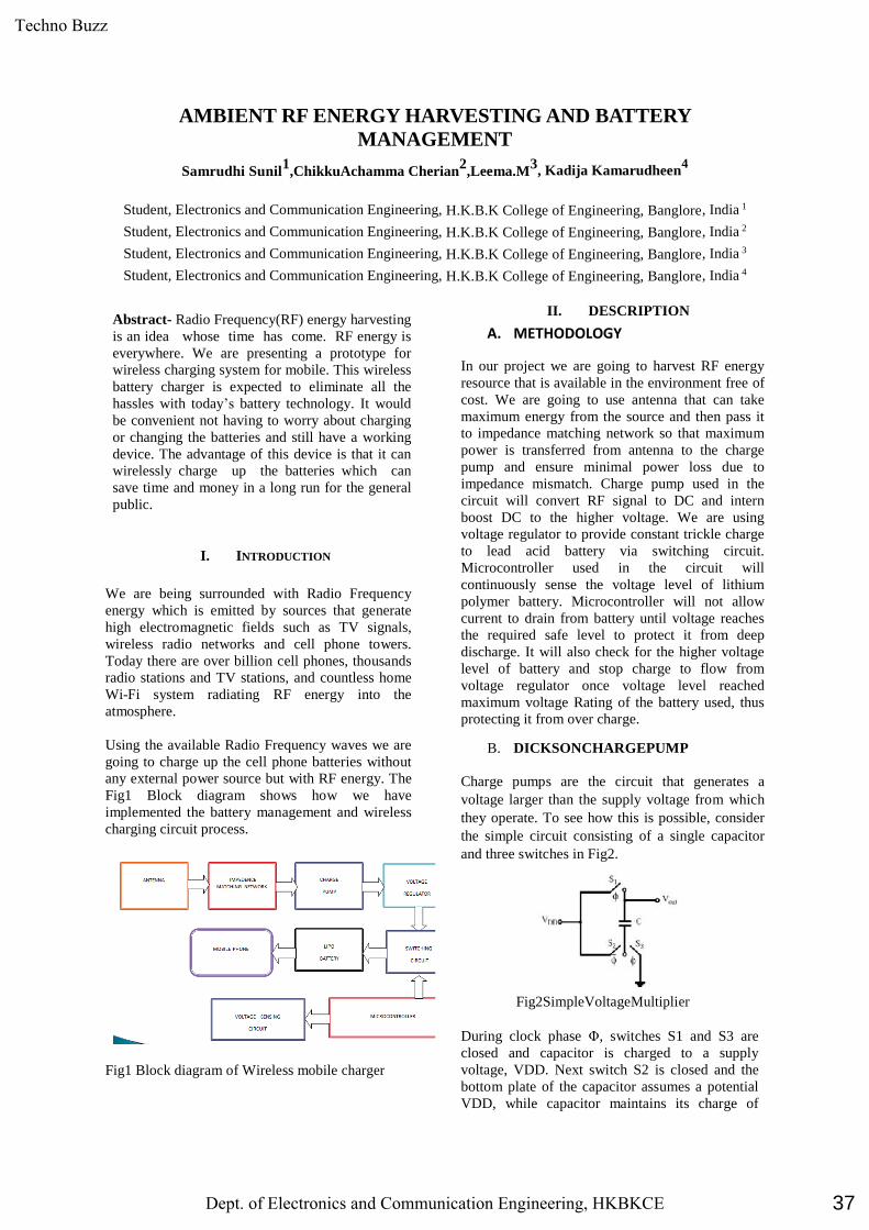
AMBIENT RF ENERGY HARVESTING AND BATTERY
MANAGEMENT
Samrudhi Sunil1
,ChikkuAchamma Cherian2
,Leema.M3
, Kadija Kamarudheen4
Student, Electronics and Communication Engineering, H.K.B.K College of Engineering, Banglore, India 1
Student, Electronics and Communication Engineering, H.K.B.K College of Engineering, Banglore, India 2
Student, Electronics and Communication Engineering, H.K.B.K College of Engineering, Banglore, India 3
Student, Electronics and Communication Engineering, H.K.B.K College of Engineering, Banglore, India 4
Abstract- Radio Frequency(RF) energy harvesting
is an idea whose time has come. RF energy is
everywhere. We are presenting a prototype for
wireless charging system for mobile. This wireless
battery charger is expected to eliminate all the
hassles with today’s battery technology. It would
be convenient not having to worry about charging
or changing the batteries and still have a working
device. The advantage of this device is that it can
wirelessly charge up the batteries which can
save time and money in a long run for the general
public.
I. INTRODUCTION
We are being surrounded with Radio Frequency
energy which is emitted by sources that generate
high electromagnetic fields such as TV signals,
wireless radio networks and cell phone towers.
Today there are over billion cell phones, thousands
radio stations and TV stations, and countless home
Wi-Fi system radiating RF energy into the
atmosphere.
Using the available Radio Frequency waves we are
going to charge up the cell phone batteries without
any external power source but with RF energy. The
Fig1 Block diagram shows how we have
implemented the battery management and wireless
charging circuit process.
Fig1 Block diagram of Wireless mobile charger
II. DESCRIPTION
A. METHODOLOGY
In our project we are going to harvest RF energy
resource that is available in the environment free of
cost. We are going to use antenna that can take
maximum energy from the source and then pass it
to impedance matching network so that maximum
power is transferred from antenna to the charge
pump and ensure minimal power loss due to
impedance mismatch. Charge pump used in the
circuit will convert RF signal to DC and intern
boost DC to the higher voltage. We are using
voltage regulator to provide constant trickle charge
to lead acid battery via switching circuit.
Microcontroller used in the circuit will
continuously sense the voltage level of lithium
polymer battery. Microcontroller will not allow
current to drain from battery until voltage reaches
the required safe level to protect it from deep
discharge. It will also check for the higher voltage
level of battery and stop charge to flow from
voltage regulator once voltage level reached
maximum voltage Rating of the battery used, thus
protecting it from over charge.
B. DICKSONCHARGEPUMP
Charge pumps are the circuit that generates a
voltage larger than the supply voltage from which
they operate. To see how this is possible, consider
the simple circuit consisting of a single capacitor
and three switches in Fig2.
Fig2SimpleVoltageMultiplier
During clock phase Φ, switches S1 and S3 are
closed and capacitor is charged to a supply
voltage, VDD. Next switch S2 is closed and the
bottom plate of the capacitor assumes a potential
VDD, while capacitor maintains its charge of
37
Techno Buzz
Dept. of Electronics and Communication Engineering, HKBKCE

VDD*C from the previous phase. This means that
during phase Φ,
(Vout-VDD).C= VDD.C Vout= 2.VDD
Thus, in the absence of dc load, an output voltage
has been generated that is twice the supply
voltage.
C. VOLAGEREGULA
TOR
TheMC34063isamonolithicswitching regulator
sub system intended for use as dc-dc converters.
This device represents as significant advancement
in the ease of implementing highly efficient and
yet simple switching power supplies. The use of
switching regulators is becoming more
pronounced over that of linear regulators because
of size reduction in new equipment design require
greater conversion efficiency. Another major
advantage is that it has increased application
flexibility of output voltage. The output can be
less than, greater than, or of opposite polarity to
that of the input voltage.
D. ATMELMICROCONTROL
LER
The AT89S51 is a low-power, high-performance
CMOS8-bit microcontroller with 4K bytes of In-
System Programmable Flash memory. The device
is manufactured using Atmel’s high-density non-
volatile memory technology and is compatible
with the industry-standard 80C51 instruction set
and pinout. The on-chip Flash allows the program
memory to be reprogrammed in-system or by a
conventional non-volatile memory programmer.
By combining a versatile 8-bit CPU with In-
System Programmable Flash on a monolithic chip,
the Atmel AT89S51 is a powerful microcontroller
which provides a highly-flexible and cost-
effective solution to many embedded control
applications.
E. A
D
C
The ADC0804 is CMOS8-bit successive
approximation A/D converter that uses a
differential potentiometric ladder—similar to the
256R products. These converters are designed to
allow operation with the NSC800 and INS8080A
derivative control bus with TRI-STATE output
latches directly driving the data bus. These A/Ds
appear like memory locations or I/O ports to the
microprocessor and no interfacing logic is needed.
Differential analog voltage inputs allow increasing
the common-mode rejection and offsetting the
analog zero input voltage value. In addition, the
voltage reference input can be adjusted to allow
encoding any smaller analog voltage span to the
full 8 bits of resolution.
F. BATT
ERY
Batteries are classified into two broad categories,
each type with advantages and disadvantages.
Primary batteries irreversible (within limits of
practically) transform chemical energy to
electrical energy. When the initial supply of
reactants is exhausted, energy cannot be readily
restored to the battery by electrical means.
Secondary batteries can be recharged: they can have
their chemical reactions reversed by supplying
electrical energy to the cell, restoring their original
composition. Some types of primary batteries used
for example for telegraph circuits, were restored to
operation by replacing the components of the
battery consumed by the chemical reaction.
Secondary batteries are not indefinitely
rechargeable due to dissipation of the active
materials, loss of electrolyte and internal
corrosion.
G. SCHOTTKYBARRIERRECTIFIERS
This series employs the Schottky Barrier principle
in a large area metal-to-silicon power diode. State
of-the-art geometry features chrome barrier metal,
epitaxial construction with oxide passivation and
metal overlap contact. Ideally suited for use as
rectifier sin low-voltage, high-frequency inverters,
freewheeling diodes, and polarity protection
diodes.
H. VOLTAGESENSINGCIRCUIT
A voltage sensor circuit is a circuit that can sense
the voltage input into it. If the voltage reaches a
certain threshold, then an indicator, such as an
LED, will turn on. This is a voltage sensor circuit,
where if in voltage reaches threshold point, then
the output will turn on. And we can build a voltage
sensor circuit, simply with a voltage comparator
chip or an op amp that can function as a voltage
comparator. A voltage comparator chip is a chip
that contains one or more op amps. Using a single
op-amp, we can determine a threshold level for
voltage. An op-amp has two inputs and one output.
The two inputs are the non-inverting input and the
inverting input. In to the inverting input, we place
the reference voltage or the threshold voltage. If
the voltage at the non-inverting terminal reaches or
goes above this level, the output will turn on.
38
Techno Buzz
Dept. of Electronics and Communication Engineering, HKBKCE
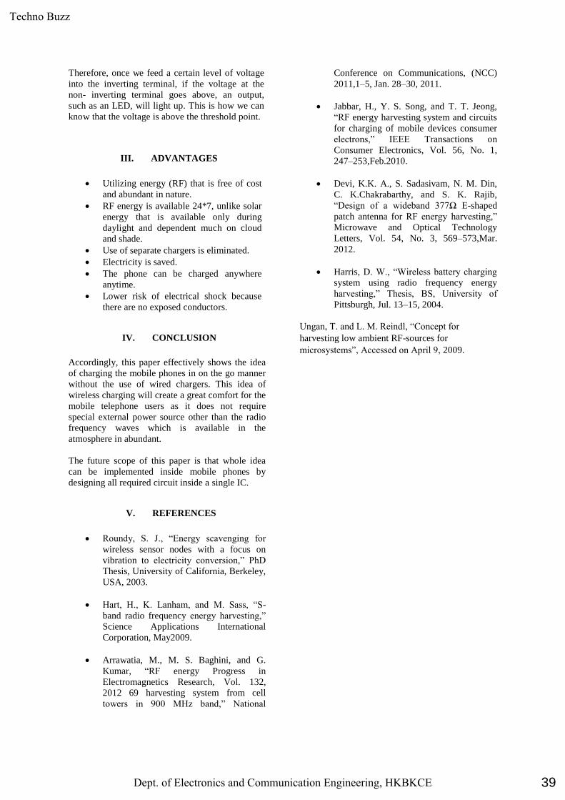
Therefore, once we feed a certain level of voltage
into the inverting terminal, if the voltage at the
non- inverting terminal goes above, an output,
such as an LED, will light up. This is how we can
know that the voltage is above the threshold point.
III. ADVANTAGES
Utilizing energy (RF) that is free of cost
and abundant in nature.
RF energy is available 24*7, unlike solar
energy that is available only during
daylight and dependent much on cloud
and shade.
Use of separate chargers is eliminated.
Electricity is saved.
The phone can be charged anywhere
anytime.
Lower risk of electrical shock because
there are no exposed conductors.
IV. CONCLUSION
Accordingly, this paper effectively shows the idea
of charging the mobile phones in on the go manner
without the use of wired chargers. This idea of
wireless charging will create a great comfort for the
mobile telephone users as it does not require
special external power source other than the radio
frequency waves which is available in the
atmosphere in abundant.
The future scope of this paper is that whole idea
can be implemented inside mobile phones by
designing all required circuit inside a single IC.
V. REFERENCES
Roundy, S. J., “Energy scavenging for
wireless sensor nodes with a focus on
vibration to electricity conversion,” PhD
Thesis, University of California, Berkeley,
USA, 2003.
Hart, H., K. Lanham, and M. Sass, “S-
band radio frequency energy harvesting,”
Science Applications International
Corporation, May2009.
Arrawatia, M., M. S. Baghini, and G.
Kumar, “RF energy Progress in
Electromagnetics Research, Vol. 132,
2012 69 harvesting system from cell
towers in 900 MHz band,” National
Conference on Communications, (NCC)
2011,1–5, Jan. 28–30, 2011.
Jabbar, H., Y. S. Song, and T. T. Jeong,
“RF energy harvesting system and circuits
for charging of mobile devices consumer
electrons,” IEEE Transactions on
Consumer Electronics, Vol. 56, No. 1,
247–253,Feb.2010.
Devi, K.K. A., S. Sadasivam, N. M. Din,
C. K.Chakrabarthy, and S. K. Rajib,
“Design of a wideband 377Ω E-shaped
patch antenna for RF energy harvesting,”
Microwave and Optical Technology
Letters, Vol. 54, No. 3, 569–573,Mar.
2012.
Harris, D. W., “Wireless battery charging
system using radio frequency energy
harvesting,” Thesis, BS, University of
Pittsburgh, Jul. 13–15, 2004.
Ungan, T. and L. M. Reindl, “Concept for
harvesting low ambient RF-sources for
microsystems”, Accessed on April 9, 2009.
39
Techno Buzz
Dept. of Electronics and Communication Engineering, HKBKCE
Related Documents