T-700

Welcome message from author
This document is posted to help you gain knowledge. Please leave a comment to let me know what you think about it! Share it to your friends and learn new things together.
Transcript
Leviton Voice & D
ata Division
T-700: Structured Cabling Systems
ww
w.levitonvoicedata.com
Leviton Voice & Data Division Headquarters2222 - 222nd St. S.E.Bothell, WA 98021-4422 USA(800) 722-2082International: (425) 486-2222
Leviton Manufacturing Co, Inc.59-25 Little Neck ParkwayLittle Neck, NY 11362 USA(800) 833-3532
Leviton Canada165 Hymus Blvd.Point-Claire, Quebec Canada H9R-1E9(514) 954-1840
Mexico - Leviton S.A. de C.V.Arista 54-A Col. Argentina Mexico, D.F. 11270Mexico52-55-5386-0073
Australia - Leviton Voice & Data DivisionSte 3, 263-267 City RoadSouth Melbourne, VA 3205 Australia61-3-9686-7400
Leviton China Ste 2212, Everbright, #6 Fuxingmen Wai St.Xi Cheng District, Beijing 100045 China86-10-6856-1169
An ISO 9001 Company
ARGENTINA
AUSTRALIA
BELGIUM
BELIZE
BRAZIL
CANADA
CHINA
CHILE
Leviton Voice & Data Products are available in 48 countries and all 50 states. Call us for a contact near you or visit www.levitonvoicedata.com
COLOMBIA
COSTA RICA
CZECH REPUBLIC
DOMINICAN REPUBLIC
ECUADOR
EL SALVADOR
EGYPT
FRANCE
GERMANY
GUATEMALA
HONDURAS
HONG KONG
INDIA
ISRAEL
JAPAN
KOREA
LEBANON
MALAYSIA
MEXICO
THE NETHERLANDS
NEW ZEALAND
NORWAY
NICARAGUA
PANAMA
PARAGUAY
PERU
THE PHILIPPINES
POLAND
PORTUGAL
PUERTO RICO
ROMANIA
SAUDI ARABIA
SINGAPORE
SPAIN
SWITZERLAND
TAIWAN
UNITED KINGDOM
UNITED STATES
URUGUAY
VENEZUELA
© Copyright 2003 Leviton Manufacturing Co., Inc. Little Neck, NY 11362-2591. All rights reserved. Printed in USA. USA and foreign patents pending. F/3 - #938
T-700
Table of Contents
A. Connectors
QuickPort® UTP Copper Connectors . . . . . .A3
QuickPort Audio/Video Connectors . . . . . . .A4
Fiber Optic Connectors . . . . . . . . . . . . . . . .A6
QuickPort Shutters & Icons . . . . . . . . . . . . . .A8
Connector Interface Bezels . . . . . . . . . . . . .A8
B. Wallplates & Housings
QuickPort Decora® Multimedia Inserts . . . . .B4
QuickPort® Flush-Mount Wallplates . . . . . . .B5
QuickPort Midsize Wallplates . . . . . . . . . . . .B5
QuickPort Stainless Steel Wallplates . . . . . . .B6
QuickPort Wallplate Inserts . . . . . . . . . . . . .B6
QuickPort Modular Furniture Faceplates . . .B7
QuickPort Multimedia Outlet System . . . . . .B8
QuickPort Surface Mount Housings . . . . . .B11
Standard Wallplates . . . . . . . . . . . . . . . . . .B12
Telephone/Video Wall Jacks & Inserts . . . . .B14
Decora Telephone/Video Wall Jack Inserts . .B15
Midsize Telephone Wall Jacks . . . . . . . . . . .B15
Voice Grade Telephone Wall Jacks & Inserts .B16
Surface Mount Telephone Jacks . . . . . . . . .B18
International Wallplates . . . . . . . . . . . . . . .B19
C. Copper Components
Universal Category 6 Panels & Blocks . . . . .C3
Universal Category 5 & 5e Panels & Blocks .C4
Voice-Grade Patch Panels . . . . . . . . . . . . . . .C5
Modular Angled Patch Panels . . . . . . . . . . . .C6
QuickPort® Multimedia Panels & Blocks . . . . .C7
Rack-Mount Surge Protection . . . . . . . . . . . .C8
Performance Patch Cords . . . . . . . . . . . . . . .C9
Rack & Panel Accessories . . . . . . . . . . . . . . .C9
110 Wiring Products . . . . . . . . . . . . . . . . . .C10
66-Clip Connecting Blocks/Accessories . . .C14
Surface-Mount Mini Patch Panels . . . . . . . .C16
D. Fiber Components
Low-Profile Rack-Mount Fiber Enclosures . .D4
Universal Fiber Optic Enclosures . . . . . . . . .D5
Rack-Mount Fiber Optic Enclosures . . . . . . .D6
Wall-Mount Fiber Optic Enclosures . . . . . . .D7
Fiber Optic Cable Assemblies . . . . . . . . . . .D8
Fiber Optic Accessories . . . . . . . . . . . . . . . .D9
E. Cable Management
Slotted Duct Cable Management . . . . . . . . .E3
Hook and Loop Cable Management . . . . . .E4
Rack Cable Management . . . . . . . . . . . . . . .E5
F. Tools & Accessories
Cable Joe® Clamp-On Cable Router . . . . . . .F3
Punchdown/Termination Tools . . . . . . . . . . .F3
Fiber Optic Tool Kits . . . . . . . . . . . . . . . . . . .F4
Universal Consumables Kit . . . . . . . . . . . . . .F4
Spectro-Link MT-RJ Tool Kits . . . . . . . . . . . . .F4
Individual Fiber Optic Tools . . . . . . . . . . . . .F5
Versa-Cleave™ Tool & Accessories . . . . . . . . .F6
Tone Test Set . . . . . . . . . . . . . . . . . . . . . . . . .F7
Crimping & Stripping Tools . . . . . . . . . . . . . .F7
Craftsperson’s Handset . . . . . . . . . . . . . . . . .F8
Modular Plug Breakout Adapter . . . . . . . . . .F8
X. Tech Support
Wire Color Codes & Pin Designations . . . . .X2
USOC Codes . . . . . . . . . . . . . . . . . . . . . . . . .X4
General Installation Tips . . . . . . . . . . . . . . . .X6
Connector Termination Instructions . . . . . . .X8
Tech Notes . . . . . . . . . . . . . . . . . . . . . . . . .X15
Cable Testing Manufacturers . . . . . . . . . . .X15
Dimensional Line Art . . . . . . . . . . . . . . . . .X16
Standards Document Information Sources . .X28
Glossary . . . . . . . . . . . . . . . . . . . . . . . . . . .X29
Index . . . . . . . . . . . . . . . . . . . . . . . . . . . . . .X34

800.824.3005
800.922.6229
Applications EngineersLeviton technical experts are available during business hours toanswer your product questions. Call Leviton’s ApplicationsEngineering Department at: 1-800-824-3005 for helpful advice andtechnical support.
Sales SupportLeviton offers a wide array of printed support materials such as LineCards, Product Brochures and our Wiring Strategies Guide. Call ourSales Support Department at: 1-800-922-6229 for info.
Certified Cabling System ProgramCCS is a strong, synergized program to coordinate,controls and assures quality for all aspects of yourcabling system, including design, installation, testingand maintenance by the most highly qualifiedinstallers in the industry.Leviton guarantees anysystem installed by aCCS installer tooperate reliably andtrouble-free for thelife of the building.
Lifetime WarrantyLeviton produces the highest quality products availableand backs them with one of the strongest warrantiesin the industry. Our Lifetime Warranty on parts andperformance provides you with the assurance thatyour Leviton CCS installed system will support not onlyall current, but also any future application developedfor TIA-568-B. It covers all Leviton CCS productsagainst defects in material and workmanship for aslong as they are installed in your certified cablingsystem. And Leviton’s “Full System Certification” coversyour entire system—Fiber or Copper—from horizontalsolutions to the backbone. Future adds, moves andchanges will never put your system at risk becauseLeviton Certified Installers will perform systemmaintenance for the life of your system.
Certified Installer TrainingCCS Program Installers are carefully selected, trainedand annually re-certified to ensure you the highestquality system installation and maintenance. They areyour resource for network design, product selection,installation, testing and support. For the name of aCertified Installer in your area, please call us at1-800-922-6229.

Support & Certification
Learning CenterVisit Leviton’s on-line Learning Center for the latestin tips, tricks and techniques. It’s your personal techsupport specialist—24 hours a day, 7 days a week.
• FAQ’s - Frequently Asked Questions • Application Notes• Technical Support E-mail • Instruction Sheets & Training Animations• Do/Don’t Guide • ‘Wiring Strategies’ Installation Guide
Plus: Presentations, wiring diagrams, and other dataon products, industry topics, glossary, and links.
Spec/Design Tools On-LineAn entire website area devoted to providing theinformation contractors, specifiers, designers andarchitects need when specifying or designingstructured cabling systems.
• Component drawings to download and import directlyinto network design programs.
• Spec sheets to reference and include with design/builddocuments and bid submittals.
• Boilerplate product specification text to place into systemspec documents.
ww
w.le
viton
voice
da
ta.co
m
Graphics LibraryDownload Leviton Voice & Data product images andlogos to use in your publications. A site especiallyfor distributors and contractors who need fast,easy access to product photos for promotionsand training.
Images can be used to create:• Catalogs • Brochures• Presentations • Newsletters• Direct mail • Ads• Training materials • Web sites
Get the latest images for any subject:• Commercial structured cabling• Fiber optic products• Home and office multimedia• New products• Logos
Choose from a range of formats and platforms:• Web-ready JPGs• High resolution TIFFs or EPSs• PC and Macintosh compatible
International SupportLeviton Voice & Data’s International Sales andMarketing Department supports a worldwidemarket that includes 47 countries in Asia,Australia, Central America, Europe, North Americaand South America, and is growing daily. Call forinformation about our international CCS programand unique internationalproduct solutions.
Hablamas Español.1-425-486-2222
Terms & Logos
The following terms and logos are used throughout this catalog to help users quickly identify specialproduct features. For a more general listing of telecom terms and concepts, please see the Glossaryin the back of this catalog, page X29.
QUICK REFERENCE GUIDEQUICK REFERENCE GUIDE
eXtreme® 6+Leviton’s Category 6 solution. Includes connectors, patchcords and QuickPort patch panels. Exceeds TIA specificationsfor channel, link and component-ratedCategory 6 systems.
GigaMax™ 5eLeviton’s Category 5e Channel and Component solution.Includes connectors, patch cords and universal panels.Exceeds TIA specifications for channel- andcomponent-rated Category 5e systems.
Category 5Leviton’s Category 5 solution for fast reliable voice and dataapplications from frame to workstation. Includes connectors,patch cords and universal panels. Exceeds TIAspecifications for channel and category-ratedCategory 5 systems.
Opt-X™
The Opt-X Fiber System incorporates a wide range of fiberoptic components, including adapters, mounting plates,connectors, enclosures, cable assemblies,tools, consumables and workstation products.The Thread-Lock and Spectro-Link (MT-RJ)systems are part of the Opt-X system.
Spectro-Link™
Spectro-Link is our innovative system of MT-RJ connectors,patch cords, adapters and tools. High-density, field-configurable and craft-friendly.
Thread-Lock®
Thread-Lock offers fiber optic solutions in ST®, FC and SCstyles, including connectors, patch cords, adapters and tools.Reusable connectors make field-installation simple andcost-effective.
Versa-Cleave™
The Versa-Cleave tool is your award-winning solution forcleaving fiber perfectly every time.
Versi-Duct™
Leviton's versatile horizontal and vertical slotted duct systemfor fiber and copper cable organization and management. Ahigh-quality system with a variety of solution-basedaccessories.
QuickPort®
Leviton’s extensive line of snap-in modulesallows complete field-configurability for theinstaller. Leviton QuickPort housings, such aswallplates, MOS housings and modularfurniture faceplates can be configured with acustom combination of QuickPort moduleswhich easily snap in or out of ports.
Decora®
The original Decora QuickPort module receptive wallplate isdesigned to match Decora electrical outlets manufacturedby Leviton.
Lifetime Performance WarrantyLeviton Voice & Data Division offers a Lifetime PerformanceWarranty when approved components are installed by aLeviton Certified Installer through the Certified CablingSystem (CCS) program.
TIA GuidelinesThe TIA, or Telecommunications Industries Association,(formerly referred to as the TIA/EIA) is the industryregulatory body which define industry standards, such asthe following:TIA-568-B: Commercial Building
Telecommunications Cabling StandardTIA-569-B: Commercial Building Standards for
Telecommunications Pathways & SpacesTIA-570: Residential and Light Commercial Wiring
StandardTIA-606: Administration Standard for the
Telecommunications Infrastructure ofCommercial Buildings
TIA-607: Telecommunications Bonding andGrounding Standard
Tech Note, Features, StylesThese icons are found throughout this catalog toindicate additional information about a givenproduct. They point out unique features andconfigurations, or direct you to thesupport section where you might finddiagrams or other technical notes tohelp you in understanding, choosing orusing Leviton products.

QuickPort® UTP Copper Connectors A3
QuickPort Audio/Video Connectors A4
Fiber Optic Connectors A6
QuickPort Shutters & Icons A8
Connector Interface Bezels A8

Fibe
r Com
pone
nts
Fibe
r Com
pone
nts
Cab
le M
anag
emen
tCab
le M
anag
emen
tTo
ols
& A
cces
sorie
sTo
ols
& A
cces
sorie
sCop
per
Com
pone
nts
Cop
per
Com
pone
nts
Wal
lpla
tes
& H
ousi
ngs
Wal
lpla
tes
& H
ousi
ngs
Con
nect
ors
Con
nect
ors
Tech
Sup
port
Tech
Sup
port
Customer Service: 800.722.2082www.levitonvoicedata.com A2
Related Products
QUICKPORT DECORA QUICKPORT DECORA MULMULTIMEDIA INSERTSTIMEDIA INSERTS
Add QuickPort compatibility to any Decora Wallplate (Page B4).
QUICKPORT FLUSH-MOUNTQUICKPORT FLUSH-MOUNTWWALLPLAALLPLATESTES
Single- or dual-gang, standard and midsize wallplates in nylon, urea or
stainless steel (Page B6).
MULMULTIMEDIA OUTLET SYTIMEDIA OUTLET SYSTEM (MOS)STEM (MOS)Flexible wallplate system ideal for networks
with high volume adds, moves and changes (Page B8).
ConnectorsAll Leviton copper and fiber QuickPort connectors are designed to fit into anyQuickPort style housing, including wallplates, multimedia outlets, surface mounthousings, modular furniture, patch panels and mounting plates. This means you canbring optical fiber, UTP copper, speaker wire and coaxial cable together in onehousing, with easy adds, moves and changes. Check out the following pages forLeviton’s complete selection of high-quality, high performance copper, fiber andaudio/video connectors.
QUICKPORT FIELD-CONFIGURABLEQUICKPORT FIELD-CONFIGURABLEPPAATCH PTCH PANELSANELS
Configure your own QuickPort patch panel (Page C7).
FIBER OPTIC MOUNTING PLAFIBER OPTIC MOUNTING PLATESTESAND ENCLOSURESAND ENCLOSURES
Feature-loaded, low cost enclosures for fiber or mixed media (Page D3).
FIBER OPTIC FIBER OPTIC TTOOL KITSOOL KITSFiber tool kits for SC, ST, FC, MT-RJ and LC,mechanical or epoxy connectors (Page F4).
110-STYLE PUNCHDO110-STYLE PUNCHDOWN WN TTOOLOOLFor punching down and trimming UTP
Copper connectors (Page F8).
DIADIAGRAMS &GRAMS & INSTRUCTIONSINSTRUCTIONSIn our appendix, find step-by-steptermination instructions, as well as
dimensional diagrams for copper, fiber andmultimedia connectors (Section X).
T-70
0
Int’l: 425.486.2222 Canada: 800.405.5320
Connectors
Connectors
Fax: 4
25
.48
3.5
27
0
Int’l Fax: 42
5.4
85
.91
70
C
anada Fax: 80
0.5
63
.18
53
w
ww
.levitonvoicedata.com
A3
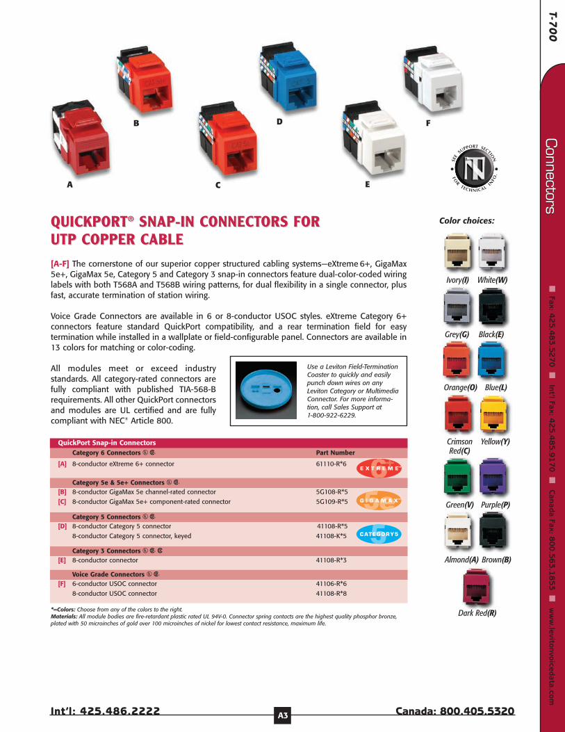
[A-F] The cornerstone of our superior copper structured cabling systems—eXtreme 6+, GigaMax5e+, GigaMax 5e, Category 5 and Category 3 snap-in connectors feature dual-color-coded wiringlabels with both T568A and T568B wiring patterns, for dual flexibility in a single connector, plusfast, accurate termination of station wiring.
Voice Grade Connectors are available in 6 or 8-conductor USOC styles. eXtreme Category 6+connectors feature standard QuickPort compatibility, and a rear termination field for easytermination while installed in a wallplate or field-configurable panel. Connectors are available in13 colors for matching or color-coding.
All modules meet or exceed industrystandards. All category-rated connectors arefully compliant with published TIA-568-Brequirements. All other QuickPort connectorsand modules are UL certified and are fullycompliant with NEC® Article 800.
QUICKPORTQUICKPORT®® SNAP-IN CONNECTSNAP-IN CONNECTORS FOR ORS FOR UTP COPPER CUTP COPPER CABLEABLE
A
B
C
D
E
F
Use a Leviton Field-TerminationCoaster to quickly and easilypunch down wires on anyLeviton Category or MultimediaConnector. For more informa-tion, call Sales Support at 1-800-922-6229.
[A] 8-conductor eXtreme 6+ connector 61110-R*6
QuickPort Snap-in ConnectorsCategory 6 Connectors US Part Number
Category 5e & 5e+ Connectors US[B] 8-conductor GigaMax 5e channel-rated connector 5G108-R*5
[C] 8-conductor GigaMax 5e+ component-rated connector 5G109-R*5
Category 5 Connectors US[D] 8-conductor Category 5 connector 41108-R*5
8-conductor Category 5 connector, keyed 41108-K*5
Category 3 Connectors US 3[E] 8-conductor connector 41108-R*3
Voice Grade Connectors US[F] 6-conductor USOC connector 41106-R*6
8-conductor USOC connector 41108-R*8
*=Colors: Choose from any of the colors to the right. Materials: All module bodies are fire-retardant plastic rated UL 94V-0. Connector spring contacts are the highest quality phosphor bronze,plated with 50 microinches of gold over 100 microinches of nickel for lowest contact resistance, maximum life.
Ivory(I) White(W)
Grey(G) Black(E)
Orange(O) Blue(L)
CrimsonRed(C)
Yellow(Y)
Green(V) Purple(P)
Almond(A) Brown(B)
Dark Red(R)
Color choices:
Fibe
r Com
pone
nts
Fibe
r Com
pone
nts
Cab
le M
anag
emen
tCab
le M
anag
emen
tTo
ols
& A
cces
sorie
sTo
ols
& A
cces
sorie
sCop
per
Com
pone
nts
Cop
per
Com
pone
nts
Wal
lpla
tes
& H
ousi
ngs
Wal
lpla
tes
& H
ousi
ngs
Con
nect
ors
Con
nect
ors
Tech
Sup
port
Tech
Sup
port
Customer Service: 800.722.2082www.levitonvoicedata.com A4
[A-F] Audio/Video Adapters U Ivory White Almond Black Grey
*= RCA-110 Connector Inner Barrel Color: Orange(O), Red(R), White(W), Yellow(Y)Materials: All module bodies are fire-retardant plastic rated UL 94V-0. Part numbers shown are for individual polybag packages in standard cartons. Some carded and contractor packs also available. Call customer service at 1-800-722-2082.
[A] BNC Adapter, nickel-plated 41084-BIF 41084-BWF 41084-BAF 41084-BEF 41084-BGF
BNC Adapter, gold-plated 40832-BI 40832-BW 40832-BA -- --
[B] F-type Adapter, nickel-plated 41084-FIF 41084-FWF 41084-FAF 41084-FEF 41084-FGF
F-type Adapter, gold-plated 40831-BI 40831-BW 40831-BA -- --
[C] S-Video module, 110 termination 40734-SVI 40734-SVW 40734-SVA 40734-SVE 40734-SVG
[D] Blank Insert (pack of 10) 41084-BIB 41084-BWB 41084-BAB 41084-BEB 41084-BGB
[E] RCA Speaker Jack, gold-plated w/black stripe 40830-BIE 40830-BWE 40830-BAE -- --
RCA Speaker Jack, gold-plated w/red stripe 40830-BIR 40830-BWR 40830-BAR -- --
RCA Speaker Jack, gold-plated w/yellow stripe 40830-BIY 40830-BWY 40830-BAY -- --
[F] RCA-110 Connector 40735-R*I 40735-R*W 40735-R*A 40735-R*E 40735-R*G
QuickPort® Snap-In Modules
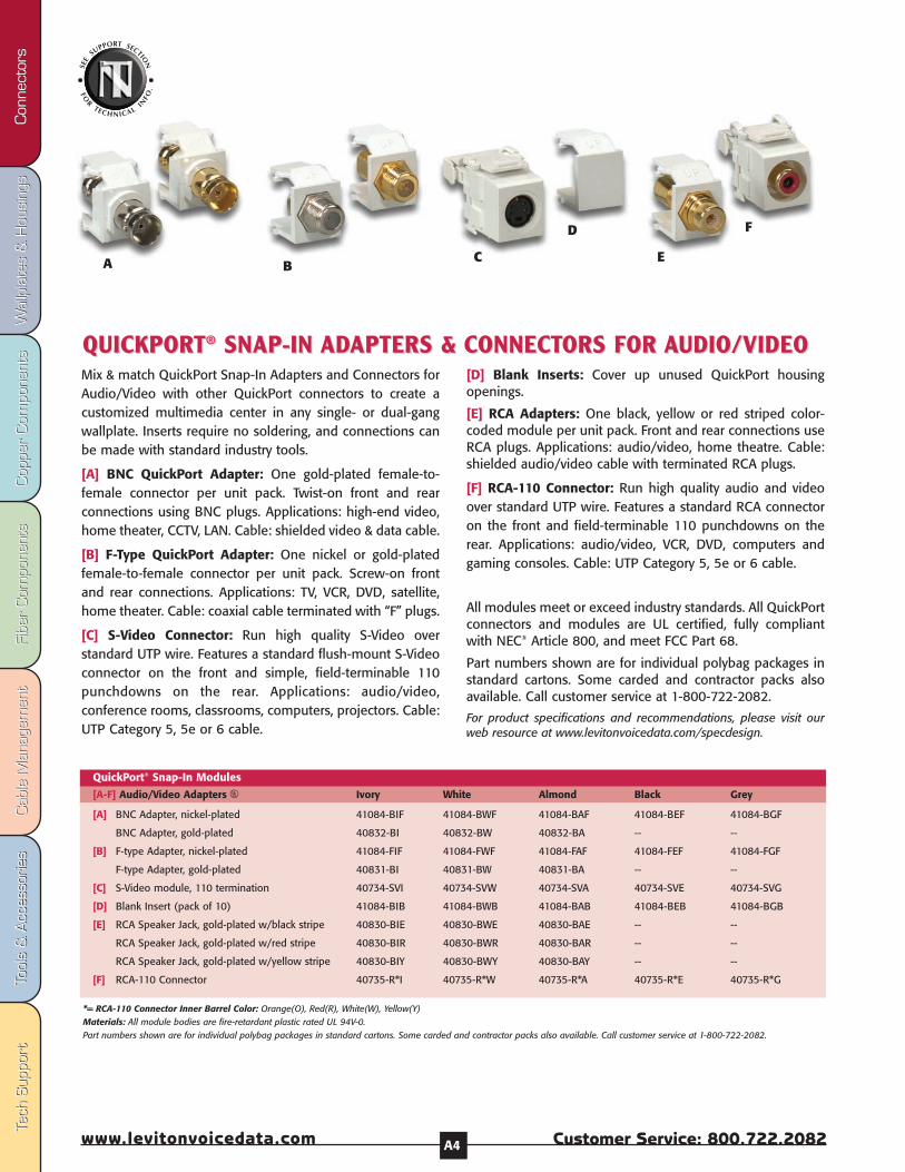
QUICKPORTQUICKPORT®® SNAP-IN SNAP-IN ADADAPTERS &APTERS & CONNECTCONNECTORS FOR ORS FOR AAUDIO/VIDEOUDIO/VIDEOMix & match QuickPort Snap-In Adapters and Connectors forAudio/Video with other QuickPort connectors to create acustomized multimedia center in any single- or dual-gangwallplate. Inserts require no soldering, and connections canbe made with standard industry tools.
[A] BNC QuickPort Adapter: One gold-plated female-to-female connector per unit pack. Twist-on front and rearconnections using BNC plugs. Applications: high-end video,home theater, CCTV, LAN. Cable: shielded video & data cable.
[B] F-Type QuickPort Adapter: One nickel or gold-platedfemale-to-female connector per unit pack. Screw-on frontand rear connections. Applications: TV, VCR, DVD, satellite,home theater. Cable: coaxial cable terminated with “F” plugs.
[C] S-Video Connector: Run high quality S-Video overstandard UTP wire. Features a standard flush-mount S-Videoconnector on the front and simple, field-terminable 110punchdowns on the rear. Applications: audio/video,conference rooms, classrooms, computers, projectors. Cable:UTP Category 5, 5e or 6 cable.
[D] Blank Inserts: Cover up unused QuickPort housingopenings.
[E] RCA Adapters: One black, yellow or red striped color-coded module per unit pack. Front and rear connections useRCA plugs. Applications: audio/video, home theatre. Cable:shielded audio/video cable with terminated RCA plugs.
[F] RCA-110 Connector: Run high quality audio and videoover standard UTP wire. Features a standard RCA connectoron the front and field-terminable 110 punchdowns on therear. Applications: audio/video, VCR, DVD, computers andgaming consoles. Cable: UTP Category 5, 5e or 6 cable.
All modules meet or exceed industry standards. All QuickPortconnectors and modules are UL certified, fully compliantwith NEC® Article 800, and meet FCC Part 68.
Part numbers shown are for individual polybag packages instandard cartons. Some carded and contractor packs alsoavailable. Call customer service at 1-800-722-2082.
For product specifications and recommendations, please visit ourweb resource at www.levitonvoicedata.com/specdesign.
A BC
D
E
F

T-70
0
Int’l: 425.486.2222 Canada: 800.405.5320
Connectors
Connectors
Fax: 4
25
.48
3.5
27
0
Int’l Fax: 42
5.4
85
.91
70
C
anada Fax: 80
0.5
63
.18
53
w
ww
.levitonvoicedata.com
A5
[A-D] Audio Adapters U Ivory White Almond
Materials: All module bodies are fire-retardant plastic rated UL 94V-0. Part numbers shown are for individual polybag packages in standard cartons. Some carded and contractor packs also available. Call customer service at 1-800-722-2082.
[A] Banana Jack Adapter, gold-plated w/black stripe 40837-BIE 40837-BWE 40837-BAE
[B] Banana Jack Adapter, gold-plated w/red stripe 40837-BIR 40837-BWR 40837-BAR
[C] Binding Post Adapter w/black stripe 40833-BIE 40833-BWE 40833-BAE
[D] Binding Post Adapter w/red stripe 40833-BIR 40833-BWR 40833-BAR
QuickPort® Snap-In Modules
[A, B] Banana Jack Adapters: One black striped or one redstriped color-coded module per unit pack. Screw-on rear-side connections. Front-side connections use standardbanana plugs. Applications: speaker connections. Cable:speaker wire terminated with banana plugs.
[C, D] Binding Post Adapters: One black striped or one redstriped color-coded module per unit pack. Screw-on rear-side connections. Optional front-side connections—eitherscrew-on or push-in—for banana plugs, speaker tip, spade
tip, or bare wire. Applications: audio speaker connections.Cable: speaker wire.
All modules meet or exceed industry standards. All QuickPortconnectors and modules are UL certified, fully compliantwith NEC® Article 800, and meet FCC Part 68.
Part numbers shown are for individual polybag packages instandard cartons. Some carded and contractor packs alsoavailable. Call customer service at 1-800-722-2082.NOTE: RCA connectors (page A4) are also suitable for Video applications.
Description Part Number
[E] Universal F-Connector (bag of 100 with installation tool) 40985-HPC
[F] Quick F-Connector (bag of 20 with installation tool) 40985-HPM
[G] One-piece Crimp-on for RG-6 quad shield (bag of 100) 40985-Q6
[H] One-piece Crimp-on for RG-59 (bag of 100) 40985-1P9
[I] One-piece Crimp-on for RG-6 (bag of 100) 40985-1P6
[J] Two-piece Crimp-on for RG-59 (bag of 100) 40985-2P9
[K] Two-piece Crimp-on for RG-6 (bag of 100) 40985-2P6
[L] Twist-On Connector for RG-59 (bag of 100) 40985-TW9
[M] Twist-On Connector for RG-6 (bag of 100) 40985-TW6
Push-on, Crimp-on and Twist-on F-Connectors
PUSH-ON,PUSH-ON, TWISTTWIST-ON & CRIMP-ON F-CONNECT-ON & CRIMP-ON F-CONNECTORSORS[E, F] Push-On F-Connectors: Quick, cost-effective 75 Ohmcoaxial cable terminations. Require no crimping tools. Quickand Universal versions accommodate RG-59, RG-6, and RG-6 Quad coax diameters.
[G-K] 1-Piece and 2-Piece Crimp-On F-Connectors:Terminates 75 Ohm coaxial cable with a crimp-on maleF-Connector. 2-piece version with separate crimp ring, orone-piece version with crimp ring attached. Both RG-59and RG-6 versions available. Crimping tool required.
[L, M] Twist-On F-Connectors: Twist-on male F-Connectorfor 75 Ohm coaxial cable. No crimping required. RG-59 andRG-6 versions.
QUICKPORTQUICKPORT®® SNAP-IN SNAP-IN ADADAPTERS &APTERS & CONNECTCONNECTORS FOR ORS FOR AAUDIOUDIO
A
BC
D
MG
E F
HI J
K
L

Fibe
r Com
pone
nts
Fibe
r Com
pone
nts
Cab
le M
anag
emen
tCab
le M
anag
emen
tTo
ols
& A
cces
sorie
sTo
ols
& A
cces
sorie
sCop
per
Com
pone
nts
Cop
per
Com
pone
nts
Wal
lpla
tes
& H
ousi
ngs
Wal
lpla
tes
& H
ousi
ngs
Con
nect
ors
Con
nect
ors
Tech
Sup
port
Tech
Sup
port
Customer Service: 800.722.2082www.levitonvoicedata.com A6
BA
EC
D
For a complete listing of FiberOptic Tools, see the Tools section,Pages F4-F6.
[A] SC Thread-Lock Connector 49884-SSC (blue) 49884-MSC (beige)
[B] FC Thread-Lock Connector 49883-SFC 49883-MFC
[C] ST Thread-Lock Connector 49882-SST 49882-MST
Thread-Lock Fiber ConnectorsDescription Singlemode Multimode
[D] Spectro-Link High-Density MT-RJ Frame-Station Connector, multimode, 62.5 µm 49888-6SF
Spectro-Link High-Density MT-RJ Frame-Station Connector, multimode, 50.0 µm 49888-5SF
[E] Spectro-Link High-Density MT-RJ Workstation Connector, multimode, 62.5 µm 49888-6SW
Spectro-Link High-Density MT-RJ Workstation Connector, multimode, 50.0 µm 49888-5SW
Spectro-Link MT-RJ Connectors
Description Part Number
Spectro-Link™ MT-RJ Fiber Connectors, Multimode[D-E] Leviton offers two styles of dual-polarity, field-configurable MT-RJ connectors.Spectro-Link Workstation connectors offer innovative push-button fiber termination, andplug directly into our MOS adapters (see page B5). Spectro-Link Frame-Station connectorsuse a cam technology to lock the fiber into a terminated position for use in frame or, withadapters, in the workstation. Both feature a pre-polished ribbon fiber ferrule thateliminates polishing. Fiber can be tested and reterminated before crimping.
FIBER OPTIC CONNECTFIBER OPTIC CONNECTORS & ORS & ADADAPTERSAPTERSThread-Lock® Reusable Fiber Connectors, Multimode and Singlemode[A-C] Got two minutes? Award-winning Thread-Lock Connectors, available in SC, FC andST® styles, are reusable, field-terminable fiber optic connectors with a simple, craft-friendlyinstallation. Use at the frame or workstation. No heat, epoxy or proprietary tools required.Feature silicone snap-on build-up sleeves for easy installation. Available in versions for usewith 62.5/125 and 50/125 multimode or singlemode fiber cable. Each box of 50connectors includes one tightening tool.

T-70
0
Int’l: 425.486.2222 Canada: 800.405.5320
Connectors
Connectors
Fax: 4
25
.48
3.5
27
0
Int’l Fax: 42
5.4
85
.91
70
C
anada Fax: 80
0.5
63
.18
53
w
ww
.levitonvoicedata.com
A7
[O] Silicon Build-up Sleeve Kit, includes one of each type of BUS (bag of 10) 49885-SBS
Sleeves for Thread-Lock Connectors
[A] ST Fast Cure Connector 49990-SST 49990-MST
[B] SC Fast Cure Connector 49990-SSC 49990-MSC
[C] FC Fast Cure Connector 49990-SFC 49990-MFC
[D] LC Fast Cure Connector with 3mm boot 49990-SL2 49990-ML2
LC Fast Cure Connector with .9mm boot 49990-SDL 49990-MDL
Fast-Cure Adhesive Connectors
Description Singlemode Multimode
Leviton QuickPort fiber adaptersfit into any Leviton QuickPortwallplate or housing, providing ahigh-density fiber-to-the-worksta-tion solution, see Section B forworkstation options.
O
FFASTAST-CURE FIBER -CURE FIBER ADHESIVE CONNECTADHESIVE CONNECTORSORSST®, FC, SC and LC Connectors [A-D] Leviton Fast Cure adhesive connectors, available in ST, SC, FC, and LC styles, arereliable, cost-effective fiber optic connectors with quick, adhesive termination. Featureprecision pre-radiused zirconia ferrules, high cable retention crimp, and patented non-optical disconnect spacer design. Available in multimode or singlemode versions.
QUICKPORT FIBER QUICKPORT FIBER ADADAPTERS & APTERS & AACCESSORIESCCESSORIES[E-J] Leviton offers QuickPort adapters to bring Thread-Lock and Fast-Cure fiber to anyQuickPort wallplate or housing. FC, SC, ST, LC and MT-RJ adapters, in various colors.
[K] SC Duplex Clip for Thread-Lock Connector, black (bag of 25) 49884-DPC
[L] SC Duplex Clip for Fast-Cure Connector, black (bag of 25) 49886-DSC
[M] LC Duplex Clip for Fast-Cure Connector, blue (bag of 25) 49886-DLS
[N] LC Duplex Clip for Fast-Cure Connector, beige (bag of 25) 49886-DLM
Duplex Clips
[E] Spectro-Link Keystone Adapter for Frame-Station Connector, dual-polarity 49889-KMA
[F] Spectro-Link QuickPort Frame-Station Adapter, for Frame-Station Connector 49889-QF*
[G] ST QuickPort Fiber Optic Adapter, SM/MM, Phos. Bronze Sleeve 41084-S*P
ST QuickPort Fiber Optic Adapter, SM/MM, Zirconia Sleeve 41084-S*Z
[H] Simplex FC QuickPort Fiber Optic Adapter, SM/MM, Phos. Bronze Sleeve 41084-F*P
Simplex FC QuickPort Fiber Optic Adapter, SM/MM, Zirconia Sleeve 41084-F*Z
[I] QuickPort Multimode Simplex SC Adapter Module, Phos Bronze 41085-M*C
QuickPort Singlemode Simplex SC Adapter Module, Zirconia Ceramic 41085-S*C
[J] QuickPort Duplex LC Adapter, SM/MM, Phos. Bronze Sleeve 41085-ML*
QuickPort Duplex LC Adapter, SM/MM, Zirconia Ceramic Sleeve 41085-SL*
Fiber Adapters
A B CD
E
F
G
H
I
J
KL
N M
Description Part Number
*=Colors: White(W), Ivory(I), Grey(G), Black(E)

Fibe
r Com
pone
nts
Fibe
r Com
pone
nts
Cab
le M
anag
emen
tCab
le M
anag
emen
tTo
ols
& A
cces
sorie
sTo
ols
& A
cces
sorie
sCop
per
Com
pone
nts
Cop
per
Com
pone
nts
Wal
lpla
tes
& H
ousi
ngs
Wal
lpla
tes
& H
ousi
ngs
Con
nect
ors
Con
nect
ors
Tech
Sup
port
Tech
Sup
port
Customer Service: 800.722.2082www.levitonvoicedata.com A8
[A] QuickPort Shutter Kit w/Leviton logo and miscellaneous icons 51084-ICN
Accessory Kit w/pre-printed icons on white paper 51084-XLB
[B] Color Label Kit w/pre-printed icons on colored paper* 51084-CLB
QuickPort Shutter & Icons
Description Part Number
QUICKPORTQUICKPORT®® SHUTTERS &SHUTTERS & ICONSICONSLeviton's field-installable QuickPort Shutters protect connectors from dust and debris witha unique, one-piece hinged door. Suitable for commercial and residential applications.Shutters feature labels and recessed windows, and they fit on Leviton Category 6, 5e, 5, 3and Voice Grade connectors, when used in a QuickPort wallplate or housing. Optionallabel kits are available. NOTE: SHUTTERSDONOTWORKWITHCONNECTORINTERFACE BEZELS.
[C] 8-Pin Connector Interface Bezel and GigaMax 5e connector (w/Leviton logo) 5G109-A*5
[D] 8-Pin Connector Interface Bezel and eXtreme 6+ connector (w/Leviton logo) 61110-A*6
[E] 8-Pin Connector Interface Bezel, white BEZEL-WHT
[F] Multimedia Connector Interface Bezel, white BEZEL-MBW
[G] MT-RJ Connector Interface Bezel, white BEZEL-MTW
[H] MT-RJ Connector Interface Bezel, black BEZEL-MTE
Connector Bezels
Description Part Number
CONNECTCONNECTOR INTERFOR INTERFAACE BEZELSCE BEZELSAdapt a variety of connector styles to Clipsal and HPM wallplates with this series of snap-on bezels. 8-Pin Connector Interface Bezels are suitable for any Category 5, 5e and 6Connectors. MT-RJ Connector Interface Bezels work with Spectro-Link Frame-StationAdapters. Multimedia Connector Interface Bezels can be used with QuickPort BNC, RCA,S-Video, Banana Jack, F-Connectors, Binding Posts, FC & ST Connectors. NOTE: BEZELS DONOT ACCOMMODATE QUICKPORT SHUTTERS.
*Color Label Kit includes: brown, green, orange, red, blue, grey, yellow and purple.
*Color choices for connector and bezel:
C
E
B
A
F
H
G
D
White(W) Grey(G) Black(E) Orange(O) Blue(L) Crimson Red(C) Yellow(Y) Green(V)
Field-installable hinged shutter protects connectorsagainst dust and debris.
Shutters fit on Category 6,Category 5e, Category 5,Category 3 and Voice Grade 8-position connectors.
Pre-printed labels, availablein accessory kits, include text(Data, Data2, Voice and Fax)and icons (Computer andTelephone) for residentialand commercial applications.
QuickPort Decora® Multimedia Inserts B4
QuickPort® Flush-Mount Wallplates B5
QuickPort Midsize Wallplates B5
QuickPort Stainless Steel Wallplates B6
QuickPort Wallplate Inserts B6
QuickPort Modular Furniture Faceplates B7
QuickPort Multimedia Outlet System B8
QuickPort Surface Mount Housings B11
Standard Wallplates B12
Telephone/Video Wall Jacks & Inserts B14
Decora Telephone/Video Wall Jack Inserts B15
Midsize Telephone Wall Jacks B15
Voice Grade Telephone Wall Jacks & Inserts B16
Surface Mount Telephone Jacks B18
International Wallplates B19
Fibe
r Com
pone
nts
Fibe
r Com
pone
nts
Cab
le M
anag
emen
tCab
le M
anag
emen
tTo
ols
& A
cces
sorie
sTo
ols
& A
cces
sorie
sCop
per
Com
pone
nts
Cop
per
Com
pone
nts
Wal
lpla
tes
& H
ousi
ngs
Wal
lpla
tes
& H
ousi
ngs
Con
nect
ors
Con
nect
ors
Tech
Sup
port
Tech
Sup
port
Customer Service: 800.722.2082www.levitonvoicedata.com B2
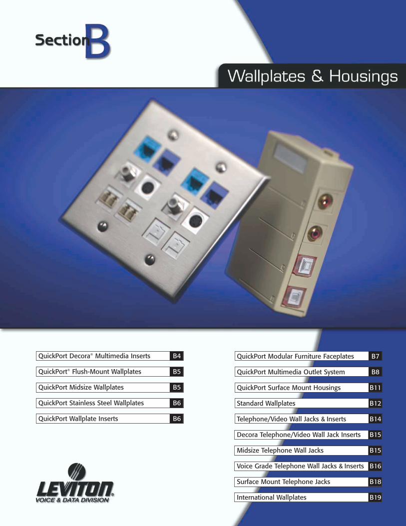
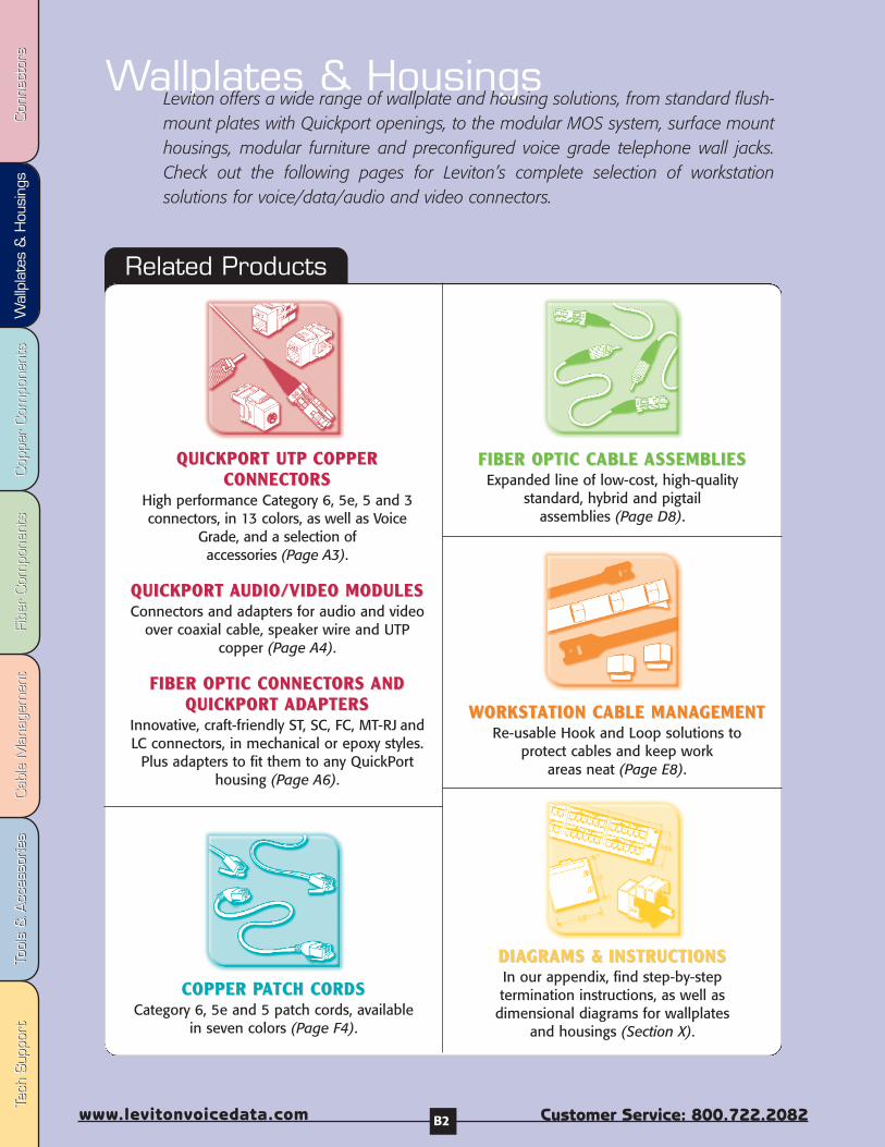
Wallplates & HousingsLeviton offers a wide range of wallplate and housing solutions, from standard flush-mount plates with Quickport openings, to the modular MOS system, surface mounthousings, modular furniture and preconfigured voice grade telephone wall jacks.Check out the following pages for Leviton’s complete selection of workstationsolutions for voice/data/audio and video connectors.
Related Products
QUICKPORT UTPQUICKPORT UTP COPPERCOPPERCONNECTCONNECTORSORS
High performance Category 6, 5e, 5 and 3connectors, in 13 colors, as well as Voice
Grade, and a selection of accessories (Page A3).
QUICKPORT QUICKPORT AAUDIO/VIDEO MODULESUDIO/VIDEO MODULESConnectors and adapters for audio and video
over coaxial cable, speaker wire and UTPcopper (Page A4).
FIBER OPTIC CONNECTFIBER OPTIC CONNECTORS ORS ANDANDQUICKPORT QUICKPORT ADADAPTERSAPTERS
Innovative, craft-friendly ST, SC, FC, MT-RJ andLC connectors, in mechanical or epoxy styles.
Plus adapters to fit them to any QuickPorthousing (Page A6).
COPPER PCOPPER PAATCH CORDSTCH CORDSCategory 6, 5e and 5 patch cords, available
in seven colors (Page F4).
FIBER OPTIC CFIBER OPTIC CABLE ABLE ASSEMBLIESASSEMBLIESExpanded line of low-cost, high-quality
standard, hybrid and pigtail assemblies (Page D8).
WWORKSTORKSTAATION CTION CABLE MANAABLE MANAGEMENTGEMENTRe-usable Hook and Loop solutions to
protect cables and keep work areas neat (Page E8).
DIADIAGRAMS &GRAMS & INSTRUCTIONSINSTRUCTIONSIn our appendix, find step-by-steptermination instructions, as well as
dimensional diagrams for wallplates and housings (Section X).
T-70
0
Int’l: 425.486.2222 Canada: 800.405.5320
Wallplates &
Housings
Fax: 4
25
.48
3.5
27
0
Int’l Fax: 42
5.4
85
.91
70
C
anada Fax: 80
0.5
63
.18
53
w
ww
.levitonvoicedata.comW
allplates & H
ousings
B3
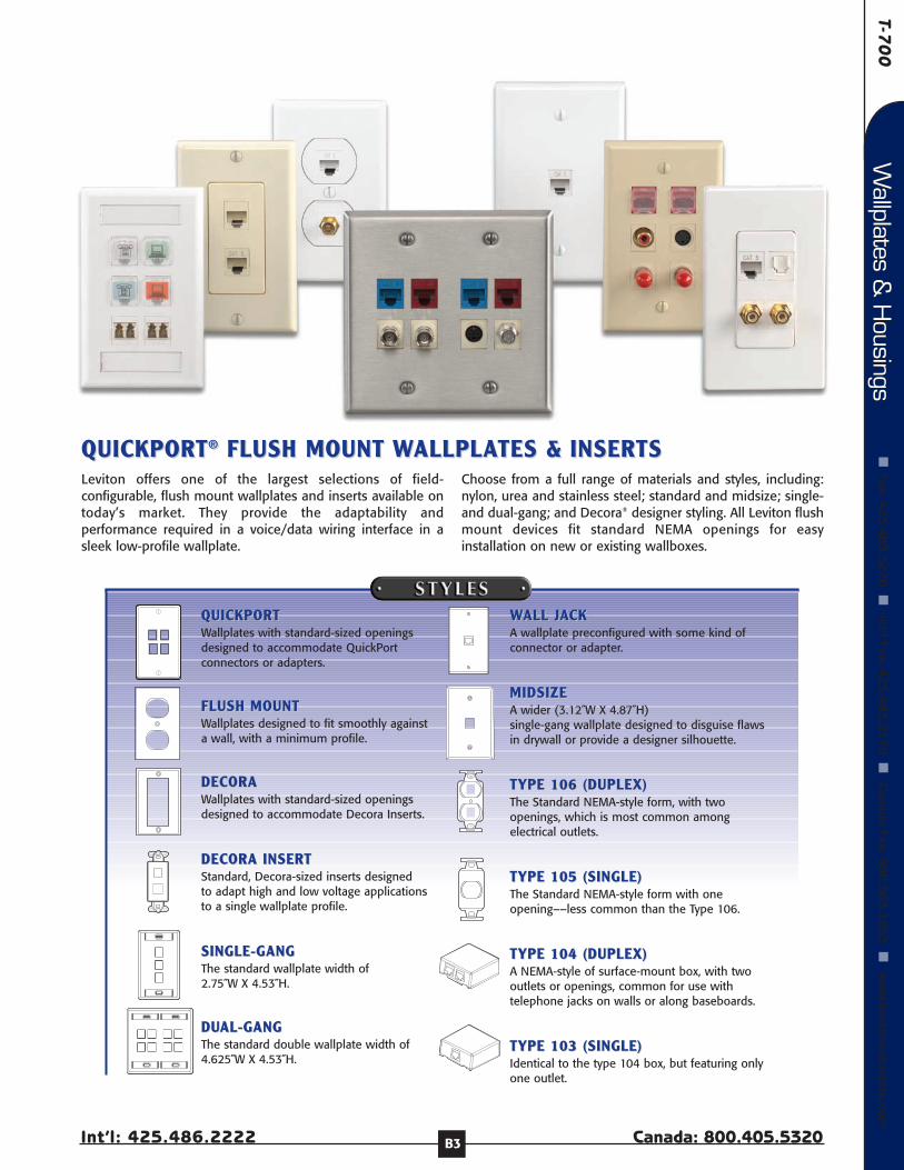
QUICKPORTQUICKPORT®® FLUSH MOUNT FLUSH MOUNT WWALLPLAALLPLATES &TES & INSERTSINSERTSLeviton offers one of the largest selections of field-configurable, flush mount wallplates and inserts available ontoday’s market. They provide the adaptability andperformance required in a voice/data wiring interface in asleek low-profile wallplate.
Choose from a full range of materials and styles, including:nylon, urea and stainless steel; standard and midsize; single-and dual-gang; and Decora® designer styling. All Leviton flushmount devices fit standard NEMA openings for easyinstallation on new or existing wallboxes.
QUICKPORTQUICKPORTWallplates with standard-sized openingsdesigned to accommodate QuickPortconnectors or adapters.
FLUSH MOUNTFLUSH MOUNTWallplates designed to fit smoothly againsta wall, with a minimum profile.
DECORA DECORA Wallplates with standard-sized openingsdesigned to accommodate Decora Inserts.
DECORA INSERTDECORA INSERTStandard, Decora-sized inserts designed to adapt high and low voltage applications to a single wallplate profile.
SINGLE-GANGSINGLE-GANGThe standard wallplate width of 2.75˝W X 4.53˝H.
DUDUAL-GANGAL-GANGThe standard double wallplate width of4.625˝W X 4.53˝H.
WWALL JALL JAACKCKA wallplate preconfigured with some kind ofconnector or adapter.
MIDSIZEMIDSIZEA wider (3.12˝W X 4.87˝H) single-gang wallplate designed to disguise flawsin drywall or provide a designer silhouette.
TYPE 106 (DUPLEX)TYPE 106 (DUPLEX)The Standard NEMA-style form, with twoopenings, which is most common amongelectrical outlets.
TYPE 105 (SINGLE)TYPE 105 (SINGLE)The Standard NEMA-style form with oneopening––less common than the Type 106.
TYPE 104 (DUPLEX)TYPE 104 (DUPLEX)A NEMA-style of surface-mount box, with twooutlets or openings, common for use withtelephone jacks on walls or along baseboards.
TYPE 103 (SINGLE)TYPE 103 (SINGLE)Identical to the type 104 box, but featuring onlyone outlet.
Fibe
r Com
pone
nts
Fibe
r Com
pone
nts
Cab
le M
anag
emen
tCab
le M
anag
emen
tTo
ols
& A
cces
sorie
sTo
ols
& A
cces
sorie
sCop
per
Com
pone
nts
Cop
per
Com
pone
nts
Wal
lpla
tes
& H
ousi
ngs
Wal
lpla
tes
& H
ousi
ngs
Con
nect
ors
Con
nect
ors
Tech
Sup
port
Tech
Sup
port
Customer Service: 800.722.2082www.levitonvoicedata.com B4
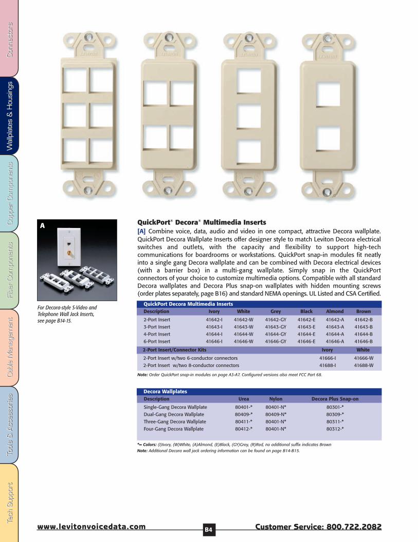
QuickPort® Decora® Multimedia Inserts[A] Combine voice, data, audio and video in one compact, attractive Decora wallplate.QuickPort Decora Wallplate Inserts offer designer style to match Leviton Decora electricalswitches and outlets, with the capacity and flexibility to support high-techcommunications for boardrooms or workstations. QuickPort snap-in modules fit neatlyinto a single gang Decora wallplate and can be combined with Decora electrical devices(with a barrier box) in a multi-gang wallplate. Simply snap in the QuickPortconnectors of your choice to customize multimedia options. Compatible with all standardDecora wallplates and Decora Plus snap-on wallplates with hidden mounting screws(order plates separately, page B16) and standard NEMA openings. UL Listed and CSA Certified.
2-Port Insert 41642-I 41642-W 41642-GY 41642-E 41642-A 41642-B
3-Port Insert 41643-I 41643-W 41643-GY 41643-E 41643-A 41643-B
4-Port Insert 41644-I 41644-W 41644-GY 41644-E 41644-A 41644-B
6-Port Insert 41646-I 41646-W 41646-GY 41646-E 41646-A 41646-B
QuickPort Decora Multimedia InsertsDescription Ivory White Grey Black Almond Brown
2-Port Insert w/two 6-conductor connectors 41666-I 41666-W
2-Port Insert w/two 8-conductor connectors 41688-I 41688-W
2-Port Insert/Connector Kits Ivory White
Note: Order QuickPort snap-in modules on page A3-A7. Configured versions also meet FCC Part 68.
A
Single-Gang Decora Wallplate 80401-* 80401-N* 80301-*
Dual-Gang Decora Wallplate 80409-* 80409-N* 80309-*
Three-Gang Decora Wallplate 80411-* 80401-N* 80311-*
Four-Gang Decora Wallplate 80412-* 80401-N* 80312-*
Decora WallplatesDescription Urea Nylon Decora Plus Snap-on
*= Colors: (I)Ivory, (W)White, (A)Almond, (E)Black, (GY)Grey, (R)Red, no additional suffix indicates Brown Note: Additional Decora wall jack ordering information can be found on page B14-B15.
For Decora-style S-Video andTelephone Wall Jack Inserts,see page B14-15.

T-70
0
Int’l: 425.486.2222 Canada: 800.405.5320
Wallplates &
Housings
Fax: 4
25
.48
3.5
27
0
Int’l Fax: 42
5.4
85
.91
70
C
anada Fax: 80
0.5
63
.18
53
w
ww
.levitonvoicedata.comW
allplates & H
ousings
B5
QuickPort® Single-Gang Multi-Port Wallplates with or withoutDesignation Windows[A,B] Single-gang flush mount wallplates offer field-configurable flexibility in an attractivesingle-piece housing. Fully compatible with all QuickPort Snap-in Modules includingconnectors or blank fillers. Use different color QuickPort modules for port identification, ortype or hand-write labels for designation windows. All windows are field-label compatible,and cover the wallplate security screw. UL Listed, CSA Certified, and are listed incompliance with NEC Article 800.
Professional-looking port identificationis fast and simple with pre-printedlabels, sold on page B20. These labelscan be used on all Leviton workstationproducts.
6-Port Wallplate 41080-6IP 41080-6WP 41080-6GP 41080-6EP 41080-6AP 41080-6BP
4-Port Wallplate 41080-4IP 41080-4WP 41080-4GP 41080-4EP 41080-4AP 41080-4BP
3-Port Wallplate 41080-3IP 41080-3WP 41080-3GP 41080-3EP 41080-3AP 41080-3BP
2-Port Wallplate 41080-2IP 41080-2WP 41080-2GP 41080-2EP 41080-2AP 41080-2BP
1-Port Wallplate 41080-1IP 41080-1WP 41080-1GP 41080-1EP 41080-1AP 41080-1BP
QuickPort Single-Gang WallplatesDescription Ivory White Grey Black Almond Brown
Description ID Windows Ivory White Grey Black6-Port Wallplate 2 42080-6IS 42080-6WS 42080-6GS 42080-6ES
4-Port Wallplate 2 42080-4IS 42080-4WS 42080-4GS 42080-4ES
3-Port Wallplate 2 42080-3IS 42080-3WS 42080-3GS 42080-3ES
2-Port Wallplate 2 42080-2IS 42080-2WS 42080-2GS 42080-2ES
1-Port Wallplate 1 42080-1IS 42080-1WS 42080-1GS 42080-1ES
QuickPort Single-Gang Wallplates w/ Designation ID Windows
Note: Housings are sold empty. Snap-in Connectors must be ordered separately. (See page A3-A7.)
Note: Housings are sold empty. Snap-in Connectors must be ordered separately. (See page A3-A7.)
QuickPort® Dual-Gang Multi-Port Wallplates with Designation Windows[C] Dual-gang flush mount wallplates with designation windows are designed in a single-piece housing and a wide choice of port counts for maximum density. Field configure withany combination of QuickPort Snap-in Modules. Use different color QuickPort modules forport identificaion, or type or hand-write labels for designation windows. All windows arefield-label compatible, and cover the wallplate security screw. QuickPort wallplates are ULListed, CSA Certified, and are listed in compliance with NEC Article 800.
12-Port Wallplate 4 42080-12I 42080-12W 42080-12G 42080-12E
8-Port Wallplate 4 42080-8IP 42080-8WP 42080-8GP 42080-8EP
6-Port Wallplate 4 42080-6IP 42080-6WP 42080-6GP 42080-6EP
4-Port Wallplate 4 42080-4IP 42080-4WP 42080-4GP 42080-4EP
3-Port Wallplate 2 42080-3IP 42080-3WP 42080-3GP 42080-3EP
2-Port Wallplate 2 42080-2IP 42080-2WP 42080-2GP 42080-2EP
1-Port Wallplate 2 42080-1IP 42080-1WP 42080-1GP 42080-1EP
Description No. of ID Windows Ivory White Grey Black
QuickPort Dual-Gang Wallplates With Designation ID Window US
QUICKPORT SINGLE- &QUICKPORT SINGLE- & DUDUAL-GANG AL-GANG WWALLPLAALLPLATESTES
A
B
C
Midsize QuickPort® Wallplates[D] Midsize wallplates provide QuickPort modularity with .375” more coverage thanstandard wallplates. Expanded silhouette provides designer look and easily hides irregulardrywall cuts or flaws around outlets. The 4.875” x 3.125” plate is .375” wider and taller, andmatches Leviton’s Midsize Wallplates for electrical devices and lighting controls. .25” depthensures a clean fit with various devices. Crafted from durable, smooth-finish nylon,wallplates fit a single-gang electrical box. UL listed and CSA certified.
6-Port Midsize QuickPort Wallplate, Nylon 41091-6IN 41091-6WN 41091-6AN 41091-6BN
4-Port Midsize QuickPort Wallplate, Nylon 41091-4IN 41091-4WN 41091-4AN 41091-4BN
3-Port Midsize QuickPort Wallplate, Nylon 41091-3IN 41091-3WN 41091-3AN 41091-3BN
2-Port Midsize QuickPort Wallplate, Nylon 41091-2IN 41091-2WN 41091-2AN 41091-2BN
1-Port Midsize QuickPort Wallplate, Nylon 41091-1IN 41091-1WN 41091-1AN 41091-1BN
QuickPort Midsize Single-Gang Wallplates, Nylon Description Ivory White Almond Brown
D

Fibe
r Com
pone
nts
Fibe
r Com
pone
nts
Cab
le M
anag
emen
tCab
le M
anag
emen
tTo
ols
& A
cces
sorie
sTo
ols
& A
cces
sorie
sCop
per
Com
pone
nts
Cop
per
Com
pone
nts
Wal
lpla
tes
& H
ousi
ngs
Wal
lpla
tes
& H
ousi
ngs
Con
nect
ors
Con
nect
ors
Tech
Sup
port
Tech
Sup
port
Customer Service: 800.722.2082www.levitonvoicedata.com
F
QuickPort Duplex 106 Insert only 41087-2IP 41087-2WP 41087-2GP 41087-2EP
QuickPort Quad 106 Insert only 41087-QIP 41087-QWP 41087-QGP 41087-QEP
QuickPort Duplex 106 InsertDescription Ivory White Grey Black
Note: Inserts are sold empty. Snap-in Connectors must be ordered separately. (See page A3-A7.)Note: Floor monuments shown for illustration only, and are not part of the Leviton product line.
Insert with one F-connector, one blank module, and brass plate w/cap 41650-F
Insert with one 6-conductor connector, one blank module, and brass plate w/cap 41650-6
Insert with one blank module and brass plate w/cap 41652
Insert with two 6-conductor jacks and brass plate w/cap 41652-6
Insert with one 6-conductor connector, one F-connector, and brass plate w/cap 41652-6F
QuickPort Duplex Floor Jack Insert w/ Brass Plate & Screw CapDescription Part Number
QuickPort® Floor Jack Insert[F] Rugged and fully field-configurable, this device provides point-of-use connectivity for abroad range of applications where convenience or building requirements dictate the use ofa floor-mounted communications outlet. Each floorplate is made of .06" thick solid brass tohold up under heavy furniture or foot traffic. When not in use, a flush-fitting brass screw capkeeps internal components free from dirt and dust.
The two individual ports are configured easily with any combination of QuickPort Snap-inModules. QuickPort floor jacks will fit standard metal boxes 3" x 2", 3" x 2 1⁄8" and larger.
E
QuickPort® Duplex/Quad 106 Insert [D, E] The QuickPort Duplex and Quad 106 Units are ideal for applications where two orfour individual modular ports are desired, within the standard ‘106/NEMA-style’ outline thatprevails among electrical outlets. Accepts all QuickPort Snap-in Modules and fits standardNEMA wallboxes and most floor boxes and monuments. A recess above each module porton the Duplex 106 Unit accommodates Leviton Designation Labels (page B20) or hand-written port ID. Uses standard duplex wallplates (sold separately, page B12). UL & CSA list-ed and NEC Article 800 compliant
QUICKPORT QUICKPORT WWALLPLAALLPLATE INSERTSTE INSERTS
QuickPort® Stainless Steel Wallphone Wallplates[C] Bring Stainless Steel elegance to your wallphone. Easily mount any standard wallphoneon this sturdy, standard-sized wallplate with durable rivets. Single port accepts any LevitonQuickPort Connector. Recessed design fits cleanly with slide-rail mechanisms.
Stainless Steel Wallphone Wallplate, recessed 4108W-1SP
Stainless Steel Wallphone Wallplate 4108W-0SP
QuickPort Stainless Steel WallplatesDescription Part Number
A QUICKPORT STQUICKPORT STAINLESS STEEL AINLESS STEEL WWALLPLAALLPLATESTES
Note: Housings are sold empty. Snap-in Connectors must be ordered separately. (See page A3-A7.)
QuickPort® Stainless Steel Single-Gang and Dual-Gang Wallplates[A-B] Leviton's single-gang and dual-gang QuickPort® Stainless Steel Wallplates provideelegant designer styling, and accept any QuickPort snap-in copper/fiber connector oradapter. Ideal in environments that demand a more durable, sanitary, easy-to-clean solution.Use different color QuickPort modules for port identification. Fit standard NEMA electricalboxes. cULus Listed, meet FCC Part 68, and are listed in compliance with TIA/EIA-568-B.
C
NOTE: Wallplate included with eachQuickPort Floor Jack Insert.
B
Note: Leviton also offers Voice-Grade Wall Phone Jacks. (See page B15.)
Single-Gang 43080-1S1 43080-1S2 43080-1S3 43080-1S4 43080-1S6 -- --
Dual-Gang -- 43080-2S2 -- 43080-2S4 43080-2S6 43080-2S8 43080-S12
QuickPort Stainless Steel WallplatesDescription 1-Port 2-Port 3-Port 4-Port 6-Port 8-Port 12-Port
D
B6

T-70
0
Int’l: 425.486.2222 Canada: 800.405.5320
Wallplates &
Housings
Fax: 4
25
.48
3.5
27
0
Int’l Fax: 42
5.4
85
.91
70
C
anada Fax: 80
0.5
63
.18
53
w
ww
.levitonvoicedata.comW
allplates & H
ousings
B7
†Fits most Herman Miller furniture including Action Office I, II, III and Ethospace Baseline. To ensure compatibility with specificmodels call Applications Engineering.*=Color choices: Ivory (I), White (W), Grey (G), Black (E)
Materials: High-impact fire-retardant plastic rated UL 94V-0.
Steelcase 9000® Series
Herman Miller Ethospace®
Baseline series (shown with49900-SE4 and Herman Miller's"Reducer" G1189A)
Haworth® Panels
2-Port 49910-S*2
4-Port (w/1 blank) 49910-S*4
4-Port Extended-depth† (w/1 blank) 49910-E*4
Note: Standard modular furniture faceplates above fit openings of approximately 1 3/8" x 2 5/8".
Standard Modular Furniture Faceplates with ID Windows
Herman
Description Part # Miller Steelcase Haworth HON Others
2-Port HM Faceplate 49910-H*2 –– –– –– ––
4-Port HM Faceplate (with 1 Blank) 49910-H*4 –– –– –– ––
Note: Herman Miller faceplates above fit openings of approximately 1.88" x 2.98".
Herman Miller Modular Furniture Faceplates
Herman
Description Part # Miller Steelcase Haworth HON Others
†4-port extended plate provides 1/2” added depth (3/4” total) for installation into shallow raceway channels, e.g., some powered channels. Compatible when used with Herman Miller G1189A Reducer available from Herman Miller dealers.
QuickPort® furniture faceplates come inmany styles to fit allmajor modularfurniture brands.
QUICKPORTQUICKPORT®® MODULAR FURNITURE FMODULAR FURNITURE FAACEPLACEPLATESTESBring a simple snap-in installation, attractive streamlined appearance and easy identifica-tion to your modular furniture environments. QuickPort Modular Furniture Faceplatesaccept all QuickPort Snap-In Modules—supporting virtually any application—and snap easi-ly and snugly into standard modular furniture. Features faceplate windows with clear plas-tic covers that allow easy insertion of ID labels. Labor-saving QuickPort jack design and tool-less plate installation simplifies installations, adds, moves and changes, and allows accessto the connectors without removing the furniture channel cover. Available in 2- and 4-portversions, and in four colors: ivory, white, grey and black. cULus Listed and CSA Certified.
Fibe
r Com
pone
nts
Fibe
r Com
pone
nts
Cab
le M
anag
emen
tCab
le M
anag
emen
tTo
ols
& A
cces
sorie
sTo
ols
& A
cces
sorie
sCop
per
Com
pone
nts
Cop
per
Com
pone
nts
Wal
lpla
tes
& H
ousi
ngs
Wal
lpla
tes
& H
ousi
ngs
Con
nect
ors
Con
nect
ors
Tech
Sup
port
Tech
Sup
port
Customer Service: 800.722.2082www.levitonvoicedata.com B8
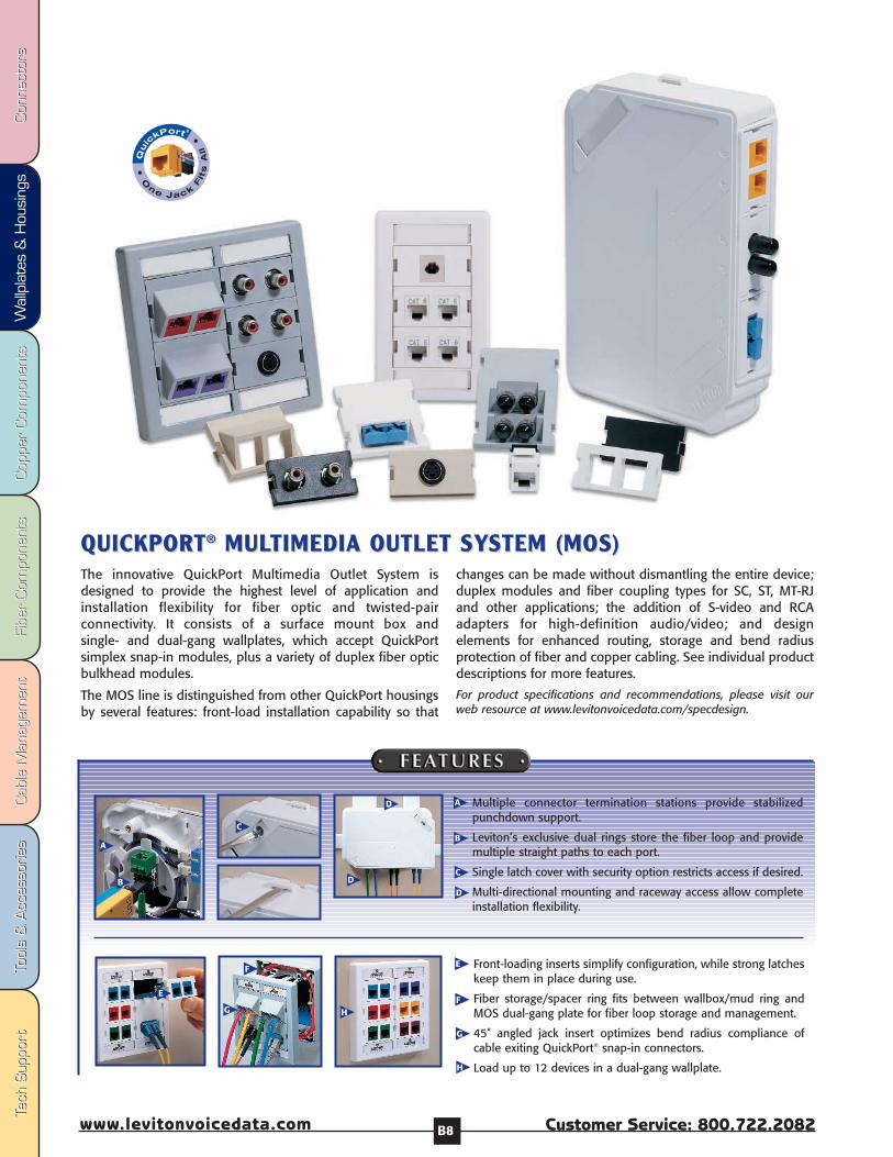
The innovative QuickPort Multimedia Outlet System isdesigned to provide the highest level of application andinstallation flexibility for fiber optic and twisted-pairconnectivity. It consists of a surface mount box andsingle- and dual-gang wallplates, which accept QuickPortsimplex snap-in modules, plus a variety of duplex fiber opticbulkhead modules.
The MOS line is distinguished from other QuickPort housingsby several features: front-load installation capability so that
changes can be made without dismantling the entire device;duplex modules and fiber coupling types for SC, ST, MT-RJand other applications; the addition of S-video and RCAadapters for high-definition audio/video; and designelements for enhanced routing, storage and bend radiusprotection of fiber and copper cabling. See individual productdescriptions for more features.
For product specifications and recommendations, please visit ourweb resource at www.levitonvoicedata.com/specdesign.
QUICKPORTQUICKPORT®® MULMULTIMEDIA OUTLET SYTIMEDIA OUTLET SYSTEM (MOS)STEM (MOS)
Multiple connector termination stations provide stabilizedpunchdown support.
Leviton’s exclusive dual rings store the fiber loop and providemultiple straight paths to each port.
Single latch cover with security option restricts access if desired.
Multi-directional mounting and raceway access allow completeinstallation flexibility.
Front-loading inserts simplify configuration, while strong latcheskeep them in place during use.
Fiber storage/spacer ring fits between wallbox/mud ring andMOS dual-gang plate for fiber loop storage and management.
45˚ angled jack insert optimizes bend radius compliance ofcable exiting QuickPort® snap-in connectors.
Load up to 12 devices in a dual-gang wallplate.
A
B
C
D
A
B
C
D
E
F
G H
E
F
G
H
D

T-70
0
Int’l: 425.486.2222 Canada: 800.405.5320
Wallplates &
Housings
Fax: 4
25
.48
3.5
27
0
Int’l Fax: 42
5.4
85
.91
70
C
anada Fax: 80
0.5
63
.18
53
w
ww
.levitonvoicedata.comW
allplates & H
ousings
B9
Materials:High-impact,fire-retardant,plastic ratedUL 94V-0.
*=Colors:Ivory (I)White (W)Grey (G)Black (E)
Three - 1 Unit High
One - 1 Unit HighOne - 2 Units High
One - 3 Units High
One - 1/2 Unit HighOne - 1 Unit High
One - 1 1/2 Unit High
Two - 1 1/2 Unit High
Configurations forMOS Wallplates
2-Port QuickPort Adapter, flush, (1 unit high) 41291-2Q*
1-Port QuickPort Adapter, flush, (1 unit high) 41291-1M*
1 S-video Insert Module, (1 unit high) 41291-1V*
1 RCA Insert Module, 2-port, screw terminal (1 unit high) 41291-1R*
1 RCA Insert Module, 3-port, female-to-female adapters (1 unit high) 41292-3R*
1 HD-15 Insert Module, female-to-female (1 unit high) 41293-HD*
1 Duplex ST® Coupling, (1 unit high) (phos. bronze sleeve) 41291-2T*
1 Duplex ST® Coupling, (1 unit high) (zirconia ceramic sleeve) 41291-ZT*
1 Duplex FC Coupling (1 unit high) (phos. bronze sleeve) 41291-PF* 1 Duplex FC Coupling (1 unit high) (zirconia ceramic sleeve) 41291-ZF* 1 Duplex SC Coupling (1 unit high) (phos. bronze sleeve) 41291-PC*1 Duplex SC Coupling (1 unit high) (zirconia ceramic sleeve) 41291-2C*
Blank Module (1 unit high) 41291-1B*
2-Port QuickPort Adapter, 45˚ exit (1.5 units high) 41294-2Q*
Blank Module (0.5 unit high) 41295-5B*
Blank Module (1.5 units high) 41294-2B*
Blank Module (2 units high) 41292-2B*
1 Duplex ST® Coupling 45˚ exit, SM/MM (1.5 units high) (phos. bronze sleeve) 41294-2T*
1 Duplex ST® Coupling 45˚ exit, SM/MM (1.5 units high) (zirconia ceramic sleeve) 41294-ZT*
1 Duplex FC Coupling 45˚ exit, SM/MM (1.5 units high) (phos. bronze sleeve) 41294-PF*
1 Duplex FC Coupling 45˚ exit, SM/MM (1.5 units high) (zirconia ceramic sleeve) 41294-ZF*
1 Duplex SC® Coupling 45˚ exit, SM/MM (1.5 units high) (phos. bronze sleeve) 41294-PC*
1 Duplex SC® Coupling 45˚ exit, SM/MM (1.5 units high) (zirconia ceramic sleeve) 41294-2C*
1 Duplex ST® Coupling 45˚ exit, SM/MM (2 units high) (phos. bronze sleeve) 41292-2T*
1 Duplex ST® Coupling 45˚ exit, SM/MM (2 units high) (zirconia ceramic sleeve) 41292-ZT*
1 Duplex FC Coupling 45˚ exit, SM/MM (2 units high) (phos. bronze sleeve) 41292-PF*
1 Duplex FC Coupling 45˚ exit, SM/MM (2 units high) (zirconia ceramic sleeve) 41292-ZF*
2 Duplex SC® Coupling 45˚ exit, SM/MM (2 units high) (phos. bronze sleeve) 41292-PC*
2 Duplex SC® Coupling 45˚ exit, SM/MM (2 units high) (zirconia ceramic sleeve) 41292-2C*
2 Duplex ST® Coupling 45˚ exit, SM/MM (3 units high) (phos. bronze sleeve) 41293-4T*
2 Duplex ST® Coupling 45˚ exit, SM/MM (3 units high) (zirconia ceramic sleeve) 41293-ZT*
2 Duplex FC Coupling 45˚ exit, SM/MM (3 units high) (phos. bronze sleeve) 41293-PF*
2 Duplex FC Coupling 45˚ exit, SM/MM (3 units high) (zirconia ceramic sleeve) 41293-ZF*
2 Duplex SC® Coupling 45˚ exit, SM/MM (3 units high) (phos. bronze sleeve) 41293-PC*
2 Duplex SC® Coupling 45˚ exit, SM/MM (3 units high) (zirconia ceramic sleeve) 41293-4C*
6-Port Surface Mount Box 41296-MM*
Single-Gang Wallplate 41290-SM*
Dual-Gang Wallplate 41290-DM*
Fiber Storage/Spacer Ring 41290-DR*
QuickPort® Multimedia Outlet System (MOS)MOS Surface Mount Box and Wallplates Part Number
MOS Inserts for Surface Mount Boxes and Wallplates Part Number
MOS Inserts for use with MOS Wallplates Part Number
Fibe
r Com
pone
nts
Fibe
r Com
pone
nts
Cab
le M
anag
emen
tCab
le M
anag
emen
tTo
ols
& A
cces
sorie
sTo
ols
& A
cces
sorie
sCop
per
Com
pone
nts
Cop
per
Com
pone
nts
Wal
lpla
tes
& H
ousi
ngs
Wal
lpla
tes
& H
ousi
ngs
Con
nect
ors
Con
nect
ors
Tech
Sup
port
Tech
Sup
port
Customer Service: 800.722.2082www.levitonvoicedata.com B10
QUICKPORTQUICKPORT®® SURFSURFAACE MOUNT HOUSINGSCE MOUNT HOUSINGS
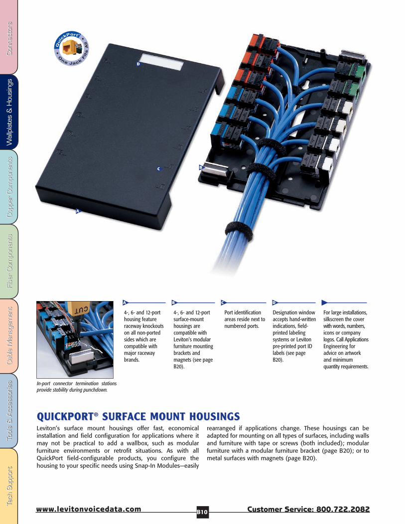
In-port connector termination stationsprovide stability during punchdown.
A
C
D
B
4-, 6- and 12-porthousing featureraceway knockoutson all non-portedsides which arecompatible withmajor racewaybrands.
4-, 6- and 12-portsurface-mounthousings arecompatible withLeviton's modularfurniture mountingbrackets andmagnets (see pageB20).
Port identificationareas reside next tonumbered ports.
Designation windowaccepts hand-writtenindications, field-printed labelingsystems or Levitonpre-printed port IDlabels (see pageB20).
For large installations,silkscreen the coverwith words, numbers,icons or companylogos. Call ApplicationsEngineering foradvice on artworkand minimumquantity requirements.
A B C D
Leviton’s surface mount housings offer fast, economicalinstallation and field configuration for applications where itmay not be practical to add a wallbox, such as modularfurniture environments or retrofit situations. As with allQuickPort field-configurable products, you configure thehousing to your specific needs using Snap-In Modules—easily
rearranged if applications change. These housings can beadapted for mounting on all types of surfaces, including wallsand furniture with tape or screws (both included); modularfurniture with a modular furniture bracket (page B20); or tometal surfaces with magnets (page B20).

T-70
0
Int’l: 425.486.2222 Canada: 800.405.5320
Wallplates &
Housings
Fax: 4
25
.48
3.5
27
0
Int’l Fax: 42
5.4
85
.91
70
C
anada Fax: 80
0.5
63
.18
53
w
ww
.levitonvoicedata.comW
allplates & H
ousings
B11
QUICKPORTQUICKPORT®® 1,1, 2-,2-, 4-,4-, 6- & 12-PORT SURF6- & 12-PORT SURFAACE MOUNT HOUSINGSCE MOUNT HOUSINGS
*=Color choices: Ivory(I), White(W), Grey(G), Black(E) Materials: High-impact fire-retardant plastic rated UL 94V-0.
Note: Snap-In Modules must be ordered separately. (See page A3-A7)
Leviton also offers Pre-configured Voice-Grade Surface Mount Jacks. (See page B18)
B
C
D
A
[A-E] Leviton has a surface mount housing to suit your need.1-, 2-, 4-, 6- and 12-Port housings are easily field configuredwith QuickPort Snap-in Modules (sold separately, page A3-A7). The 2-port version comes with a blank filler to cover andprotect one unused opening. The 4- and 6-port housings aresized to completely cover a single-gang NEMA wallbox open-ing, while the 12-port fits over a single- or dual-gang NEMAbox opening. Housings contain knockouts to accommodateraceway and cable entry, with built-in strain relief to assure
undisturbed connections, and easy cover latches allow foreasy adds, moves and changes.
All housings can be mounted with screws or adhesivemounting tape (both provided), or with magnets or modularfurniture brackets (sold separately on page B20). Identifyports and stations by using ample space next to each port orthe designation window. All housings are UL Listed andcompliant with NEC Article 800.
[A] 1-Port Surface Mount Housing 41089-1*P
[B] 2-Port Surface Mount Housing (includes 1 blank module) 41089-2*P
[C] 4-Port Surface Mount Housing 41089-4*P
[D] 6-Port Surface Mount Housing 41089-6*P
[E] 12-Port Surface Mount Housing 41089-12*
QuickPort® Surface Mount HousingsDescription Part Number
E
Fibe
r Com
pone
nts
Fibe
r Com
pone
nts
Cab
le M
anag
emen
tCab
le M
anag
emen
tTo
ols
& A
cces
sorie
sTo
ols
& A
cces
sorie
sCop
per
Com
pone
nts
Cop
per
Com
pone
nts
Wal
lpla
tes
& H
ousi
ngs
Wal
lpla
tes
& H
ousi
ngs
Con
nect
ors
Con
nect
ors
Tech
Sup
port
Tech
Sup
port
Customer Service: 800.722.2082www.levitonvoicedata.com B12
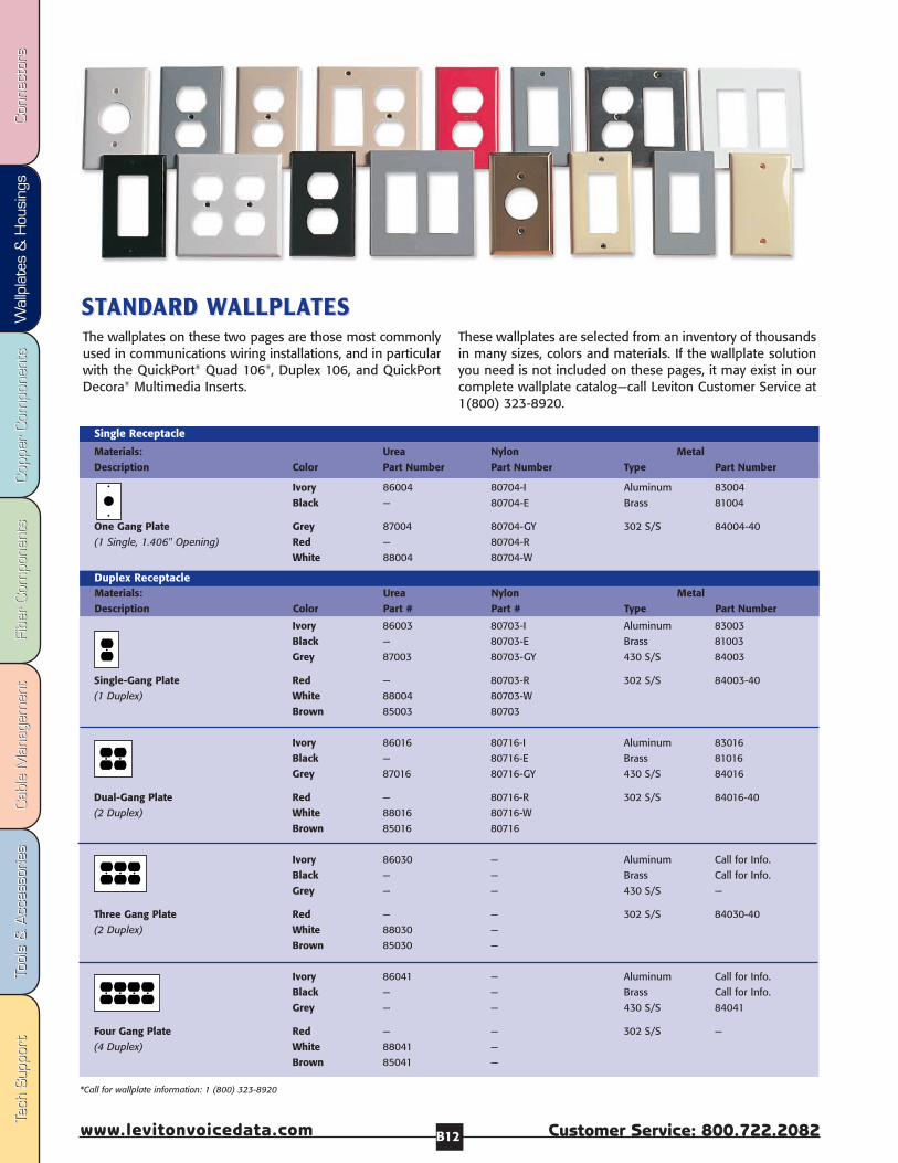
The wallplates on these two pages are those most commonlyused in communications wiring installations, and in particularwith the QuickPort® Quad 106®, Duplex 106, and QuickPortDecora® Multimedia Inserts.
These wallplates are selected from an inventory of thousandsin many sizes, colors and materials. If the wallplate solutionyou need is not included on these pages, it may exist in ourcomplete wallplate catalog—call Leviton Customer Service at1(800) 323-8920.
*Call for wallplate information: 1 (800) 323-8920
Ivory 86003 80703-I Aluminum 83003
Black — 80703-E Brass 81003
Grey 87003 80703-GY 430 S/S 84003
Single-Gang Plate Red — 80703-R 302 S/S 84003-40
(1 Duplex) White 88004 80703-W
Brown 85003 80703
Ivory 86016 80716-I Aluminum 83016
Black — 80716-E Brass 81016
Grey 87016 80716-GY 430 S/S 84016
Dual-Gang Plate Red — 80716-R 302 S/S 84016-40
(2 Duplex) White 88016 80716-W
Brown 85016 80716
Ivory 86030 — Aluminum Call for Info.
Black — — Brass Call for Info.
Grey — — 430 S/S —
Three Gang Plate Red — — 302 S/S 84030-40
(2 Duplex) White 88030 —
Brown 85030 —
Ivory 86041 — Aluminum Call for Info.
Black — — Brass Call for Info.
Grey — — 430 S/S 84041
Four Gang Plate Red — — 302 S/S —
(4 Duplex) White 88041 —
Brown 85041 —
Ivory 86004 80704-I Aluminum 83004
Black — 80704-E Brass 81004
One Gang Plate Grey 87004 80704-GY 302 S/S 84004-40
(1 Single, 1.406" Opening) Red — 80704-R
White 88004 80704-W
Single Receptacle
Materials: Urea Nylon MetalDescription Color Part Number Part Number Type Part Number
Materials: Urea Nylon MetalDescription Color Part # Part # Type Part Number
Duplex Receptacle
STSTANDANDARD ARD WWALLPLAALLPLATESTES

T-70
0
Int’l: 425.486.2222 Canada: 800.405.5320
Wallplates &
Housings
Fax: 4
25
.48
3.5
27
0
Int’l Fax: 42
5.4
85
.91
70
C
anada Fax: 80
0.5
63
.18
53
w
ww
.levitonvoicedata.comW
allplates & H
ousings
B13
Ivory 80401-I 80401-NI 80301-I Aluminum 83401Black 80401-E — 80301-E Brass 81401Grey 80401-GY 80401-NGY 80301-GY Polish. Brass 81401-PBRed — 80401-NR 80301-R 302 S/S° 84401-40
Single-Gang Plate White 80401-W 80401-NW 80301-W 430 S/S° —(1 Decora) Brown 80401 80401-N 80301
Almond 80401-A — 80301-A
Ivory 80409-I 80409-NI 80309-I Aluminum 83409Black 80409-E — 80309-E Brass 81409Grey 80409-GY 80409-NGY 80309-GY Polish. Brass 81409-PBRed — 80409-NR 80309-R 302 S/S° 84409-40
Dual-Gang Plate White 80409-W 80409-NW 80309-W 430 S/S° —(2 Decora) Brown 80409 80409-N 80309
Almond 80409-A — 80309-A
Ivory 80411-I 80411-NI 80311-I Aluminum 83411Black 80411-E — 80311-E Brass 81411Grey 80411-GY 80401-NGY 80311-GY Polish. Brass 81411-PBRed — 80401-NR 80311-R 302 S/S° 84411-40
Three Gang Plate White 80411-W 80401-NW 80311-W 430 S/S° —(3 Decora) Brown 80411 80401-N 80311
Almond 80411-A — 80311-A
Ivory 80412-I 80412-NI 80312-I Aluminum —Black 80412-E — 80312-E Brass —Grey 80412-GY — 80312-GY 430 S/S° —Red 80412-R — 80312-R 302 S/S° 84412-40
Four Gang Plate White 80412-W 80401-NW 80312-W(4 Decora) Brown 80412 — 80312
Almond 80412-A — 80312-A
Decora/GFCI Fits all Decora Devices and GFCIsMaterials: Urea Nylon Decora Plus® MetalDescription Color Part # Part # Snap-On Type Part #
Ivory 80455-I — Aluminum –Black – – Brass –
Dual-Gang Plate White 80455-W — 430 S/S° –(1 Duplex, Brown 80455 — 302 S/S° 84455-401 Decora/GFCI) Almond 80455-A — – –
Dual-Gang Plate Ivory 86008 N138-I – –(1 Duplex, 1 Blank, White 88008 N138-W – –Box Mount) Brown 85008 — – –
Single-Gang Blank Ivory 86014 80714-I Aluminum –(1 Duplex, 1 Blank, White 88014 80714-W Brass –Box Mount) Grey 87014 80714-GY 302 S/S° 84014-40
Dual-Gang Blank Ivory 86025 80725-I – –(2 -Gang, 2 Blanks, White 88025 80725-W – –Box Mount) Grey 87025 80725-GY – –
Ivory — N751-I 302 S/S S751-N
White — N751-W – –
Split Plate (.406 round hole)
Materials: Urea Nylon MetalDescription Color Part # Part # Type Part #
Standard Combinations, Blank Plates, Split Plates
*Call for weather resistant covers, midsized wallplates, and oversized wallplates: 1(800) 323-8920
° 302 S/S = non-magnetic, 430 S/S = magnetic
You can count onLeviton wallplates forquality and durability:
• Listed by UnderwritersLaboratories, Inc.
• Certified by Canadian StandardsAssociation.
• Meet current FederalSpecifications as tested to UL 514.
• Conforms to NEMA and ANSIStandards.
• Non-combustible.
• Easily cleaned.
• Supplied with metal mountingscrews matched to plate color.
• Individually wrapped, with mount-ing screws enclosed in an internalenvelope to prevent scratchingthe plate.
• Configurations available instandard, mid-way, oversize,and extra deep dimensions.
• Premium Industrial SpecificationGrade and CommercialSpecification Grade 10-YearWarranty where applicable.
Fibe
r Com
pone
nts
Fibe
r Com
pone
nts
Cab
le M
anag
emen
tCab
le M
anag
emen
tTo
ols
& A
cces
sorie
sTo
ols
& A
cces
sorie
sCop
per
Com
pone
nts
Cop
per
Com
pone
nts
Wal
lpla
tes
& H
ousi
ngs
Wal
lpla
tes
& H
ousi
ngs
Con
nect
ors
Con
nect
ors
Tech
Sup
port
Tech
Sup
port
Customer Service: 800.722.2082www.levitonvoicedata.com B14
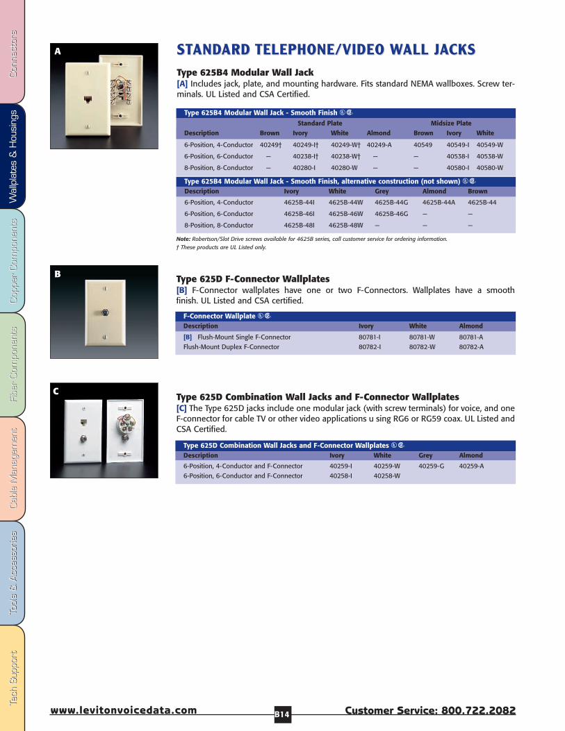
STSTANDANDARD ARD TELEPHONE/VIDEO TELEPHONE/VIDEO WWALL JALL JAACKSCKSType 625B4 Modular Wall Jack[A] Includes jack, plate, and mounting hardware. Fits standard NEMA wallboxes. Screw ter-minals. UL Listed and CSA Certified.
6-Position, 4-Conductor 40249† 40249-I† 40249-W† 40249-A 40549 40549-I 40549-W
6-Position, 6-Conductor — 40238-I† 40238-W† — — 40538-I 40538-W
8-Position, 8-Conductor — 40280-I 40280-W — — 40580-I 40580-W
Type 625B4 Modular Wall Jack - Smooth Finish USStandard Plate Midsize Plate
Description Brown Ivory White Almond Brown Ivory White
6-Position, 4-Conductor 4625B-44I 4625B-44W 4625B-44G 4625B-44A 4625B-44
6-Position, 6-Conductor 4625B-46I 4625B-46W 4625B-46G — —
8-Position, 8-Conductor 4625B-48I 4625B-48W — — —
Type 625B4 Modular Wall Jack - Smooth Finish, alternative construction (not shown) USDescription Ivory White Grey Almond Brown
A
[B] Flush-Mount Single F-Connector 80781-I 80781-W 80781-A
Flush-Mount Duplex F-Connector 80782-I 80782-W 80782-A
F-Connector Wallplate USDescription Ivory White Almond
B
Type 625D Combination Wall Jacks and F-Connector Wallplates[C] The Type 625D jacks include one modular jack (with screw terminals) for voice, and oneF-connector for cable TV or other video applications u sing RG6 or RG59 coax. UL Listed andCSA Certified.
C
6-Position, 4-Conductor and F-Connector 40259-I 40259-W 40259-G 40259-A
6-Position, 6-Conductor and F-Connector 40258-I 40258-W
Type 625D Combination Wall Jacks and F-Connector Wallplates USDescription Ivory White Grey Almond
Type 625D F-Connector Wallplates[B] F-Connector wallplates have one or two F-Connectors. Wallplates have a smooth finish. UL Listed and CSA certified.
Note: Robertson/Slot Drive screws available for 4625B series, call customer service for ordering information.† These products are UL Listed only.

T-70
0
Int’l: 425.486.2222 Canada: 800.405.5320
Wallplates &
Housings
Fax: 4
25
.48
3.5
27
0
Int’l Fax: 42
5.4
85
.91
70
C
anada Fax: 80
0.5
63
.18
53
w
ww
.levitonvoicedata.comW
allplates & H
ousings
B15
Midsize Wall Jacks[D] Midsize wall jacks provide a larger silhouette for a more designer look, and to easily hideirregular drywall cuts. Choose a voice grade connector for UTP cable or an F-connector (filledor empty) for coaxial cable. Crafted from durable, UV-resistant nylon.
Midsize Video Wallplate with F-Connector 40539-0M*
Midsize Video Wallplate without F-Connector (hexagonal opening only) 40539-HM*
Midsize Phone Wallplate with 6P4C Voice Grade Connector 40539-PM*
QuickPort Midsize WallplatesDescription Part Number
*= Color: (I)Ivory, (W)White, (A)Almond, (B)Brown
Type 625B3 Midsize Duplex Wall JackThese smooth finish midsize units include 2 jacks, wallplate and mounting hardward. Wireto provide the same dialtone on both jacks or separate lines. Screw terminals. UL Listed &CSA Certified.
Type 625B3 Duplex Wall Jack, 6-position 4-conductor, Midsize Plate 40544-I 40544-W
Type 625B3 Duplex Wall Jack, 6-position 6-conductor, Midsize Plate 40566-I 40566-W
Type 625B3 Duplex Wall Jack, 8-position 8-conductor, Midsize Plate 40588-I 40588-W
Type 625B3 Duplex Wall JackDescription Ivory White
MIDSIZE MIDSIZE TELEPHONE TELEPHONE WWALL JALL JAACKSCKS
D
Decora TV/Phone Combination Jack[C] Combination jack with 4-Conductor modular jack for UTP telephone connections and F-Connector for video (coaxial cable) connections. Includes matching Decora wallplate.
Decora TV/Phone Combination Jack, 6-position 4-conductor 40959-ID 40959-WD
Decora TV/Phone Combination JackDescription Ivory White
Type 625 Decora Modular Wall Jacks[B] Single flush mount jack for use with Decora or Decora Plus wallplates. Mount in stan-dard or multi-gang electrical box. Screw terminals. UL Listed and CSA Certified.
6-position 4-conductor 40649-I 40649-W 40649-GY 40649 40649-A 40649-E
6-position 6-conductor 40638-I 40638-W 40638-GY 40638 -- --
8-position 8-conductor 40680-I 40680-W 40680-GY 40680 -- --
Type 625 Decora Modular Wall JackDescription Ivory White Grey Brown Almond Black
C
Decora Modular Single or Duplex Wall Jack Inserts[A] These single or duplex flush-mount voice-grade connectors fit in Leviton’s popularDecora line of devices. Screw terminals. Includes matching Decora wallplate.
Decora Single Modular Wall Jack, 6-position 4-conductor 40949-ID 40949-WD
Decora Duplex Modular Wall Jack, 6-position 4-conductor 40944-ID 40944-WD
Decora Modular Wall JackDescription Ivory White
DECORA DECORA TELEPHONE TELEPHONE WWALL JALL JAACK INSERTSCK INSERTS A
B
Fibe
r Com
pone
nts
Fibe
r Com
pone
nts
Cab
le M
anag
emen
tCab
le M
anag
emen
tTo
ols
& A
cces
sorie
sTo
ols
& A
cces
sorie
sCop
per
Com
pone
nts
Cop
per
Com
pone
nts
Wal
lpla
tes
& H
ousi
ngs
Wal
lpla
tes
& H
ousi
ngs
Con
nect
ors
Con
nect
ors
Tech
Sup
port
Tech
Sup
port
Customer Service: 800.722.2082www.levitonvoicedata.com B16
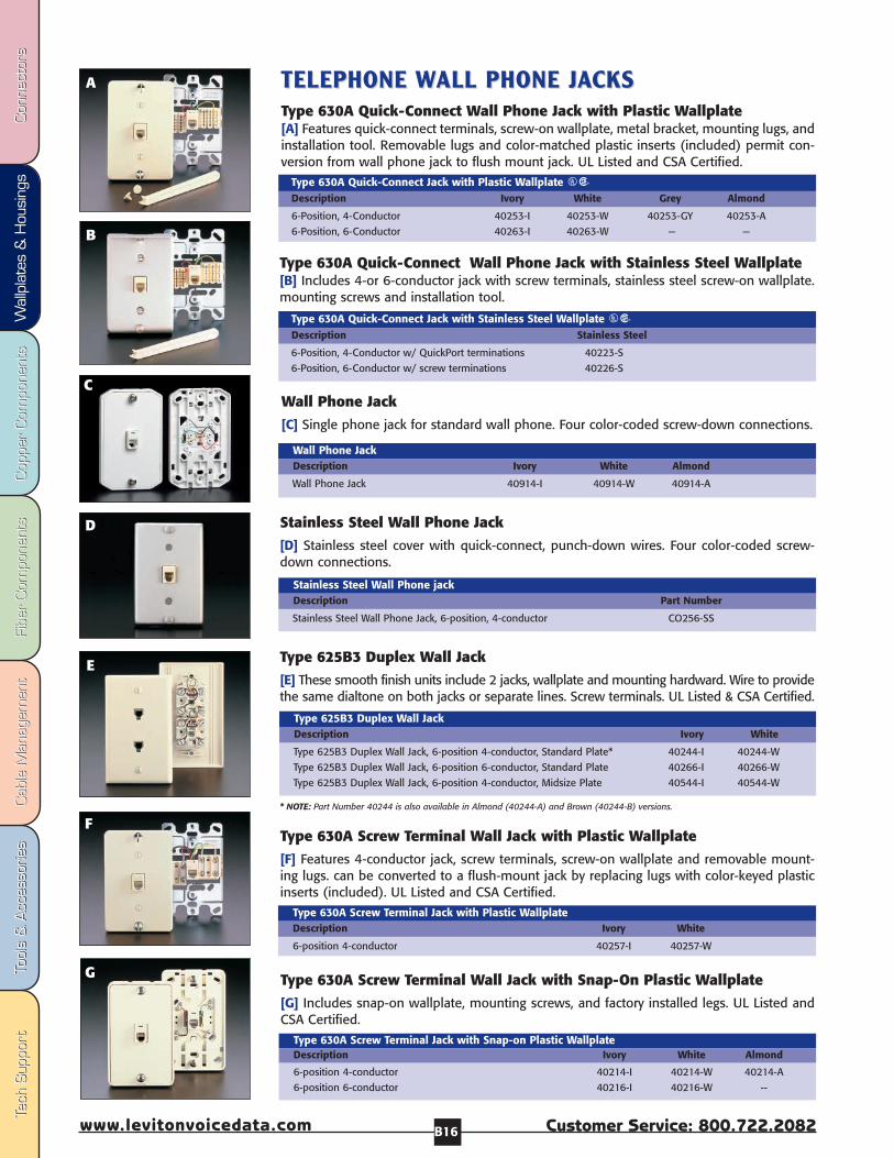
A TELEPHONE TELEPHONE WWALL PHONE JALL PHONE JAACKS CKS Type 630A Quick-Connect Wall Phone Jack with Plastic Wallplate [A] Features quick-connect terminals, screw-on wallplate, metal bracket, mounting lugs, andinstallation tool. Removable lugs and color-matched plastic inserts (included) permit con-version from wall phone jack to flush mount jack. UL Listed and CSA Certified.
6-Position, 4-Conductor 40253-I 40253-W 40253-GY 40253-A
6-Position, 6-Conductor 40263-I 40263-W — —
Type 630A Quick-Connect Jack with Plastic Wallplate USDescription Ivory White Grey Almond
6-Position, 4-Conductor w/ QuickPort terminations 40223-S
6-Position, 6-Conductor w/ screw terminations 40226-S
Type 630A Quick-Connect Jack with Stainless Steel Wallplate USDescription Stainless Steel
B
Stainless Steel Wall Phone Jack[D] Stainless steel cover with quick-connect, punch-down wires. Four color-coded screw-down connections.
Stainless Steel Wall Phone Jack, 6-position, 4-conductor CO256-SS
Stainless Steel Wall Phone jackDescription Part Number
Wall Phone Jack [C] Single phone jack for standard wall phone. Four color-coded screw-down connections.
Wall Phone Jack 40914-I 40914-W 40914-A
Wall Phone JackDescription Ivory White Almond
C
D
Type 630A Quick-Connect Wall Phone Jack with Stainless Steel Wallplate [B] Includes 4-or 6-conductor jack with screw terminals, stainless steel screw-on wallplate.mounting screws and installation tool.
Type 625B3 Duplex Wall Jack[E] These smooth finish units include 2 jacks, wallplate and mounting hardward. Wire to providethe same dialtone on both jacks or separate lines. Screw terminals. UL Listed & CSA Certified.
Type 625B3 Duplex Wall Jack, 6-position 4-conductor, Standard Plate* 40244-I 40244-W
Type 625B3 Duplex Wall Jack, 6-position 6-conductor, Standard Plate 40266-I 40266-W
Type 625B3 Duplex Wall Jack, 6-position 4-conductor, Midsize Plate 40544-I 40544-W
Type 625B3 Duplex Wall JackDescription Ivory White
F
E
Type 630A Screw Terminal Wall Jack with Plastic Wallplate[F] Features 4-conductor jack, screw terminals, screw-on wallplate and removable mount-ing lugs. can be converted to a flush-mount jack by replacing lugs with color-keyed plasticinserts (included). UL Listed and CSA Certified.
6-position 4-conductor 40257-I 40257-W
Type 630A Screw Terminal Jack with Plastic WallplateDescription Ivory White
Type 630A Screw Terminal Wall Jack with Snap-On Plastic Wallplate[G] Includes snap-on wallplate, mounting screws, and factory installed legs. UL Listed andCSA Certified.
6-position 4-conductor 40214-I 40214-W 40214-A
6-position 6-conductor 40216-I 40216-W --
Type 630A Screw Terminal Jack with Snap-on Plastic WallplateDescription Ivory White Almond
G
* NOTE: Part Number 40244 is also available in Almond (40244-A) and Brown (40244-B) versions.
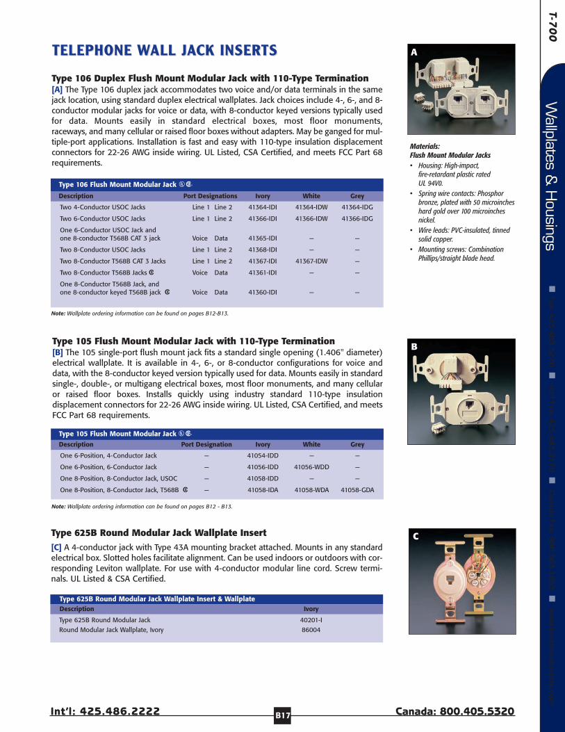
T-70
0
Int’l: 425.486.2222 Canada: 800.405.5320
Wallplates &
Housings
Fax: 4
25
.48
3.5
27
0
Int’l Fax: 42
5.4
85
.91
70
C
anada Fax: 80
0.5
63
.18
53
w
ww
.levitonvoicedata.comW
allplates & H
ousings
B17
A
Materials: Flush Mount Modular Jacks• Housing: High-impact,
fire-retardant plastic ratedUL 94V0.
• Spring wire contacts: Phosphorbronze, plated with 50 microincheshard gold over 100 microinchesnickel.
• Wire leads: PVC-insulated, tinnedsolid copper.
• Mounting screws: CombinationPhillips/straight blade head.
B
Type 106 Duplex Flush Mount Modular Jack with 110-Type Termination[A] The Type 106 duplex jack accommodates two voice and/or data terminals in the samejack location, using standard duplex electrical wallplates. Jack choices include 4-, 6-, and 8-conductor modular jacks for voice or data, with 8-conductor keyed versions typically usedfor data. Mounts easily in standard electrical boxes, most floor monuments,raceways, and many cellular or raised floor boxes without adapters. May be ganged for mul-tiple-port applications. Installation is fast and easy with 110-type insulation displacementconnectors for 22-26 AWG inside wiring. UL Listed, CSA Certified, and meets FCC Part 68requirements.
One 6-Position, 4-Conductor Jack — 41054-IDD — —
One 6-Position, 6-Conductor Jack — 41056-IDD 41056-WDD —
One 8-Position, 8-Conductor Jack, USOC — 41058-IDD — —
One 8-Position, 8-Conductor Jack, T568B 3 — 41058-IDA 41058-WDA 41058-GDA
Type 105 Flush Mount Modular Jack USDescription Port Designation Ivory White Grey
Note: Wallplate ordering information can be found on pages B12 - B13.
Type 105 Flush Mount Modular Jack with 110-Type Termination [B] The 105 single-port flush mount jack fits a standard single opening (1.406" diameter)electrical wallplate. It is available in 4-, 6-, or 8-conductor configurations for voice anddata, with the 8-conductor keyed version typically used for data. Mounts easily in standardsingle-, double-, or multigang electrical boxes, most floor monuments, and many cellularor raised floor boxes. Installs quickly using industry standard 110-type insulationdisplacement connectors for 22-26 AWG inside wiring. UL Listed, CSA Certified, and meetsFCC Part 68 requirements.
TELEPHONE TELEPHONE WWALL JALL JAACK INSERTSCK INSERTS
Type 625B Round Modular Jack Wallplate Insert[C] A 4-conductor jack with Type 43A mounting bracket attached. Mounts in any standardelectrical box. Slotted holes facilitate alignment. Can be used indoors or outdoors with cor-responding Leviton wallplate. For use with 4-conductor modular line cord. Screw termi-nals. UL Listed & CSA Certified.
Type 625B Round Modular Jack 40201-I
Round Modular Jack Wallplate, Ivory 86004
Type 625B Round Modular Jack Wallplate Insert & WallplateDescription Ivory
Note: Wallplate ordering information can be found on pages B12-B13.
C
Two 4-Conductor USOC Jacks Line 1 Line 2 41364-IDI 41364-IDW 41364-IDG
Two 6-Conductor USOC Jacks Line 1 Line 2 41366-IDI 41366-IDW 41366-IDG
One 6-Conductor USOC Jack and one 8-conductor T568B CAT 3 jack Voice Data 41365-IDI — —
Two 8-Conductor USOC Jacks Line 1 Line 2 41368-IDI — —
Two 8-Conductor T568B CAT 3 Jacks Line 1 Line 2 41367-IDI 41367-IDW —
Two 8-Conductor T568B Jacks 3 Voice Data 41361-IDI — —
One 8-Conductor T568B Jack, and one 8-conductor keyed T568B jack 3 Voice Data 41360-IDI — —
Type 106 Flush Mount Modular Jack US
Description Port Designations Ivory White Grey
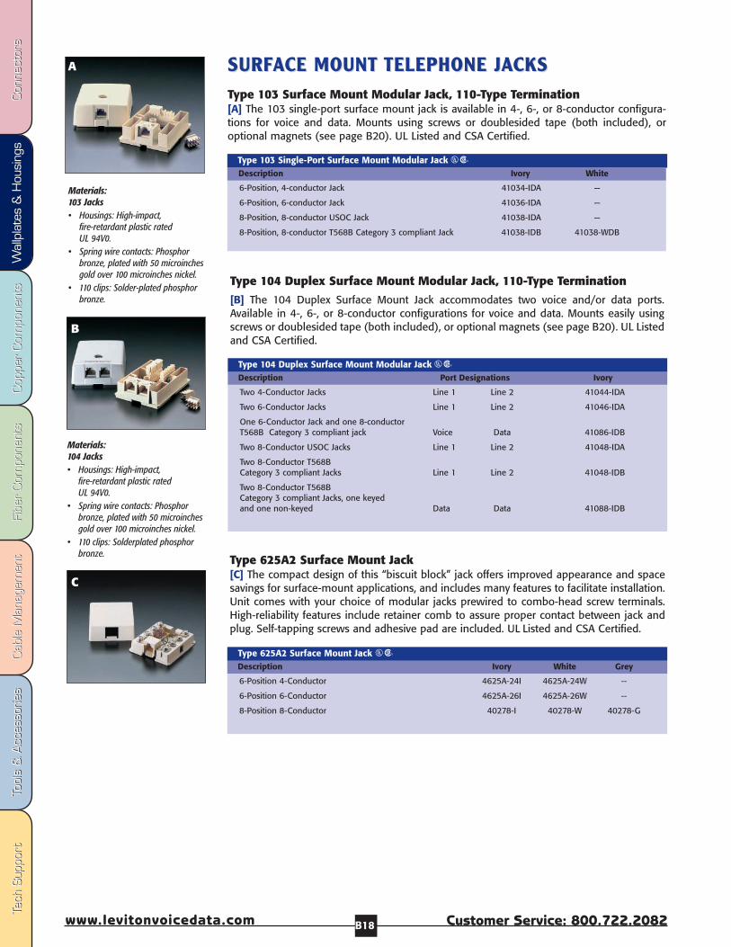
Fibe
r Com
pone
nts
Fibe
r Com
pone
nts
Cab
le M
anag
emen
tCab
le M
anag
emen
tTo
ols
& A
cces
sorie
sTo
ols
& A
cces
sorie
sCop
per
Com
pone
nts
Cop
per
Com
pone
nts
Wal
lpla
tes
& H
ousi
ngs
Wal
lpla
tes
& H
ousi
ngs
Con
nect
ors
Con
nect
ors
Tech
Sup
port
Tech
Sup
port
Customer Service: 800.722.2082www.levitonvoicedata.com B18
C
6-Position, 4-conductor Jack 41034-IDA —
6-Position, 6-conductor Jack 41036-IDA —
8-Position, 8-conductor USOC Jack 41038-IDA —
8-Position, 8-conductor T568B Category 3 compliant Jack 41038-IDB 41038-WDB
Type 103 Single-Port Surface Mount Modular Jack USDescription Ivory White
SURFSURFAACE MOUNT CE MOUNT TELEPHONE JTELEPHONE JAACKSCKSType 103 Surface Mount Modular Jack, 110-Type Termination [A] The 103 single-port surface mount jack is available in 4-, 6-, or 8-conductor configura-tions for voice and data. Mounts using screws or doublesided tape (both included), oroptional magnets (see page B20). UL Listed and CSA Certified.
Type 104 Duplex Surface Mount Modular Jack, 110-Type Termination[B] The 104 Duplex Surface Mount Jack accommodates two voice and/or data ports.Available in 4-, 6-, or 8-conductor configurations for voice and data. Mounts easily usingscrews or doublesided tape (both included), or optional magnets (see page B20). UL Listedand CSA Certified.
Two 4-Conductor Jacks Line 1 Line 2 41044-IDA
Two 6-Conductor Jacks Line 1 Line 2 41046-IDA
One 6-Conductor Jack and one 8-conductorT568B Category 3 compliant jack Voice Data 41086-IDB
Two 8-Conductor USOC Jacks Line 1 Line 2 41048-IDA
Two 8-Conductor T568B Category 3 compliant Jacks Line 1 Line 2 41048-IDB
Two 8-Conductor T568B Category 3 compliant Jacks, one keyedand one non-keyed Data Data 41088-IDB
Type 104 Duplex Surface Mount Modular Jack USDescription Port Designations Ivory
Type 625A2 Surface Mount Jack [C] The compact design of this “biscuit block” jack offers improved appearance and spacesavings for surface-mount applications, and includes many features to facilitate installation.Unit comes with your choice of modular jacks prewired to combo-head screw terminals.High-reliability features include retainer comb to assure proper contact between jack andplug. Self-tapping screws and adhesive pad are included. UL Listed and CSA Certified.
6-Position 4-Conductor 4625A-24I 4625A-24W --
6-Position 6-Conductor 4625A-26I 4625A-26W --
8-Position 8-Conductor 40278-I 40278-W 40278-G
Type 625A2 Surface Mount Jack USDescription Ivory White Grey
Materials:104 Jacks• Housings: High-impact,
fire-retardant plastic ratedUL 94V0.
• Spring wire contacts: Phosphorbronze, plated with 50 microinchesgold over 100 microinches nickel.
• 110 clips: Solderplated phosphorbronze.
B
Materials:103 Jacks• Housings: High-impact,
fire-retardant plastic ratedUL 94V0.
• Spring wire contacts: Phosphorbronze, plated with 50 microinchesgold over 100 microinches nickel.
• 110 clips: Solder-plated phosphorbronze.
A
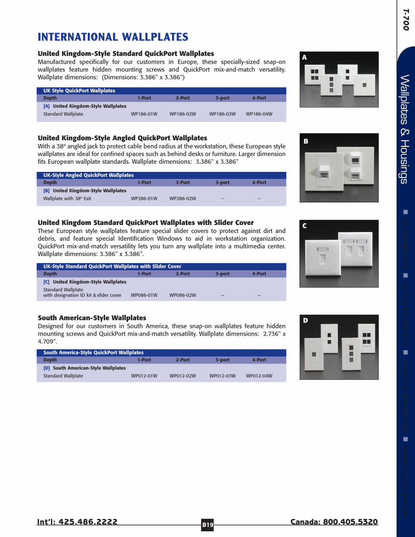
T-70
0
Int’l: 425.486.2222 Canada: 800.405.5320
Wallplates &
Housings
Fax: 4
25
.48
3.5
27
0
Int’l Fax: 42
5.4
85
.91
70
C
anada Fax: 80
0.5
63
.18
53
w
ww
.levitonvoicedata.comW
allplates & H
ousings
B19
B
INTERNAINTERNATIONAL TIONAL WWALLPLAALLPLATESTESUnited Kingdom-Style Standard QuickPort WallplatesManufactured specifically for our customers in Europe, these specially-sized snap-onwallplates feature hidden mounting screws and QuickPort mix-and-match versatility.Wallplate dimensions: (Dimensions: 3.386" x 3.386")
[A] United Kingdom-Style Wallplates
Standard Wallplate WP186-01W WP186-02W WP186-03W WP186-04W
UK Style QuickPort WallplatesDepth 1-Port 2-Port 3-port 4-Port
South American-Style WallplatesDesigned for our customers in South America, these snap-on wallplates feature hiddenmounting screws and QuickPort mix-and-match versatility. Wallplate dimensions: 2.736" x4.709".
[D] South American-Style Wallplates
Standard Wallplate WP012-01W WP012-02W WP012-03W WP012-04W
South America-Style QuickPort WallplatesDepth 1-Port 2-Port 3-port 4-Port
United Kingdom Standard QuickPort Wallplates with Slider CoverThese European style wallplates feature special slider covers to protect against dirt anddebris, and feature special Identification Windows to aid in workstation organization.QuickPort mix-and-match versatility lets you turn any wallplate into a multimedia center.Wallplate dimensions: 3.386" x 3.386".
[C] United Kingdom-Style Wallplates
Standard Wallplate with designation ID kit & slider cover WP086-01W WP086-02W -- --
UK-Style Standard QuickPort Wallplates with Slider CoverDepth 1-Port 2-Port 3-port 4-Port
United Kingdom-Style Angled QuickPort WallplatesWith a 38º angled jack to protect cable bend radius at the workstation, these European stylewallplates are ideal for confined spaces such as behind desks or furniture. Larger dimensionfits European wallplate standards. Wallplate dimensions: 3.386" x 3.386"
[B] United Kingdom-Style Wallplates
Wallplate with 38º Exit WP286-01W WP286-02W -- --
UK-Style Angled QuickPort WallplatesDepth 1-Port 2-Port 3-port 4-Port
C
D
A
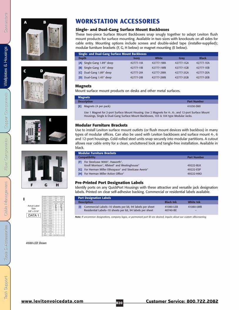
Fibe
r Com
pone
nts
Fibe
r Com
pone
nts
Cab
le M
anag
emen
tCab
le M
anag
emen
tTo
ols
& A
cces
sorie
sTo
ols
& A
cces
sorie
sCop
per
Com
pone
nts
Cop
per
Com
pone
nts
Wal
lpla
tes
& H
ousi
ngs
Wal
lpla
tes
& H
ousi
ngs
Con
nect
ors
Con
nect
ors
Tech
Sup
port
Tech
Sup
port
Customer Service: 800.722.2082www.levitonvoicedata.com B20
WWORKSTORKSTAATION TION AACCESSORIESCCESSORIESSingle- and Dual-Gang Surface Mount BackboxesThese two-piece Surface Mount Backboxes snap snugly together to adapt Leviton flushmount products for surface mounting. Available in two sizes with knockouts on all sides forcable entry. Mounting options include screws and double-sided tape (installer-supplied);modular furniture brackets (F, G, H below) or magnet mounting (E below).
A
C
E
F
Note: If uncommon designations, company logos, or permanent port ID are desired, inquire about our custom silkscreening.
[F] For Steelcase 9000®, Haworth®, Knoll Morrison®, Allsteel® and Westinghouse® 49222-BLK
[G] For Herman Miller Ethospace® and Steelcase Avenir® 49222-ESP
[H] For Herman Miller Action Office® 49222-HAO
Modular Furniture BracketsCompatibility Part Number
[A] Single-Gang 1.89" deep 42777-1IA 42777-1WA 42777-1GA 42777-1EA
[B] Single-Gang 1.45" deep 42777-1IB 42777-1WB 42777-1GB 42777-1EB
[C] Dual-Gang 1.89" deep 42777-2IA 42777-2WA 42777-2GA 42777-2EA
[D] Dual-Gang 1.45" deep 42777-2IB 42777-2WB 42777-2GB 42777-2EB
Single- and Dual-Gang Surface Mount BackboxesDepth Ivory White Grey Black
[E] Magnets (4 per pack) 41030-SMJ
Use 1 Magnet for 2-port Surface Mount Housing. Use 2 Magnets for 4-, 6-, and 12-port Surface MountHousings, Single & Dual-Gang Surface Mount Backboxes, 103 & 104 type Modular Jacks.
MagnetsDescription Part Number
[I] Commercial Labels–10 sheets per kit, 94 labels per sheet 41080-LEB 41080-LWBResidential Labels–10 sheets per kit, 94 labels per sheet 40740-BE –
Port Designation LabelsDescription Black Ink White Ink
G H
B
D
41080-LEB Shown
I
Pre-Printed Port Designation LabelsIdentify ports on any QuickPort Housings with these attractive and versatile jack designationlabels. Printed on clear self-adhesive backing. Commercial or residential labels available.
Modular Furniture Brackets Use to install Leviton surface mount outlets (or flush mount devices with backbox) in manytypes of modular offices. Can also be used with Leviton backboxes and surface mount 4-, 6and 12-port housings. Cold-rolled steel units snap securely into modular partitions. A cutoutallows rear cable entry for a clean, uncluttered look and tangle-free installation. Available inblack.
MagnetsMount surface mount products on desks and other metal surfaces.

Universal Category 6 Panels & Blocks C3
Universal Category 5 & 5e Panels & Blocks C4
Voice-Grade Patch Panels C5
Modular Angled Patch Panels C6
QuickPort® Multimedia Panels & Blocks C7
Rack-Mount Surge Protection C8
Performance Patch Cords C9
Rack & Panel Accessories C9
110 Wiring Products C10
66-Clip Connecting Blocks/Accessories C14
Surface-Mount Mini Patch Panels C16

Fibe
r Com
pone
nts
Fibe
r Com
pone
nts
Cab
le M
anag
emen
tCab
le M
anag
emen
tTo
ols
& A
cces
sorie
sTo
ols
& A
cces
sorie
sCop
per
Com
pone
nts
Cop
per
Com
pone
nts
Wal
lpla
tes
& H
ousi
ngs
Wal
lpla
tes
& H
ousi
ngs
Con
nect
ors
Con
nect
ors
Tech
Sup
port
Tech
Sup
port
Customer Service: 800.722.2082www.levitonvoicedata.com C2
Related Products
QUICKPORT UTPQUICKPORT UTP COPPERCOPPERCONNECTCONNECTORSORS
High performance Category 6, 5e, 5 and 3 connectors, in 13 colors,
as well as Voice Grade, and a selection of accessories (Page A3).
QUICKPORT QUICKPORT AAUDIO/VIDEO MODULESUDIO/VIDEO MODULES
Connectors and adapters for audio andvideo over coaxial cable, speaker wire
and UTP copper (Page A4).
FIBER OPTIC CONNECTFIBER OPTIC CONNECTORS ORS ANDANDQUICKPORT QUICKPORT ADADAPTERSAPTERS
Innovative, craft-friendly ST, SC, FC, MT-RJand LC connectors, in mechanical or
epoxy styles. Plus adapters to fit them to any QuickPort housing (Page A6).
QUICKPORT SHUTTERS & ICONSQUICKPORT SHUTTERS & ICONSField-installable QuickPort Shutters with
icons protect connectors from dust &debris, and feature labels and recessed
windows for port identification (Page A8).
Copper ComponentsDiscover Leviton’s broad variety of solutions for Copper distribution. Leviton offershigh-performance Category 6, Category 5e and Category 5 Universal Patch Panels,pre-configured with craft-friendly 110 punchdowns, as well as a Category 6 ModularPanel, Voice Grade Panels, QuickPort field-configurable panels, and the uniqueAngled Panel, in 6+, 5e and QuickPort styles. Additionally, in this section findPatch Cords, accessories and an array of rack-mounted solutions for Surge andPower Quality.
VERSI-DUCT SLOVERSI-DUCT SLOTTED DUCT SYTTED DUCT SYSTEMSTEMVersatile vertical and horizontal rack cable
management system with an array ofinnovative accessories (Page E3).
SPSPAACEMAKERCEMAKERFront-side cable manager saves up to 80%
installation labor time and uses up no rack space (Page E5).
HOOK &HOOK & LOOP CLOOP CABLE MANAABLE MANAGEMENTGEMENTRe-usable Hook and Loop solutions to
protect cables and keep work and closet areas neat (Page E8).
DIADIAGRAMS &GRAMS & INSTRUCTIONSINSTRUCTIONSIn our appendix, find step-by-steptermination instructions, as well as
dimensional diagrams for panels andaccessories (Section X).

T-70
0
Int’l: 425.486.2222 Canada: 800.405.5320
Copper C
omponents
Fax: 4
25
.48
3.5
27
0
Int’l Fax: 42
5.4
85
.91
70
C
anada Fax: 80
0.5
63
.18
53
w
ww
.levitonvoicedata.comCopper C
omponents
C3
EXTREMEEXTREME™™ 6+ UNIVERSAL P6+ UNIVERSAL PAATCH PTCH PANELS ANELS Craft-friendly eXtreme 6+ Universal Patch Panels exceedpublished Category 6 standards and feature patented RetentionForce Technology™ for robust long-term performance andmechanical integrity.
These 12-, 24-, 48 and 96-port panels (and 12-port patchblock) come pre-configured with craft-friendly 110-stylepunchdowns on the rear and six-port RJ-45 front modules.Rear designation labels are reversible, with color-codedwiring diagrams for T568A or T568B configurations.
Additionally, 12-, 24-, 48- and 96 Port panels featureadvanced cable management and grounding stand-offs,come with a cable management bar for proper bend radiusprotection, and accommodate top, bottom or side cableentry.
All eXtreme 6+ panels and blocks mount in standard 19"equipment racks, are cULus Listed, and fully comply withpublished Category 6 standards.
High-density, Pre-Configured Patch Panel with wire management bar 69586-U89 69586-U12 69586-U24 69586-U48 69586-U96
Dimensions: 10.0" H x 2.30" W 1.75” H x 19.0” W 1.75” H x 19.0” W 3.5” H x 19.0” W 7” H x 19.0” W
eXtreme 6+ Universal Patch Panels Description 12-Port 12-Port 24-Port 48-Port 96-Port
Patch Block Panel Panel Panel Panel
Cable management bar andstand-offs facilitate dressingand organizing the cable,and helps maintainoptimum bend radii.
Universal printed circuit-boardmodules— with 110 connections andrear termination field for easy-fieldconfigurability— can be used for T568A,T568B or 25-pair wiring schemes.
Patch panellabeling kit featurescolored slide-infront portidentification labels.
Reversible rear label slideseasily into redesigned slotand shows color-codeddiagrams for T568A, T568Band 25-pair wiring.
UNIVERSAL
T568A &
T568B!
12-Port 24-Port 48-Port 96-Port

Fibe
r Com
pone
nts
Fibe
r Com
pone
nts
Cab
le M
anag
emen
tCab
le M
anag
emen
tTo
ols
& A
cces
sorie
sTo
ols
& A
cces
sorie
sCop
per
Com
pone
nts
Cop
per
Com
pone
nts
Wal
lpla
tes
& H
ousi
ngs
Wal
lpla
tes
& H
ousi
ngs
Con
nect
ors
Con
nect
ors
Tech
Sup
port
Tech
Sup
port
Customer Service: 800.722.2082www.levitonvoicedata.com C4
CCAATEGORTEGORY 5 & GIGAMAXY 5 & GIGAMAX™™ 55ee UNIVERSALUNIVERSALPPAATCH PTCH PANELS & PANELS & PAATCH BLOCKSTCH BLOCKS
Universal Category 5 Patch Panels URDescription 12-Port 16-Port 24-Port 24-Port w/Bar 32-Port 48-Port 64-Port 96-Port
Connector spring wirecontacts are highestquality phosphorbronze, plated with 50microinches gold over100 microinches ofnickel.
Universal printed circuit-board moduleswith 110 IDC punch-downs can be usedfor T568A, T568B and25-pair wiring configu-rations.
Writable/erasable surfacesand numbered jack portshelp identify port assign-ments.
Universal Category 5 and GigaMax 5e PatchPanels and Patch Blocks come in a variety ofport densities to meet the needs of high-speed data applications. Both the blocksand panels come pre-configured with 110-punchdowns on the back and eitherCategory 5 or GigaMax 5e six-port modules,on the front. Ideal for enhancedapplications, both versions can be used forT568A or T568B wiring configurations. Thepanels, available with 12 to 96 pre-
configured ports, mount in standard 19" TIAequipment racks and accommodate top,bottom or side cable entry. For smaller, wall-mount installations, the 12-port patchblocks are an ideal low-profile solution.
GigaMax 5e panels are rated for bothcomponent and channel-level performance.
All panels and blocks are UL Listed and fullycomply with with the latest published TIAguidelines.
T568B/T568A 59484-U12 59484-U16 59484-U24 59484-24U 59484-U32 59484-U48 59484-U64 59484-U96
Dimensions: 1.75" H x 19.0" W 1.75" H x 19.0" W 1.75" H x 19.0" W 1.75" H x 19.0" W 3.5" H x 19.0" W 3.5" H x 19.0" W 7.0" H x 19.0" W 7.0" H x 19.0" W
(Includes Wire Management Bar)
Universal GigaMax 5e Patch Panels URDescription 12-Port 16-Port 24-Port 32-Port 48-Port 64-Port 96-PortT568B/T568A 5G584-U12 5G584-U16 5G584-U24 5G584-U32 5G584-U48 5G584-U64 5G584-U96
Dimensions: 1.75" H x 19.0" W 1.75" H x 19.0" W 1.75" H x 19.0" W 3.5" H x 19.0" W 3.5" H x 19.0" W 7.0" H x 19.0" W 7.0" H x 19.0" W
12-Port
16-Port
24-Port
48-Port
64-Port
Universal Category 5 and GigaMax 5e Patch Blocks (include Mounting Bracket) UR
T568B/T568A 59484-U89 5G584-U89Dimensions: 10.0" H x 2.375" W 10.0" H x 2.375" W
12-Port Category 5 12-Port GigaMax 5e
96-Port
Materials: Panels and blocks are 16 gauge steel, black painted finish with white write-on areas silkscreened beside the connectors. Printed circuit boards and plastic components arefire-retardant materials rated UL 94V-O.
UNIVERSAL
T568A &
T568B!
N11173
N11173
N11173
32-Port
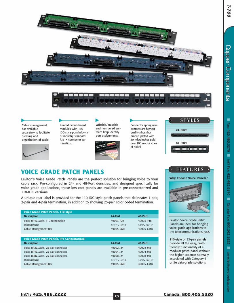
T-70
0
Int’l: 425.486.2222 Canada: 800.405.5320
Copper C
omponents
Fax: 4
25
.48
3.5
27
0
Int’l Fax: 42
5.4
85
.91
70
C
anada Fax: 80
0.5
63
.18
53
w
ww
.levitonvoicedata.comCopper C
omponents
C5
VVOICE GRADE POICE GRADE PAATCH PTCH PANELS ANELS Leviton's Voice Grade Patch Panels are the perfect solution for bringing voice to yourcable rack. Pre-configured in 24- and 48-Port densities, and designed specifically forvoice grade applications, these low-cost panels are available in pre-connectorized and110-IDC versions.
A unique rear label is provided for the 110-IDC style patch panels that delineates 1-pair,2-pair and 4-pair termination, in addition to showing 25-pair color coded termination.
Voice 8P4C Jacks, 110 termination 49003-P24 49003-P48
Dimensions: 1.75" H x 19.0" W 3.5" H x 19.0" W
Cable Management Bar 49005-CMB 49005-CMB
Voice Grade Patch Panels, 110-styleDescription 24-Port 48-Port
Voice 8P2C Jacks, 25-pair connector 49002-J24 49002-J48
Voice 8P4C Jacks, 25-pair connector 49004-J24 49004-J48
Voice 8P8C Jacks, 25-pair connector 49008-J24 49008-J48
Dimensions: 1.75" H x 19.0" W 3.5" H x 19.0" W
Cable Management Bar 49005-CMB 49005-CMB
Voice Grade Patch Panels, Pre-ConnectorizedDescription 24-Port 48-Port
Cable managementbar availableseparately to facilitatedressing andorganization of cable.
Printed circuit-boardmodules with 110IDC-style punchdownsor industry standardRJ21X connector ter-mination.
Writable/erasableand numbered sur-faces help identifyport assignments.
Connector spring wirecontacts are highestquality phosphorbronze, plated with50 microinches goldover 100 microinchesof nickel.
24-Port
48-Port
Leviton Voice Grade PatchPanels are ideal for bringingvoice-grade applications tothe telecommunications rack.
110-style or 25-pair panelsprovide all the easy, craft-friendly functionality of amodular patch panel withoutthe higher expense normallyassociated with Category 5or 5e data-grade solutions
Why Choose Voice Panels?

Fibe
r Com
pone
nts
Fibe
r Com
pone
nts
Cab
le M
anag
emen
tCab
le M
anag
emen
tTo
ols
& A
cces
sorie
sTo
ols
& A
cces
sorie
sCop
per
Com
pone
nts
Cop
per
Com
pone
nts
Wal
lpla
tes
& H
ousi
ngs
Wal
lpla
tes
& H
ousi
ngs
Con
nect
ors
Con
nect
ors
Tech
Sup
port
Tech
Sup
port
Customer Service: 800.722.2082www.levitonvoicedata.com C6
EXTREME 6+,EXTREME 6+, GIGAMAX 5E GIGAMAX 5E AND QUICKPORT AND QUICKPORT ANGLED PANGLED PAATCH PTCH PANELSANELS
48-Port eXtreme 6+ Angled Patch Panel 3.5” x 19.0” x 4.8” 69587-U48
48-Port GigaMax 5e Angled Patch Panel 3.5” x 19.0” x 4.8” 5G586-U48
QuickPort 48-Port Angled Patch Panel, sold empty 3.5” x 19.0” x 4.8” 49256-H48
Modular Angled Patch PanelsDescription Dimensions Part Number
Simplify cable management, ease patch cord access, andincrease rack density with new high-density Angled PatchPanels from Leviton. Constructed in a 128˚ wedge-shapedsilhouette, extending outward from any standard 19” rack.Modular panel available in GigaMax 5e or eXtreme 6+ versions,with 48 ports each. Field-configurable 48-port QuickPort versionaccommodates any style of QuickPort connector.
All loaded panels and blocks feature 110-style punchdownsand reversible rear designation labels with color-coded wiringdiagrams for T568A, T568B and 25-pair configurations.
Additionally, Angled Panels feature an array of accessories forrack management, including: Horizontal Ring, 1RU and 2RUAngled Blank Panel inserts, Transitional Cover and AngledCable Management Bar. All panels and blocks mount instandard 19" equipment racks and accommodate top,bottom or side cable entry. All panels and blocks are cULusListed and fully comply with all applicable Category 5e orCategory 6 standards.
Angled Panel Accessories
[A] Angled Cable Management Bar, rear 49006-AMB(4 Hook and Loop fasteners included )
[B] Vertical Transition Ring (Horizontal Cable Ring), 2/box 49262-HR1
[C] Front Blank Angled Panel, 2RU 49254-BA2
[D] Front Blank Angled Panel, 1RU 49254-BA1
[E] Transitional Cover 49254-BC1
A
Description Part Number
C
B
D
E
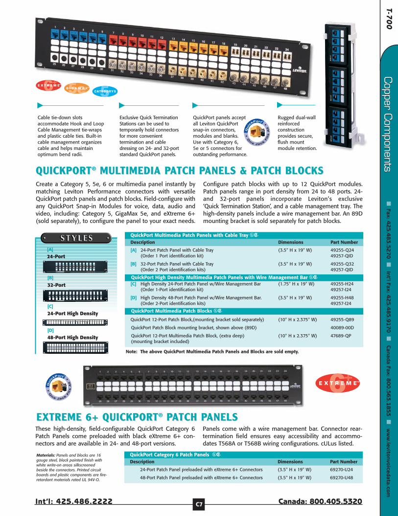
T-70
0
Int’l: 425.486.2222 Canada: 800.405.5320
Copper C
omponents
Fax: 4
25
.48
3.5
27
0
Int’l Fax: 42
5.4
85
.91
70
C
anada Fax: 80
0.5
63
.18
53
w
ww
.levitonvoicedata.comCopper C
omponents
C7
QUICKPORTQUICKPORT®® MULMULTIMEDIA PTIMEDIA PAATCH PTCH PANELS & PANELS & PAATCH BLOCKSTCH BLOCKS
[A] 24-Port Patch Panel with Cable Tray (3.5" H x 19" W) 49255-Q24(Order 1 Port identification kit) 49257-QID
[B] 32-Port Patch Panel with Cable Tray (3.5" H x 19" W) 49255-Q32(Order 2 Port identification kits) 49257-QID
QuickPort Multimedia Patch Panels with Cable Tray URDescription Dimensions Part Number
QuickPort High Density Multimedia Patch Panels with Wire Management Bar UR[C] High Density 24-Port Patch Panel w/Wire Management Bar (1.75" H x 19" W) 49255-H24
(Order 1-Port identification kit) 49257-I24
[D] High Density 48-Port Patch Panel w/Wire Management Bar. (3.5" H x 19" W) 49255-H48(Order 2-Port identification kits) 49257-I24
Rugged dual-wallreinforcedconstructionprovides secure,flush mountmodule retention.
Cable tie-down slotsaccommodate Hook and LoopCable Management tie-wrapsand plastic cable ties. Built-incable management organizescable and helps maintainoptimum bend radii.
Exclusive Quick TerminationStations can be used totemporarily hold connectorsfor more convenienttermination and cabledressing on 24- and 32-portstandard QuickPort panels.
Create a Category 5, 5e, 6 or multimedia panel instantly bymatching Leviton Performance connectors with versatileQuickPort patch panels and patch blocks. Field-configure withany QuickPort Snap-in Modules for voice, data, audio andvideo, including: Category 5, GigaMax 5e, and eXtreme 6+(sold separately), to configure the panel to your exact needs.
Configure patch blocks with up to 12 QuickPort modules.Patch panels range in port density from 24 to 48 ports. 24-and 32-port panels incorporate Leviton’s exclusive‘Quick Termination Station’, and a cable management tray. Thehigh-density panels include a wire management bar. An 89Dmounting bracket is sold separately for patch blocks.
QuickPort panels acceptall Leviton QuickPortsnap-in connectors,modules and blanks.Use with Category 6,5e or 5 connectors foroutstanding performance.
QuickPort Multimedia Patch Blocks UR
QuickPort 12-Port Patch Block,(mounting bracket sold separately) (10" H x 2.375" W) 49255-Q89
QuickPort Patch Block mounting bracket, shown above (89D) 40089-00D
QuickPort 12-Port Multimedia Patch Block, (extra deep) (10" H x 2.375" W) 47689-QP(mounting bracket included)
[B]
32-Port
[C]
24-Port High Density
[D]
48-Port High Density
Materials: Panels and blocks are 16gauge steel, black painted finish withwhite write-on areas silkscreenedbeside the connectors. Printed circuitboards and plastic components are fire-retardant materials rated UL 94V-O.
[A]
24-Port
EXTREME 6+ QUICKPORTEXTREME 6+ QUICKPORT®® PPAATCH PTCH PANELS ANELS
24-Port Patch Panel preloaded with eXtreme 6+ Connectors (3.5" H x 19" W) 69270-U24
48-Port Patch Panel preloaded with eXtreme 6+ Connectors (3.5" H x 19" W) 69270-U48
QuickPort Category 6 Patch Panels URDescription Dimensions Part Number
These high-density, field-configurable QuickPort Category 6Patch Panels come preloaded with black eXtreme 6+ con-nectors and are available in 24- and 48-port versions.
Panels come with a wire management bar. Connector rear-termination field ensures easy accessibility and accommo-dates T568A or T568B wiring configurations. cULus listed.
Note: The above QuickPort Multimedia Patch Panels and Blocks are sold empty.

Fibe
r Com
pone
nts
Fibe
r Com
pone
nts
Cab
le M
anag
emen
tCab
le M
anag
emen
tTo
ols
& A
cces
sorie
sTo
ols
& A
cces
sorie
sCop
per
Com
pone
nts
Cop
per
Com
pone
nts
Wal
lpla
tes
& H
ousi
ngs
Wal
lpla
tes
& H
ousi
ngs
Con
nect
ors
Con
nect
ors
Tech
Sup
port
Tech
Sup
port
Customer Service: 800.722.2082www.levitonvoicedata.com C8
[C] Lev-UPS Slim Uninterruptible Power SupplyDescription Part Number
Lev-UPS Slim Uninterruptible Power Supply U0600-ARM
RARACK-MOUNT SURGE PROCK-MOUNT SURGE PROTECTIVE DEVICESTECTIVE DEVICES5500 Series 19-inch Rack-Mount Surge Protective Device[A, B] Designed to mount on 19-inch racks, providing transient voltage surge suppression-for rack-mounted electronic equipment. Offers 12 protected outlets (15A or 20A versions),10 in the back of the unit, and 2 in the front. Advanced circuit design offers extremely tightclamping levels and exceptional noise attenuation. Choose between Normal or Commonprotection modes. Features on-off rocker switch, power protection and outletpolarity/ground status LED diagnostics, a resettable overload circuit breaker and 12-footpower supply cord. Unit will continue to provide power if protection is lost. Tested toANSI/IEEE C62.41 standards. 330 Volts peak. UL Listed & CSA Certified
5500 Series Rack-Mount Surge Protective DeviceDescription Part NumberNEMA 5-15P Standard Blade Plug[A] 125V, 15A Surge Protective Device, with on/off switch (12 outlets) 5500-190
125V, 15A Surge Protective Device, without on/off switch (12 outlets) 5500-15N
125V, 20A Surge Protective Device, with on/off switch (12 outlets) 5500-192
[B] 125V, 20A Surge Protective Device, without on/off switch (12 outlets) 5500-20N
NEMA L5-15P Locking Plug125V, 15A Surge Protective Device, with on/off switch (12 outlets) 5500-15L
125V, 15A Surge Protective Device, without on/off switch (12 outlets) 5500-NL
125V, 20A Surge Protective Device, with on/off switch (12 outlets) 5500-20L
125V, 20A Surge Protective Device, without on/off switch (12 outlets) 5500-2NL
Lev-UPS™ Slim Uninterruptible Power Supply[C] This slim low-profile 1RU Uninterruptible Power Supply is designed to mount on a stan-dard 19-inch rack, provides mitigation for sags and swells in power quality without relyingon transfer to back-up power. Provides AC (5 outlets) and data/communication line surgeprotection (1 parallel port and 2 RJ-45 outlets). Features a “Cold Start” mode that allows theUPS to be used as a short term emergency power source (25 minutes back up time). User-replaceable batteries. Dry-relay contact for remote signaling of basic functions. cULus Listedand FCC Compliant.
[D] Lev-UPS On-Line Uninterruptible Power SupplyDescription Tower Configuration Rack Mount
Lev-UPS Online UPS, 1000 VA capacity U1000-ONL U1000-ORM
Lev-UPS Online UPS, 2000 VA capacity U2000-ONL U2000-ORM
Lev-UPS Online UPS, 3000 VA capacity U3000-ONL U3000-ORM
Lev-UPS™ On-Line Uninterruptible Power Supply[D] The highest grade of power protection available. State-of-the-art double-conversiondesign makes this unit ideal for critical and power-sensitive applications. Provides AC (5 out-lets) and data/communication line surge protection (1 parallel port and 2 RJ-45 outlets).Smooths power fluctuations and protects against spikes, surges, noise, extended over andunder voltages, harmonics and frequency variations. Dual microprocessors ensure uninter-rupted power to the load in the event of a UPS fault. LCD display and audible alarms indicatestatus. and parameters. Includes Lev-WARE power monitoring software. Features solid-stateremote control & signaling and a “Cold Start” mode that allows the UPS to be used as a shortterm emergency power source. cULus Listed.
C
D
A
B

T-70
0
Int’l: 425.486.2222 Canada: 800.405.5320
Copper C
omponents
Fax: 4
25
.48
3.5
27
0
Int’l Fax: 42
5.4
85
.91
70
C
anada Fax: 80
0.5
63
.18
53
w
ww
.levitonvoicedata.comCopper C
omponents
C9
24-Port ID Kit (for 12-, 24-, 48- and 96-port panels, 24- & 48-port High-Density Panels) 49257-I24(two kits required for 48-port & four kits required for 96-port panels)
QuickPort 32-port ID kit (for 24- and 32-port panels) 49257-QID
[D] Patch Panel Port Identification KitsDescription Part Number
Patch Panel Port Identification Kits
[E, F] Blank Panels (for standard 19” equipment racks)Description 1RU 2RU 3RU
Blank Panels
A
D
E
[E] Front Blank Panel, Standard 49254-BP1 49254-BP2 49254-BP4
[F] Front Blank Panel, Angled 49254-BA1 49254-BA2
[G] Hinged Wall-Mount Brackets URDescription 2RU 3RU 4RU
Hinged Wall-Mount Brackets
GHinged Wall-Mount Bracket 49251-W62 49251-W63 49251-W64
B
C
RARACK & PCK & PANEL ANEL AACCESSORIESCCESSORIES
F
PERFORMANCE PPERFORMANCE PAATCH CORDSTCH CORDS[A-C] Leviton’s eXtreme™ 6+, GigaMax™ 5e and Category 5 patch cords meet or exceedindustry standard specifications, and use compliant stranded wire as specified by the latestpublished TIA guidelines to ensure adequate 'flex life.' All have quality construction tomaintain the integrity of signal transmission at the cross-connect, which is critical tothe performance of the entire cabling system.
GigaMax 5e Patch Cords are suitable for Category 5e and 5e+ applications, andeXtreme 6+ Patch Cords are suitable for Category 6 applications. Both GigaMaxand eXtreme Cords meet component specifications as outlined in the latest TIAguidelines.
Available in lengths of 3', 5', 7', 10', 15' and 20'. Offered in seven colors: white, red,yellow, green, blue, grey and black. GigaMax 5e cords feature black strain-relief boots, andeXtreme 6+ cords feature stranded cable and color-coordinated slimline boots. Category5 cords have no strain-relief boot.
NOTE: Leviton Performance Patch Cords are required to qualify for the Leviton Lifetime Warranty onCertified installations.
[A-C] Patch Cords U
Description [A] eXtreme 6 [B] GigaMax 5e [C] Category 5
3-foot length 62460-03* 5G455-03* 52455-03*
5-foot length 62460-05* 5G455-05* 52455-05*
7-foot length 62460-07* 5G455-07* 52455-07*
10-foot length 62460-10* 5G455-10* 52455-10*
15-foot length 62460-15* 5G455-15* 52455-15*
20-foot length 62460-20* 5G455-20* 52455-20*
*=Color choices: White(W), Grey(S), Black(E), Blue(L), Red(R), Green(G), Yellow(Y)
CAT 6
SLIMLINE
BOOTS

Fibe
r Com
pone
nts
Fibe
r Com
pone
nts
Cab
le M
anag
emen
tCab
le M
anag
emen
tTo
ols
& A
cces
sorie
sTo
ols
& A
cces
sorie
sCop
per
Com
pone
nts
Cop
per
Com
pone
nts
Wal
lpla
tes
& H
ousi
ngs
Wal
lpla
tes
& H
ousi
ngs
Con
nect
ors
Con
nect
ors
Tech
Sup
port
Tech
Sup
port
Customer Service: 800.722.2082www.levitonvoicedata.com C10
110 110 WIRING PRODUCTSWIRING PRODUCTSWall-Mount 110 Wiring ProductsCreate compact, adaptable 110 termination fields for voice and data by mounting 110wiring bases to the wall or a backboard. Bases come in 50-, 100- or 300-pair densities. The50- and 100- pair bases may be ordered with or without standoff legs which provide moreroom behind the base for cable. All 300-pair bases include standoff legs, label strip holdersand white paper labels. A 50-pair 89D bracket configuration is also available (89D bracketsold separately, C13).
Complete kits are available for 100- and 300-pair wall-mount units and 89D wiring base, andinclude bases, C-4 & C-5 connecting blocks, label holders and white paper labels.
All components are UL Listed and exceed latest TIA-568-B standards and Category 5e trans-mission requirements. Verified by independent testing.
Wall-Mount 110 Products - Individual Components & Combinations U
[A] 50-pair Wall-Mount Wiring Base without legs 41DW1-50
Legs only, 50-Pair Base (set of two) for 41DW1-50 410L2-50
[B] 100-pair Wall-Mount Wiring Base without legs 41DW2-100
[C] Legs only, 100-Pair Base (set of two) for 41DW2-100 410L2-100
[D] 50-pair Wall-Mount Wiring base with legs 41AW1-50
[E] 100-Pair Wall-Mount Wiring Base with legs 41AW2-100
[F] 300-pair Wall-Mount Wiring Base with legs and white label strips/holders 41AW2-300
[G] Horizontal Cord Manager without legs 41D10-HCM
[H] Horizontal Cord Manager with legs 41A10-HCM
[I] 50-pair 89D Bracket compatible wiring base
(89D bracket sold separately, part number 40089-D) 41DW1-589
Description Part Number
Wall-Mount 110 Products - Kitted Versions
[J] 100-pair Wall-Mount Wiring Base Kit with base, legs, label strip 41AB2-1FTholders, white label strips, 20 C-4 connectors and 4 C-5 connectors.
300-pair Wall-Mount Wiring Base Kit with base, legs, label strip 41AB2-3FTholders, white label strips, 60 C-4 connectors and 12 C-5 connectors.
50-pair 89D Bracket compatible wiring base kit with base, label 41DB1-5FTstrip holders, white label strips, 10 C-4 connectors and 2 C-5 connectors(89D Bracket sold separately, part number 40089-D).
Description Part Number
Materials:Horizontal cord managers and 110wiring bases feature sturdysingle-piece construction offire-retardant plastic rated UL 94V-0.C-4 and C-5 connector blocks (soldseparately or included in kittedversions) are fire-retardant UL 94V-0plastic with solder-plated IDC’s.
Kits available for 100- and 300-pairwiring bases (100-pair is shownbelow), and 50-pair 89D wiring base.
J
F
E
H
I
A
B
G
C
D
Category 6 110 Connector Block Kit
Category 6 110 Connector Block Kit 41AB6-1FT
Description Part Number
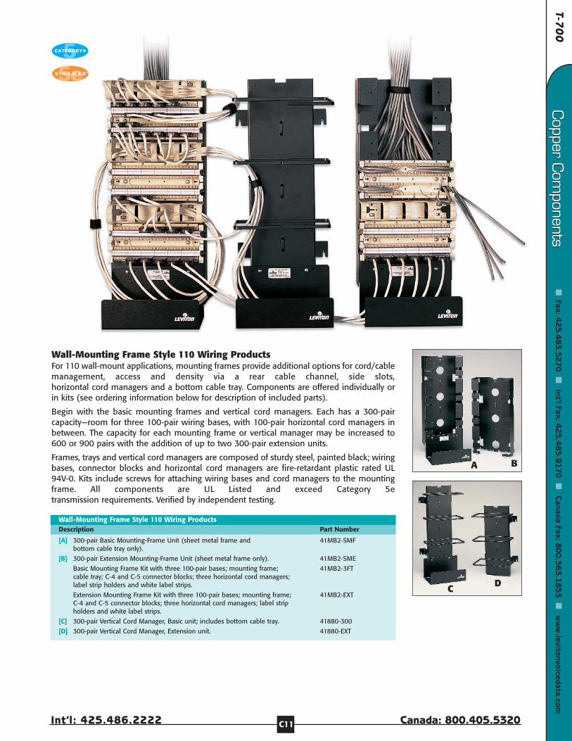
T-70
0
Int’l: 425.486.2222 Canada: 800.405.5320
Copper C
omponents
Fax: 4
25
.48
3.5
27
0
Int’l Fax: 42
5.4
85
.91
70
C
anada Fax: 80
0.5
63
.18
53
w
ww
.levitonvoicedata.comCopper C
omponents
C11
Wall-Mounting Frame Style 110 Wiring Products For 110 wall-mount applications, mounting frames provide additional options for cord/cablemanagement, access and density via a rear cable channel, side slots,horizontal cord managers and a bottom cable tray. Components are offered individually orin kits (see ordering information below for description of included parts).
Begin with the basic mounting frames and vertical cord managers. Each has a 300-paircapacity—room for three 100-pair wiring bases, with 100-pair horizontal cord managers inbetween. The capacity for each mounting frame or vertical manager may be increased to600 or 900 pairs with the addition of up to two 300-pair extension units.
Frames, trays and vertical cord managers are composed of sturdy steel, painted black; wiringbases, connector blocks and horizontal cord managers are fire-retardant plastic rated UL94V-0. Kits include screws for attaching wiring bases and cord managers to the mountingframe. All components are UL Listed and exceed Category 5etransmission requirements. Verified by independent testing.
Wall-Mounting Frame Style 110 Wiring Products
[A] 300-pair Basic Mounting-Frame Unit (sheet metal frame and 41MB2-SMFbottom cable tray only).
[B] 300-pair Extension Mounting-Frame Unit (sheet metal frame only). 41MB2-SME
Basic Mounting Frame Kit with three 100-pair bases; mounting frame; 41MB2-3FTcable tray; C-4 and C-5 connector blocks; three horizontal cord managers; label strip holders and white label strips.
Extension Mounting Frame Kit with three 100-pair bases; mounting frame; 41MB2-EXTC-4 and C-5 connector blocks; three horizontal cord managers; label strip holders and white label strips.
[C] 300-pair Vertical Cord Manager, Basic unit; includes bottom cable tray. 41880-300
[D] 300-pair Vertical Cord Manager, Extension unit. 41880-EXT
Description Part Number
B
C
A
D
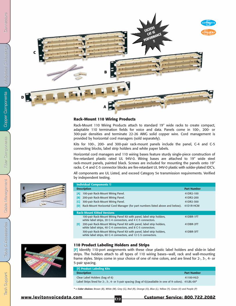
Fibe
r Com
pone
nts
Fibe
r Com
pone
nts
Cab
le M
anag
emen
tCab
le M
anag
emen
tTo
ols
& A
cces
sorie
sTo
ols
& A
cces
sorie
sCop
per
Com
pone
nts
Cop
per
Com
pone
nts
Wal
lpla
tes
& H
ousi
ngs
Wal
lpla
tes
& H
ousi
ngs
Con
nect
ors
Con
nect
ors
Tech
Sup
port
Tech
Sup
port
Customer Service: 800.722.2082www.levitonvoicedata.com C12
110 Product Labeling Holders and Strips[F] Identify 110-port assignments with these clear plastic label holders and slide-in labelstrips. The holders attach to all types of 110 wiring bases—wall, rack and wall-mountingframe styles. Strips come in your choice of one of nine colors, and are lined for 2-, 3-, 4- or5-pair spacing.
[F] Product Labeling Kits
Clear Label Holders (bag of 6) 41100-HLD
Label Strips lined for 2-, 3-, 4- or 5-pair spacing (bag of 6)(available in one of 9 colors). 41LBL-00*
Description Part Number
F
Individual Components U
[A] 100-pair Rack-Mount Wiring Panel. 41DR2-100
[B] 200-pair Rack-Mount Wiring Panel. 41DR2-200
[C] 300-pair Rack-Mount Wiring Panel. 41DR2-300
[D] Rack-Mount Horizontal Cord Manager (for part numbers listed above and below). 41D1R-HCM
Description Part Number
Rack-Mount Kitted Versions100-pair Rack-Mount Wiring Panel Kit with panel, label strip holders, 41DBR-1FTwhite label strips, 20 C-4 connectors, and 4 C-5 connectors.
[E] 200-pair Rack-Mount Wiring Panel Kit with panel, label strip holders, 41DBR-2FTwhite label strips, 40 C-4 connectors, and 8 C-5 connectors.
300-pair Rack-Mount Wiring Panel Kit with panel, label strip holders, 41DBR-3FTwhite label strips, 60 C-4 connectors, and 12 C-5 connectors.
E
C
D
B
A
* = Color choices: Brown (B), White (W), Grey (G), Red (R), Orange (O), Blue (L), Yellow (Y), Green (V) and Purple (P)
EXCEEDS
CAT 5E
PERFORMANCE
!!
Rack-Mount 110 Wiring Products Rack-Mount 110 Wiring Products attach to standard 19" wide racks to create compact,adaptable 110 termination fields for voice and data. Panels come in 100-, 200- or300-pair densities and terminate 22-26 AWG solid copper wire. Cord management isprovided by horizontal cord managers (sold separately).
Kits for 100-, 200- and 300-pair rack-mount panels include the panel, C-4 and C-5connecting blocks, label strip holders and white paper labels.
Horizontal cord managers and 110 wiring bases feature sturdy single-piece construction offire-retardant plastic rated UL 94V-0. Wiring bases are attached to 19" wide steelrack-mount panels, painted black. Screws are included for mounting the panels onto 19"racks. C-4 and C-5 connector blocks are fire-retardant UL 94V-0 plastic with solder-plated IDC’s.
All components are UL Listed, and exceed Category 5e transmission requirements. Verifiedby independent testing.

T-70
0
Int’l: 425.486.2222 Canada: 800.405.5320
Copper C
omponents
Fax: 4
25
.48
3.5
27
0
Int’l Fax: 42
5.4
85
.91
70
C
anada Fax: 80
0.5
63
.18
53
w
ww
.levitonvoicedata.comCopper C
omponents
C13
[A] 110 Connector Clips U
C-3 Connector Clips (bag of 10) 49103-IDC
C-4 Connector Clips (bag of 10) 49104-IDC
C-4 Connector Clips (bag of 50) 49104-I50
C-5 Connector Clips (bag of 10) 49105-IDC
Description Part Number
110 Connector Clips[A] These high-quality connector clips securely seat the wires on 110 wiring bases,providing a gas-tight IDC connection that maintains signal integrity for high performanceapplications. Available in three Category 5/5e pair-count sizes: C-3, C-4 and C-5. Theseblocks withstand 200 reterminations, and are made of fire-retardant plastic rated UL 94V-0with solder-plated insulation displacement connectors.
Bridging Clips[B] Clips press onto the two center slots in any row of a Split M block (as shown at left). Ifoutside cable pairs are terminated on left-hand clips and station equipment wire isterminated on right-hand clips, then connections may be made or eliminated easily just byinserting or removing the bridging clips. They can also be used on other products which use66-clips. Made of tin-plated phosphor bronze alloy, these clips can be easily removed andreused for rewiring.
Bridging Clips
Wire Distribution Spool [C] Facilitates routing and fanning of cable, cross-connections, and jumper wires to any con-nection apparatus. Mounts conveniently on backboard of distribution frame.
Wire Distribution Spool with Screw [D] Includes captive wood screw for quick backboard mounting.
Wire Distribution Spools
Modular Adapter[E] Plugs into M blocks to convert 66-clip contacts to a modular jack for quick connection ofequipment.
[E] Modular Adapter
Materials:• Housings: High-impact,
fire-retardant plastic ratedUL 94V-0.
• Spring wire contacts: Phosphorbronze plated with 50 microincheshard gold over 100 microinchesnickel.
• Wire leads: PVC-insulated 26 AWGstranded copper.
B
C
D
E
[B] Bridging Clips (SA-I), bag of 50 only 40067-BC
Description Part Number
[C] Wire Distribution Spool (20-A) 1-3/4" Dia. x 3" H 40054-DS
[D] Wire Distribution Spool with screw (20-B) 1-3/4" Dia. x 3" H 40054-DSS
Description Part Number
2-Position Modular Adapter 40072-T2 Converts two 66-clip contacts into(Tap™-2) a 6-position, 2-conductor modular
jack
4-Position Modular Adapter 40072-T4 Converts four contacts into a(Tap™-4) 6-position, 4-conductor modular jack
6-Position Modular Adapter 40072-T6 Converts six contacts into a(Tap™-6) 6-position, 6-conductor modular jack
8-Position Modular Adapter, T568B wiring 40072-T8 Converts eight contacts into an(Tap™-8) 8-position, 8-conductor non-keyed
modular jack
Description Part Number
Note: Numbers in parenthesis refer to industry product designation.
Note: Numbers in parenthesis refer to industry product designation.
Note: TAP is a trademark of The Siemon Company.
A

Fibe
r Com
pone
nts
Fibe
r Com
pone
nts
Cab
le M
anag
emen
tCab
le M
anag
emen
tTo
ols
& A
cces
sorie
sTo
ols
& A
cces
sorie
sCop
per
Com
pone
nts
Cop
per
Com
pone
nts
Wal
lpla
tes
& H
ousi
ngs
Wal
lpla
tes
& H
ousi
ngs
Con
nect
ors
Con
nect
ors
Tech
Sup
port
Tech
Sup
port
Customer Service: 800.722.2082www.levitonvoicedata.com C14
66-CLIP CONNECTING BLOCKS66-CLIP CONNECTING BLOCKSThese industry-standard blocks are used in equipment rooms to connect voice and data net-work wiring to customer premises equipment. They are also used in remote andintermediate wiring closets throughout larger installations as common connecting points fornearby equipment. Constructed of high-impact, fire-retardant molded thermoplastic, Levitonconnecting blocks utilize phosphor bronze quick-connect insulation displacement 66-clipsfor ease of installation, and proven mechanical and electrical reliability.
The 66 blocks may be installed individually or in pairs in a cross-connect system tofacilitate subsequent adds, moves, and changes. In a cross-connect system, jumper wires areused to make connections between blocks. Stations can then be disconnected and reas-signed without disturbing station wire—simply by moving the jumpers. Bridging clips cansometimes be used on split 50 blocks in place of jumpers.
M Block: 25-Pair [A] Contains 50 rows, each with a single clip having four slots as shown at left. Incomingcable pairs are connected by terminating the tip conductor on the leftmost slot of one row,and the ring conductor on the leftmost slot of the next lower row. The threeremaining slots in each clip are available for cross-connects.
Split M Block: 50-Pair [B] The split M block, like the 25-pair M block, contains 50 rows of clips, but instead of one4-slot clip, each row contains two separate 2-slot clips. By terminating 25 incoming pairs onthe slots of the left-hand clips and an additional 25 pairs on the slots of theright-hand clips, 50 cross-connects can be made. Alternatively, bridging clips may be usedto connect the two adjacent sets of clips together. (See Page C9.)
M Block with Female Connector [C] 50-pair M block with prewired, pretested 25-pair female connector on left sidefanning strip to speed connection of incoming pairs.
M Block with Female and Male Connectors[D] 50-pair M block with prewired, pretested 25-pair female connector on left and maleconnector on right for fastest installation. Simply plug in connectors and insert bridging clipsto complete the connections.
Connectorized Demarc Block[E] Designed for use at the demarcation point, this 50-pair M block includes mountingbracket and snap-on orange cover with designation strip. Prewired, pretested 25-pair femaleconnector mounted on right side speeds connection of customer premiseequipment to the network interface.
66 Clip Connecting Blocks U
[A] M Block: 25-pair (66M1-25) 10" H x 3-5/16" W x 1-3/16" D 40066-M25
[B] Split M Block: 50-pair (66M1-50) 10" H x 3-5/16" W x 1-3/16" D 40066-M50
[C] M Block with female connector (66M1-50W) 10" H x 3-5/16" W x 1-3/16" D 40066-MW
[D] M Block with female and male connectors (66M1-50W2) 40066-MW2 10" H x 3-5/16" W x 1-3/16" D
[E] Connectorized Demarc Block (66M1-50R) 10" H x 3-13/32" W x 2-3/4" D 40066-MR
Description Part Number
A
C
E
D
B
Note: Numbers in parentheses refer to industry product designation.

T-70
0
Int’l: 425.486.2222 Canada: 800.405.5320
Copper C
omponents
Fax: 4
25
.48
3.5
27
0
Int’l Fax: 42
5.4
85
.91
70
C
anada Fax: 80
0.5
63
.18
53
w
ww
.levitonvoicedata.comCopper C
omponents
C15
66-CLIP CONNECTING BLOCK 66-CLIP CONNECTING BLOCK AACCESSORIESCCESSORIESSnap-On Cover for M Blocks [B] Snaps onto 25- and 50-pair M blocks to protect wiring from dust, dirt and incidentalshorting. Transparent plastic permits viewing of wiring and pair assignments. Durable,fire-retardant thermoplastic.
Snap-On Cover for M Blocks
Hinged Cover for Demarc Blocks [C] Colored orange to identify the network demarcation point, this hinged cover snaps ontothe right side fanning strip of 25- and 50-pair M blocks to protect wiring from dust, dirt andincidental shorting. Allows wires to be routed from both left and right sides. Designationstrip included on inside for recording pair assignments.
Hinged Cover for M Blocks [D] Snaps into the right side fanning strip of 25- and 50-pair M blocks. Protects wiring fromdust, dirt, and incidental shorting. Allows wires to be routed from both left and right sides.Designation strip included on inside for recording pair assignments.
Hinged Covers for Demarc and M Blocks
Standoff Bracket for M Blocks [E] Standard mounting bracket for use with all 25- and 50-pair M blocks.
M-Block Bracket for Jack/Connector Mounting [F] Standoff bracket for 25- and 50-pair M blocks, 89D 110 wiring bases (page C6), andQuickPort Patch Blocks (page C4). Bracket is open at top and bottom so that installers maymount bracket and lay cable, then install connecting block easily at a later date.
[B] Snap-on Cover for M blocks (66MC-4) 9-15/16" H x 2-5/16" W x 5/16" D 40050-MCV
Description Part Number
[C] Hinged Cover for demarc blocks: orange (66MC4LH-O) 10" H x 2-7/16" W x 3/4" D 40050-MH0
[D] Hinged Cover for M blocks: grey (66MC4LH-G) 10" H x 2-7/16" W x 3/4" D 40050-MHG
Description Part Number
[E] Standoff Bracket for M blocks (89-B) 10" H x 3-13/32" W x 1-1/2" D 40089-B
[F] M-block Bracket for jack/connector mounting (89-D) 10" H x 3-13/32" W x 1-1/2" D 40089-D
Description Part Number
B
C
E
F
D
Prewired 66 Blocks[A] The 66 M1-50 block and 89-D bracket come preassembled with designated jacks.
Prewired 66 Blocks U
12 6p4c Jacks 49114-QIA
12 6p6c Jacks 49112-QIA
12 8p8c Jacks, T568B 49111-QIA
Description Part Number
Materials: 25-pair connector terminals: High-strength copper alloy, selectively gold plated over nickel in contact area. 25-pairconnectors meet the requirements of FCC Part 68 for standard telecommunications interface (RJ21X).
A
Note: Number in parenthesis refers to industry product designation.
Note: Numbers in parenthesis refer to industry product designation.
Note: Numbers in parenthesis refer to industry product designation.
Standoff Bracket for M Blocks and M-Block Bracket for Jack/Connector Mounting U

Fibe
r Com
pone
nts
Fibe
r Com
pone
nts
Cab
le M
anag
emen
tCab
le M
anag
emen
tTo
ols
& A
cces
sorie
sTo
ols
& A
cces
sorie
sCop
per
Com
pone
nts
Cop
per
Com
pone
nts
Wal
lpla
tes
& H
ousi
ngs
Wal
lpla
tes
& H
ousi
ngs
Con
nect
ors
Con
nect
ors
Tech
Sup
port
Tech
Sup
port
Customer Service: 800.722.2082www.levitonvoicedata.com C16
SURFSURFAACE-MOUNT MINI PCE-MOUNT MINI PAATCH PTCH PANELSANELSFor applications where space limitations or simple breakout patching does not justify theuse of rack-mounted patch panels, Leviton offers a full-function Mini Patch Panel withmodular jacks that can be mounted almost anywhere—even in cramped quarters.Combine two or more panels in-line and use patch cords to make and changeconnections. Leviton’s modular jack design suits most voice and data applications.
Surface-Mount Mini Patch Panels US
[A] 25 6-position 2-conductor (RJ11) FCC Spec Jacks connected to a circuit board 41600-Iwith one male 25-pair connector in surface-mount housing. Wired in standard T-R sequence (26-1, 27-2, 28-3, etc).
[B] 25 6-position 4-conductor (RJ14) FCC Spec Jacks wired into two male 25-pair 41610-Iconnectors in standard T-R sequence.
[C] 25 6-position 2-conductor (RJ11) FCC Spec Jacks connected to a circuit board 41620-Iwith two bridged 25-pair connectors (one male and one female) in standard T-R sequence for series connection.
Description Part Number
A
Materials:Surface-Mount Mini Patch Panels• Housings: High-impact,
fire-retardant plastic ratedUL 94V-0.
• Connector terminals: High-strengthcopper alloy, selectively gold platedover nickel in contact area.
• Connectors meet the requirementsof FCC Part 68 for standardtelecommunications interface(RJ21X).
B
C
Low-Profile Rack-Mount Fiber Enclosures D4
Universal Fiber Optic Enclosures D5
Rack-Mount Fiber Optic Enclosures D6
Wall-Mount Fiber Optic Enclosures D7
Fiber Optic Cable Assemblies D8
Fiber Optic Accessories D9

Fibe
r Com
pone
nts
Fibe
r Com
pone
nts
Cab
le M
anag
emen
tCab
le M
anag
emen
tTo
ols
& A
cces
sorie
sTo
ols
& A
cces
sorie
sCop
per
Com
pone
nts
Cop
per
Com
pone
nts
Wal
lpla
tes
& H
ousi
ngs
Wal
lpla
tes
& H
ousi
ngs
Con
nect
ors
Con
nect
ors
Tech
Sup
port
Tech
Sup
port
Customer Service: 800.722.2082www.levitonvoicedata.com D2
Related Products
FIBER OPTIC CONNECTFIBER OPTIC CONNECTORS ORS ANDANDQUICKPORT QUICKPORT ADADAPTERSAPTERS
Innovative, craft-friendly ST, SC, FC, MT-RJ andLC connectors, in mechanical or epoxy styles.
Plus adapters to fit them to any QuickPort® housing (Page A6).
Fiber ComponentsMove your data into the next dimension of networking. Leviton offers fiber solutionsfor all types of installations: ST®, SC, FC, MT-RJ, LC or any combination thereof. In thischapter find Wall-mount or Rack-mount Fiber Enclosures, a complete selection ofFiber Optic Mounting Plates to fit in them, an extensive line of Fiber Optic CableAssemblies and Pigtails, and a variety of accessories and adapters.
MULMULTIMEDIA OUTLET SYTIMEDIA OUTLET SYSTEM (MOS)STEM (MOS)Flexible wallplate system ideal for networks
with high volume adds, moves and changes (Page B8).
VERSI-DUCTVERSI-DUCT™™ SLOSLOTTED DUCT SYTTED DUCT SYSTEMSTEMVersatile vertical and horizontal rack cable
management system with an array of innovative accessories (Page E3).
HOOK &HOOK & LOOP CLOOP CABLE MANAABLE MANAGEMENTGEMENTRe-usable Hook and Loop solutions to
protect cables and keep work and closet areas neat (Page B8).
FIBER OPTIC FIBER OPTIC TTOOL KITSOOL KITSFiber tool kits for SC, ST, FC, MT-RJ and LC,mechanical or epoxy connectors (Page F4).
DIADIAGRAMS &GRAMS & INSTRUCTIONSINSTRUCTIONSIn our appendix, find step-by-step
termination instructions for Thread-Lock,Spectro-LInk and Fast Cure Connector
types (Page X1).
DIMENSIONAL DIADIMENSIONAL DIAGRAMS &GRAMS &GLOSSARGLOSSARY OF Y OF TERMSTERMS
Dimensional diagrams for fiberoptic connectors, panels and accessories, as well
as a complete glossary of terms, are availablein our appendix section (Page X1).

T-70
0
Int’l: 425.486.2222 Canada: 800.405.5320
Fiber Com
ponents
Fax: 42
5.4
83
.52
70
Int’l Fax: 4
25
.48
5.9
17
0
Canada Fax: 8
00
.56
3.1
85
3
ww
w.levitonvoicedata.com
Fiber Com
ponents
D3
FIBER OPTIC ENCLOSURESFIBER OPTIC ENCLOSURES
Rack-mount doors fold downas a work tray or removecompletely for more accessto the enclosure.
Exclusive self-healinggrommet material at all cableingress/egress points easescable in, keeps dust out.
Fiber storage rings areexpandable and stackable touniquely simplify installationor maintenance of multiple3-meter fiber loops, and alloweasy future additions—whilepreserving proper bend radius.
Slide rail option on 1.75",3.5" & 5.25" high rack-mountenclosures allows easy instal-lation and re-entry from frontor back, regardless of equip-ment or enclosures above.
• Flexible, trimmable, self-healing grommets at allcable ingress/egress points provide unequalledfit and dust resistance.
• Cable strain relief/tie-down features areabundant throughout each enclosure.
• Hardware and label kit included with eachenclosure.
• Dual cable management rings simplify fiber loopinstallation, bend radius compliance, and futuremaintenance/additions for storage of 3 meters of900 micron fiber per coupling.
• Vertical cable pass-throughs at both front andrear of enclosure are sized for 1.25" innerduct toallow patching between enclosures withoutexiting the enclosure.
• Completely removable doors provideunobstructed access to the enclosure interior.

Fibe
r Com
pone
nts
Fibe
r Com
pone
nts
Cab
le M
anag
emen
tCab
le M
anag
emen
tTo
ols
& A
cces
sorie
sTo
ols
& A
cces
sorie
sCop
per
Com
pone
nts
Cop
per
Com
pone
nts
Wal
lpla
tes
& H
ousi
ngs
Wal
lpla
tes
& H
ousi
ngs
Con
nect
ors
Con
nect
ors
Tech
Sup
port
Tech
Sup
port
Customer Service: 800.722.2082www.levitonvoicedata.com D4
A
D
C
B
Completely removabletop with tilt-up,removable frontprovides unobstructedaccess to theenclosure interior.
Mounting bracketsare reversible formid- or flush-mounting in 19"racks.
High-density adapter bulk-head houses up to 24 ST®
or 12 duplex SC adapters.Another version acceptstwo six-fiber mountingplates; configure with ST,FC, SC, LC and MT-RJ or adda QuickPort plate to createa multimedia enclosure.
D
24 Fiber ST Bulkhead w/6 adapters 5R030-0AB
24 Fiber SC Bulkhead w/3 duplex adapters 5R030-0HB
12-48 Fiber, empty (accepts 2 bulkheads, sold sep.) 5R130-00N
12 Fiber, loaded w/ST adapters 5R230-0AB
24 Fiber, loaded w/6 duplex SC adapters 5R230-0HB
24 Fiber, unloaded, punched for ST adapters 5R330-0AA
24 Fiber, unloaded, punched for duplex SC adapters 5R330-0HA
24 Fiber loaded w/ST adapters 5R330-0AB
24 Fiber loaded w/12 duplex SC adapters 5R330-0HB
Low-Profile Rack-Mount Enclosures (1RU) w/o Rails U
1.75"H x 19.0"W x 12.0"DDescription Part Number
Slide Rail Kit for 0-24 or 0-72 fiber
Rack-Mount enclosures only 5S100-SLM
24 Fiber Rack-Mount Metal Replacement Door 5D000-1RM
Add-On Slide Rail Kit
Replacement Door
24 Fiber ST Bulkhead w/6 adapters 5P030-0AB
24 Fiber SC Bulkhead w/3 duplex adapters 5P030-0HB
12-48 Fiber empty (accepts 2 bulkheads, sold sep.) 5P130-00N
12 Fiber loaded w/ST adapters 5P230-0AB
24 Fiber loaded w/6 duplex SC adapters 5P230-0HB
0-24 Fiber unloaded, punched for ST adapters 5P330-0AA
0-24 Fiber unloaded, punched for duplex SC adapters 5P330-0HA
24 Fiber loaded w/ST adapters 5P330-0AB
24 Fiber loaded w/12 duplex SC adapters 5P330-0HB
Low-Profile Rack-Mount Enclosure (1RU) w/Rails U1.75" H x 19.0" W x 12.0" DDescription Part Number
CBA
LOLOWW-PROFILE RA-PROFILE RACK-MOUNT FIBER OPTIC ENCLOSURESCK-MOUNT FIBER OPTIC ENCLOSURES
LOADED = The enclosure’s bulkhead contains the specified couplings. UNLOADED = The enclosure includes a bulkhead which has openings for, but doesnot include, the specified couplings.EMPTY = No bulkhead coupling plates are included.
Note: For mounting plates and accessories, see page D9.
Slide rail optionallows easyinstallation andre-entry regardlessof equipment orenclosures above.
SEE FIBER
DENSITY
CHART,
PAGE D9
0-24 ST connector bulkhead
0-24 SC connector bulkhead
Two six pack plate bulkhead

T-70
0
Int’l: 425.486.2222 Canada: 800.405.5320
Fiber Com
ponents
Fax: 42
5.4
83
.52
70
Int’l Fax: 4
25
.48
5.9
17
0
Canada Fax: 8
00
.56
3.1
85
3
ww
w.levitonvoicedata.com
Fiber Com
ponents
D5
2RU UNIVERSAL FIBER OPTIC ENCLOSURE2RU UNIVERSAL FIBER OPTIC ENCLOSURE
2RU Enclosure with Metal Door and one lock/key 5R440-00N
2RU Enclosure with Metal Door (no lock) 5R430-00N
2RU Enclosure with Poly Door (no lock) 5R460-00N
Universal Fiber Optic Enclosures (2RU)Description Part Number
2RU Replacement Metal Door 5D000-2RM
2RU Replacement Poly Door 5D000-2RP
Replacement DoorsDescription Part Number
12 Splice Ditel Splice Kit 5T000-00T
3M Fibrlock™ Splice Holder 5T000-3MT
AT&T Rotary Splice Holder 5T000-ATT
Lock and Key 5L000-LOK
Slide mounts (kit) 5S100-SLM
Fiber rings, 2 per pack, 2.5” diameter 5R100-OFR
AccessoriesDescription Part Number
Metal or smokedpolycarbonate doors.Metal doors are availablewith or without a lock.
Front and rear tilt-up lidsthat provide unobstructedaccess to adapters andmounting plates.
Room for up to 6 Mounting Plates, housinga wide variety of SC, FC,ST, LC and MT-RJadapters. See fiberdensity chart on page D9.
Horizontal entry ports inthe front and back andvertical entry ports in therear offer egress/ ingressfor distribution of patchcables.
CB
Wall-mount or Rack-mount!Mid- or flush-mount the 2RUin any space on a standard19" or 23" rack, or use theuniversal mounting bracketsto flush mount on a wall.
A
A
B
Wall mount or rack mount formaximum flexibility.
SEE FIBER
DENSITY
CHART,
PAGE D9
C
PLEASE NOTE: All STOCK configurations of this rack-mount enclosure are sold ‘empty,’ or without any mounting plates installed.Capacity is dependent upon configuration of mounting plates as shown in note. Rack-mount enclosures DO includegrounding/strain relief, grommets, labels, and the appropriate number of cable management rings.
Note: For mounting plates and accessories, see page D9.
D
D
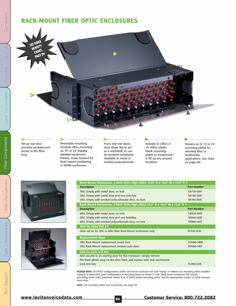
Fibe
r Com
pone
nts
Fibe
r Com
pone
nts
Cab
le M
anag
emen
tCab
le M
anag
emen
tTo
ols
& A
cces
sorie
sTo
ols
& A
cces
sorie
sCop
per
Com
pone
nts
Cop
per
Com
pone
nts
Wal
lpla
tes
& H
ousi
ngs
Wal
lpla
tes
& H
ousi
ngs
Con
nect
ors
Con
nect
ors
Tech
Sup
port
Tech
Sup
port
Customer Service: 800.722.2082www.levitonvoicedata.com D6
RARACK-MOUNT FIBER OPTIC ENCLOSURESCK-MOUNT FIBER OPTIC ENCLOSURES
3RU, Empty with metal door, no lock 5R730-00N
3RU, Empty with metal door and one lock/key 5R740-00N
3RU, Empty with smoked polycarbonate door, no lock 5R760-00N
Rack-Mount Enclosures, 3 Rack Units High (3RU) 5.25" H x 19.0" W x 12.0" D UDescription Part Number
6RU, Empty with metal door, no lock 5R930-00N
6RU, Empty with metal door and one lock/key 5R940-00N
6RU, Empty with smoked polycarbonate door, no lock 5R960-00N
Rack-Mount Enclosures, 6 Rack Units High (6RU) 10.5" H x 19.0" W x 12.0" D UDescription Part Number
Slide rail kit for 3RU or 6RU fiber Rack-Mount enclosures only 5S100-SLM
3RU Rack-Mount replacement metal door 5D000-3RM
3RU Rack-Mount replacement smoked poly door 5D000-3RP
Add-On Slide Rail Kit
Replacement Door
Add-on Lock and KeyAdd security to an existing door for this enclosure—simply remove
the black plastic plug on the door front, and replace with lock mechanism.
Lock and Key 5L000-LOK
A
C
B
Includes 8 (3RU) or16 (6RU) plasticblank mountingplates to inexpensive-ly fill up any unusedlocations.
Tilt-up rear doorprovides unobstructedaccess to the fiberloop.
Reversible mountingbrackets allow mountingon 19" or 23" industrystandard equipmentframes; move forward forflush mount positioningin NEMA enclosures.
Front and rear doorsdrop down flat to actas a workshelf, or canbe removed completely.Available in metal orsmoked polycarbonate.
CB
Houses up to 12 or 24mounting plates forassorted fiber ormultimediaapplications. See charton page D9.
A
PLEASE NOTE: All STOCK configurations of this rack-mount enclosure are sold ‘empty,’ or without any mounting plates installed.Capacity is dependent upon configuration of mounting plates as shown in note. Rack-mount enclosures DO includegrounding/strain relief, grommets, labels, 8 or 16 blank plastic mounting plates, and the appropriate number of cable manage-ment rings.
Note: For mounting plates and accessories, see page D9.
SEE FIBER
DENSITY
CHART,
PAGE D9
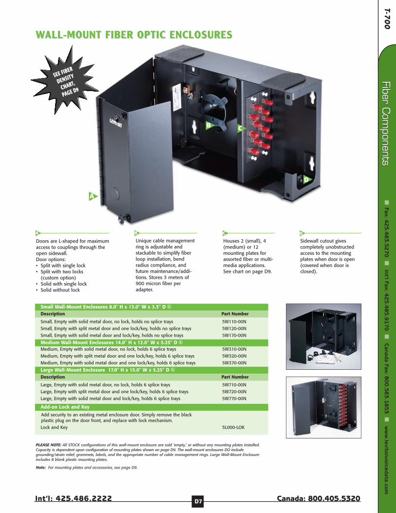
T-70
0
Int’l: 425.486.2222 Canada: 800.405.5320
Fiber Com
ponents
Fax: 42
5.4
83
.52
70
Int’l Fax: 4
25
.48
5.9
17
0
Canada Fax: 8
00
.56
3.1
85
3
ww
w.levitonvoicedata.com
Fiber Com
ponents
D7
D
CB
A
Doors are L-shaped for maximumaccess to couplings through theopen sidewall.Door options:• Split with single lock • Split with two locks
(custom option)• Solid with single lock• Solid without lock
Unique cable managementring is adjustable andstackable to simplify fiberloop installation, bendradius compliance, andfuture maintenance/addi-tions. Stores 3 meters of900 micron fiber peradapter.
Houses 2 (small), 4(medium) or 12mounting plates forassorted fiber or multi-media applications.See chart on page D9.
Sidewall cutout givescompletely unobstructedaccess to the mountingplates when door is open(covered when door isclosed).
DCA B
Small, Empty with solid metal door, no lock, holds no splice trays 5W110-00N
Small, Empty with split metal door and one lock/key, holds no splice trays 5W120-00N
Small, Empty with solid metal door and lock/key, holds no splice trays 5W170-00N
Small Wall-Mount Enclosures 8.0" H x 13.0" W x 3.5" D UDescription Part Number
Medium, Empty with solid metal door, no lock, holds 6 splice trays 5W310-00N
Medium, Empty with split metal door and one lock/key, holds 6 splice trays 5W320-00N
Medium, Empty with solid metal door and one lock/key, holds 6 splice trays 5W370-00N
Add security to an existing metal enclosure door. Simply remove the black plastic plug on the door front, and replace with lock mechanism.
Lock and Key 5L000-LOK
Medium Wall-Mount Enclosures 14.0" H x 12.0" W x 5.25" D U
Add-on Lock and Key
PLEASE NOTE: All STOCK configurations of this wall-mount enclosure are sold ‘empty,’ or without any mounting plates installed.Capacity is dependent upon configuration of mounting plates shown on page D9. The wall-mount enclosures DO includegrounding/strain relief, grommets, labels, and the appropriate number of cable management rings. Large Wall-Mount Enclosureincludes 8 blank plastic mounting plates.
Note: For mounting plates and accessories, see page D9.
Large, Empty with solid metal door, no lock, holds 6 splice trays 5W710-00N
Large, Empty with split metal door and one lock/key, holds 6 splice trays 5W720-00N
Large, Empty with solid metal door and lock/key, holds 6 splice trays 5W770-00N
Large Wall-Mount Enclosure 17.0" H x 15.0" W x 5.25" D UDescription Part Number
WWALL-MOUNT FIBER OPTIC ENCLOSURESALL-MOUNT FIBER OPTIC ENCLOSURES
SEE FIBER
DENSITY
CHART,
PAGE D9
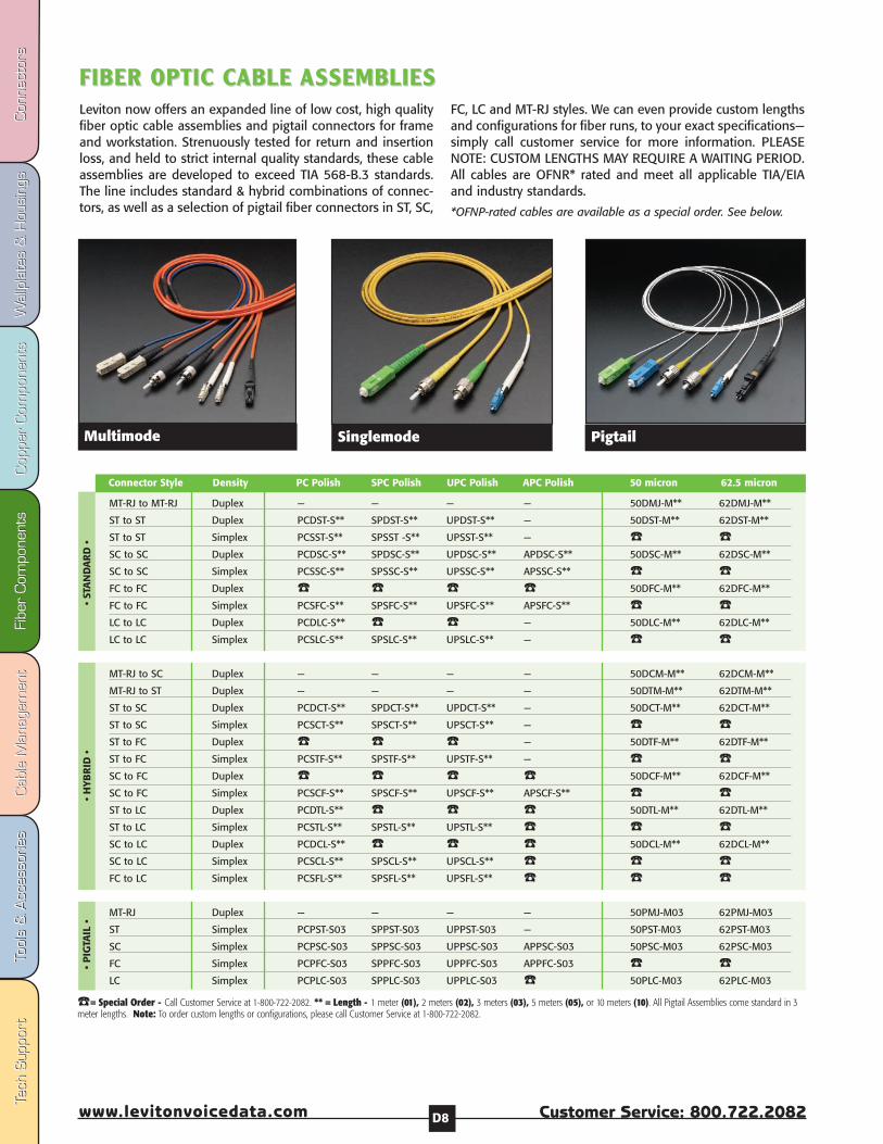
Fibe
r Com
pone
nts
Fibe
r Com
pone
nts
Cab
le M
anag
emen
tCab
le M
anag
emen
tTo
ols
& A
cces
sorie
sTo
ols
& A
cces
sorie
sCop
per
Com
pone
nts
Cop
per
Com
pone
nts
Wal
lpla
tes
& H
ousi
ngs
Wal
lpla
tes
& H
ousi
ngs
Con
nect
ors
Con
nect
ors
Tech
Sup
port
Tech
Sup
port
Customer Service: 800.722.2082www.levitonvoicedata.com D8
FIBER OPTIC CFIBER OPTIC CABLE ABLE ASSEMBLIESASSEMBLIESLeviton now offers an expanded line of low cost, high qualityfiber optic cable assemblies and pigtail connectors for frameand workstation. Strenuously tested for return and insertionloss, and held to strict internal quality standards, these cableassemblies are developed to exceed TIA 568-B.3 standards.The line includes standard & hybrid combinations of connec-tors, as well as a selection of pigtail fiber connectors in ST, SC,
FC, LC and MT-RJ styles. We can even provide custom lengthsand configurations for fiber runs, to your exact specifications—simply call customer service for more information. PLEASENOTE: CUSTOM LENGTHS MAY REQUIRE A WAITING PERIOD.All cables are OFNR* rated and meet all applicable TIA/EIAand industry standards.
*OFNP-rated cables are available as a special order. See below.
MT-RJ to MT-RJ Duplex — — — — 50DMJ-M** 62DMJ-M**
ST to ST Duplex PCDST-S** SPDST-S** UPDST-S** — 50DST-M** 62DST-M**
ST to ST Simplex PCSST-S** SPSST -S** UPSST-S** — SC to SC Duplex PCDSC-S** SPDSC-S** UPDSC-S** APDSC-S** 50DSC-M** 62DSC-M**
SC to SC Simplex PCSSC-S** SPSSC-S** UPSSC-S** APSSC-S** FC to FC Duplex 50DFC-M** 62DFC-M**
FC to FC Simplex PCSFC-S** SPSFC-S** UPSFC-S** APSFC-S** LC to LC Duplex PCDLC-S** — 50DLC-M** 62DLC-M**
LC to LC Simplex PCSLC-S** SPSLC-S** UPSLC-S** —
MT-RJ to SC Duplex — — — — 50DCM-M** 62DCM-M**
MT-RJ to ST Duplex — — — — 50DTM-M** 62DTM-M**
ST to SC Duplex PCDCT-S** SPDCT-S** UPDCT-S** — 50DCT-M** 62DCT-M**
ST to SC Simplex PCSCT-S** SPSCT-S** UPSCT-S** — ST to FC Duplex — 50DTF-M** 62DTF-M**
ST to FC Simplex PCSTF-S** SPSTF-S** UPSTF-S** — SC to FC Duplex 50DCF-M** 62DCF-M**
SC to FC Simplex PCSCF-S** SPSCF-S** UPSCF-S** APSCF-S** ST to LC Duplex PCDTL-S** 50DTL-M** 62DTL-M**
ST to LC Simplex PCSTL-S** SPSTL-S** UPSTL-S** SC to LC Duplex PCDCL-S** 50DCL-M** 62DCL-M**
SC to LC Simplex PCSCL-S** SPSCL-S** UPSCL-S** FC to LC Simplex PCSFL-S** SPSFL-S** UPSFL-S**
MT-RJ Duplex — — — — 50PMJ-M03 62PMJ-M03
ST Simplex PCPST-S03 SPPST-S03 UPPST-S03 — 50PST-M03 62PST-M03
SC Simplex PCPSC-S03 SPPSC-S03 UPPSC-S03 APPSC-S03 50PSC-M03 62PSC-M03
FC Simplex PCPFC-S03 SPPFC-S03 UPPFC-S03 APPFC-S03 LC Simplex PCPLC-S03 SPPLC-S03 UPPLC-S03 50PLC-M03 62PLC-M03
Connector Style Density PC Polish SPC Polish UPC Polish APC Polish 50 micron 62.5 micron
• ST
AN
DA
RD
••
HYB
RID
••
PIG
TAIL
•
= Special Order - Call Customer Service at 1-800-722-2082. ** = Length - 1 meter (01), 2 meters (02), 3 meters (03), 5 meters (05), or 10 meters (10). All Pigtail Assemblies come standard in 3meter lengths. Note: To order custom lengths or configurations, please call Customer Service at 1-800-722-2082.
Multimode Singlemode Pigtail
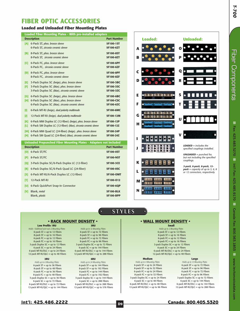
T-70
0
Int’l: 425.486.2222 Canada: 800.405.5320
Fiber Com
ponents
Fax: 42
5.4
83
.52
70
Int’l Fax: 4
25
.48
5.9
17
0
Canada Fax: 8
00
.56
3.1
85
3
ww
w.levitonvoicedata.com
Fiber Com
ponents
D9
FIBER OPTIC FIBER OPTIC AACCESSORIESCCESSORIESLoaded and Unloaded Fiber Mounting Plates
Loaded Fiber Mounting Plates - With pre-installed adapters
[A] 6-Pack ST, phos. bronze sleeve 5F100-1ST6-Pack ST, zirconia ceramic sleeve 5F100-6ZT
[B] 8-Pack ST, phos. bronze sleeve 5F100-8ST8-Pack ST, zirconia ceramic sleeve 5F100-8ZT
[C] 6-Pack FC, phos. bronze sleeve 5F100-6PF6-Pack FC, zirconia ceramic sleeve 5F100-6ZF
[D] 8-Pack FC, phos. bronze sleeve 5F100-8PF8-Pack FC, zirconia ceramic sleeve 5F100-8ZF
[E] 3-Pack Duplex SC (beige), phos. bronze sleeve 5F100-3BC[F] 3-Pack Duplex SC (blue), phos. bronze sleeve 5F100-3SC
3-Pack Duplex SC (blue), zirconia ceramic sleeve 5F100-3ZC
[G] 6-Pack Duplex SC (beige), phos. bronze sleeve 5F100-6BC[H] 6-Pack Duplex SC (blue), phos. bronze sleeve 5F100-CSC
6-Pack Duplex SC (blue), zirconia ceramic sleeve 5F100-6ZC
[I] 6-Pack MT-RJ (beige), dual polarity multimode 5F100-6MC
[J] 12-Pack MT-RJ (beige), dual polarity multimode 5F100-12M
[K] 6-Pack MM Duplex LC (12-fiber) (beige), phos. bronze sleeve 5F100-12P[L] 6-Pack SM Duplex LC (12-fiber) (blue), zirconia ceramic sleeve 5F100-12Z
[M] 6-Pack MM Quad LC (24-fiber) (beige), phos. bronze sleeve 5F100-24P[N] 6-Pack SM Quad LC (24-fiber) (blue), zirconia ceramic sleeve 5F100-24Z
Description Part Number
Unloaded Prepunched Fiber Mounting Plates - Adapters not included
[O] 6-Pack ST/FC 5F100-0ST
[P] 8-Pack ST/FC 5F100-NST
[Q] 3-Pack Duplex SC/6-Pack Duplex LC (12-fiber) 5F100-3CE
[R] 6-Pack Duplex SC/6-Pack Quad LC (24-fiber) 5F100-0SC
[S] 6-Pack MT-RJ/6-Pack Duplex LC (12-fiber) 5F100-OMT
[T] 12-Pack MT-RJ 5F100-O12
[U] 6-Pack QuickPort Snap-In Connector 5F100-6QP
[V] Blank, metal 5F100-BLKBlank, plastic 5F100-BPP
Description Part Number LOADED = includes thespecified couplings installed.
UNLOADED = punched for,but not including the specifiedcouplings.
3-pack, 6-pack, 8-pack, 12-pack = capacity of up to 3, 6, 8or 12 connectors, respectively.
A
B
C
D
G
L
K
J
I
H
N
M
P
O
U
V
E
F
Q
R
S
T
Loaded: Unloaded:
• WALL MOUNT DENSITY •• RACK MOUNT DENSITY •Low Profile 1RU
Holds 1 Bulkhead w/or w/o 2 Mounting Plates6-pack ST = up to 12 Fibers 8-pack ST = up to 16 Fibers6-pack FC = up to 12 Fibers 8-pack FC = up to 16 Fibers
3-pack Duplex SC = up to 12 Fibers6-pack SC = up to 24 Fibers
6-pack MT-RJ/DLC = up to 24 Fibers12-pack MT-RJ/QLC = up to 48 Fibers
2RUHolds up to 6 Mounting Plates
6-pack ST = up to 36 Fibers8-pack ST = up to 48 Fibers6-pack FC = up to 36 Fibers8-pack FC = up to 48 Fibers
3-pack Duplex SC = up to 36 Fibers6-pack SC = up to 72 Fibers
6-pack MT-RJ/DLC = up to 72 Fibers12-pack MT-RJ/QLC = up to 144 Fibers
3RUHolds up to 12 Mounting Plates
6-pack ST = up to 72 Fibers8-pack ST = up to 96 Fibers6-pack FC = up to 72 Fibers8-pack FC = up to 96 Fibers
3-pack Duplex SC = up to 72 Fibers6-pack SC = up to 144 Fibers
6-pack MT-RJ/DLC = up to 144 Fibers12-pack MT-RJ/QLC = up to 288 Fibers
6RUHolds up to 24 Mounting Plates
6-pack ST = up to 144 Fibers8-pack ST = up to 192 Fibers6-pack FC = up to 144 Fibers8-pack FC = up to 192 Fibers
3-pack Duplex SC = up to 144 Fibers6-pack SC = up to 288 Fibers
6-pack MT-RJ/DLC = up to 288 Fibers12-pack MT-RJ/QLC = up to 576 Fibers
SmallHolds up to 2 Mounting Plates
6-pack ST = up to 12 Fibers8-pack ST = up to 16 Fibers6-pack FC = up to 12 Fibers8-pack FC = up to 16 Fibers
3-pack Duplex SC = up to 12 Fibers6-pack SC = up to 24 Fibers
6-pack MT-RJ/DLC = up to 24 Fibers12-pack MT-RJ/QLC = up to 48 Fibers
MediumHolds up to 4 Mounting Plates
6-pack ST = up to 24 Fibers8-pack ST = up to 32 Fibers6-pack FC = up to 24 Fibers8-pack FC = up to 32 Fibers
3-pack Duplex SC = up to 24 Fibers6-pack SC = up to 48 Fibers
6-pack MT-RJ/DLC = up to 48 Fibers12-pack MT-RJ/QLC = up to 96 Fibers
LargeHolds up to 12 Mounting Plates
6-pack ST = up to 72 Fibers8-pack ST = up to 96 Fibers6-pack FC = up to 72 Fibers8-pack FC = up to 96 Fibers
3-pack Duplex SC = up to 72 Fibers6-pack SC = up to 144 Fibers
6-pack MT-RJ/DLC = up to 144 Fibers12-pack MT-RJ/QLC = up to 288 Fibers
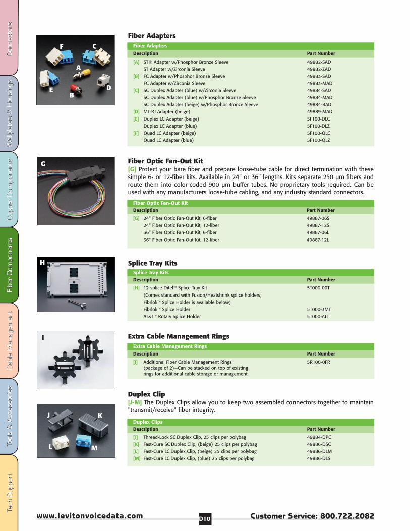
Fibe
r Com
pone
nts
Fibe
r Com
pone
nts
Cab
le M
anag
emen
tCab
le M
anag
emen
tTo
ols
& A
cces
sorie
sTo
ols
& A
cces
sorie
sCop
per
Com
pone
nts
Cop
per
Com
pone
nts
Wal
lpla
tes
& H
ousi
ngs
Wal
lpla
tes
& H
ousi
ngs
Con
nect
ors
Con
nect
ors
Tech
Sup
port
Tech
Sup
port
Customer Service: 800.722.2082www.levitonvoicedata.com D10
G
[G] 24" Fiber Optic Fan-Out Kit, 6-fiber 49887-06S
24" Fiber Optic Fan-Out Kit, 12-fiber 49887-12S
36" Fiber Optic Fan-Out Kit, 6-fiber 49887-06L
36" Fiber Optic Fan-Out Kit, 12-fiber 49887-12L
Fiber Optic Fan-Out KitDescription Part Number
Fiber Optic Fan-Out Kit[G] Protect your bare fiber and prepare loose-tube cable for direct termination with thesesimple 6- or 12-fiber kits. Available in 24" or 36" lengths. Kits separate 250 µm fibers androute them into color-coded 900 µm buffer tubes. No proprietary tools required. Can beused with any manufacturers loose-tube cabling, and any industry standard connectors.
Splice Tray KitsSplice Tray Kits
[H] 12-splice Ditel™ Splice Tray Kit 5T000-00T
(Comes standard with Fusion/Heatshrink splice holders;
Fibrlok™ Splice Holder is available below)
Fibrlok™ Splice Holder 5T000-3MT
AT&T™ Rotary Splice Holder 5T000-ATT
Description Part Number
Extra Cable Management RingsExtra Cable Management Rings
[I] Additional Fiber Cable Management Rings 5R100-0FR(package of 2)—Can be stacked on top of existing rings for additional cable storage or management.
Description Part Number
I
Duplex Clip[J-M] The Duplex Clips allow you to keep two assembled connectors together to maintain"transmit/receive" fiber integrity.
[J] Thread-Lock SC Duplex Clip, 25 clips per polybag 49884-DPC
[K] Fast-Cure SC Duplex Clip, (beige) 25 clips per polybag 49886-DSC
[L] Fast-Cure LC Duplex Clip, (beige) 25 clips per polybag 49886-DLM
[M] Fast-Cure LC Duplex Clip, (blue) 25 clips per polybag 49886-DLS
Duplex ClipsDescription Part Number
J
H
Fiber AdaptersFiber Adapters
[A] ST® Adapter w/Phosphor Bronze Sleeve 49882-SAD
ST Adapter w/Zirconia Sleeve 49882-ZAD
[B] FC Adapter w/Phosphor Bronze Sleeve 49883-SAD
FC Adapter w/Zirconia Sleeve 49883-MAD
[C] SC Duplex Adapter (blue) w/Zirconia Sleeve 49884-SAD
SC Duplex Adapter (blue) w/Phosphor Bronze Sleeve 49884-MAD
SC Duplex Adapter (beige) w/Phosphor Bronze Sleeve 49884-BAD
[D] MT-RJ Adapter (beige) 49889-MAD
[E] Duplex LC Adapter (beige) 5F100-DLC
Duplex LC Adapter (blue) 5F100-DLZ
[F] Quad LC Adapter (beige) 5F100-QLC
Quad LC Adapter (blue) 5F100-QLZ
Description Part Number
A
B
C
DE
F
K
ML

Slotted Duct Cable Management E3
Hook and Loop Cable Management E4
Rack Cable Management E5

Fibe
r Com
pone
nts
Fibe
r Com
pone
nts
Cab
le M
anag
emen
tCab
le M
anag
emen
tTo
ols
& A
cces
sorie
sTo
ols
& A
cces
sorie
sCop
per
Com
pone
nts
Cop
per
Com
pone
nts
Wal
lpla
tes
& H
ousi
ngs
Wal
lpla
tes
& H
ousi
ngs
Con
nect
ors
Con
nect
ors
Tech
Sup
port
Tech
Sup
port
Customer Service: 800.722.2082www.levitonvoicedata.com E2
1 2 3 4 5 67 8 9 10 11 12
13 14 15 16 17 1819 20 21 22 23 24
1 2 3 45
67 8 9 10 11 12
13 14 15 16 17 1819 20 21 22 23 24
25 26 27 28 29 3031 32 33 34 35 36
37 38 39 40 41 4243 44 45 46 47 48
1 2 3 4 5 67 8 9 10 11 12
13 14 15 16 17 1819 20 21 22 23 24
25 26 27 28 29 3031 32 33 34 35 36
37 38 39 40 41 4243 44 45 46 47 48
Vert
ical
Channel Divider
Duct
Cove
r Hinge
Cabl
eRe
tainer
Bend
-rad
iusCompliant Funnel
Slac
k Loop Storage Organizer
Bend
-radiu
s Compliant Router
Vertical Versi-Duct Components
Horizontal Versi-Duct Components
Versi-Duct Accessories
VERSI-DUCT™ SLOVERSI-DUCT™ SLOTTED DUCT TTED DUCT Route and protect fiber and copper cable with the Versi-Duct™Slotted Duct System from Leviton. Designed to fit on anystandard 19” equipment rack, this innovative slotted duct systemuses a small number of accessories to achieve a wide range ofcable management solutions.
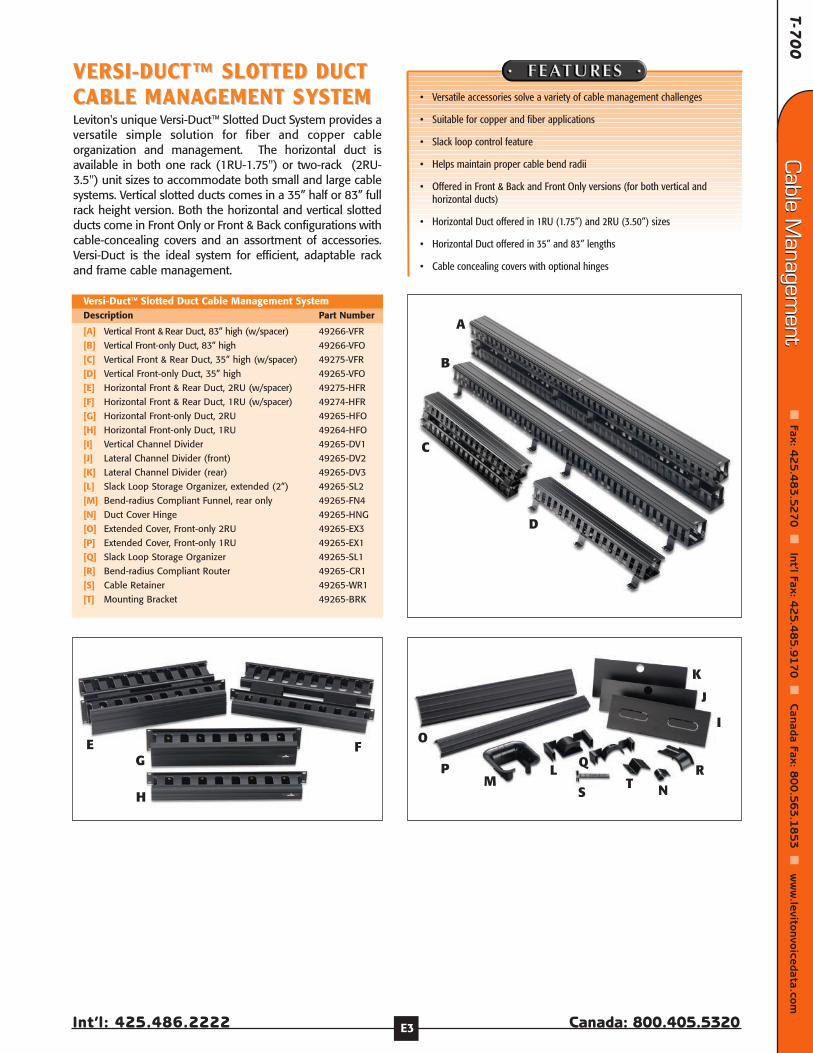
T-70
0
Int’l: 425.486.2222 Canada: 800.405.5320
Cable M
anagement
Fax: 4
25
.48
3.5
27
0
Int’l Fax: 42
5.4
85
.91
70
C
anada Fax: 80
0.5
63
.18
53
w
ww
.levitonvoicedata.comCable M
anagement
E3
VERSI-DUCT™ SLOVERSI-DUCT™ SLOTTED DUCTTTED DUCTCCABLE MANAABLE MANAGEMENT SYGEMENT SYSTEMSTEMLeviton's unique Versi-Duct™ Slotted Duct System provides aversatile simple solution for fiber and copper cableorganization and management. The horizontal duct isavailable in both one rack (1RU-1.75") or two-rack (2RU-3.5") unit sizes to accommodate both small and large cablesystems. Vertical slotted ducts comes in a 35” half or 83” fullrack height version. Both the horizontal and vertical slottedducts come in Front Only or Front & Back configurations withcable-concealing covers and an assortment of accessories.Versi-Duct is the ideal system for efficient, adaptable rackand frame cable management.
[A] Vertical Front & Rear Duct, 83” high (w/spacer) 49266-VFR
[B] Vertical Front-only Duct, 83” high 49266-VFO
[C] Vertical Front & Rear Duct, 35” high (w/spacer) 49275-VFR
[D] Vertical Front-only Duct, 35” high 49265-VFO
[E] Horizontal Front & Rear Duct, 2RU (w/spacer) 49275-HFR
[F] Horizontal Front & Rear Duct, 1RU (w/spacer) 49274-HFR
[G] Horizontal Front-only Duct, 2RU 49265-HFO
[H] Horizontal Front-only Duct, 1RU 49264-HFO
[I] Vertical Channel Divider 49265-DV1
[J] Lateral Channel Divider (front) 49265-DV2
[K] Lateral Channel Divider (rear) 49265-DV3
[L] Slack Loop Storage Organizer, extended (2”) 49265-SL2
[M] Bend-radius Compliant Funnel, rear only 49265-FN4
[N] Duct Cover Hinge 49265-HNG
[O] Extended Cover, Front-only 2RU 49265-EX3
[P] Extended Cover, Front-only 1RU 49265-EX1
[Q] Slack Loop Storage Organizer 49265-SL1
[R] Bend-radius Compliant Router 49265-CR1
[S] Cable Retainer 49265-WR1
[T] Mounting Bracket 49265-BRK
Versi-Duct™ Slotted Duct Cable Management SystemDescription Part Number
• Versatile accessories solve a variety of cable management challenges
• Suitable for copper and fiber applications
• Slack loop control feature
• Helps maintain proper cable bend radii
• Offered in Front & Back and Front Only versions (for both vertical andhorizontal ducts)
• Horizontal Duct offered in 1RU (1.75”) and 2RU (3.50”) sizes
• Horizontal Duct offered in 35” and 83” lengths
• Cable concealing covers with optional hinges
A
B
C
E FG
H
D
I
J
K
O
PM
L
S
Q
T NR
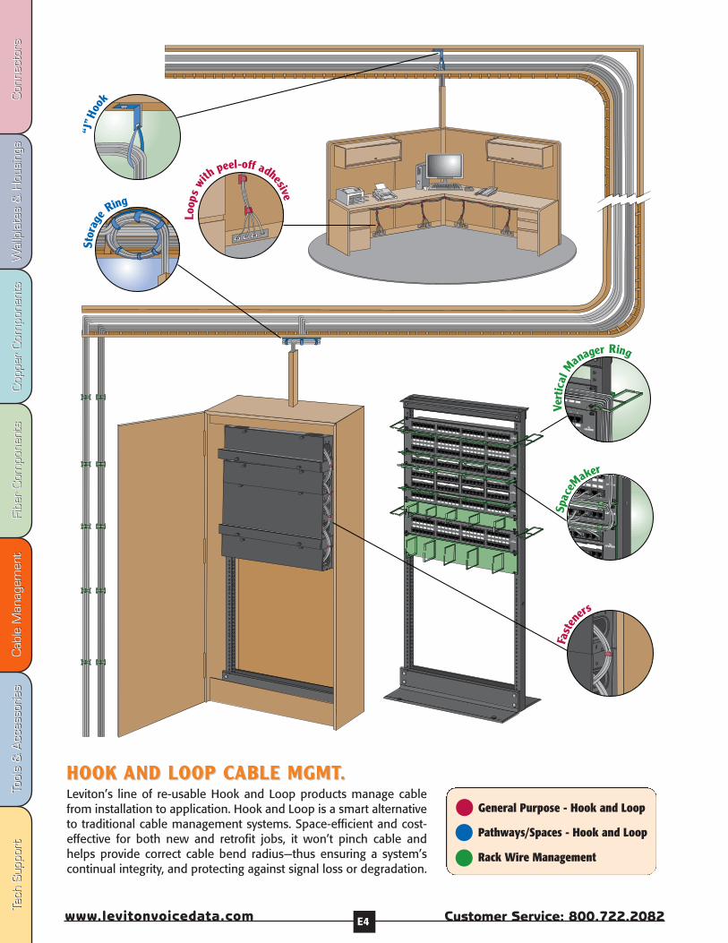
Fibe
r Com
pone
nts
Fibe
r Com
pone
nts
Cab
le M
anag
emen
tCab
le M
anag
emen
tTo
ols
& A
cces
sorie
sTo
ols
& A
cces
sorie
sCop
per
Com
pone
nts
Cop
per
Com
pone
nts
Wal
lpla
tes
& H
ousi
ngs
Wal
lpla
tes
& H
ousi
ngs
Con
nect
ors
Con
nect
ors
Tech
Sup
port
Tech
Sup
port
Customer Service: 800.722.2082www.levitonvoicedata.com E4
1 2 3 4 5 67 8 9 10 11 12
13 14 15 16 17 1819 20 21 22 23 24
1 2 3 45
67 8 9 10 11 12
13 14 15 16 17 1819 20 21 22 23 24
25 26 27 28 29 3031 32 33 34 35 36
37 38 39 40 41 4243 44 45 46 47 48
12
3 45
67
89 10 11 12
13 14 15 16 17 1819 20
21 22 23 24
12
34
56
78
910
11 12 13 14
15 1617 18
19 2021 22 23
2425 26 27 28 2930
31 32 33 3435 36
37 38 39 4041 42
43 44 45 4647 48
2 23 24
46 4
2 23 24
43 44 45 46 47 48
“J”H
ook
Stor
age RingLo
ops
wi
thpeel-off adhesive
Vert
ical
Manager Ring
Fast
en
ers
Spac
eMaker
General Purpose - Hook and Loop
Pathways/Spaces - Hook and Loop
Rack Wire Management
HOOK HOOK AND LOOP CAND LOOP CABLE MGMTABLE MGMT..Leviton’s line of re-usable Hook and Loop products manage cablefrom installation to application. Hook and Loop is a smart alternativeto traditional cable management systems. Space-efficient and cost-effective for both new and retrofit jobs, it won’t pinch cable andhelps provide correct cable bend radius—thus ensuring a system’scontinual integrity, and protecting against signal loss or degradation.
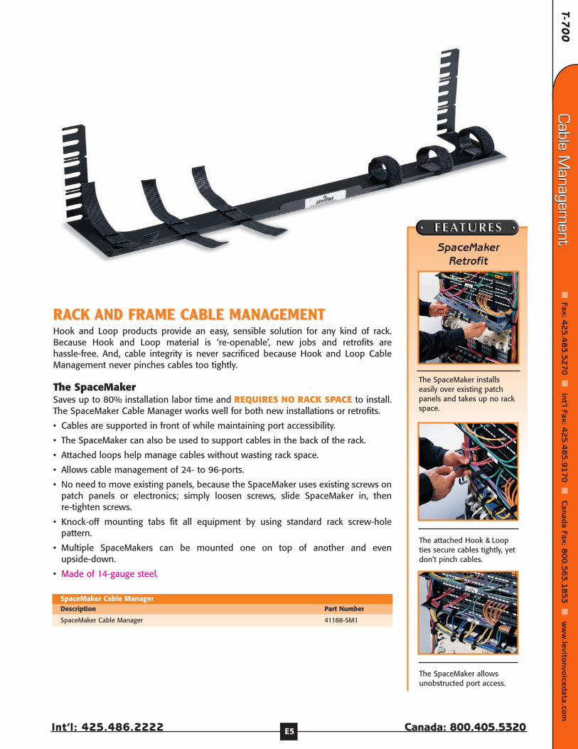
T-70
0
Int’l: 425.486.2222 Canada: 800.405.5320
Cable M
anagement
Fax: 4
25
.48
3.5
27
0
Int’l Fax: 42
5.4
85
.91
70
C
anada Fax: 80
0.5
63
.18
53
w
ww
.levitonvoicedata.comCable M
anagement
E5
RARACK CK AND FRAME CAND FRAME CABLE MANAABLE MANAGEMENTGEMENTHook and Loop products provide an easy, sensible solution for any kind of rack.Because Hook and Loop material is ‘re-openable’, new jobs and retrofits arehassle-free. And, cable integrity is never sacrificed because Hook and Loop CableManagement never pinches cables too tightly.
The SpaceMakerSaves up to 80% installation labor time and REQUIRES NO RACK SPACE to install.The SpaceMaker Cable Manager works well for both new installations or retrofits.
• Cables are supported in front of while maintaining port accessibility.
• The SpaceMaker can also be used to support cables in the back of the rack.
• Attached loops help manage cables without wasting rack space.
• Allows cable management of 24- to 96-ports.
• No need to move existing panels, because the SpaceMaker uses existing screws onpatch panels or electronics; simply loosen screws, slide SpaceMaker in, thenre-tighten screws.
• Knock-off mounting tabs fit all equipment by using standard rack screw-holepattern.
• Multiple SpaceMakers can be mounted one on top of another and evenupside-down.
• Made of 14-gauge steel.
SpaceMaker Retrofit
The SpaceMaker installseasily over existing patchpanels and takes up no rackspace.
The attached Hook & Loopties secure cables tightly, yetdon’t pinch cables.
The SpaceMaker allowsunobstructed port access.
SpaceMaker Cable Manager 41188-SM1
SpaceMaker Cable ManagerDescription Part Number
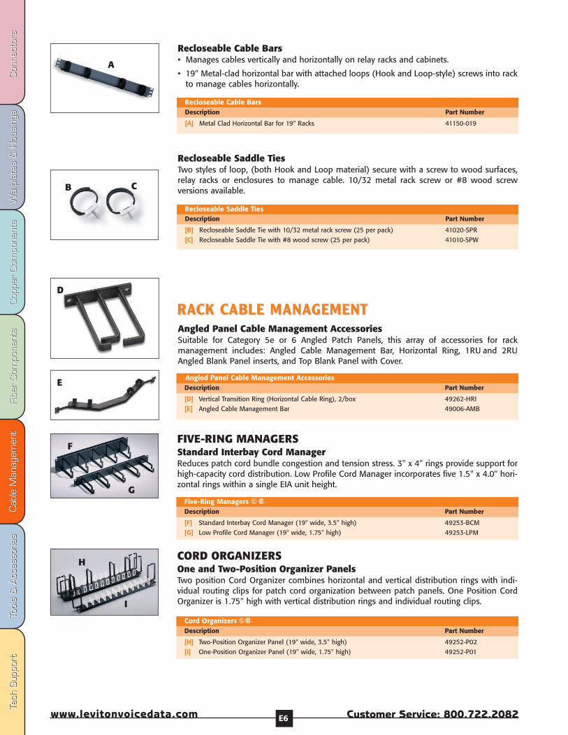
Fibe
r Com
pone
nts
Fibe
r Com
pone
nts
Cab
le M
anag
emen
tCab
le M
anag
emen
tTo
ols
& A
cces
sorie
sTo
ols
& A
cces
sorie
sCop
per
Com
pone
nts
Cop
per
Com
pone
nts
Wal
lpla
tes
& H
ousi
ngs
Wal
lpla
tes
& H
ousi
ngs
Con
nect
ors
Con
nect
ors
Tech
Sup
port
Tech
Sup
port
Customer Service: 800.722.2082www.levitonvoicedata.com E6
Recloseable Cable Bars• Manages cables vertically and horizontally on relay racks and cabinets.
• 19" Metal-clad horizontal bar with attached loops (Hook and Loop-style) screws into rackto manage cables horizontally.
Recloseable Saddle TiesTwo styles of loop, (both Hook and Loop material) secure with a screw to wood surfaces,relay racks or enclosures to manage cable. 10/32 metal rack screw or #8 wood screwversions available.
[B] Recloseable Saddle Tie with 10/32 metal rack screw (25 per pack) 41020-SPR
[C] Recloseable Saddle Tie with #8 wood screw (25 per pack) 41010-SPW
Recloseable Saddle TiesDescription Part Number
[A] Metal Clad Horizontal Bar for 19" Racks 41150-019
Recloseable Cable BarsDescription Part Number
B C
A
[D] Vertical Transition Ring (Horizontal Cable Ring), 2/box 49262-HRI
[E] Angled Cable Management Bar 49006-AMB
Angled Panel Cable Management AccessoriesDescription Part Number
RARACK CCK CABLE MANAABLE MANAGEMENT GEMENT Angled Panel Cable Management AccessoriesSuitable for Category 5e or 6 Angled Patch Panels, this array of accessories for rackmanagement includes: Angled Cable Management Bar, Horizontal Ring, 1RU and 2RUAngled Blank Panel inserts, and Top Blank Panel with Cover.
D
E
FIVE-RING MANAGERSStandard Interbay Cord ManagerReduces patch cord bundle congestion and tension stress. 3" x 4" rings provide support forhigh-capacity cord distribution. Low Profile Cord Manager incorporates five 1.5" x 4.0" hori-zontal rings within a single EIA unit height.
[F] Standard Interbay Cord Manager (19" wide, 3.5" high) 49253-BCM
[G] Low Profile Cord Manager (19" wide, 1.75" high) 49253-LPM
Five-Ring Managers USDescription Part Number
[H] Two-Position Organizer Panel (19" wide, 3.5" high) 49252-P02
[I] One-Position Organizer Panel (19" wide, 1.75" high) 49252-P01
Cord Organizers USDescription Part Number
F
G
H
I
CORD ORGANIZERSOne and Two-Position Organizer PanelsTwo position Cord Organizer combines horizontal and vertical distribution rings with indi-vidual routing clips for patch cord organization between patch panels. One Position CordOrganizer is 1.75" high with vertical distribution rings and individual routing clips.
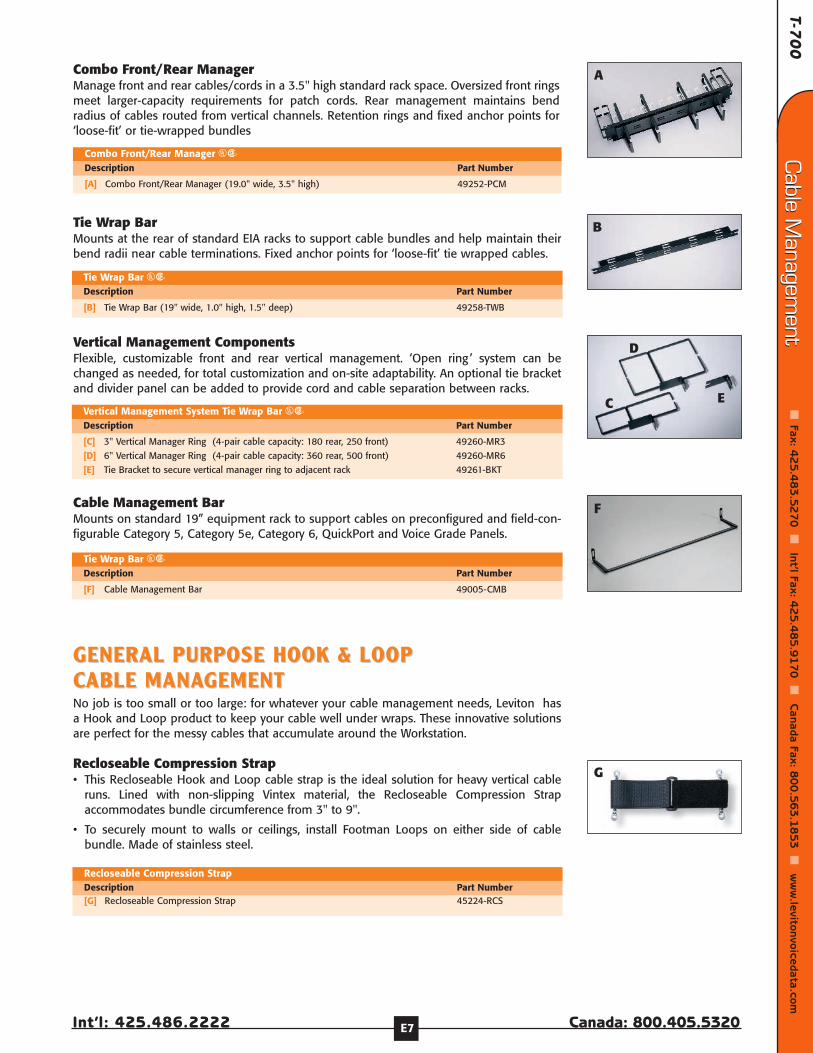
T-70
0
Int’l: 425.486.2222 Canada: 800.405.5320
Cable M
anagement
Fax: 4
25
.48
3.5
27
0
Int’l Fax: 42
5.4
85
.91
70
C
anada Fax: 80
0.5
63
.18
53
w
ww
.levitonvoicedata.comCable M
anagement
E7
GENERAL PURPOSE HOOK & LOOP GENERAL PURPOSE HOOK & LOOP CCABLE MANAABLE MANAGEMENTGEMENTNo job is too small or too large: for whatever your cable management needs, Leviton hasa Hook and Loop product to keep your cable well under wraps. These innovative solutionsare perfect for the messy cables that accumulate around the Workstation.
Recloseable Compression Strap• This Recloseable Hook and Loop cable strap is the ideal solution for heavy vertical cable
runs. Lined with non-slipping Vintex material, the Recloseable Compression Strapaccommodates bundle circumference from 3" to 9".
• To securely mount to walls or ceilings, install Footman Loops on either side of cablebundle. Made of stainless steel.
[G] Recloseable Compression Strap 45224-RCS
Recloseable Compression StrapDescription Part Number
G
[A] Combo Front/Rear Manager (19.0" wide, 3.5" high) 49252-PCM
Combo Front/Rear Manager USDescription Part Number
[B] Tie Wrap Bar (19" wide, 1.0" high, 1.5" deep) 49258-TWB
Tie Wrap Bar USDescription Part Number
[C] 3" Vertical Manager Ring (4-pair cable capacity: 180 rear, 250 front) 49260-MR3
[D] 6" Vertical Manager Ring (4-pair cable capacity: 360 rear, 500 front) 49260-MR6
[E] Tie Bracket to secure vertical manager ring to adjacent rack 49261-BKT
Vertical Management System Tie Wrap Bar USDescription Part Number
A
B
D
C E
Vertical Management ComponentsFlexible, customizable front and rear vertical management. ‘Open ring ’ system can bechanged as needed, for total customization and on-site adaptability. An optional tie bracketand divider panel can be added to provide cord and cable separation between racks.
Combo Front/Rear ManagerManage front and rear cables/cords in a 3.5" high standard rack space. Oversized front ringsmeet larger-capacity requirements for patch cords. Rear management maintains bendradius of cables routed from vertical channels. Retention rings and fixed anchor points for‘loose-fit’ or tie-wrapped bundles
Tie Wrap BarMounts at the rear of standard EIA racks to support cable bundles and help maintain theirbend radii near cable terminations. Fixed anchor points for ‘loose-fit’ tie wrapped cables.
[F] Cable Management Bar 49005-CMB
Tie Wrap Bar USDescription Part Number
Cable Management BarMounts on standard 19” equipment rack to support cables on preconfigured and field-con-figurable Category 5, Category 5e, Category 6, QuickPort and Voice Grade Panels.
F

Fibe
r Com
pone
nts
Fibe
r Com
pone
nts
Cab
le M
anag
emen
tCab
le M
anag
emen
tTo
ols
& A
cces
sorie
sTo
ols
& A
cces
sorie
sCop
per
Com
pone
nts
Cop
per
Com
pone
nts
Wal
lpla
tes
& H
ousi
ngs
Wal
lpla
tes
& H
ousi
ngs
Con
nect
ors
Con
nect
ors
Tech
Sup
port
Tech
Sup
port
Customer Service: 800.722.2082www.levitonvoicedata.com E8
Recloseable Storage RingsEnsure fiber optic cable bend radius with the Recloseable Storage Ring. Available in twosizes for inside or outside fiber cable management, both rings come complete with six stur-dy Hook and Loop-style loops attached for proper cable management.
• The Outside Plant Ring is 24" in diameter and manages cable as it enters a premises. It iscapable of storing excess cable for future use.
• The Inside Plant Ring is 11.75" in diameter and mounts neatly into a ceiling or wall tostore extra fiber optic cable for future use.
Hook and Loop Workstation Cable ManagementThese Hook and Loop tie-wraps are ideal for workstation cable management. Hook andLoop material easily reopens for moves, adds and changes. Eliminate tangled wiring in thework area by managing power cords and equipment cords singly or bundled together.Convenient peel-off adhesive for easy mounting. 5.25” loop.
Recloseable Orange Hook and Loop FastenersSimilar to Recloseable Tie-Wraps, these sturdy loops also hold cable bundles up to 3" indiameter, but come in bright orange for use with fiber cables. Fasteners are 3/4" wide.
Bulk Rolls of Hook and Loop WrapAvailable in 15 and 75 foot rolls, 1/2" wide, which can be custom cut for many uses, andfeatures hook and loop material on both sides.
[E] Recloseable Storage Ring, Inside Plant (11.75" diameter) 48900-IFR
Recloseable Storage Ring, Outside Plant (24” diameter) 48900-OFR
Recloseable Storage RingsDescription Part Number
[F] Individual Loops with Peel-off Adhesive (25 per pack) 41225-SAP
Hook and Loop Workstation Cable ManagementDescription Part Number
[G] Recloseable Fasteners (orange) (10 per pack) 41030-0FT
Recloseable FastenerDescription Part Number
[H] Bulk Hook and Loop Wrap, 15 Foot Roll 43115-015
[I] Bulk Hook and Loop Wrap, 75 Foot Roll 43115-075
Bulk Hook and Loop WrapDescription Part Number
E
F
G
I H
[B] Tie Wrap, 5" Length (25 per pack) 43105-005
[C] Tie Wrap, 8" Length (25 per pack) 43108-008
[D] Tie Wrap, 12" Length (25 per pack) 43112-012
Recloseable Tie-WrapsDescription Part Number
BC
D
Recloseable Tie-WrapsA Hook and Loop tie-wrap that easily reopens for moves, adds and changes, this generalpurpose Hook and Loop strap is available in 5", 8" and 12" lengths 0.50” width.
[A] Recloseable “J” Hook 46700-SLG
Recloseable “J”-HookDescription Part Number
A Recloseable “J”-HookThis convenient Hook and Loop-style “J”-hook is height-adjustable to bypass ductwork andother construction obstacles in ceilings. Adjustable circumference opens up to8" diameter.
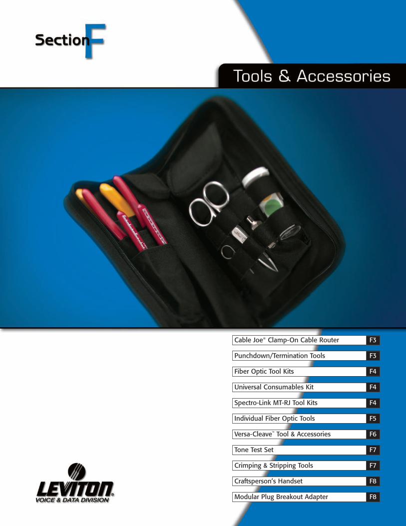
Cable Joe® Clamp-On Cable Router F3
Punchdown/Termination Tools F3
Fiber Optic Tool Kits F4
Universal Consumables Kit F4
Spectro-Link MT-RJ Tool Kits F4
Individual Fiber Optic Tools F5
Versa-Cleave™ Tool & Accessories F6
Tone Test Set F7
Crimping & Stripping Tools F7
Craftsperson’s Handset F8
Modular Plug Breakout Adapter F8
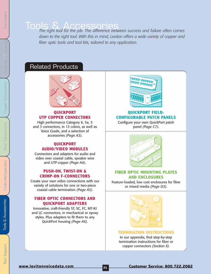
Fibe
r Com
pone
nts
Fibe
r Com
pone
nts
Cab
le M
anag
emen
tCab
le M
anag
emen
tTo
ols
& A
cces
sorie
sTo
ols
& A
cces
sorie
sCop
per
Com
pone
nts
Cop
per
Com
pone
nts
Wal
lpla
tes
& H
ousi
ngs
Wal
lpla
tes
& H
ousi
ngs
Con
nect
ors
Con
nect
ors
Tech
Sup
port
Tech
Sup
port
Customer Service: 800.722.2082www.levitonvoicedata.com F2
Related Products
QUICKPORT QUICKPORT UTPUTP COPPER CONNECTCOPPER CONNECTORSORS
High performance Category 6, 5e, 5 and 3 connectors, in 13 colors, as well as
Voice Grade, and a selection of accessories (Page A3).
QUICKPORT QUICKPORT AAUDIO/VIDEO MODULESUDIO/VIDEO MODULES
Connectors and adapters for audio and video over coaxial cable, speaker wire
and UTP copper (Page A4).
PUSH-ON,PUSH-ON, TWISTTWIST-ON & -ON & CRIMP-ON F-CONNECTCRIMP-ON F-CONNECTORSORS
Create your own video connections with ourvariety of solutions for one or two-piece
coaxial cable termination (Page A5).
FIBER OPTIC CONNECTFIBER OPTIC CONNECTORS ORS ANDANDQUICKPORT QUICKPORT ADADAPTERSAPTERS
Innovative, craft-friendly ST, SC, FC, MT-RJand LC connectors, in mechanical or epoxy
styles. Plus adapters to fit them to anyQuickPort housing (Page A6).
Tools & AccessoriesThe right tool for the job. The difference between success and failure often comesdown to the right tool. With this in mind, Leviton offers a wide variety of copper andfiber optic tools and tool kits, tailored to any application.
QUICKPORT FIELD-QUICKPORT FIELD-CONFIGURABLE PCONFIGURABLE PAATCH PTCH PANELSANELSConfigure your own QuickPort patch
panel (Page C7).
FIBER OPTIC MOUNTING PLAFIBER OPTIC MOUNTING PLATESTESAND ENCLOSURESAND ENCLOSURES
Feature-loaded, low cost enclosures for fiberor mixed media (Page D3).
TERMINATERMINATION INSTRUCTIONSTION INSTRUCTIONSIn our appendix, find step-by-step termination instructions for fiber or
copper connectors (Section X).

T-70
0
Int’l: 425.486.2222 Canada: 800.405.5320
Tools & A
ccessories
Fax: 42
5.4
83
.52
70
Int’l Fax: 4
25
.48
5.9
17
0
Canada Fax: 8
00
.56
3.1
85
3
ww
w.levitonvoicedata.com
Tools & A
ccessories
F3
[A] Cable Joe Clamp-on Cable Router 49001-JOE
Cable Joe®
Description Part Number
CCABLE JOEABLE JOE®® CLAMP-ON CCLAMP-ON CABLE ROUTERABLE ROUTER[A] The best solution available for pulling cables around corners.
• Saves time and money by preventing cable damage, and allowing moreeffective use of installation personnel.
• Mounts onto any surface: trays, joists, or lag bolts to walls.
• Routes up to 20 cables at once–even around 90° angles.
• Made of heavy duty 12 gauge cold rolled steel with 6-roller design to pullcables smoothly and easily.
• Opens simply and closes securely with quick-release pin.
Clamp or screw to stablestructure. Close and set latchbefore pulling cable.
When running cable arounda 90˚ corner, place Cable Joeat an angle, so that cableruns smoothly throughrollers.
If cable is being run aroundan angle that is tighter than90˚...
...use two Cable Joes torelieve cable stress.
IF CABLE PATH ISTIGHTER THAN 90˚
Position Cable Joe so that cables run at the widest angle possible. This will preserve cable bend radius.
Feed PullPull Pull
Pull
110 PUNCHDO110 PUNCHDOWN WN TTOOLOOL
Wire Punchdown/Termination Tool[B] A versatile punchdown/termination tool with changeable blades (sold separately) thatenables installers to make reliable connections on a variety of wire termination blocks.Terminate/punch down wire with one simple push on the handle. An adjustable impactsetting allows you to terminate wire with less effort than other impact tools. Handle can befitted with several interchangeable custom blades to cover many termination types: 110 IDC,66 IDC, Krone, BIX (Northern Telecom BIX system), and an awl (woodscrew starter punch).A spare blade can be kept in a storage chamber in the handle.
Punchdown Tool Blades[C-G] These special application blades are for use with the Wire Punchdown Tool forterminating 22, 24 or 26 gauge wire. Krone and BIX blades feature scissor-action trimming.
[B] Wire Punchdown/Termination Tool 49553-814
[C] 110 IDC Blade 49553-110
[D] 66-IDC Blade 49553-66
[E] BIX® Blade 49553-BIX
[F] Krone® Blade 49553-KRN
[G] Awl (Woodscrew starter punch) 49553-AWL
D814 Wire Punchdown/Termination Tool and D814 Tool BladesDescription Part Number
B
C
D
E
F
G
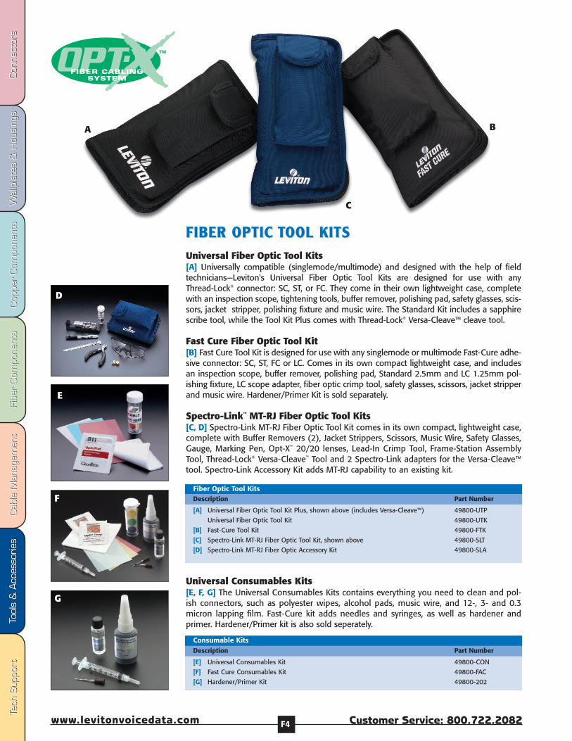
Fibe
r Com
pone
nts
Fibe
r Com
pone
nts
Cab
le M
anag
emen
tCab
le M
anag
emen
tTo
ols
& A
cces
sorie
sTo
ols
& A
cces
sorie
sCop
per
Com
pone
nts
Cop
per
Com
pone
nts
Wal
lpla
tes
& H
ousi
ngs
Wal
lpla
tes
& H
ousi
ngs
Con
nect
ors
Con
nect
ors
Tech
Sup
port
Tech
Sup
port
Customer Service: 800.722.2082www.levitonvoicedata.com F4
[E] Universal Consumables Kit 49800-CON
[F] Fast Cure Consumables Kit 49800-FAC
[G] Hardener/Primer Kit 49800-202
Consumable KitsDescription Part Number
E
Universal Consumables Kits[E, F, G] The Universal Consumables Kits contains everything you need to clean and pol-ish connectors, such as polyester wipes, alcohol pads, music wire, and 12-, 3- and 0.3micron lapping film. Fast-Cure kit adds needles and syringes, as well as hardener andprimer. Hardener/Primer kit is also sold seperately.
[A] Universal Fiber Optic Tool Kit Plus, shown above (includes Versa-Cleave™) 49800-UTP
Universal Fiber Optic Tool Kit 49800-UTK
[B] Fast-Cure Tool Kit 49800-FTK
[C] Spectro-Link MT-RJ Fiber Optic Tool Kit, shown above 49800-SLT
[D] Spectro-Link MT-RJ Fiber Optic Accessory Kit 49800-SLA
Fiber Optic Tool KitsDescription Part Number
A
D
G
F
FIBER OPTIC FIBER OPTIC TTOOL KITSOOL KITSUniversal Fiber Optic Tool Kits[A] Universally compatible (singlemode/multimode) and designed with the help of fieldtechnicians—Leviton's Universal Fiber Optic Tool Kits are designed for use with anyThread-Lock® connector: SC, ST, or FC. They come in their own lightweight case, completewith an inspection scope, tightening tools, buffer remover, polishing pad, safety glasses, scis-sors, jacket stripper, polishing fixture and music wire. The Standard Kit includes a sapphirescribe tool, while the Tool Kit Plus comes with Thread-Lock® Versa-Cleave™ cleave tool.
Fast Cure Fiber Optic Tool Kit [B] Fast Cure Tool Kit is designed for use with any singlemode or multimode Fast-Cure adhe-sive connector: SC, ST, FC or LC. Comes in its own compact lightweight case, and includesan inspection scope, buffer remover, polishing pad, Standard 2.5mm and LC 1.25mm pol-ishing fixture, LC scope adapter, fiber optic crimp tool, safety glasses, scissors, jacket stripperand music wire. Hardener/Primer Kit is sold separately.
Spectro-Link™ MT-RJ Fiber Optic Tool Kits [C, D] Spectro-Link MT-RJ Fiber Optic Tool Kit comes in its own compact, lightweight case,complete with Buffer Removers (2), Jacket Strippers, Scissors, Music Wire, Safety Glasses,Gauge, Marking Pen, Opt-X™ 20/20 lenses, Lead-In Crimp Tool, Frame-Station AssemblyTool, Thread-Lock® Versa-Cleave™ Tool and 2 Spectro-Link adapters for the Versa-Cleave™tool. Spectro-Link Accessory Kit adds MT-RJ capability to an existing kit.
C
B

T-70
0
Int’l: 425.486.2222 Canada: 800.405.5320
Tools & A
ccessories
Fax: 42
5.4
83
.52
70
Int’l Fax: 4
25
.48
5.9
17
0
Canada Fax: 8
00
.56
3.1
85
3
ww
w.levitonvoicedata.com
Tools & A
ccessories
F5
Description Part Number[A] Universal Tools
250 micron Buffer Remover 49886-BR2
Jacket Stripper 49886-STP
900 micron Buffer Remover 49886-BR9
Aramid Strand Scissors 49886-SIS
Marking Pen 49886-SMP
200x Inspection Scope 49886-FSP
100x Inspection Scope 49886-SCP
Safety Glasses 49886-GLS
Sapphire Scribe 49886-SCR
2.5mm Polishing Puck 49886-PUC
3” x 6” Polishing Pad 49886-PAD
Thread-Lock FC Tightening Tool 49883-FCT
Thread-Lock Combination SC/ST Tightening Tool 49886-CTT
Universal Tool-Kit Carrying Case 49886-CSC
[B] Spectro-Link Specific ToolsStrip Length Gauge 49886-SLG
Frame-Station Connector Assembly Tool 49886-FIT
Workstation Connector Lead-in Crimp Tool 49886-SLC
Versa-Cleave Adapter for Spectro-Link MT-RJ Workstation Connectors 49886-VWA
Versa-Cleave Adapter for Spectro-Link MT-RJ Frame-Station Connectors 49886-VFA
Opt-X 20/20 Lenses 49886-OTT
Spectro-Link Carrying Case 49886-CST
Spectro-Link Accessory Kit Carrying Case 49886-CSA
[C] Fast-Cure Specific ToolsFiber Optic Crimp Tool with .128, .151, .178 hex die 49886-FCT
LC Scope Adapter 49886-LCS
1.25mm (LC) Polishing Puck 49886-LCP
Fast Cure Tool Kit Carrying Case 49886-FCC
[D] ConsumablesMusic Wire 49886-WRE
Lint Free Dry Wipes 100/pack 49886-DWP
Alcohol Pads 100/pack 49886-APD
12- Micron Aluminum Oxide Lapping Film, 100/pack 49886-12F
3- Micron Aluminum Oxide Lapping Film, 100/pack 49886-03F
0.3 Micron Aluminum Oxide Lapping Film, 100/pack 49886-X3F
SC Duplex Clip (sold in increments of 25, bag of 25) 49884-DPC
Silicone BUS Kit (one of each type of BUS) 49885-SBS
Replacement Needles 25/pack 49886-FCN
Replacement Syringes 25/pack 49886-SYR
Individual Components
Individually Sold Fiber Optic Tools & Components
Tightening Tools[E,F] Available in two styles, FC and Combination SC/ST, tightening tools help simplifyThread-Lock connectorization by providing a wider gripping area to make it easier totighten the connector plug. The tightening tools also protect the exposed fiber during thetightening process. The Combination tightening tool has an SC-style end and an ST-styleend, for greater convenience and flexibility.
[E] ST/SC Combination Tightening Tool 49886-CTT
[F] FC Tightening Tool 49883-FCT
Tightening ToolsDescription Part Number
E
F
A
B
C
D

Fibe
r Com
pone
nts
Fibe
r Com
pone
nts
Cab
le M
anag
emen
tCab
le M
anag
emen
tTo
ols
& A
cces
sorie
sTo
ols
& A
cces
sorie
sCop
per
Com
pone
nts
Cop
per
Com
pone
nts
Wal
lpla
tes
& H
ousi
ngs
Wal
lpla
tes
& H
ousi
ngs
Con
nect
ors
Con
nect
ors
Tech
Sup
port
Tech
Sup
port
Customer Service: 800.722.2082www.levitonvoicedata.com F6
Inspection Scopes[E, F] Leviton’s 100x and 200x Inspection Scopes allow techs to view multimode and sin-glemode end-face polishes safely, and reduce the chances of over-polishing (a side-effectof many coaxial inspection scopes). 200x Scope features oblique viewing technology,ergonomic grip, 200X magnification and full laser eye protection through wavelengths of850-1550 nanometer. Both scopes feature rugged construction that stands up to jobsiteabuse.
[E] 100x Inspection Scope 49886-SCP
[F] 200x Inspection Scope 49886-FSP
Inspection ScopesDescription Part Number
D
F
Safety Pad[D] The pad features rubber material to provide a flexible, shatterproof, non-slip surface—sized perfectly for terminating Thread-Lock or Spectro-Link Fiber Optic Connectors.
[D] Safety Pad 49886-SPD
Safety PadDescription Part Number
E
Thread-Lock Versa-Cleave andAdapters, included in the Spectro-Link MT-RJ Fiber Optic Tool Kit.
The award-winning Thread-LockVersa-Cleave, included in theUniversal Fiber Optic Tool Kit Plus.
Thread-Lock® Versa-Cleave™ Tool[A-C] Leviton's Thread-Lock Versa-Cleave tool features a diamond blade that cleaves fiberperfectly every time, eliminating the need for a complicated scribe and break procedure.The ergonomic stop-watch design fits comfortably in the hand, works with any style orbrand of 2.5mm ferrule connector, and cleaves with a simple push of the button. Versa-Cleave also features a convenient integrated debris cup to catch and retain fiber debrisuntil it can be safely disposed of. Two adapters, ordered separately, allow Versa-Cleave tocut to perfect lengths for Spectro-Link™ MT-RJ Workstation and Frame-Station connectors.Versa-Cleave can be ordered seperately, or as part of the Universal Tool Kit Plus.
[A] Versa-Cleave Tool 49886-TVC
[B] Versa-Cleave Adapter for Spectro-Link MT-RJ Workstation Connector 49886-VWA
[C] Versa-Cleave Adapter for Spectro-Link MT-RJ Frame-Station Connector 49886-VFA
Thread-Lock® Versa-Cleave™Description Part Number
Comes with a nylon case andremovable desbris cup.
A
B
C

T-70
0
Int’l: 425.486.2222 Canada: 800.405.5320
Tools & A
ccessories
Fax: 42
5.4
83
.52
70
Int’l Fax: 4
25
.48
5.9
17
0
Canada Fax: 8
00
.56
3.1
85
3
ww
w.levitonvoicedata.com
Tools & A
ccessories
F7
Tone Test Set[A] Use the Leviton Tone Test Set in low voltage wire applications to test for continuity, checkfor shorts or opens, and provide talk battery for a communication line on a vacant pair.Connect toner across a wire pair and set to transmit either a continuous 1000 Hz oralternating 500/1000 Hz tone. Use with the Speaker Probe (below) to trace pairs and locatebroken pairs/cables in walls.
Also identifies Tip and Ring polarity, and line condition for CLEAR LINE with dial tone, BUSYLINE and RINGING LINE. Features “O” ring seals on the case, test leads for water resistance,support leash, tri-color, and nylon-braided tinsel wire test leads. Telco-standard, 6A-typealligator clips with piercing pins securely grip 66-clips, screw heads, screw bodies, and wire-wrapped or threaded terminals. A 6-position, 2-conductor plug lead is also provided forconnection to modular jacks.
Inductive Speaker Probe[B] The streamlined inductive speaker probe detects audible frequency tones quickly foraccurate tracing and identification of wires, cables, and metallic circuits. Use with the tonetest set (above) to trace and isolate pairs in virtually any type of wire application, withoutdamage to the insulation. Identifies single wires or individual pairs in multiple-pair cables atterminals or closures; identifies station wiring or cables to specific equipment inclosets or on distribution frames; and identifies the ends of drop wires. Probe can also beused to locate prewiring, or opens in wires, after wall covering is installed. Features bothneedlepoint and duckbill tips and a non-locking slide switch.
[A] Tone Test Set (includes 9 volt battery) 49560-TTS
[B] Inductive Speaker Probe only (includes 9 volt battery;one duckbill tip; and one needlepoint tip) 49561-SSP
[C] Leather Belt Holster for tone test set 49560-LCC
[D] Leather Belt Holster for inductive speaker probe 49561-LCC
Spare duckbill and needlepoint tip set 49561-TIP
Kit containing tone test set with belt holster, and inductivespeaker probe with belt holster 49562-TSK
Kit containing 5 tone test sets with belt holsters, and 5 inductivespeaker probes with belt holsters 49562-KIT
Tone Test Set, Inductive Speaker Probe – Individual Items and Combinations Description Part Number
A
B
C
Optional leather belt holsters.
Crimping Tool for Coaxial Connectors[E] For use in crimping coaxial connectors onto RG-59 or RG-6 cables. Rugged metalconstruction with cushioned handles. Carded package for display in merchandising racks.
[E] Crimping Tool for Coaxial Connectors 40988
Crimping Tool for Coaxial ConnectorsDescription Part Number
UTP Stripping Tool[F] Use this versatile tool to strip unshielded twisted pair (UTP) cable. Carded package fordisplay in merchandising racks.
[F] Stripping Tool 49660-C
UTP Stripping ToolDescription Part Number
F
E
D

Fibe
r Com
pone
nts
Fibe
r Com
pone
nts
Cab
le M
anag
emen
tCab
le M
anag
emen
tTo
ols
& A
cces
sorie
sTo
ols
& A
cces
sorie
sCop
per
Com
pone
nts
Cop
per
Com
pone
nts
Wal
lpla
tes
& H
ousi
ngs
Wal
lpla
tes
& H
ousi
ngs
Con
nect
ors
Con
nect
ors
Tech
Sup
port
Tech
Sup
port
Customer Service: 800.722.2082www.levitonvoicedata.com F8
Craftsperson’s Handset[A] This handset is used by installers, repair technicians, and other authorized personnel forbasic line testing and essential on-site temporary communications. Line-powered to provideeither DTMF (Touch Tone) or dial pulse output. Features all standard ‘buttset’ line tests,including polarity check, line monitoring, and signaling.
Termination Tool (66-BT) [B] This ‘pocket friendly’ tool quickly punches down 20 through 26 gauge unstripped wirein devices using 66-clip terminals. It adjusts to accommodate variation in wire size and bladesharpness. Replaceable blades reverse to let you terminate and cut wire in a single stroke,or terminate without cutting.
Replacement Stem for Termination Tool (66-BT02) [C] The replaceable stem for the termination tool blade.
Replacement Blade for Termination Tool (66-BT01)[D] This blade reverses so wires can be terminated and cut, or terminated without cutting.It also adjusts to accommodate variation in wire size or blade sharpness.
Modular Plug Breakout Adapter[E] For testing any 6- or 8-position modular jack with the Tone Test Set or Craftsperson’sHandset. Includes contacts to connect, via alligator clip leads, to any test apparatus orLineman’s Test Set. Can be used in series with any cable with a 6- or 8-conductor modularplug.
[A] Craftsperson’s Handset 49575-CTS
Craftsperson’s HandsetDescription Part Number
[B] Termination Tool (66-BT) 46666-BT
[C] Replacement Stem for Termination Tool (66-BT02) 46666-BTS
[D] Replacement Blade for termination Tool (66-BT01) 46666-BTB
Termination Tool, Replacement Stem, and Replacement BladeDescription Part Number
Note: Numbers in parentheses refer to industry product designation.
[E] Modular Plug Breakout Adapter 40070-MDP
Modular Plug Breakout AdapterDescription Part Number
A
B
E
A
C
D
Wire Color Codes & Pin Designations X2
USOC Codes X4
General Installation Tips X6
Connector Termination Instructions X8
Tech Notes X15
Cable Testing Manufacturers X15
Dimensional Line Art X16
Standards Document Information Sources X28
Glossary X29
Index X34

Fibe
r Com
pone
nts
Fibe
r Com
pone
nts
Cab
le M
anag
emen
tCab
le M
anag
emen
tTo
ols
& A
cces
sorie
sTo
ols
& A
cces
sorie
sCop
per
Com
pone
nts
Cop
per
Com
pone
nts
Wal
lpla
tes
& H
ousi
ngs
Wal
lpla
tes
& H
ousi
ngs
Con
nect
ors
Con
nect
ors
Tech
Sup
port
Tech
Sup
port
Customer Service: 800.722.2082www.levitonvoicedata.com X2
ISDN Assignment of Contact Numbers as specifiedby ISO Document 8877: 1987 (E)
WIRE COLOR CODES & CONNECTWIRE COLOR CODES & CONNECTOR PIN DESIGNAOR PIN DESIGNATIONSTIONS
Electrical Network Connection
From 1 to 25 single or multiple-pair circuits bridged to the network or otherconnected equipment.
Mechanical Arrangement
Circuits are provided on numbered tip and ring positions on a miniature50-pin ribbon telco connector (Amphenol-type). Pins 1 (ring) and 26 (tip)are considered position 1. Pins 2 (ring) and 27 (tip) of the ribbon connectorare position 2. This pairing continues through twenty-five pairs.
Typical Usage
Many key and PBX systems specify the RJ21X, or ‘Amphenol-type’ as thenetwork interface device. Many of these systems also use the RJ21X as aconnector for stations or telephone sets, wired from the KSU or PBX MainDistribution Frame.
NOTE: Sometimes an RJ11 or RJ14C can be installed in place of an RJ21X.While many smaller systems that require only a few lines may show theRJ21X as the ‘official’ connector required under registration, less complexconnectors such as the RJ11 or RJ14C can often be specified (perhaps inmultiples). If the system requires only a few lines but the RJ21X is specifiedon the registration label, under FCC Part 68 you may specify the RJ11C,RJ14C, RJ25C, or RJ61X instead.
Many Leviton connectors can be used for the RJ21X configuration where‘intermixing’ is permitted. Substitution of these special connectors isoften both economical and practical. Contact Leviton Voice & DataDivision Applications Engineering for information about versions to meetyour requirements.
Note: For use in TE to TE interconnections, power source/sink 3 shall conform to the requirements specified inCCITT recommendation 1.430, section 9.2 for power source/sink 2.
1 Power source 3 Power sink 3 +
2 Power source 3 Power sink 3 +
3 Transmit Receive +
4 Receive Transmit +
5 Receive Transmit +
6 Transmit Receive +
7 Power sink 2 Power source 2 +
8 Power sink 2 Power source 2 +
Contact Assignments for Plugs and Jacks
Contact Number TE NT Polarity
25-Pair Color Coding/ISDNContact Assignments
RJ21X
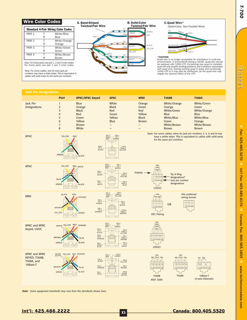
T-70
0
Int’l: 425.486.2222 Canada: 800.405.5320
Support
Fax: 42
5.4
83
.52
70
Int’l Fax: 4
25
.48
5.9
17
0
Canada Fax: 8
00
.56
3.1
85
3
ww
w.levitonvoicedata.com
Support
X3
TIP
RING
ACCESSORY
GROUND
PAIR1
PAIR 2
GREEN
BLACK
YELLOW
RED
Note: For some cables, wire for even jack pinnumbers may have a white stripe. This is equivalent to cables with solid wires for the same pin numbers.
Jack Pin 1 Blue White Orange White/Orange White/GreenDesignations 2 Orange Black Green Orange Green
3 Black Red Red White/Green White/Orange4 Red Green Yellow Blue Blue5 Green Yellow Black White/Blue White/Blue6 Yellow Blue Brown Green Orange7 Brown — — White/Brown White/Brown8 White — — Brown Brown
6P4C
6P6C
MMJ
8P8C and 8P8CKeyed, USOC
8P8C and 8P8C KEYED; T568B,T568A, and10Base-T
Jack Pin Designations
Pin# 8P8C/8P8C Keyed 6P6C MMJ T568B T568A
YELLOW RED
GREENBLACK
PIN 3RING 1RED
PIN 4TIP 1
GREEN
PIN 2TIP 2BLACK
PIN 5RING 2
YELLOW
YELLOW RED
GREEN BLACK
BLUE
WHITEPIN 3RING 1RED
PIN 4TIP 1
GREEN
PIN 2TIP 2BLACK
PIN 5RING 2
YELLOW
PIN 6RING 3
BLUE
PIN 1TIP 3WHITE
YELLOW RED
GREEN BLACK
BROWN
ORANGE
BLUE
WHITE
PIN 4RED
PIN 5GREEN
PIN 3BLACK PIN 6
YELLOW
PIN 7BROWN
PIN 1BLUE
PIN 2ORANGE
PIN 8WHITE
(SLATE)
PIN 4RING 1RED
PIN 5TIP 1
GREEN
PIN 3TIP 2BLACK
PIN 6RING 2
YELLOW
PIN 7RING 3
BROWN
PIN 1RING 4BLUE
PIN 2TIP 3ORANGE
PIN 8TIP 4
WHITE
PIN 3RING 1RED
PIN 4RING 2
YELLOW
PIN 2TIP 1
GREENPIN 5TIP 2
BLACK
PIN 6RING 3
BROWN
PIN 1TIP 3
ORANGE
1 2 3 4 5 6
+ + - + - -
T T RT R R
PR2PR3
PR1
USOC
1 2 3 4 5 6 7 8
- + + - + - - +
R T T R T R R T
PR2PR3
PR1
PR4
USOC
+ + - - + -
1 2 3 4 5 6
PR1 PR2
PR3
1 2 3 4 5 6
1 2 3 4 5 6 7 8
+ - + - + - + -
T R T R T R T R
PR2PR3PR1 PR4
1 2 3 4 5 6 7 8
+ - + - + - + -
T R T R T R T R
PR3PR2PR1 PR4
1 2 3 4 5 6 7 8
+ - + -
T R T R
PR2PR1
Note: Some equipment standards may vary from the standards shown here.
PolarityTip & Ringdesignations*Jack pin numberdesignations
OR
†No preferredwiring format
DEC Pairing
T568A 10Base-T(4-wire Ethernet)AT&T 258A
T568B
Note: For some cables, wires for jack pin numbers 2, 4, 6 and 8 mayhave a white stripe. This is equivalent to cables with solid wiresfor the same pin numbers.

Fibe
r Com
pone
nts
Fibe
r Com
pone
nts
Cab
le M
anag
emen
tCab
le M
anag
emen
tTo
ols
& A
cces
sorie
sTo
ols
& A
cces
sorie
sCop
per
Com
pone
nts
Cop
per
Com
pone
nts
Wal
lpla
tes
& H
ousi
ngs
Wal
lpla
tes
& H
ousi
ngs
Con
nect
ors
Con
nect
ors
Tech
Sup
port
Tech
Sup
port
Customer Service: 800.722.2082www.levitonvoicedata.com X4
USOC CODESUSOC CODESThis appendix contains descriptionsof Universal Service Order Codes(USOC) for connecting telephoneinstruments and related equipmentto telephone lines, based on Part 68,Subpart F, Section 68.502 of FCCregulations, and as described by theT1E1.3 Working Group on Connectorsand Wiring Arrangements.
USOC Codes were developed yearsago by the Bell operating companiesto identify service or equipmentunder tariff. Information on USOCcodes is provided here should yourun across these in your work.
A Note About USOCNumber Suffixes
RJ (Registered Jack) numbers endwith a letter that indicates the wiringor mounting method:“C” identifies a surface or flush-mounted jack.
“W” identifies a wall-mounted jack.
“X” identifies a complex multi-line orseries type jack.
T1R1T2R2
2 3 4 5 6
T1R1T2 R2
MINIATURE6-POSITIONJACKMINIATURE6-POSITIONPLUG
TO OTHEREQUIPMENT
TONETWORK
TO REGISTERED TERMINAL EQUIPMENT
T3R3
1
R3T3
2 3 4 5 61
TONETWORK
PROGRAMMINGRESISTOR
2
3 A (OR MI)4 R (P)
5 T (P)6 A1 (OR MIC)
1
RT
8 PC7 PR
T
R
MINIATURE6-POSITION
JACK
MINIATURE6-POSITION
PLUG
TO OTHEREQUIPMENT
TONETWORK
TO REGISTERED TERMINAL EQUIPMENT
2 3 4 5 61
2 3 4 5
T
R
R T
BAR SHORTREMOVEDON PLUGINSERTIONPOSITIONS1 & 4 + 5 & 8
MINIATURE8-POSITION
PLUG
TOTELCOWIRING
TONETWORK
TO REGISTERED TERMINAL EQUIPMENT
R1
T1
2 3 4 5 61 87
2 3 4 5 61 87
R1 T1
T1R1T2R2
T1R1T2R2
2 3 4 5 6
T1R1T2 R2
MINIATURE6-POSITIONJACKMINIATURE6-POSITIONPLUG
TO OTHEREQUIPMENT
TONETWORK
TO REGISTERED TERMINAL EQUIPMENT
T
R
R T
BAR SHORTREMOVEDON PLUGINSERTIONPOSITIONS1 & 4 + 5 & 8
MINIATURE8-POSITION
PLUG
TOTELCOWIRING
TONETWORK
TO REGISTERED TERMINAL EQUIPMENT
T1
R1
2 3 4 5 61 87
2 3 4 5 61 87
R1 T1
STRAP
Note: The telephone company will wire thelines in the sequence designated by thecustomer.
RJ11C/RJ11W RJ31X
RJ45SRJ125C
RJ38XRJ14C/RJ14W
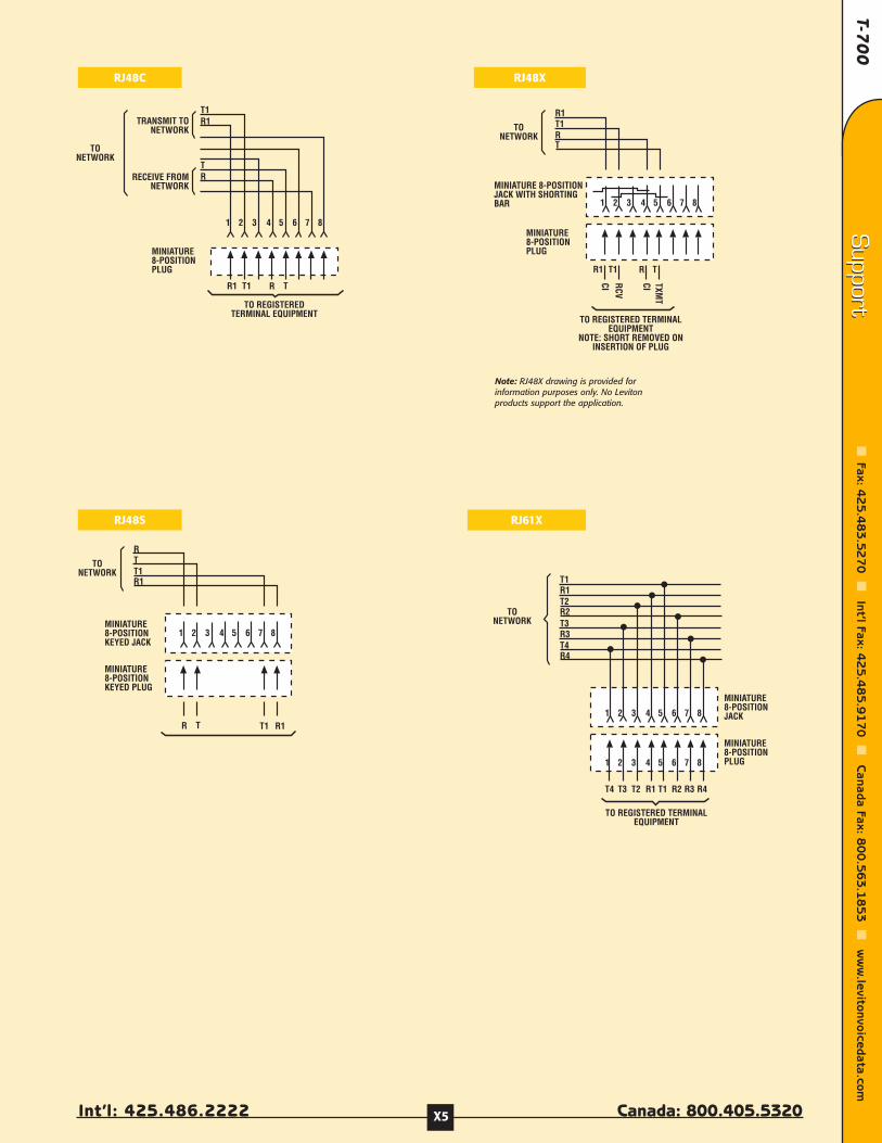
T-70
0
Int’l: 425.486.2222 Canada: 800.405.5320
Support
Fax: 42
5.4
83
.52
70
Int’l Fax: 4
25
.48
5.9
17
0
Canada Fax: 8
00
.56
3.1
85
3
ww
w.levitonvoicedata.com
Support
X5
TR
TRT1
MINIATURE8-POSITIONPLUG
TO REGISTEREDTERMINAL EQUIPMENT
R1
TRANSMIT TONETWORK
RECEIVE FROMNETWORK
TONETWORK
2 3 4 5 61 7 8
T1R1
TONETWORK
RTT1R1
TR T1
MINIATURE8-POSITIONKEYED PLUG
R1
2 3 4 5 61 7 8MINIATURE8-POSITIONKEYED JACK
TR
TONETWORK
R1T1
TRT1
MINIATURE8-POSITIONPLUG
R1
2 3 4 5 61 7 8
MINIATURE 8-POSITIONJACK WITH SHORTINGBAR
TO REGISTERED TERMINALEQUIPMENT
NOTE: SHORT REMOVED ONINSERTION OF PLUG
CI RCV
CI TXMT
TONETWORK
MINIATURE8-POSITIONJACK
T3R3T4R4
MINIATURE8-POSITIONPLUG
2 3 4 5 61 7 8
TO REGISTERED TERMINALEQUIPMENT
2 3 4 5 61 7 8
T3 T2 R1 T1 R2T4 R3 R4
T1R1T2R2
RJ48C
RJ48S
RJ48X
RJ61X
Note: RJ48X drawing is provided forinformation purposes only. No Levitonproducts support the application.
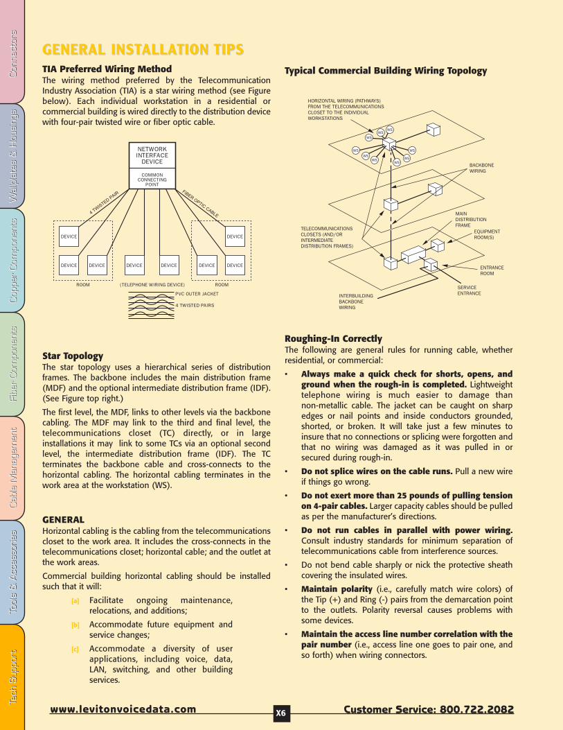
Fibe
r Com
pone
nts
Fibe
r Com
pone
nts
Cab
le M
anag
emen
tCab
le M
anag
emen
tTo
ols
& A
cces
sorie
sTo
ols
& A
cces
sorie
sCop
per
Com
pone
nts
Cop
per
Com
pone
nts
Wal
lpla
tes
& H
ousi
ngs
Wal
lpla
tes
& H
ousi
ngs
Con
nect
ors
Con
nect
ors
Tech
Sup
port
Tech
Sup
port
Customer Service: 800.722.2082www.levitonvoicedata.com X6
GENERAL INSTGENERAL INSTALLAALLATION TION TIPSTIPSTIA Preferred Wiring MethodThe wiring method preferred by the TelecommunicationIndustry Association (TIA) is a star wiring method (see Figurebelow). Each individual workstation in a residential orcommercial building is wired directly to the distribution devicewith four-pair twisted wire or fiber optic cable.
Star TopologyThe star topology uses a hierarchical series of distributionframes. The backbone includes the main distribution frame(MDF) and the optional intermediate distribution frame (IDF).(See Figure top right.)
The first level, the MDF, links to other levels via the backbonecabling. The MDF may link to the third and final level, thetelecommunications closet (TC) directly, or in largeinstallations it may link to some TCs via an optional secondlevel, the intermediate distribution frame (IDF). The TCterminates the backbone cable and cross-connects to thehorizontal cabling. The horizontal cabling terminates in thework area at the workstation (WS).
GENERALHorizontal cabling is the cabling from the telecommunicationscloset to the work area. It includes the cross-connects in thetelecommunications closet; horizontal cable; and the outlet atthe work areas.
Commercial building horizontal cabling should be installedsuch that it will:
[a] Facilitate ongoing maintenance,relocations, and additions;
[b] Accommodate future equipment andservice changes;
[c] Accommodate a diversity of userapplications, including voice, data,LAN, switching, and other buildingservices.
Roughing-In CorrectlyThe following are general rules for running cable, whetherresidential, or commercial:
• Always make a quick check for shorts, opens, andground when the rough-in is completed. Lightweighttelephone wiring is much easier to damage thannon-metallic cable. The jacket can be caught on sharpedges or nail points and inside conductors grounded,shorted, or broken. It will take just a few minutes toinsure that no connections or splicing were forgotten andthat no wiring was damaged as it was pulled in orsecured during rough-in.
• Do not splice wires on the cable runs. Pull a new wireif things go wrong.
• Do not exert more than 25 pounds of pulling tensionon 4-pair cables. Larger capacity cables should be pulledas per the manufacturer’s directions.
• Do not run cables in parallel with power wiring.Consult industry standards for minimum separation oftelecommunications cable from interference sources.
• Do not bend cable sharply or nick the protective sheathcovering the insulated wires.
• Maintain polarity (i.e., carefully match wire colors) ofthe Tip (+) and Ring (-) pairs from the demarcation pointto the outlets. Polarity reversal causes problems withsome devices.
• Maintain the access line number correlation with thepair number (i.e., access line one goes to pair one, andso forth) when wiring connectors.
EQUIPMENTROOM(S)
TELECOMMUNICATIONSCLOSETS (AND/ORINTERMEDIATEDISTRIBUTION FRAMES)
HORIZONTAL WIRING (PATHWAYS)FROM THE TELECOMMUNICATIONSCLOSET TO THE INDIVIDUALWORKSTATIONS
BACKBONEWIRING
SERVICEENTRANCE
ENTRANCEROOM
INTERBUILDINGBACKBONEWIRING
MAINDISTRIBUTIONFRAME
Typical Commercial Building Wiring Topology

T-70
0
Int’l: 425.486.2222 Canada: 800.405.5320
Support
Fax: 42
5.4
83
.52
70
Int’l Fax: 4
25
.48
5.9
17
0
Canada Fax: 8
00
.56
3.1
85
3
ww
w.levitonvoicedata.com
Support
X7
• Use the two inner pairs of a housing fortelecommunications. Use the outer pairs of theconnector for other purposes (if any) to providecompatibility with two-line telephones.
• Use plastic non-metallic staples to support wire, andleave the wire loose inside the staples—do not drivestaples all the way in. Driving staples in tightly may crimpwire and damage the insulation or wire, impairing itsability to carry voice or data.
• If conduit is installed, always leave a pull cord in tofacilitate running new wire.
• Never run power in the same conduit withtelecommunications cable. Low-voltage monitor andcontrol lines may share conduit with telecommunications.
• Avoid undercarpet runs if possible, as they areinherently more susceptible to damage, particularly inresidences. If they must be installed, follow themanufacturer’s directions carefully, and remember thatonly one transition from one type of cabling to another isstandard in a single room. Avoid installing undercarpetruns in damp areas. Note that undercarpet power cablesare not allowed in residential installations.
• Where possible, use inner walls for runs to avoidconflict with firebreaks and insulation. Inner-wallwiring also makes it a lot easier to replace wires ifnecessary, or to add wires. Nonetheless, wiring throughexternal walls is not always avoidable, so installationhandling should be the same as for electrical wire.Firestopping is also to be observed.
• Do not run telecommunications wire parallel topower wiring without adequate separation, and donot share bore holes with power wires.
• Keep wire away from sources of heat, like hot waterpipes and heater ducts.
• Avoid running external wires—they are not desirable,both for appearance and safety reasons. Wires on theoutside of a building may be allowed under local code foradditions, but should be avoided for initial installations.
• Leave 18 inches of spare wire at outlets andconnection points for connections and changes.
• Firestopping, bonding, and grounding must beperformed according to fire, building, and electricalcodes that apply.
Regardless of the installation type, proper wiring requiresgood planning and careful work to avoid damaging cablesand to make good connections.
TELECOMMUNICATIONS OUTLETS• When installing outlet boxes on wooden studs, it is
important to maintain proper separation ofcommunications and power cables. These two types ofcables should not share drill holes or stud spaces. Desktelephone connectors should be located at the samedistance from the floor as electrical outlets.
• Each workstation should, at minimum, be served byeither two 100Ω UTP cables, or one 100Ω UTP cableand one cable of another type. Single or double outletsmay be used.
• Telecommunications outlets are usually placed at thesame height as electrical outlets, and near anelectrical outlet.
GENERAL TIPS ON QUALITY INSTALLATIONS• Every connection degrades system performance, so
use the minimum necessary.
• Better to provide excess capacity in terms of cableand outlets rather than not enough. Later additionsare costly and time consuming.
• Wire to the highest anticipated data rate (speed) orgreater—never less.
• Never install components of unknown/questionableorigin or quality. At the very best, the system willtransmit signals to the level of its weakest component.Every element and connection is important.
• Document all connections carefully, and keepinstallations neat and tidy. This will save time andhassle when modifying or troubleshooting the systemlater.
• Test everything.
The Importance of Pair Twisting:The rate of twisting will range from four (4), to as many as 28 twists per foot on highspeed data cable. The tighter the twist, the less likely it will be distorted duringinstallation, and the greater the immunity from interference. While the specificationfor the rate of twist varies with the anticipated data rate carried by the installation,always untwist the least amount of cable necessary to make a connection.
* Category 3 max. allowed untwisting = 3"
* Category 5 max. allowed untwisting =< 1⁄2"
* Category 5e max. allowed untwisting =< 1⁄2"
* Category 6 max. allowed untwisting =< 1⁄2"
*Note: TIA-568-A does not specify the maximum allowable untwisting for these connectors, they are suggested as the maximum distance for standard practice.

Fibe
r Com
pone
nts
Fibe
r Com
pone
nts
Cab
le M
anag
emen
tCab
le M
anag
emen
tTo
ols
& A
cces
sorie
sTo
ols
& A
cces
sorie
sCop
per
Com
pone
nts
Cop
per
Com
pone
nts
Wal
lpla
tes
& H
ousi
ngs
Wal
lpla
tes
& H
ousi
ngs
Con
nect
ors
Con
nect
ors
Tech
Sup
port
Tech
Sup
port
Customer Service: 800.722.2082www.levitonvoicedata.com X8
EXTREME 6+ CONNECTEXTREME 6+ CONNECTOR OR TERMINATERMINATION INSTRUCTIONSTION INSTRUCTIONS
What’s the difference between T568A and T568B wiring?T568A and T568B are the two wiring standards for an8-position modular connector, permitted under theTIA-568-A wiring standards document. The onlydifference between T568A and T568B is that the orange andgreen wire pairs (pairs two and three) areinterchanged.
How to decide which wiring pattern to use:
1. Does the job specification call out a wiring pattern?
2. Does the customer/end user have a preference?
3. Have patch panels already been purchased for the job? Ifso, they will probably be either T568A or T568B. Jacksshould be wired to the same pattern as the panels.
4. Are you adding on to existing wiring? If so, your new wiringshould match existing wiring.
If none of the factors above apply, either T568A or T568B maybe used. It is important to ensure that workstation connectorsand patch panels are wired to the same pattern. T568B iscommonly used in commercial installations, while T568A isprevalent in residential installations.
T568A and T568B Wiring
5. Place the dust cap over theterminated wires forsecure connection.
eXtreme 6+ Wiring Scheme
Cable Entry from Left
➊ ➋
the connector. Maintain wirepair twisting to less than1/2˝ of the IDC contact;then, seat and trim the cableone pair at a time to preventcrushing the inside pairs.
Cable Entry from left
➊ ➋
As noted above: Route and terminate one pairat a time to avoid cable damage.
1. Remove about 3˝ of cablejacket and center spline(stiff wire separator insideCategory 6 cable).
2. Determine which wiringscheme to use, T568A orT568B. Note the associatedcolor codes and connectorpin numbers on the labellocated between the IDCconnector slots.
3. Leave the cable jacketwithin 1/8˝ of theconnector side, thenroute the wires for
termination using theselected wiring scheme.
NOTE: If terminating Category6 Connectors, route cableperpendicular to the IDCfield. Ensure there isenough slack in thetwisted pairs, and do notplace the cable jacket intothe termination field.
4. Use your fingers to carefullyseat the wires into the IDCslots. Set a 110-style impacttool to low impact andposition it perpendicular to
AB
A
B
48
48
5757
26
26
1313
CUT
Note: For some cables,wires for jack pinnumbers 2, 4, 6 and 8may have a white stripe.This is equivalent tocables with solid wires forthe same pin numbers.
Note: For some cables,wires for jack pinnumbers 2, 4, 6 and 8may have a white stripe.This is equivalent tocables with solid wires forthe same pin numbers.
Wiring Standard
Pin# T568A T568B5 White/Blue White/Blue4 Blue Blue3 White/Orange White/Green6 Orange Green1 White/Green White/Orange2 Green Orange7 White/Brown White/Brown8 Brown Brown
eXtreme 6Inside Wire
Colors
1 5 White/Blue White/Blue2 4 Blue Blue3 1 White/Orange White/Green4 2 Orange Green5 3 White/Green White/Orange6 6 Green Orange7 7 White/Brown White/Brown8 8 Brown Brown
T568A & T568B Wiring StandardsIDC Color Assignments
IDC Jack Pin T568B T568APosition Number Wire Colors Wire Colors

T-70
0
Int’l: 425.486.2222 Canada: 800.405.5320
Support
Fax: 42
5.4
83
.52
70
Int’l Fax: 4
25
.48
5.9
17
0
Canada Fax: 8
00
.56
3.1
85
3
ww
w.levitonvoicedata.com
Support
X9
GIGAMAX 5E+ COMPONENT CONNECTGIGAMAX 5E+ COMPONENT CONNECTOR OR TERMINATERMINATION TION 1. Remove about 2" of jacket
from cable.
2. Determine the wiringscheme (T568A or T568B)and note the associatedcolor codes on the labellocated on the sides of theconnector. This label alsoincludes connector pinnumbers.
5. Place the cap over theterminated wires forsecure connection andadded strain relief.
4. Using a-110 style impacttool, seat the wires into theslots of the insulationdisplacement connectors.Place the cutting side ofthe tool on the outside, totrim the excess wire flushwith the connector body asyou punch the wires down.
6. Insert connector assemblyinto platform or wallplate.Note the "UP" position ofthe connector.
B
A
Color Code ForT568A & B Wiring
Pin Number
7 8 3 6
B
A6
38
7B
A
B
A
568
568
1
Pin #45
2
1
Pin #6387
Pair 2
White/Orange
Orange
2
Pin #
White/Brown
Pin #
Brown
Pair 4
452
1
63
8
7
3
Pin # Pin #
Pair 1
21
638
7
White/Blue
Blue4
5
4
Pin # Pin #
Pair 3
452
1
8
7
6
3White/Green
Green
1
Pin #45
21
Pin #6387
Green
Pair 3
White/Green
2
Pin #
White/Brown
Pin #
Brown
Pair 4
452
1
63
8
7
3
Pin # Pin #
Pair 1
21
638
7
White/Blue
Blue4
5
4
Pin # Pin #
Pair 2
452
1
8
7
6
3White/Orange
Orange
1 White/Green White/Orange
2 Green Orange
3 White/Orange White/Green
4 Blue Blue
5 White/Blue White/Blue
6 Orange Green
7 White/Brown White/Brown
8 Brown Brown
Inside Wire Colors
Wiring StandardPin# T568A T568B
3. Route the wires fortermination, as shownbelow. Terminate one pairat a time starting from rearof connector. Terminatingeach pair after placementwill prevent crushing theinside pairs with thepunchdown tool. Lay cablein so jacket touches rear ofconnector as shown.
Note: Maintain cable jacket as close to termination as possible
T568A Gigamax 5e+ Component-Level Connector Wiring Scheme
T568B Gigamax 5e+ Component-Level Connector Wiring Scheme
Note: For some cables, wires for jack pin numbers 2, 4, 6 and 8may have a white stripe. This is equivalent to cables withsolid wires for the same pin numbers.
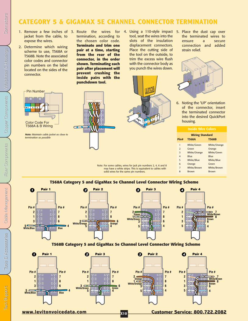
Fibe
r Com
pone
nts
Fibe
r Com
pone
nts
Cab
le M
anag
emen
tCab
le M
anag
emen
tTo
ols
& A
cces
sorie
sTo
ols
& A
cces
sorie
sCop
per
Com
pone
nts
Cop
per
Com
pone
nts
Wal
lpla
tes
& H
ousi
ngs
Wal
lpla
tes
& H
ousi
ngs
Con
nect
ors
Con
nect
ors
Tech
Sup
port
Tech
Sup
port
Customer Service: 800.722.2082www.levitonvoicedata.com X10
CCAATEGORTEGORY 5 & GIGAMAX 5E CHANNEL CONNECTY 5 & GIGAMAX 5E CHANNEL CONNECTOR OR TERMINATERMINATIONTION1. Remove a few inches of
jacket from the cable, toexpose the wires.
2. Determine which wiringscheme to use, T568A orT568B. Note the associatedcolor codes and connectorpin numbers on the labellocated on the sides of theconnector.
5. Place the dust cap overthe terminated wires toensure a secureconnection and addedstrain relief.
6. Noting the ‘UP’ orientationof the connector, insertthe terminated connectorinto the desired QuickPorthousing.
B
A4 6 8 7
Color Code ForT568A & B Wiring
Pin Number
B
A7
86
4B
A
B
A
568
568
1
Pin #213
5White/Blue
Pin #786 4Blue
Pair 1 2
Pin #21
3White/Orange
5
Pin #78
6Orange4
Pair 2 3
Pin #2
Green1
White/Green35
Pin #7864
Pair 3 4
Pin #2135
Pin #7
White/Brown8
Brown64
Pair 4
1
Pin #213
5White/Blue
Pin #786
4Blue
Pair 1 2
Pin #21
3White/Green
5
Pin #78
6Green4
Pair 3 3
Pin #2Orange
1 White/Orange
35
Pin #7864
Pair 2 4
Pin #2135
Pin #7
White/Brown8
Brown64
Pair 4
1 White/Green White/Orange
2 Green Orange
3 White/Orange White/Green
4 Blue Blue
5 White/Blue White/Blue
6 Orange Green
7 White/Brown White/Brown
8 Brown Brown
Inside Wire Colors
Wiring StandardPin# T568A T568B
3. Route the wires fortermination, according tothe chosen color code.Terminate and trim onepair at a time, startingfrom the rear of theconnector, in the ordershown. Terminating eachpair after placement willprevent crushing theinside pairs with thepunchdown tool.
Note: Maintain cable jacket as close to termination as possible
T568A Category 5 and GigaMax 5e Channel Level Connector Wiring Scheme
T568B Category 5 and GigaMax 5e Channel Level Connector Wiring Scheme
4. Using a 110-style impacttool, seat the wires into theslots of the insulationdisplacement connectors.Place the cutting side ofthe tool on the outside, totrim the excess wire flushwith the connector body asyou punch the wires down.
Note: For some cables, wires for jack pin numbers 2, 4, 6 and 8may have a white stripe. This is equivalent to cables withsolid wires for the same pin numbers.
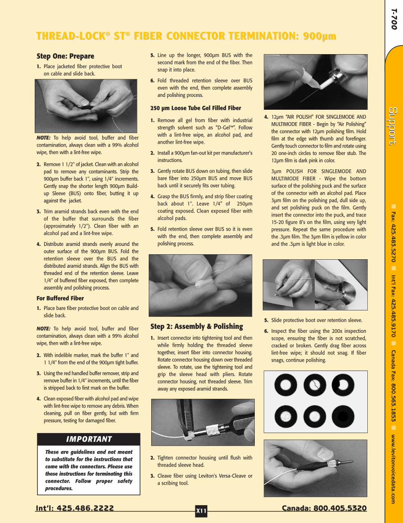
T-70
0
Int’l: 425.486.2222 Canada: 800.405.5320
Support
Fax: 42
5.4
83
.52
70
Int’l Fax: 4
25
.48
5.9
17
0
Canada Fax: 8
00
.56
3.1
85
3
ww
w.levitonvoicedata.com
Support
X11
THREAD-LOCKTHREAD-LOCK®® STST®® FIBER CONNECTFIBER CONNECTOR OR TERMINATERMINATION: 900TION: 900µµmm
Step One: Prepare1. Place jacketed fiber protective boot
on cable and slide back.
NOTE: To help avoid tool, buffer and fibercontamination, always clean with a 99% alcoholwipe, then with a lint-free wipe.
2. Remove 1 1/2" of jacket. Clean with an alcoholpad to remove any contaminants. Strip the900µm buffer back 1", using 1/4" increments.Gently snap the shorter length 900µm Build-up Sleeve (BUS) onto fiber, butting it upagainst the jacket.
3. Trim aramid strands back even with the endof the buffer that surrounds the fiber(approximately 1/2"). Clean fiber with analcohol pad and a lint-free wipe.
4. Distribute aramid strands evenly around theouter surface of the 900µm BUS. Fold theretention sleeve over the BUS and thedistributed aramid strands. Align the BUS withthreaded end of the retention sleeve. Leave1/4" of buffered fiber exposed, then completeassembly and polishing process.
For Buffered Fiber
1. Place bare fiber protective boot on cable andslide back.
NOTE: To help avoid tool, buffer and fibercontamination, always clean with a 99% alcoholwipe, then with a lint-free wipe.
2. With indelible marker, mark the buffer 1" and1 1/4" from the end of the 900µm tight buffer.
3. Using the red handled buffer remover, strip andremove buffer in 1/4" increments, until the fiberis stripped back to first mark on the buffer.
4. Clean exposed fiber with alcohol pad and wipewith lint-free wipe to remove any debris. Whencleaning, pull on fiber gently, but with firmpressure, testing for damaged fiber.
5. Line up the longer, 900µm BUS with thesecond mark from the end of the fiber. Thensnap it into place.
6. Fold threaded retention sleeve over BUSeven with the end, then complete assemblyand polishing process.
250 µm Loose Tube Gel Filled Fiber
1. Remove all gel from fiber with industrialstrength solvent such as ”D-Gel™”. Followwith a lint-free wipe, an alcohol pad, andanother lint-free wipe.
2. Install a 900µm fan-out kit per manufacturer’sinstructions.
3. Gently rotate BUS down on tubing, then slidebare fiber into 250µm BUS and move BUSback until it securely fits over tubing.
4. Grasp the BUS firmly, and strip fiber coatingback about 1". Leave 1/4” of 250µmcoating exposed. Clean exposed fiber withalcohol pads.
5. Fold retention sleeve over BUS so it is evenwith the end, then complete assembly andpolishing process.
Step 2: Assembly & Polishing1. Insert connector into tightening tool and then
while firmly holding the threaded sleevetogether, insert fiber into connector housing.Rotate connector housing down over threadedsleeve. To rotate, use the tightening tool andgrip the sleeve head with pliers. Rotateconnector housing, not threaded sleeve. Trimaway any exposed aramid strands.
2. Tighten connector housing until flush withthreaded sleeve head.
3. Cleave fiber using Leviton's Versa-Cleave ora scribing tool.
4. 12µm “AIR POLISH” FOR SINGLEMODE ANDMULTIMODE FIBER - Begin by “Air Polishing”the connector with 12µm polishing film. Holdfilm at the edge with thumb and forefinger.Gently touch connector to film and rotate using20 one-inch circles to remove fiber stub. The12µm film is dark pink in color.
3µm POLISH FOR SINGLEMODE ANDMULTIMODE FIBER - Wipe the bottomsurface of the polishing puck and the surfaceof the connector with an alcohol pad. Place3µm film on the polishing pad, dull side up,and set polishing puck on the film. Gentlyinsert the connector into the puck, and trace15-20 figure 8’s on the film, using very lightpressure. Repeat the same procedure withthe .3µm film. The 3µm film is yellow in colorand the .3µm is light blue in color.
5. Slide protective boot over retention sleeve.
6. Inspect the fiber using the 200x inspectionscope, ensuring the fiber is not scratched,cracked or broken. Gently drag fiber acrosslint-free wipe; it should not snag. If fibersnags, continue polishing.
IMPORTANTThese are guidelines and not meantto substitute for the instructions thatcome with the connectors. Please usethose instructions for terminating thisconnector. Follow proper safetyprocedures.

Fibe
r Com
pone
nts
Fibe
r Com
pone
nts
Cab
le M
anag
emen
tCab
le M
anag
emen
tTo
ols
& A
cces
sorie
sTo
ols
& A
cces
sorie
sCop
per
Com
pone
nts
Cop
per
Com
pone
nts
Wal
lpla
tes
& H
ousi
ngs
Wal
lpla
tes
& H
ousi
ngs
Con
nect
ors
Con
nect
ors
Tech
Sup
port
Tech
Sup
port
Customer Service: 800.722.2082www.levitonvoicedata.com X12
FFASTAST-CURE-CURE™™ FIBER CONNECTFIBER CONNECTOR OR TERMINATERMINATION: 900TION: 900µµmm
Step One: Prepare1. Slide the boot and the crimp tube onto the
cable, with the small end inserted first.
For 3mm Jacketed Cable: Use the ribbedboot, provided.
For 900µm Buffered Cable: Use the smoothboot, provided.
2. Strip the jacket and/or buffer usingthe measurements provided in the chartbelow. Strip in increments of 1/4”. If usingjacketed cable, trim the aramid strands asindicated, below.
3. Clean exposed fiber with a 99% isopropylalcohol pad followed by a lint-free wipe toremove any contaminants.
SC & FC Connector Types on 3mm JacketedCable ONLY:
4. Insert spacer over buffer and push all theway down, until it rests against the jacket.
Step Two: AssembleAll Connector and Fiber Types:
1. Remove the dust cap from the connector.
2. Shake the adhesive bottle before using.Remove the cap from the adhesive bottle, andattach the needle by pressing it gently onto thetop of the bottle until you feel it set into place.
NOTE: Syringes are also available for insertingadhesive.
3. Insert the needle into the back of theconnector, and squeeze the bottle gently,injecting the adhesive into the ferrule.Continue until a dot of adhesive is visible at theother end, then remove the needle. Wipe awayexcess adhesive from the end of the ferrule.
NOTE: Avoid excessively filling connectors.
4. Dip cleaned fiber into the bottle of primer. Besure to coat the entire length of exposedfiber with the primer.
5. Insert the fiber into the back of the connector,using continuous motion to prevent prematurebonding. Primer will activate adhesive andbegin the bonding process.
6. Hold the fiber in place for 10-20 seconds,and allow up to 3 minutes for the adhesiveto bond.
7. If using any cable type but jacketed fiber,slide the boot back up over the back of theconnector, now. If using jacketed fiber, followthe steps, below.
8. For SC Connectors, ensure proper orientationof body by aligning connector housing.
Additional Steps For 3mm Jacketed Cable ONLY:
9. Slide the crimp tube over the aramid strandsand connector body. Then, using a crimptool, first crimp the tube at the large end ,then the small end.
FC/ST/SC - large end: Use the .178” hex die.
FC/ST/SC - small end: Use the .151” hex die.
LC: Use the .128” hex die.
10. Slide the boot over the back of the connector.
Step Three: Cleave & PolishAll Connector and Fiber Types:
NOTE: The Thread-Lock Versa-Cleave tool is NOTrecommended for cleaving Fast-Cure Connectors.
1. When the adhesive is cured (no longer wet),scribe the fiber where it meets the bead ofadhesive at the end of the ferrule.
2. Gently pull away the fiber stub, and properlydispose of it.
NOTE: Loose fiber debris can be dangerous. Besure to properly dispose of fiber.
3. 12µm “AIR POLISH” - Begin by “Air Polishing”the connector with 12µm polishing film.Hold film at the edge with thumb andforefinger. Gently touch connector to filmand rotate using 18-20 one-inch circles toremove fiber stub. Leviton’s 12µm film isdark pink in color.
3µm & .3µm “PAD POLISH” - Wipe thebottom surface of the polishing puck and thesurface of the connector with a 99% alcoholwipe. Place 3µm film on the polishing pad,dull side up, and set polishing puck on thefilm. Gently insert the connector into thepuck, and trace 15-20 figure 8’s on the film,using very light pressure. Repeat the sameprocedure with the .3µm film. Leviton’s 3µmis yellow and the .3µm film is light blue incolor.
4. Inspect the fiber using the 200x inspectionscope, ensuring the fiber is not scratched,cracked or broken. Remove any debris usinga lint-free wipe.
5. Repeat the pad polishes if neccesary.
NOTE: When polishing LC connectors, use Leviton’s1.25mm Polishing Puck (PN# 49886-LCP).35mm
15mm10mm
40mm20mm4mm
LC W/JACKETED CABLE
20mm
IMPORTANTThese are guidelines and not meantto substitute for the instructions thatcome with the connectors. Please usethose instructions for terminating thisconnector. Follow proper safetyprocedures.
Scribe and pull fiber away.
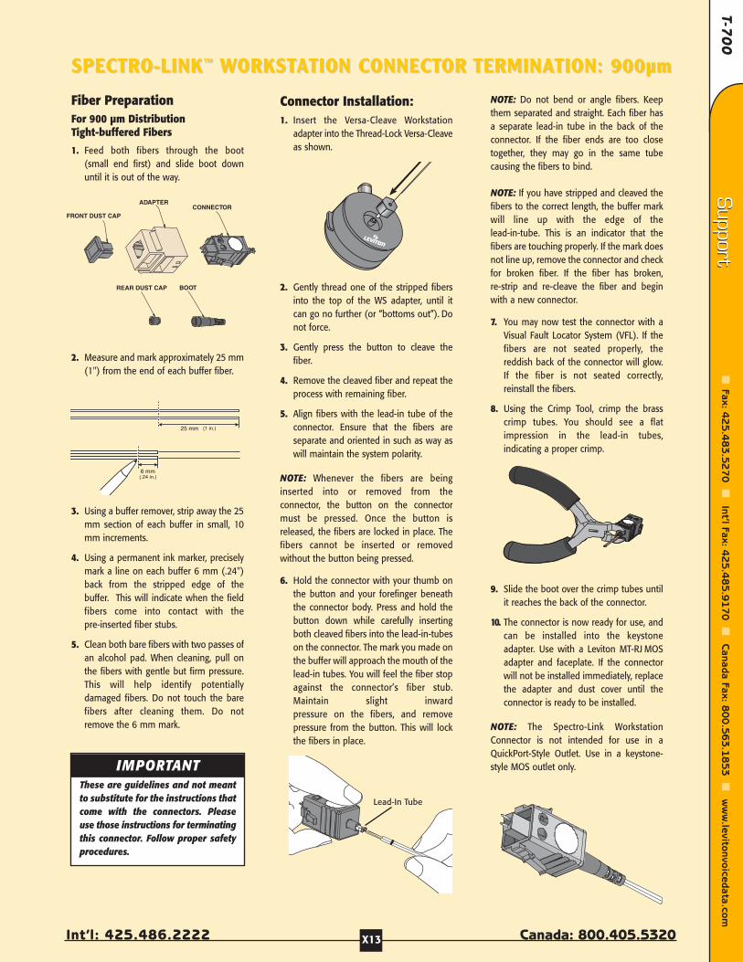
T-70
0
Int’l: 425.486.2222 Canada: 800.405.5320
Support
Fax: 42
5.4
83
.52
70
Int’l Fax: 4
25
.48
5.9
17
0
Canada Fax: 8
00
.56
3.1
85
3
ww
w.levitonvoicedata.com
Support
X13
Fiber PreparationFor 900 µm DistributionTight-buffered Fibers
1. Feed both fibers through the boot(small end first) and slide boot downuntil it is out of the way.
2. Measure and mark approximately 25 mm(1") from the end of each buffer fiber.
3. Using a buffer remover, strip away the 25mm section of each buffer in small, 10mm increments.
4. Using a permanent ink marker, preciselymark a line on each buffer 6 mm (.24")back from the stripped edge of thebuffer. This will indicate when the fieldfibers come into contact with thepre-inserted fiber stubs.
5. Clean both bare fibers with two passes ofan alcohol pad. When cleaning, pull onthe fibers with gentle but firm pressure.This will help identify potentiallydamaged fibers. Do not touch the barefibers after cleaning them. Do notremove the 6 mm mark.
Connector Installation:1. Insert the Versa-Cleave Workstation
adapter into the Thread-Lock Versa-Cleaveas shown.
2. Gently thread one of the stripped fibersinto the top of the WS adapter, until itcan go no further (or “bottoms out”). Donot force.
3. Gently press the button to cleave thefiber.
4. Remove the cleaved fiber and repeat theprocess with remaining fiber.
5. Align fibers with the lead-in tube of theconnector. Ensure that the fibers areseparate and oriented in such as way aswill maintain the system polarity.
NOTE: Whenever the fibers are beinginserted into or removed from theconnector, the button on the connectormust be pressed. Once the button isreleased, the fibers are locked in place. Thefibers cannot be inserted or removedwithout the button being pressed.
6. Hold the connector with your thumb onthe button and your forefinger beneaththe connector body. Press and hold thebutton down while carefully insertingboth cleaved fibers into the lead-in-tubeson the connector. The mark you made onthe buffer will approach the mouth of thelead-in tubes. You will feel the fiber stopagainst the connector’s fiber stub.Maintain slight inwardpressure on the fibers, and removepressure from the button. This will lockthe fibers in place.
NOTE: Do not bend or angle fibers. Keepthem separated and straight. Each fiber hasa separate lead-in tube in the back of theconnector. If the fiber ends are too closetogether, they may go in the same tubecausing the fibers to bind.
NOTE: If you have stripped and cleaved thefibers to the correct length, the buffer markwill line up with the edge of thelead-in-tube. This is an indicator that thefibers are touching properly. If the mark doesnot line up, remove the connector and checkfor broken fiber. If the fiber has broken,re-strip and re-cleave the fiber and beginwith a new connector.
7. You may now test the connector with aVisual Fault Locator System (VFL). If thefibers are not seated properly, thereddish back of the connector will glow.If the fiber is not seated correctly,reinstall the fibers.
8. Using the Crimp Tool, crimp the brasscrimp tubes. You should see a flatimpression in the lead-in tubes,indicating a proper crimp.
9. Slide the boot over the crimp tubes untilit reaches the back of the connector.
10. The connector is now ready for use, andcan be installed into the keystoneadapter. Use with a Leviton MT-RJ MOSadapter and faceplate. If the connectorwill not be installed immediately, replacethe adapter and dust cover until theconnector is ready to be installed.
NOTE: The Spectro-Link WorkstationConnector is not intended for use in aQuickPort-Style Outlet. Use in a keystone-style MOS outlet only.
SPECTRO-LINKSPECTRO-LINK™™ WWORKSTORKSTAATION CONNECTTION CONNECTOR OR TERMINATERMINATION: 900TION: 900µµmm
FRONT DUST CAP
ADAPTERCONNECTOR
REAR DUST CAP BOOT
25 mm (1 in.)
6 mm(.24 in.)
Lead-In Tube
IMPORTANTThese are guidelines and not meantto substitute for the instructions thatcome with the connectors. Pleaseuse those instructions for terminatingthis connector. Follow proper safetyprocedures.

Fibe
r Com
pone
nts
Fibe
r Com
pone
nts
Cab
le M
anag
emen
tCab
le M
anag
emen
tTo
ols
& A
cces
sorie
sTo
ols
& A
cces
sorie
sCop
per
Com
pone
nts
Cop
per
Com
pone
nts
Wal
lpla
tes
& H
ousi
ngs
Wal
lpla
tes
& H
ousi
ngs
Con
nect
ors
Con
nect
ors
Tech
Sup
port
Tech
Sup
port
Customer Service: 800.722.2082www.levitonvoicedata.com X14
SPECTRO-LINKSPECTRO-LINK™™ FRAME-STFRAME-STAATION CONNECTTION CONNECTOR OR TERMINATERMINATION: 900TION: 900µµmm
Connector Preparation
NOTE: This procedure REQUIRES the LevitonFrame-Station Connector Assembly Tool thatcomes in the Spectro-Link MT-RJ Tool Kit(see Page D9).
1. Flip the crimp handle of theFrame-Station Connector Assembly Toolopen and rotate so that the wrenchhandle is in the “UP” position.
2. Remove and discard the cap from therear of the connector.
3. Examine the connector to make sure it isin the open position. The connector is inthe open position when the key on thecam is positioned 90º from the “UP”lettering on top of the dust cap.
4. Pull back the slider of the ConnectorAssembly Tool and insert the connector,oriented as shown, into the tool as far asit will go. The lead-in tube should rest onthe crimp platform when theconnector is fully seated. Do not force.
Connector
Lead-in tube
Front dust cap
U P
Wrench handleCrimp platform
Slider
Crimp handle
RL
Fiber PreparationFor 900 µm DistributionTight-buffered Fibers
1. Feed both fibers through the boot (smallend first) and slide boot down until it isout of the way.
2. Measure and mark approximately 25 mm(1") from the end of each buffer fiber.
3. Using a buffer remover, strip away the25 mm section of each buffer in small,10 mm increments.
4. Using a permanent ink marker,precisely mark a line on each buffer 13mm (.51") back from the stripped edgeof the buffer.
5. Clean both bare fibers with two passes ofan alcohol pad. When cleaning, pull onthe fibers with gentle but firm pressure.This will help identify potentiallydamaged fibers. Do not touch the barefibers after cleaning them.
Connector Installation:1. Insert the Versa-Cleave Frame-Station
adapter into the Thread-LockVersa-Cleave as shown.
2. Gently thread one of the stripped fibersinto the top of the FS adapter, until it cango no further. Do not force.
3. Gently press the button to cleave.
4. Remove the cleaved fiber and repeat theprocess with remaining fiber.
5. Align fibers with the lead-in tube of theconnector. Ensure that the fibers areseparate and oriented in such a way aswill maintain the system polarity.
6. Carefully insert both cleaved fibers intothe lead-in tube until you feel themfirmly stop against the connector’spre-inserted fiber stub. Be sure to guide
fibers evenly, without bending or angling.If you feel resistance at the entry funnel,pull the fibers back out a short distanceand re-insert.
NOTE: The buffer mark will line up with theedge of the lead-in-tube. This is an indicatorthat the fibers are touching properly.
7. Rotate the wrench handle of theConnector Assembly Tool to the “DOWN”position, to cam the connector. Thewrench must stay down––do not rotateit back upright.
8. The fiber is now held inside theconnector by the cam.
9. You may now test the connector with aVisual Fault Locator System (VFL).
WARNING: Use a Leviton Frame-StationConnector Assembly Tool to crimp the fiber.
10.Flip the crimp handle back. You shouldsee a flat impression in the crimp tube,indicating a proper crimp. Leave thewrench handle down. Remove theconnector by lifting it and its fibersstraight up and out of the tool. Do notpull the fibers or cable away from thecrimped tube. Handle the connector only.
11.Slide the boot back up onto theconnector until it reaches the cam.
12.The connector is now ready to use.
NOTE: The Spectro-Link Frame-StationConnector can be used at the workstationwith the addition of a Spectro-LinkQuickPort Adapter or Spectro-Link KeystoneAdapter.
n-relief boots
Boot
U P
Lead-in tube
Slider Wrench handle
U P
RL
25 mm (1 in.)
13 mm(.51 in.)
>90°
U P
RL
U P
Crimp handle
IMPORTANTThese are guidelines and not meantto substitute for the instructions thatcome with the connectors. Pleaseuse those instructions for terminatingthis connector. Follow proper safetyprocedures.
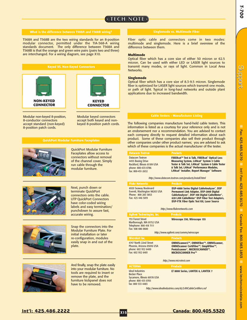
T-70
0
Int’l: 425.486.2222 Canada: 800.405.5320
Support
Fax: 42
5.4
83
.52
70
Int’l Fax: 4
25
.48
5.9
17
0
Canada Fax: 8
00
.56
3.1
85
3
ww
w.levitonvoicedata.com
Support
X15
Keyed VS. Non-Keyed Connectors
Modular non-keyed 8-position,8-conductor connectorsaccept standard (non-keyed)8-position patch cords.
Modular keyed connectorsaccept both keyed and non-keyed 8-position patch cords.
NON-KEYEDCONNECTOR
KEYEDCONNECTOR
What is the difference between T568A and T568B wiring?
T568A and T568B are the two wiring standards for an 8-positionmodular connector, permitted under the TIA-568-A wiringstandards document. The only difference between T568A andT568B is that the orange and green wire pairs (pairs two and three)are interchanged. For a wiring diagram, see page X10.
Singlemode vs. Multimode Fiber
QuickPort Modular Furniture Faceplates
QuickPort Modular FurnitureFaceplates allow access toconnectors without removalof the channel cover. Simplyrun cable through themodular furniture.
Next, punch down orterminate QuickPortconnectors onto the cable.UTP QuickPort Connectorshave color-coded wiringlabels and easy termination/punchdown to assure fast,accurate wiring.
Snap the connectors into theModular Furniture Plate. Forinitial installation or laterre-configuration, moduleseasily snap in and out of theplate.
And finally, snap the plate easilyinto your modular furniture. Notools are required to insert orremove the plate, and thefurniture kickpanel does nothave to be removed.
Fiber optic cable and connectors come in two modes: multimode and singlemode. Here is a brief overview of thedifference between them.
MultimodeOptical fiber which has a core size of either 50 micron or 62.5micron. Can be used with either LED or LASER light sources totransmit many modes, or rays of light. Common in Local AreaNetworks.
SinglemodeOptical fiber which has a core size of 8.3-9.5 micron. Singlemodefiber is optimized for LASER light sources which transmit one mode,or path of light. Typical in long-haul networks and outside plantapplications due to increased bandwidth.
The following companies manufacture hand-held cable testers. Thisinformation is listed as a courtesy for your reference only and is notan endorsement nor a recommendation. You are advised to contacteach company directly to request detailed information about eachproduct. Some of these companies also sell their product throughother companies under other product names; you are advised to askwhich of these companies is the actual manufacturer of the tester.
Datacom Textron Products
6920 Seaway BoulevardEverett, Washington 98203 USAPhone: 800 283 5853Fax: 425 446 5019
http://www.flukenetworks.com
DSP-4000 Series Digital CableAnalyzer™, DSPPermanent Link Adapter, DSP-2000 DigitalCableAnalyzer™, DSP-100 Digital CableMeter®,620 LAN CableMeter®, DSP Fiber Test Adapters,DSP-FTK Fiber Optic Test Kit, Laser Source
Fluke Networks Products
Datacom Textron4455 Boeing DriveRockford, Illinois 61109 USAphone: 800-435-0786fax: 800-451-2632
http://www.datacom.textron.com/products/install.html
FIBERcat™ Test & Talk, FIBERcat™ Optical LossMeasuring System, LANcat® System 5 CableTester & Talk Set, LANcat® System 6 Cable Tester& Talk Set, LANcat® Performance Modules,LANcat® Installer, Report Manager™ Software
4747 North 22nd StreetPhoenix, Arizona 85016 USAphone: 602 952 6400Fax: 602 952 6401
http://www.microtest.com
OMNIScanner2™, OMNIFiber™, OMNIScanner,OMNIScanner CertiFiber™, SimpliFiber™,PentaScanner®, MICROSCANNER™,MICROSCANNER Pro™
Microtest Inc. Products
753 Forest StreetMarlborough, MA 01752 USATelephone: 800 418 7111Fax: 508 486 0600
http://www.agilent.com/comms/wirescope
Wirescope 350, Wirescope 155
Agilent Technologies, Inc. Products
Ideal IndustriesBecker PlaceSycamore, Illinois 60178 USAphone: 800 435 0705fax: 800 533 4483
http://www.idealindustries.com/dc/LANCableCertifiers.nsf
LT 8000 Series, LANTEK 6, LANTEK 7
ACTERNA Products
Cable Testers - Manufacturer Listing
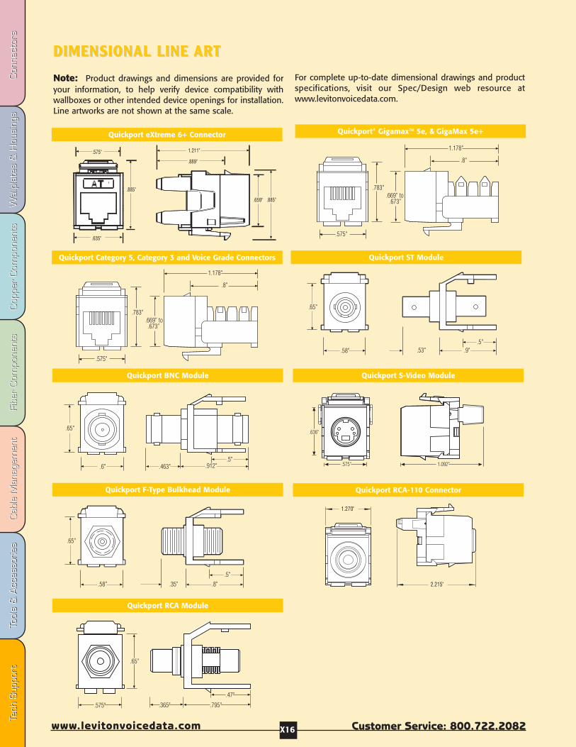
Fibe
r Com
pone
nts
Fibe
r Com
pone
nts
Cab
le M
anag
emen
tCab
le M
anag
emen
tTo
ols
& A
cces
sorie
sTo
ols
& A
cces
sorie
sCop
per
Com
pone
nts
Cop
per
Com
pone
nts
Wal
lpla
tes
& H
ousi
ngs
Wal
lpla
tes
& H
ousi
ngs
Con
nect
ors
Con
nect
ors
Tech
Sup
port
Tech
Sup
port
Customer Service: 800.722.2082www.levitonvoicedata.com X16
DIMENSIONAL LINE DIMENSIONAL LINE ARTART
Note: Product drawings and dimensions are provided foryour information, to help verify device compatibility withwallboxes or other intended device openings for installation.Line artworks are not shown at the same scale.
For complete up-to-date dimensional drawings and productspecifications, visit our Spec/Design web resource atwww.levitonvoicedata.com.
Quickport® Gigamax™ 5e, & GigaMax 5e+Quickport eXtreme 6+ Connector
Quickport F-Type Bulkhead Module
Quickport Category 5, Category 3 and Voice Grade Connectors
Quickport BNC Module
Quickport ST Module
Quickport RCA Module
Quickport RCA-110 Connector
.575" .365" .795"
.47"
.65"
Quickport S-Video Module
1.092".575"
.636"
.35" .8".5"
.65"
.58"
.65"
.6" .463" .912".5"
.783"
.575"
.8"
1.178"
.669” to.673”
.65"
.58" .53" .9".5"
.783"
.575"
.8"
1.178"
.669” to.673”
2.215"
1.270"
.575"
.635"
.885"
.889"
1.211"
.659" .885"
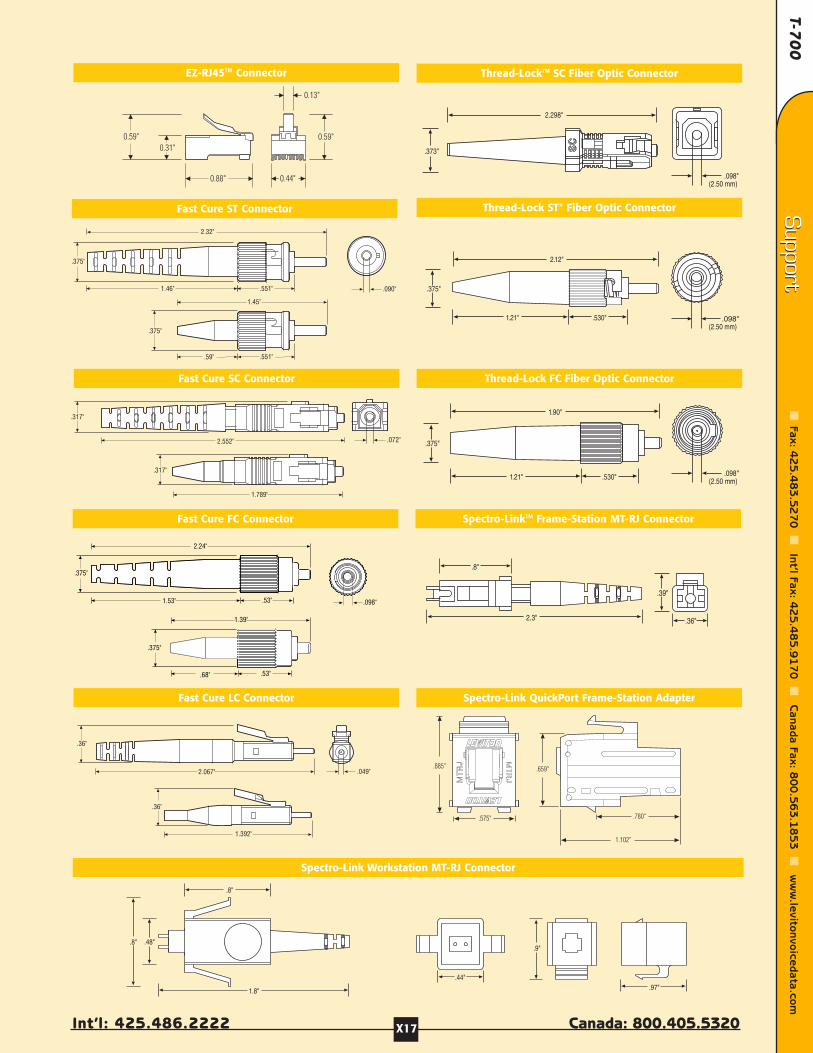
T-70
0
Int’l: 425.486.2222 Canada: 800.405.5320
Support
Fax: 42
5.4
83
.52
70
Int’l Fax: 4
25
.48
5.9
17
0
Canada Fax: 8
00
.56
3.1
85
3
ww
w.levitonvoicedata.com
Support
X17
EZ-RJ45TM Connector
Thread-Lock ST® Fiber Optic ConnectorFast Cure ST Connector
Thread-LockTM SC Fiber Optic Connector
Spectro-Link Workstation MT-RJ Connector
2.12"
.375"
1.21" .530" .098"(2.50 mm)
.098"(2.50 mm)
1.90"
1.21" .530"
.375"
2.298"
.373"
.098"(2.50 mm)
.8"
1.8"
.8" .48"
2.3"
.8"
Spectro-LinkTM Frame-Station MT-RJ Connector
.44".97"
.9"
.39"
.36"
Thread-Lock FC Fiber Optic Connector
Spectro-Link QuickPort Frame-Station Adapter
Fast Cure FC Connector
Fast Cure SC Connector
Fast Cure LC Connector
.659"
.780"
1.102"
.575"
.885"
.53"1.53"
2.24"
.375"
.098"
.072"
.317"
2.552"
.090".551"1.46"
2.32"
.375"
1.45"
.59" .551"
.375"
0.59"
0.44"
0.13"
0.59"
0.88"
0.31"
.53".68"
1.39"
.375"
2.067"
.36"
.049"
1.392"
.36"
.317"
1.789"
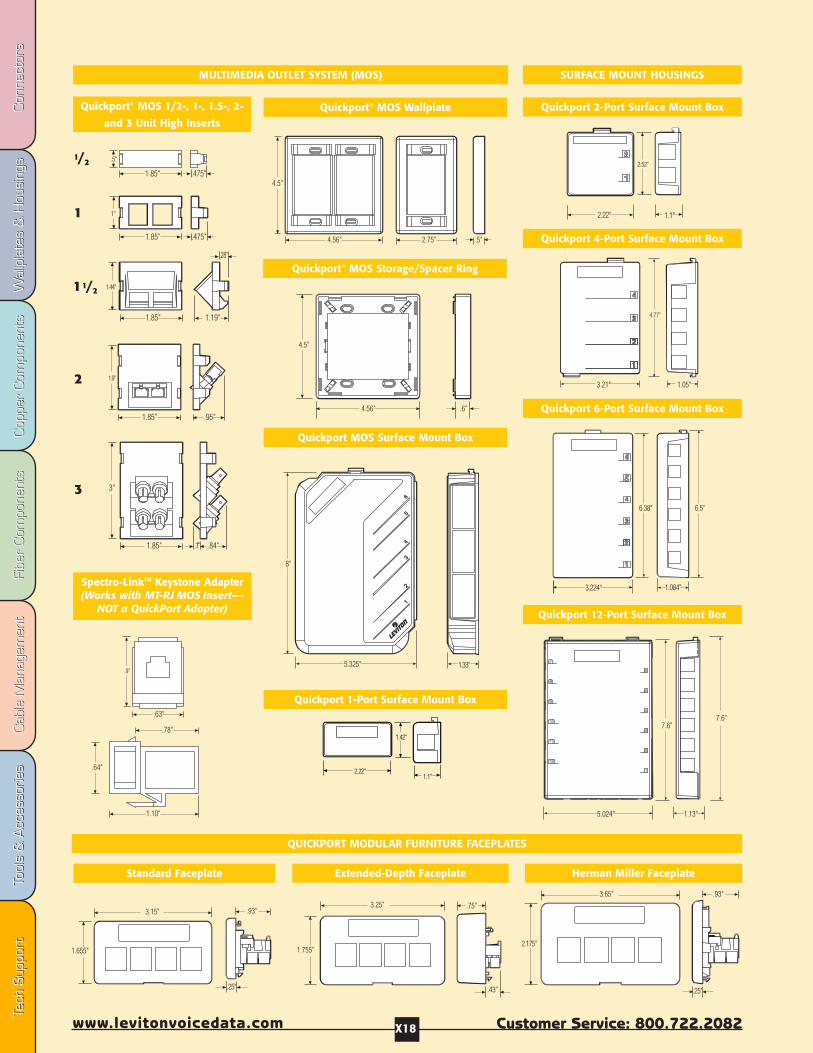
Fibe
r Com
pone
nts
Fibe
r Com
pone
nts
Cab
le M
anag
emen
tCab
le M
anag
emen
tTo
ols
& A
cces
sorie
sTo
ols
& A
cces
sorie
sCop
per
Com
pone
nts
Cop
per
Com
pone
nts
Wal
lpla
tes
& H
ousi
ngs
Wal
lpla
tes
& H
ousi
ngs
Con
nect
ors
Con
nect
ors
Tech
Sup
port
Tech
Sup
port
Customer Service: 800.722.2082www.levitonvoicedata.com X18
5.024"
7.6"
1.13"
7.6"
MULTIMEDIA OUTLET SYSTEM (MOS)
Quickport® MOS Wallplate Quickport 2-Port Surface Mount Box
Quickport® MOS Storage/Spacer Ring
Quickport MOS Surface Mount Box
Quickport 1-Port Surface Mount Box
Quickport 4-Port Surface Mount Box
Quickport 6-Port Surface Mount Box
Quickport 12-Port Surface Mount Box
Quickport® MOS 1/2-, 1-, 1.5-, 2-
and 3 Unit High Inserts
SURFACE MOUNT HOUSINGS
Spectro-LinkTM Keystone Adapter(Works with MT-RJ MOS Insert––
NOT a QuickPort Adapter)
2.175"
.25"
.93"3.65"
2.18
.43"
.75"3.25"
1.755"
.93"
.25"
1.655"
3.15"
QUICKPORT MODULAR FURNITURE FACEPLATES
Herman Miller FaceplateExtended-Depth FaceplateStandard Faceplate
1/2
1
11/2
2
3
1.1"
1.42"
2.22"
1.1"
2.52"
2.22"
3.21" 1.05"
4.77"
3.224" 1.084"
6.38" 6.5"
5.325"
8"
1.33"
4.56"
4.5"
.6"
4.5"
4.56" 2.75" .5"
1.9"
1.85” .95"
3"
1.85" .84".1"
1"
1.85" .475"
1.85"
1.44"
.28"
1.19"
.5"
1.85" .475"
1.10"
.78"
.64"
.63"
.9"
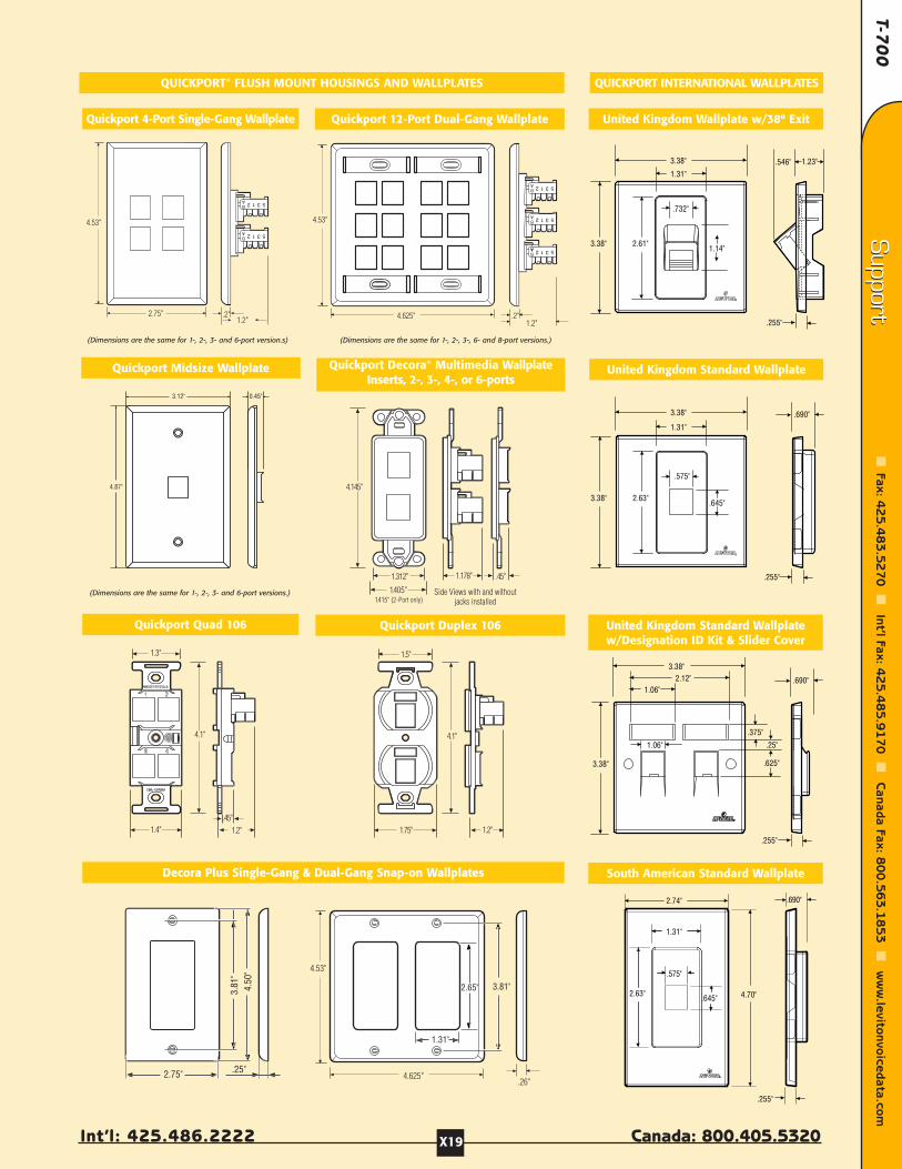
T-70
0
Int’l: 425.486.2222 Canada: 800.405.5320
Support
Fax: 42
5.4
83
.52
70
Int’l Fax: 4
25
.48
5.9
17
0
Canada Fax: 8
00
.56
3.1
85
3
ww
w.levitonvoicedata.com
Support
X19
1.3"
1.4".45"
4.1"
1.2"
4.145"
1.312" 1.178" .45"
1.405"1.415" (2-Port only)
Side Views with and withoutjacks installed
.2"1.2"
4.625"
4.53"
1.2"
4.53"
2.75" .2"
QUICKPORT® FLUSH MOUNT HOUSINGS AND WALLPLATES QUICKPORT INTERNATIONAL WALLPLATES
Quickport 4-Port Single-Gang Wallplate Quickport 12-Port Dual-Gang Wallplate United Kingdom Wallplate w/38º Exit
Quickport Midsize Wallplate United Kingdom Standard WallplateQuickport Decora® Multimedia WallplateInserts, 2-, 3-, 4-, or 6-ports
Decora Plus Single-Gang & Dual-Gang Snap-on Wallplates South American Standard Wallplate
United Kingdom Standard Wallplatew/Designation ID Kit & Slider Cover
(Dimensions are the same for 1-, 2-, 3- and 6-port version.s)
(Dimensions are the same for 1-, 2-, 3- and 6-port versions.)
(Dimensions are the same for 1-, 2-, 3-, 6- and 8-port versions.)
4.50
"
2.75" .25"
3.81
"
4.87"
3.12" 0.45"
Quickport Quad 106
1.5"
1.75"
4.1"
1.2"
Quickport Duplex 106
.255"
1.31"
2.63"
3.38"
.575"
.645"3.38"
.690"
.255"
1.06"2.12"
1.06"
3.38"
3.38"
.375"
.25"
.625"
.690"
.255"
1.31"
2.61"
3.38"
.732"
1.14"3.38"
1.23".546"
2.74" .690"
1.31"
2.63" 4.70"
.255"
.575"
.645"3.81"
.26"
4.53"
4.625"
1.31"
2.65"

Fibe
r Com
pone
nts
Fibe
r Com
pone
nts
Cab
le M
anag
emen
tCab
le M
anag
emen
tTo
ols
& A
cces
sorie
sTo
ols
& A
cces
sorie
sCop
per
Com
pone
nts
Cop
per
Com
pone
nts
Wal
lpla
tes
& H
ousi
ngs
Wal
lpla
tes
& H
ousi
ngs
Con
nect
ors
Con
nect
ors
Tech
Sup
port
Tech
Sup
port
Customer Service: 800.722.2082www.levitonvoicedata.com X20
1.31"
1.31"
1.75"
19"
3.5"
Front View
10"
2.3"
Side View
1.9"
STANDARD AND UNIVERSAL PRE-CONFIGURED PATCH PANELS
Category 5 and GigaMax 5e Patch Blocks
Category 5, GigaMax™ 5e, and Voice Grade 24- and 48-Port Panels
eXtreme 6+ 24- and 48-Port Universal Patch Panels
Side view for preconnectorizedvoice grade panel
Side view for 110 voice
grade panel1.24"
1.24"
1.33"
1.33"
4.845"3.97
19"
3.475"1 2 3 4 5 6 7 8 9 10 11 12
25 26 27 28 29 30 31 32 33 34 35 36
13 14 15 16 17 18 19 20 21 22 23 24
37 38 39 40 41 42 43 44 45 46 47 48
3.475"
19"
4.855"
Universal GigaMax 5e 48-Port Angled Patch Panel
eXtreme 6+ 48-Port Angled Patch Panel
1.483"
3.475"
19"
1.479"
1.725"
19"
eXtremeTM 6+ Patch Block
10.00"
2.300" 2.300"
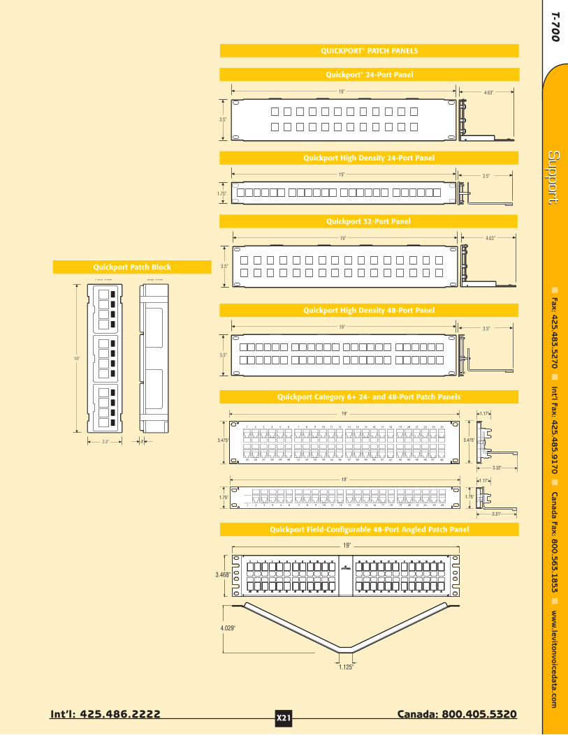
T-70
0
Int’l: 425.486.2222 Canada: 800.405.5320
Support
Fax: 42
5.4
83
.52
70
Int’l Fax: 4
25
.48
5.9
17
0
Canada Fax: 8
00
.56
3.1
85
3
ww
w.levitonvoicedata.com
Support
X21
3.5"
19" 3.5"
3.5"
19" 4.63"
1.75"
19" 3.5"
3.5"
19" 4.63"
Front View Side View
10"
2.3" .4"
Quickport Patch Block
Quickport® 24-Port Panel
Quickport High Density 24-Port Panel
Quickport High Density 48-Port Panel
Quickport Category 6+ 24- and 48-Port Patch Panels
QUICKPORT® PATCH PANELS
Quickport 32-Port Panel
Quickport Field-Configurable 48-Port Angled Patch Panel
19"
3.475" 3.475"
1 2 3 4 5 6 7 8 9 10 11 12 13 14 15 16 17 18 19 20 21 22 23 24
25 26 27 28 29 30 31 32 33 34 35 36 37 38 39 40 41 42 43 44 45 46 47 48
1.17"
3.32"
19"
1.75" 1.75"
1.17"
1 2 3 4 5 6 7 8 9 10 11 12 13 14 15 16 17 18 19 20 21 22 23 24
3.31"
3.468"
19"
1.125"
4.029"
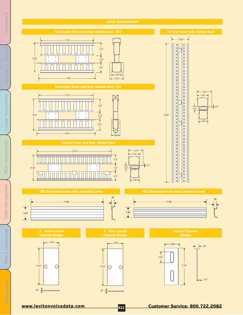
Fibe
r Com
pone
nts
Fibe
r Com
pone
nts
Cab
le M
anag
emen
tCab
le M
anag
emen
tTo
ols
& A
cces
sorie
sTo
ols
& A
cces
sorie
sCop
per
Com
pone
nts
Cop
per
Com
pone
nts
Wal
lpla
tes
& H
ousi
ngs
Wal
lpla
tes
& H
ousi
ngs
Con
nect
ors
Con
nect
ors
Tech
Sup
port
Tech
Sup
port
Customer Service: 800.722.2082www.levitonvoicedata.com X22
Horizontal Front and Rear Slotted Duct, 2RU Vertical Front Only Slotted Duct
Horizontal Front and Rear Slotted Duct, 1RU
Vertical Front and Rear Slotted Duct
2RU Horizontal Front Only Extended Cover 1RU Horizontal Front Only Extended Cover
5" Front LateralChannel Divider
4" Rear LateralChannel Divider
Vertical ChannelDivider
CABLE MANAGEMENT
2.35"
10.00"
17.50"
4.25"
2.50"
3.25"
19.00"
3.386"
3.475"
4.25"
3.25"
19.00"
10.00"
17.50"
1.886"
1.886"
1.886"
2.50"
5.38"
4.25"
35.00"
1.50"
4.25"
1.50"10.00"
4.38"
6.63"
.075"
83.00"
10.00"
5.38"
1.50"
4.38"
6.63"
.075"
11.50"
3.90"
.03"
11.50"
4.90"
.03"
11.50"
.50"
2.50"
3.929"
.110"
17.50"
3.25"
.55"
17.50".55"
1.90"
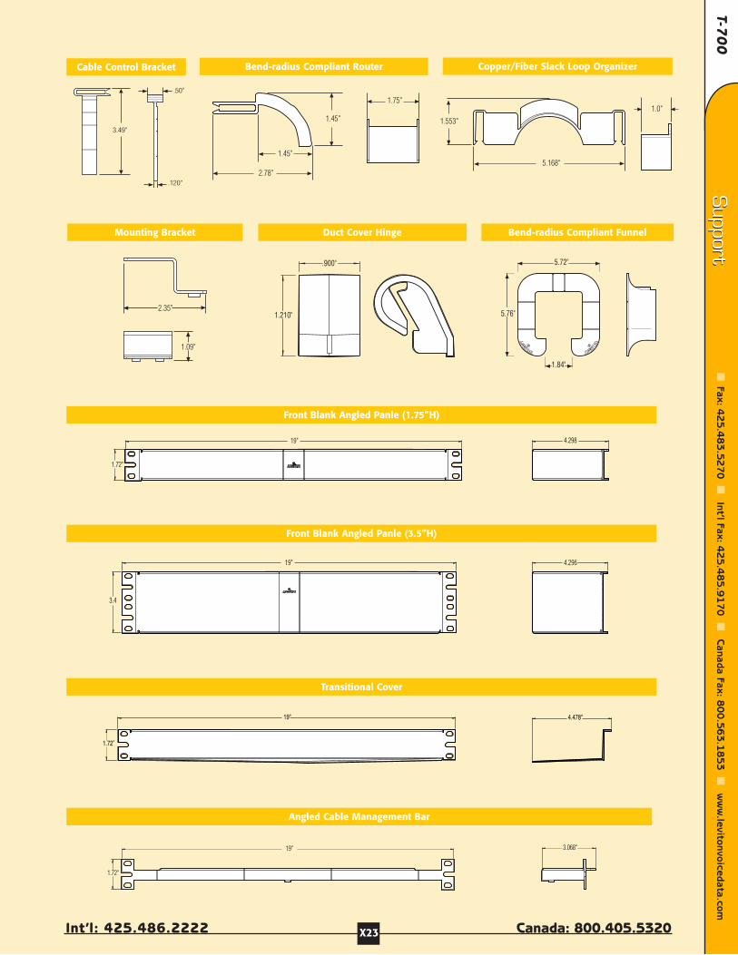
T-70
0
Int’l: 425.486.2222 Canada: 800.405.5320
Support
Fax: 42
5.4
83
.52
70
Int’l Fax: 4
25
.48
5.9
17
0
Canada Fax: 8
00
.56
3.1
85
3
ww
w.levitonvoicedata.com
Support
X23
Bend-radius Compliant RouterCable Control Bracket
Front Blank Angled Panle (1.75”H)
Front Blank Angled Panle (3.5”H)
Transitional Cover
Angled Cable Management Bar
1.210"
.900"
1.84"
5.76"
5.72"
3.49"
.50"
.120"2.78"
1.45"
1.45"
1.75"
Copper/Fiber Slack Loop Organizer
1.553"
5.168"
1.0"
Mounting Bracket Duct Cover Hinge Bend-radius Compliant Funnel
2.35"
1.09"
19"
1.72"
3.068"
4.298
1.72"
19"
3.4
19" 4.296
1.72"
19" 4.478"
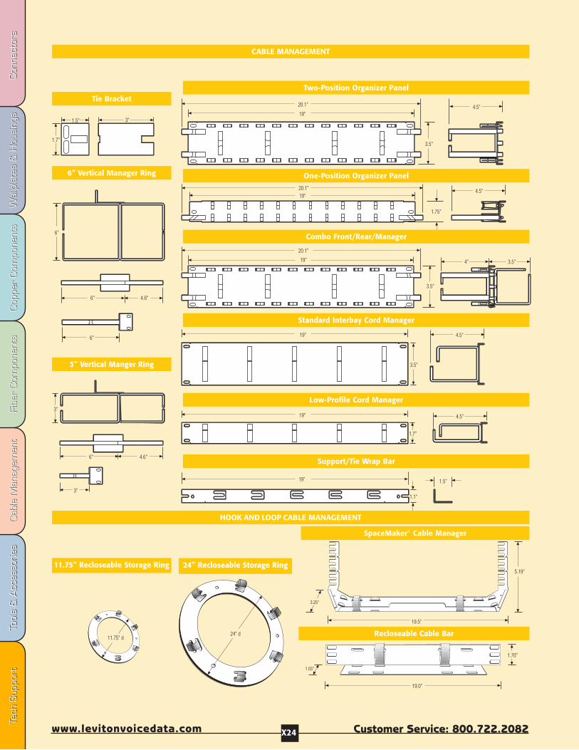
Fibe
r Com
pone
nts
Fibe
r Com
pone
nts
Cab
le M
anag
emen
tCab
le M
anag
emen
tTo
ols
& A
cces
sorie
sTo
ols
& A
cces
sorie
sCop
per
Com
pone
nts
Cop
per
Com
pone
nts
Wal
lpla
tes
& H
ousi
ngs
Wal
lpla
tes
& H
ousi
ngs
Con
nect
ors
Con
nect
ors
Tech
Sup
port
Tech
Sup
port
Customer Service: 800.722.2082www.levitonvoicedata.com X24
1.7"
3"1.5"
3"
6" 4.6"
3"
6"
6"
6"
4.6"
20.1"
19"
3.5"
4.5"
1.75"
20.1"19"
4.5"
3.5"4"
20.1"
19"
3.5"
19"
3.5"
4.5"
19"
1.7"
4.5"
19" 1.5"
1.1"
24" d11.75" d
1.70"
19.0"
19.5"
5.19"
1.03"
3.25"
CABLE MANAGEMENT
Two-Position Organizer PanelTie Bracket
One-Position Organizer Panel
Combo Front/Rear/Manager
Standard Interbay Cord Manager
Low-Profile Cord Manager
6” Vertical Manager Ring
3” Vertical Manger Ring
Support/Tie Wrap Bar
HOOK AND LOOP CABLE MANAGEMENT
11.75” Recloseable Storage Ring
SpaceMaker® Cable Manager
Recloseable Cable Bar
24” Recloseable Storage Ring

T-70
0
Int’l: 425.486.2222 Canada: 800.405.5320
Support
Fax: 42
5.4
83
.52
70
Int’l Fax: 4
25
.48
5.9
17
0
Canada Fax: 8
00
.56
3.1
85
3
ww
w.levitonvoicedata.com
Support
X25
3.61"
3"
2.81".5"1.57"
2.88"
Top View End View
2.81".5"1.57"
2.88"
1.8"1.2"
Top View End View
10"
Top View Side View
5.3"
2.2"
8.11"
2.09"1.91" 1.66" 1.53" 1.59"
8.5"
Top View End View
5.56"
3.44"
1.41"
3.38"
Top View End View
10.7"
8.11"
3.62"
3.46"
3.3"
8.46"
Top View End View
5.3"
1.73"
2.52"
10.72 "
.5"8.46"
1.8" 1.73"
2.52"
4.37"
Top View End View
Top View End View
10.7"
8.11"
10.87"
10.63"
3.3"
10.7"
Top View End View
8.11"
1.8"1.66"
3.3"
8.5"
Top View End View
5.3"
1.66"
1.41"
1.62"
110 PRODUCTS
110 50-Pair Wiring Base
110 100-Pair Wiring Base
110 50-Pair Wiring Base with legs
100-Pair Legs
50-Pair Legs
110 89D 50-Pair Wiring Base
110 100-Pair Wiring Base with Legs
110 300-Pair Wiring Base with Legs
110 Horizontal Cord Manager with Legs
110 Horizontal Cord Manager without Legs

Fibe
r Com
pone
nts
Fibe
r Com
pone
nts
Cab
le M
anag
emen
tCab
le M
anag
emen
tTo
ols
& A
cces
sorie
sTo
ols
& A
cces
sorie
sCop
per
Com
pone
nts
Cop
per
Com
pone
nts
Wal
lpla
tes
& H
ousi
ngs
Wal
lpla
tes
& H
ousi
ngs
Con
nect
ors
Con
nect
ors
Tech
Sup
port
Tech
Sup
port
Customer Service: 800.722.2082www.levitonvoicedata.com X26
19"
Top View End View
5.23"
1.75" 19"
Top View End View
3.46"
1.75"
19"
Top View End View
1.73"
2.87" 19"
Top View End View
1.73"
1.75"
8.5"
Front View Side View
5"
21.5"
9.13"
3.5"
19.13"
5.63"
4.09"2.63"
.926"
1.50".24"
.3"
8.5"
Front View Side View
5"
3.5"
16.38"
.926"
1.197".24"
.3"
.926"
.90".24"
.3"16.79"
8.25"
8.5"
1"8.38"
9"
Front View Side View
5.5"
1.5"
1.5"
16.44"
6"
3.5"
8.25"
21.5"
11"
8.5"1"8.38"
9.25"
Front View Side View
5.63"
2.63"4.09"
1.5"
1.5"
19.13"
6"
110 PRODUCTS
110 Vertical Cord Manager with Tray
110 Tower
110 Rack Mount Horizontal Cord Manager
110 Rack Mount 300-Pair Wiring Base
110 Rack Mount 100-Pair Wiring Base
110 Rack Mount 200-Pair Wiring Base
110 Vertical Cord Manager Extension
110 Tower Extension 110 C-5 Connector Block
110 C-4 Connector Block
110 C-3 Connector Block

T-70
0
Int’l: 425.486.2222 Canada: 800.405.5320
Support
Fax: 42
5.4
83
.52
70
Int’l Fax: 4
25
.48
5.9
17
0
Canada Fax: 8
00
.56
3.1
85
3
ww
w.levitonvoicedata.com
Support
X27
19"
12"
5.25"
3.5"
13"
8"
12"
14"
5.25"
17"
15"
5.25"
FIBER PRODUCTS
Small Wall-Mount Panel Medium Wall-Mount Panel Large Wall-Mount Panel
6RU Rack-Mount Panel
Two Six Pack Plate Bulkhead
Mounting Plate
Fiber Density Chart
WALL MOUNT DENSITY
SmallHolds up to 2 Mounting Plates
6-pack ST = up to 12 Fibers8-pack ST = up to 16 Fibers6-pack FC = up to 12 Fibers8-pack FC = up to 16 Fibers3-pack Duplex SC = up to 12 Fibers6-pack SC = up to 24 Fibers6-pack MT-RJ/LC = up to 24 Fibers12-pack MT-RJ/LC = up to 48 Fibers
MediumHolds up to 4 Mounting Plates
6-pack ST = up to 24 Fibers8-pack ST = up to 32 Fibers6-pack FC = up to 24 Fibers8-pack FC = up to 32 Fibers3-pack Duplex SC = up to 24 Fibers6-pack SC = up to 48 Fibers6-pack MT-RJ/LC = up to 48 Fibers12-pack MT-RJ/LC = up to 96 Fibers
LargeHolds up to 12 Mounting Plates
6-pack ST = up to 72 Fibers8-pack ST = up to 96 Fibers6-pack FC = up to 72 Fibers8-pack FC = up to 96 Fibers3-pack Duplex SC = up to 72 Fibers6-pack SC = up to 144 Fibers6-pack MT-RJ/LC = up to 144 Fibers12-pack MT-RJ/LC = up to 288 Fibers
Low-Profile 1RU Rack-Mount Panel
12"
1.75"
19"19"
3.5"
12"
Universal 2RU Panel 3RU Rack-Mount Panel
19"
12"
10.44"
17"
RACK MOUNT DENSITY
Low Profile 1RUHolds 1 Bulkhead w/or w/o 2 Mounting Plates
6-pack ST = up to 12 Fibers 8-pack ST = up to 16 Fibers6-pack FC = up to 12 Fibers 8-pack FC = up to 16 Fibers3-pack Duplex SC = up to 12 Fibers6-pack SC = up to 24 Fibers6-pack MT-RJ/LC = up to 24 Fibers12-pack MT-RJ/LC = up to 48 Fibers
2RUHolds up to 6 Mounting Plates
6-pack ST = up to 36 Fibers8-pack ST = up to 48 Fibers6-pack FC = up to 36 Fibers8-pack FC = up to 48 Fibers3-pack Duplex SC = up to 36 Fibers6-pack SC = up to 72 Fibers6-pack MT-RJ/LC = up to 72 Fibers12-pack MT-RJ/LC = up to 144 Fibers
3RUHolds up to 12 Mounting Plates
6-pack ST = up to 72 Fibers8-pack ST = up to 96 Fibers6-pack FC = up to 72 Fibers8-pack FC = up to 96 Fibers3-pack Duplex SC = up to 72 Fibers6-pack SC = up to 144 Fibers6-pack MT-RJ/LC = up to 144 Fibers12-pack MT-RJ/LC = up to 288 Fibers
6RUHolds up to 24 Mounting Plates
6-pack ST = up to 144 Fibers8-pack ST = up to 192 Fibers6-pack FC = up to 144 Fibers8-pack FC = up to 192 Fibers3-pack Duplex SC = up to 144 Fibers6-pack SC = up to 288 Fibers6-pack MT-RJ/LC = up to 288 Fibers12-pack MT-RJ/LC = up to 576 Fibers
16.882"
1.56".56"
1.25"
4.937"

Fibe
r Com
pone
nts
Fibe
r Com
pone
nts
Cab
le M
anag
emen
tCab
le M
anag
emen
tTo
ols
& A
cces
sorie
sTo
ols
& A
cces
sorie
sCop
per
Com
pone
nts
Cop
per
Com
pone
nts
Wal
lpla
tes
& H
ousi
ngs
Wal
lpla
tes
& H
ousi
ngs
Con
nect
ors
Con
nect
ors
Tech
Sup
port
Tech
Sup
port
Customer Service: 800.722.2082www.levitonvoicedata.com X28
American National StandardsInstitute (ANSI)Sales DepartmentAmerican National Standards Institute11 West 42nd Street, 13th FloorNew York, NY 10036(212) 642-4980(212) 302-1286 (FAX)www.ansi.org
American Society of TestMeasurement (ASTM)1916 Race StreetPhiladelphia, PA 19103-1187(215) 299-5585(215) 977-9679 (FAX)
Telcordia TechnologiesBellcore Customer Service8 Corporate PlacePiscataway, NJ 08854-4196(800) 521-CORE (2673)(732) 336-2559 (FAX)www.telcordia.com
BICSIBuilding Industry Consulting Service International 8610 Hidden River ParkwayTampa, FL 33637-1000(800) 242-7405(813) 971-4311 (FAX)www.bicsi.org
Canadian Standards AssociationStandards Sales5060 Spectrum Way Ste. 100Mississauga, OntarioCanada L4W 5N6(416) 747-4044(416) 747-2570 (FAX)www.csa.ca
Department of Communications(Canada)See Canadian Standards Association
Exchange Carriers Standards Association5430 Grosvenor LaneBethesda, MD 20814
Federal CommunicationsCommission445 12th Street SWWashington, DC 20554(888) 225-5322(202) 418-0232 (FAX)www.fcc.gov
Global Engineering Documents15 Inverness Way EastEnglewood, CO 80112(800) 854-7179(303) 397-2740 (FAX)www.global.ihs.com
Institute of Electrical andElectronic Engineers, Inc.IEEE Customer Service Center445 Hoes LanePO Box 1331Piscataway, NJ 08854-1331(800) 678-4333(732) 981-9667 (FAX)www.ieee.org
Insulated Cable EngineersAssociation, Inc.PO Box 440 South Yarmouth, MA 02664(508) 394-4424(508) 394-1194 (FAX)www.icea.net
International Organization forStandardization/InternationalElectrotechnical CommissionSee Global Engineering or PhillipsBusiness Info.
InternationalTelecommunications Union/International Telegraph andTelephone ConsultativeCommitteeSee Global Engineering or PhillipsBusiness Info.
National Fire Protection AgencyCustomer Sales & Service:(800) 344-3555(617) 770-0700 (FAX)Batterymarch ParkPO Box 9101Quincy, MA 02269www.nfpa.org
Phillips Business Info. 1201 Seven Locks Road, Ste. 300Potomac, MD 20854(301) 424-3338(800) 777-5006(301) 309-3847 (FAX)www.phillips.com
Telecommunications Industry Association2500 Wilson Blvd, Suite 300Arlington, VA 22201(703) 907-7700(703) 907-7727www.tiaonline.org
Underwriters Laboratories, Inc.Corporate Progress333 Pfingsten RoadNorthbrook, IL 60062-2096(847) 272-8800(847) 272-8129 (FAX)www.ul.com
STSTANDANDARDS DOCUMENT INFORMAARDS DOCUMENT INFORMATION SOURCESTION SOURCES

T-70
0
Int’l: 425.486.2222 Canada: 800.405.5320
Support
Fax: 42
5.4
83
.52
70
Int’l Fax: 4
25
.48
5.9
17
0
Canada Fax: 8
00
.56
3.1
85
3
ww
w.levitonvoicedata.com
Support
X29
Most of these definitions havebeen extracted (with editing forspace restrictions) from Newton’sTelecom Dictionary (15th Edition),published by Telecom Library, Inc.To purchase a copy, write to:Telecom Library, 12 West 21 Street,New York, NY 10010 or visit yourfavorite online bookstore.
AATM Asynchronous Transfer Mode. A very high-speedtransmission technology, ATM features high bandwidth, lowdelay, packet-like switching and multiplexing. Utilizes fixed-size cells with header and information fields.
Amplitude The distance between high or low points of awaveform or signal. Also referred to as wave “height”.
Attenuation Loss of volume during transmission, ordecrease in the power of a signal, light beam, or light wave.Measured in decibels. Opposite of gain.
AWG American Wire Gauge. Standard measuring gauge fornon-ferrous conductors (i.e., non-iron and non-steel). Gaugemeasures the diameter of a conductor (thickness of cable).
BBackbone Wiring The physical/electrical interconnectionsbetween telecommunications closets and equipment rooms.Cross-connect hardware and cabling in the Main andIntermediate Cross-Connects are considered part of thebackbone wiring.
Bandwidth The difference between the highest and thelowest frequencies of a transmission channel (path forinformation transmission). Identifies the amount of data thatcan be sent through a given channel. Measured in Hertz (Hz);higher bandwidth numbers mean higher data capacity.
Bend Radius (Fiber) Radius of curvature that a fiber canbend without breaking. Also see Cable Bend Radius.
BICSI (Building Industry Consulting Service International)BICSI is a non-profit professional association, for thepromotion of telecom industry standards.
Bit Error Rate (BER) In digital applications, the percentageof bits received in error to the total number of bits received.Usually expressed as a number to the power of 10. Forexample 10 to the fifth power means that one in every100,000 bits transmitted will be wrong.
Buffer Coating Protective material coating applied to fibers.Stated in microns.
Bus A network topology in which nodes are connected to asingle cable with terminations at each end.
CCable Assembly A fixed length of cable with connectorsinstalled on both ends. Sometimes called a Patch Cord, orPatch Cable.
Cable Bend Radius The amount of bend that can occurbefore a cable may sustain damage or increased attenuation.
Category 3 CAT3, A Category of Performance for inside wireand cable systems. Commonly used for voice applicationsand data to 10Mbps. Defined by FCC Part 68, ANSI/EIA/TIA-568, TIA TSB-36 and TIA TSB-40.
Category 5 CAT5, A Category of Performance for inside wireand cable systems. Used in support of voice and dataapplications requiring a carrier frequency of up to 100 MHz.Now the most common cabling being installed for LANconnectivity. Defined by FCC Part 68, EIA/TIA-568, TIA TSB-36and TIA TSB-40.
Category 5e (Enhanced) CAT5e, A Category of Performancefor inside wire and cable. Used in support of signalling ratesof up to 100MHz over distances of up to 100 meters. Calls fortighter twists, electrical balancing between pairs and fewercable anomalies. CAT5e is intended to support 100Base-T,ATM and Gigabit Ethernet.
Category 6 CAT6, A developing cable standard forUnshielded Twisted Pair (UTP) intended to support signalingrates up to 200 MHz. Applications will include 100Base-T, ATMand Gigabit Ethernet and wiring under development.
Category of Performance Cabling and cabling componentstandard adopted by the telecommunications industry.
Cladding The transparent material, usually glass, thatsurrounds the core of an optical fiber, causing any dispersedlight to be reflected back into the central core, therebyhelping to maintain signal strength over long distances.
Cleaving To cut the end of fiber at 90 degrees with as fewrough edges as possible before a fiber termination.
CO Central Office. Telephone company facility wheresubscribers’ lines are joined to switching equipment forconnection to each other, locally and long distance.Sometimes the same as the overseas term “public exchange”.
Coaxial Cable A cable composed of an insulated centralconducting wire wrapped in another cylindrical conductor(the shield). The whole thing is usually wrapped in anotherinsulating layer and an outer protective layer. A coaxial cablehas great capacity to carry vast quantities of information. It istypically used in high-speed data and CATV applications.
Compliance A wiring device that meets all characteristics ofa standard is said to be in compliance with that standard.
Conductor Any substance, usually a wire or cable, that cancarry an electrical current.
Connecting Block Also called a terminal block, punch-downblock, quick-connect block, or crossconnect block. A plasticblock containing metal wiring terminals to establishconnections from one group of wires to another. Usually eachwire can be connected to several other wires in a bus orcommon arrangement. There are several types of connectingblocks: 66 clip, BIX, Krone, 110, etc. A connecting block hasinsulation displacement connections (IDCs), which meansyou don’t have to remove insulation from around the wireconductor before you “punch it down” (terminate it).
GLOSSARGLOSSARYY
Fibe
r Com
pone
nts
Fibe
r Com
pone
nts
Cab
le M
anag
emen
tCab
le M
anag
emen
tTo
ols
& A
cces
sorie
sTo
ols
& A
cces
sorie
sCop
per
Com
pone
nts
Cop
per
Com
pone
nts
Wal
lpla
tes
& H
ousi
ngs
Wal
lpla
tes
& H
ousi
ngs
Con
nect
ors
Con
nect
ors
Tech
Sup
port
Tech
Sup
port
Customer Service: 800.722.2082www.levitonvoicedata.com X30
Connector A device that connects wires or fibers in cable toequipment or other wires or fibers. Wire and opticalconnectors most often join transmission media to equipmentor cross connects. A connector at the end of a telephone cableor wire is used to join that cable to another cable with amating connector or to some other telecommunicationsdevice. Note: Connectors are sometimes referred to as jacks,but though all jacks are connectors, not all connectors arejacks.
Crossconnect Distribution system equipment used toterminate and administer communication circuits. In a wirecrossconnect, jumper wires or patch cords are used to makecircuit connections. In an optical crossconnect, fiber patchcords are used. The crossconnect is located in an equipmentroom, riser closet, or satellite closet.
Crosstalk See Near-End Crosstalk.
DDaisy Chain In telecommunications, a wiring method whereeach telephone jack in a building is wired in series from theprevious jack. Daisy chain is NOT the preferred wiring method,since a break in the wiring would disable all jacks"downstream" from the break. See also Home Run.
dB (Decibel) A dB is a unit of measure of signal strength,usually the relation between a transmitted signal and astandard signal source. Every 3dB equals 50% of signalstrength, so therefore a 6dB loss is a loss of 75% of totalsignal strength.
Demarcation Point The point of interconnection betweentelephone company terminal equipment and your buildingwiring. The protective apparatus or wiring at a subscriber’spremises.
Device As distinguished from equipment. In telecom-munications, a “device” is the physical interconnection outlet.Equipment (a computer, phone, fax machine, etc.) then plugsinto the device. See also Equipment and Plug.
Drop Wire Outside wire pair(s) from the telco plant (cable),to a house or building for connection to a protector.
DTMF Acronym for Dual Tone, Multi-Frequency. See Tone Dial.
EEIA Electronic Industries Alliance. A trade organization ofmanufacturers which set standards for use of its membercompanies. Many associations fall under the umbrella of EIA,though it has recently been absorbed by the TIA, orTelecommunications Industry Association. See www.eia.org orwww.tiaonline.org.
Electromagnetic Interference (EMI) The interference insignal transmission or reception caused by the radiation ofelectrical and magnetic fields.
Equipment As distinguished from Device. Telecomequipment (computers, phones, faxes, etc.) plugs intotelecommunications outlets or devices. See also Device.
Epoxy Connector A type of fiber optic connector thatrequires a chemical bond, or epoxy.
Ethernet A type of local area network used for connectingcomputers, printers, workstations, terminals, etc. within thesame building. Ethernet is a physical link and data linkprotocol that operates over twisted pair wire and over coaxialcable at speeds up to 10Mbps. Ethernet LANs are beingpromoted by DEC, Intel and Xerox. Compare with Token Ring.
FFerrule A component of a fiber optic connection that holdsa fiber in place and aids in its alignment.
Fiber Optics A technology in which light is used to transportinformation from one point to another. More specifically, fiberoptics are thin filaments of glass through which light beamsare transmitted over long distances carrying enormousamounts of data.
HHeadroom (also called Overhead or Margin) The numberof decibels by which a system exceeds the minimum definedrequirements. The benefit of headroom is that it reduces thebit error rate (BER), and provides a performance 'safety net' tohelp ensure that current and future high speed applicationswill run at peak accuracy, efficiency and throughput.
Home Run Telephone system wiring where the individualcables run from each telephone directly back to the centralswitching equipment. Home run cabling can be thought of as“star” cabling. Every cable radiates out from the centralequipment. All PBXs and virtually all key systems work onhome run cabling. Some local area networks work on homerun wiring. See also Star Wiring, Daisy Chain.
Hub The point on a network where circuits are connected.Also, a switching node. In local area networks, a hub is thecore of a star as in ARCNET, StarLAN, Ethernet, and TokenRing. Hub hardware can be either active or passive. Wiringhubs are useful for their centralized management capabilitiesand for their ability to isolate nodes from disruption.
Hybrid Connector A connector containing both optical fiberand electrical conductors.
IInsertion Loss The difference in the amount of powerreceived before and after something is inserted into thecircuit. In optical fiber, insertion loss is the optical power lossdue to all causes, usually expressed as decibel/kilometer.
Insulation Displacement Connection (IDC) A type of wiretermination where wire is “punched down” into a metal holderwhich cuts into the insulation wire and makes contact withthe conductor, causing the electrical connection to be made.
IDF Intermediate Distribution Frame. A metal rack designedto connect cables and located in an equipment room or closet.Consists of components that provide the connection betweeninter-building cabling and the intra-building cabling, i.e.between the Main Distribution Frame (MDF) and individualtelephone wiring. There’s usually a permanent, large cablerunning between the MDF and IDF. The changes in wiring aredone at the IDF. This saves confusion in wiring.
T-70
0
Int’l: 425.486.2222 Canada: 800.405.5320
Support
Fax: 42
5.4
83
.52
70
Int’l Fax: 4
25
.48
5.9
17
0
Canada Fax: 8
00
.56
3.1
85
3
ww
w.levitonvoicedata.com
Support
X31
IEEE 802.3 IEEE stands for the Institute of Electrical andElectronic Engineers, a publishing and standards-making bodyresponsible for many standards used in LANs, including the802 series. Ethernet and StarLan both follow the 802.3standard. Typically they transmit at 10 megabits per second.This is the most common local area network specification.
Impedance The total opposition (i.e. resistance andreactance) a circuit offers to the flow of alternating current. Itis measured in ohms, and the lower the ohmic value, thebetter the quality of the conductor.
Interconnect 1. A circuit administration point, other than acrossconnect or an information outlet, that provides capabilityfor routing and rerouting circuits. It does not use patch cordsor jumper wires, and typically is a jack-and-plug device usedin smaller distribution arrangements or that connects circuitsin large cables to those in smaller cables. 2. An InterconnectCompany is one which sells, installs, and maintains telephonesystems for end users, typically businesses.
ISDN Integrated Services Digital Network. According to AT&T,today’s public switched phone network has many limitations;ISDN’s vision is to overcome these deficiencies.
JJack A receptacle used in conjunction with a plug to makeelectrical contact between communication circuits. Jacks andtheir associated plugs are used in a variety for connectinghardware applications including cross connects, interconnects,information outlets, and equipment connections. Jacks areused to connect cords or lines to telephone systems. A jack isthe female component of a plug/jack connector system, andmay be standard, modified, or keyed.
Jacket Also Cable Jacket or Sheath. The outer coveringapplied over internal cable elements for protection.
LLAN Local Area Network. A short distance network (typicallywithin a building or campus) used to link together computersand peripheral devices (such as printers) under some form ofstandard control.
Loop 1. Typically a complete electrical circuit. 2. The loop isalso the pair of wires that winds its way from the central officeto the telephone set or system at the customer’s office, homeor factory (i.e., 'premises' in telephony terms).
MMbps Megabits Per Second. One million bits per second.(Different from MBps, or a million bytes per second.)
MDF Main Distribution Frame. A wiring arrangement whichconnects the telephone lines coming from outside on oneside and the internal lines on the other. A main distributionframe may also carry protective devices as well as function asa central testing point.
MHz Megahertz. A unit of frequency denoting one millionHertz (i.e., 1,000,000 cycles per second).
Micron One thousandth of a millimeter, or one millionth ofa meter. Can be used to specify the core diameter of fiber-optic network cable.
MMJ Modified Modular Jack. A six-wire modular jack withthe locking tab shifted off to the right side. Used in the DECwiring system.
Modular Equipment is said to be modular when it is madeof “plug-in units” which can be added together to make thesystem larger, improve the capabilities, or expand its size.
MT-RJ A small form factor fiber optic connector that isdefined by its high density footprint and RJ47 lockingmechanism.
Multimode An optical fiber designed to allow light to carrymultiple carrier signals, distinguished by frequency or phase,at the same time. (Contrasts with singlemode.)
NNanometer One billionth of a meter, abbreviated nm. Thenanometer is a convenient unit for describing the wavelengthof light.
Near-End Crosstalk (NEXT) Electrical noise coupled fromone pair of wires to another within a multi-pair cable.
Network A network ties things together. Computer networksconnect all types of computers and computer- related things—terminals, printers, modems, door entry sensors, temperaturemonitors, etc. The networks we’re most familiar with are longdistance ones, like telephones and trains. Local AreaNetworks (LANs) connect computer equipment within abuilding or campus.
OOpen (Fault) Means that the circuit is not complete or thecable/fiber is broken.
Outlet A telecommunications outlet is a single-piece cabletermination assembly (typically on the floor or in the wall),containing one or more modular telecom jacks. Such jacksmight be RJs, coaxial terminators, fiber optic couplers, etc. Seealso Device and Equipment.
PPart 68 Requirements Specifications established by the FCCas the minimum acceptable protection communicationsequipment must provide the telephone network.
Patching A means of connecting circuits via cords andconnectors that can be easily disconnected and reconnectedat another point. May be accomplished by using modularcords connected between jack fields or by patch cordassemblies that plug onto connecting blocks.
PBX Private Branch Exchange. A small, privately-ownedversion of the phone company’s larger telephone centralswitching office.
Performance Compare with Compliance. A device canexhibit performance characteristics without being compliantto an industry standard.
Plug A male component of a plug/jack connector system. Inpremises wiring, a plug provides the means for a user toconnect communications equipment to the communicationsoutlet.
Fibe
r Com
pone
nts
Fibe
r Com
pone
nts
Cab
le M
anag
emen
tCab
le M
anag
emen
tTo
ols
& A
cces
sorie
sTo
ols
& A
cces
sorie
sCop
per
Com
pone
nts
Cop
per
Com
pone
nts
Wal
lpla
tes
& H
ousi
ngs
Wal
lpla
tes
& H
ousi
ngs
Con
nect
ors
Con
nect
ors
Tech
Sup
port
Tech
Sup
port
Customer Service: 800.722.2082www.levitonvoicedata.com X32
Polarity Which side of an electrical circuit is the positive?Which is the negative? Polarity is the term describing which iswhich.
POTS Plain Old Telephone Service. The basic service supplyingstandard single line telephones, telephone lines and access tothe public switched network. Just receive and place calls. Noadded features like Call Waiting or Call Forwarding.
Power Sum A test method for four pair cable whereby themathematical sum of pair-to-pair crosstalk from three pairs toone pair is measured.
Premises Telephony term for the space occupied by acustomer or authorized/joint user in a building(s) oncontinuous or contiguous property (except railroad rights ofway, etc.) not separated by a public road or highway.
Premises Wiring System The entire wiring system on theuser’s premises, especially the supporting wiring thatconnects the communications outlets to the network interfacejack.
RRBOC Regional Bell Operating Company. Seven RBOCs exist,each of which owns two or more Bell Operating Companies(BOCs). The RBOCs were carved out of the old AT&T/BellSystem during the divestiture of the Bell operating companiesfrom AT&T in 1984.
RCDD The RCDD (Registered Communications DistributionDesigner) title is a professional rating granted by BICSI (theBuilding Industry Consulting Service International). RCDDshave demonstrated a superior level of knowledge of thetelecommunications wiring industry and associateddisciplines.
Return Loss A measure of the similarity of the impedance ofa transmission line and the impedance at its terminations. Itis a ratio, expressed in decibels, of the power of the outgoingsignal to the power of the signal reflected back.
Ring As in Tip and Ring. One of the two wires needed to setup a telephone connection. See Tip.
RJ Registered Jack. RJs are telephone and datajacks/applications registered with the FCC. Numbers, like RJ-11, RJ-45, etc. are widely misused in the telecommunicationsindustry. A much more precise way to identify a jack is tospecify the number of positions (width of opening) andnumber of conductors. Example: "8-position, 8-conductorjack" or "6-position, 4-conductor jack".
SSeries Wiring See Daisy Chain.
Service Loop When a device is terminated to the wire in thecommunications outlet, a fair amount of “slack” should be lefton the wire and wound in the box to accommodate futuretrimming when devices are changed out.
Singlemode A fiber that allows only a single mode of light topropagate. This eliminates the main limitation to bandwidth,modal dispersion.
Splice The joining of two or more cables together byconnecting the conductors pair-to-pair.
Standards Agreed principles of protocol. Standards are setby committees working under various trade and internationalorganizations.
Star Wiring/Star Topology See Home Run.
TT1 A standard for digital transmission in North America. Adigital transmission link with a capacity of 1.544 Mbps(1,544,000 bits per second.) T1 lines are used for connectingnetworks across remote distances. Bridges and routers areused to connect LANs over T1 networks.
Talk Battery The DC voltage supplied by the central office tothe subscriber’s loop, which allows voice conversation.
TCP/IP A set of protocols developed by the department ofthe defense to link dissimilar computers across many kinds ofnetworks.
Telco An Americanism for TELephone COmpany.
Ten Base-T See 10Base-T at end of Glossary.
Terminate To connect a wire conductor to something,typically a piece of equipment.
TIA Telecommunications Industry Association. A tradeorganization of manufacturers which sets standards for use ofits member companies. Formerly fell under the umbrella ofEIA, (Electronic Industries Alliance). See www.tiaonline.org.
Tip 1. The first wire in a pair of wires. (The second wire iscalled the “Ring” wire.) 2. A conductor in a telephone cablepair which is usually connected to positive side of a battery atthe telco. It is the telephone industry’s equivalent of Groundin a normal electrical circuit. See Ring.
Tone Dial A push-button telephone dial that makes adifferent sound (in fact, a combination of two tones) for eachnumber pushed. The technically correct name for tone dial isDual Tone Multi Frequency, or DTMF.
Token Ring A ring topology for a local area network (LAN) inwhich a supervisory frame, or token, must be received by anattached terminal or workstation before that terminal orworkstation can start transmitting. The workstation with thetoken then transmits and uses the entire bandwidth ofwhatever communications media the token ring network isusing.
A token ring can be wired as a circle or a star, with theworkstations wired to a central wiring center, or to multiplewiring centers. The most common wiring scheme is called astar-wired ring. Whatever the wiring, a token ring LAN alwaysworks logically as a circle, with the token passing around thecircle from one workstation to another.
The advantage of token ring LANs is that media faults (brokencable) can be fixed easily, since it’s easy to isolate the faults.Token rings are typically installed in centralized closets, withloops snaking to served workstations.

T-70
0
Int’l: 425.486.2222 Canada: 800.405.5320
Support
Fax: 42
5.4
83
.52
70
Int’l Fax: 4
25
.48
5.9
17
0
Canada Fax: 8
00
.56
3.1
85
3
ww
w.levitonvoicedata.com
Support
X33
Topology As in network topology. The geometric physical orelectrical configuration describing a local communicationnetwork; the shape or arrangement of a system. The mostcommon topologies are the bus, ring and star.
TP-PMD Twisted Pair - Physical Media Dependent.Technology under review by the ANSI X3T9.5 working groupthat allows 100Mbps transmission over twisted-pair cable.
Twisted Pair Two insulated copper wires twisted aroundeach other to reduce induction (thus interference) from onewire to the other. The twists, or lays, are varied in length toreduce the potential for signal interference between pairs.Several sets of twisted pair wires may be enclosed in a singlecable. In cables greater than 25 pairs, the twisted pairs aregrouped and bound together.
UUL Underwriters Laboratories, a privately owned companythat tests to make sure that products meet safety standards.UL also administers a program for the certification ofCategory-Rated Cable.
USOC Universal Service Order Code. An old Bell system termidentifying a particular service or equipment offered undertariff.
UTP Unshielded Twisted Pair. See Twisted Pair.
WWorkstation The working area in a building required by onetelecommunications user. Industry standards call for onevoice drop and one data drop for each workstation. The voicedrop is one 4-pair unshielded twisted pair (UTP). The datadrop may be 100Ω 4-pair UTP, 150Ω 2-pair shielded twistedpair (STP), or optical fiber.
10BASE-T This is the IEEE standard that defines therequirement for sending information at 10Mbps onunshielded twisted-pair cabling, and defines various aspectsof running Ethernet on this cabling.
100BASE-T This is the IEEE standard that defines therequirement for sending information at 100Mbps onunshielded twisted-pair cabling, and defines various aspectsof running baseband Ethernet on this cabling.
1000BASE-T This is the proposed IEEE standard that definesthe requirement for sending information at 1000Mbps onunshielded twisted-pair cabling, and defines variousaspects of running baseband Ethernet on this cabling.

Fibe
r Com
pone
nts
Fibe
r Com
pone
nts
Cab
le M
anag
emen
tCab
le M
anag
emen
tTo
ols
& A
cces
sorie
sTo
ols
& A
cces
sorie
sCop
per
Com
pone
nts
Cop
per
Com
pone
nts
Wal
lpla
tes
& H
ousi
ngs
Wal
lpla
tes
& H
ousi
ngs
Con
nect
ors
Con
nect
ors
Tech
Sup
port
Tech
Sup
port
Customer Service: 800.722.2082www.levitonvoicedata.com X34
40050-MCV C1540050-MHG C1540050-MHO C1540054-DS C1340054-DSS C1340066-M25 C1440066-M50 C1440066-MR C1440066-MW C1440066-MW2 C1440067-BC C1340070-MDP F840072-T* C1340089-00B C1540089-00D C7, C1540201-I B1740214-* B1640216-* B1640223-S B1640226-S B1640238 B1440244-* B1640249 B1440249-* B1440253-* B1640257-* B1640258 B1440259 B1440263-* B1640266-* B1640278-* B1840280 B1440538 B1440539-HM* B1540539-OM* B1540539-PM* B1540544 B1640544-* B1540549 B1440549-* B1440566-* B1540580 B1440588-* B1540638 B1540638-* B1540649 B1540649-* B1540680 B1540680-* B1540734-SV* A440735-R** A440740-BE B2040830-B*E A440830-B*R A440830-B*Y A440831-B* A440832-B* A4 40833-B*R A540833-B*E A540837-B*E A540837-B*R A540914-* B1640944-*D B1540949-*D B15
40959-*D B1540985-1P6 A540985-1P9 A540985-2P6 A540985-2P9 A540985-HPC A540985-HPM A540985-Q6 A540985-TW6 A540985-TW9 A540988 F740989-RCT F741010-SPW E641020-SPR E641030-0FT E841030-SMJ B2041034-IDA B1841036-IDA B1841038-*DB B1841038-IDA B1841044-IDA B1841046-IDA B1841048-IDA B1841048-IDB B1841054-IDD B1741056-*DD B1741058-*DA B1741058-IDD B1741080-L*B B2041080-**P B541084-B*B A441084-B*F A441084-F*F A741084-F*P A741084-F*Z A441084-S*Z A741084-S*P A741085-M*C A741085-S*C A741085-ML* A741085-SL* A741086-IDB B1841087-2*P B641087-Q*P B641088-IDB B1841089-12* B1141089-1*P B1141089-2*P B1141089-4*P B1141089-6*P B114108W-0SP B64108W-1SP B641091-* B16410L2-100 C10410L2-50 C1041100-HLD C1241106-R*6 A341108-K*5 A341108-R*3 A341108-R*5 A341108-R*8 A341150-019 E641188-SM1 E541225-SAP E8
41290-DM* B941290-DR* B941290-SM* B941291-1B* B941291-1M* B941291-1R* B941291-1V* B941291-2C* B941291-2F* B941291-2Q* B941291-2T* B941291-PC* B941291-PF* B941291-ZT* B941292-2B* B941292-2C* B941292-2T* B941292-3R* B941292-PF* B941292-PC* B941292-ZF* B941293-HD* B941293-4C* B941293-4T* B941293-PC* B941293-PF* B941293-ZF* B941293-ZT* B941294-2B* B941294-2C* B941294-2Q* B941294-2T* B941294-PC* B941294-PF* B941294-ZF* B941294-ZT* B941295-5B* B941296-MM* B941360-IDI B1741361-IDI B1741364-ID* B1741365-IDI B1741366-ID* B1741367-ID* B1741368-IDI B1741600-I C1641610-I C1641620-I C1641642-* B441643-* B441644-* B441646-* B441650-6 B641650-F B641652 B641652-6 B641652-6F B641666-* B441688-* B441880-EXT C1141A10-HCM C1041AB2-1FT C1041AB2-3FT C1041AB6-1FT C10
41AW1-50 C1041AW2-100 C1041AW2-300 C1041D10-HCM C1041D1R-HCM C1241DB1-5FT C1041DBR-*FT C1241DR2-100 C1241DR2-200 C1241DR2-300 C1241DW1-50 C1041DW1-589 C1041DW2-100 C1041LBL-00* C1241MB2-3FT C1141MB2-EXT C1141MB2-SME C1141MB2-SMF C1142080-*** B542777-*** B2043080-1S* B643080-2S* B643105-005 E843108-008 E843112-012 E843115-015 E843115-075 E845224-RCS E74625A-26* B184625A-24* B184625B-44* B144625B-46* B144625B-48* B1446666-BT F846666-BTB F846666-BTS F846700-SLG E647613-EZR F747613-EZZ F748900-IFR E848900-OFR E849001-JOE F349002-J** C549003-P** C549004-J** C549005-CMB C5, E749006-AMB C6, E649008-J** C549103-IDC C1349104-I50 C1349104-IDC C1349105-IDC C1349111-QIA C1549112-QIA C1549114-QIA C1549222-*** B2049251-W** C949252-P01 E649252-P02 E649252-PCM E749253-BCM E649253-LPM E649254-BA* C649254-BP* C9
49255-H** C749255-Q** C749255-Q89 C749256-H48 C649257-I** C9, C749257-Q** C9, C749258-TWB E749260-MR3 E749260-MR6 E749261-BKT E749262-HR1 C649264-HF0 E349264-HFR E349265-BRK E349265-CR1 E349265-DV1 E349265-DV2 E349265-DV3 E349265-EX1 E349265-EX3 E349265-FNG E349265-FN4 E349265-HF0 E349265-SL1 E349265-SL2 E349265-VFO E349266-VFR E349266-VFO E349265-WR1 E349270-U** C749274-HFR E349275-HFR E349275-HFR E349553-066 F349553-110 F349553-814 F349553-AWL F349553-BIX F349553-KRN F349560-LCC F749560-TTS F749561-LCC F749561-SSP F749561-TIP F749562-KIT F749562-TSK F749575-CTS F849660-C F749800-CON F449800-FAC F449800-FTK F449800-SLA F449800-SLT F449800-202 F449882-MST A6 49882-SAD D1049882-SST A649882-ZAD D1049883-FCT F549883-MAD D1049883-MFC A649883-SAD D1049883-SCP F649883-SFC A6
Part No. Page Part No. Page Part No. Page Part No. Page Part No. Page
INDEX BY PINDEX BY PART NUMBERART NUMBER

T-70
0
Int’l: 425.486.2222 Canada: 800.405.5320
Support
Fax: 42
5.4
83
.52
70
Int’l Fax: 4
25
.48
5.9
17
0
Canada Fax: 8
00
.56
3.1
85
3
ww
w.levitonvoicedata.com
Support
X35
49884-BAD D1049884-DPC A7, D10,
F549884-MAD D1049884-MSC A6, B549884-SAD D1049884-SSC A6, B549885-SBS A7, F549886-03F F549886-12F F549886-APD F549886-BR2 F549886-BR9 F549886-CSA FS49886-CST F549886-CTT F549886-DWP F549886-FCC F549886-FCN F549886-FCT F549886-FIT F549886-FSP F5, F649886-GLS F549886-LCP F549886-LCS F549886-OTT F549886-PAD F549886-PUC F549886-SCC F549886-SCP F549886-SCR F549886-SIS F549886-SLC F549886-SLG F549886-SMP F549886-SPD F649886-STP F549886-SYR F549886-TVC F649886-VFA F649886-VWA F649886-WRE F549886-X3F F549887-06L D1049887-06S D1049887-12L D1049887-12S D1049888-5SF A649888-5SW A649888-6SF A649888-6SW A649889-KMA A7 49889-QF* A7 49889-MAD D10498MT-M** A7 49910-E*4 B749910-H*2 B749910-H*4 B749910-S*2 B749910-S*4 B749990-MDL A749990-MFC A749990-ML2 A749990-MSC A7
49990-MST A749990-SDL A749990-SFC A749990-SL2 A749990-SSC A749990-SST A750DCF-S** D850DCL-S** D850DCM-S** D850DCT-S** D850DFC-S** D850DLC-S** D850DMJ-S** D850DSC-S** D850DST-S** D850DTF-S** D850DTL-S** D850DTM-S** D850PLC-S** D850PMJ-S** D850PSC-S** D850PST-S** D852455-*** C95500-15L C85500-15L C85500-190 C85500-192 C85500-20L C85500-20N C85500-2NL C85500-NL C859484-U** C459484-U89 C45D000-1RM D45D000-2RM D55D000-2RP D55D000-3R* D65D000-3RP D65F100-*** D9 5G108-R*5 A35G109-A*5 A85G109-R*5 A35G455-*** C95G584-U** C45G584-U89 C45G586-U48 C65L000-LOK D5, D6,
D75P030-0AB D45P030-0HB D45P130-00N D45P230-0AB D45P230-0HB D45P330-0AA D45P330-0AB D45P330-0HA D45P330-0HB D45R030-0AB D45R030-0HB D45R100-0FR D5, D105R130-00N D45R230-0AB D45R230-0HB D45R330-0AA D4
5R330-0AB D45R330-0HA D45R330-0HB D45R4*0-00N D55R430-00N D55R440-00N D55R460-00N D55R730-00N D65R740-00N D65R760-00N D65R930-00N D65R940-00N D65R960-00N D65S100-SLM D4,D5,
D65T000-**T D5, D105W110-00N D75W120-00N D75W170-00N D75W310-00N D75W320-00N D75W370-00N D75W710-00N D75W720-00N D75W770-00N D761110-A*6 A361110-R*6 A362460-*** C962DCL-M** D862DCM-M** D862DCT-M** D862DLC-M** D862DMJ-M** D862DFC-M** D862DSC-M** D862DST-M** D862DTF-M** D862DTL-M** D862DTM-M** D862PLC-M** D862PMJ-M** D862PSC-M** D862PST-M** D862SCF-M** D869587-U48 C669586-U** C380301-* B4, B1380309-* B4, B1380311-* B4, B1380312-* B4, B1380401-* B4, B1380401-N* B4, B1380409-* B4, B1380409-N* B4, B1380411-* B4, B1380411-N* B1380412-* B4, B1380412-N* B1380455-* B1380703-* B1280704-* B1280714-* B1380716-* B1280725-* B13
80781-* B1480782-* B1481003 B1281004 B1281016 B1281401 B1381409 B1381411 B1383003 B1283004 B1283016 B1283401 B1383409 B1383411 B1384003 B1284003-40 B1284004-40 B1284016 B1284016-40 B1284041 B1284401-40 B1384409-40 B1384411-40 B1384412-40 B1384455-40 B1385003 B1285008 B1385030 B1285041 B1286003 B1286004 B1286008 B1386014 B1386016 B1286025 B1386030 B1286041 B1287003 B1287004 B1287014 B1387016 B1287025 B1388004 B1288008 B1388014 B1388016 B1288025 B1388030 B1288041 B12APDSC-S** B8APSCF-S** B8APSFC-S** B8APSSC-S** B8BEZEL-MN* A8BEZEL-MT* A8BEZEL-WHT A8CO256-SS B16N138-* B13N751-* B13PCDCL-S** D8PCDCT-S** D8PCDLC-S** D8 PCDSC-S** D8PCDST-S** D8
PCDTL-S** D8PCPFC-S03 D8PCPLC-S03 D8PCPSC-S03 D8PCPST-S03 D8PCSCF-S** D8PCSCL-S** D8PCSCT-S** D8PCSFC-S** D8PCSFL-S** D8PCSLC-S** D8PCSSC-S** D8PCSST-S** D8PCSTF-S** D8PCSTL-S** D8S751-N B13SPDCT-S** D8SPDFC-S** D8SPDSC-S** D8SPDST-S** D8SPPFC-S03 D8 SPPLC-S03 D8 SPPSC-S03 D8 SPPST-S03 D8 SPSCF-S** D8SPSCL-S** D8SPSCT-S** D8SPSFC-S** D8 SPSFL-S** D8SPSLC-S** D8SPSSC-S** D8SPSST-S** D8SPSTF-S** D8SPSTL-S** D8U1000-OLN C8U0600-ARM C8UPDCT-S** D8UPDSC-S** D8UPDST-S** D8UPDTF-S** D8 UPPFC-S03 D8UPPLC-S03 D8UPPSC-S03 D8UPPST-S03 D8UPSCF-S** D8UPSCL-S** D8UPSCT-S** D8UPSFC-S** D8UPSFL-S** D8UPSLC-S** D8UPSSC-S** D8UPSST-S** D8UPSTL-S** D8 WP012-**W B19WP086-**W B19WP186-**W B19WP286-**W B19
Part No. Page Part No. Page Part No. Page Part No. Page Part No. Page

Fibe
r Com
pone
nts
Fibe
r Com
pone
nts
Cab
le M
anag
emen
tCab
le M
anag
emen
tTo
ols
& A
cces
sorie
sTo
ols
& A
cces
sorie
sCop
per
Com
pone
nts
Cop
per
Com
pone
nts
Wal
lpla
tes
& H
ousi
ngs
Wal
lpla
tes
& H
ousi
ngs
Con
nect
ors
Con
nect
ors
Tech
Sup
port
Tech
Sup
port
Customer Service: 800.722.2082www.levitonvoicedata.com X36
NONOTES • NOTES • NOTES • NOTES • NOTES • NOTES • NOTES • NOTES • NOTES • NOTES • NOTES • NOTES • NOTESTES

T-70
0
Int’l: 425.486.2222 Canada: 800.405.5320
Support
Fax: 42
5.4
83
.52
70
Int’l Fax: 4
25
.48
5.9
17
0
Canada Fax: 8
00
.56
3.1
85
3
ww
w.levitonvoicedata.com
Support
X37
NONOTES • NOTES • NOTES • NOTES • NOTES • NOTES • NOTES • NOTES • NOTES • NOTES • NOTES • NOTES • NOTESTES
Fibe
r Com
pone
nts
Fibe
r Com
pone
nts
Cab
le M
anag
emen
tCab
le M
anag
emen
tTo
ols
& A
cces
sorie
sTo
ols
& A
cces
sorie
sCop
per
Com
pone
nts
Cop
per
Com
pone
nts
Wal
lpla
tes
& H
ousi
ngs
Wal
lpla
tes
& H
ousi
ngs
Con
nect
ors
Con
nect
ors
Tech
Sup
port
Tech
Sup
port
Customer Service: 800.722.2082www.levitonvoicedata.com X38
NONOTES • NOTES • NOTES • NOTES • NOTES • NOTES • NOTES • NOTES • NOTES • NOTES • NOTES • NOTES • NOTESTES

Leviton Voice & Data Division Headquarters2222 - 222nd St. S.E.Bothell, WA 98021-4422 USA(800) 722-2082International: (425) 486-2222
Leviton Manufacturing Co, Inc.59-25 Little Neck ParkwayLittle Neck, NY 11362 USA(800) 833-3532
Leviton Canada165 Hymus Blvd.Point-Claire, Quebec Canada H9R-1E9(514) 954-1840
Mexico - Leviton S.A. de C.V.Arista 54-A Col. Argentina Mexico, D.F. 11270Mexico52-55-5386-0073
Leviton China Ste 701A, 7th FloorEmpire Centre, 68 Mody Rd.Tsim Sha Tsui, KowloonHong Kong852-2774-9876
An ISO 9001 Company
ARGENTINA
AUSTRALIA
BELGIUM
BELIZE
BRAZIL
CANADA
CHINA
CHILE
Leviton Voice & Data Products are available in 48 countries and all 50 states. Call us for a contact near you or visit www.levitonvoicedata.com
COLOMBIA
COSTA RICA
CZECH REPUBLIC
DOMINICAN REPUBLIC
ECUADOR
EL SALVADOR
EGYPT
FRANCE
GERMANY
GUATEMALA
HONDURAS
HONG KONG
INDIA
ISRAEL
JAPAN
KOREA
LEBANON
MALAYSIA
MEXICO
THE NETHERLANDS
NEW ZEALAND
NORWAY
NICARAGUA
PANAMA
PARAGUAY
PERU
THE PHILIPPINES
POLAND
PORTUGAL
PUERTO RICO
ROMANIA
SAUDI ARABIA
SINGAPORE
SPAIN
SWITZERLAND
TAIWAN
UNITED KINGDOM
UNITED STATES
URUGUAY
VENEZUELA
© Copyright 2003 Leviton Manufacturing Co., Inc. Little Neck, NY 11362-2591. All rights reserved. F/3 - #938
Leviton Voice & D
ata Division
T-700: Structured Cabling Systems
ww
w.levitonvoicedata.com
Related Documents