Leveraging Proxy Mobile IPv6 with SDN Syed M. Raza, Dongsoo S. Kim, DongRyeol Shin, and Hyunseung Choo Abstract: The existing Proxy Mobile IPv6 suffers from a long han- dover latency which in turn causes significant packet loss that is unacceptable for seamless realtime services such as multimedia streaming. This paper proposes an OpenFlow-enabled proxy mo- bile IPv6 (OF-PMIPv6) in which the control of access gateways is centralized at an OpenFlow controller of a foreign network. The proposed OF-PMIPv6 separates the control path from the data path by performing the mobility control at the controller, whereas the data path remains direct between a mobile access gateway and a local mobility anchor in an IP tunnel form. A group of sim- ple OpenFlow-enabled access gateways performs link-layer control and monitoring activities to support a comprehensive mobility of mobile nodes, and communicates with the controller through the standard OpenFlow protocol. The controller performs network- layer mobility control on behalf of mobile access gateways and communicates with the local mobility anchor in the Proxy Mo- bile IPv6 domain. Benefiting from the centralized view and infor- mation, the controller caches the authentication and configuration information and reuses it to significantly reduce the handover la- tency. An analytical analysis of the proposed OF-PMIPv6 reac- tive and proactive handover schemes shows 43% and 121% reduc- tion in the handover latency, respectively, for highly utilized net- work. The results gathered from the OF-PMIPv6 testbed suggest similar performance improvements. Index Terms: IP mobility, OpenFlow, proxy mobile IPv6 (PMIPv6), software defined networks (SDN). I. INTRODUCTION R AGING technological advancements in the last decade and the increasing availability of high speed Internet have ex- ponentially increased the usage of mobile devices. As the hard- ware in mobile devices is getting more advanced and the data rates growing exponentially, users are more inclined to use me- dia enriched, interactive and realtime services on the go. Mobil- ity management is essential to provide seamless and delay free experience to the users. The current architecture of the IP protocol and the Internet client/server model does not facilitate network layer mobility management. A logical connection between a client and a server is based on a socket comprising of IP addresses, port numbers Manuscript received October 22, 2014; approved for publication by Choong Seon Hong, Division III Editor, August 23, 2015. This manuscript is an extended version of the paper presented and published in ACM IMCOM 2014. This research was supported in part by IITP and PRCP of MOE, Korean gov- ernment, under the IITP(14-911-05-006) and NRF (NRF-2010-0020210), re- spectively. S. M. Raza, D. Shin, and H. Choo (corresponding author) are with College of Information and Communication Engineering, Sungkyunkwan University, Ko- rea, email: {s.moh.raza, drshin, choo}@skku.edu. D. S. Kim is with School of Engineering and Technology, Indiana University Purdue University Indianapolis, USA, email: [email protected]. Digital object identifier 10.1109/JCN.2016.000061 of the two terminals and the protocol. The connection has to be reestablished in case any of these parameters alter. In a mobile environment, the IP address and port number of a client changes, as soon as it attaches to a different gateway. The client reestab- lishes a logical connection with the server using the new IP ad- dress. This disruption in connection causes delay and degrada- tion in service and user experience. Proxy mobile IPv6 (PMIPv6) [1] is a network based mobility management protocol, standardized by the Internet Engineer- ing Task Force (IETF). In PMIPv6, mobile access gateways (MAGs) are responsible to perform mobility control signaling with the local mobility anchor (LMA) on behalf of a mobile node (MN). The anchor acts as a home agent within a PMIPv6 domain. As shown in the Fig. 1, the gateways perform authen- tication of a mobile node using an authentication server; and creates a bi-directional IP tunnel with the anchor after the re- quired control signaling. In a PMIPv6 domain, a home network prefix (HNP) is assigned to a mobile node by the AAA server. A constant IPv6 address is maintained at the mobile node via the stateless auto IPv6 address configuration mechanism, as it moves within a PMIPv6 domain. Handover of a mobile node to the next gateway requires the gateway to perform control signal- ing with the anchor, which causes excessive and unacceptable delay for realtime services. Vigorous research has been conducted on the PMIPv6 and many schemes have been proposed to reduce the handover de- lay and packet loss [2]–[4]. For example, fast proxy mobile IPv6 (FPMIPv6) [5] requires participation of a mobile node in the proactive handover process, and hence does not conform to the fundamental concept of the PMIPv6 network based pro- tocol. Other pure network based proposed schemes reduce the handover delay and packet loss to great extent. The limitations that current schemes incur are, high bandwidth requirement due to of excessive control signaling; and intense computation in- tensity either on the gateway or on the anchor [3], [4]. These limitations result in higher operational cost and pose major hur- dle in deployment of these schemes in realistic scenarios. This paper introduces the concept of software defined net- works (SDN) in the PMIPv6, by separating the PMIPv6 control and data planes. In SDN based PMIPv6, a central control entity is responsible to perform all the mobility related computation and control signaling with an anchor on behalf of all the gate- ways in a PMIPv6 domain. A major benefit of the control and data plane separation and centralization of control signaling is; simple, cost-effective and easy to develop gateways, which are only responsible for the layer two functionalities, data forward- ing and minimal layer three control signaling. A global view of a PMIPv6 domain at the central control entity, enables the de- velopment of comprehensive and efficient mobility management schemes while providing the backward compatibility. As central entity takes the responsibility of control signaling, the signaling _________________________________________________________________________________ This is the author's manuscript of the article published in final edited form as: Raza, S. M., Kim, D. S., Shin, D., & Choo, H. (2016). Leveraging proxy mobile IPv6 with SDN. Journal of Communications and Networks, 18(3), 460-475. http://dx.doi.org/10.1109/JCN.2016.000061

Welcome message from author
This document is posted to help you gain knowledge. Please leave a comment to let me know what you think about it! Share it to your friends and learn new things together.
Transcript
Leveraging Proxy Mobile IPv6 with SDNSyed M. Raza, Dongsoo S. Kim, DongRyeol Shin, and Hyunseung Choo
Abstract: The existing Proxy Mobile IPv6 suffers from a long han-dover latency which in turn causes significant packet loss that isunacceptable for seamless realtime services such as multimediastreaming. This paper proposes an OpenFlow-enabled proxy mo-bile IPv6 (OF-PMIPv6) in which the control of access gateways iscentralized at an OpenFlow controller of a foreign network. Theproposed OF-PMIPv6 separates the control path from the datapath by performing the mobility control at the controller, whereasthe data path remains direct between a mobile access gateway anda local mobility anchor in an IP tunnel form. A group of sim-ple OpenFlow-enabled access gateways performs link-layer controland monitoring activities to support a comprehensive mobility ofmobile nodes, and communicates with the controller through thestandard OpenFlow protocol. The controller performs network-layer mobility control on behalf of mobile access gateways andcommunicates with the local mobility anchor in the Proxy Mo-bile IPv6 domain. Benefiting from the centralized view and infor-mation, the controller caches the authentication and configurationinformation and reuses it to significantly reduce the handover la-tency. An analytical analysis of the proposed OF-PMIPv6 reac-tive and proactive handover schemes shows 43% and 121% reduc-tion in the handover latency, respectively, for highly utilized net-work. The results gathered from the OF-PMIPv6 testbed suggestsimilar performance improvements.
Index Terms: IP mobility, OpenFlow, proxy mobile IPv6 (PMIPv6),software defined networks (SDN).
I. INTRODUCTION
RAGING technological advancements in the last decade andthe increasing availability of high speed Internet have ex-
ponentially increased the usage of mobile devices. As the hard-ware in mobile devices is getting more advanced and the datarates growing exponentially, users are more inclined to use me-dia enriched, interactive and realtime services on the go. Mobil-ity management is essential to provide seamless and delay freeexperience to the users.
The current architecture of the IP protocol and the Internetclient/server model does not facilitate network layer mobilitymanagement. A logical connection between a client and a serveris based on a socket comprising of IP addresses, port numbers
Manuscript received October 22, 2014; approved for publication by ChoongSeon Hong, Division III Editor, August 23, 2015.
This manuscript is an extended version of the paper presented and publishedin ACM IMCOM 2014.
This research was supported in part by IITP and PRCP of MOE, Korean gov-ernment, under the IITP(14-911-05-006) and NRF (NRF-2010-0020210), re-spectively.
S. M. Raza, D. Shin, and H. Choo (corresponding author) are with College ofInformation and Communication Engineering, Sungkyunkwan University, Ko-rea, email:{s.moh.raza, drshin, choo}@skku.edu.
D. S. Kim is with School of Engineering and Technology, Indiana UniversityPurdue University Indianapolis, USA, email: [email protected].
Digital object identifier 10.1109/JCN.2016.000061
of the two terminals and the protocol. The connection has to bereestablished in case any of these parameters alter. In a mobileenvironment, the IP address and port number of a client changes,as soon as it attaches to a different gateway. The client reestab-lishes a logical connection with the server using the new IP ad-dress. This disruption in connection causes delay and degrada-tion in service and user experience.
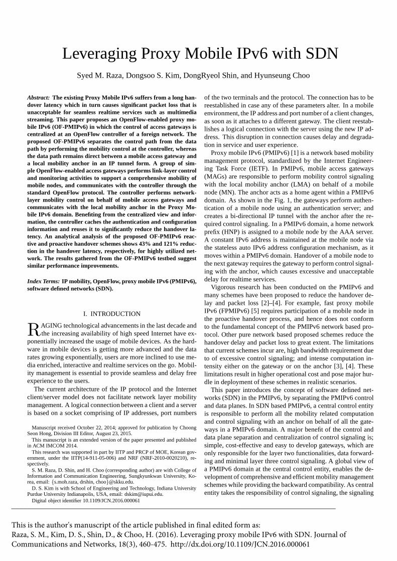
Proxy mobile IPv6 (PMIPv6) [1] is a network based mobilitymanagement protocol, standardized by the Internet Engineer-ing Task Force (IETF). In PMIPv6, mobile access gateways(MAGs) are responsible to perform mobility control signalingwith the local mobility anchor (LMA) on behalf of a mobilenode (MN). The anchor acts as a home agent within a PMIPv6domain. As shown in the Fig. 1, the gateways perform authen-tication of a mobile node using an authentication server; andcreates a bi-directional IP tunnel with the anchor after the re-quired control signaling. In a PMIPv6 domain, a home networkprefix (HNP) is assigned to a mobile node by the AAA server.A constant IPv6 address is maintained at the mobile node viathe stateless auto IPv6 address configuration mechanism, as itmoves within a PMIPv6 domain. Handover of a mobile node tothe next gateway requires the gateway to perform control signal-ing with the anchor, which causes excessive and unacceptabledelay for realtime services.
Vigorous research has been conducted on the PMIPv6 andmany schemes have been proposed to reduce the handover de-lay and packet loss [2]–[4]. For example, fast proxy mobileIPv6 (FPMIPv6) [5] requires participation of a mobile node inthe proactive handover process, and hence does not conformto the fundamental concept of the PMIPv6 network based pro-tocol. Other pure network based proposed schemes reduce thehandover delay and packet loss to great extent. The limitationsthat current schemes incur are, high bandwidth requirement dueto of excessive control signaling; and intense computation in-tensity either on the gateway or on the anchor [3], [4]. Theselimitations result in higher operational cost and pose major hur-dle in deployment of these schemes in realistic scenarios.
This paper introduces the concept of software defined net-works (SDN) in the PMIPv6, by separating the PMIPv6 controland data planes. In SDN based PMIPv6, a central control entityis responsible to perform all the mobility related computationand control signaling with an anchor on behalf of all the gate-ways in a PMIPv6 domain. A major benefit of the control anddata plane separation and centralization of control signaling is;simple, cost-effective and easy to develop gateways, which areonly responsible for the layer two functionalities, data forward-ing and minimal layer three control signaling. A global view ofa PMIPv6 domain at the central control entity, enables the de-velopment of comprehensive and efficient mobility managementschemes while providing the backward compatibility. As centralentity takes the responsibility of control signaling, the signaling
_________________________________________________________________________________
This is the author's manuscript of the article published in final edited form as:Raza, S. M., Kim, D. S., Shin, D., & Choo, H. (2016). Leveraging proxy mobile IPv6 with SDN. Journal of Communications and Networks, 18(3), 460-475. http://dx.doi.org/10.1109/JCN.2016.000061
overhead at the gateways and the anchor reduces in comparisonwith the other schemes, and management of the gateways be-come easier.
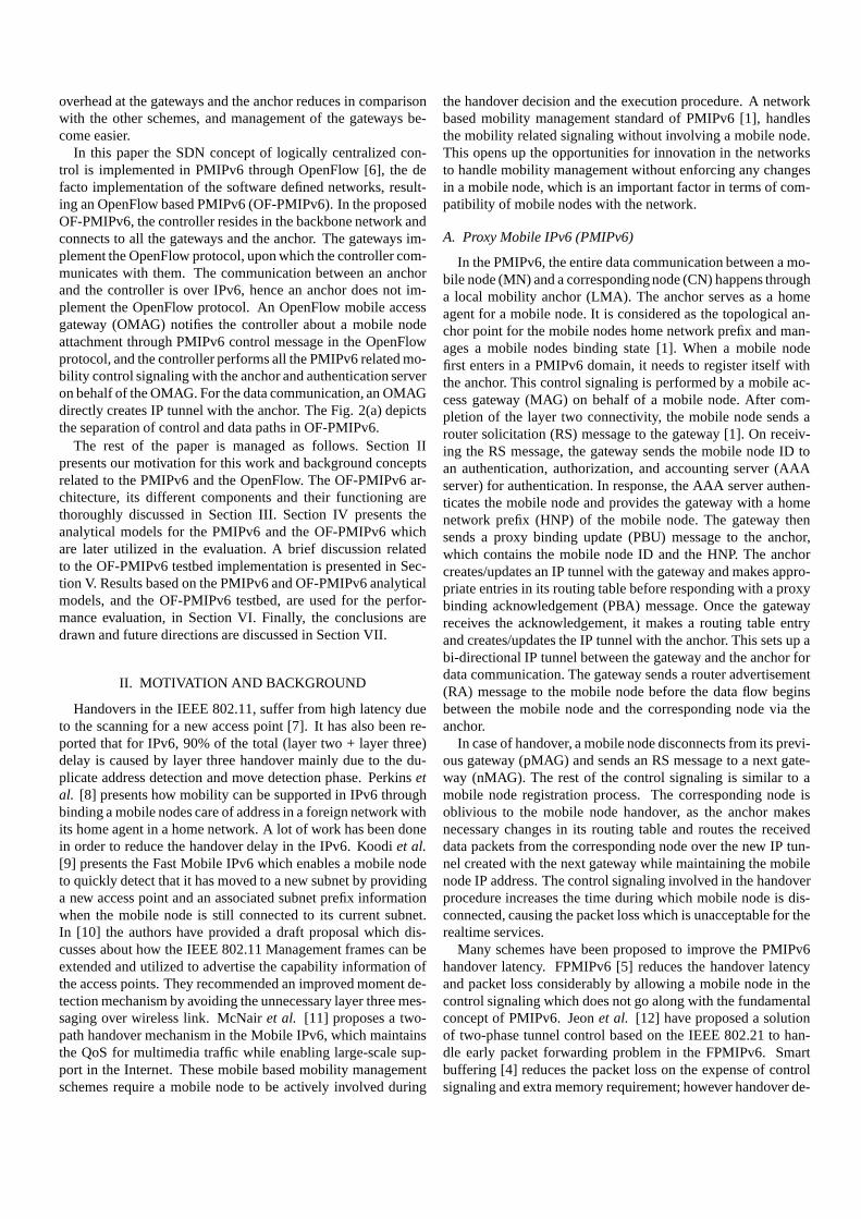
In this paper the SDN concept of logically centralized con-trol is implemented in PMIPv6 through OpenFlow [6], the defacto implementation of the software defined networks, result-ing an OpenFlow based PMIPv6 (OF-PMIPv6). In the proposedOF-PMIPv6, the controller resides in the backbone network andconnects to all the gateways and the anchor. The gateways im-plement the OpenFlow protocol, upon which the controller com-municates with them. The communication between an anchorand the controller is over IPv6, hence an anchor does not im-plement the OpenFlow protocol. An OpenFlow mobile accessgateway (OMAG) notifies the controller about a mobile nodeattachment through PMIPv6 control message in the OpenFlowprotocol, and the controller performs all the PMIPv6 related mo-bility control signaling with the anchor and authentication serveron behalf of the OMAG. For the data communication, an OMAGdirectly creates IP tunnel with the anchor. The Fig. 2(a) depictsthe separation of control and data paths in OF-PMIPv6.
The rest of the paper is managed as follows. Section IIpresents our motivation for this work and background conceptsrelated to the PMIPv6 and the OpenFlow. The OF-PMIPv6 ar-chitecture, its different components and their functioning arethoroughly discussed in Section III. Section IV presents theanalytical models for the PMIPv6 and the OF-PMIPv6 whichare later utilized in the evaluation. A brief discussion relatedto the OF-PMIPv6 testbed implementation is presented in Sec-tion V. Results based on the PMIPv6 and OF-PMIPv6 analyticalmodels, and the OF-PMIPv6 testbed, are used for the perfor-mance evaluation, in Section VI. Finally, the conclusions aredrawn and future directions are discussed in Section VII.
II. MOTIVATION AND BACKGROUND
Handovers in the IEEE 802.11, suffer from high latency dueto the scanning for a new access point [7]. It has also been re-ported that for IPv6, 90% of the total (layer two + layer three)delay is caused by layer three handover mainly due to the du-plicate address detection and move detection phase. Perkinsetal. [8] presents how mobility can be supported in IPv6 throughbinding a mobile nodes care of address in a foreign network withits home agent in a home network. A lot of work has been donein order to reduce the handover delay in the IPv6. Koodiet al.[9] presents the Fast Mobile IPv6 which enables a mobile nodeto quickly detect that it has moved to a new subnet by providinga new access point and an associated subnet prefix informationwhen the mobile node is still connected to its current subnet.In [10] the authors have provided a draft proposal which dis-cusses about how the IEEE 802.11 Management frames can beextended and utilized to advertise the capability information ofthe access points. They recommended an improved moment de-tection mechanism by avoiding the unnecessary layer three mes-saging over wireless link. McNairet al. [11] proposes a two-path handover mechanism in the Mobile IPv6, which maintainsthe QoS for multimedia traffic while enabling large-scale sup-port in the Internet. These mobile based mobility managementschemes require a mobile node to be actively involved during
the handover decision and the execution procedure. A networkbased mobility management standard of PMIPv6 [1], handlesthe mobility related signaling without involving a mobile node.This opens up the opportunities for innovation in the networksto handle mobility management without enforcing any changesin a mobile node, which is an important factor in terms of com-patibility of mobile nodes with the network.
A. Proxy Mobile IPv6 (PMIPv6)
In the PMIPv6, the entire data communication between a mo-bile node (MN) and a corresponding node (CN) happens througha local mobility anchor (LMA). The anchor serves as a homeagent for a mobile node. It is considered as the topological an-chor point for the mobile nodes home network prefix and man-ages a mobile nodes binding state [1]. When a mobile nodefirst enters in a PMIPv6 domain, it needs to register itself withthe anchor. This control signaling is performed by a mobile ac-cess gateway (MAG) on behalf of a mobile node. After com-pletion of the layer two connectivity, the mobile node sends arouter solicitation (RS) message to the gateway [1]. On receiv-ing the RS message, the gateway sends the mobile node ID toan authentication, authorization, and accounting server (AAAserver) for authentication. In response, the AAA server authen-ticates the mobile node and provides the gateway with a homenetwork prefix (HNP) of the mobile node. The gateway thensends a proxy binding update (PBU) message to the anchor,which contains the mobile node ID and the HNP. The anchorcreates/updates an IP tunnel with the gateway and makes appro-priate entries in its routing table before responding with a proxybinding acknowledgement (PBA) message. Once the gatewayreceives the acknowledgement, it makes a routing table entryand creates/updates the IP tunnel with the anchor. This sets up abi-directional IP tunnel between the gateway and the anchor fordata communication. The gateway sends a router advertisement(RA) message to the mobile node before the data flow beginsbetween the mobile node and the corresponding node via theanchor.
In case of handover, a mobile node disconnects from its previ-ous gateway (pMAG) and sends an RS message to a next gate-way (nMAG). The rest of the control signaling is similar to amobile node registration process. The corresponding node isoblivious to the mobile node handover, as the anchor makesnecessary changes in its routing table and routes the receiveddata packets from the corresponding node over the new IP tun-nel created with the next gateway while maintaining the mobilenode IP address. The control signaling involved in the handoverprocedure increases the time during which mobile node is dis-connected, causing the packet loss which is unacceptable for therealtime services.
Many schemes have been proposed to improve the PMIPv6handover latency. FPMIPv6 [5] reduces the handover latencyand packet loss considerably by allowing a mobile node in thecontrol signaling which does not go along with the fundamentalconcept of PMIPv6. Jeonet al. [12] have proposed a solutionof two-phase tunnel control based on the IEEE 802.21 to han-dle early packet forwarding problem in the FPMIPv6. Smartbuffering [4] reduces the packet loss on the expense of controlsignaling and extra memory requirement; however handover de-
MN movement
Control signalingData
IP data tunnel
Backbone network
Network X
CNInternet
LMA / AAA
nMAG pMAG
(a)
MN pMAG AAA LMA CN
DataData Tunnel data
RSAAA Req
AAA Res
PBU
PBA
RA
(b)
Fig. 1. PMIPv6 architecture and signaling call flow: (a) PMIPv6 architecture and (b) mobile node registration signaling call flow.
lay remains same as the standard PMIPv6. Kimet al. [2] pro-posed a solution to mitigate the packet loss during the handoverin PMIPv6 by introducing a buffering mechanism at the anchor,requiring larger buffering space at the anchor to cater the needsof all the mobile nodes for a large scale network. Ohet al. [3]also proposed a mechanism to relieve the packet loss during thehandover by buffering the packets at the optical buffering mod-ule of the anchor and reduces the handover latency as well bysimplifying the authentication mechanism during the PMIPv6handover process.
B. OpenFlow
The concept of SDN has been floating in the academic circlesfor a long time, and OpenFlow (OF) [6] has recently emerged asthe first implementation of SDN. The initial motivation for theOpenFlow was to enable researchers to perform their researchon real production networks. Later, OpenFlow is standardizedby the open networking foundation (ONF) [13]. A central con-trol entity in the OpenFlow network is known as controller. TheOpenFlow has been opted to implement the SDN concept in dif-ferent types of networks, e.g., wireless sensor networks, meshnetworks, data centers, etc. These networks consist of a set ofOF-enabled network devices (switch/router/access point) and acontroller. A network device consists of a data plane and a con-trol plane. The data plane is responsible for packet forwardingwhereas the control plane takes care of communication betweenthe OF switch and the controller over a secure TCP connec-tion. The main objective is to make the network control func-tions more centralized rather than distributed. The controllerperforms all the control logic and manages all the forwardingelements using the OF protocol. The OF switch consists of aflow table which performs packet lookup and forwarding. Anentry in a flow table consists of three main fields, header, ac-tion and statistics. Any incoming packet is matched against theheader fields of the entries in the flow table; if the match is foundthen action mentioned in the action field of the matched entry isperformed. In case of no match (table miss) the packet is sent tothe controller which installs a new flow entry in the flow tablecorresponding to that packet.
III. PROPOSED OF-PMIPV6 ARCHITECTURE
This paper proposes the OF-PMIPv6 architecture, which in-tegrates the OpenFlow with the PMIPv6 without modifica-tions. The mobile access gateways in the OF-PMIPv6 (OMAG)are only responsible for the layer two functionalities, while thelayer three related PMIPv6 control signaling is taken care bythe central controller. Our design of the OF-PMIPv6 architec-ture is motivated by a low handover latency, reduced packetloss, simplicity, extensibility, scalability, sustainability, compat-ibility with the existing PMIPv6 and scalability. The proactivescheme in the proposed architecture needs to achieve the han-dover latency and the packet loss within an acceptable rangefor realtime services, while not burdening the gateways and theanchor with the extensive control signaling. The proposed archi-tecture should be easily extensible to incorporate different mo-bility management schemes for reducing the handover latencyand the packet loss, and should provide scalability for addi-tion/removal of different network elements. Sustainability andcompatibility are key design features, where the proposed archi-tecture should cater the requirements of the production networkand should work with the standard PMIPv6 [1] as well.
In the OF-PMIPv6 architecture the OMAGs are consideredas the access network to which a mobile node makes the layertwo attachment and they also serve as a gateway for a mo-bile node. Over the wired link, OMAGs perform the PMIPv6control signaling with the controller in the backbone/core net-work of the service provider. The anchor and the AAA serverresides in the home network of a mobile node. On behalf ofthe OMAGs the controller performs the PMIPv6 control sig-naling with the anchor and the AAA server and this commu-nication travels through either the home network of the serviceprovider or any foreign network, presented as network ‘X’ inthe Fig. 2(a). Bi-directional IP data tunnel is created betweenthe anchor and the OMAG for the transmission of data pack-ets. The Fig. 2(a) presents the architecture of the OF-PMIPv6where the control signaling is through the controller, and thedata transmission is through the IP tunnel between the OMAGsand the anchor. The Fig. 2(b) shows the signaling call flow forthe mobile node registration in the OF-PMIPv6.
Control signaling
DataControl signaling over OpenFlow
IP data tunnel
MN movement
Backbone network
Network X
CNInternet
LMA / AAA
Controller
nOMAGpOMAG
(a)
MN pOMAG AAA LMA CN
DataData Tunnel data
Controller
RS
OF-RSAAA Req
AAA Res
PBU
PBA
OF-RARA
OpenFlow messages
Legend:
Tunnel_init
(b)
Fig. 2. OF-PMIPv6 architecture and signaling call flow: (a) OF-PMIPv6 architecture and (b) mobile node registration signaling call flow.
Both the control signaling and the data communication in thePMIPv6 takes place over the same path between the gatewayand the anchor. The OF-PMIPv6 separates the control signal-ing path from the data communication path. The controller per-forms the PMIPv6 control signaling with the anchor/AAA onbehalf of all the OMAGs, thereby logically virtualizing the mul-tiple OMAGs as one OMAG, therefore we consider it as a virtualmobility access gateway (vMAG). Communication between theOMAGs and the vMAG (in the controller) is over the OpenFlowprotocol. This logical separation of the paths is evident from theFig. 2(a). As the control signaling has been offloaded from theOMAGs to the controller, the OMAGs are mainly responsiblefor layer two functionalities and IP tunnel management.
A. OF-PMIPv6 Components
A.1 OpenFlow Enabled Mobile Access Gateway (OMAG)
In comparison with PMIPv6, an OMAG is the main evolvedcomponent in the OF-PMIPv6. The OMAGs responsibility ofthe PMIPv6 control signaling with the anchor is offloaded tothe controller, and the OMAG communicates with the controllerover the OF protocol. Therefore, the main functionalities ofan OMAG are layer two forwarding of data packets, IP tunnelmanagement and MNs link state monitoring for the proactivescheme.Link State Monitoring:
An OMAG monitors the link state of the mobile nodes at-tached to it, by recording the received signal strength (RSS)value of the arrived beacon or any other frames/packets. AnOMAG also samples the RSS values of the mobile nodes thatare not attached to the OMAG, by overhearing their com-munication. In single sample OMAG can receive multipleframes/packets from a mobile node. These link state values aremaintained as a moving average, and are reported to the con-troller in case of an event. The event occurs when the link stateof a mobile node crosses over either a lower threshold (too bad)or a higher threshold (too good). Appropriately weighted mov-ing average of the link state values and the two thresholds ensurethat the controller is not overwhelmed by the link state values,and enable the controller to make handover decision in proactive
scheme with reasonable accuracy, and prevents the system to be-come unstable through the ping pong effect. To monitor the linkstate of the mobile nodes which are not attached to the OMAG,monitor mode of the IEEE 802.11 is utilized.OpenFlow Protocol:
An OMAG implements the OF protocol, to communicate themobile node link state values and the PMIPv6 related signal-ing to the controller. The standard OF protocol does not sup-port PMIPv6 related control signaling. An experimenter mes-sage type is provided in the OF protocol to facilitate the additionof new message types and support for other protocols. The ex-perimenter message type is used in the OF-PMIPv6, to providesupport for the PMIPv6 control signaling. This extension of theOF protocol includes three new messages (Tunnelinit, S Reportand L Report). The controller sends the Tunnelinit message tothe next OMAG (nOMAG) in the reactive/proactive handover,to initiate an IP tunnel from the next OMAG to the anchor. TheOMAGs report mobile nodes link state to the controller throughS Report message. The OMAGs uses the LReport message tosend the lost report to the controller, if no signal is received froma mobile node for a certain period.Tunnel Management:
From the PMIPv6 perspective, the main responsibility ofan OMAG is to maintain the status of IP tunnels between anOMAG and the anchor for each associated mobile node. In theproactive OF-PMIPv6 scheme an OMAG maintains the status ofIP tunnel for a mobile node as provisional or conclusive. Whenthe tunnel status is provisional for a particular mobile node, theOMAG buffers the data packets received from the IP tunnel forthat mobile node, without forwarding them to the mobile node.These buffered data packets along with the normally receiveddata packets are forwarded to the mobile node without bufferingonce the status is changed to conclusive.
A.2 OpenFlow Controller
The controller resides in the backbone network as presentedin Fig. 2(a). In OF-PMIPv6 the controller acts as a central con-trol entity and performs the PMIPv6 related control signalingwith the anchor on behalf of all the OMAGs in the OF-PMIPv6

MN pOMAG LMA CN
Bi-direc!on tunnel created
nOMAG Controller
DataDataTunnel data
Disconnect
RSOF-RS
PBU
PBA
OF-RA
RA
Data Tunnel data
OpenFlow messages
Legend:
Packet
loss
Han
dove
r d
elay
Self-authentication
Tunnel_init
Data
Fig. 3. Reactive OF-PMIPv6 handover signaling call flow.
domain, therefore it requires to communicate both with theOMAGs and the anchor. The controllers in built modules takescare of much of the OpenFlow communication with the OMAG,however newly added OF-PMIPv6 modules are required to sup-port the mobility related communication with the OMAG andthe anchor. The controller has a complete view of entire net-work and the added OF-PMIPv6 mobility management moduleutilizes this information to perform the reactive and the proac-tive handovers while maintaining the proper state of a mobilenode through the finite state machines.OpenFlow Module:
OpenFlow module is responsible for communicating thePMIPv6 control and mobility related messages with OMAG,by using under-laying in-built functions of the controller. TheOpenFlow module also facilitates communication between dif-ferent OF-PMIPv6 modules in the controller. The main purposeof the OF protocol is to handle the forwarding plane of the net-work elements, and offers no support for the mobility manage-ment. The experimenter message type of the OF protocol is usedto provide required support for the OF-PMIPv6 control signal-ing between the controller and OMAGs, which is handled by theOpenFlow module in the controller.PMIPv6 Module:
The PMIPv6 module is responsible for performing standardPMIPv6 control signaling with the anchor and the AAA server.On directions from the OpenFlow module, it constructs thePMIPv6 message (e.g., PBU message) accordingly and sendsit to the anchor or the AAA server. Similarly it provides the re-quired information to the OpenFlow module once a response isreceived from the anchor or the AAA server.Mobility Management Module:
Mobility Management module consists of a connectivitydatabase (C-DB) which maintains the information of the mo-bile nodes such as MN ID, LMA ID, attached OMAG ID andMN link state values from different OMAGs. For each link statevalue, a timestamp is also recorded and is considered expired
after a particular time period. Once all the link state values fora mobile node are expired then it is considered to have left theOF-PMIPv6 domain. To perform the proactive handover, thelink state values in the C-DB are utilized to determine the han-dover initiation instant and the next OMAG. During the reactiveor proactive handover the proper state of a mobile node is main-tained in the mobility management module.
B. Operation of OF-PMIPv6
A mobile node registration and handover are two major oper-ations of the OF-PMIPv6. Upon entering the OF-PMIPv6 do-main, a mobile node associates itself to an OMAG and sendsa RS message. The OMAG forwards the RS message to thecontroller via OF protocol (OF-RS message). The controller ex-tracts the mobile ID from the OF-RS message. On finding noentry against the received mobile node ID in the C-DB, the con-troller sends it to the AAA server for authentication. The AAAserver authenticates the mobile node ID and provides the home-network prefix (HNP) of the mobile node to the controller. Us-ing the received HNP, the controller sends a PBU message tothe anchor. In the PMIPv6, a PBU message contains the mobilenode ID and the mobile node HNP, whereas in the OF-PMIPv6,a PBU message also contains the OMAG ID from whom theRS message is received, as the anchor is required to create anIP tunnel between itself and the OMAG. After making the rout-ing table entries, the anchor replies to the controller with a PBAmessage. On receiving the PBA message, the controller sendsa message to the OMAG for creation of an IP tunnel with theanchor. The OMAG updates its routing tables and creates theIP tunnel with the anchor if it does not exist already. Also thecontroller sends a RA message to the mobile node through theOMAG (OF-RA). The C-DB is updated with the information ofthe newly registered mobile node. Registration completes whenthe mobile node receives the RA message. The signal call flowpresented in the Fig. 2(b) shows the mobile node registrationprocedure.
In case of handover, the OF-PMIPv6 works either in reactiveor proactive mode depending on the controller and the OMAGconfiguration.
B.1 Mobile Node Handover in Reactive OF-PMIPv6
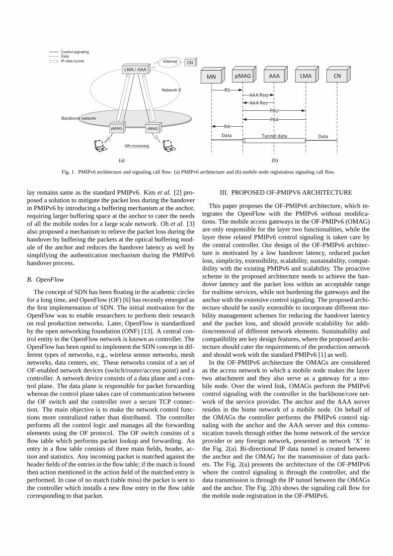
In the reactive OF-PMIPv6, the mobile node handover is al-most similar as handover in the PMIPv6 [1] with minor differ-ences. First is that upon receiving the RS message from a mo-bile node, the OMAG does not send the PBU message to theanchor, instead forwards the OF-RS message to the controller,and the controller takes care of rest of the control signaling withthe anchor which is similar to the mobile node registration pro-cedure in OF-PMIPv6. Secondly in PMIPv6 next gateway hasto re-authenticate the mobile node with the AAA server, as itcannot distinguish between a mobile node handover and regis-tration. This causes the increase in PMIPv6 handover latency.Re-authentication of a mobile node is not required in the reac-tive OF-PMIPv6, because of the cached mobile node informa-tion in the C-DB., and this is presented in the Fig. 3 throughSelf-Authentication internal message in the controller.
To make sure that there is no bogus mobile node record inthe C-DB, the controller only keeps the record of those mobilenodes which are connected with the OF-PMIPv6 network at thegiven time. In the reactive mode correct state of the C-DB isensured through the mobile node lost report sent by the OMAG,as in the reactive mode there are no link state messages. Themobile node connection lost report triggers a timer (validationtimer) at the controller, and if the controller does not receive thesame mobile nodes RS message from the other OMAG beforethe expiration of validation timer the mobile node record is re-moved, otherwise it is kept. Exclusion of the re-authenticationprocess, reduces handover latency in the reactive OF-PMIPv6comparing to PMIPv6. It is important to note that the controllersinternal Self-Authentication message does not imply that someauthentication protocol or algorithm is incorporated.
B.2 Mobile Node Handover in Proactive OF-PMIPv6
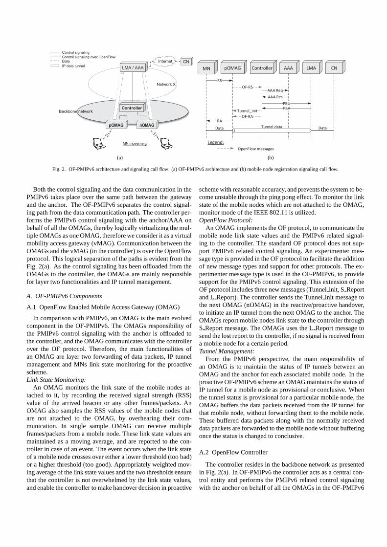
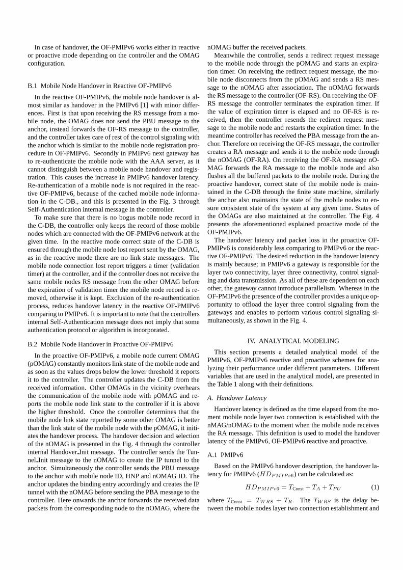
In the proactive OF-PMIPv6, a mobile node current OMAG(pOMAG) constantly monitors link state of the mobile node andas soon as the values drops below the lower threshold it reportsit to the controller. The controller updates the C-DB from thereceived information. Other OMAGs in the vicinity overhearsthe communication of the mobile node with pOMAG and re-ports the mobile node link state to the controller if it is abovethe higher threshold. Once the controller determines that themobile node link state reported by some other OMAG is betterthan the link state of the mobile node with the pOMAG, it initi-ates the handover process. The handover decision and selectionof the nOMAG is presented in the Fig. 4 through the controllerinternal HandoverInit message. The controller sends the Tun-nel Init message to the nOMAG to create the IP tunnel to theanchor. Simultaneously the controller sends the PBU messageto the anchor with mobile node ID, HNP and nOMAG ID. Theanchor updates the binding entry accordingly and creates the IPtunnel with the nOMAG before sending the PBA message to thecontroller. Here onwards the anchor forwards the received datapackets from the corresponding node to the nOMAG, where the
nOMAG buffer the received packets.Meanwhile the controller, sends a redirect request message
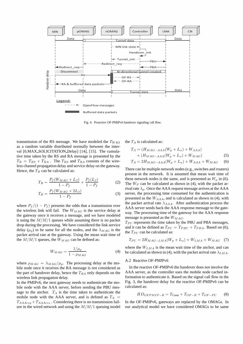
to the mobile node through the pOMAG and starts an expira-tion timer. On receiving the redirect request message, the mo-bile node disconnects from the pOMAG and sends a RS mes-sage to the nOMAG after association. The nOMAG forwardsthe RS message to the controller (OF-RS). On receiving the OF-RS message the controller terminates the expiration timer. Ifthe value of expiration timer is elapsed and no OF-RS is re-ceived, then the controller resends the redirect request mes-sage to the mobile node and restarts the expiration timer. In themeantime controller has received the PBA message from the an-chor. Therefore on receiving the OF-RS message, the controllercreates a RA message and sends it to the mobile node throughthe nOMAG (OF-RA). On receiving the OF-RA message nO-MAG forwards the RA message to the mobile node and alsoflushes all the buffered packets to the mobile node. During theproactive handover, correct state of the mobile node is main-tained in the C-DB through the finite state machine, similarlythe anchor also maintains the state of the mobile nodes to en-sure consistent state of the system at any given time. States ofthe OMAGs are also maintained at the controller. The Fig. 4presents the aforementioned explained proactive mode of theOF-PMIPv6.
The handover latency and packet loss in the proactive OF-PMIPv6 is considerably less comparing to PMIPv6 or the reac-tive OF-PMIPv6. The desired reduction in the handover latencyis mainly because; in PMIPv6 a gateway is responsible for thelayer two connectivity, layer three connectivity, control signal-ing and data transmission. As all of these are dependent on eachother, the gateway cannot introduce parallelism. Whereas in theOF-PMIPv6 the presence of the controller provides a unique op-portunity to offload the layer three control signaling from thegateways and enables to perform various control signaling si-multaneously, as shown in the Fig. 4.
IV. ANALYTICAL MODELING
This section presents a detailed analytical model of thePMIPv6, OF-PMIPv6 reactive and proactive schemes for ana-lyzing their performance under different parameters. Differentvariables that are used in the analytical model, are presented inthe Table 1 along with their definitions.
A. Handover Latency
Handover latency is defined as the time elapsed from the mo-ment mobile node layer two connection is established with thenMAG/nOMAG to the moment when the mobile node receivesthe RA message. This definition is used to model the handoverlatency of the PMIPv6, OF-PMIPv6 reactive and proactive.
A.1 PMIPv6
Based on the PMIPv6 handover description, the handover la-tency for PMIPv6 (HDPMIPv6) can be calculated as:
HDPMIPv6 = TConst+ TA + TPU (1)
whereTConst = TWRS + TR. The TWRS is the delay be-tween the mobile nodes layer two connection establishment and
MN pOMAG LMA CNnOMAG Controller
DataDataTunnel data
Handover_Init
Disconnect
RS
MN link state
OF-RS
RA & buffered data packets
Redirect_req
Redirect_req
Tunnel_init
OF-RA
Bi-direc"onal tunnel created
DataDataTunnel data
OpenFlow messages
Buffered data packets
Legend:
PBA
PBU
Han
dove
r de
lay
Fig. 4. Proactive OF-PMIPv6 handover signaling call flow.
transmission of the RS message. We have modeled theTWRS
as a random variable distributed normally between the inter-val [0,MAX SOLICITATION Delay] [14], [15]. The cumula-tive time taken by the RS and RA message is presented by theTR = TRS + TRA . TheTRS andTRA consists of the wire-less channel propagation delay and service delay on the gateway.Hence, theTR can be calculated as:
TR =Pf (WMAG + Lβ)
1− Pf
+Pf (Lβ)
1− Pf
(2)
TR =Pf (WMAG + 2Lβ)
1− Pf
(3)
wherePf/(1 − Pf ) presents the odds that a transmission overthe wireless link will fail. TheWMAG is the service delay atthe gateway once it receives a message, and we have modeledit using theM/M/1 queues while assuming there is no packetdrop during the processing. We have considered the link servicedelay (µp) to be same for all the nodes, and theλMAG is thepacket arrival rate at the gateway. Using the mean wait time oftheM/M/1 queues, theWMAG can be defined as:
WMAG =1/µp
1− ρMAG
(4)
whereρMAG = λMAG/µp. The processing delay at the mo-bile node once it receives the RA message is not considered asthe part of handover delay, hence theTRA only depends on thewireless link propagation delay.In the PMIPv6, the next gateway needs to authenticate the mo-bile node with the AAA server, before sending the PBU mes-sage to the anchor.TA is the time taken to authenticate themobile node with the AAA server, and is defined asTA =TAAAreq+TAAAres . Considering there is no transmission fail-ure in the wired network and using theM/M/1 queuing model
theTA is calculated as:
TA = (HMAG−AAA(Wp + Lα) +WAAA)
+ (HMAG−AAA(Wp + Lα) +WMAG) (5)
TA = 2HMAG−AAA(Wp + Lα) +WAAA +WMAG (6)
There can be multiple network nodes (e.g., switches and routers)present in the network. It is assumed that mean wait time ofthese network nodes is the same, and is presented asWp in (6).TheWP can be calculated as shown in (4), with the packet ar-rival rateλp. Once the AAA request message arrives at the AAAserver, the processing time consumed for the authentication ispresented as theWAAA, and is calculated as shown in (4), withthe packet arrival rateλAAA. After authentication process theAAA server sends back the AAA response message to the gate-way. The processing time of the gateway for the AAA responsemessage is presented as theWMAG.TPU represents the time taken by the PBU and PBA messages,and it can be defined asTPU = TPBU + TPBA. Based on (6),theTPU can be calculated as:
TPU = 2HMAG−LMA(Wp + Lα) +WLMA +WMAG (7)
where theWLMA is the mean wait time of the anchor, and canbe calculated as shown in (4), with the packet arrival rateλLMA.
A.2 Reactive OF-PMIPv6
In the reactive OF-PMIPv6 the handover does not involve theAAA server, as the controller uses the mobile node cached in-formation to authenticate it. Based on the signal call flow in theFig. 3, the handover delay for the reactive OF-PMIPv6 can becalculated as:
HDOFPMIP−R = TConst+ TOF−R + TOF−PU (8)
In the OF-PMIPv6, gateways are replaced by the OMAGs. Inour analytical model we have considered OMAGs to be same

Controller
send
Tunnel_init
and OF-DISC
OMAG
send RA
MN
receives
RA
L2 Link
down
with
pOMAG
OMAG send
OF-RSL2 Link
up with
nOMAG
MN
send
RS
OMAG
send
Redirect
Req
LMA send
PBA
Controller
send PBU
Controller
receives
OF-RS
Controller
sends
OF-RA
Fig. 5. OF-PMIPv6 proactive handover timing diagram.
as gateways in terms of their processing delay. Hence, theTConst
and theWMAG in the OF-PMIPv6 remains same as the PMIPv6.The communication delay between the OMAG and the con-troller is encompassed by theTOF−R, which can be definedas:TOF−R = TOF−RS + TOF−RA. Based on (5) theTOF−R
can be calculated as:
TOF−R = 2HMAG−CON(Wp +Lα) +WCON +WMAG (9)
where theWCON is the mean wait time of the controller, andcan be calculated as shown in (4), with the packet arrival rateλCON .
In the OF-PMIPv6, the controller is responsible to communi-cate with the anchor on behalf of the OMAGs. TheTOF−PU
represents the communication delay between the controller andthe anchor, and can be defined as:TOF−PU = TOF−PBU +TOF−PBA. Similar to (9), theTOF−PU can be calculated as:
TOF−PU = 2HCON−LMA(Wp + Lα) +WCON +WLMA.(10)
A.3 Proactive OF-PMIPv6
Unlike the PMIPv6 and the reactive OF-PMIPv6, in theproactive OF-PMIPv6, a mobile node initiates the handover onthe controller directive. The mobile node disassociates with thepOMAG because of the redirect request message from the con-troller. The handover start point is same as in the PMIPv6 andthe OF-PMIPv6 reactive. The handover delay for the proactiveOF-PMIPv6 can be calculated as:
HDOFPMIP−P = TConst+ TOF−R + THO−Wait. (11)
As shown in the Fig. 5, the controller in proactive mode com-municates with the nOMAG, anchor and a mobile node with-out waiting for the response from the first. The controller firstof all sends the tunnelinit message to the nOMAG, then sends
the PBU message to the anchor and while waiting for the PBAmessage it sends the redirect request message to the mobilenode through the pOMAG. This simultaneous communicationenables us to reduce the handover delay, because when the con-troller receives the OF-RS message from the nOMAG it havealready finished its communication with anchor and right awaysends the OF-RA message. However, there can be a case wherecontroller is still waiting for a PBA message from the anchorwhen it receives an OF-RS message from the nOMAG. Thiscase only occurs when the anchor is located at far off destinationwith large communication delay with the controller, and in thiscase the controller takes extra time in dispatching the OF-RAmessage to the nOMAG. This extra wait time is expressed astheTHO−Wait in (11) and can be calculated as:
THO−Wait = MAX [TRR−OFRS , TOF−PU ]− TRR−OFRS .(12)
The time elapsed between the redirect message sent from thecontroller and the OF-RS message received at the controlleris expressed as theTRR−OFRS . If the TRR−OFRS is greaterthanTOF−PU , it means that the controller will have the OF-RA message ready once it receives the OF-RS message fromthe nOMAG and in this case theTHO−Wait will be zero. Ifthe TOF−PU is greater than theTRR−OFRS , in this case theTHO−Wait = TOF−PU − TRR−OFRS . TheTRR−OFRS can becalculated as:
TRR−OFRS = TDISC +TL2+TWRS +TRS+TOF−RS (13)
where theTDISC is the delay for redirect request message toreach the mobile node from the controller via the pOMAG, andcan be calculated as:TDISC = TOF−RR + TRR. The delayof redirect request message from the controller to the pOMAGis expressed as theTOF−RR and is same as theTOF−RA. Thedelay from the pOMAG to the mobile node is expressed as theTRR and is same as theTRA.
B. Registration Latency
When a mobile node enters in the PMIPv6 domain, it registersitself with the anchor by sending an RS message to the gateway.The registration latency is defined as the time elapsed from themoment mobile nodes layer two connection is established to themoment when it receives the RA message. In the PMIPv6, theregistration latency is similar to the handover latency. Whereas,in the OF-PMIPv6 the registration latency is slightly more thanthe handover latency, because of the authentication process. Theregistration latency in the OF-PMIPv6 can be calculated as:
RDOFPMIP = HDOFPMIP−R + TOF−A (14)
where theTOF−A is the communication delay between the con-troller and the AAA server, and can be calculated as:
TOF−A = 2HCON−AAA(Wp+Lα)+WCON +WAAA. (15)
C. Buffering Cost
Buffering of the data packets is required to minimize thepacket loss which might occur during the mobile nodes han-dover. The space required for the buffering is referred to asbuffering cost. Depending on the scheme in use, buffering ofthe data packets is generally performed either on the pMAG ornMAG during a handover process, and buffered data packets areforwarded to the mobile node by the pMAG or nMAG upon itsattachment to an nMAG.
The standard PMIPv6 [1] does not provide buffering mecha-nism and so does the OF-PMIPv6 in the reactive mode, becausethe identity of the nOMAG is not known before the handoverand there is no communication between the pOMAG and thenOMAG. However, in the OF-PMIPv6 proactive mode identityof the nOMAG is known to the controller and hence the buffer-ing is performed at the nOMAG to minimize the packet losswhich might occur during the handover. Buffering for a mobilenode starts at the nOMAG on the completion of the bidirectionaltunnel between itself and the anchor, and continues until it re-ceives the OF-RA message from the controller.
The required space for a mobile node at the nOMAG is theaccumulative size of the data packets received at the nOMAG inthe time period starting from the arrival of the PBU message atthe anchor with the nOMAG ID and ending when the nOMAGreceives the OF-RA message from the controller. For a mobilenode proactive handover in the OF-PMIPv6, the buffering costcan be calculated as:
BCOFPMIP−P = λsE(S)(TBUF−Wait) (16)
where theλs is the average session arrival rate and theE(S) isthe average session length [14]. TheTBUF−Wait is the durationfor which data packets are buffered at the nOMAG, and it isdefined as the difference between the buffering end time and thestart timeTBUF−Wait = TBE − TBS. The buffering end andstart time can be calculated as:
TBS = MAX [TOF−PU , TTun−init ] (17)
TBE = MAX[TRR−OFR
Pa
, TBS
]
(18)
where theTTun−init is the delay for the tunnel initiate mes-sage from the controller to the nOMAG, and is same as theTOF−RA. The time elapsed between the redirect request mes-sage sent from the controller and the OF-RA message receivedby the nOMAG is defined as theTRR−OFR, and is calculatedas:TRR−OFR = TRR−OFRS + TOF−RA.
The controller selects the nOMAG with the highest RSS valueat the time of handover initiation. On receiving the redirect re-quest message the mobile node disconnects itself from the pO-MAG and connects to the nOMAG with the highest RSS valueand is selected by the controller. In case where multiple candi-date nOMAGs are available with the same RSS value, the mo-bile node can attach to any one of them. The probability thatthe mobile node will attach to the nOMAG selected by the con-troller, when multiple candidate nOMAGs are available with thesame RSS value is presented byPa. Clearly, if the mobile nodeattaches to the nOMAG which is not selected by the controller,then buffering end time at the controller selected nOMAG willextend till infinity. Hence, the buffering end time is inverselyproportional to the success probability of the mobile node at-tachment to the controller selected nOMAG. ThePa dependson the number of candidate OMAGs, and it can be calculatedas:
Pa =1
N(19)
whereN is the number of candidate nOMAGs.
D. Packet Loss
During a handover the mobile node stops receiving thepackets as soon as it disconnects from the pMAG/pOMAG,and resumes after receiving the RA message from thenMAG/nOMAG. In our packet loss model we have not consid-ered the mobile nodes layer two connection establishment time.In case of no buffering mechanism the packets are lost duringthe handover. In PMIPv6 and reactive OF-PMIPv6 there is nobuffering mechanism, hence their packet loss can be calculatedas:
PLPMIPv6 = λsE(S)HDPMIPv6, (20)
PLOFPMIP−R = λsE(S)HDOFPMIP−R. (21)
In the proactive OF-PMIPv6 buffering is performed at the nO-MAG, however packet loss can occur if: 1) As a result of redirectrequest message, the mobile node disconnects from the pOMAGbefore the IP tunnel at the anchor is updated to the nOMAG, 2)the data packets reach the nOMAG through the tunnel but arenot buffered because the communication delay for tunnel initi-ate message is more thanTOF−PU . Once the buffering starts atthe nOMAG there is no further packet loss. When the nOMAGreceives the OF-RA message from the controller, it sends all thebuffered data packets along with the RA message to the mobilenode and starts forwarding the data packets to the mobile nodewithout buffering, therefore the packet loss for the proactive OF-PMIPv6 can be calculated as:
PLOFPMIP−P = λsE(S)(TTUD + TTID). (22)
Where theTTUD is the tunnel update delay at the anchor andrepresents the above mentioned case one for the packet loss. The

KOREN
Linux server ‘A’OF controller (NOX v1.3)
Linu
x se
rve
r ‘B’
Eth
0
OMAG
OMAG
IP tunnel
Control signaling
OpenFlow protocol
LMA
+
AAA
Eth 1
Eth 2
CN
RTNS
Data packets
Fig. 6. OF-PMIPv6 Testbed.
tunnel initiate delay at the nOMAG for the above mentionedcase two is expressed as theTTID. BothTTUD andTTID canbe calculated as:
TTUD = MAX [TDISC , TOF−PU ]− TDISC , (23)
TTID = MAX [TTun−init , TOF−PU ]− TOF−PU . (24)
As both the cases for packet loss does not depend on the as-sociation of the mobile node with the nOMAG, therefore theprobabilityPa does not apply on the packet loss.
V. IMPLEMENTATION
To evaluate the performance of the proposed schemes, an in-tegrated PMIPv6 and OpenFlow testbed is developed to advo-cate the feasibility, practicality and benefits of the OF-PMIPv6in the realistic situations of the production networks. The Fig. 6presents the architecture of the OF-PMIPv6 testbed. The Open-Flow version 1.3 [13] is used in the OF-PMIPv6 testbed, be-cause of its comprehensive support for IPv6. An open sourceimplementation by the Open Air Interface [16], is used for thePMIPv6 module in the controller and the anchor.
A. OMAG Implementation
The testbed currently has five OMAGs which are connectedto the KOREN (Korean advance research Network), which isan international research collaboration network, spreading overmultiple countries and continuously growing [17]. As presentedin the section 4.2.1 the OMAG is required to implement partialfunctionalities of the PMIPv6 gateway, a complete OF proto-col 1.3 and control messages which are not supported by theOF protocol. To suffice these requirements open source routerimplementation for embedded device (OpenWRT) [18] is de-ployed on the Alix 2d2 development kit [19]. An open sourceimplementation of the OF protocol v1.3 for the switches [20]is utilized on the OMAGs, and is extended through the experi-menter message type, to support the OF-PMIPv6 control signal-ing. The developed tunnel management module manages andcreates an IP in IP tunnel with the anchor and makes appropri-ate entries in the routing table (in Linux kernel), through which
user data is exchanged between the mobile node and the anchor.A link state monitoring module is developed in the user spaceof the OMAG to sample the RSS values of all the nearby mo-bile nodes by utilizing the monitor mode of the IEEE 802.11for a predefined sample duration. The collected link state infor-mation of the mobile nodes is sent to the controller using theS report type experimenter message.
B. OpenFlow Controller Implementation
The controller is a dedicated Linux server with 32 GB mem-ory, 2.5 TB hard disk and Intel Xeon CPU (3.10 GHz quadcore). The controller is connected to the KOREN and servesas a central control entity in the OF-PMIPv6. The open sourceimplementation of the NOX supporting OF protocol v1.3 [20]is used for the controller. The underlying library functions ofthe NOX are used to perform all the communication with theOMAG either through the standard OF protocol message typesor the experimenter message type. The OpenFlow module inthe controller subscribes with the event handlers in the NOXto receive the standard and experimenter OF protocol messagesfrom the OMAGs. The required standard OF protocol and exper-imenter messages are created in the OpenFlow module throughthe NOX library functions. To send the standard and exper-imenter OF protocol messages to the OMAG, the OpenFlowmodule utilizes the API functions exposed by the NOX. Themobility management module is developed as part of the Open-Flow module, and is used to store the OMAGs and mobile nodesinformation, as well as to maintain the mobile node state dur-ing the reactive or proactive handovers. The PMIPv6 module isused to communicate with the anchor. The Role of the PMIPv6module is to generate the PMIPv6 control messages from theinformation provided by the OpenFlow module, and send themto the anchor. Also, it provides the information to the OpenFlowmodule based on the response received from the anchor. ThePMIPv6 module executes as a separate process and communi-cates with the OpenFlow module through IPC.
State of the mobile node is maintained as not registered, al-ready registered or updated registration through the C-DB. TheOpenFlow module performs the mobile node state transition onreceiving the OF-PMIPv6 protocol messages.NOT REGISTERED: It occurs when a mobile node connects tothe OF-PMIPv6 domain and no prior entry exists in the C-DB.In response, the OF module creates a new entry for the mobilenode in the C-DB after the authentication with the AAA server,and via the PMIPv6 module communicate with the anchor inorder to establish the IP in IP tunnel. On receiving an acknowl-edgement from the anchor, the PMIPv6 module responds to theOF module with an RA message, which is then sent to the mo-bile node through the OMAG.ALREADY REGISTERED: It occurs when the controller re-ceives the RS message from the current OMAG of the alreadyregistered mobile node. In response, the controller simply re-sends the RA message to the mobile node via its current OMAG,as it already has the RA message in the C-DB.UPDATE REGISTRATION: If an entry for the mobile node al-ready exists in the C-DB for which the RS message is received,but the ID of the OMAG in the C-DB is not similar to the IDof the OMAG which has sent the OF-RS message, then this is

Table 1. Notation.
Variables Description Values
HMAG−AAA, HMAG−LMA,HMAG−CON
Number of hops between MAG and AAA server, LMA, Con-troller, respectively
[1]–[19]
HCON−LMA, HCON−AAANumber of hops between Controller and LMA, AAA server, re-spectively
[1]–[19]
µp Link service rate 10 Mbps
λp Packet arrival rate at the network nodes e.g., switches and routers 1–9 Mbps
λMAG, λLMA, λAAA, λCONPacket arrival rate at MAG, LMA, AAA and Controller, respec-tively
1–9 Mbps
λs Average session arrival rate 0.7
E(S) Average session length 20
ρp Utilization of network nodes e.g., switches and routers 0.1–0.9
ρMAG, ρLMA, ρAAA, ρCON Utilization of MAG, LMA, AAA and Controller, respectively 0.1–0.9
Lβ Wireless link propagation delay 15 ms
Lα = d/ωWired link propagation delay, where distance (d)=1500 m andlink speed (ω)= 2× 10⁸ m/s
0.0075 ms
Wp Mean wait time of the network nodes e.g., switches and routers–
WMAG,WLMA,WAAA,WCON
Mean wait time of the MAG,LMA,AAA and Controller, respec-tively
–
Pf Failure probability of wireless link 0.3
Pa Success probability of a mobile node attachment with nOMAG–
N Number of candidate nOMAGs 2
TL2 Time delay for establishing the layer two connection 450 ms
TWRSTime from established layer two connection to dispatch of firstRS message
220 ms
considered as the UPDATE REGISTRATION case. This caseoccurs when the mobile node handover from one OMAG to theother. In response, the information of the new OMAG is up-dated in the C-DB, the PMIPv6 module communicates with theanchor in order to update the IP in IP tunnel, and meanwhile theOF module sends the OF-RA message (which is already in theC-DB) and Tunnel-Init message to the new OMAG.
C. Real Time Network Simulator (RTNS)
The OF-PMIPv6 testbed aims to provide a realistic produc-tion network environment in which the anchor is usually presentin the mobile nodes home network along with the AAA server,and a corresponding node can be anywhere in the Internet. Todepict this we have developed a Real Time Network Simula-tor (RTNS) in NS-3, which emulates the background traffic andnetwork delay as experienced in the real network environment.The motivation behind the development of the RTNS module isto show the effectiveness of the proposed OF-PMIPv6 architec-ture under realistic scenarios, however it is not the integral partof the OF-PMIPv6 architecture of the OF-PMIPv6 testbed.
A virtual network in the RTNS connects to the outside worldthrough a TAP and Emu NetDevice of the NS-3. An Emu Net-Deivce connects to the real Ethernet card of the server [21]. Foran Emu NetDevice to receive the packets from the outside ofNS-3, the real Ethernet card is set to promiscuous mode and the
Ethernet device name (e.g., eth0) is provided to the Emu Net-Device. NS-3 utilizes the MAC addresses of the interfaces todistinguish between the real and emulated interfaces [22]. Toavoid the occurrence of packet duplication, the IP forwardingmust be disabled in the Linux system. In the RTNS, there aretwo border nodes and each border node has two interfaces, oneinterface is Emu Netdevice to connect to the real Ethernet card,and the other interface is to connect to the virtual network in theRTNS. A border node receives a packet on its Emu NetDeviceinterface from the Ethernet card and forwards it to the virtualnetwork through its other interface. In the virtual network thepackets are routed to the other border node which forwards themoutside to the real Ethernet card.
The RTNS runs on a dedicated Linux server, attached to theKOREN. The Linux server consists of 8 GB memory, 2.5 TBhard disk and an Intel CPU with quad cores where each corespeed is 3.10 GHz. As presented in the Fig. 6, the control mes-sages from the controller to the anchor and vice versa goesthrough the RTNS in order to introduce the real network de-lay. Similarly the IP in IP tunnel between the OMAG and theanchor goes through the RTNS, so the data packets experiencethe same delay as the control messages do. The anchor stripsoff the tunnel IP header from the data packets received throughthe IP in IP tunnel and forwards them back to the RTNS andthis time the RTNS forwards the data packets to the correspond-

Fig. 7. Handover latency comparison with increasing utilization of networkelements and PMIPv6/OF-PMIPv6 nodes.
ing node after introducing a corresponding delay, and the sameis performed in the reverse direction. In other words the RTNSworks as a router, but also introduces the delay in the packetsaccording to different realistic scenarios.
VI. PERFORMANCE EVALUATION
This section discusses the performance evaluation of the OF-PMIPv6 based on the analytical model and experimental resultsfrom the testbed.
A. Analytical Evaluation
Analytical evaluation between the PMIPv6 and the OF-PMIPv6 is drawn to show the performance gains of the reactiveand proactive schemes in OF-PMIPv6 over the PMIPv6. Thevalues of parameters presented in the Table 1 are used in theevaluation, unless stated otherwise [3], [23], and [24].
The layer two connection delay is heavily dependent on thehardware of wireless card in the mobile node and the OMAG[25], as different manufacturers follow different message se-quences and development techniques. For our analysis we haveconsidered the value ofTL2 averaged from the results presentedin [7], [25], and [26]. In all the performed evaluations, the AAAserver is considered to coexist with the anchor, hence the authen-tication delay is considered same as the binding update delay.
A.1 Handover Latency Comparison
Because of city wide WiFi deployments and exponentially in-creasing usage of the data over the mobile networks, the trafficload on the networks is increasing which also affects the han-dover performance. Based on the values in the Table 1 andin (1), (8), and (11), an analytical performance comparison forthe handover latency in the PMIPv6, reactive OF-PMIPv6 andproactive OF-PMIPv6 is presented in the Fig. 7, as a function ofnetwork utilization. A mobile node is considered to be in a for-eign network and the controller is present in the same backboneas the current OMAG, hence the number of MAG/Controller
to anchor hops and OMAG to Controller hops are set to be19 and 1, respectively. The results in the Fig. 7 show that thePMIPv6 handover latency exponentially increase with the in-crease in network utilization. The reactive OF-PMIPv6 followsthe same trend as the PMIPv6 but has 50% less handover la-tency. The proactive OF-PMIPv6 has a slight increase in thehandover latency because the communication delay with theanchor (TOF−PU ) becomes greater thanTRR−OFRS in (12),hence the controller has to wait extra time before sending theOF-RA message to the OMAG.
A distinguishing characteristic of the proposed OF-PMIPv6is its capability to sustain under the high network traffic loadand communication delays, where the PMIPv6 performance de-grades rapidly. The relative handover performance gain of theOF-PMIPv6 over the PMIPv6 is calculated as [15]:
PGOFPMIP−R =HDPMIPv6
HDOFPMIP−R
, (25)
PGOFPMIP−P =HDPMIPv6
HDOFPMIP−P
. (26)
Using (25) and (26), consolidated handover performance gainof the proposed OF-PMIPv6 reactive and proactive schemesagainst the increasing network utilization and the anchor dis-tance from the gateway/controller, is shown in the Figs. 8(a) and8(b), respectively. The increase in performance gain of the re-active OF-PMIPv6 is because of the cached mobile node infor-mation in the controller, and for the proactive OF-PMIPv6 theincreasing performance gain is the result of the preemptive han-dover decision by the controller and in advance control signal-ing. It can be inferred from the Figs. 8(a) and 8(b) that under re-alistic network scenarios the proposed OF-PMIPv6 shows highhandover performance gains over the PMIPv6.
A.2 MN Registration Latency Comparison
The MN registration process is similar in the both OF-PMIPv6 reactive and proactive mode, and has slightly higher la-tency than the standard PMIPv6 because of an extra control stepin form of the controller and the required authentication with theAAA server. Based on (14) the difference in registration laten-cies of the OF-PMIPv6 and the standard PMIPv6 is calculatedto be approx. 0.04sec and it remains constant for any value ofcommunication delay with the anchor. As the mobile node reg-isters only once upon its entry in the PMIPv6 or OF-PMIPv6domain, therefore this increase in delay is insignificant.
A.3 Packet Loss Comparison
The packet loss comparison is drawn between the PMIPv6and the proposed OF-PMIPv6 (reactive and proactive modes)based on (22), (23), and (24), respectively. The Fig. 9 shows thepacket loss comparison results as a function of network utiliza-tion. The average session length (E(S)) at the mobile node is setto be 20 packets, and the average session arrival rate (λs) is con-sidered as 0.7 sessions per second. Results in the Fig. 9 are mea-sured when the number of hops between the gateway/controllerand the anchor are set to be 19. The packet loss for the OF-PMIPv6 reactive and the standard PMIPv6 is directly propor-

1.0
1.1
1.2
1.3
1.4
1.5
1.6P
erf
orm
ance g
ain
Num
ber of hops
to L
MA
Network utilization
0.10.3
0.50.6
0.8
1
5
9
13
17
(a)
1.0
1.5
2.0
2.5
3.0
3.5
4.0
4.5
0.10.3
0.50.6
0.8
1
5
9
13
17
(b)
Fig. 8. OF-PMIPv6 relative handover performance gain over PMIPv6: (a) Reactive OF-PMIPv6 handover performance gain against network utilization anddistance from the anchor and (b) proactive OF-PMIPv6 handover performance gain against network utilization and distance from the anchor.
Fig. 9. Packet loss comparison results with increasing utilization of networkelements and PMIPv6/OF-PMIPv6 nodes.
tional to the handover latency as there is no buffering mecha-nism, therefore the PMIPv6 suffers with the maximum amountof packet loss as its handover latency is the largest. In the Fig. 9proactive OF-PMIPv6 show a gradual increase in the packet lossbecause of the early arrival of the redirect request message at themobile node, whereas the PBU message to the anchor is delayeddue to the multiple hops with high background traffic.
A.4 Control Signaling Comparison
The control signaling overhead of the proposed schemes isdefined as the number of extra bytes transmitted during the con-trol signaling, comparing to the control signaling in the stan-dard PMIPv6 handover. The Table 2 lists the control messagesand their sizes, which are transmitted in the PMIPv6 and in theproposed OF-PMIPv6 reactive and proactive schemes. The con-
trol message sizes mentioned in the Table 2 are based on thetraces obtained from the testbed. The AAA protocol used in thePMIPv6 is RADIUS. The AAA request/response message sizeis based on the access request and response message mentionedin the RFC 2865 [27]. Based on the Table 2, the number of bytestransmitted during the control signaling in the PMIPv6 handoverare 706 bytes, whereas in the reactive and proactive OF-PMIPv6handover transmitted control messages bytes are 1190 and 1362,respectively. For the proactive OF-PMIPv6, the link status mes-sage sent by the OMAG is not considered as part of the handoverprocess as it is not a handover trigger. A handover is initiatedby the controller, when it decides that better links are availablefor a mobile node. A link state message is sent to deliver themobile node link status value to the controller, and only whenan event is occurred on the OMAG. Size of a link state messageis approx. 300 bytes.
B. Experimental Evaluation
In the experimental evaluation we present the results for mo-bile node handover latency in the reactive OF-PMIPv6 scheme.The testbed is set up as described in the Fig. 6. The pOMAGand nOMAG are placed in a way that there is minimum foot-print overlap between the two OMAGs. A person holds the mo-bile node and moves from one OMAG to the other on a prede-fined path with walking speed. Initially the mobile node con-nects to the pOMAG and registers its self to the OF-PMIPv6domain. As the person walks away from the pOMAG and en-ters in footprint of the nOMAG, the mobile node disconnectsfrom the pOMAG and connects to the nOMAG. The handoverlatency of the mobile node in the reactive OF-PMIPv6 is calcu-lated as the time difference between the RS and RA messagessent and received by the mobile node, respectively. Delay be-tween the layer two connection establishment and transmissionof RS message (TWRS) is not considered while collecting thehandover results, because the value forTWRS is implementationdependent and differs for different operating systems and ven-

Table 2. Control messages and their sizes in PMIPv6 and OF-PMIPv6.
PMIPv6 Reactive OF-PMIPv6 Proactive OF-PMIPv6Message Size Message Size Message Size
RS 70 bytes RS 70 bytes PBU 156 bytes
AAArequest 120 bytes OF-RS 254 bytes Tunnel-init 266 bytes
AAAresponse 120 bytes OF-RA 204 bytes Redirect Req 172 bytes
PBU 156 bytes Tunnel-init 266 bytes PBA 130 bytes
PBA 130 bytes PBU 156 bytes RS 70 bytes
RA 110 bytes PBA 130 bytes OF-RS 254 bytes
RA 110 bytes OF-RA 204 bytes
RA 110 bytes
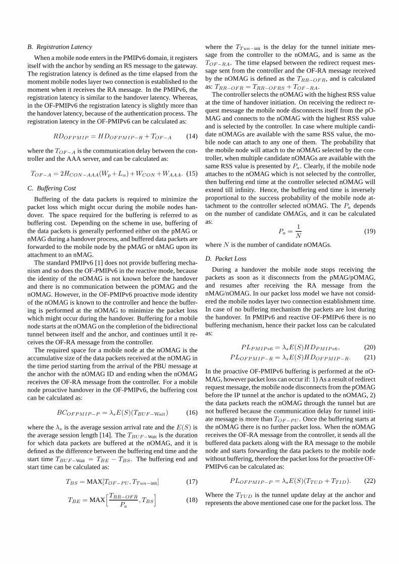
dors. However, to make the testbed results consistent with theanalytical model, value ofTWRS from the table 1 (220 ms) isadded in each testbed handover latency result. The reactive OF-PMIPv6 handover results from, the testbed and the analyticalmodel, are presented in the Fig. 10. The testbed results for thereactive OF-PMIPv6 handover are collected over a period of oneweek. For each day of the week 50 experiments are performed atthe similar time, and their average is considered as the handoverlatency for that day. The analytical model based reactive OF-PMIPv6 handover latency in the Fig. 10 considers, single hopbetween the OMAGs and the controller and four hops betweenthe controller and the anchor, with the utilization for all the OF-PMIPv6 nodes and the network node is 0.5. The results in theFig. 10 show that testbed results for the reactive OF-PMIPv6are close to the results from the analytical model. At the time ofexperiment, on the day four, much activity in the environmentcaused the dynamic and lossy wireless channel. Therefore, thetestbed based handover results from day four are much closer tothe analytical model results when the wireless link failure prob-ability is 0.7.
It is worth mentioning that a mobile node handover latency inthe OF-PMIPv6 testbed is not calculated from the time it discon-nects from the pOMAG. This is because the disconnection fromthe pOMAG and decision to connect to the nOMAG is done bynetwork manager in the mobile node operating system. Duringthe experiments it was found out that network manager in differ-ent operating systems may work in different manner and that thenetwork manager in the Windows 7 OS connects to the nOMAGmost promptly after disconnecting from the pOMAG. Howeverthe network manager in Windows 7 OS stays connected to thepOMAG even when the received signal strength is not suffi-cient for transmitting/receiving any data. This phenomenon ispresented in the Fig. 11. From the Fig. 11 it is evident that thegoodput at the mobile node drops to zero way before the han-dover is triggered by the network manager in the Windows 7OS. In the Fig. 11, a mobile node receives no data after 30 s till68.5 s causing huge amount of packet loss, whereas the layerthree handover initiates at the 67 s. To provide the seamless mo-bility and disruption free realtime services, it is necessary thatthe handover at the mobile node is triggered before it moves outof the effective range of the OMAG. Result in the Fig. 11 ad-vocates the need and importance of our proposed proactive OF-
Fig. 10. Reactive OF-PMIPv6 handover latency in the testbed and its compari-son with the analytical model based results.
PMIPv6 handover scheme, where handover is triggered by thenetwork instead of a mobile node. It is important to note that theFig. 11 shows the result from single experiment and the through-put and service disruption period values change with every trial.
VII. CONCLUSION AND FUTURE WORK
A proposed OpenFlow supported PMIPv6 architecture (OF-PMIPv6) is presented in this paper, which separates the controlpath from the data path and centralizes the control at the con-troller. Although, an extra step of control signaling is introducedin the OF-PMIPv6, but the results presented in this paper showthat its effects are minimal on the handover latency and packetloss. Benefits of the OF-PMIPv6 are discussed along with a de-tailed explanation of the architecture and specific functionalitiesof the different components. Based on the OF-PMIPv6 archi-tecture, reactive and proactive handover schemes are presentedin this paper, which achieve 43% and 121% improvement overthe standard PMIPv6 in terms of handover latency and 46% and90% improvement in terms of packet loss. Brief description ofthe OF-PMIPv6 testbed and initial results from it are also in-
-10 0 10 20 30 40 50 60 70 80 90 100
0
10
20
30
40
50
60
70
80
90
Go
od
pu
t(M
bp
s)
Time (s)
RS message was sent at 67.031 s
RA message was received at 67.279 s
Fig. 11. The goodput at a mobile node during the reactive OF-PMIPv6 han-dover.
cluded in this paper. In future, the proactive OF-PMIPv6 han-dover scheme will be implemented on the OF-PMIPv6 testbed,and results will be collected while using RTNS module to createrealistic production network environment. We plan to imple-ment different schemes on our testbed to do performance com-parison with OF-PMIPv6. Finally the OF-PMIPv6 protocol, ar-chitecture and testbed will be extended to support the verticalhandovers.
REFERENCES
[1] S. Gundavelli, K. Leung, V. Devarapalli, K. Chowdhury, and B. Patil,“Proxy mobile IPv6,” RFC 5213, Aug. 2008.
[2] K. Kim, H. Lee, H. Choi, and Y. Han, “Efficient buffering scheme in theLMA for seamless handover in PMIPv6,”IEICE Trans. Commun., vol. 95,no. 2, pp. 382–391, Feb. 2012.
[3] S. Oh and H. Choo, “Low latency handover scheme based on optical buffer-ing at LMA in proxy MIPv6 networks,” inProc. ICCSA, July 2009.
[4] H. Choi, K. Kim, H. Lee, S. Min, and Y. Han, “Smart buffering for seamlesshandover in proxy mobile IPv6,”J. Wireless Commun. Mobile Comput.,vol. 11, no. 4, pp. 491–499, Apr. 2011.
[5] H. Yokota, K. Chowdhury, R. Koodli, B. Patil, and F. Xia, “Fast handoverfor proxy mobile IPv6,” IETF RFC 5949, Sept. 2010.
[6] N. McKeownet al., “OpenFlow: Enabling innovation in campus networks,”in Proc. ACM SIGCOMM, Apr. 2008.
[7] M. Siksik, H. Alnuweiri, and S. Zahir, “A detailed characterization of thehandover process using mobile IPv6 in 802.11 networks,” inProc. PACRIM,Aug. 2005.
[8] C.E. Perkins and D.B. Johnson, “Mobility support in IPv6,” inProc. ACMMOBICOM, Nov. 1996.
[9] R. Koodli, “Fast handovers for mobile IPv6,” RFC 4068, July 2005.[10] P. Tan, “Recommendations for archiving seamless IPv6 handover in
802.11 networks,” IETF draft-paultan-seamless-ipv6-handoff-802-00.txt,Mar. 2003.
[11] J. McNair, I.F. Akyildiz, and M.D. Bender, “Handoffs for real-time trafficin mobile IP version 6 networks,” inProc. IEEE GLOBECOM, Nov. 2001.
[12] S. Jeon, N. Kang, and Y. Kim, “Enhanced predictive handover for fastproxy mobile IPv6,” IEICE Trans. Commun., Nov. 2009.
[13] OpenFlow specifications, [Online]. Available: https://www.opennetworking.org/sdn-resources/onf-specifications
[14] J.H. Lee, Z. Yan, and I. You, “Enhancing QoS of mobile devices by a newhandover process in PMIPv6 networks,”Wireless Pers. Commun., vol. 61,no. 4, pp. 591–602, Dec. 2011.
[15] J.H. Lee, T. Ernst, and N. Chilamkurti, “Performance analysis of PMIPv6based network mobility for intelligent transportation systems,IEEE Trans.Veh. Technol., vol. 61, no. 1, pp. 74–85, Jan. 2012.
[16] Open source implementation of PMIPv6, [Online]. Available: http://www.openairinterface.org/openairinterface-proxy-mobile-ipv6-oai-pmipv6
[17] Korean Advanced Research Network, [Online]. Available: http://www.koren.kr/koren/eng/
[18] Open source router kernel for embedded devices, [Online]. Available:https://openwrt.org/
[19] Alix development boards by PCEngine, [Online]. Available: http://www.pcengines.ch/alix.htm
[20] Implementation of OpenFlow v1.3 for controller and switch, [Online].Available: https://github.com/CPqD/
[21] NS-3 interaction with the real world, [Online]. Available: https://www.nsnam.org/wiki/HOWTOmakens-3 interactwith the real world
[22] Emulation in NS-3, [Online]. Available: https://www.nsnam.org/docs/models/html/fd-net-device.html#emufdnetdevicehelper
[23] C. Makaya and S. Pierre, “An analytical framework for performance evalu-ation of IPv6-based mobility management protocols,”IEEE Trans. WirelessCommun., vol. 7, no. 3, pp. 972–983, Mar. 2008.
[24] S. Jeon, N. Kang, and Y. Kim, “Resource-efficient network mobilitysupport in proxy mobile IPv6 domain,”AEU Int’l J. Electron. Commun.,vol. 66, no. 5, pp. 390–394, May 2012.
[25] A. Mishra, M. Shin, and W. Arbaugh, “An empirical analysis of theIEEE 802.11 MAC layer handoff process,”ACM Comput. Commun. Rev.Newslett., vol. 33, no. 2, pp. 93–102, Apr. 2003.
[26] H. Velayos and G. Karlsson, “Techniques to reduce the IEEE 802.11bhandoff time,” inProc. IEEE ICC, Apr. 2003.
[27] C. Rigney, S.W. Livingston, A.R. Merit, and W.S. Daydreamer, “Remoteauthentication dial in user service (RADIUS),” RFC 2865, June 2000.
[28] C.M. Mueller and O. Blume, “Network-based mobility with proxy mobileIPv6,” in Proc. IEEE PIMRC, Sept. 2007.
[29] D. Johnson, C. Perkins, and J. Arkko, “Mobility support in IPv6,” RFC3775, July 2004.
[30] J.H. Lee and T. Ernst, “Lightweight network mobility within PMIPv6 fortransportation systems,”IEEE Syst. J., vol. 5, no. 3, pp. 352–361, Sept.2011.
[31] G. Jo, H.J. Choe, and H. Choo, “Predictive handover scheme using mobil-ity history in PMIPv6,” inProc. ACM RACS, Oct. 2013.
Syed M. Razareceived the B.S. degree in ComputerInformation Sciences from Pakistan Institute of En-gineering and Applied Sciences, and the M.S. de-gree in Wireless Communication from Lund Uni-versity, Lund, Sweden in 2006 and 2009, respec-tively. During his master degree, from 2008 to 2009,he enjoyed working in Ericsson EuroLabs Aachenas an intern student. In 2011, he joined the COM-SATS University, Islamabad, Pakistan as a Lecturerin the Computer Science Department. He is currentlya Ph.D. candidate in the Department of Electrical and
Computer Engineering, College of Information and Communication Engineer-ing, Sungkyunkwan University, South Korea. His current research interests in-clude software defined networking, IP mobility across heterogeneous networks,software defined wireless, and cellular networks.
Dongsoo S. Kimreceived the M.S. degree in Com-puter Science from the University of Texas at Dal-las, TX, USA, in 1994, and the Ph.D. degree inComputer Science and Engineering from the Uni-versity of Minnesota, Minneapolis, MN, USA, in1998. Dr. Kim worked as a Research Scientist forElectronics and Telecommunications Research Insti-tute from 1986 to 1992, and as a project leaderfor Megaxess Inc. from 1998 to 2000. In 2000, hejoined the Department of Electrical and Computer En-gineering, Indiana Univ. Purdue Univ. Indianapolis,
USA. He has joined with the Department of Electrical and Computer Engi-neering of Sungkyunkwan University in 2013–2015. He is currently an As-sociate Professor of ECE, IUPUI. His research includes switch networks, op-tical switches, network survivability, protection switching, network planning,QoS provisioning in the Internet, mobile ad-hoc networks, mobility of wirelessnetworks, sensor networks, power-aware routing, Software-Defined Networks(SDN), bio-inspired networks, and complex network analysis.
DongRyeol Shin received the B.S., M.S., andPh.D. degrees in Electrical Engineering from theSungkyunkwan University in 1980, the Korea Ad-vanced Institute of Science and Technology (KAIST)in 1982, and the Georgia Institute of Technology in1992, respectively.‘During 1992-1994, he had workedfor Samsung Data Systems, Korea, where he wasinvolved in the research of Intelligent Transporta-tion Systems. Since 1994, he has been with the De-partment of Computer Science and Engineering atSungkyunkwan University where he is currently a
Professor in Network Research Group. His current research interests lie in theareas of mobile network, ubiquitous computing, cloud computing, and bioinfor-matics.
Hyunseung Chooreceived the M.S. in Computer Sci-ence from the University of Texas at Dallas in 1990and the Ph.D. from the University of Texas at Ar-lington in 1996. He is currently a Professor in Col-lege of Information and Communication Engineeringand Director of the Convergence Research Institute, atSungkyunkwan University, Korea, which he joined in1998. From 2005 to 2013, he had been the Directorof the Intelligent HCI Convergence Research Centersupported by the Korean government. Since 2013, hehas been an Advising Professor of Samsung Electron-
ics. Dr. Choo has been Editor-in-Chief of the Journal of Korean Society forInternet Information for three years, Journal Editor of ACM Transactions onInternet Technology, Journal of Supercomputing, and Founding Editor of Trans-actions on Internet and Information Systems since 2010. He is a Member ofthe ACM, IEEE, and IEICE. He has published over 350 papers in internationaljournals and conferences, and his current research interests include embeddednetworking, mobile computing, and clouds.
Related Documents