Leveraging Integrated Concurrent Engineering for vehicle dynamics simulation Manuel CHENE – MSC.Software France

Welcome message from author
This document is posted to help you gain knowledge. Please leave a comment to let me know what you think about it! Share it to your friends and learn new things together.
Transcript

Leveraging Integrated Concurrent Engineering for vehicle dynamics simulation
Manuel CHENE – MSC.Software France

Agenda
� Challenge of vehicle dynamic simulation: � frequency domain coverage � necessity for a multi discipline model
� Benefits of using multi discipline simulation environment and solvers for full vehicle simulations
� Steering and Braking example: � influence of power steering technology on
steering wheel response to a brake cyclic excitation
� NVH example: � consistent model for full vehicle modal
and vibration response
� How Simulation Data Management is used to handle multi-domain full vehicle models

Full vehicle simulation domains
0 100 HZ 1000
VehicleDynamics
VehicleDynamics
ConceptualRide&Comfort
ConceptualRide&Comfort
BIW vibrationanalysis
BIW vibrationanalysis
Full-vehicle Vibration analysis
Full-vehicle Vibration analysis
FINITE ELEMENTS
ANALYSIS
MULTIBODY
SIMULATIONSim
ulat
ion
dom
ains Interior AcousticInterior Acoustic
High Frequency Components

High fidelity vehicle model
Damper ModelAdvanced structural tire model
Structural components
Accurate suspension elasto-kinematic behavior� Discrete and organic model� Flexible bodies (Finite elements model)
Advanced non-linear and frequency dependent compone nts� Structural tire model� Freq. dep. Bushings
Electronic/hydraulic components� Damper, active suspension, power steering� ESP/ABS
Frequency dependent
components

Multi domain vehicle model: an example of Ride and Durability simulation
Bloc Diagram 1D dynamic Software
Third party Software
Finite Element Analysis
Multi Body: ADAMSFinite Element: NASTRANTire Model: FTIRE1D hydraulics&dynamics: EASY5Identification Process: MATLAB
Identification Software
Multi Body Multi Domain
Simulation Software

Multi-domain solver – hydraulic example
Solver A
Solver BEquations B
2 solvers :
2 sets of equations
Loose Coupling
Solver A
Equations B
A single solver :
a coupled set of equations
Tight Coupling
Use of Co- simulation:
� Solver A is solving multi body mechanical equations� Solver B is solving hydraulic equations� 2 solvers and 2 sets of equations solved independen tly� Data exchange between the 2 solvers� Loose coupling only
Use of a multi-domain single solver:
� One single set of equations: multi body + hydraulic� “State of art” Solver solves this heterogeneous set of
equations� Tight equations coupling
Preferred scenario for a multi-domain simulation:
� Multi body model is tuned independently using Solve r A� Hydraulic model is tuned independently using the sa me
Solver A:� Discontinuities handling (hydraulic components)� High stiffnesses handling
� The hydraulic set of equations must be inserted dir ectly in the multi body model (without any translation)
� The Solver must handle heterogeneous set of equatio ns

Advantages and trade off about using multi discipline solver for vehicle simulation
Orobustness-robustness+robustness
Oaccuracy+accuracy-accuracy
-speed-speed+speed
Flexible components
+robustnessOrobustness+robustness
Oaccuracy+accuracy-accuracy
OspeedOspeed+speed
Power Circuits Electric / Hydraulic
+robustnessOrobustness+robustness
+accuracy+accuracy-accuracy
Ospeed+speed+speed
Control System
Full Equations Cosimulation
Embeded Full Equations coupled resolution
Embeded Simplified Equations coupled
resolution
Solver A
Equations B
A single solver :
a coupled set of equations
Tight Coupling
Solver A
Solver BEquations B
2 solvers :
2 sets of equations
Loose Coupling

Example 1:Highly coupled multi-domain simulation
Study coupling and interactions between power steering system and front suspension MacPherson vibration modes
� Trends: Low bushing stiffness >> suspension modes become troublemakers
� Transmission of tire/brake excitations to the steering wheel: bad driver perception
� Use of electric power steering v.s. hydraulic power steering may change the damping behavior
� Critical Modal frequency may shift for different full vehicle life situation (braking, turning)
� Using multi-domain simulation is usefully used to evaluate different power steering designs and interactions with the critical suspension modes
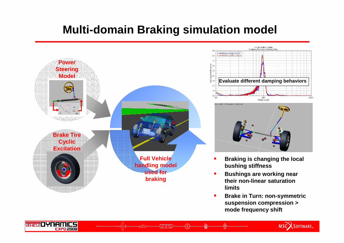
Multi-domain Braking simulation model
Brake Tire Cyclic
Excitation
Power Steering Model
Full Vehicle handling model
used for braking
� Braking is changing the local bushing stiffness
� Bushings are working near their non-linear saturation limits
� Brake in Turn: non-symmetric suspension compression > mode frequency shift
Evaluate different damping behaviors

Distributed and multiple data sources
Full Vehicle Model
CAD physical properties
Bushings properties
Structural Elements
FE Mesh
Tires properties
Electric and Hydraulic
components
Environment
(roads and driver)
Database
40 different
files

Example 2: Accurate NVH ModelExchange between FEA and Multi Body Simulation
MD NASTRAN MD ADAMS
Flexible Body Generation
Full vehicle model with flex bodies:
� Better handling simulations � Accurate vibration simulations� Modal stress recovery� Recover time and modal loads
Time&Modal loads

Exchange from Multi Body to FEA
MD NASTRAN MD ADAMS
NASTRAN Subsystem Generation
� ADAMS Subsystem Benefits in MD NASTRAN :� Accurate dynamic representation� Use DMIG for complex ADAMS components� Recover ADAMS DATA and linearization position

Accurate Noise and Vibration FE analysis
MD NASTRAN MD ADAMS
NASTRAN Format Subsystem Generation
� Accurate Modal Analysis :� NASTRAN suspension in phase with ADAMS model� ADAMS linearization in exact roll and compression
position

ADAMS –> NASTRAN Subsystem Exchange
PART CONM2
JOINT MPC
GEOMETRY MESH
ADAMS NASTRAN
FORCES
WHITE BOXBLACK BOX
FLEX BODY DMIG
PART DMIG
JOINT
INTERFACES GRID
ADAMS NASTRAN
FORCES
FLEX BODY
MPC
ADAMS TO NASTRAN ELEMENTS MAPPING

Example 2: Model and subsystems multiple versions
+
NVH Model
Multiple Body Versions
Multiple Mass Versions
Multiple Load Conditions
Multiple Suspension Versions
MBS Model

Simulation Life Cycle Management Challenges
� 4 Challenges� Maintain Product Context for CAE information� Make CAE information referable� Keep inter-relations of CAE information with other domains� Manage CAE information during the product lifecycle
Unique model configurations for each discipline
Unique model types for same geometry
Multiple simulations or “studies” for each geometry
Different configurations and variants of models for each simulation or study
Models and results associated with methods used to create them: CAE is “path dependent”
Methods are not associated with a particular geometry, configuration, or project
Many “standard” entities are required for simulation that have no geometric counterpart
Standards are not associated with a particular geometry, configuration, or project
Simulations are run to assess performance against targets or requirements
Every geometry has many discipline specific requirements

Simulation Audit ability and Traceability
� Each simulation object appears in project tree
� Objects are related to their parents and Childs
� Methods used to generate objects from others are controlled

Simulation Revisioning
� Review Simulation configurations� Instantiate new configurations� Compare configurations

Knowledge Capture and Reuse

Thank you for your attention !
Related Documents