-~- 0 -u-k_N_T-6-N-------i~ 5219 N. Shirley Street, Suite 100 Tacoma, Washington 98407 January 23, 2007 Mr. Kevin L. Rochlin Remedial Project Manager U.S. Environmental Protection Agency Region IO 1200 Sixth Avenue, ECL-111 Seattle, WA 98101 RE: Operation, Maintenance and Monitoring Plan On-Site Containment Facility Operable Unit No. 0206 Tacoma Smelter Site Dear Mr. Rochlin: Phone: 253.752.2185 Fax: 253.752.7083 RECEIVED JAN 2 5 2007 Environmental Cleanuo Office Point Ruston LLC is submitting the On-Site Containment Facility (OCF) Operation, Maintenance & Monitoring Plan for EPA review and approval pursuant to Section XI (EPA Approval of Plans and Other Submissions) of the Asarco Tacoma Smelter Consent Decree as specified in paragraph J of the Second Amendment to the Consent Decree. Two copies are enclosed. Please call me with any questions at 253-752-2185, ext. 240. Sincerely, Sue O'Neill cc: Chung Ki Yee - Washington Department of Ecology Doug Holsten - CH2MHill (2 copies) Leslie Ann Rose - Citizens for a Healthy Bay · USEPASF l!IWllll~il 1231909

Welcome message from author
This document is posted to help you gain knowledge. Please leave a comment to let me know what you think about it! Share it to your friends and learn new things together.
Transcript
-~-0-u-k_N_T-6-N-------i~ 5219 N. Shirley Street, Suite 100 Tacoma, Washington 98407
January 23, 2007
Mr. Kevin L. Rochlin Remedial Project Manager U.S. Environmental Protection Agency Region IO 1200 Sixth Avenue, ECL-111 Seattle, WA 98101
RE: Operation, Maintenance and Monitoring Plan On-Site Containment Facility Operable Unit No. 0206 Tacoma Smelter Site
Dear Mr. Rochlin:
Phone: 253.752.2185 Fax: 253.752.7083
RECEIVED
JAN 2 5 2007
Environmental Cleanuo Office
Point Ruston LLC is submitting the On-Site Containment Facility (OCF) Operation, Maintenance & Monitoring Plan for EPA review and approval pursuant to Section XI (EPA Approval of Plans and Other Submissions) of the Asarco Tacoma Smelter Consent Decree as specified in paragraph J of the Second Amendment to the Consent Decree. Two copies are enclosed.
Please call me with any questions at 253-752-2185, ext. 240.
Sincerely,
Sue O'Neill
cc: Chung Ki Yee - Washington Department of Ecology Doug Holsten - CH2MHill (2 copies) Leslie Ann Rose - Citizens for a Healthy Bay ·
~
USEPASF
l!IWllll~il 1231909
I I I
!I
I I I I I I I I I I I I I I I I
OPERATION, MAINTENANCE, AND MONITORING PLAN
TACOMA SMELTER ON-SITE CONTAINMENT FACILITY (OCF)
Operable Unit 02
Prepared for:
ASARCOLLC and
POINT RUSTON LLC Tacoma, WA
Prepared by:
Womack & Associates, Inc.
January 2007
RECEIVED
JAN 2 5 2007
Environmental Cleanup Office
I
I .I II :I
:1
ii .I
:1
II II
I II
I 11
I :1 I
.I
:1
:1
:1 :1
OCF-OMMP
TABLE OF CONTENTS
1.0 Introduction ................................................................................................................... 1
2.0 Post-RA Operations and Maintenance .......................................................................... 3
2.1 Operation and Maintenance Objectives ...................... , ............................................. 3
2.1.1 Leachate Collection and Leak Detection Systems ............................................. 4
2.1.2 Response Action Plan ........................................................................................ 9
2.1.3 Final Cover ....................................................................................................... 11
2.1.4 Bennett Street Parking Area ............................................................................. 15
2.1.5 Benchmarks ...................................................................................................... 15
2.1.6 Gas Monitoring .................... ; ........................................................................... 16
2.1. 7 Earthquake Damage ......................................................................................... 17
3.0 OCF Monitoring .......................................................................................................... 18
3.1 Groundwater Monitoring Program .............................. ; .......................................... 18
3.2 Groundwater Monitoring Locations and Wells ...................................................... 18
3.2.1 Groundwater Diversions and Controls ............................................................. 19
3.3 Groundwater Monitoring Parameters ..................................................................... 19
3.3.1 Groundwater Monitoring Frequency ............................................................... 20
3.3.2 Groundwater Sampling Methodology .............................................................. 20
4.0 Data Evaluation and Decision Process ....................................................................... 20
4.1 OCF Assessment ..................................................................................................... 20
5.0 Reporting and Schedule ............................................................ ; ................................. 22
6.0 References ................................................................................................................... 23
OCF-OMMP-January 2007.doc -11-
I I I I I I I I I I I I I I I I I I I
OCF-OMMP
LIST OF TABLES
TABLE 2-1. Maintenance/Inspection Schedule For The LCRS and LDCRS .......................... 8
TABLE 2-2. Maintenance/Inspection Schedule For OCF Final Cover ................................. .14
TABLE 2-3. Maintenance/Inspection Schedule For Benchmarks .......................................... 16
TABLE 2-4. Post-Earthquake Damage Inspection Requirements .......................................... 17.
FIGURE 1
FIGURE 2
FIGURE 3
FIGURE4
APPENDIX A APPENDIXB APPENDIXC APPENDIXD APPENDIXE
LIST OF FIGURES
OCF SITE PLAN - BENCHMARK LOCATIONS
BOTTOM LINER SYSTEM/LCRS AND LDCRS SUMP
LEACHATE COLLECTION SYSTEM PROFILE AND DETAILS
OCF COVER PERIMETER DRAIN SYSTEM, PLAN AND
DETAILS
LIST OF APPENDICES
40 CFR 264 Miscellaneous Sections Operation and Maintenance Manuals and Miscellaneous Information Contact Information OCF irrigation System Design Reporting Forms
OCF-OMMP-January 2007.doc -111-
I I
:_I
I I I I I I I I I I I I I I I I
OCF-OMMP
1.0 INTRODUCTION
This Operation, Maintenance, and Monitoring Plan (OMMP) describes the long-tem1
operation, maintenance, and monitoring activities to be conducted after completion of
remedial activities (RA) at the former Asarco Tacoma Smelter site (Site) On-Site
Containment Facility (OCF). The OMMP addresses operation, maintenance and monitoring
associated with the Tacoma Smelter Site OCF that is included in Operable Unit (OU) 02
(Asarco Tacoma Smelter - "Upland").
The final OCF cover was constructed during the fall of 2005. Asarco completed monitoring
of the OCF until the Site was purchased by Point Ruston in November of 2006. Point Ruston
assumed certain remaining obligations at the Site through execution of the Second
Amendment to the Consent Decree (October 2006). These obligations include continued
operation· and maintenance of the OCF as described in this OMMP.
This OCF OMMP has been prepared separately from the OMMP for the remainder of OU 02
(The Upland OMMP) since construction activities at the OCF have been completed prior to
completing RA in other areas within OU 02. The Upland OMMP addresses in detail the
monitoring requirements for groundwater and surface water, the process for data evaluation
and decisions, and reporting requirements that are applicable to the OCF OMMP. The OCF
OMMP refers to the Upland OMMP in these areas in order to provide consistency between
the two OMMPs. This OMMP should be used in conjunction with the Upland OMMP.
This OMMP is based on requirements described in the following documents:
• Record of Decision Commencement Bay Nearshore Tideflats Superfund Site
Operable Unit 02. Asarco Tacoma Smelter Facility Ruston and Tacoma,
Washington (March 1995).
• Final Statement of Work for the Commencement Bay Nearshore/Tideflats
Superfund Site Operable Unit 02 - Asarco Tacoma Smelter Facility and Peninsula
Remedial Design and Remedial Action (February 16, 1996).
OCF-OMMP-January 2007.doc -1-
I
I I -1
I I I I I
I I I I I I I I I I I ii
OCF-OMMP
• Surface Water Drainage and Control Remedial Design Report (Primary Activity
6.0). Attachment 6 to the Statement of Work (SOW) for the Commencement Bay
Nearshore/Tideflats Superfund Site Operable Unit 02. February 1996.
• Final Statement of Work for remedial Design and Remedial Action,
Commencement Bay Nearshore/Tideflats Superfund Site Operable Unit 2 and
Operable Unit 6, Exhibit F to the Second Amendment to the Consent Decree
(October 2006)
This OMMP is also based on input from the Asarco OMMP Task Force which convened
February through May 2001. This OMMP reflects the As-Built configuration of the OCF as
documented in the OCF as-built report (Womack & Associates, Inc., December 2005).
OCF-OMMP-January 2007.doc -2-
I I I
I I I I I I I I
:I
I I I I I I I I
OCF-OMMP
2.0 POST-RA OPERATIONS AND MAINTENANCE
The OCF will require O&M after RA to satisfy 40 CFR Sections 264.115-120 and 264.310.
The noted exception is that O&M for the OCF shall be indefinite rather than 30 years.
Requirements for a post-closure plan are outlined in 40 CFR Section 264.118. This OMMP
in conjunction with the Upland OMMP provides the post-closure plan for the OCF and the
other areas included in OU 02.
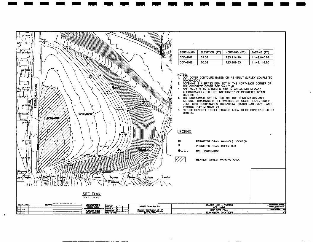
Figure 1 illustrates the as-built surface for the OCF cover and identifies locations for the
various components of the facility requiring monitoring and maintenance that are described
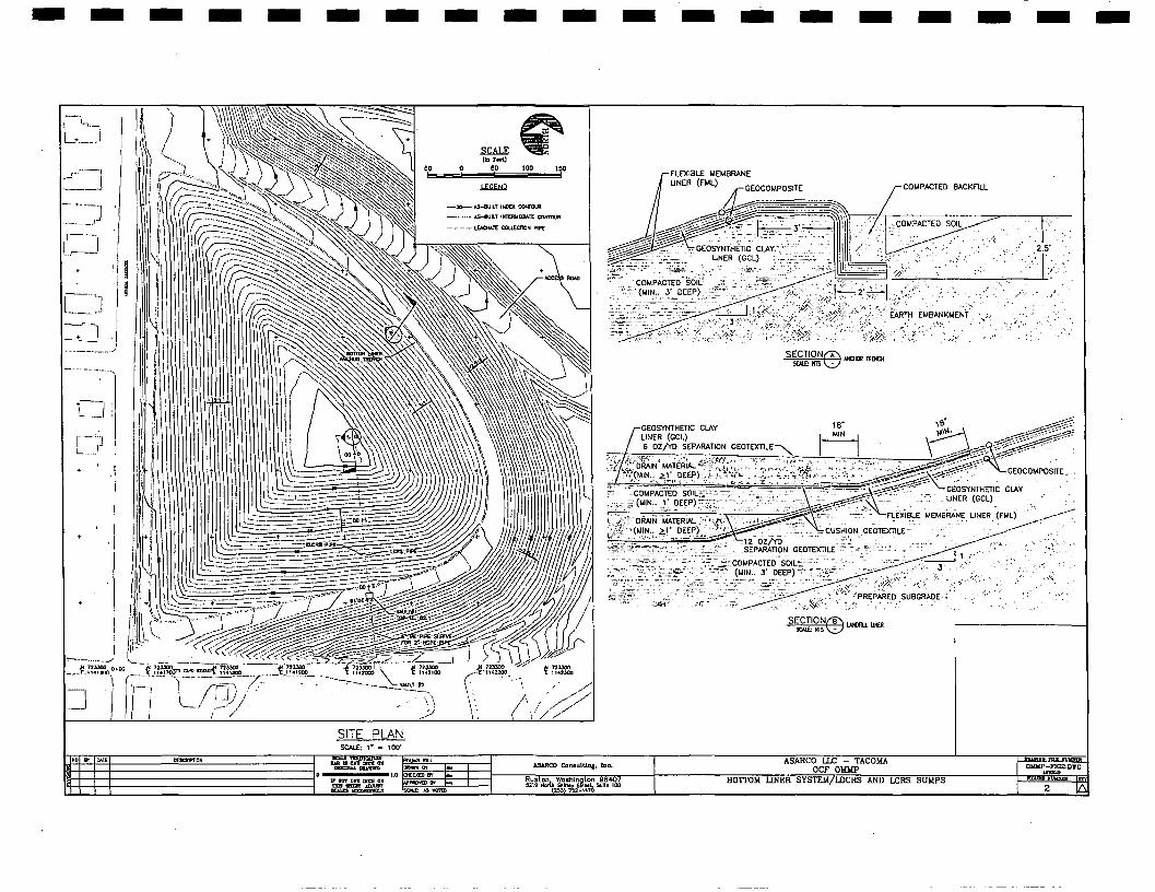
below. The OCF was constructed as a lined containment facility with a double composite
bottom liner system (see Figure 2) and a composite cover liner system. Detailed As-builts for
both the bottom and cover liner systems are presented in the OCF as-built report. Systems for
collection and removal of leachate and detection of leakage through the primary bottom
composite liner are incorporated in the OCF designs that are described in Section 2.1.1.
2.1 Operation and Maintenance Objectives
The ROD identifies standards from 40 CFR Part 264 that the OCF must comply with. Part
264 contains standards for owners and operators of hazardous waste treatment, storage, and
disposal facilities. Post-RA (post-closure) requirements are identified in Subpart G; Sections
264.115-120 and Subpart N; Section 264.310. Copies of the applicable sections from CFR 40
264 are attached in Appendix A. These sections require the following:
1) Provide a certification of closure (Sec. 264.115). Certification of closure will be
provided by Asarco, LLC and submitted to the regional administrator in
accordance with the requirements of this section;
2) Submit a survey plat (Sec. 264.116). The survey plat will be included with the
certification of closure;
3) Implement post-closure care including monitoring, maintenance, and reporting
(Sec. 264.117 and Sec. 264.31 O);
OCF-OMMP-January 2007.doc -3-
I I I I I I I II
I I I I I I I I I I I
OCF-OMMP
4) Submit a post-closure plan (Sec.264.118). Submittal of this OMMP fulfills this
requirement;
5) Submit post-closure notices (Sec. 264.119). Post closure notices will be submitted
within 60 days of certification of closure in accordance with the requirements of
this section; and
6) Submit certification of post-closure care (Sec. 264.120). Since the O&M period
for the OCF is indefinite a certification for the completion of post-closure care is
not applicable for the OCF. Annual reporting will therefore be used to document
the on-going operation, monitoring and maintenance activities for the OCF.
Specific O&M requirements as listed in Section 264.310 include:
I) Operate the leachate collection system. Refer to Section 2.1.1 below;
2) Maintain and monitor the leak detection system. Refer to Section 2.1.1 below;
3) Maintain the integrity and effectiveness of the final cover (settling, subsidence,
erosion, or other events). Refer to Section 2.1.3 below;
4) Prevent run-on and run-off from eroding the final cover. Refer to Section 2, 1.3
below;
5) Protect and maintain surveyed benchmarks used to comply with Sec. 264.309.
Refer to Section 2.1.5 below; and
6) Maintain a groundwater monitoring system. Refer to Section 3.1 below.
Due to the site location, an additional action is added that requires a thorough inspection after
a significant earthquake as described in Section 2.1. 7.
2.1.1 Leachate Collection and Leak Detection Systems
Liquid within the OCF can result from surface water allowed through the cover system along
with seepage resulting from precipitation contacting OCF backfill prior to constructing the
OCF cap. The leachate collection and removal system (LCRS) is the system between the
placed source area soils and the primary liner. It collects the liquid trapped on the primary
liner and pumps it to the leachate tank. The leak detection, collection and removal system
OCF-OMMP-January 2007.doc -4-
I I I I I
i I II
I I I I I I I I I I I I
OCF-OMMP
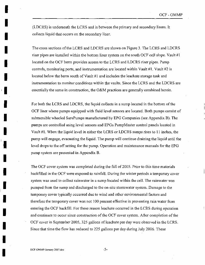
(LDCRS) is underneath the LCRS and is between the primary and secondary liners. It
collects liquid that occurs on the secondary liner.
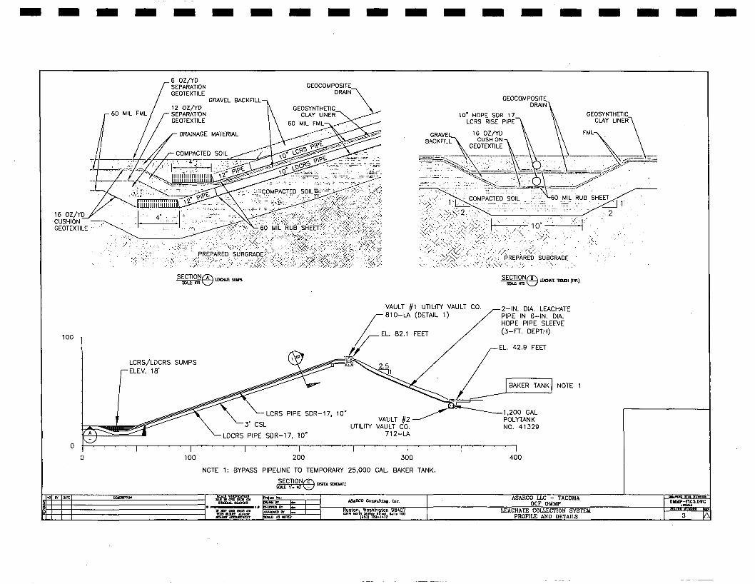
The cross sections of the LCRS and LDCRS are shown on Figure 3. The LCRS and LDCRS
riser pipes are installed within the bottom liner system on the south OCF cell slope. Vault #1
located on the OCF berm provides access to the LCRS and LDCRS riser pipes. Pump
controls, monitoring ports, and instrumentation are located within Vault #1. Vault #2 is
located below the berm south of Vault #1 and includes the leachate storage tank and
instrumentation to monitor conditions within the vaults. Since the LCRS and the LDCRS are
essentially the same in construction, the O&M practices are generally combined herein.
For both the LCRS and LDCRS, the liquid collects in a sump located in the bottom of the
OCF liner where pumps equipped with fluid level sensors are located. Both pumps consist of
submersible wheeled SurePumps manufactured by EPG Companies (see Appendix B). The
pumps are controlled using level sensors and EPGs PumpMaster control panels located in
Vault #1. When the liquid level in either the LCRS or LDCRS sumps rises to 11 inches, the
pump will engage, evacuating the liquid. The pump will continue draining the liquid until the
level drops to the off setting for the pump. Operation and maintenance manuals for the EPG
pump system are presented in Appendix B.
The OCF cover system was completed during the fall of 2005. Prior to this time materials
backfilled in the OCF were exposed to rainfall. During the winter periods a temporary cover
system was used to collect rainwater in a sump located within the cell. The rainwater was
pumped from the sump and discharged to the on-site stormwater system. Damage to the
temporary cover typically occurred due to wind and other environmental factors and
therefore the temporary cover was not I 00 percent effective in preventing rain water from
entering the OCF backfill. For these reason leachate occurred in the LCRS during operation
and continues to occur since construction of the OCF cover system. After completion of the
OCF cover in September 2005, 325 gallons ofleachate per day were observed in the LCRS.
Since that time the flow has reduced to 225 gallons per day during July 2006. These
OCF-OMMP-January 2007.doc -5-
I I I I I I
'I I I I I I I I I I I I I
OCF-OMMP
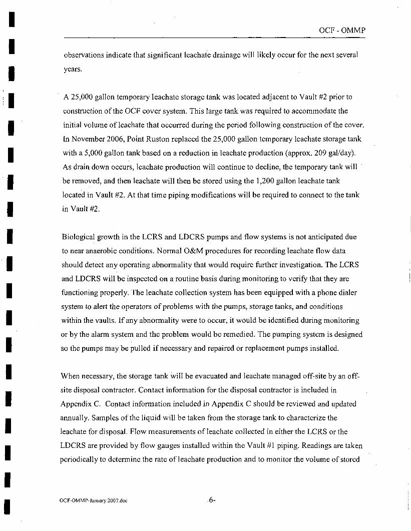
observations indicate that significant leachate drainage will likely occur for the next several
years.
A 25,000 gallon temporary leachate storage tank was located adjacent to Vault #2 prior to
construction of the OCF cover system. This large tank was required to accommodate the
initial volume ofleachate that occurred during the period following construction of the cover.
In November 2006, Point Ruston replaced the 25,000 gallon temporary leachate storage tank
with a 5,000 gallon tank based on a reduction in leachate production (approx. 209 gal/day).
As drain down occurs, leachate production will continue to decline, the temporary tank will
be removed, and then leachate will then be stored using the 1,200 gallon leachate tank
located in Vault #2. At that time piping modifications will be required to connect to the tank
in Vault #2.
Biological growth in the LCRS and LDCRS pumps and flow systems is not anticipated due
to near anaerobic conditions. Normal O&M procedures for recording leachate flow data
should detect any operating abnormality that would require further investigation. The LCRS
and LDCRS will be inspected on a routine basis during monitoring to verify that they are
functioning properly. The leachate collection system has been equipped with a phone dialer
system to alert the operators of problems with the pumps, storage tanks, and conditions
within the vaults. If any abnormality were to occur, it would be identified during monitoring
or by the alarm system and the problem would be remedied. The pumping system is designed
so the pumps may be pulled if necessary and repaired or replacement pumps installed.
When necessary, the storage tank will be evacuated and leachate managed off-site by an off
site disposal contractor. Contact information for the disposal contractor is included in
Appendix C. Contact information included in Appendix C should be reviewed and updated
annually. Samples of the liquid will be taken from the storage tank to characterize the
leachate for disposal. Flow measurements of leachate collected in either the LCRS or the
LDCRS are provided by flow gauges installed within the Vault #1 piping. Readings are taken
periodically to determine the rate of leachate production and to monitor the volume of stored
OCF-OMMP-January 2007.doc -6-
I I I I I I I I I I I I I I I I I I I
OCF-OMMP
leachate. Leachate volume within the storage tank is carefully monitored to allow scheduling
for removal by the off-site disposal contractor.
Monitoring ofleachate storage volumes and operation of the LCRS and LDCRS is provided
using a system of phone dialers located in Vault #I. The system includes two phone dialers
and six alarm settings. The phone dialers will be set to contact a security monitoring
contractor in the event of a pump malfunction, flooding in the vaults, or when the leachate
storage tank requires pumping once leachate is routed to the collection tank located in the
lower vault. In the event of an alarm, the monitoring contractor will contact oversight and
maintenance personnel who will assess the reason for the alarm, provide any required
maintenance, schedule the disposal contractor to pump the leachate storage tank, and reset
the pump controls and monitoring system. Contact information for the security monitoring
contractor, maintenance personnel and operator are also included in Appendix C and should
be reviewed and updated annually.
The first dialer monitors the operation of the pumps in the LCRS and LDCRS and sends an
alarm when the pumps fail to operate. Pump operation is controlled by level sensors installed
on the pumps. The pumps are designed to turn on in response to level sensors located in the
LCRS and LDCRS sumps. An alarm occurs when the pump does not respond to levels
exceeding the pump on level. Dialer 1 also monitors the leachate level in the storage tank
located in Vault #2. When the tank level reaches 75 percent full an alarm is sent. In the event
that the 75 percent full alarm does not receive a response, a second alarm is sent when the
tank level reaches 90 percent full. In order to prevent overfilling the leachate storage tank and
spilling in vault #2, the LCRS and LDCRS pumps will not operate when the storage tank
exceeds the 90 percent full level. Leachate must be evacuated from the storage tank before
the system will resume pumping.
Dialer 2 monitors for flood conditions in Vaults 1 and 2, and an alarm is sent when flooding
occurs in the bottom of either vault. The wiring schematic for the monitoring/dialer system is
presented in Appendix B.
OCF-OMMP-January 2007.doc -7-
- - - - - - - - - - - - - - - - - - -OCF-OMMP
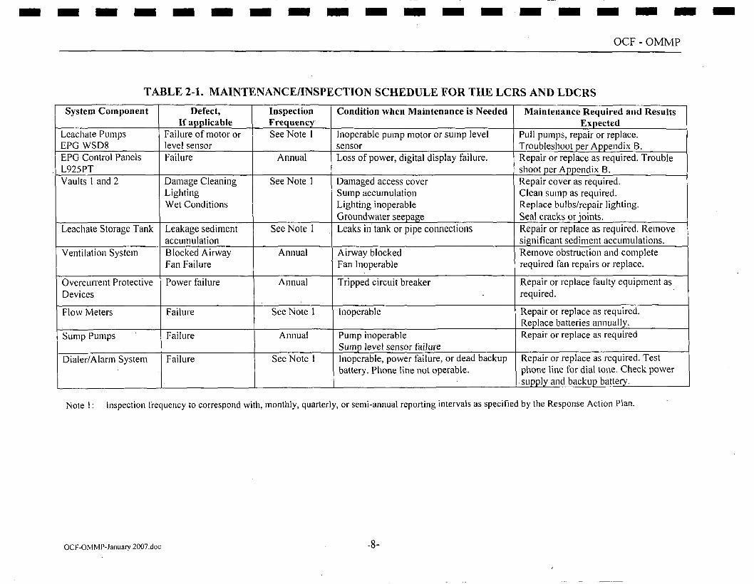
TABLE 2-1. MAINTENANCE/INSPECTION SCHEDULE FOR THE LCRS AND LDCRS
System Component Defect, Inspection Condition when Maintenance is Needed Maintenance Required and Results If applicable FreQuencv Expected
Leachate Pumps Failure of motor or See Note 1 Inoperable pump motor or sump level Pull pumps, repair or replace. EPG WSD8 level sensor sensor Troubleshoot per Appendix B. EPG Control Panels Failure Annual Loss of power, digital display failure. Repair or replace as required. Trouble L925PT shoot per Aooendix B. Vaults 1 and 2 Damage Cleaning See Note 1 Damaged access cover Repair cover as required.
Lighting Sump accumulation Clean sump as required. Wet Conditions Lighting inoperable Replace bulbs/repair lighting.
Groundwater seepage Seal cracks or ioints. Leachate Storage Tank Leakage sediment See Note 1 Leaks in tank or pipe connections Repair or replace as required. Remove
accumulation significant sediment accumulations. Yenti lation System Blocked Airway Annual Airway blocked Remove obstruction and complete
Fan Failure Fan Inoperable required fan repairs or replace.
Overcurrent Protective Power failure Annual Tripped circuit breaker Repair or replace faulty equipment as Devices required.
Flow Meters Failure See Note l Inoperable Repair or replace as required. Replace batteries annually.
Sump Pumps Failure Annual Pump inoperable Repair or replace as required Sump level sensor failure
Dialer/Alarm System Failure See Note l Inoperable, power failure, or dead backup Repair or replace as required. Test battery. Phone line not operable. phone line for dial tone. Check power
. supply and backup battery.
Note I: Inspection frequency to correspond with, monthly, quarterly, or semi-annual reporting intervals as specified by the Response Action Plan.
OCF-OMMP-January 20.07.doc -8-
I I I I I I I I I I I I I I I I I I I
OCF-OMMP
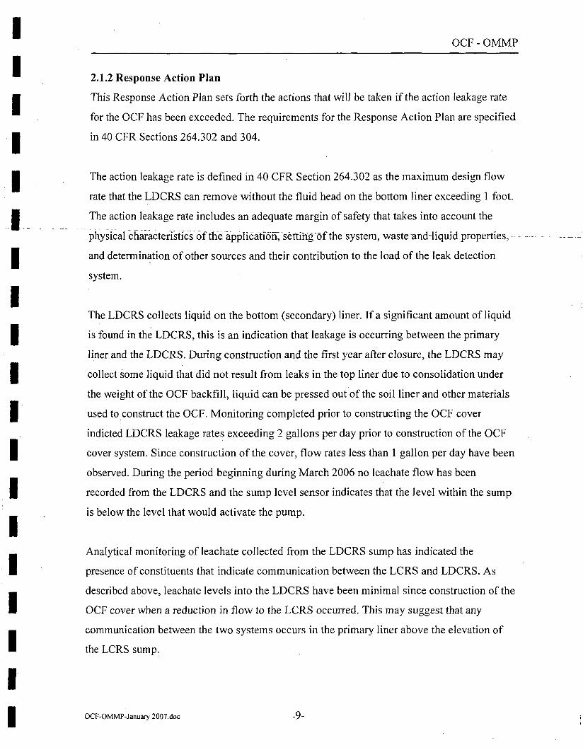
2.1.2 Response Action Plan
This Response Action Plan sets forth the actions that wiII be taken if the action leakage rate
for the OCF has been exceeded. The requirements for the Response Action Plan are specified
in 40 CFR Sections 264.302 and 304.
The action leakage rate is defined in 40 CFR Section 264.302 as the maximum design flow
rate that the LDCRS can remove without the fluid head on the bottom liner exceeding 1 foot.
The action leakage rate includes an adequate margin of safety that takes into account the
physical chai-actedstfcs of tffe applicatio~ settih~fof th-e system,-waste-and-liquid properties, - -
and determination of other sources and their contribution to the load of the leak detection
system.
The LDCRS collects liquid on the bottom (secondary) liner. If a significant amount of liquid
is found in the LDCRS, this is an indication that leakage is occurring between the primary
liner and the LDCRS. During construction and the first year after closure, the LDCRS may
collect some liquid that did not result from leaks in the top liner due to consolidation under
the weight of the OCF backfill, liquid can be pressed out of the soil liner and other materials
used to_construct the OCF. Monitoring completed prior to constructing the OCF cover
indicted LDC RS leakage rates exceeding 2 gallons per day prior to construction of the OCF
cover system. Since construction of the cover, flow rates less than 1 gallon per day have been
observed. During the period beginning during March 2006 no leachate flow has been
recorded from the LDCRS and the sump level sensor indicates that the level within the sump
is below the level that would activate the pump.
Analytical monitoring of leachate collected from the LDCRS sump has indicated the
presence of constituents that indicate communication between the LCRS and LDCRS. As
described above, leachate levels into the LDCRS have been minimal since construction of the
OCF cover when a reduction in flow to the LCRS occurred. This may suggest that any
communication between the two systems occurs in the primary liner above the elevation of
the LCRS sump.
OCF-OMMP-January 2007.doc -9-
I I I I I
. -1-----------
1 I I I I I I I I I
i I
I I
OCF-OMMP
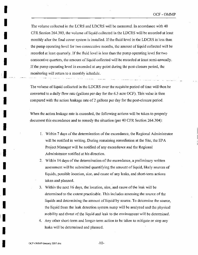
The volume collected in the LCRS and LDCRS will be measured. In accordance with 40
CFR Section 264.303, the volume of liquid collected in the LDCRS will be recorded at least
monthly after the final cover system is installed. If the fluid level in the LDCRS is less than
the pump operating level for two consecutive months, the amount of liquid collected will be
recorded at least quarterly. If the fluid level is less than the pump operating level for two
consecutive quarters, the amount of liquid collected will be recorded at least semi-annually.
If the pump operating level is exceeded at any point during the post-closure period, the
monitoring will return to a monthly schedule.
The volume of liquid collected in the LDCRS over the requisite period oftime will then be
converted to a daily flow rate (gallons per day for the 6.5 acre OCF). This value is then
compared with the action leakage rate of 2 gallons per day for the post-closure period.
When the action leakage rate is exceeded, the following actions will be taken to properly
document this exceedance and to remedy the situation (per 40 CFR Section 264.304):
I. Within 7 days of the determination of the exceedance, the Regional Administrator
will be notified in writing. During remaining remediation at the Site, the EPA
Project Manager will be notified of any exceedance and the Regional
Administrator notified at his direction.
2. Within 14 days of the detennination of the exceedance, a preliminary written
assessment will be submitted quantifying the amount of liquid, likely sources of
liquids, possible location, size, and cause of any leaks, and short-term actions
taken and planned.
3. Within the·next 16 days, the location, size, and cause of the leak will be
determined to the extent practicable. This includes assessing the source of the
liquids and determining the amount of liquid by source. To determine the source,
the liquid from the leak detection system sump will be analyzed and the physical
mobility and threat of the liquid and leak to the environment will be determined.
4. Any other short-term and longer-term action to be taken to mitigate or stop any
leaks will be detennined and planned.
OCF-OMMP-January 2007.doc -10-
I
I I I I
I I I I I I I
OCF-OMMP
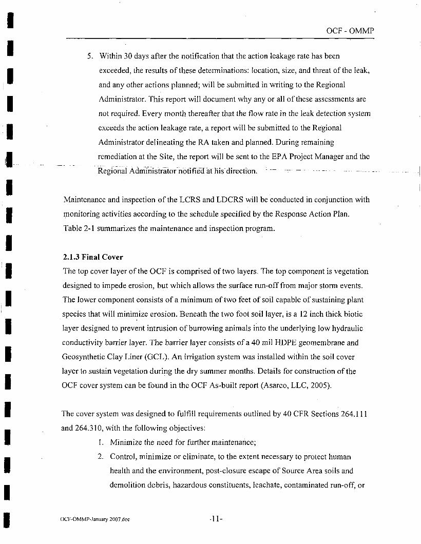
5. Within 30 days after the notification that the action leakage rate has been
exceeded, the results of these determinations: location, size, and threat of the leak,
and any other actions planned; will be submitted in writing to the Regional
Administrator. This report will document why any or all of these assessments are
not required. Every month thereafter that the flow rate in the leak detection system
exceeds the action leakage rate, a report will be submitted to the Regional
Administrator delineating the RA taken and planned. During remaining
remediation at the Site, the report will be sent to the EPA Project Manager and the
Maintenance and inspection of the LCRS and LDCRS will be conducted in conjunction with
monitoring activities according to the schedule specified by the Response Action Plan.
Table 2-1 summarizes the maintenance and inspection program.
2.1.3 Final Cover
The top cover layer of the OCF is comprised of two layers. The top component is vegetation
designed to impede erosion, but which allows the surface run-off from major storm events.
The lower component consists of a minimum of two feet of soil capable of sustaining plant
species that will minimize erosion. Beneath the two foot soil layer, is a 12 inch thick biotic . '
layer designed to prevent intrusion of burrowing animals into the underlying low hydraulic
conductivity barrier layer. The barrier layer consists of a 40 mil HDPE geomembrane and
Geosynthetic Clay Liner (GCL). An irrigation system was installed within the soil cover
layer to sustain vegetation during the dry summer months. Details for construction of the
OCF cover system can be found in the OCF As-built report (Asarco, LLC, 2005).
The cover system was designed to fulfill requirements outlined by 40 CFR Sections 264.111
and 264.310, with the following objectives:
I. Minimize the need for further maintenance;
2. Control, minimize or eliminate, to the extent necessary to protect human
health and the environment, post-closure escape of Source Area soils and
demolition debris, hazardous constituents, leachate, contaminated run-off, or
OCF-OMMP-January 2007.doc -11-
-- I
II I I I I
_I
I I I I I I I I I I I I I
OCF-OMMP
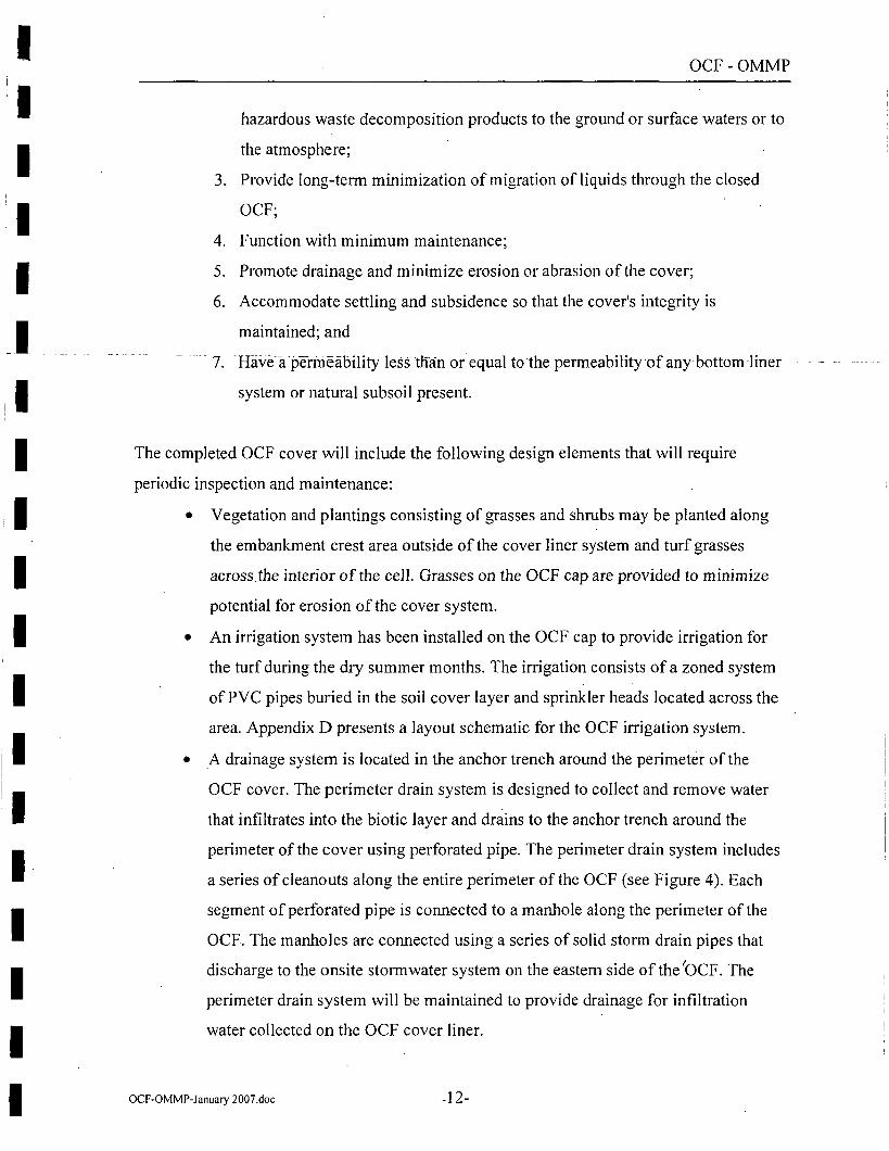
hazardous waste decomposition products to the ground or surface waters or to
the atmosphere;
3. Provide long-term minimization of migration of liquids through the closed
OCF;
4. Function with minimum maintenance;
5. Promote drainage and minimize erosion or abrasion of the cover;
6. Accommodate settling and subsidence so that the cover's integrity is
maintained; and
·- 7. ·Have~a-permeability less titan orequal to·the permeability-of any-bottom liner - -
system or natural subsoil present.
The completed OCF cover will include the following design elements that will require
periodic inspection and maintenance:
• Vegetation and plantings consisting of grasses and shrubs may be planted along
the embankment crest area outside of the cover liner system and turf grasses
across the interior of the cell. Grasses on the OCF cap are provided to minimize
potential for erosion of the cover system.
• An irrigation system has been installed on the OCF cap to provide irrigation for
the turf during the dry summer months. The irrigation consists of a zoned system
of PVC pipes buried in the soil cover layer and sprinkler heads located across the
area. Appendix D presents a layout schematic for the OCF irrigation system.
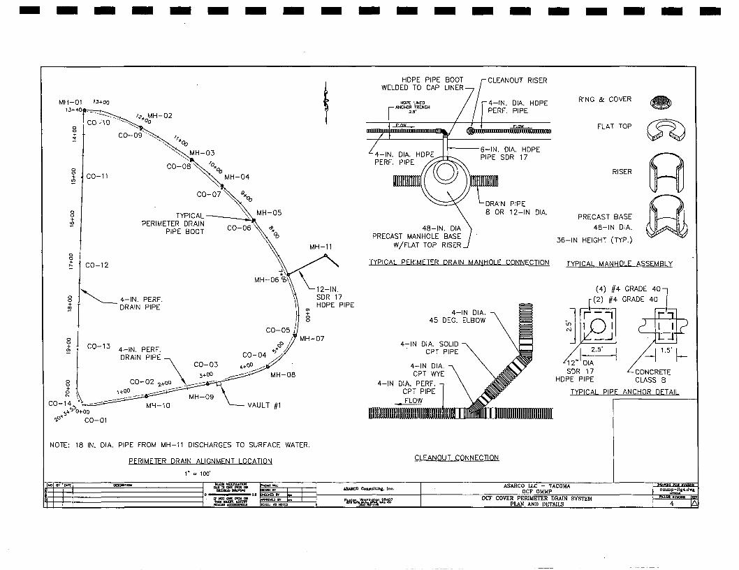
• A drainage system is located in the anchor trench around the perimeter of the
OCF cover. The perimeter drain system is designed to collect and remove water
that infiltrates into the biotic layer and drains to the anchor trench around the
perimeter of the cover using perforated pipe. The perimeter drain system includes
a series of cleanouts along the entire perimeter of the OCF (see Figure 4). Each
segment of perforated pipe is connected to a manhole along the perimeter of the
OCF. The manholes are connected using a series of solid storm drain pipes that
discharge to the onsite storm water system on the eastern side of the 'OCF. The
perimeter drain system will be maintained to provide drainage for infiltration
water collected on the OCF cover liner.
OCF-OMMP-January 2007.doc -12-
I I I I I
--1 I
I I
I I I I
'I I I I I I I
OCF-OMMP
• A drainage swale is located on the east side of Bennett Street adjacent to the
western edge of the OCF cover and north of the proposed Bennett Street parking
area. The swale will provide drainage of surface runoff that occurs from the slope
below the shoulder of Bennett Street and will divert surface water to the north.
Erosion along the swale may compromise the integrity of the cover system and
obstructions within the swale could prevent runoff and result in ponding.
Inspection and maintenance of the swale are required to prevent erosion, ponding,
and to promote runoff.
Additionally, consolidation of source area fill in the OCF cell may result in minor differential
settlement that may require maintenance of the cap components identified above. The
inspection and maintenance program for the final cover system is outlined in Table 2-2. This
program includes maintenance and inspection items for the proposed Bennett Street Parking
Area. Construction of the parking area has not been completed prior to finalizing this
OMMP. Therefore the maintenance items identified for the parking area will need to be
reviewed and updated upon completion of the construction. An addendum to the OMMP may
be required and should be submitted in the annual report following the completion of.
construction.
OCF-OMMP-January 2007.doc -13-
- - - - - - - - - - - - - - - - - - -OCF-OMMP
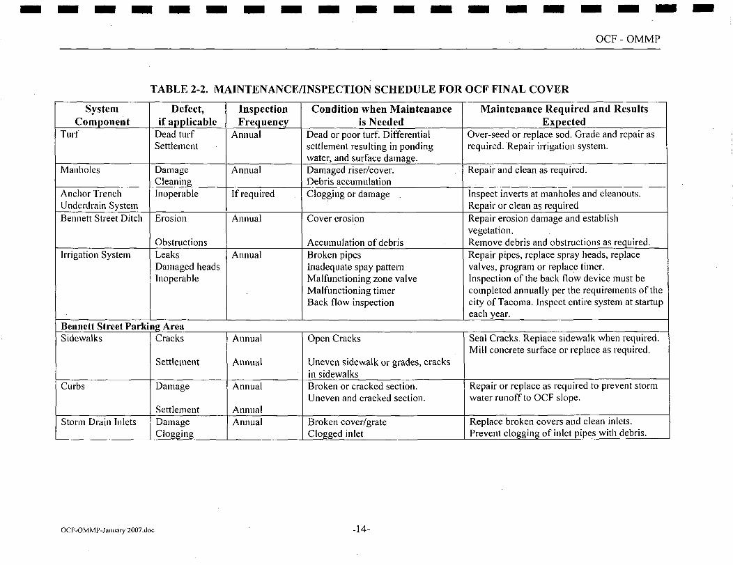
TABLE 2-2. MAINTENANCE/INSPECTION SCHEDULE FOR OCF FINAL COVER
System Defect, Inspection Condition when Maintenance Maintenance Required and Results Component if applicable Frequency is Needed Expected
Turf Dead turf Annual Dead or poor turf. Differential Over-seed or replace sod. Grade and repair as Settlement settlement resulting in ponding required. Repair irrigation system.
water, and surface damage. Manholes Damage Annual Damaged riser/cover. Repair and clean as required.
Cleaning Debris accumulation Anchor Trench Inoperable If required Clogging or damage Inspect inverts at manholes and cleanouts. Underdrain System Repair or clean as required Bennett Street Ditch Erosion Annual Cover erosion Repair erosion damage and establish
vegetation. Obstructions Accumulation of debris Remove debris and obstructions as required.
Irrigation System Leaks Annual Broken pipes Repair pipes, replace spray heads, replace Damaged heads Inadequate spay pattern valves, program or replac_e timer. Inoperable Malfunctioning zone valve Inspection of the back flow device must be
Malfunctioning timer completed annually per the requirements of the Back flow inspection city of Tacoma. Jnspect entire system at startup
each year. Bennett Street Parking Area Sidewalks Cracks Annual Open Cracks Seal Cracks. Replace sidewalk when required.
Mill concrete surface or replace as required. Settlement Annual Uneven sidewalk or grades, cracks
in sidewalks Curbs Damage Annual Broken or cracked section. Repair or replace as required to prevent storm
Uneven and cracked section. water runoff to OCF slope. Settlement Annual
Storm Drain Inlets Damage Annual Broken cover/grate Replace broken covers and clean inlets. Clogging Clogged inlet Prevent clogging of inlet pipes with debris.
OCF-OMMP-January 2007.doc -14-
I I I I I
_,_
I I I I I I I I I I I I I
OCF-OMMP
2.1.4 Bennett Street Parking Area
A parking area is proposed over the southwest comer of The OCF that will be maintained by
the Town of Ruston. The parking area is to be constructed with a storm water collection
system that will drain to the storm drain located on Bennett Street, west of the OCF. The
parking area will include curbing and drain inlets to collect stormwater runoff. The
pavement, storm inlets, and curbing should be maintained to prevent stormwater runoff from
the parking area onto the OCF. All stormwater resulting from the parking area should be
diverted to the Bennett Street storm sewer. The OCF perimeter drain system his not been
designed to accommodate runoff from the parking area.
A 3H: 1 V fill slope will occur around the north and eastern sides of the parking area. The fill
should be maintained to prevent erosion and damage to the fill and potential impacts to the
underlying OCF cover system and OCF embankment slope at the southern edge of the
parking area.
Use of the Bennett Street Parking area should not include any activities including
construction, excavation or other impacts that could potentially jeopardize the OCF cover
system. Boring, trenching or any other excavation that may penetrate the OCF cover liner
system is prohibited. Load bearing elements that could result in a point load being applied to
the OCF cover liner system should not be allowed. Conditions within the Bennett Street
Parking area should be monitored annually to identify maintenance requirements.
2.1.5 Benchmarks
Maintenance of benchmarks must comply with 40 CFR Section 264.309 which requires the
identification of the following:
• Permanently surveyed benchmarks on a map that also shows the exact location
and dimension, including depth, of the OCF; and
• The contents of the OCF and the approximate location of the waste within the
cell.
OCF-OMMP-January 2007.doc -15-
I
I I I I I I I
I I I I I I
OCF-OMMP
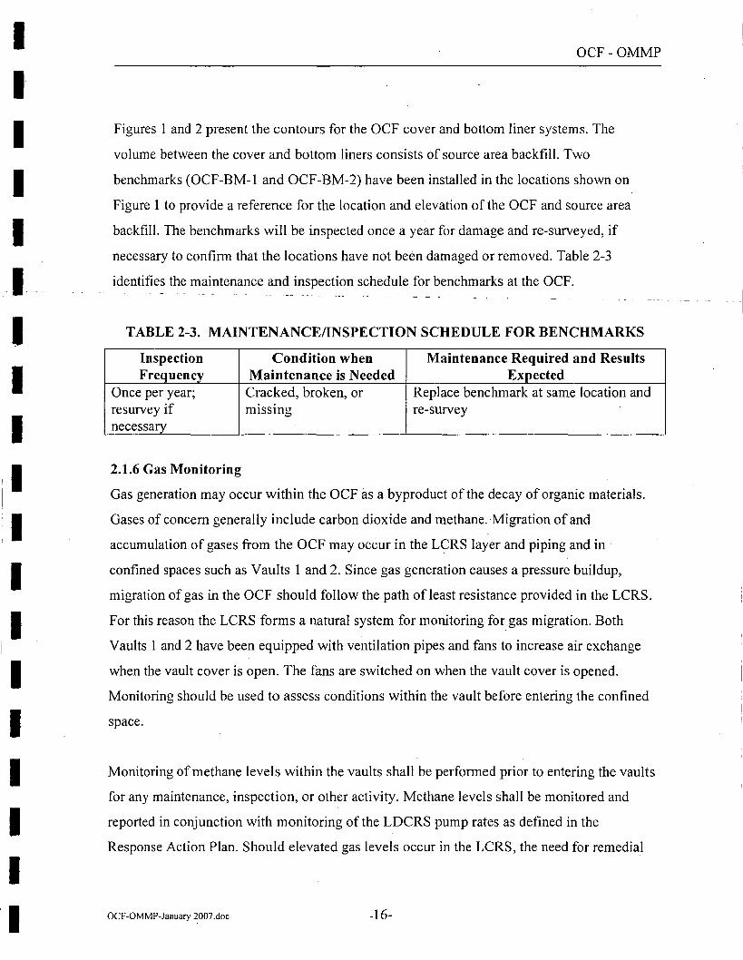
Figures 1 and 2 present the contours for the OCF cover and bottom liner systems. The
volume between the cover and bottom liners consists of source area backfill. Two
benchmarks (OCF-BM-1 and OCF-BM-2) have been installed in the locations shown on
Figure 1 to provide a reference for the location and elevation of the OCF and source area
backfill. The benchmarks will be inspected once a year for damage and re-surveyed, if
necessary to confirm that the locations have not been damaged or removed. Table 2-3
identifies the maintenance and inspection schedule for benchmarks at the OCF.
TABLE 2-3. MAINTENANCE/INSPECTION SCHEDULE FOR BENCHMARKS
Inspection Condition when Maintenance Required and Results Frequency Maintenance is Needed Expected
Once per year; Cracked, broken,or Replace benchmark at same location and resurvey if missing re-survey necessary
2.1.6 Gas Monitoring
Gas generation may occur within the OCF as a byproduct of the decay of organic materials.
Gases of concern generally include carbon dioxide and methane. ·Migration of and
accumulation of gases from the OCF may occur in the LCRS layer and piping and in
confined spaces such as Vaults 1 and 2. Since gas generation causes a pressure buildup,
migration of gas in the OCF should follow the path of least resistance provided in the LCRS.
For this reason the LCRS forms a natural system for monitoring for gas migration. Both
Vaults 1 and 2 have been equipped with ventilation pipes and fans to increase air exchange
when the vault cover is open. The fans are switched on when the vault cover is opened.
Monitoring should be used to assess conditions within the vault before entering the confined
space.
Monitoring of methane levels within the vaults shall be performed prior to entering the vaults
for any maintenance, inspection, or other activity. Methane levels shall be monitored and
reported in conjunction with monitoring of the LDCRS pump rates as defined in the
Response Action Plan. Should elevated gas levels occur in the LCRS, the need for remedial
OCF-OMMP-January 2007_doc -16-
- - -1
I I I
I I I I I I I I I I I I
OCF-OMMP
action will be addressed. The frequency and requirement for gas monitoring should be
reviewed based on measured levels.
2.1.7 Earthquake Damage
Should a significant seismic event occur in close proximity to the OCF, a post-earthquake
inspection will be completed to assess potential damage to the OCF embankment and cover
system. A two-tier inspection program will be used to allow for a rapid assessment of
earthquake damage. The first-tier will consist of a preliminary 1nspection that wiffoe -
followed up by a more detailed assessment and evaluation (second-tier). First-tier inspection
activities will be initiated within 48 hours of the seismic event. The need and schedule for
second-tier activities will be identified based on the results from the First-Tier inspection.
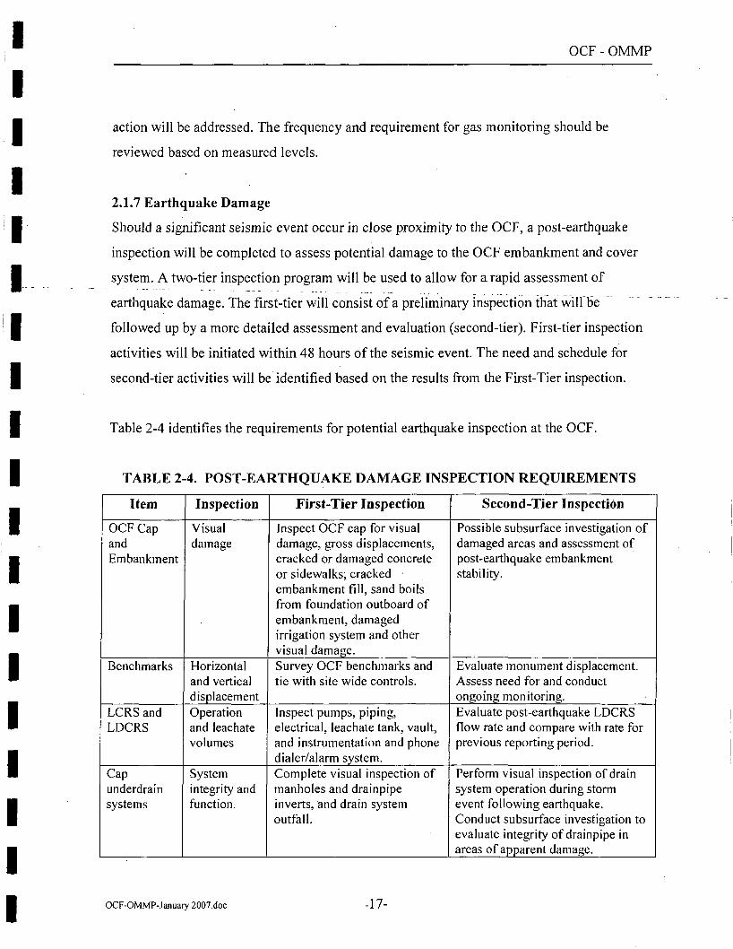
Table 2-4 identifies the requirements for potential earthquake inspection at the OCF.
TABLE 2-4. POST-EARTHQUAKE DAMAGE INSPECTION REQUIREMENTS
Item Inspection First-Tier Inspection Second-Tier Inspection
OCF Cap Visual Inspect OCF cap for visual Possible subsurface investigation of and damage damage, gross displacements, damaged areas and assessment of Embankment cracked or damaged concrete post-earthquake embankment
or sidewalks; cracked stability. embankment fill, sand boils from foundation outboard of embankment, damaged irrigation system and other visual damage.
Benchmarks Horizontal Survey OCF benchmarks and Evaluate monument displacement. and vertical tie with site wide controls. Assess need for and conduct displacement ongoing monitoring.
LCRS and Operation Inspect pumps, piping, Evaluate post-earthquake LDCRS LDCRS and leachate electrical, leachate tank, vault, flow rate and compare with rate for
volumes and instrumentation and phone previous reporting period. dialer/alarm system.
Cap System Complete visual inspection of Perform visual inspection of drain underdrain integrity and manholes and drainpipe system operation during storm systems function. inverts, and drain system event following earthquake.
outfall. Conduct subsurface investigation to evaluate integrity of drainpipe in areas of apparent damage.
OCF-OMMP-.lanuary 2007.doc -17-
I II
I I I
1_1 __
I I I I !I
I I :I I I I I I
OCF-OMMP
3.0 OCF MONITORING
Post-RA monitoring for OU 02 requires sample collection from groundwater monitoring
wells, surface water stations including outfalls, and marine water sample locations. In order
to prevent duplication of monitoring requirements and potential for discrepancies between
the OMMPs, monitoring requirements for the OCF are described in the Upland OMMP. This
section of the OCF OMMP provides a general discussion of the monitoring requirements
associated with the OCF.
The post-RA environmental monitoring program addresses objectives described in the OU 06
Statement of Work (USEPA 2001) as well as long-term monitoring requirements for OU 02.
As a result, the post-RA monitoring program primarily addresses groundwater, surface water
(including surface water runoff and marine water) and marine sediments.
The post-RA environmental monitoring program is intended to monitor environmental
conditions and trends after RA is complete. However, some monitoring activities will not
begin until completion of RA in the areas surrounding the OCF.
3.1 Groundwater Monitoring Program
Groundwater beneath the OCF generally flows in a northeasterly direction toward
Commencement Bay, the ultimate groundwater discharge point. Some shallow groundwater
discharges to the surface as seeps and springs in the upper elevations of the site, specifically
along the steeper slopes on the southwest side of the site.
3.2 Groundwater Monitoring Locations and Wells
The OCF groundwater monitoring well network is designed to meet the requirements of 40
CRF 264.90 through 264.99. The proposed OCF specific monitoring well network consists of
five new monitoring wells (OCF-1 through OCF-5) constructed outside the perimeter of the
OCF berm. OCF-5 is planned to replace the abandoned MW-140. This network will provide
upgradient and down-gradient monitoring data for the OCF. Once constructed, the locations
will be documented in the Upland OMMP.
OCF-OMMP-January 2007.doc -18-
I I I I I I I I I I I I I I I I I I I
OCF-OMMP
Groundwater monitoring wells will be installed in accordance with (WAC I 73-160) using the
same well construction procedures for monitoring wells constructed during the RI and during
RA to help ensure groundwater data comparability. A detailed description of procedures for
monitoring well installation and development is provided in the Upland OMMP.
3.2.1 Groundwater Diversions and Controls
Groundwater diversions and controls included in OU 02 discharge to the surface water
conveyance system and therefore will be monitored as part of the surface water monitoring
program. Groundwater diversions (subdrains) are installed in the OCF subgrade. Outflow
from the subdrain system may occur from the HDPE pipe to the surface drainage on the east
side of the OCF embankment. The location of this pipe is illustrated on Figure 1.
3.3 GROUNDWATER MONITORING PARAMETERS
As described in the OU 6 ROD, at a minimum, post-RA groundwater monitoring will include
measurement of the following:
• static groundwater level;
• general water quality parameters (temperature, pH, conductivity, salinity, total
dissolved solids, total suspended solids, turbidity (field) , dissolved oxygen,
chloride, and sulfate);
• metals (arsenic, cadmium, copper, iron, manganese, nickel, lead, zinc); and
organics.
Additional analytical requirements will be addressed in the Upland OMMP.
The primary purpose for groundwater monitoring down gradient of the OCF is to determine
if there are inc·reases in metal concentrations that may be indicative, when combined with
data from the OCF leachate collection and leak detection system, of potential leaks. As such,
only dissolved metals will be measured in the OCF groundwater monitoring wells. A
complete list of groundwater monitoring constituents for the OCF monitoring wells is
OCF-OMMP-January 2007.doc -19-
I I I I I I I I I I I I I-I I
I I I I I
OCF-OMMP
presented in the Upland OMMP. OCF groundwater data collected from wells OCF-1
through OCF-5 will be analyzed as described in Section 4.1.
3.3.1 Groundwater Monitoring Frequency
Refer to the Upland OMMP for the Post RA monitoring frequencies.
3.3.2 Groundwater Sampling Methodology
Groundwater sample collection methods will follow established procedures previously and
presently used on the Site for RA Site-wide monitoring. These procedures are outlined in the
Upland OMMP and include Standard Operating Procedures (SOPs), and field and analytical
protocols. Prior to implementation of the sampling programs, a post-RA monitoring Quality
Assurance Project Plan (QAPP) will be prepared. The post-RA Quality Assurance Project
Plan will be based on the RA Quality Assurance Project Plan.
4.0 DATA EVALUATION AND DECISION PROCESS
4.1 OCF Assessment
The primary indicator of containment of contaminants within the OCF is the operational
monitoring associated with the OCF liner leakage detection systems described in Section
2.1.1. Evaluation of OCF environmental monitoring data collected from down-gradient wells
(OCF 1 through 5) must be conducted in consideration of the results from monitoring the
liner leakage system, down-gradient monitoring wells, and an evaluation of down-gradient
trends. Since water quality down-gradient of the OCF has been previously impacted from
upland source areas (primarily the Copper Refinery area) evaluation of water quality against
groundwater standards (MCLs or others) is not appropriate. As a result, the key indicators of
a groundwater condition associated with the OCF that may require supplemental activities
are:
1. Water quality results from operational monitoring of the OCF leakage detection
systems that indicate leakage through one or more of the liners may have or is
occurring.
OCF-OMMP-January 2007.doc -20-
I I I I I I I I I I I I I I I I I I I
OCF-OMMP
2. Significant leachate production requiring pumping from the LCRS sump.
3. The occurrence of leachate in the LDCRS sump in quantities sufficient to activate
the LDCRS pump.
4. Increasing down-gradient groundwater trends coupled with conditions 1, 2 and 3.
If these conditions occur, the hydraulic head within the LCRS and LDCRS may have resulted
in leakage through the secondary bottom liner components. This occurrence could be
correlated with down-gradient groundwater trends. Likewise, if leachate does not occur in the
LCRS and LDCRS sumps it is not likely that contaminants to groundwater are associated
with the OCF. In either case the evaluation and decision process defined in the Upland
OMMP should be followed to identify conditions at which additional groundwater controls
would be considered. Likewise, surface water impacts resulting from the OCF should not
result in exceedances in effluent limits established to meet Class AA marine water quality
criteria at the edge of approved mixing zones at the completion of RA.
OCF-OMMP-January 2007.doc -21-
I I I I I I I I I I I ·1
I I I I I I I
OCF-OMMP
5.0 REPORTING AND SCHEDULE
The Upland OMMP includes a schedule of O&M activities for OU 02 and identifies specific
reporting requirements that include the OCF and the surrounding areas. Section 2 of this
OMMP provides a summary of the maintenance and inspection schedule for the various
components of the OCF.
Monitoring of the LCRS and LDCRS shall be completed according to the schedule required
by the Response Action Plan presented in Section 2.1.2. Monitoring for ground water and
surface water related to the OCF will be completed in accordance to the schedule defined in
the Upland OMMP. The maintenance and inspection of other OCF components including the
OCF cover, Bennett Street Parking Area, OCF Benchmarks shall be shall be completed on an
annual schedule. In the event of a significant seismic event the Phase I and Phase 2
inspection described in Section 2.1. 7 shall be completed. Maintenance and data collected for
each of these activities must be documented and reported in the appropriate OMMP
deliverables identified above and in the Upland OMMP.
Appendix E includes standard report forms to document inspection, and maintenance of the
OCF. The following forms are included:
• LCRS and LDCRS Inspection Report, and
• OCF Cover Inspection Report
Forms have been prepared to provide the inspector a checklist of items requiring inspection
and or maintenance. The forms should be reviewed and updated as appropriate to address
changing conditions at the OCF and to provide a record of conditions across the OCF. Report
forms should be maintained as part of the permanent record for the facility and should be
used during preparation of the various OMMP reports.
OCF-OMMP-January 2007.doc -22-
I
I I I I I I I I I I I I I I I I I
OCF-OMMP
6.0 REFERENCES
Hydrometries, Inc. 1999. On-Site Containment Facility (OCF) Final Design Analysis PA 1.0 - Group 1 b October 1999.
United States Environmental Protection Agency, 1995a. Record of Decision Commencement Bay Nearshore Tideflats Superfund Site Operable Unit 02. Asarco Tacoma Smelter Facility Ruston and Tacoma, Washington, March 1995.
United States Environmental Protection Agency, 1996b. Final Statement of Work for the Commencement Bay Nearshore/Tideflats Superfund Site Operable Unit 02 -Asarco Tacoma Smelter Facility and Peninsula Remedial Design and Remedial Action, February 16, 1996.
United States Environmental Protection Agency. 1990.
United States Environmental Protection Agency, 2000. Record of Decision Commencement Bay Nearshore Tideflats Superfund Site Operable Unit 06 Ruston and Tacoma, Washington, July 2000.
United States Environmental Protection Agency, 2001. Final Statement of Work for the Commencement Bay Nearshore Tideflats Superfund Site Operable Unit 06 Ruston and Tacoma, Washington, Draft, May 2001.
United States Environmental Protection Agency, 2006. Final Statement of Work for the Remedial Design and Remedial Action, Commencement Bay Nearshore/Tideflats Superfund Site Operable Unit 02 - Asarco Tacoma Smelter Facility and Peninsula and Operable Unit 06 - Marine Sediments and Groundwater, October 2006.
Womack & Associates, Inc., Asarco LLC - Tacoma OCF, As-Built Report, December, 2005.
OCF-OMMP-January 2007.doc -23-
I I I I I I I I I .
I FIGURES
I I I I I I I I I OCF-OMMP-January 2007.doc
- - - - - - - - - - -
/ , / /Jl,• _/~
-~~
~1-1~1~~,m~\ "' . ;:~·-, ~\l;:::\\~, SITE PLAN SCALE: 1 • • 100•
-
- - - - - -
BENCHMARK ELEVATION (FT) NORTHING (FT) EASTING (FT)
OCF-BM1 81.59 723,414.49 1,142,040.89
OCF-BM2 70.39 723,806.53 1, 142, 118.83
t:!,QIES;_ 1. OCF COVER CONTOURS BASED ON AS-BUILT SURVEY COMPLETED
1 0-31 -2005. 2. OCFBM-1 IS A BRASS DISK SET IN THE NOR'IHEAST CORNER OF
THE CONCRETE COVER FOR VAULT #1. 3. OCF BM-2 IS AN ALUMINUM CAP IN AN ALUMINUM CASE
APPROXIMATELY 8.6 FEET NORTHWEST OF PERIMETER DRAIN MANHOLE 5.
4. THE COORDINATE SYSTEM FOR THE OCF BENCHMARKS ANO AS-BUil T DRAWINGS IS THE WASHINGTON STA TE PLANE, SOUTH ZONE, GRID COORDINATES. HORIZONTAL DATUM NAO 83/91, AND VERTICAL DATUM NGVD 29.
5. FUTURE BENNETT STREET PARKING AREA TO BE CONSTRUCTED BY OTHERS.
LEGEND
PERIMETER DRAIN MANHOLE LOCATION
PERIMETER DRAIN CLEAN OUT
OCF BENCHMARK
BENNETT STREET PARKING AREA
ASARCO LLC - TACOMA OCF OIOIP
OCP' SITZ PLAN BENCHKARK LOCATIONS
- -
- - - - - - - - - - - - - - - - - - -~Q'
00 On :;at.) 100 1~0
- - -
100
0
0
- - -GRAVEL
MATERIAL
SECTIONED W0Wt 5'All'S SCll.[:1/15 -
LCRS/LDCRS SUMPS ELEV. 18'
- - -GEOCOMPOSITE
DRAIN
GEOSYNTHETIC
- - - -10" HOPE SOR 17
LCRS RISE
- -
S~l~(D WCll<TE TRD.X>l (llf.)
co. VAULT #1 UTILl1Y VAULT /, 810-LA (DETAIL 1) r EL. 82.1 FEET
2-IN. DIA. LEACHATE PIPE IN 6-IN. DIA. HDPE PIPE SLEEVE (3-FT. DEPTH)
/EL. 42.9 FEET r=-:=·
·~~ NOTE 1
LCRS PIPE SDR-17, 10"
3' CSL VAULT #2 ~
UTILl1Y VAULT CO.
1,200 GAL POLYTANK NO. 41329
LDCRS PIPE SDR-17, 10" 712-LA
100 200 300
NOTE 1: BYPASS PIPELINE TO TEMPORARY 25,000 GAL. BAKER TANK.
~c,:~~(D = sooonc
AS.t.RCD Comu!Una, Ina,
400
ASARCO LLC - TACOMA OCF OMMP
LEACHATE COLLECTION SYSTEM PROFILE AND DETAILS
- - - -
3
- - -MH-01 7J+oo
13+40
g + ...
g + "'
a 0 + "
C0-11
C0-12
-
8 ~ 4-IN. PERF. .;!; DRAIN PIPE
- - - -
NOTE: 18 IN. DIA. PIPE FROM MH-11 DISCHARGES TO SURFACE WATER.
PERIMETER DRAIN AUGNMENT LOCATION
1· ~ 100·
UlftlTOAIJtalOlf Tm3 mm,", ADMIT ~--..
-
MH-11
- -HOPE LINED
ANCHOR TRENCH 2.5'
-
48-IN. DIA PRECAST MANHOLE BASE
W/FLAT TOP RISER
- -4-IN. DIA. HOPE PERF. PIPE
PIPE 12-IN DIA.
- - -RING & COVER
FLAT TOP
RISER
PRECAST BASE
48-IN DIA.
36-IN HEIGHT (TYP.)
-
TYPICAL PERIMETER DRAIN MANHOLE CONNECTION TYPICAL MANHOLE ASSEMBLY
4-IN
.lSARCO Coa:11ulUnQ:, lna.
4-IN DIA. 45 DEG. ELBOW
4-IN DIA. SOLID CPT PIPE
CLEANOUT CONNECTION
(4) #4 GRADE 40
(2) #4 GRADE 40
r-7 I I
_ _J
2.5'
12"1 DIA SOR 17
HOPE PIPE
-I 1.s·~
CONCRETE CLASS B
TYPICAL PIPE ANCHOR DETAIL
ASARCO LLC - TACOMA OCF OMMP
OCF COVER PERIMETER DRAIN SYSTEM PLAN AND DETAILS
-
I I I I I I I I I
APPENDIX A
I 40 CFR Part 264 Miscellaneous Sections
I I I I I I I I I OCF-OMMP-January 2007.doc
I I I I I I I I I I I I I I I I I I I
Environmental Protection Agency
during the year to reduce the volume and toxicity of waste generated.
(i) For generators who treat, store, or dispose of hazardous waste on-site, a description of the changes in volume and toxicity of waste actually achieved during the year in comparison to previous years to the extent such information is available for the years prior to 1984.
U) The certification signed by the owner or operator of the facility or his authorized representative.
[45 FR 33221, May 19, 1980, as amended at 46 FR 2849. Jan. 12, 1981: 48 FR 3982. Jan. 28. 1983; 50 FR 4514, Jan. 31, 1985; 51 FR 28556, Aug. 8, 19861
§ 264.76 Unmanifested waste report. If a facility accepts for treatment,
storage. or disposal any hazardous waste from an off-site source without an accompanying rnanifest, or without an accompanying shipping paper as described in § 263.20(e)(2) of this chapter, and if the waste is not excluded from the manifest requirement by § 261.5 of this chapter, then the owner or operator must prepare and submit a single copy of a report to the Regional Administrator within fifteen days after receiving the waste. The unmanifested waste report must be submitted on EPA form 8700-138. Such report must be designated 'Unmanifested Waste Report' and include the following information:
(a) The EPA identification number, name, and address of the facility;
(b) The date the facility received the waste:
(c) The EPA identification number, name, and address of the generator and the transporter, if available:
(d) A description and the quantity of each unmanifested hazardous waste and facility received;
(e) The method of treatment, storage, or disposal for each hazardous waste;
(f) The certification signed by the owner or operator of the facility or his authorized representative: and
(g) A brief explanation of why the waste was unmanifested, if known.
[ Comment: Small quantities of hazardous waste are excluded from regulation under this part and do not require a manifest. Where a facility receives unmanifested hazardous wastes. the Agency suggests that the
§264.90
owner or operator obtain from each generator a certification that the waste qualifies for exclusion. Otherwise, the Agency suggests that the owner or operator file an unmanlfested waste report for the hazardous waste movement.]
(45 FR 33221, May 19, 1980, as amended at 48 FR 3982. Jan. 28, 1983; 50 FR 4514, Jan. 31, 1985]
§ 264.77 Additional reports.
In addition to submitting the biennial reports and unmanifested waste reports described in §§264.75 and 264.76, the owner or operator must also report to the Regional Administrator:
(a) Releases. fires, and explosions as specified in§ 264.56(j);
(b) Facility closures specified in §264.115: and
(c) As otherwise required by subparts F, K through N. AA, BB, and CC of this part.
[46 FR 2849, Jan. 12, 1981, as amended at 47 FR 32350, July 26, 1982; 48 FR 3982, Jan. 28, 1983; 55 FR 25494. June 21. 1990; 59 FR 62926. Dec. 6. 1994]
Subpart F-Releases From Solid Waste Management Units
SOURCE: 47 FR 32350, July 26. 1982, unless otherwise noted.
§ 264.90 Applicability.
(a)(!) Except as provided in paragraph (b) of this section, the regulations in this subpart apply to owners or operators of facilities that treat, store or dispose of hazardous waste. The owner or operator must satisfy the requirements identified in paragraph (a)(2) of this section for all wastes (or constituents thereof) contained in solid waste management units at the facility, regardless of the time at which waste was placed in such units.
(2) All solid waste management units must comply with the requirements in §264.101. A surface impoundment, waste pile, and land treatment unit or landfill that receives hazardous waste after July 26, 1982 (hereinafter referred to as a "regulated unit") must comply with the requirements of §§ 264.91 through 264.100 in lieu of§ 264.101 for purposes of
183
I I I I I I I I I I I I I I I I I I I
§264.90
detecting, characterizing and responding to releases to the uppermost aquifer. The financial responsibility requirements of § 264. 101 apply to regulated units.
(b) The owner or operator's regulated unit or units are not subject to regulation for releases into the uppermost aquifer under this subpart if:
(1) The owner or operator is exempted under §264.1; or
(2) He operates a unit which the Regional Administrator finds:
(i) Is an engineered structure, (ii) Does not receive or contain liquid
waste or waste containing free liquids. (iii) Is designed and operated to ex
clude liquid, precipitation, and other run-on and run-off,
(iv) Has both inner and outer layers of containment enclosing the waste,
(v) Has a leak detection system built into each containment layer,
(vi) The owner or operator will provide continuing operation and maintenance of these leak detection systems during the active life of the unit and the closure and post-closure care periods, and
(vii) To a reasonable degree of certainty, will not allow hazardous constituents to migrate beyond the outer
· containment layer prior to the end of the post-closure care period.
(3) The Regional Administrator finds, pursuant to §264.280(d), that the treatment zone of a land treatment unit that qualifies as a regulated unit does not contain levels of hazardous constituents that are above background levels of those constituents by an amount that is statistically significant. and if an unsaturated zone monitoring program meeting the requirements of §264.278 has not shown a statistically significant increase in hazardous constituents below the treatment zone during the operating life of the unit. An exemption under this paragraph can only relieve an owner or operator of responsibility to meet the requirements of this subpart during the post-closure care period; or
(4) The Regional Administrator finds that there is no potential for migration of liquid from a regulated unit to the uppermost aquifer during the active life of the regulated unit (including the closure period) and the post-closure
40 CFR Ch. I (7-1-99 Edition)
care period specified under §264.117. This demonstration must be certified by a qualified geologist or geotechnical engineer. In order to provide an adequate margin of safety in the prediction of potential migration of liquid, the owner or operator must base any predictions made under this paragraph on assumptions that maximize the rate of liquid migration.
(5) He designs and operates a pile in compliance with §264.250(c).
(c) The regulations under this subpart apply during the active life of the regulated unit (including the closure period). After closure of the regulated unit, the regulations in this subpart:
(1) Do not apply if all waste, waste residues, contaminated containment system components, and contaminated subsoils are removed or decontaminated at closure:
(2) Apply during the post-closure care period under §264.117 if the owner or operator is conducting a detection monitoring program under§ 264.98; or
(3) Apply during the compliance period under §264.96 if the owner or operator is conducting a compliance monitoring program under § 264.99 or a corrective action program under §264.100.
(d) Regulations in this subpart may apply to miscellaneous units when necessary to comply with §§264.601 through 264.603.
(e) The regulations of this subpart apply to all owners and operators subject to the requirements of 40 CFR 270.1 (c)(7). when the Agency issues either a post-closure permit or an enforceable document (as defined in 40 CFR 270.l(c)(7)) at the facility. When the Agency issues an enforceable document, references in this subpart to "in the permit" mean "in the enforceable document."
(f) The Regional Administrator may replace all or part of the requirements of§§264.91 through 264.100 applying to a regulated unit with alternative requirements for groundwater monitoring and corrective action for releases to groundwater set out in the permit (or in an enforceable document) (as defined in 40 CFR 270.1 (c)(7)) where the Regional Administrator determines that:
(I) The regulated unit is situated among solid waste management units
184
,I I I I I I I I I I I I I I I I I I I
Environmental Protection Agency
(or areas of concern), a release has occurred. and both the regulated unit and one or more solid waste management unit(s) (or areas of concern) are likely to have contributed to the release; and
(2) It is not necessary to apply the groundwater monitoring and corrective action requirements of§§ 264.91 through 264. 100 because alternative requirements will protect human health and the environment.
[47 FR 32350. July 26, 1982, as amended at 50 FR 28746, July 15, 1985; 52 FR 46963, Dec. 10. 1987; 63 FR 56733. Oct. 22. 1998]
§ 264.91 Required programs. (a) Owners and operators subject to
this subpart must conduct a monitoring and response program as follows:
(I) Whenever hazardous constituents under §264.93 from a regulated unit are detected at a compliance point under § 264.95, the owner or operator must institute a compliance monitoring program under §264.99. Detected is defined as statistically significant evidence of contamination as described in §264.98(f);
(2) Whenever the ground-water protection standard under §264.92 is exceeded, the owner or operator must institute a corrective action program under § 264.100. Exceeded is defined as statistically significant evidence of increased contamination as described in § 264.99(d);
(3) Whenever hazardous constituents under §264.93 from a regulated unit exceed concentration limits under §264.94 in ground water between the compliance point under § 264.95 and the downgradient facility property boundary. the owner or operator must institute a corrective action program under §264.100; or
(4) In all other cases. the owner or operator must institute a detection monitoring program under§ 264.98.
(b) The Regional Administrator will specify in the facility permit the specific elements of the monitoring and response program. The Regional Administrator may include one or more of the programs identified in paragraph (a) of this section in the facility permit as may be necessary to protect human health and the environment and will specify the circumstances under which
§264.93
each of the programs will be required. In deciding whether to require the owner or operator to be prepared to institute a particular program, the Regional Administrator will consider the potential adverse effects on human health and the environment that might occur before final administrative action on a permit modification application to incorporate such a program could be taken.
[47 FR 32350, July 26, 1982, as amended at 53 FR 39728, Oct. 11, 1988]
, § 264.92 Ground-water standard.
protection
The owner or operator must comply with conditions specified in the facility permit that are designed to ensure that hazardous constituents under § 264.93 detected in the ground water from a regulated unit do not exceed the concentration limits under § 264.94 in the uppermost aquifer underlying the waste management area beyond the point of compliance under § 264.95 during the compliance period under §264.96 .. The Regional Administrator will establish this ground-water protection standard in the facility permit when hazardous constituents have been detected in the ground water.
[53 FR 39728, Oct. 11. 19881
§ 264.93 Hazardous constituents.
(a) The Regional Administrator will specify in the facility permit the hazardous constituents to which the. ground-water protection standard of §264.92 applies. Hazardous constituents are constituents identified in appendix VIII of part 261 of this chapter that have been detected in ground water in the uppermost aquifer underlying a regulated unit and that are reasonably expected to be in or derived from waste contained in a regulated unit. unless the Regional Administrator has excluded them under paragraph (b) of this section.
(b) The Regional Administrator will exclude an appendix VIII constituent from the list of hazardous constituents specified in the facility permit if he finds that the constituent is not capable of posing a substantial present or potential hazard to human health or the environment. In deciding whether
185
I I I I I I I I I I I I I I I I I I I
§ 264.94
to grant an exemption, the Regional Administrator will consider the following:
{I) Potential adverse effects on ground-water quality, considering:
(i) The physical and chemical characteristics of the waste in the regulated unit, including its potential for migration;
(ii) The hydrogeological characteristics of the facility and surrounding land;
(iii) The quantity of ground water and the direction of ground-water flow;
(iv) The proximity and withdrawal rates of ground-water users:
(v) The current and future uses of ground water in the area;
(vi) The existing quality of ground water. including other sources of contamination and their cumulative impact on the ground-water quality:
(vii) The potential for health risks caused by human exposure to waste constituents;
(viii) The potential damage to wildlife, crops, vegetation, and physical structures caused by exposure to waste constituents;
(ix) The persistence and permanence of the potential adverse effects: and
(2) Potential adverse effects on hydraulically-connected surface water quality, considering:
(i) The volume and physical and chemical characteristics of the waste in the regulated unit;
(ii) The hydrogeological characteristics of the facility and surrounding land;
(iii) The quantity and quality of ground water, and the direction of ground-water flow;
(iv) The patterns of rainfall in the region:
(v) The proximity of the regulated unit to surface waters:
(vi) The current and future uses of surface waters in the area and any water quality standards established for those surface waters:
(vii) The existing quality of surface water, including other sources of contamination and the cumulative impact on surface-water quality;
(viii) The potential for health risks caused by human exposure to waste constituents;
40 CFR Ch. I (7-1-99 Edition)
(ix) The potential damage to wildlife, crops, vegetation, and physical structures caused by exposure to waste constituents: and
(x) The persistence and permanence of the potential adverse effects.
(c) In making any determination under paragraph (b) of this section about the use of ground water in the area around the facility, the Regional Administrator will consider any identification of underground sources of drinking water and exempted aquifers made under§ 144.8 of this chapter.
[47 FR 32350, July 26, 1982, as amended at 48 FR 14294, Apr. I. 1983]
§ 264.94 Concentration limits.
(a) The Regional Administrator will specify in the facility permit concentration limits in the ground water for hazardous constituents established under § 264.93. The concentration of a hazardous constituent:
(I) Must not exceed the background level of that constituent in the ground water at the time that limit is specified in the permit: or
(2) For any of the constituents listed in Table I, must not exceed the respective value given in that table if the background level of the constituent is below the value given in Table I; or
TABLE 1-MAXIMUM CONCENTRATION OF CON-STITUENTS FOR GROUND-WATER PROTECTION
Constituent
Arsenic ..................................................................... .
Maximum con-
centration 1
0.05 Barium .............................................................. 1.0 Cadmium .................................... ........................ ....... 0.01 Chromium ............................... .............................. 0.05 Lead ..................................... ..................................... 0.05 Mercury ............................ .. ....................................... 0.002 Selenium ............................................. ...................... 0.01 Silver .......................................................................... 0.05 Endrin (1,2,3,4, 10, 10-hexachloro•1,7 •epoxy•
1,4,4a,S.6, 7,8.9a·octahydro-1, 4•endo. endo-5.8-dimethano naphthalene) ........................................ 0.0002
Lindane (1.2,3,4 ,S,6•hexachlorocyclohexane, gamma isomer) .............. ....................................... 0.004
Methoxychlor (1. 1. 1 •Trichloro-2.2-bis (p-methoxyphenylethane) ........................................... 0.1
Toxaphene (C,oH,0CI,. Technical chlorinated camphene. 67..;;,9 percent chlorine) 0.005
2,4-D (2,4•Dichlorophenoxyacetic acid) . 0.1 2,4.5-TP Silvex (2.4,5-Trichlorophenoxypropionic
acid) ..... .. ........................................ ..................... 0.01
1 Milligrams per liter.
186
I I I I I I I I I I I I I I I I I I I
Environmental Protection Agency
(3) Must not exceed an alternate limit established by the Regional Administrator under paragraph (b) of this section.
(b) The Regional Administrator will establish an alternate concentration limit for a hazardous constituent if he finds that the constituent will not pose a substantial present or potential hazard to human health or the environment as long as the alternate concentration limit is not exceeded. In establishing alternate concentration limits. the Regional Administrator will consider the following factors:
(I) Potential adverse effects on ground-water quality, considering:
(i) The physical and chemical characteristics of the waste in the regulated unit, including its potential for migration;
(ii) The hydrogeological characteristics of the facility and surrounding land;
{iii) The quantity of ground water and the direction of ground-water flow;
(iv) The proximity and withdrawal rates of ground-water users;
(v) The current and future uses of ground water in the area;
(vi) The existing quality of ground water, including other sources of contamination and their cumulative impact on the ground-water quality;
(vii) The potential for health risks caused by human exposure to waste constituents;
(viii) The potential damage to wildlife, crops. vegetation, and physical structures caused by exposure to waste constituents;
(ix) The persistence and permanence of the potential adverse effects; and
(2) Potential adverse effects on hy-draulically-connected surface-water quality, considering:
(i) The volume and physical and chemical characteristics of the waste in the regulated unit;
(ii) The hydrogeological characteristics of the facility and surrounding land;
(iii) The quantity and quality of ground water, and the direction of ground-water flow;
(iv) The patterns of rainfall in the region;
(v) The proximity of the regulated unit to surface waters;
§264.95
(vi) The current and future uses of surface waters in the area and any water quality standards established for those surface waters;
(vii) The existing quality of surface water, including other sources of contamination and the cumulative impact on surface water quality;
(viii) The potential for health risks caused by human exposure to waste constituents;
(ix) The potential damage to wildlife, crops. vegetation, and physical structures caused by exposure to waste constituents; and
(x) The persistence and permanence of the potential adverse effects.
(c) In making any determination under paragraph (b) of this section about the use of ground water in the area around the facility the Regional Administrator will consider any identification of underground sources of drinking water and exempted aquifers made under§ 144.8 of this chapter.
[47 FR 32350, July 26, 1982, as amended at 48 FR 14294, Apr. I, 1983)
§ 264.95 Point of compliance.
(a) The Regional Administrator will specify in the facility permit the point of compliance at which the groundwater protection standard of§ 264.92 applies and at which monitoring must be conducted. The point of compliance is a vertical surface located at the hydraulically downgradient limit of the waste management area that extends down into the uppermost aquifer underlying the regulated units.
(b) The waste management area is the limit projected in the horizontal plane of the area on which waste will be placed during the active life of a regulated unit.
(I) The waste management area includes horizontal space taken up by any liner, dike, or other barrier designed to contain waste in a regulated unit.
(2) If the facility contains more than one regulated unit, the waste management area is described by an imaginary line circumscribing the several regulated units.
187
I I I I I I I I I I I I I I I I I I I
§264.96
§ 264.96 Compliance period.
(a) The Regional Administrator will specify in the facility permit the compliance period during which the ground-water protection standard of § 264.92 applies. The compliance period is the number of years equal to the active life of the waste management area (including any waste management activity prior to permitting. and the closure period.)
(b) The compliance period begins when the owner or operator initiates a compliance monitoring program meeting the requirements of §264.99.
(c) If the owner or operator is engaged in a corrective action program at the end of the compliance period specified in paragraph (a) of this section. the compliance period is extended until the owner or operator can demonstrate that the ground-water protection standard of §264.92 has not been exceeded for a period of three consecutive years.
§ 264.97 General ground-water monitoring requirements.
The owner or operator must comply with the following requirements for any ground-water monitoring program developed to satisfy § 264.98, § 264.99, or § 264.100:
(a) The ground-water monitoring system must consist of a sufficient number of wells. installed at appropriate locations and depths to yield groundwater samples from the uppermost aquifer that:
(I) Represent the quality of background water that has not been affected by leakage from a regulated unit;
(i) A determination of background quality may include sampling of wells that are not hydraulically upgradient of the waste management area where:
(A) Hydrogeologic conditions do not allow the owner or operator to determine what wells are hydraulically upgradient; and
(B) Sampling at other wells will provide an indication of background ground-water quality that is representative or more representative than that provided by the upgradient wells; and
(2) Represent the quality of ground water passing the point of compliance.
40 CFR Ch. I (7-1-99 Edition)
(3) Allow for the detection of contamination when hazardous waste or hazardous constituents have migrated from the waste management area to the uppermost aquifer.
(b) If a facility contains more than one regulated unit, separate groundwater monitoring systems are not required for each regulated unit provided that provisions for sampling the ground water in the uppermost aquifer wi II enable detection and measurement at the compliance point of hazardous constituents from the regulated units that have entered the ground water in the uppermost aquifer.
(c) All monitoring wells must be cased in a manner that maintains the integrity of the monitoring-well bore hole. This casing must be screened or perforated and packed with gravel or sand, where necessary, to enable collection of ground-water samples. The annular space (i.e .. the space between the bore hole and well casing) above the sampling depth must be sealed to prevent contamination of samples and the ground water.
(d) The ground-water monitoring program must include consistent sampling and analysis procedures that are designed to ensure monitoring results that provide a reliable indication of ground-water quality below the waste management area. At a minimum the program must include procedures and techniques for:
(I) Sample collection: (2) Sample preservation and ship-
ment; (3) Analytical procedures: and (4) Chain of custody control. (e) The ground-water monitoring pro
gram must include sampling and analytical methods that are appropriate for ground-water sampling and that accurately measure hazardous. constituents in ground-water samples.
(f) The ground-water monitoring program must include a determination of the ground-water. surface elevation each time ground water is sampled.
(g) In detection monitoring or where appropriate in compliance monitoring. data on each hazardous constituent specified in the permit will be collected from background wells and wells at the compliance point(s). The number and kinds of samples collected to establish
188

I I I I I I I I I I I I I I I I I I I
Environmental Protection Agency
background shall be appropriate for the form of statistical test employed, following generally accepted statistical principles. The sample size shall be as large as necessary to ensure with reasonable confidence that a contaminant release to ground water from a facility will be detected. The owner or operator will determine an appropriate sampling procedure and interval for each hazardous constituent listed in the facility permit which shall be specified in the unit permit upon approval by the Regional Administrator. This sampling procedure shall be:
(I) A sequence of at least four samples, taken at an interval that assures, to the greatest extent technically feasible, that an independent sample is obtained, by reference to the uppermost aquifer's effective porosity, hydraulic conductivity, and hydraulic gradient, and the fate and transport characteristics of the potential contaminants, or
(2) an alternate sampling procedure proposed by the owner or operator and approved by the Regional Administrator.
(h) The owner or operator will specify one of the following statistical methods to be used in evaluating groundwater monitoring data for each hazardous constituent which, upon approval by the Regional Administrator, will be specified in the unit permit. The statistical test chosen shall be conducted separately for each hazardous constituent in each well. Where practical quantification limits (pql"s) are used in any of the following statistical procedures to comply with §264.97(i)(S), the pql must be proposed by the owner or operator and approved by the Regional Administrator. Use of any of the following statistical methods must be protective of human health and the environment and must comply with the performance standards outlined in paragraph (i) of this section.
(I) A parametric analysis of variance (ANOVA) followed by multiple comparisons procedures to identify statistically significant evidence of contamination. The method must include estimation and testing of the contrasts between each compliance well's mean and the background mean levels for each constituent.
§264.97
(2) An analysis of variance (ANOVA) based on ranks followed by multiple comparisons procedures to identify statistically significant evidence of contamination. The method must include estimation and testing of the contrasts between each compliance well's median and the background median levels for each constituent.
(3) A tolerance or prediction interval procedure in which an interval for each constituent is established from the distribution of the background data, and the level of each constituent in each compliance well is compared to the upper tolerance or prediction limit.
(4) A control chart approach that gives control limits for each constituent.
(5) Another statistical test method submitted by the owner or operator and approved by the Regional Administrator.
(i) Any statistical method chosen under § 264.97 (h) for specification in the unit permit shall comply with the following performance standards, as appropriate:
(I) The statistical method used to evaluate ground-water monitoring data shall be appropriate for the distribution of chemical parameters or hazardous constituents. If the distribution of the chemical parameters or hazardous constituents is shown by the owner or operator to be inappropriate for a normal theory test, then the data should be transformed or a distribution-free theory test should be used. lf the distributions for the constituents differ, more than one statistical method may be needed.
(2) If an individual well comparison procedure is used to compare an individual compliance well constituent concentration with background constituent concentrations or a ground-water protection standard, the test shall be done at a Type I error level no less than 0.01 for each testing period. If a multiple comparisons procedure is used, the Type I experimentwise error rate for each testing period shall be no less than 0.05; however, the Type l error of no less than 0.01 for individual well comparisons must be maintained. This performance standard does not apply to tolerance intervals, prediction intervals or control charts.
189
I I I I I I I I I I I I I I I I I I I
§264.98
(3) If a control chart approach is used to evaluate ground-water monitoring data. the specific type of control chart and its associated parameter values shall be proposed by the owner or operator and approved by the Regional Administrator if he or she finds it to be protective of human health and the environment.
(4) If a tolerance interval or a prediction interval is used to evaluate groundwater monitoring data, the levels of confidence and, for tolerance intervals, the percentage of the population that the interval must contain. shall be proposed by the owner or operator and approved by the Regional Administrator if he or she finds these parameters to be protective of human health and the environment. These parameters will be determined after considering the number of samples in the background data base, the data distribution, and the range of the concentration values for each constituent of concern.
(5) The statistical method shall account for data below the limit of detection with one or more statistical procedures that are protective of human health and the environment. Any practical quantification limit (pql) approved by the Regional Administrator under § 264.97(h) that is used in the statistical method shall be the lowest concentration level tha can be reliably achieved within specified limits of precision and accuracy during routine laboratory operating conditions that are available to the facility.
(6) If necessary, the statistical method shall include procedures to control or correct for seasonal and spatial variability as well as temporal correlationin the data.
(j) Ground-water monitoring data collected in accordance with paragraph (g) of this section including actual levels of constituents must be maintained in the facility operating record. The Regional Administrator will specify in the permit when the data must be submitted for review.
(47 FR 32350, July 26, 1982, as amended at 50 FR 4514, Jan. 31. 1985: 53 FR 39728. Oct. I I. 1988]
40 CFR Ch. I (7-1-99 Edition)
§ 264.98 Detection monitoring program.
An owner or operator required to establish a detection monitoring program under this subpart must, at a minimum, discharge the following responsibilities:
(a) The owner or operator must monitor for indicator parameters (e.g., specific conductance. total organic carbon, or total organic halogen), waste constituents, or reaction products that provide a reliable indication of the presence of hazardous constituents in ground water. The Regional Administrator will specify the parameters or constituents to be monitored in the facility permit, after considering the following factors:
(I) The types, quantities, and concentrations of constituents in wastes managed at the regulated unit;
(2) The mobility, stability, and persistance of waste constituents or their reaction products in the unsaturated zone beneath the waste management area;
(3) The detectability of indicator parameters, waste constituents, and reaction products in ground water; and
(4) The concentrations or values and coefficients of variation of proposed monitoring parameters or constituents in the ground-water background.
(b) The owner or operator must install a ground-water monitoring system at the compliance point as specified under § 264.95. The ground-water monitoring system must comply with §264.97(a)(2). (b), and (c).
(c) The owner or operator must conduct a ground-water monitoring program for each chemical parameter and hazardous constituent specified in the permit pursuant to paragraph (a) of this section in accordance with § 264.97(g). The owner or operator must maintain a record of ground-water analytical data as measured and in a form necessary for the determination of statistical significance under §264.97(h).
(d) The Regional Administrator will specify the frequencies for collecting samples and conducting statistical tests to determine whether there is statistically significant evidence of contamination for any parameter or hazardous constituent specified in the
190
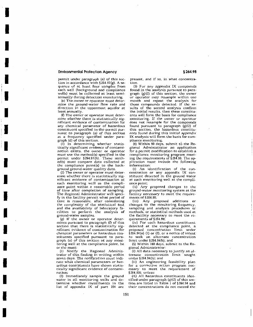
I I I I I I I I I I I I I I I I I I I
Environmental Protection Agency
permit under paragraph (a) of this section in accordance with §264.97(g). Asequence of at least four samples from each well (background and compliance wells) must be collected at least semiannually during detection monitoring.
(e) The owner or operator must determine the ground-water flow rate and direction in the uppermost aquifer at least annually.
(f) The owner or operator must determine whether there is statistically significant evidence of contamination for any chemical parameter of hazardous constituent specified in the permit pursuant to paragraph (a) of this section at a frequency specified under paragraph (d) of this section.
{I) In determining whether statistically significant evidence of contamination exists. the owner or operator must use the method(s) specified in the permit under §264.97(h). These method(s) must compare data collected at the compliance point(s) to the background ground-water quality data.
(2) The owner or operator must determine whether there is statistically significant evidence of contamination at each monitoring well as the compliance point within a reasonable period of time after completion of sampling. The Regional Administrator will specify in the facility permit what period of time is reasonable, after considering the complexity of the statistical test and the availability of laboratory facilities to perform the analysis of ground-water samples.
(g) If the owner or operator determines pursuant to paragraph (f) of this section that there is statistically significant evidence of contamination for chemical parameters or hazardous constituents specified pursuant to paragraph (a) of this section at any monitoring well at the compliance point, he or she must:
(I) Notify the Regional Administrator of this finding in writing within seven days. The notification must indicate what chemical parameters or hazardous constituents have shown statistically significant evidence of contamination:
(2) Immediately sample the gro1,1nd water in all monitoring wells and determine whether constituents in the list of appendix IX of part 264 are
191
§264.98
present, and if so, in what concentration.
(3) For any appendix IX compounds found in the analysis pursuant to paragraph (g) (2) of this section, the owner or operator may resample within one month and repeat the analysis for those compounds detected. If the results of the second analysis confirm the initial results, then these constituents will form the basis for compliance monitoring. If the owner or operator does not resample for the compounds found pursuant to paragraph (g)(2) of this section, the hazardous constituents found dur·ing this initial appendix IX analysis will form the basis for compliance monitoring.
(4) Within 90 days, submit to the Regional Administrator an application for a permit modification to establish a compliance monitoring program meeting the requirements of§ 264.99. The application must include the following information:
(i) An identification of the concentration or any appendix IX constituent detected in the ground water at each monitoring well at the compliance point;
(ii) Any proposed changes to the ground-water monitoring system at the facility necessary to meet the requirements of§264.99:
(iii) Any proposed additions or changes to the monitoring frequency, sampling and analysis procedures or methods, or statistical methods used at the facility necessary to meet the requirements of§ 264.99:
(iv) For each hazardous constituent detected at the compliance point, a proposed concentration limit under §264.94(a) {I) or (2), or a notice of intent to seek an alternate concentration limit under §264.94(b): and
(5) Within 180 days, submit to the Regional Administrator:
(i) All data necessary to justify an alternate concentration limit sought under § 264.94 (b): and
(ii) An engineering feasibility plan for a corrective action program necessary to meet the requirement of § 264. 100, unless:
(A) All hazardous constituents identified under paragraph (g)(2) of this section are listed in Table I of§ 264.94 and their concentrations do not exceed the
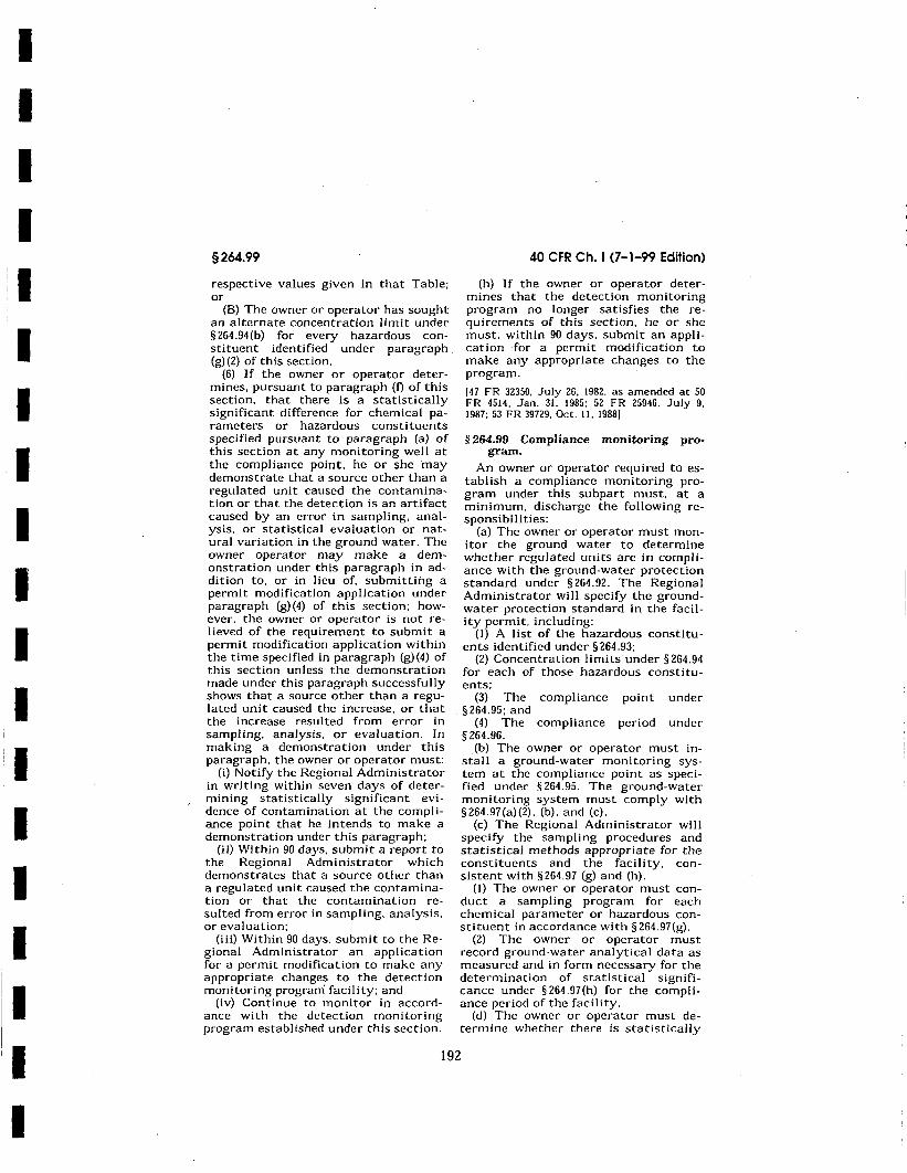
I I I I I
11 I I I I I I
I I I I
I
§264.99
respective values given in that Table; or
(B) The owner or operator has sought an alternate concentration limit under § 264.94(b) for every hazardous constituent identified under paragraph (g) (2) of this section.
(6) If the owner or operator determines, pursuant to paragraph (f) of this section, that there is a statistically significant difference for chemical parameters or hazardous constituents specified pursuant to paragraph (a) of this section at any monitoring well at the compliance point, he or she may demonstrate that a source other than a regulated unit caused the contamination or that the detection is an artifact caused by an error in sampling, analysis, or statistical evaluation or natural variation in the ground water. The owner operator may make a demonstration under this paragraph in addition to, or in lieu of, submitting a permit modification application under paragraph (g)(4) of this section; however, the owner or operator is not relieved of the requirement to submit a permit modification application within the time specified in paragraph (g) (4) of this section unless the demonstration made under this paragraph successfully shows that a source other than a regulated unit caused the increase, or that the increase resulted from error in sampling, analysis, or evaluation. In making a demonstration under this paragraph, the owner or operator must:
(i) Notify the Regional Administrator in writing within seven days of determining statistically significant evidence of contamination at the compliance point that he intends to make a demonstration under this paragraph;
(ii) Within 90 days, submit a report to the Regional Administrator which demonstrates that a source other than a regulated unit caused the contamination or that the contamination resulted from error in sampling, analysis, or evaluation;
(iii) Within 90 days. submit to the Regional Administrator an application for a permit modification to make any appropriate changes to the detection monitoring program facility; and
(iv) Continue to monitor in accordance with the detection monitoring program established under this section.
40 CFR Ch. I (7-1-99 Edition)
(h) If the owner or operator determines that the detection monitoring program no longer satisfies the requirements of this section, he or she must, within 90 days, submit an application for a permit modification to make any appropriate changes to the program.
(47 FR 32350, July 26, 1982, as amended at 50 FR 4514, Jan. 31, 1985; 52 FR 25946. July 9, 1987; 53 FR 39729, Oct. 11, 1988]
§ 264.99 Compliance monitoring program.
An owner or operator required to establish a compliance monitoring program under this subpart must, at a minimum, discharge the following responsibilities:
(a) The owner or operator must monitor the ground water to determine whether regulated units are in compliance with the ground-water protection standard under § 264.92. The Regional Administrator will specify the groundwater protection standard in the facility permit, including:
(I) A list of the hazardous constituents identified under §264.93;
(2) Concentration limits· under § 264.94 for each of those hazardous constituents;
(3) The compliance point under § 264.95; and
(4) The compliance period under § 264.96.
(b) The owner or operator must install a ground-water monitoring system at the compliance point as specified under § 264.95. The ground-water monitoring system must comply with §264.97(a)(2), (b), and (c).
(c) The Regional Administrator will specify the sampling procedures and statistical methods appropriate for the constituents and the facility, consistent with §264.97 (g) and (h).
(I) The owner or operator must conduct a sampling program for each chemical parameter or hazardous constituent in accordance with §264.97(g).
(2) The owner or operator must record ground-water analytical data as measured and in form necessary for the determination of statistical significance under §264.97(h) for the compliance period of the facility.
(d) The owner or operator must determine whether there is statistically
192
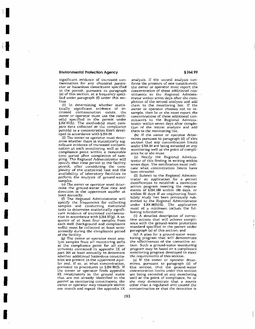
I I I I I I I I I I I I I I I I I I
Environmental Protection Agency
significant evidence of increased contamination for any chemical parameter or hazardous constituent specified in the permit, pursuant to paragraph (a) of this section, at a frequency specified under paragraph. (0 under this section.
·(I) In determining whether statistically significant evidence of increased contamination exists, the owner or operator must use the method(s) specified in the permit under §264.97(h). The methods(s) must compare data collected at the compliance point(s) to a concentration limit developed in accordance with§ 264.94.
(2) The owner or operator must determine whether there is statistically significant evidence of increased contamination at each monitoring well at the compliance point within a reasonable time period after completion of sampling. The Regional Administrator will specify that time period in the facility permit, after considering the complexity of the statistical test and the availability of laboratory facilities to perform the analysis of ground-water samples.
(e) The owner or operator must determine the ground-water flow rate and direction in the uppermost aquifer at least annually.
(f) The Regional Administrator will specify the frequencies for collecting samples and conducting statistical tests to determine statistically significant evidence of increased contamination in accordance with§ 264.97(g). Asequence of at least four samples from each well (background and compliance wells) must be collected at least semiannually during the compliance period of the facility.
(g) The owner or opera tor must ana-1 yze samples from all monitoring wells at the compliance point for all constituents contained in appendix IX of part 264 at least annually to determine whether additional hazardous constituents are present in the uppermost aquifer and, if so, at what concentration, pursuant to procedures in §264.98(f). If the owner or operator finds appendix IX constituents in the ground water that are not already identified in the permit as monitoring constituents, the owner or operator may resample within one month and repeat the appendix IX
§264.99
analysis. If the second analysis confirms the presence of new constituents, the owner or operator must report the concentration of these additional constituents to the Regional Administrator within seven days after the completion of the second analysis and add them to the monitoring list. If the owner or operator chooses not to resample, then he or she must report the concentrations of these additional constituents to the Regional Administrator within seven days after completion of the intiial analysis and add them to the monitoring list.
(h) If the owner or operator determines pursuant to paragraph (d) of this section that any concentration limits under§ 264.94 are being exceeded at any monitoring well at the point .of compliance he or she must:
(I) Notify the Regional Administrator of this finding in writing within seven days. The notification must indicate what concentration limits have been exceeded.
(2) Submit to the Regional Administrator an application for a permit modification to establish a corrective action program meeting the requirements of § 264. IOO within 180 days, or within 90 days if an engineering feasibility study has been previously submitted to the Regional Administrator under §264.98(h)(5). The application must at a minimum include the following information:
(i) A detailed description of corrective actions that will achieve compliance with the ground-water protection standard specified in the permit under paragraph (a) of this section; and
(ii) A plan for a ground-water monitoring program that will demonstrate the effectiveness of the corrective action. Such a ground-water monitoring program may be based on a compliance monitoring program developed to meet the requirements of this section.
(i) If the owner or operator determines, pursuant to paragraph (d) of this section, that the ground-water concentration limits under this section are being exceeded at any monitoring well at the point of compliance, he or she may demonstrate that a source other than a regulated unit caused the contamination or that the detection is
193
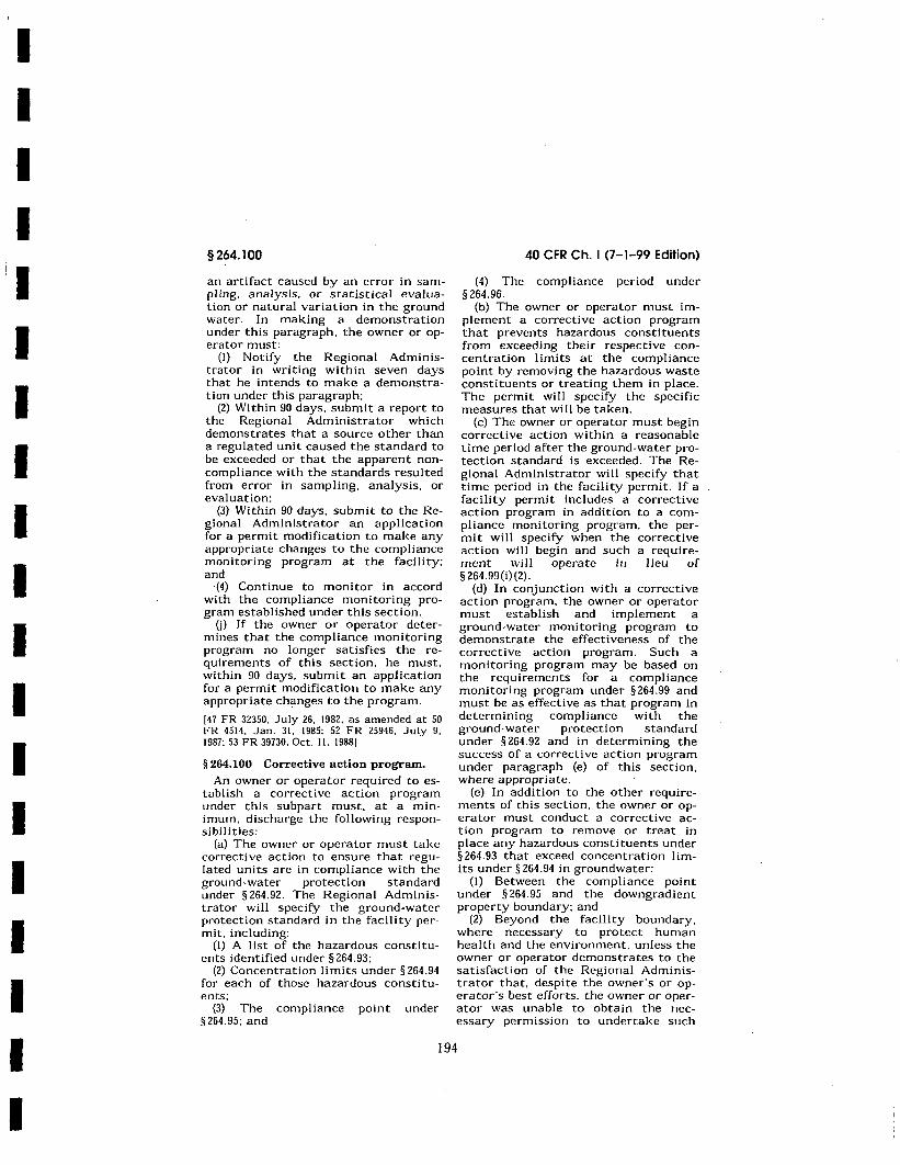
I I I I I I I I I I I I I I I I I I I
§264.100
an artifact caused by an error in sampling, analysis, or statistical evaluation or natural variation in the ground water. In making a demonstration under this paragraph, the owner or operator must:
(I) Notify the Regional Administrator in writing within seven days that he intends to make a demonstration under this paragraph;
(2) Within 90 days, submit a report to the Regional Administrator which demonstrates that a source other than a regulated unit caused the standard to be exceeded or that the apparent noncompliance with the standards resulted from error in sampling, analysis, or evaluation:
(3) Within 90 days, submit to the Regional Administrator an application for a permit modification to make any appropriate changes to the compliance monitoring program at the facility: and
-(4) Continue to monitor in accord with the compliance monitoring program established under this section.
U) If the owner or operator determines that the compliance monitoring program no longer satisfies the requirements of this section, he must, within 90 days, submit an application for a permit modification to make any appropriate changes to the program.
[47 FR 32350. July 26, 1982, as amended at 50 FR 4514, Jan. 31. 1985: 52 FR 25946. July 9, 1987; 53 FR 39730, Oct. 1 I. 1988)
§ 264.100 Corrective action program.
An owner or operator required to establish a corrective action program under this subpart must. at a minimum, discharge the following responsibilities:
(a) The owner or operator must take corrective action to ensure that regulated units are in compliance with the ground-water protection standard under § 264.92. The Regional Administrator will specify the ground-water protection standard in the facility permit, including:
(I) A list of the hazardous constituents identified under § 264.93:
(2) Concentration limits under§ 264.94 for each of those hazardous constituents;
(3) The compliance point under §264.95; and
40 CFR Ch. I (7-1-99 Edition)
(4) The compliance period under § 264.96.
(b) The owner or operator must implement a corrective action program that prevents hazardous constituents from exceeding their respective concentration limits at the compliance point by removing the hazardous waste constituents or treating them in place. The permit will specify the specific measures that will be taken.
(c) The owner or operator must begin corrective action within a reasonable time period after the ground-water protection standard is exceeded. The Regional Administrator will specify that time period in the facility permit. If a facility permit includes a corrective action program in addition to a compliance monitoring program, the permit will specify when the corrective action will begin and such a requirement will operate in lieu of § 264.99(i)(2).
(d) In conjunction with a corrective action program. the owner or operator must establish and implement a ground-water monitoring program to demonstrate the effectiveness of the corrective action program. Such a monitoring program may be based on the requirements for a compliance monitoring program under §264.99 and must be as effective as that program in determining compliance with the ground-water protection standard under § 264.92 and in determining the success of a corrective action program under paragraph (e) of this section, where appropriate.
(e) In addition to the other requirements of this section, the owner or operator must conduct a corrective action program to remove or treat in place any hazardous constituents under §264.93 that exceed concentration limits under§ 264.94 in groundwater:
(I) Between the compliance point under §264.95 and the downgradient property boundary: and
(2) Beyond the facility boundary, where necessary to protect human health and the environment, unless the owner or operator demonstrates to the satisfaction of the Regional Administrator that, despite the owner's or operator's best efforts, the owner or operator was unable to obtain the necessary permission to undertake such
194
I I I I I I I I I I I I I I I I I I I
§264.110
§264.110 Applicability.
Except as§ 264.1 provides otherwise: (a) Sections 264. 111 through 264 .115
(which concern closure) apply to the owners and operators of all hazardous waste management facilities: and
(b) Sections 264.116 through 264.120 (which concern post-closure care) apply to the owners and operators of:
(I) All hazardous waste disposal fa-cilities: ·
(2) Waste piles and surface impoundments from which the owner or operator intends to remove the wastes at closure to the extent that these sections are made applicable to such facilities in § 264.228 or§ 264.258:
(3) Tank systems that are required under §264.197 to meet the requirements for landfills; and
(4) Containment buildings that are required under§ 264.1102 to meet the requirement for landfills.
(c) The Regional Administrator may replace all or part of the requirements of this subpart (and the unit-specific standards referenced in § 264. 111 (c) applying to a regulated unit), with alternative requirements set out in a permit or in an enforceable document (as defined in 40 CFR 270.l(c)(7)). where the Regional Administrator determines that:
(I) The regulated unit is situated among solid waste management units (or areas of concern). a release has occurred, and both the regulated unit and one or more solid waste management unit(s) (or areas of concern) are likely to have contributed to the release: and
(2) It is not necessary to apply the closure requirements of this subpart (and those referenced herein) because the alternative requirements will protect human health and the environment and will satisfy the closure performance standard of § 264 .111 (a) and (b).
(51 FR 16444, May 2. 1986, as amended at 51 FR 25472, July 14. 1986: 57 FR 37264, Aug. 18, 1992: 63 FR 56733. Oct. 22. 1998)
§ 264.111 Closure performance standard.
The owner or operator must close the facility in a manner that:
(a) Minimizes the need for further maintenance: and
40 CFR Ch. I (7-1-99 Edition)
(b) Controls. minimizes or eliminates. to the extent necessary to protect human health and the environment, post-closure escape of hazardous waste, hazardous constituents, leachate, contaminated run-off. or hazardous waste decomposition products to the ground or surface waters or to the atmosphere: and
(c) Complies with the closure requirements of this subpart. including. but not limited to. the requirements of §§264.178, 264.197, 264.228. 264.258, 264.280, 264.310. 264.351. 264.601 through 264.603. and 264.1102.
[51 FR 16444, May 2, 1986, as amended at 52 FR 46963, Dec. 10, 1987: 57 FR 37265, Aug. 18, 1992]
§ 264.112 Closure plan; amendment of plan.
(a) Written plan. (I) The owner or operator of a hazardous waste management facility must have a written closure plan. In addition, certain surface impoundments and waste piles from which the owner or operator intends to remove or decontaminate the hazardous waste at partial or final closure are required by §§ 264.228(c) (l)(i) and 264.258(c)(l)(i) to have contingent closure plans. The plan must be submitted with the permit application. in accordance with §270.14(b)(13) of this chapter, and approved by the Regional Administrator as part of the permit issuance procedures under part I 24 of this chapter. In accordance with §270.32 of this chapter, the approved closure plan will become a condition of any RCRA permit.
(2) The Director·s approval of the plan must ensure that the approved closure plan is consistent with §§ 264.111 through 264.115 and the applicable requirements of subpart F of this part. §§264.178. 264.197. 264.228, 264.258, 264.280, 264.310. 264.351. 264.601, and 264.1102. Until final closure is completed and certified in accordance with §264.115. a copy of the approved plan and all approved revisions must be furnished to the Director upon request, including requests by mail.
(b) Content of plan. The plan must identify steps necessary to perform partial and/or final closure of the facility at any point during its active life. The closure plan must include. at least:
196
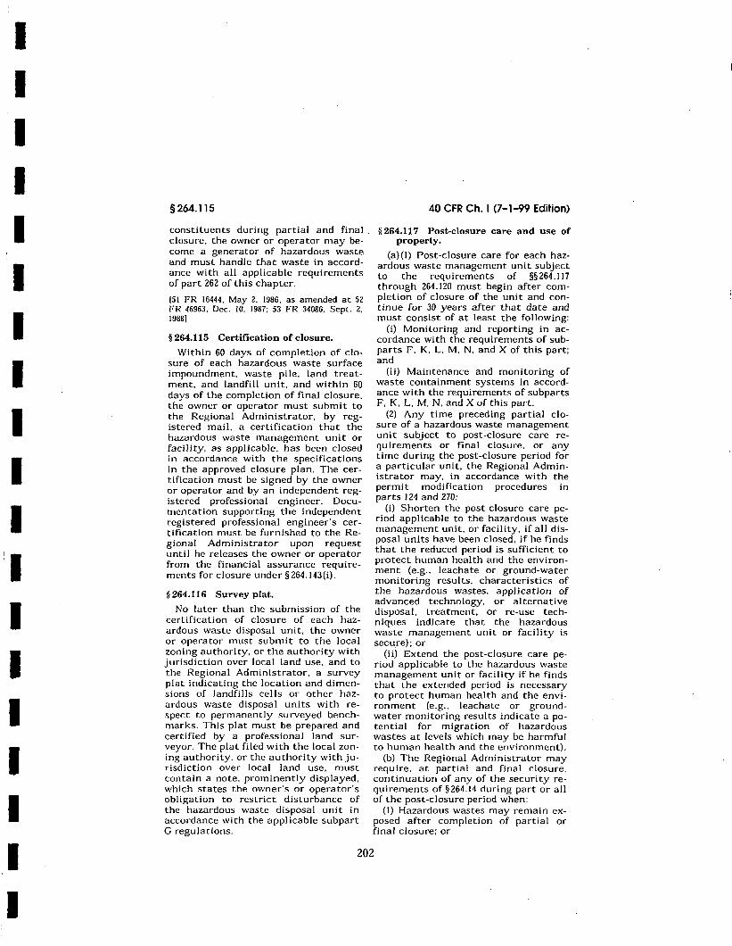
I I I I I I I I I I I
I I I I I I I
§264.115
constituents during partial and final . closure, the owner or operator may become a generator of hazardous waste and must handle that waste in accordance with all applicable requirements of part 262 of this chapter.
(51 FR 16444, May 2, 1986, as amended at 52 FR 46963, Dec. JO, 1987; 53 FR 34086, Sept. 2, 1988)
§ 264.115 Certification of closure.
Within 60 days of completion of closure of each hazardous waste surface impoundment, waste pile, land treatment, and landfill unit, and within 60 days of the completion of final closure, the owner or operator must submit to the Regional Administrator, by registered mail, a certification that the hazardous waste management unit or facility, as applicable, has been closed in accordance with the specifications in the approved closure plan. The certification must be signed by the owner or operator and by an independent registered professional engineer. Documentation supporting the independent registered professional engineer·s certification must be furnished to the Regional Administrator upon request until he releases the owner or operator from the financial assurance requirements for closure under §264.143(i).
§ 264.116 Survey plat.
No later than the submission of the certification of closure of each hazardous waste disposal unit, the owner or operator must submit to the local zoning authority, or the authority with jurisdiction over local land use, and to the Regional Administrator, a survey plat indicating the location and dimensions of landfills cells or other hazardous waste disposal units with respect to permanently surveyed benchmarks. This plat must be prepared and certified by a professional land surveyor. The plat filed with the local zoning authority. or the authority with jurisdiction over local land use, must contain a note, prominently displayed, which states the owner's or operator's obligation to restrict disturbance of the hazardous waste disposal unit in accordance with the applicable subpart G regulations.
40 CFR Ch. I (7-1-99 Edition)
§ 264.117 Post-closure care and use of property.
(a)(I) Post-closure care for each hazardous waste management unit subject to the requirements of §§ 264 .117 through 264.120 must begin after completion of closure of the unit and continue for 30 years after that date and must consist of at least the following:
(i) Monitoring and reporting in accordance with the requirements of subparts F, K, L. M, N, and X of this part; and
(ii) Maintenance and monitoring of waste containment systems in accordance with the requirements of subparts F, K, L: M, N, and X of this part.
(2) Any time preceding partial closure of a hazardous waste management unit subject to post-closure care requirements or final closure, or any time during the post-closure period for a particular unit, the Regional Administrator may, in accordance with the permit modification procedures in parts 124 and 270:
(i) Shorten the post-closure care period applicable to the hazardous waste management unit, or facility, if all disposal units have been closed, if he finds that the reduced period is sufficient to protect human health and the environment (e.g .. leachate or ground-water monitoring results, characteristics of the hazardous wastes. application of advanced technology, or alternative disposal, treatment, or re-use techniques indicate that the hazardous waste management unit or facility is secu_re); or
(ii) Extend the post-closure care period applicable to the hazardous waste management unit or facility if he finds that the extended period is necessary to protect human health and the environment (e.g., leachate or groundwater monitoring results indicate a potential for migration of hazardous wastes at levels which may be harmful to human health and the environment).
(b) The Regional Administrator may require, at partial and final closure, continuation of any of the security requirements of§ 264.14 during part or all of the post-closure period when;
(I) Hazardous wastes may remain exposed after completion of partial or final closure; or
202
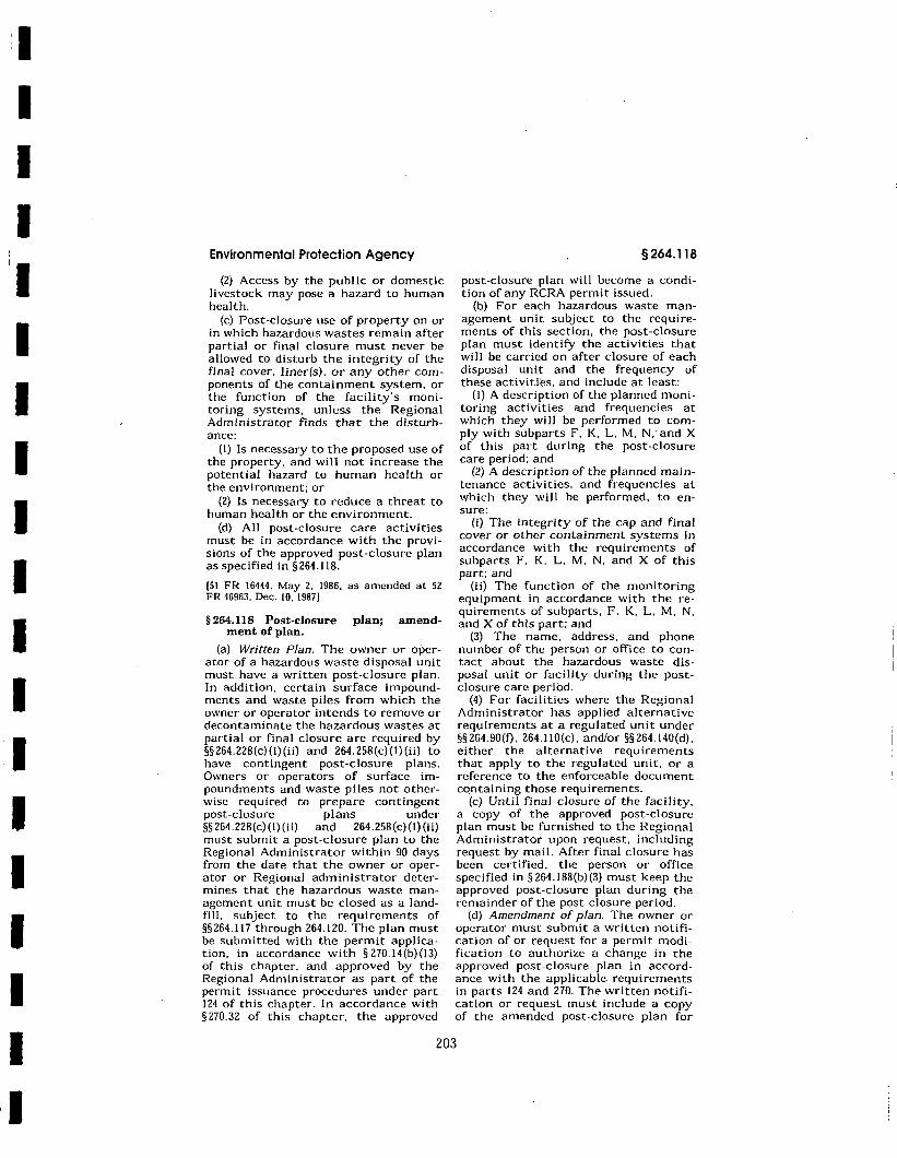
I I I I I I I I I I I I I I I I I I I
Environmental Protection Agency
(2) Access by the public or domestic livestock may pose a hazard to human health.
(c) Post-closure use of property on or in which hazardous wastes remain after partial or final closure must never be allowed to disturb the integrity of the final cover, liner(s). or any other components of the containment system, or the function of the facility's monitoring systems, unless the Regional Administrator finds that the disturbance:
(I) Is necessary to the proposed use of the property, and will not increase the potential hazard to human health or the environment; or
(2) Is necessary to reduce a threat to human health or the environment.
(d) All post-closure care activities must be in accordance with the provisions of the approved post-closure plan as specified in § 264.118.
(51 FR 16444, May 2, 1986, as amended at 52 FR 46963, Dec. 10, 1987]
§ 264.118 Post-closure plan; amendment of plan.
(a) Written Plan. The owner or operator of a hazardous waste disposal unit must have a written post-closure plan. In addition, certain surface impoundments and waste piles from which the owner or operator intends to remove or decontaminate the hazardous wastes at partial or final closure are required by §§ 264.228(c) (l)(ii) and 264.258(c)(I) (ii) to have contingent post-closure plans. Owners or oper-ators of surface impoundments and waste piles not otherwise required to prepare contingent post-closure plans under §§264.228(c)(l)(ii) and 264.258(c)(l)(ii) must submit a post-closure plan to the Regional Administrator within 90 days from the date that the owner or operator or Regional administrator determines that the hazardous waste management unit must be closed as a landfill, subject to the requirements of §§ 264.117 through 264.120. The plan must be submitted with the permit application, in accordance with §270.14(b)(l3) of this chapter. and approved by the Regional Administrator as part of the permit issuance procedures under part 124 of this chapter. In accordance with § 270.32 of this chapter, the approved
§ 264.118
post-closure plan will become a condition of any RCRA permit issued.
(b) For each hazardous waste management unit subject to the requirements of this section, the post-closure plan must identify the activities that will be carried on after closure of each disposal unit and the frequency of these activities, and include at least:
(I) A description of the planned monitoring activities and frequencies at which they will be performed to comply with subparts F, K, L. M, N,· and X of this part during the post-closure care period; and
(2) A description of the planned maintenance activities, and frequencies at which they will be performed, to ensure:
(i) The integrity of the cap and final cover or other containment systems in accordance with the requirements of subparts F, K. L, M, N, and X of this part; and
(ii) The function of the monitoring equipment in accordance with the requirements of subparts, F. K, L, M. N, and X of this part; and
(3) The name, address. and phone number of the person or office to contact about the hazardous waste disposal unit or facility during the postclosure care period.
(4) For facilities where the Regional Administrator has applied alternative requirements at a regulated unit under §§264.90(f). 264.I!O(c). and/or §§264.140(d), either the alternative requirements that apply to the regulated unit, or a reference to the enforceable document containing those requirements.
(c) Until final closure of the facility. a copy of the approved post-closure plan must be furnished to the Regional Administrator upon request, including request by mail. After final closure has been certified. the person or office specified in § 264. I88(b)(3) must keep the approved post-closure plan during the remainder of the post-closure period.
(d) Amendment of plan. The owner or operator must submit a written notification of or request for a permit modification to authorize a change in the approved post-closure plan in accordance with the applicable requirements in parts 124 and 270. The written notification or request must include a copy of the amended post-closure plan for
203
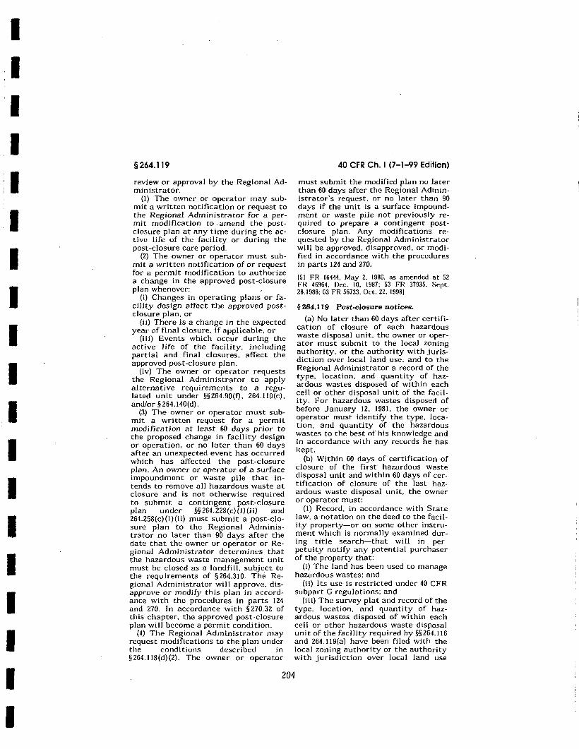
I I I I I I I I I I I I I I I I I I I
§264.119
review or approval by the Regional Administrator.
(I) The owner or operator may submit a written notification or request to the Regional Administrator for a permit modification to .amend the postclosure plan at any time during the active life of the facility or during the post-closure care period.
(2) The owner or operator must submit a written notification of or request for a permit modification to authorize a change in the approved post-closure plan whenever:
(i) Changes in operating plans or facility design affect the approved postclosure plan. or
(ii) There is a change in the expected year of final closure, if applicable, or
(iii) Events which occur during the active life of the facility, including partial and final closures, affect the approved post-closure plan.
(iv) The owner or operator requests the Regional Administrator to apply alternative requirements to a regulated unit under §§ 264.90(f). 264.1 IO(c). and/or §264.140(d).
(3) The owner or operator must submit a written request for a permit modification at least 60 days prior to the proposed change in facility design or operation, or no later than 60 days after an unexpected event has occurred which has affected the post-closure plan. An owner or operator of a surface impoundment or waste pile that intends to remove all hazardous waste at closure and is not otherwise required to submit a contingent post-closure plan under §§264.228(c)(J)(ii) and 264.258(c)(l)(ii) must submit a post-closure plan to the Regional Administrator no later than 90 days after the date that the owner or operator or Regional Administrator determines that the hazardous waste management unit must be closed as a landfill. subject to the requirements of §264.310. The Regional Administrator will approve. disapprove or modify this plan in accordance with the procedures in parts I 24 and 270. In accordance with § 270.32 of this chapter. the approved post-closure plan will become a permit condition.
(4) The Regional Administrator may request modifications to the plan under the conditions described in §264.118(d)(2). The owner or operator
40 CFR Ch. I (7-1-99 Edition)
must submit the modified plan no later than 60 days after the Regional Administrator·s request. or no later than 90 days if the unit is a surface impoundment or waste pile not previously required to prepare a contingent postclosure plan. Any modifications requested by the Regional Administrator will be approved, disapproved. or modified in accordance with the procedures in parts 124 and 270.
(51 FR 16444. May 2. 1986, as amended at 52 FR 46964. Dec. 10. 1987; 53 FR 37935. Sept. 28.1988; 63 FR 56733. Oct. 22. 1998)
§ 264.119 Post-closure notices.
(a) No later than 60 days after certification of closure of each hazardous waste disposal unit. the owner or operator must submit to the local zoning authority. or the authority with jurisdiction over local land use, and to the Regional Administrator a record of the type, location, and quantity of hazardous wastes disposed of within each cell or other disposal unit of the facility. For hazardous wastes disposed of before January 12, 1981. the owner or operator must identify the type. location. and quantity of the hazardous wastes to the best of his knowledge and in accordance with any records he has kept.
(b) Within 60 days of certification of closure of the first hazardous waste disposal unit and within 60 days of certification of closure of the last hazardous waste disposal unit, the owner or operator must:
(I) Record, in accordance with State law. a notation on the deed to the facility property-or on some other instrument which is normally examined during title search-that will in perpetuity notify any potential purchaser of the property that:
(i) The land has been used to manage hazardous wastes; and
(ii) Its use is restricted under 40 CFR subpart G regulations; and
(iii) The survey plat and record of the type, location, and quantity of hazardous wastes disposed of within each cell or other hazardous waste disposal unit of the facility required by §§264.116 and 264. l l 9(a) have been filed with the local zoning authority or the authority with jurisdiction over local land use
204
I I I I I I I I I I I I I I I I I I I
Environmental Protection Agency
and with the Regional Administrator; and
(2) Submit a certification, signed by the owner or operator, that he has recorded the notation specified in paragraph (b)(J) of this section, including a copy of the document in which the notation has been placed. to the Regional Administrator.
(c) If the owner or operator or any subsequent owner or operator of the land upon which a hazardous waste disposal unit is located wishes to remove hazardous wastes and hazardous waste residues. the liner, if any, or contaminated soils. he must request a modification to the post-closure permit in accordance with the applicable requirements in parts 124 and 270. The owner or operator must demonstrate that the removal of hazardous wastes will satisfy the criteria of § 264.117(c). By removing hazardous waste, the owner or operator may become a generator of hazardous waste and must manage it in accordance with all applicable requirements of this chapter. If he is granted a permit modification or otherwise granted approval to conduct such removal activities, the owner or operator may request that the Regional Adminc istrator approve either:
(I) The removal of the notation cin the deed to the facility property or other instrument normally examined during title search; or
(2) The addition of a notation to the deed or instrument indicating the removal of the hazardous waste.
§ 264.120 Certification of completion of post-closure care.
No later than 60 days after completion of the established post-closure care period for each hazardous waste disposal unit. the owner or operator must submit to the Regional Administrator, by registered mail. a certification that the post-closure care period for the hazardous waste disposal unit was performed in accordance with the specifications in the approved post-closure plan. The certification must be signed by the owner or operator and an independent registered professional engineer. Documentation supporting the independent registered professional engineer's certification must be furnished to the Regional Administrator upon re-
§264.140
quest until he releases the owner or operator from the financial assurance requirements for post-closure care under §264.145(i).
Subpart H-Financial Requirements
SOURCE: 47 FR 15047, Apr. 7. 1982. unless otherwise noted.
§ 264.140 Applicability.
(a) The requirements of §§ 264.142, 264.143, and 264. 147 through 264.151 apply to owners and operators of all hazardous waste facilities. except as provided otherwise in this section or in § 264.1.
{b) The requirements of §§264.144 and 264.145 apply only to owners and operators of:
(I) Disposal facilities: (2) Piles, and surface impoundments
from which the owner or operator intends to remove the wastes at closure, to the extent that these sections are made applicable to such facilities in §§ 264.228 and 264.258;
(3) Tank systems that are required under § 264. 197 to meet the requirements for landfills; and
(4) Containment buildings that are required under §264.1102 to meet the requirements for landfills.
(c) States and the Federal government are exempt from the requirements of this subpart.
{d) The Regional Administrator may replace all or part of the requirements of this subpart applying to a regulated unit with alternative requirements for financial assurance set out in the permit or in an enforceable document (as defined in 40 CFR 270.l{c)(7)). where the Regional Administrator:
{I) Prescribes alternative requirements for the regulated unit under § 264.90(1) and/or§ 264.1 IO(d); and
(2) Determines that it is not necessary to apply the requirements of this subpart because the alternative financial assurance requirements will protect human health and the environment.
{47 FR 15047, Apr. 7. 1982, as amended at 47 FR 32357. July 26, 1982; 51 FR 25472. July 14, 1986: 57 FR 37265. Aug. 18, 1992: 63 FR 56733, Oct. 22, 1998]
205
I I I I I I I I I.
I I I I I I I I I I
Environmental Protection Agency
(4) The effectiveness of additional treatment, design. or monitoring techniques.
(b} The Regional Administrator may determine that additional design. operating, and monitoring requirements are necessary for land treatment facilities managing hazardous wastes FO20, FO2I, FO22, FO23, FO26. and FO27 in order to reduce the possibility of migration of these wastes to ground water, surface water. or air so as to protect human health and the environment.
[50 FR 2004, Jan. 14, 1985]
Subpart N-Landfills
SOURCE: 47 FR 32365, July 26, 1982, unless otherwise noted.
§ 264.300 Applicability.
The regulations in this subpart apply to owners and operators of facilities that dispose of hazardous waste in landfills, except as § 264.1 provides otherwise.
§ 264.301 Design and operating requirements.
(a) Any landfill that is not covered by paragraph (c) of this section or § 265.301 (a) of this chapter must have a liner system for all portions of the landfill (except for existing portions of such landfill). The liner system must have:
(I) A liner that is designed, constructed, and installed to prevent any migration of wastes out of the landfill to the adjacent subsurface soil or ground water or surface water at anytime during the active life (including the closure period) of the landfill. The liner must be constructed of materials that prevent wastes from passing into the liner during the active life of the facility. The liner must be:
(i) Constructed of materials that have appropriate chemical properties and sufficient strength and thickness to prevent failure due to pressure gradients (including static head and external hydrogeologic forces). physical contact with the waste or leachate to which they are exposed, climatic conditions, the stress of installation, and the stress of daily operation;
§264.301
(ii) Placed upon a foundation or base capable of providing support to the liner and resistance to pressure gradients above and below the liner to prevent failure of the liner due to settlement, compression. or uplift; and
(iii} Installed to cover all surrounding earth likely to be in contact with the waste or leachate; and
(2) A leachate collection and removal system immediately above the liner that is designed, constructed, maintained, and operated to collect and remove leachate from the landfill. The Regional Administrator will specify design and operating conditions in the permit to ensure that the leachate depth over the liner does not exceed 30 cm (one foot). The leachate collection and removal system must be:
(i) Constructed of materials that are: (A) Chemically resistant to the waste
managed in the landfill and the leachate expected to be generated; and
(8) Of sufficient strength and thickness to prevent collapse under the pressures exerted by overlying wastes, waste cover materials. and by any equipment used at the landfill; and
(ii) Designed and operated to function without clogging through the scheduled closure of the landfill.
(b) The owner or operator will be exempted from the requirements of paragraph (a) of this section if the Regional Administrator finds, based on a demonstration by the owner or operator, that alternative design and operating practices, together with location characteristics. will prevent the migration of any hazardous cons ti tucnts (see § 264.93) into the ground water or surface water at any future time. In deciding whether to grant an exemption, the Regional Administrator will consider:
(I) The nature and quantity of the wastes;
(2) The proposed alternate design and operation;
(3) The hydrogeologic setting of the facility. including the attenuative capacity and thickness of the liners and soils present between the landfill and ground water or surface water; and
(4) All other factors which would influence the quality and mobility of the leachate produced and the potential for it to migrate to ground water or surface water.
291
I I I I I I I I I I I I I I I I I I I
§264.301
{c) The owner or operator of each new landfill unit on which construction commences after January 29. 1992. each lateral expansion of a landfill unit on which construction commences after July 29. 1992, and each replacement of an existing landfill unit that is to commence reuse after July 29. 1992 must install two or more liners and a leachate collection and removal system above and between such liners. "Construction commences" is as defined in § 260. IO of this chapter under "existing facility".
{I) (i) The liner system must include: (A) A top liner designed and con
structed of materials (e.g., a geomembrane) to prevent the migration of hazardous constituents into such liner during the active life and post-closure care period; and
(B) A composite bottom liner. consisting of at least two components. The upper component must be designed and constructed of materials (e.g., a geomembrane) to prevent the migration of hazardous constituents into this component during the active life and post-closure care period. The lower component must be designed and constructed of materials to minimize the migration of hazardous constituents if a breach in the upper component were to occur. The lower component must _be constructed of at least 3 feet (91 cm) of compacted soil material with a hydraulic conductivity of no more than lxI0- 7
cm/sec. (ii) The liners must comply with
paragraphs (a){I) (i). (ii). and (iii) of this section.
(2) The leachate collection and removal system immediately above the top liner must be designed. constructed. operated. and maintained to collect and remove leachate from the landfill during the active life and post-closure care period. The Regional Administrator will specify design and operating conditions in the permit to ensure that the leachate depth over the liner does not exceed 30 cm (one foot). The leachate collection and removal system must comply with paragraphs (3)(c) (iii) and (iv) of this section.
(3) The leachate collection and removal system between the liners. and immediately above the bottom composite liner in the case of multiple leachate collection and removal systems, is also
40 CFR Ch. I (7-1-99 Edition)
a leak detection system. This leak detection system must be capable of detecting, collecting. and removing leaks of hazardous constituents at the earliest practicable time through all areas of the top liner likely to be exposed to waste or leachate during the active life and post-closure care period. The requirements for a leak detection system in this paragraph are satisfied by installation of a system that is, at a minimum:
(i) Constructed with a bottom slope of one percent or more;
{ii) Constructed of granular drainage materials with a hydraulic conductivity of lxI0- 2 cm/sec or more and a thickness of 12 inches (30.5 cm) or more; or constructed of synthetic or geonet drainage materials with a transmissivity of 3xI0- 5 m 2/sec or more;
(iii) Constructed of materials that are chemically resistant to the waste managed in the landfill and the leachate expected to be generated, and of sufficient strength and thickness to prevent collapse under the pressures exerted by overlying wastes, waste cover materials. and equipment used at the landfill;
(iv) Designed and operated to minimize clogging during the active life and post-closure care period; and
(v) Constructed with sumps and liquid removal methods (e.g .. pumps) of sufficient size to collect and remove liquids from the sump and prevent liquids from backing up into the drainage layer. Each unit must have its own sump(s). The design of each sump and removal system must provide a method for measuring and recording the volume of liquids present in the sump and of liquids removed.
(4) The owner or operator shall collect and remove pumpable liquids in the leak detection system sumps to minimize the head on the bottom liner.
(5) The owner or operator of a leak detection system that is not located completely above the seasonal high water table must demonstrate that the operation of the leak detection system will not be adversely affected by the presence of ground water.
(d) The Regional Administrator may approve alternative design or operating
292
I I I I I I I I I I I I I I I I I
I
Environmental Protection Agency
practices to those specified in paragraph (c) of this section if the owner or operator demonstrates to the Regional Administrator that such design and operating practices, together with location characteristics:
(I) Will prevent the migration of any hazardous constituent into the ground water or surface water at least as effectively as the liners and leachate collection and removal systems specified in paragraph (c) of this section: and
(2) Will allow detection of leaks of hazardous constituents through the top liner at least as effectively.
(e) The double liner requirement set forth in paragraph (c) of this section may be waived by the Regional Administrator for any monofill, if:
(I) The monofill contains only hazardous wastes from foundry furnace emission controls or metal casting molding sand, and such wastes do not contain constituents which would render the wastes hazardous for reasons other than the Toxicity Characteristic in §261.24 of this chapter, with EPA Hazardous Waste Numbers 0004 through 0017; and
(2)(i)(A) The monofill has at least one liner for which there is no evidence that such liner is leaking:
(B) The monofill is located more than one-quarter mile from an underground source of drinking water (as that term is defined in§ 144.3 of this chapter): and
(C) The monofi II is in compliance with generally applicable ground-water monitoring requirements for facilities with permits under RCRA 3005(c); or
(ii) The owner or operator demonstrates that the monofill is located, designed and operated so as to assure that there will be no migration of any hazardous constituent into ground water or surface water. at any future time.
(f) The owner or operator of any replacement landfill unit is exempt from paragraph (c) of this section if:
{I) The existing unit was constructed in compliance with the design standards of section 3004(0) (l)(A)(i) and (o)(5) of the Resource Conservation and Recovery Act; and
(2) There is no reason to believe that the liner is not functioning as designed.
§264-302
(g) The owner or operator must design, construct, operate, and maintain a run-on control system capable of preventing flow onto the active portion of the landfill during peak discharge from at least a 25-year storm.
(h) The owner or operator must design, construct, operate, and maintain a run-off management system to collect and control at least the water volume resulting from a _24-hour, 25-year storm.
(i) Collection and holding facilities (e.g., tanks or basins) associated with run-on and run-off control systems must be emptied or otherwise managed expeditiously after storms to maintain design capacity of the system.
(j) If the landfill contains any particulate matter which may be subject to wind dispersal, the owner or operator must cover or otherwise manage the landfill to control wind dispersal.
(k) The Regional Administrator will specify in the permit all design and operating practices that are necessary to ensure that the requirements of this section are satisfied.
(I) Any permit under RCRA 3005(c) which is issued for a landfill located within the State of Alabama shall require the installation of two or more liners and a leachate collection system above and between such liners, notwithstanding any other provision of RCRA.
[47 FR 32365. July 26, 1982, as amended at 50 FR 4514, Jan. 31, 1985; SO FR 28748, July 15, 1985: 55 FR I 1875, Mar. 29, 1990: 57 FR 3489. Jan. 29. 1992]
§ 264.302 Action leakage rate.
(a) The Regional Administrator shall approve an action leakage rate for surface impoundment units subject to § 264.301 (c) or (d). The action leakage rate is the maximum design flow rate that the leak detection system (LDS) can remove without the fluid head on the bottom liner exceeding I foot. The action leakage rate must include an adequate safety margin to allow for uncertainties in the design (e.g., slope, hydraulic conductivity, thickness of drainage material), construction, operation, and location of the LOS, waste and leachate characteristics, I ikelihood and amounts of other sources of
293
I I I I I I I I I I I I I I I I I I I
§264.303
liquids in the LOS. and proposed response actions (e.g .. the action leakage rate must consider decreases in the flow capacity of the system over time resulting from siltation and clogging, rib layover and creep of synthetic components of the system, overburden pressures, etc.).
(b) To determine if the action leakage rate has been exceeded, the owner or operator must convert the weekly or monthly flow rate from the monitoring data obtained under § 264.303(c). to an average daily flow rate (gallons per acre per day) for each sump. Unless the Regional Administrator approves a different calculation, the average daily flow rate for each sump must be calculated weekly during the active life and closure period, and monthly during the post-closure care period when monthly monitoring is required under § 264.303(c).
(57 FR 3490, Jan. 29, 1992]
§ 264.303 Monitoring and inspection. (a) During construction or installa
tion, liners (except in the case of existing portions of landfills exempt from § 264.301 (a)) and cover systems (e.g., membranes, sheets, or coatings) must be inspected for uniformity, damage. and imperfections (e.g.. holes. cracks, thin spots, or foreign materials). Immediately after construction or installation:
(I) Synthetic liners and covers must be inspected to ensure tight seams and joints and the absence of tears, punctures, or blisters; and
(2) Soil-based and admixed liners and covers must be inspected for imperfections including lenses, cracks. channels, root holes, or other structural non-uniformities that may cause an innease in the permeability of the liner or cover.
(b) While a landfill is in operation, it must be inspected weekly and after storms to detect evidence of any of the following:
(I) Deterioration, malfunctions. or improper operation of run-on and runoff control systems;
(2) Proper functioning of wind dispersal control systems, where present; and
(3) The presence of leachate in and proper functioning of leachate collec-
40 CFR Ch. I (7-1-99 Edition)
tion and removal systems, where present.
(c)(I) An owner or operator required to have a leak detection system under § 264.301 (c) or (d) must record the amount of liquids removed from each leak detection system sump at least once each week during the active life and closure period.
(2) After the final cover is installed, the amount of liquids removed from each leak detection system sump must be recorded at least monthly. If the liquid level in the sump stays below the pump operating level for two consecutive months, the amount of liquids in the sumps must be recorded at least quarterly. If the liquid level in the sump stays below the pump operating level for two consecutive quarters, the amount of liquids in the sumps must be recorded at least semi-annually. If at any time during the post-closure care period the pump operating level is exceeded at units on quarterly or semiannual recording schedules, the owner or operator must return to monthly recording of amounts of liquids removed from each sump until the liquid level again stays below the pump operating level for two consecutive months.
(3) "Pump operating level" is a liquid level proposed by the owner or operator and approved by the Regional Administrator based on pump activation ievel, sump dimensions, and level that avoids backup into the drainage layer and minimizes head in the sump.
(47 FR 32365, July 26, 1982. as amended at 50 FR 28748. July 15, 1985: 57 FR 3490, Jan. 29, 1992]
§ 264.304 Response actions.
(a) The owner or operator of landfill units subject to §264.30!(c) or (d) must have an approved response action plan before receipt of waste. The response action plan must set forth the actions to be taken if the action leakage rate has been exceeded. At a minimum, the response action plan must describe the actions specified in paragraph (b) of this section.
(b) lf the flow rate into the leak detection system exceeds the action leakage rate for any sump. the owner or operator must:
294
I I I
I I I I I I I I I I I I I I
Environmental Protection Agency
(I) Notify the Regional Administrator in writing of the exceedence within 7 days of the determination:
(2) Submit a preliminary written assessment to the Regional Administrator within 14 days of the determination, as to the amount of liquids, likely sources of liquids, possible location, size, and cause of any leaks, and shortterm actions taken and planned:
(3) Determine to the extent practicable the location, size, and cause of any leak:
(4) Determine whether waste receipt should cease or be curtailed, whether any waste should be removed from the unit for inspection, repairs, or controls, and whether. or not the unit should be closed;
(5) Determine any other short-term and longer-term actions to be taken to mitigate or stop any leaks; and
(6) Within 30 days after the notification that the action leakage rate has been exceeded, submit to the Regional Administrator the results of the analyses specified in paragraphs (b)(3), (4). and (5) of this section, the results of actions taken, and actions planned. Monthly thereafter, as long as the flow rate in the leak detection system exceeds the action leakage rate, the owner or operator must submit to the Regional Administrator a report summarizing the results of any remedial actions taken and actions planned.
(c) To make the leak and/or remediation determinations in paragraphs (b)(3). (4), and (5) of this section. the owner or operator must:
(l)(i) Assess the source of liquids and amounts of liquids by source,
(ii) Conduct a fingerprint, hazardous constituent, or other analyses of the liquids in the leak detection system to identify the source of liquids and possible location of any leaks, and the hazard and mobility of the liquid; and
(iii) Assess the seriousness of any leaks in terms of potential for escaping into the environment; or
(2) Document why such assessments are not needed.
157 FR 3491. Jan. 29, 1992]
§264.310
§§ 264.305-264.308 [Reserved]
§ 264.309 Surveying keeping.
and record-
The owner or operator of a landfill must maintain the following items in the operating record required under §264.73:
(a) On a map, the exact location and dimensions, including depth. of each cell with respect to permanently surveyed benchmarks: and
(b) The contents of each cell and the approximate location of each hazardous waste type within each cell.
[47 FR 32365, July 26, 1982, as amended at 50 FR 4514. Jan. 31, 1985(
§ 264.310 Closure and post-closure care.
(a) At final closure of the landfill or upon closure of any cell, the owner or operator must cover the landfill or cell with a final cover designed and constructed to:
(I) Provide long-term minimization of migration of liquids through the closed landfi II:
(2) Function with minimum maintenance;
(3) Promote drainage and minimize erosion or abrasion of the cover:
(4) Accommodate settling and subsidence so that the cover's integrity is maintained: and
(5) Have a permeability less than or equal to the permeability of any bottom liner system or natural subsoils present.
(b) After final closure, the owner or operator must comply with all postclosure requirements contained in §§264.117 through 264.120, including maintenance and monitoring throughout the post-closure care period (specified in the permit under §264.117). The owner or operator must:
{I) Maintain the integrity and effectiveness of the final cover, including making repairs to the cap as necessary to correct the effects of settling, subsidence, erosion, or other events;
(2) Continue to operate the leachate collection and removal system until leachate is no longer detected;
(3) Maintain and monitor the leak detection system in accordance with
295
I I I I I I
I I I I I I I I I I I I
§264.311
§§ 264.301 (c}(3)(iv) and (4) and 264.303(c). and comply with all other applicable leak detection system requirements of this part;
(4) Maintain and monitor the groundwater monitoring system and comply with all other applicable requirements of subpart F of this part;
(5) Prevent run-on and run-off from eroding or otherwise damaging the final cover; and
(6) Protect and maintain surveyed benchmarks used in complying with § 264.309.
(47 FR 32365, July 26, 1982, as amended at 50 FR 28748, July 15, 1985; 57 FR 3491. Jan. 29, 1992]
§ 264.311 [Reserved]
§ 264.312 Special requirements for ignitable or reactive waste.
(a) Except as provided in paragraph (b) of this section, and in § 264.316, ignitable or reactive waste must not be placed in a landfill, unless the waste and landfill meet all applicable requirements of part 268, and:
(I) The resulting waste, mixture, or dissolution of material no longer meets the definition of ignitable or reactive waste under § 261.21 or- § 261.23 of this chapter; and
(2) Section 264.17(b) is complied with. (b) Except for prohibited wastes
which remain subject to treatment standards in subpart D of part 268, ignitable wastes in containers may be landfilled without meeting the requirements of paragraph (a) of this section, provided that the wastes are disposed of in such a way that they are protected from any material or conditions which may cause them to ignite. At a minimum, ignitable wastes must be disposed of in non-leaking containers which are carefully handled and placed so as to avoid heat, sparks, rupture, or any other condition that might cause ignition of the wastes: must be covered daily with soil or other non-combustible material to minimize the potential for ignition of the wastes; and must not be disposed of in cells that contain or will contain other wastes which may generate heat sufficient to cause ignition of the waste.
(47 FR 32365. July 26, 1982, as amended at 55 FR 22685, June I, 1990]
40 CFR Ch. I (7-1-99 Edition)
§ 264.313 Special requirements for incompatible wastes.
Incompatible wastes, or incompatible wastes and materials, (see appendix V of this part for examples) must not be placed in the same landfill cell, unless §264.17(b) is complied with.
§ 264.314 Special requirements for bulk and containerized liquids.
(a) Bulk or non-containerized liquid waste or waste containing free liquids may be placed in a landfill_ prior to May 8, 1985 only if:
(I) The landfill has a liner and leachate collection and removal system that meet the requirements of§ 264.301 (a); or
(2) Before disposal, the liquid waste or waste containing free liquids is treated or stabilized. chemically or physically (e.g., by mixing with a sorbent solid), so that free liquids are no longer present.
(b) Effective May 8, 1985, the placement of bulk or non-containerized liquid hazardous waste or hazardous waste containing free liquids (whether or not sorbents have been added) in any landfill is prohibited.
(c) To demonstrate the absence or presence of free liquids in either a containerized or a bulk waste, the following test must be used: Method 9095 (Paint Filter Liquids Test) as described in "Test Methods for Evaluating Solid Waste, Physical/Chemical Methods,'· EPA Publication SW-846, as incorporated by reference in §260.11 of this chapter.
(d) Containers holding free liquids must not be placed in a landfill unless:
(I) All free-standing liquid: (i) Has been removed by decanting, or
other methods; (ii) Has been mixed with sorbent or
solidified so that free-standing liquid is no longer observed; or
(iii) Has been otherwise eliminated: or
(2) The container is very small, such as an ampule; or
(3) The container is designed to hold free liquids for use other than storage, such as a battery or capacitor; or
(4) The container is a lab pack as defined in §264.316 and is disposed of in accordance with§ 264.316.
(e) Sorbents used to treat free liquids to be disposed of in landfills must be
296
I I I I I I I I I I I I I I I I I I I
APPENDIXB
Operation and Maintenance Manuals and Miscellaneous Information
• EPG Pump System
• Custom Electric Dialer Wiring Diagram
• Triad Associates, Benchmark Locations
OCF-OMMP-January 2007.doc
I ~
I~ I -I-
I I I I I
EPG Companies Inc.
Operations & Maintenance . : Manual
I FOR
I
I Envirocon, Inc. I Asarco OCF
.EPG Job #01-5416 -
1-1-
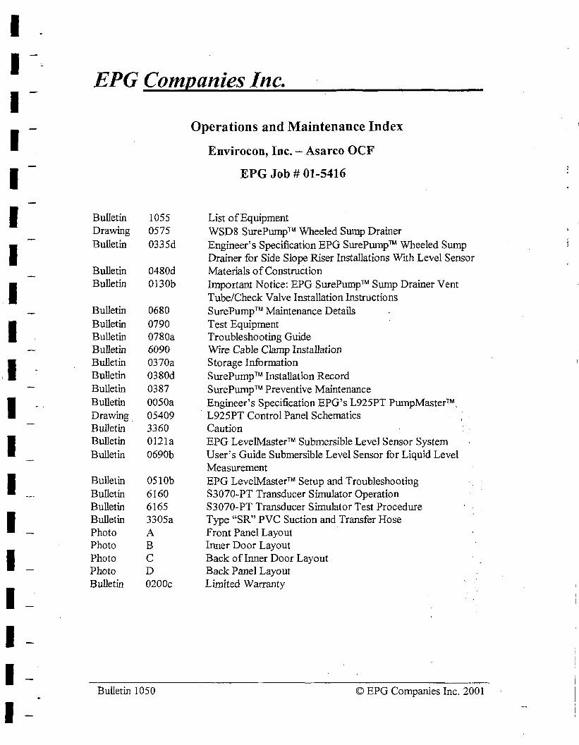
I I I I I I I I I ,I I I I I I I I I I
EPG Companies Inc.
Bulletin 1055 Drawing 0575 Bulletin 0335d
Bulletin 0480d Bulletin 0130b
Bulletin 0680 Bulletin 0790 Bulletin 0780a Bulletin 6090 Bulletin 0370a Bulletin 0380d Bulletin 0387 Bulletin 0050a Drawing 05409 Bulletin 3360 Bulletin 0121a Bulletin 0690b
Bulletin 0510b Bulletin 6160 Bulletin 6165 Bulletin 3305a Photo A Photo B Photo C Photo D Bulletin 0200c
Bulletin 1050
Operations and Maintenance Index
Envirocon, Inc. - Asarco OCF
EPG Job# 01-5416
List of Equipment WSD8 SurePump TM Wheeled Sump Drainer Engineer's Specification EPG SurePwnpTM Wheeled Sump Drainer for Side Slope Riser Installations With Level Sensor Materials of Construction Important Notice: EPG SurePumpTM Sump Drainer Vent Tube/Check Valve Installation Instructions SurePump™ Maintenance Details Test Equipment Troubleshooting Guide Wrre Cable Clamp Installation Storage Information SurePump TM Installation Record SurePumpTM Preventive Maintenance Engineer's Specification EPG's L925PT PumpMaster™. L925PT Control Panel Schematics Caution EPG LevelMaster TM Submersible Level Sensor System User's Guide Submersible Level Sensor for Liquid Level Measurement EPG LevelMaster™ Setup and Troubleshooting S3070-PT Transducer Simulator Operation S3070-PT Transducer Simulator Test Procedure Type "SR" PVC Suction and Transfer Hose Front Panel Layout Inner Door Layout Back of Inner Door Layout Back Panel Layout Limited Warranty
© EPG Companies Inc. 2001
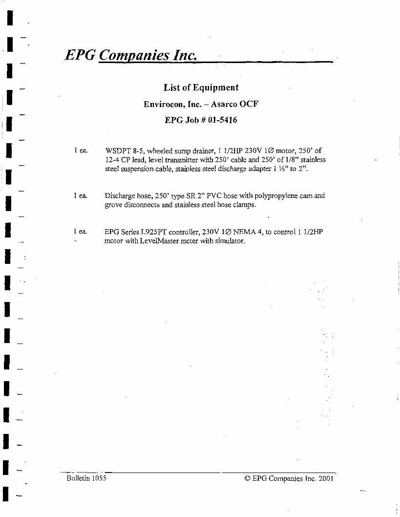
I I I I I I I I I I I I I I I I I I I
.EPG Companies Inc.
I ea.
I ea.
I ea.
List of Equipment
Envirocon, Inc. - Asarco OCF
EPG Job# 01-5416
WSDPT 8-5, wheeled sump drainer, 1 1/21-IP 230V 10 motor, 250' of 12-4 CP lead, level transmitter with 250' cable and 250' of 1/8" stainless steel suspension cable, stainless steel discharge adapter 1 ½" to 2".
Discharge hose, 250' type SR 2" PVC hose with polypropylene cam and grove disconnects and stainJess steel hose clamps.
EPG Series L925PT controller, 230V 10 NEMA 4, to control 1 1/2HP motor with LevelMaster meter with simulator.
Bulletin 1055 © EPG Companies Inc. 2001

I I I I 1: I
! I
I I I
i
..--... fw w
. L.....
0 <i w I
350
300
250
200
150
100
so
0
1 1/2"NPT
i _:PUMP MODEL
MOTOR HP
WSDB-1 a.so WSDB-2 0.75
-- WSDB-3 1.00
WSDB-4 · 1.00
WSD8-5 I.SO
- WSDB-5 1.50
WSDS-7 2.00
WSDB-8 2.00
WSD8-9 3.00
WSDB-12 5.00
WSD8
WHEt..LED
j I :;°"",I ' I ! j
I i i
i I I
j I l I
! I ! ! i
i i
! i,--__;
I ! i --..;.._: I : I I
I I ! i
SurePump TM
S U M P DR A I f\J ER
I ; I j
i :
' i
i I i j I
-----._ I
'; I I i : ! ! I 'i,.
695
! I ~-:. ! i I TSPB-i 2
!
I
I I
I a I
i I
I i i i I
I I
I I i I
10
-------
I I
,--..._: "'-I.. i'-l ' -.........., ,,:-..i... --- ' ........... ~
WSDB-3
WSDB-3
'NS08-7
WSD8-6 :,~ ,---- ;
.....,_ 'NS08-5 ............
! ; j
20 30 40 50 CAPACITY (GPM)
1------------..;B>-------------...;
SINGLE PHASE THREE PHASE SHIPPING
A (in) B (in) MOTOR HP/ A (in) ! B (in) 10 31.50 29.50 0.50 I 31.50 I 29.50 41.0
34.50 32.50 0.75 I 34.50 I 32.50 44.7
37.00 35.00 I 1.00 i 37.00 i 35.00 I 49.6
38.75 36.75 I 1.00 I 38.75 I .35.75 I 51.0'
42.25 40.25 I 1.50 i 41.25 39.25 I 59.1 I
44.00 I 42.00 I 1.50 ; 4-2. 7 5 -W.75 I 60.5
47.00 45.00 i 2.00 I 45.75 -13.75 i 65.5 I
48.75 I 46.75 I 2.00 I 47.25 ~5. 2.5 I 67.5.
58.75 56. 75 I 3.00 56.00 54.00 l 91.9 i
69.75 I 67. I 5 i 5.00 ' 53.75 01 .75 i I 15.1
◄
WEIGHT (LBS)
30 '4i.0
44.7
49.6
51.0
54.7
56.2
61.0
63.0
32.1
97.4
_ Manufacturer of Specialty Pumps, Controls and Sensors. 0575
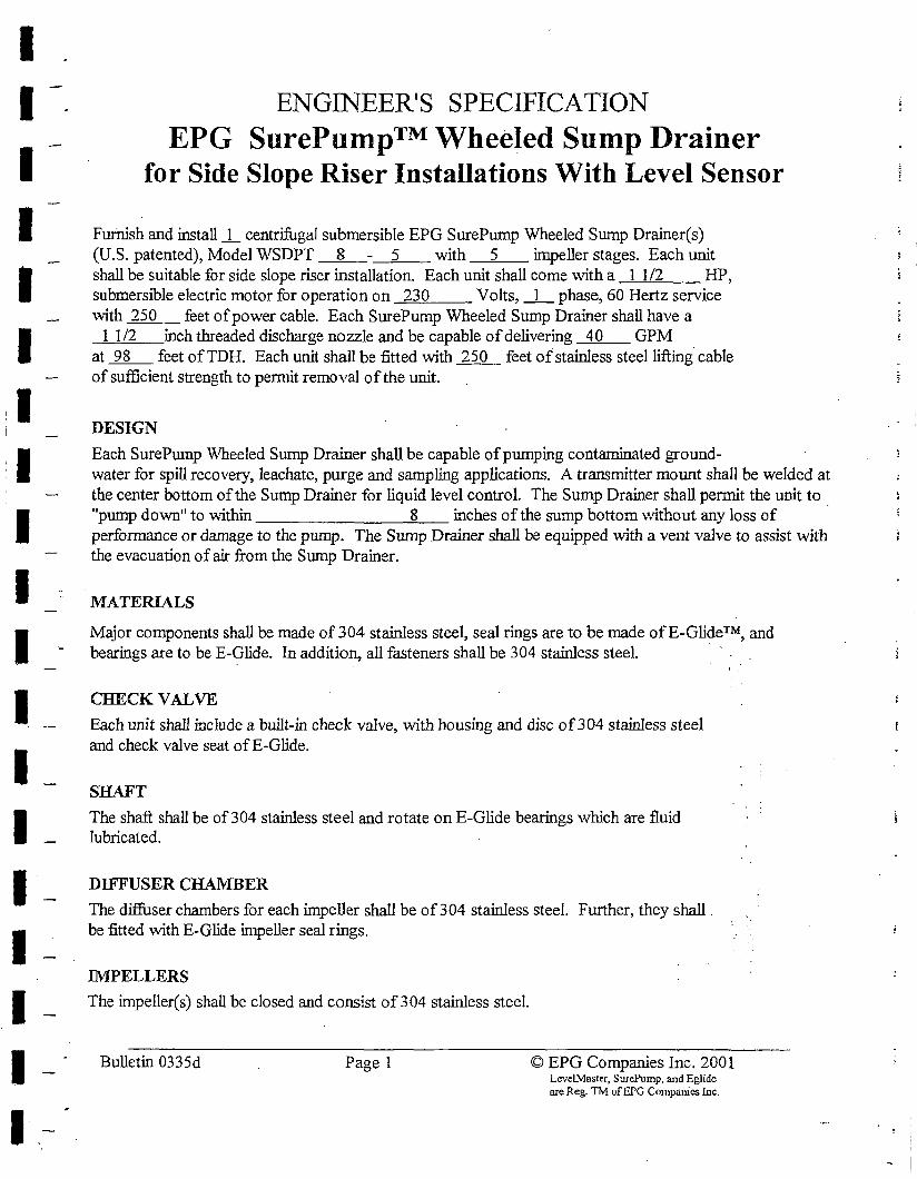
I I I I I I
I I I I I I I I I I I I
ENGINEER'S SPECIFICATION EPG SurePump™ Wheeled Sump Drainer
for Side Slope Riser Installations With Level Sensor
Furnish and install _I centrifugal submersible EPG SurePump Wheeled Sump Drainer(s) (U.S. patented), Model WSDPT 8 - 5 with 5 impeller stages. Each unit shall be suitable for side slope riser installation. Each unit shall come with a 1 1/2 HP, submersible electric motor for operation on 230 Volts, _1 _ phase, 60 Hertz service with 250 feet of power cable. Each SurePump Wheeled Sump Drainer shall have a
1 1 /2 inch threaded discharge nozzle and be capable of delivering 40 GPM at __2L_ feet of TDH. Each unit shall be fitted with _1j_Q__ feet of stainless steel liftir1g cable of sufficient strength to permit removal of the unit.
DESIGN
Each SurePump Wheeled Sump Drainer shall be capable of pumping contaminated ground-water for spill recovery, leachate, purge and sampling applications. A transmitter mount shall be welded at the center bottom of the Sump Drainer for liquid level control. The Sump Drainer shall permit the unit to "pump down" to \.\-1.thin 8 inches of the sump bottom "vithout any loss of · performance or damage to the pun1p. The Sump Drainer shall be equipped with a vent valve to assist with the evacuation of air from the Sump Drainer.
1\fATERIALS
Major components shall be made of 304 stai..TUess steel, seal rings are to be made of £-Glide™, and bearings are to be E-Glide. In addition, all fasteners shall be 304 stainless steel.
CHECK VALVE
Each unit shall include a built-in check valve, with housing and disc of 304 stainless steel and check valve seat ofE-Glide.
SHAFT The shaft shall be of 304 stainless steel and rotate on E-Glide bearings which are fluid lubricated.
DIFFUSER CHAMBER
The diffuser chambers for each impeller shall be of 304 stainless steel. Further, they shall. be fitted with E-Glide impeller seal rings.
IMPELLERS
The impeller(s) shall be closed and consist of 304 stainless steel.
Bulletin 0335d Page 1 © EPG Companies Inc. 2001 Leve!Master. SurePump, and Eglide are Reg. TM ufEPG Companies Inc.
- I
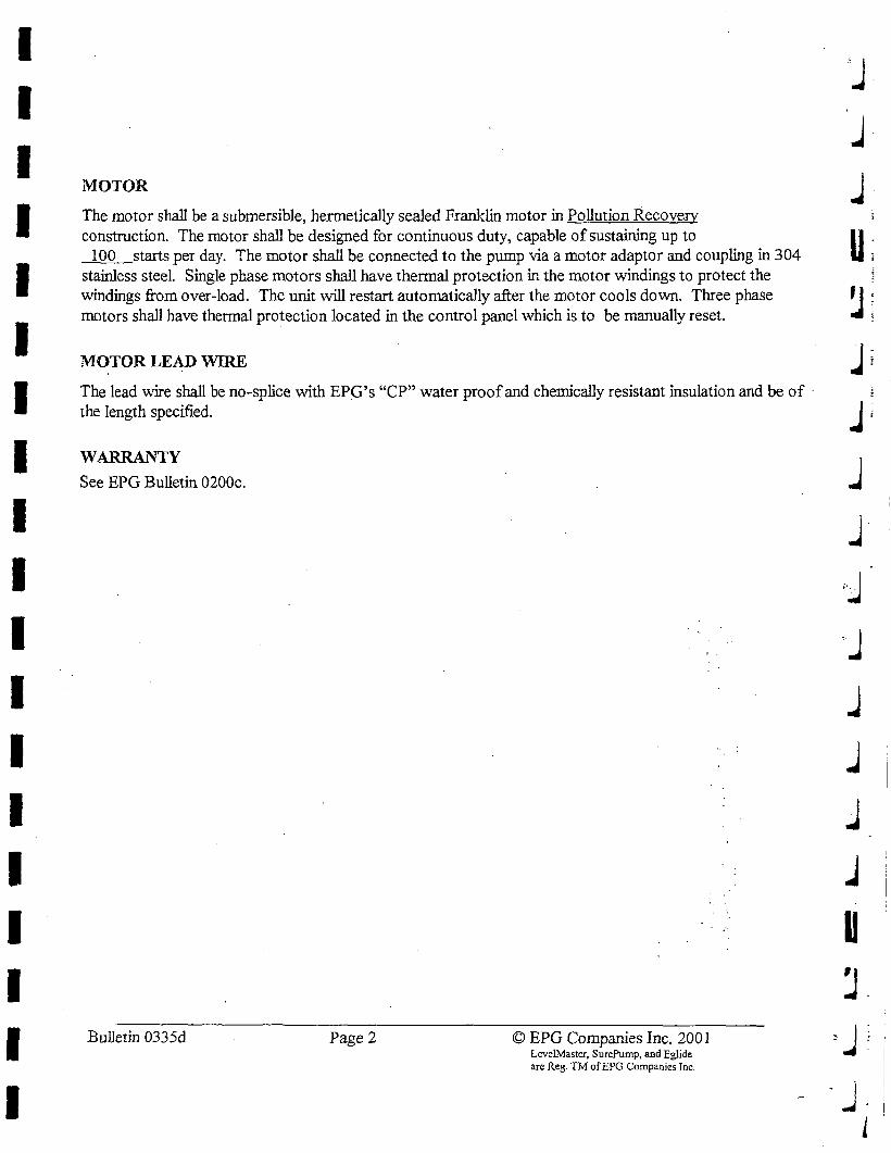
I I I I I I I I I I I I I I I I I I I
MOTOR
The motor shall be a submersible, hennetically sealed Franklin motor in Pollution Recovery construction. The motor shall be designed for continuous duty, capable of sustaining up to
100 starts per day. The motor shall be connected to the pump via a motor adaptor and coupling in 304 stainless steel. Single phase motors shall have thermal protection in the motor windings to protect the windings from over-load. The unit will restart automatically after the motor cools down. Three phase motors shall have thermal protection located in the control panel which is to be manually reset.
MOTOR LEAD WIRE
The lead v.ire shall be no-splice with EPG's "CP" water proof and chemically resistant insulation and be of · the length specified.
WARRANTY
See EPG Bulletin 0200c.
Bulletin 0335d Page2 © EPG Companies Inc. 2001 Leve!Mastcr, SurePump, and Eglide are Reg. TM ofEPG Companies Inc.
j-i
U; ~i ..Ji
l J
'J j
j
j
j
u
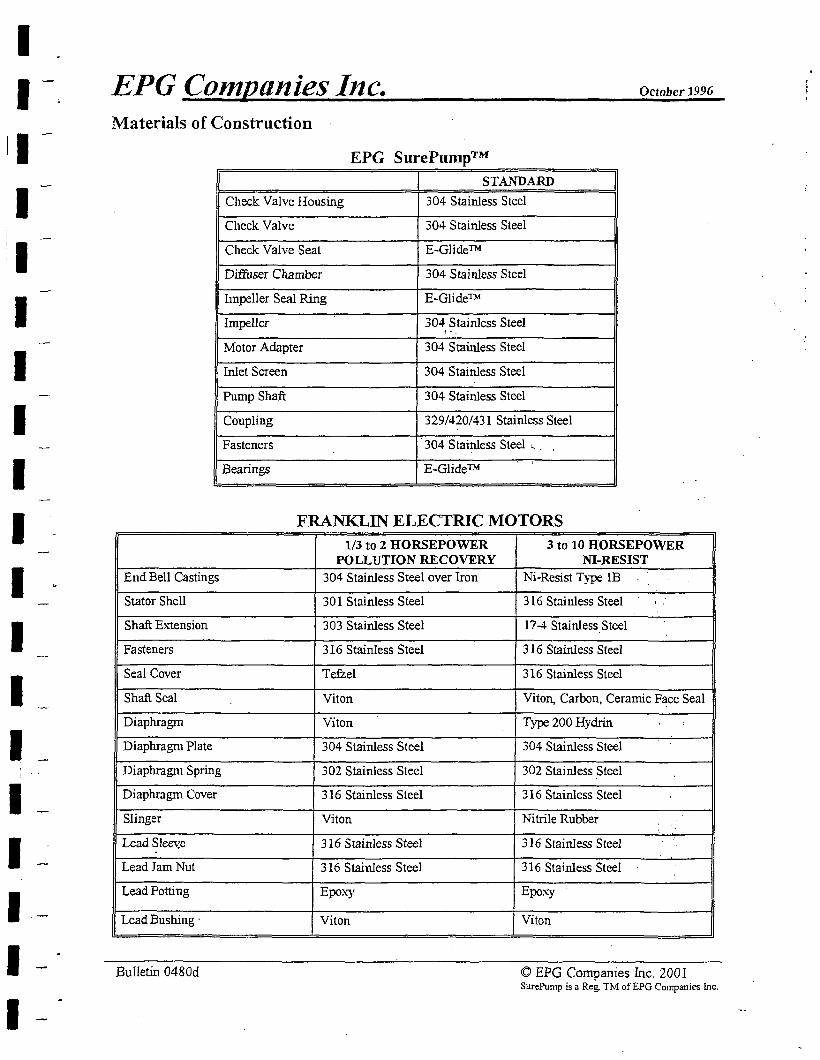
I I
I I I I I I I I I I I I I
EPG Con1pa11ies J11c. October 1996
Materials of Construction
I
End Bell Castings
Stator Shell
Shaft E:-.."tension
Fasteners
Seal Cover
Shaft Seal
Diaphragm
Diaphragm Plate
Diaphragm Spring
Diaphragm Cover
Slinger
Lead Slee\:e
Lead Jam Nut
Lead Potting
Lead Bushing ·
Bulletin 0480d
EPG SurePump™
I STANDARD I Check Valve Housing 304 Stainless Steel
Check Valve 304 Stainless Steel
Check Valve Seat E-Glide™
Diffuser Chamber 304 Stainless Steel
Impeller Seal Ring E-Glide™
Impeller 304 Stainless Steel ! ,,_
Motor Adapter 304 Stainless Steel
Inlet Screen 304 Stainless Steel
Pump Shaft 304 Stainless Steel
Coupling 329/420/431 Stainless Steel
Fasteners 304 Stainless Steel '- .
Bearings E-Glide™
FRANKLIN ELECTRIC MOTORS 1/3 to 2 HORSEPOWER 3 to 10 HORSEPOWER
POLLUTION RECOVERY 304 Stainless Steel over Iron
30 I Stainless Steel
303 Stainless Steel
316 Stainless Steel
Tefzel
Viton
Viton
304 Stainless Steel
302 Stainless Steel
316 Stainless Steel
Viton
316 Stainless Steel
316 Stainless Steel
Epo:'l.·y
Viton
NI-RESIST Ni-Resist Type lB
316 Stainless Steel '.
17-4 Stainless Steel
316 Stainless Steel
316 Stainless Steel
Viton, Carbon, Ceramic F~ce Seal
Type 200 Hydrin
304 Stainless Steel
302 Stainless Steel
316 Stainless Steel
Nitrile Rubber •.
316 Stainless Steel
316 Stainless Steel
Epoxy
Viton
© EPG Companies Inc. 2001 SurePump is a Reg. TM ofEPG Companies Inc.
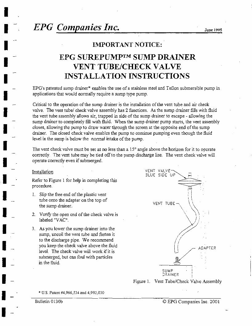
I I I I I I I I I I I I I I I I I I I -
EPG Companies Inc.
IMPORTANT NOTICE:
EPG SUREPUMP™ SUMP DRAINER VENT TUBE/CHECK VAL VE
INSTALLATION INSTRUCTIONS
June 1995
EPG's patented sump drainer* enables the use of a stainless steel and Teflon submersible pump in applications that would normally require a sump type pump.
Critical to the operation of the sump drainer is the installation of the vent tube and air check valve. The vent tube/ check valve assembly has 2 functions. As the sump drainer fills with fluid the vent tube assembly"allows air, trapped in side of the sump drainer to escape - allowing the sump drainer to completely fill with fluid. When the sump drainer pump starts, the vent assembly closes, allowing the pump to draw water through the screen at the opposite end of the sump drainer. The closed check valve enables the pump to continue pumping even though the fluid level in the sump is below the normal intake of the pump.
The vent check valve must be set at no less than a 15° angle above the horizon for it to operate correctly. The vent tube may be tied off to the pump discharge line. The vent check valve will operate correctly even if submerged.
Installation
Refer to Figure 1 for help in completing this procedure.
1. Slip the free end of the plastic vent tube onto the adapter on the top of the sump drainer.
2. Verify the open end of the check valve is labeled "VAC".
3. As you lower the sump drainer into the sump, uncoil the vent tube and fasten it to the discharge pipe. We recommend you keep the check valve above the fluid level. The check valve will work if it is submerged, but can foul with particles in the fluid.
* U.S. Patent #4,966,534 and 4,992,030
Bulletin 0130b
VENT VALVE~ 3LUE SiDE UP~
VENT TUBE-..
SUMP C;RAINER
Figure 1. Vent Tube/Check Valve Assembly
© EPG Companies Inc. 2001
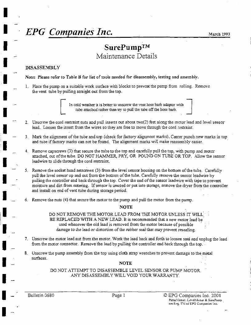
I I I I I I I I I I I I
I I I I - .
EPG Companies Inc.
DISASSEl\'IBLY
SurePump™ Niaintenance Details
Note: Please refer to Table B for list of tools needed for disassembly, testing and assembly.
March 1993
1. Place the pump on a suitable work surface with blocks to prevent the pump from rolling. Remove the vent tube by pulling straight out from the top.
[ In cold weather it is better to unscrew the vent hose barb adaptor with J
tube attached rather than try to pull the tube off the hose barb.
2. Unscrew the cord restraint nuts and pull inserts out about two(2) feet along the mcror lead and level sensor lead. Loosen the insert from the wires so they are free to move through the cord restraint.
3. Mark the alignment of the tube and top (check for factory alignment marks). Cemer punch new marks in top and tuoe if factory marks can not be found. The alignment marks will make reassembly easier. ·
4. Remove capscrews (3) that secure the tube to the top and carefully pull the top, with pump and motor attached, out of the tube. DO NOT HAMMER, PRY, OR POUND ON TUBE OR TOP. Allow the sensor leadwire to slide through the cord restraint.
5. Remove the socket head setscrews (3) from the level sensor housing on me bottom of the tube. Carefully pull the level sensor up and out from the bottom of the tube. Carefully remove the sensor leadwire by pulling the controller end back through the top. Cover the end of the sensor leadwire with tape to prevent moisture and dirt from entering. If sensor is unused or put into Storage, remove the dryer from the controller and install on end of vent tube during storage period.
6. Remove the nuts (4) that secure the motor to the pump and pull the motor from the pump.
NOTE
DO NOT REMOVE TIIE MOTOR LEAD FROM THE MOTOR UNLESS IT WILL. · BE REPLACED WITH A NEW LEAD. It is recommended that a new motor lead be.
used whenever the old lead is removed from the motor because of possible · damage to die lead or disrortion of the rubber seal that may prevent resealing.
7. Unscrew the motor lead nut from the motor. Work the lead back and forth to loosen seal and unplug the lead from the motor connector. Remove the lead by pulling the controller end back through the top ..
8. Unscrew the pump assembly from the top using cloth strap wrenches to prevent damage to the metal surfaces. · ·
NOTE
DO NOT ATTEMPT TO DISASSEMBLE LEVEL SENSOR OR PUMP MOTOR.
Bulletin 0680
Al~Y DISASSEi\tfBL Y WILL VOID YOUR WARRANTY.
Page 1 © EPG Companies Inc. 2001 Pu:np~lasta-. L<!vel!-.fosta- & SurePump are Reg. T:-! ofEPG Corr.p:ini.es Inc.
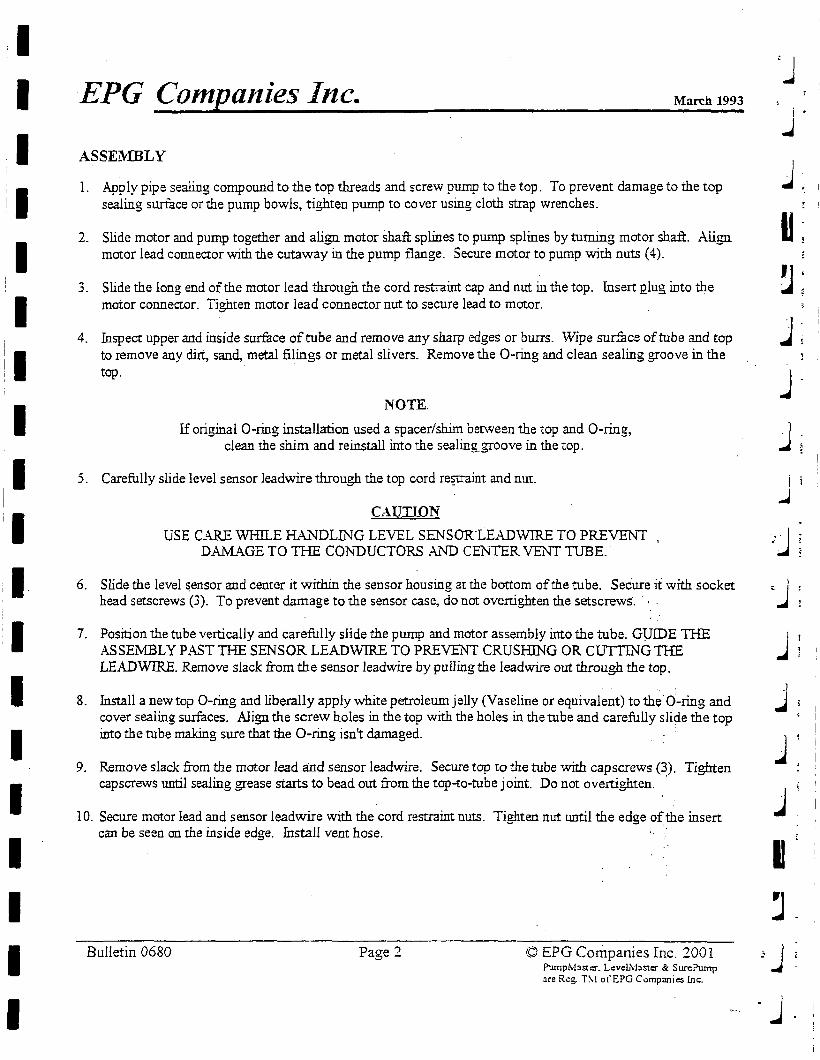
I I I
I I
I I I I
I I I I I I I
EPG Companies Inc. March 1993
ASSEMBLY
1. Apply pipe sealing compound to the top threads and screw pump to the top. To prevent damage to the top sealing surface or the pump bowls, tighten pump to cover using cloth strap wrenches.
2. Slide motor and pump together and aligu motor shaft splines to pump splines by turning motor shaft. Aligu motor lead conneetor with the cutaway in the pump flange. Secure motor to pump with nuts (4).
3. Slide the long end of the motor lead through the cord restraint cap and nut in the top. Insert Qlug into the motor connector. Tighten motor lead connector nut to secure lead to motor.
4. Inspect upper and inside surface of tube and remove any sharp edges or burrs. Wipe sur.fuce of tube and top to remove any dirt, sand, metal filings or metal slivers. Remove the O-ring and clean sealing groove in the top.
NOTE.
If original O-ring installation used a spacer/shim berween the top and O-ring, clean the shim and reinstall into the seaiing_groove in the top.
5. Carefully slide level sensor leadwire through the top cord re~a.int and mu.
CAUTION
USE CARE WHJLE HAL'l"DLING LEVEL SENSOKLEADWIRE TO PREVENT DAMAGE TO THE CONDUCTORS A.ND CENTIR VENT TUBE.
6. Slide the level ~ensor and center it within the sensor housing at the bottom of the tube. Secure it with socket head setscrews (3). To prevent damage to the sensor case, do not ovenighten the setscrews·. , .
7. Position the tube vertically and carefully slide the pump and motor assembly into the tube. GlJIDE THE ASSEMBLY PAST THE SENSOR LEADWIRE TO PREVENT CRUSHING OR CUTTING 1HE LEAD WIRE. Remove slack from the sensor leadwire by pulling the lead wire out through the top.
8. Install a new top O-ring and liberally apply white petroleum jelly (Vaseline or equivalent) to the O-ring and cover sealing surfaces. Align the screw holes in the top with the holes in the tube and carefully slide the top into the tube making sure that the O-ring isn't damaged. · ·
9. Remove slack from the motor lead a:nd sensor leadwire. Secure top to the tube with cap screws (3). Tighten capscrews until sealing grease starts to bead out from the top-to-tube joint. Do not overtighten. ·
10. Secure motor lead and sensor leadwire with the cord restraint nuts. Tighten nut until the edge of_the insert can be seen on the inside edge. Install vent hose.
Bulletin 0680 Page 2 © EPG Companies Inc. 2001 Pumplvfasier. Lc:veL\faster & SurePump ~re Rc:g. T\! ot"EPG Companies inc.
'J i
j
j '. I
~
~·
.J; I
j
j i
..J
.. -J
·J j ~ I
j
j
j
I j
:j
-J .
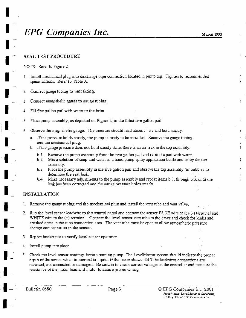
I I I I I I I I I I I I I I I I I I I
· EPG Companies Inc. March 1993
SEAL TEST PROCEDURE
NOTE: Refer to Figure 2.
I. Install mechanical plug into discharge pipe connection located in pump top. Tighten to recommended specifications. Refer to Table A.
2. Connect gauge tubing to vent fitting.
3. Connect magnehelic gauge to gauge tubing.
4. Fill five gallon pail with water to the brim.
5. Place pump assembly, as depicted on Figure 2, in the filled five gallon pail.
6. Observe the magnehelic gauge. The pressure should read about 5" wc and hold steady.
a. If the pressure holds steady, the pump is ready to be installed. Remove the gauge tubing and the mechanical plug.
b. If the gauge pressure does not bold steady state, there is an air leak in the top assembly.
b. l. Remove the pump assembly from the five gal1on pail and refill the pail with water. b.2. Mix a solution of soap and water in a hand pump spray application bottle and spray the top
assembly. . b.3. Place the pump assembly in the five gallon pail and observe the top assembly for bubbles to
determine the seal leak. b.4. Make necessary adjustments to the pump assembly and repeat items b. l. through b:3 .. until the
leak has been corrected and the gauge pressure holds steady .
JNSTALLATION
1. Remove the gauge tubing and the mechanical plug and install the vent tube and vent valve.
2. Run the level sensor leadwire to the control panel and connect the sensor BLUE wire to the (-) terminal and WHITE wire to the ( +) terminal. Connect the level sensor vem tube to the dryer and check for ·kinks and crushed areas in the tube connection area. The vent tube must be open to allow atmospheric pressure change compensation in the sensor.
3. Repeat bucket test to verify level sensor operation.
4. Install pump into place.
5. Check the level sensor readings before running pump. The Levellvfaster system should indicate-the proper depth of the sensor when immersed in liquid. If the meter shows -34. 7 the leadwires connections a:i:-e reversed, not connected or damaged. Be certain to check correct voltages at the controller and measure the resistance of the motor lead and motor to assure proper wiring.
Bulletin 0680 Page 3 © EPG Companies Inc. 200 I Pump,\.faSler. L~v~l!vlaste:r & SurePump :ire Reg. Thi ofEPG C.:>mpanies lnc.
• I
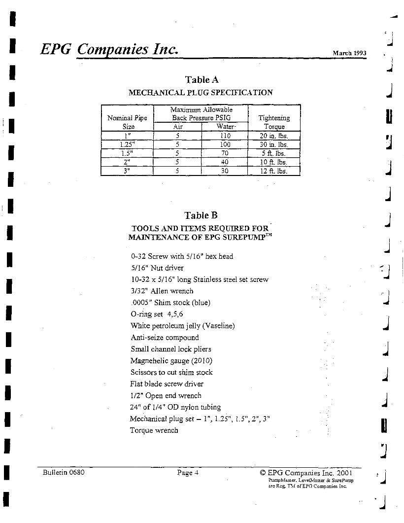
I I I I I I I I I I I I I I I I I I I
EPG Companies Inc. Marcil 1993
Bulletin 0680
Table A MECHANICAL PLUG SPECJFICA. TION
Maximum Allowable Nominal Pipe Back Pressure PSIG Tightening
Size Air Water- Toroue l" 5 110 20 in. lbs.
1.25" 5 100 30 in. lbs. 1.5" 5 70 5 ft. lbs. 2" 5 40 10 ft. lbs. 3" 5 30 12 ft. lbs.
TableB TOOLS AND ITEMS REQU1R.ED FOR
MAJNTENAL~CE OF EPG SUREPUl\'IPrn
0-32 Screw with 5/16" hex head
5/1611 Nut driver
10-32 x 5/16" long Stainless steel set screw
3/32" Allen wrench
.0005" Shim stock (blue)
O-ring set 4,5,6
White petroleum jelly (Vaseline)
Anti-seize compound
Small channel lock pliers
Magnehelic gauge (2010)
Scissors to cut shim stock
Flat blade screw driver
1/2" Open end wrench
24" of 1/4" OD nylon tubing
Mechanical plug set - I", 1.25", I.5", 2", 3"
Torque wrench
Page -4 © EPG Companies Inc. 2001 PumpMasu::r. Levc:l.lvlaster & Sw-ePump are Reg. Thi ofEPG Comp:inies !nc.
l .J
j
u J ]
j
j
J ~J .-J
J j
j
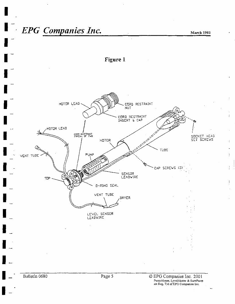
I I I I I I I I I I I I I I I I I I I
EPG Companies Inc. March 1993
Figure 1
MOTOR LEAD ~~I 'CORD RESTRA1NT \ ' NUT ,
1 CORD RESiRAINT
: ·= . ',,!~ MOTOR LEAD
VENT TUBE
Bulletin 0680
□-RING SE.4L
INSERT E. CAP
SENSOR LE,O,D\i/iRE
VENT TUBE
~DRYER
LEVEL SENSOR LEADVIRE
Page 5
' af II' J
-1/ ,,/' SOCKET ~E~D , SET SCREWS
(3) ·.
© EPG Companies Inc. 200 I ?ump/vf:ister, Level.Master & SurePump m: Reg. TM ofEPG Companies lnc.
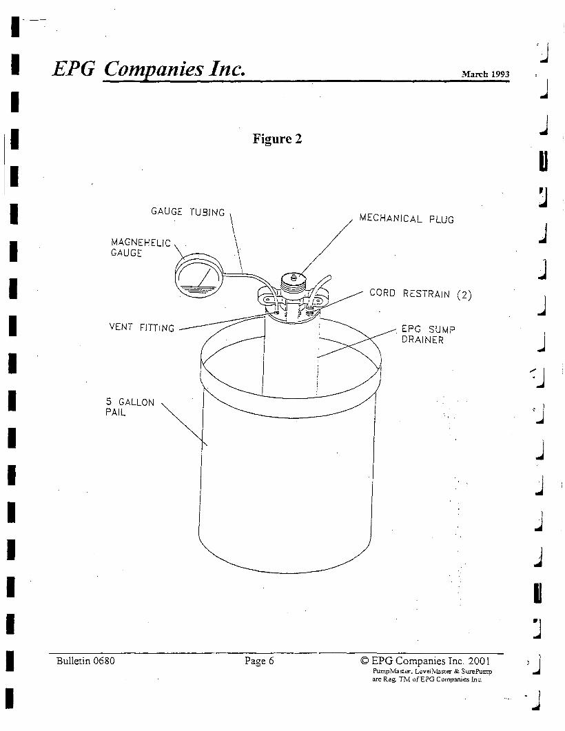
1--
I EPG Companies Inc. 'j
March 1993
j I I Figure 2
j
I u :J
: I GAUGE TUSING \
/ MECHANICAL PLUG
] \ MAGNEHELIC I
I GAUGE \· . \ /
j \
I 9· ~
. I ,,-....._, CORD RESTRAIN (2) ';,~ j .. .__.-.-
I VENT FITTING EFG SUMP
j DRAINER
I ~ J I 5 GALLON ~j PAIL
I j I j
I °I
..J
I j
I m
I J I Bulletin 0680 Page 6 © EPG Companies Inc. 200 l 1J J>umplvlaster. Lcveilv!aster & SurePump
are Reg. TM ofEPG Companies Inc.
I ·-- . j
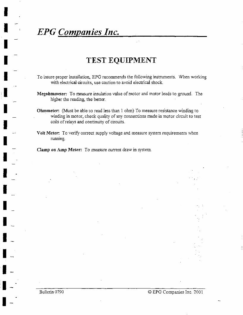
I I I I
I I I I I I I I I I I I I
EPG Companies Inc.
TEST EQUIPMENT
To insure proper installation, EPG recommends the following instruments. When working with electrical circuits, use caution to avoid electrical shock.
Megohmmeter: To measure insulation value of motor and motor leads to ground. The higher the reading, the better.
Ohmmeter: (Must be able to read less than I ohm) To measure resistance winding to winding in motor, check quality of any connections made in motor circuit to test coils of relays and continuity of circuits.
Volt Meter: To verify correct supply voltage and measure system requirements when running.
Clamp on Amp Meter: To measure current draw in system.
Bulletin 0790 © EPG Companies Inc. 200 I
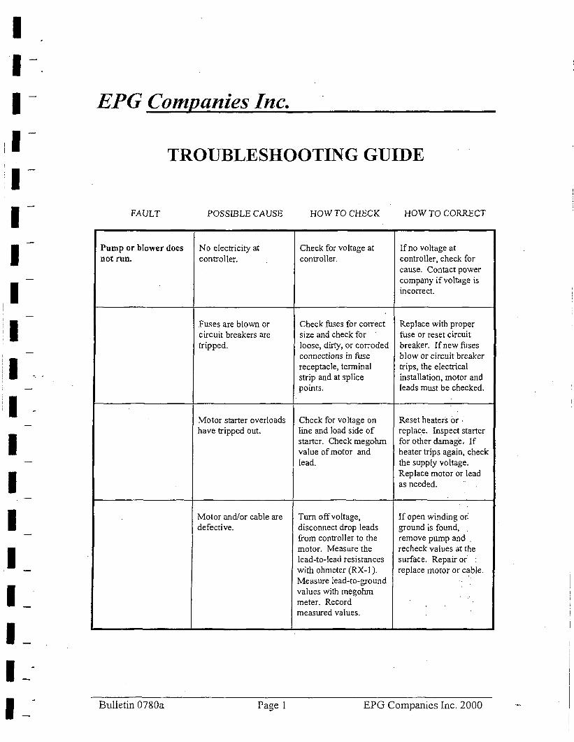
I I I I I I I I I I I I I I I I I I I
EPG Companies Inc.
TROUBLESHOOTING GUIDE
FAULT POSSIBLE CAUSE HOWTOCHECK HOW TO CORRECT
Pump or blower does No electricity at Check for voltage at Ifno voltage at not run. controller. controller. controller, check for
cause. Contact power company if voltage is incorrect.
Fuses are blown or Check fuses for correct Replace with proper circuit breakers are size and check for fuse or reset circuit tripped. loose, dirty, or corroded breaker. If new fuses
connections in fuse blow or circuit breaker receptacle, terminal trips, the electrical strip and at splice installation, motor and points. leads must be checked.
Motor starter overloads Check for voltage on Reset heaters or · have tripped out. line and load side of replace. Inspect starter
starter. Check megohm for other damage, If value of motor and heater trips again, check lead. the supply voltage,
Replace motor or lead as needed.
..
Motor and/or cable are Turn off voltage, If open winding or: defective. disconnect drop leads ground is found,
from controller to the remove pump and . motor. Measure the recheck values at the lead-to-lead resistances surface. Repair or with ohrneter (RX-I). replace motor or c~ble. Measure lead-to-ground values with megohm meter. Record measured values.
Bulletin 0780a Page 1 EPG Companies Inc. 2000
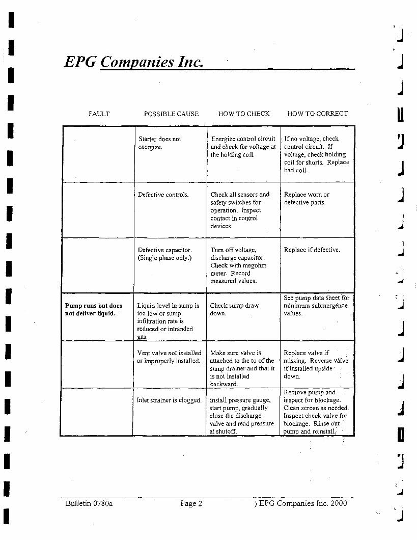
I I I I I I I I I I I I I I I I I I I
EPG Companies Inc.
FAULT POSSIBLE CAUSE
Starter does not energize.
Defective controls.
Defective capacitor. (Single phase only.)
Pump runs but does Liquid level in swnp is not deliver liquid. too low or sump
infiltration rate is reduced or intranded gas.
Vent valve not installed or improperly installed.
Inlet strainer is clogged.
Bulletin 0780a Page 2
HOW TO CHECK HOW TO CORRECT
Energize control circuit lfno voltage, check and check for voltage at control circuit. ff the holding coil. voltage, check holding
coil for shorts. Replace bad coil.
Check all sensors and Replace worn or safety switches for defective parts. operation. Inspect contact in control devices.
Turn off voltage, Replace if defective. discharge capacitor. Check with megohm meter. Record measured values.
See pump data sheet for Check sump draw minimwn submergence down. values.
Make sure valve is Replace valve if attached to the to of the missing. Reverse valve swnp drainer and that it if installed upside · is not installed down. backward.
Remove pump and Install pressure gauge, inspect for blockage. start pump, gradually Clean screen as needed. close the discharge Inspect check valve for valve and read pressure blockage. Rinse out· at shutoff. pump and reinstall.·
) EPG Companies Inc. 2000
J j
u J j
J j
J
j
j
j
.J
u J
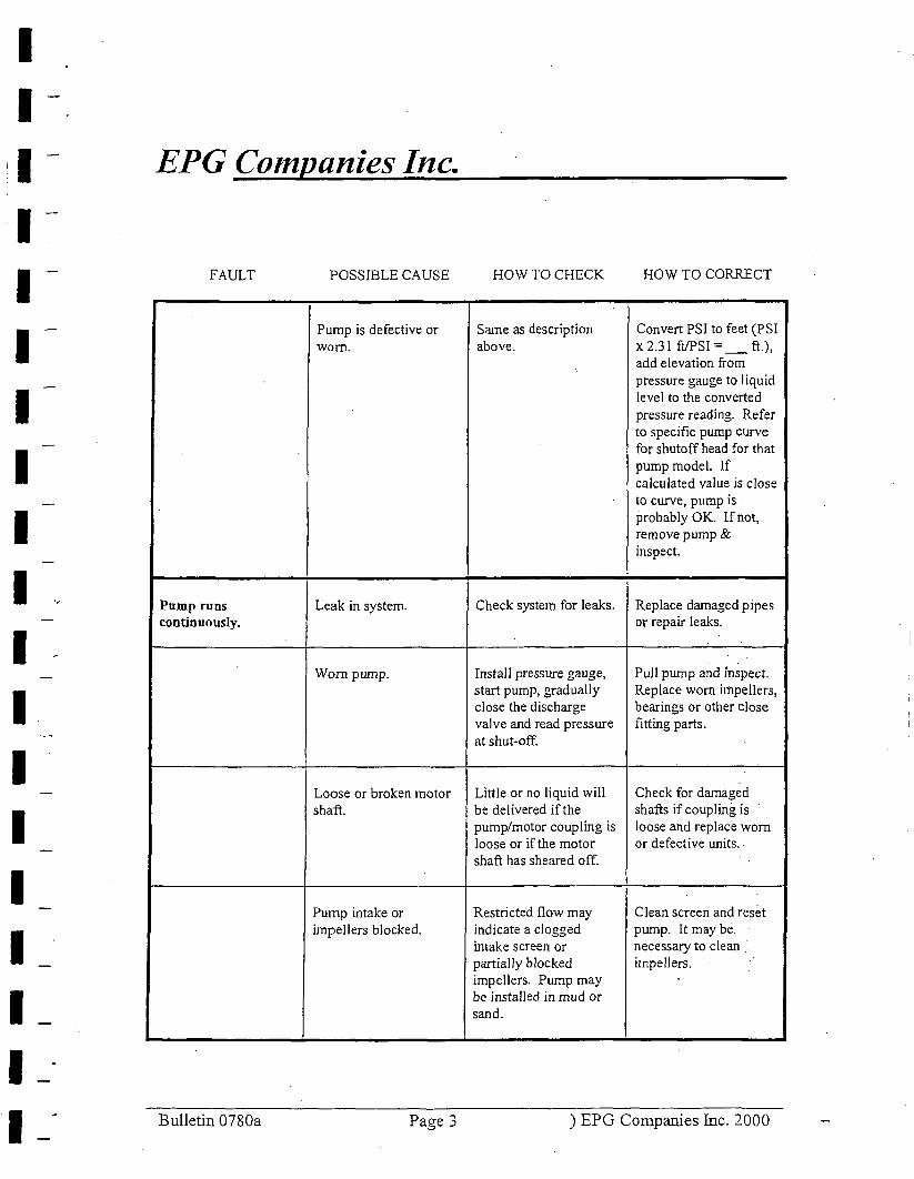
I I I I I I
I I I I I I I I I I I
EPG Companies Inc.
FAULT POSSIBLE CAUSE
Pump is defective or worn.
Pump runs Leak in system. continuously.
Worn pump.
Loose or broken motor shaft.
Pump intake or impellers blocked.
Bulletin 0780a Page 3
HOW TO CHECK HOW TO CORRECT
Sa.me as description Convert PSI to feet (PSI above. x 2.31 ft/PSI= _ft.),
add elevation from pressure gauge to liquid level to the converted pressure reading. Refer to specific pump curve for shutoff head for that pump model. If calculated value is close to curve, pump is probably OK. Ifnot, remove pump & inspect.
Check system for leaks. Replace damaged pipes or repair leaks.
Install pressure gauge, Pull pump and inspect. start pump, gradually Replace worn impellers, close the discharge bearings or other tlose valve and read pressure fitting parts. at shut-off.
Little or no liquid will Check for damaged be delivered if the shafts if coupling i$ pump/motor coupling is loose and replace worn loose or if the motor or defective units .. shaft has sheared off.
Restricted flow may Clean screen and reset indicate a clogged pump. It may be. intake screen or necessary to clean . partially blocked impellers. impellers. Pump may be installed in mud or sand.
) EPG Companies Inc. 2000
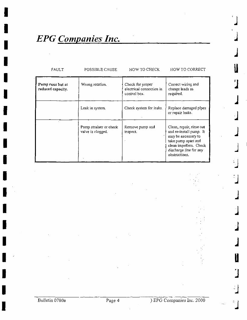
I I I I I I I I I I I I I I I I I I I
EPG Companies Inc.
FAULT POSSIBLE CAUSE
Pump runs but at Wrong rotation. reduced capacity.
Leak in system.
Pump strainer or check valve is clogged.
BulJetin 0780a Page4
HOW TO CHECK HOW TO CORRECT
Check for proper Correct wiring and electrical connection in change leads as control box. required.
Check system for leaks. Replace damaged pipes or repair leaks.
Remove pump and Clean, repair, rinse out inspect. and re-install pump. It
may be necessary to take pump apart and clean impellers. Check discharge line for any obstructions.
) EPG Companies Inc. 2000
j
.J
u
j
J J
J j
j
J u ]
·J
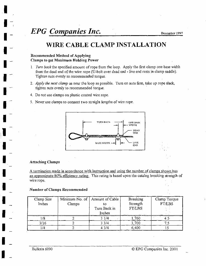
I I I I I I I I I I I I I I I I I I
EPG Compa11ies Inc. December 1997
WIRE CABLE CLAMP INSTALLATION
Recommended Method of Applying Clamps to get Maximum Holding Power
l. Tum back the specified amount of rope from the loop. Apply the first clamp one base width from the dead end of the wire rope (U-bolt over dead end - live end rests in clamp saddle). Tighten nuts evenly to recommended torque.
2. Apply the next clamp as near the loop as possible. Turn on nuts firm, talce up rope slack, tighten nuts evenly to recommended torque.
4. Do not use clamps on plastic coated wire rope.
5. Never use clamps to connect two straight lengths of wire rope.
TURN B,\CK
Attaching Oamps
DNEBASE WIDTI{
DEAD "END
LJVE END
A termination made in accordance with instruction and using the number of clamps shown has an approximate 80% efficiencv rating. This rating is based upon the catalog breaking strength of Wife rope.
Number of Clamps Recommended
Clamp Size Minimum No. of Amount of Cable Breaking Clamp Torque Inches Clamps to Strength FT/LBS
Turn Back in FT/LBS Inches
1/8 2 3 1/4 1,760 4_5. 3/16 2 3 3/4 3,700 7.5 1/4 2 4 3/4 6,400 15
Bulletin 6090 © EPG Companies Inc. 2001
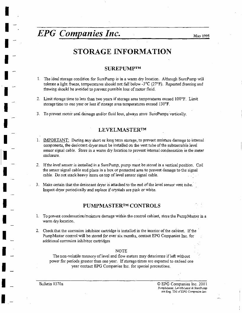
I I I I I I I I I I I I I I I I I I I
EPG Companies Inc. May 1995
STORAGE INFORMATION
SUREPUMP™
1. The ideal storage condition for SurePump is in a warm dry location. Although SurePump will tolerate a light freeze, temperatures should not fall below -3°C (27°F). Repeated freezing and thawing sbou]d be avoided to prevent possible loss of motor fluid.
2. Limit storage time to less than two years if storage area temperatures exceed 100°F. Limit storage time to one year or less if storage area temperatures exceed 130°F.
3. To prevent motor seal damage and/or fluid loss, always store Sui-ePumps vertical1y.
LEVELMASTER™
1. IMPORT ANT: During any short or long term storage, to prevent moisture damage to internal components, the desiccant dryer must be installed on the vent tube of the submersible level sensor signal cable. Store in a warm dry location to prevent internal condensation in the meter enclosure.
2. If the level sensor is installed in a SurePump, pump must be stored in a vertical position. Coil the sensor signal cable and place in a box or protected area to prevent damage to the signal cable. Do not stack heavy items on top of !eve] sensor signal cable.
3. Make certain that the desiccant dryer is attached to the end of the level sensor vent tube. Inspect dryer periodically and replace if crystals are pink or white.
PUl\!IPMASTER™ CONTROLS
1. To prevent condensation/moisture damage within the control cabinet, store the Pump Master in a warm dry location.
2. Check that the corrosion inhibitor cartridge is installed in the interior of the cabinet. If the · PumpMaster control will be stored for over six months, contact EPG Companies Inc. for additional corrosion inhibitor cartridges
NOTE The non-volatile memory of level and flow meters may deteriorate if left without
power for periods greater than one year. If storage times are expected to exceed one year contact EPG Companies Inc. for special precautions.
Bulletin 0370a © EPG Companies Inc. 2001 Pump1'faster. Level Master & SurePump
are Reg. TM ofEPG Companies Inc.
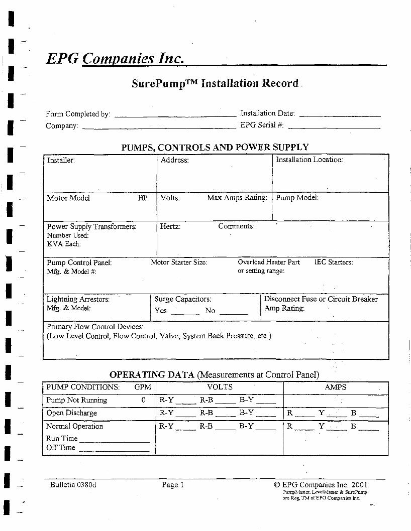
I I I I I ·I I I I I I -1 I I I I I I I
EPG Companies Inc.
SurePump™ Installation Record.
Form Completed by: _____________ Installation Date: ________ _
Company: EPG Serial #: _________ _
PUMPS, CONTROLS AND POWER SUPPLY Installer: Address: Installation Location:
Motor Model HP Volts: Max Amps Rating: Pump Model:
Power Supply Transformers: Hertz: Comments: Number Used: KVAEach:
Pump Control Panel: Motor Starter Size: Overload Heater Part IEC Starters: Mfg. & Model #: or setting range:
Lightning Arrestors: Surge Capacitors: Disconnect Fuse or Circuit Breaker Mfg. & Model: Yes No Amp Rating:
Primary Flow Control Devices: (Low Level Control, Flow Control, Valve, System Back Pressure, etc.)
OPERA TING DAT A (Measurements at Control Panel) PU1\1P CONDITIONS: GPM VOLTS
Pump Not Running 0 R-Y R-B B-Y
Open Discharge R-Y R-B B-Y --Normal Operation R-Y R-B B-Y
Run Time Off Time
Bulletin 0380d Page 1
AMPS
--R y B -- -- --R y B -- -- --
© EPG Companies Inc. 200 l Pump!v!aster. Level!v!aste:r & SurePump 3re Reg. TM ofEPG Companies Inc.
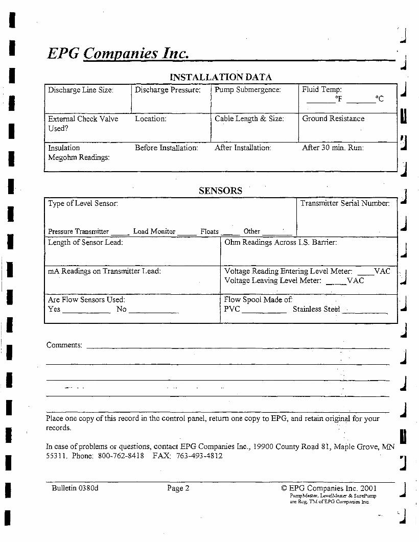
I I I I I I I I
I I
I I I I I
EPG Companies Inc. INSTALLATION DATA
Discharge Line Size: Discharge Pressure: Pump Submergence: Fluid Temp: Of oc
External Check Valve Location: Cable Length & Size: Ground Resistance Used?
Insulation Before Installation: After Installation: After 3 0 min. Run: Megohm Readings:
SENSORS -Type of Level Sensor: Transmitter Serial Number:
Pressure Transmitter Load Monitor Floats Other
Length of Sensor Lead: Ohm Readings Across I. S. Barrier:
mA Readings on Transmitter Lead: Voltage Reading Entering Level Meter: VAC --Voltage Leaving Level Meter: __ V AC
Are Flow Sensors Used: Flow Spool Made of: Yes No PVC Stainless Steel
Comments: ---------------------------------
Place one copy of this record in the control panel, return one copy to EPG, and retain original for your records.
In case of problems or questions, contact EPG Companies Inc., 19900 County Ro~d Si, Maple Grove, MN 55311. Phone: 800-762-8418 FAX: 763-493-4812
Bulletin 0380d Page 2 © EPG Companies Inc. 2001 PumpMaste:r. Levell\faste:r & SurePump are Reg. nl ofEPG Companies Inc.
j
..J
u
j
j
j
J j
..l
.J u J J j
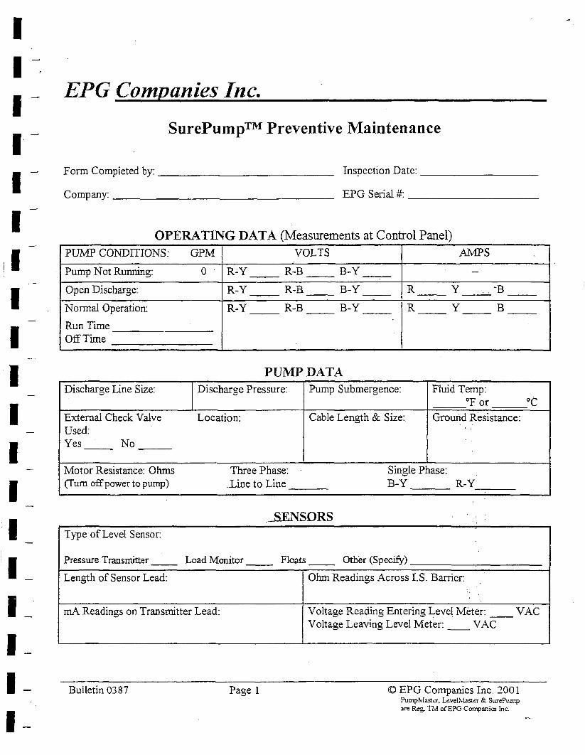
I I I I I I
I I
I I I I
EPG Companies Inc.
SurePump™ Preventive Maintenance
Form Completed by:_____________ Inspection Date: ________ _
Company: _________________ EPG Serial#: _________ _
OPERA TING DAT A (Measurements at Control Panel) PU1v1P CONDITIONS: GPM VOLTS AMPS
Pump Nat Running: 0 R;.Y R-B B-Y ---- --Open Discharge: R-Y R-B B-Y R y . -B -- -- --Normal Operation: R-Y R-B B-Y R y B -- -- -- --Run Time Off Time
PUMP DATA Discharge Line Size: Discharge Pressure: Pump Submergence: Fluid Temp:
°For ot External Check Valve Location: Cable Length & Size: Ground Resistance: Used: ' .
Yes No --
Motor Resistance: Ohms Three Phase: Single Phase: (Tum off power to pump) .Line to Line B-Y R-Y
.. -8ENSORS Type of Level Sensor:
Pressure Transmitter -- Load Monitor -- Floats -- Other (Specify)
Length of Sensor Lead: Ohm Readings Across LS. Barrier:
mA Readings on Transmitter Lead: Voltage Reading Entering ~eve! Meter: __ V AC
Bulletin 0387 Page 1
Voltage Leaving Level Meter: __ V AC
© EPG Companies Inc. 2001 PumpMastcr. Levell'v!aster & SurePump :ire R,:g. Th! ofEPG Companies Inc.
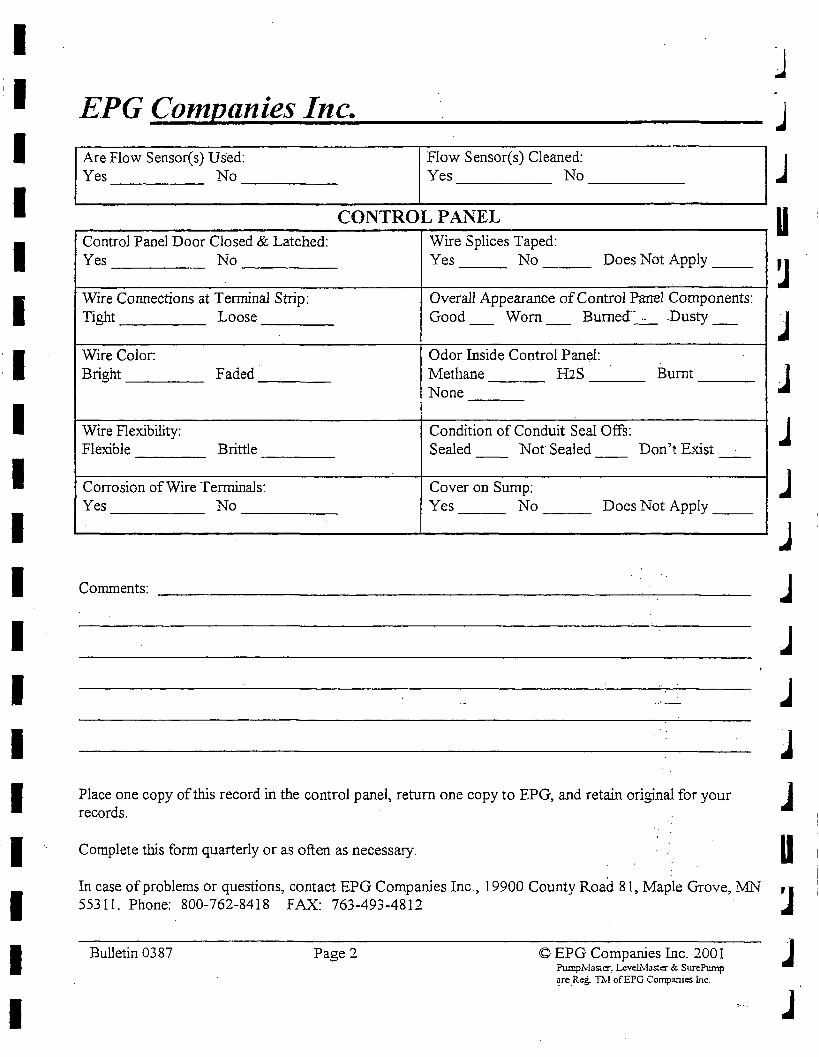
I
I I I I I I I I I I I I I , I
I I I
EPG Companies Inc.
Are Flow Sensor(s) Used: Flow Sensor(s) Cleaned: Yes _____ No _____ _ Yes _____ No _____ _
CONTROL PANEL Control Panel Door Closed & Latched: Wire Splices Taped: Yes No Yes No Does Not Apply
Wire Connections at Terminal Strip: Overall Appearance of Control Panel Components: Tight Loose Good Worn Burned-~ -Dusty _ - -
Wire Color: Odor Inside Control Panel: Bright Faded Methane IDS Burnt
None
Wire Flexibility: Condition of Conduit Seal Offs: Flexible Brittle Sealed Not Sealed Don't Exist -- -- --
Corrosion of Wire Tenninals: Cover on Sump: Yes No Yes No Does Not Apply __
Comments:
j
j
j
u
J J J .J j
J J J J
Place one copy of this record in the control panel, return one copy to EPG, and retain original for your J records.
Complete this form quarterly or as often as necessary. U In case of problems or questions, contact EPG Companies Inc., 19900 County Road 81, Maple Grove, MN 'I 55311. Phone: 800-762-8418 FAX: 763-493-4812 ..
Bulletin 0387 Page 2 © EPG Companies Inc. 2001 PumpMaster, Leveli\laster & SurePwnp ~re_R.:g. Thi ofEPG Companies Inc.
J J
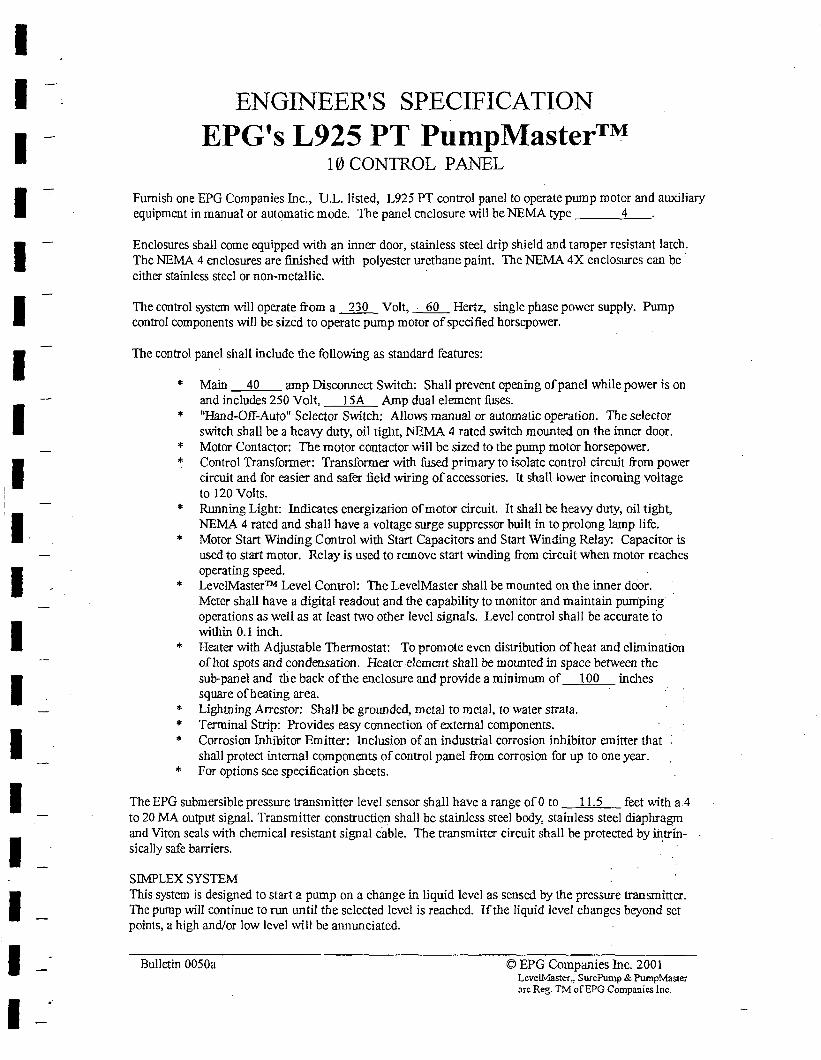
I I I I I I I I
I I I I I I I I I
ENGINEER'S SPECIFICATION
EPG's L925 PT PumpMaster™ 10 CONTROL PANEL
Furnish one EPG Companies Inc., U.L. listed, L925 PT control panel to operate pillDp motor and auxiliary equipment in manual or automatic mode. The panel enclosure will be NEMA type 4
Enclosures shall come equipped with an inner door, stainless steel drip shield and tamper resistant latch. The NEMA 4 enclosures are finished with polyester urethane paint. The NEMA 4X enclosures can be· either stainless steel or non-metallic.
The control system \Vill operate from a 230 Volt, __:___QQ___ Hertz, single phase power supply. Pump control components will be sized to operate pump motor of specified horsepower.
The control panel shall include the following as standard features:
* Main 40 amp Disconnect Switch: Shall prevent opening of panel while power is on and includes 250 Volt, 15A Amp dual element fuses.
* "Hand-Off~Auto" Selector Switch: Allows manual or automatic operation. The selector switch shall be a heavy duty, oil tight, l\1EMA 4 rated switch mounted on the inner door.
* Motor Contactor: The motor contactor will be sized to the pump motor horsepower. * Control Transformer: Transformer with fused primary to isolate control circuit from power
circuit and for easier and safer field wiring of accessories. It shall lower incoming voltage to 120 Volts.
*
*
*
* *
Running Light: Indicates energization of motor circuit. It shall be heavy duty, oil tight, NEMA 4 rated and shall have a voltage surge suppressor built in to prolong lamp life. Motor Start Winding Control with Start Capacitors and Start Winding Relay: Capacitor is used to start motor. Relay is used to remove start winding from circuit when motor reaches operating speed. Leve!Master™ Level Control: The LevelMaster shall be mounted on the inner door .. Meter shall have a digital readout and the capability to monitor and maintain purriping operations as well as at least two other level signals. Level control shall be accurate to within 0.1 inch. Heater with Adjustable Thermostat: To promote even distribution of heat and elimination of hot spots and condensation. Heater element shall be mounted in space between the sub-panel and the back of the enclosure and provide a minirnwn of 100 inches square of heating area. Lightning Arrestor: Shall be grounded, metal to metal, to water strata. Terminal Strip: Provides easy connection of external components. Corrosion Inhibitor Emitter: Inclusion ofan industrial corrosion inhibitor emitter that shall protect internal components of control panel from corrosion for up to one year. for options see specification sheets.
The EPG submersible pressure transmitter level sensor shall have a range ofO to 11.5 feet with a4 to 20 MA output signal. Transmitter construction shall be stainless steel body, stainless steel diaphragm and Viton seals with chemical resistant signal cable. The transmitter circuit shall be protected by intrin-sically safe barriers. ·
SIMPLEX SYSTEM This system is designed to start a pump on a change in liquid level as sensed by the pressure transmitter. The pump will continue to run until the selected level is reached. If the liquid level changes beyond set points, a high and/or low level will be annunciated.
Bulletin 0050a © EPG Companies Inc. 2001 Lcve!Master., SurePump & PumpMaster arc Reg. TM ofEPG Companies Inc.
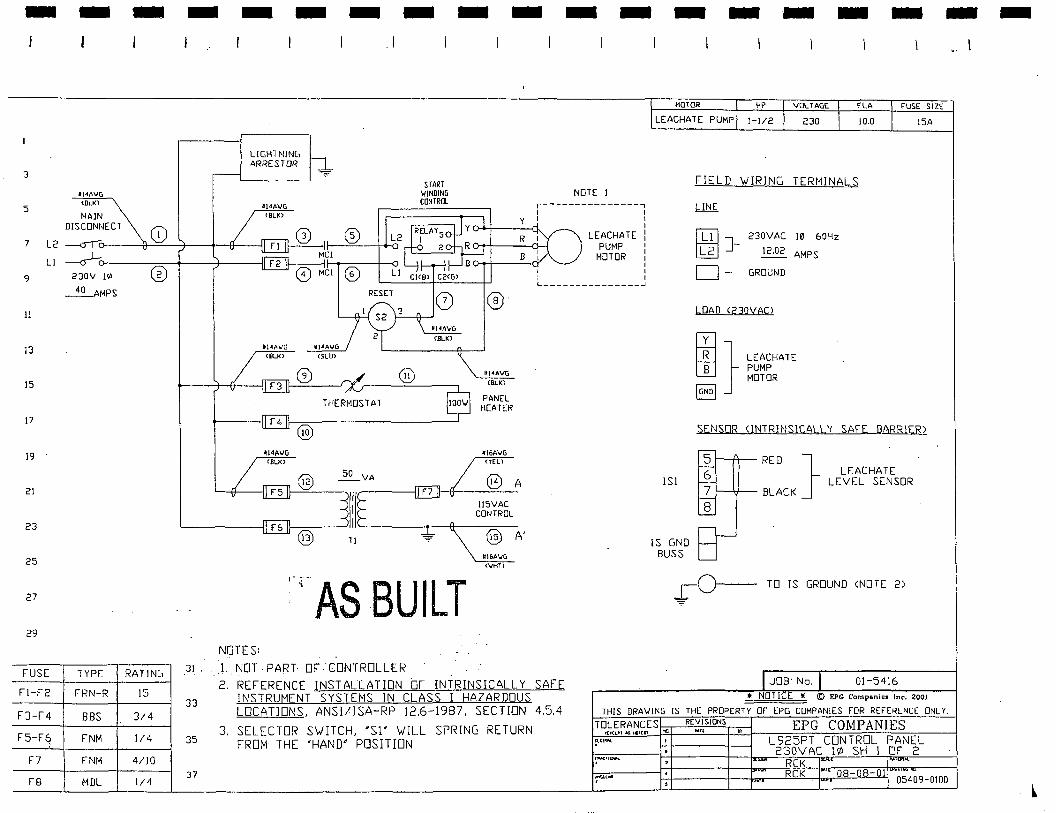
-
3
5
7 L2
LI
9
II
13
15
17
19
21
23
25
27
29
FUSE
Fl-F2
FJ-F4
F5-F6 ;
F7
FB
- - -
114A\lG
- -LIGHTMJNG ARRESTOR
- - - - -.1
NOTE I
- - - - - -HOlOR 1-<P VOL lAGE FUSE SIZE
LEACHATE PUMP 1-112 230 10.0 !SA
FIELD \./IRING TERMINALS
<BLKl
NAJN DISCDNl~ECT
0 ----<J7c ------tt---+---.· ~? 1---®=s -~ ~Cl
START 1/INDING CONTROL r---------------7
I I y I I
{.)-4-+----,:J.. LEACHATE i PUMP 1
.l.l.t!E;_
lc~I J-230VAC !~ 60Hz
12.02 AMPS -a-½ 0
-----+----+-----l F2 f--.----+---o 0 MCI©
MOTOR : I
□ -230V 1111
~AMPS
TYPE RATING
FRN-R 15
BBS 314
FNM 1/4
FNM 4/10
MDL 1/4
RESET
ll<IAVG CEILK>
® lt14A\rtG
<BLK)
THERMOSTAT PANEL HEATER
F4
® ~l4AVG 1!16AIIG
CBLIO <YEU
@ llSVAC
CONTROL
® Ul6A\/G (\JHl)
:·•As BUILT NOTES:
I I I I ~---------------J
A
A'
ISi
IS GND BUSS
GROUND
LOAD (230VACl
LEACHATE PUMP MOTOR
SENSOR <INTRlNSlCAll Y SAFE BARRIER)
~ RED }
7 t---'d--- BLACK
8
LEACHATE LEVEL SENSOR
TO IS GROUND <NOTE 2)
31 .. ). _.NOT· PART- OF". CONTROLL-ER
JJ
35
37
2. REFERENCE JNSTALLATI□N b, INTRINSICALLY SAFE INSTRUMENT SYSTEMS IN CLASS I HAZARDOUS LOCATIONS, ANSI/ISA-RP 12.6-1987, SECTI□N 4.5.4
3. SELECTOR S\./ITCH, 'Sl' \./ILL SPRING RETURN FROM THE 'HAND" POSITION
J□ B· No. 01-5416
* NOT ICE !l © EPG Companie• Inc, 2001
THIS DRA\/ING IS THE PROPERTY OF EPG COMPANIES FOR REFERENCE □NL Y.
TO~~c~!t~,f ,,ES ,.,_ RE~,~SIONS EPG COMPANIES
-
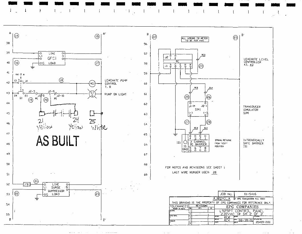
-A
38
39
40
41
42
43
44
45
46
47
48
49
50
51
54
55
B
@
@
- .. - -
L[NE
GFCI N
G LOAD
AS BUILT
-®
- -A'
LEACHATE PUMP CONTROL 7, 8
PUMP ON LIGHT
B'
- -B
@ 56
57
58
59
60
61
62
63
64
65
66
67
68
69
-
J2 I 2
JI
- -
Ml
lSl
ALL \./IRING TO METER TO BE ij22 AVG
RED
JI-M J2-l SIMI
(+) (-)
RCD OLK
2 CHANNEL DC BARRIER
G1J0 5678
0 0 0 0
- -
SPRING RETURrlE
FROM 'lEST' POSirlON
@
- -B'
LEACHATE LEVEL CONTROLLER 43, 43
TRANSDUCER SIMULATOR SIMI
JNTR!NSICALL Y SAFE BARRIER !SI
FOR NOTES AND REVISIONS SEE SHEET I
LAST WIRE NUMBER USED: 28
JOB No. 01-5416
"' NOTIC ll © EPG Compon;es Inc. 2001
THIS DRA\.IJNG JS THE PROPERTY OF EPG COMPANIES FOR REFERENCE □NL Y.
L925PT CONTROL PANEL 230VAC 1¢ SH 2 Of 2
- -
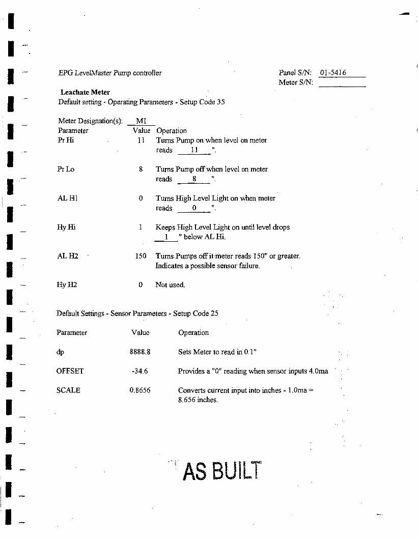
I I I I I I I I I I I I I I I I I I I
EPG LevelMaster Pump controller Panel SIN: 01-5416
Meter SIN:
Leachate Meter Default setting - Operating Parameters - Setup Code 3 5
Meter Designation(s):
Parameter Pr Hi
PrLo
ALHI
Hy Hi
ALH2
HyH2
Ml V aJue Operation
11 Tums Pump on when level on meter
reads 11 11
8 Tums Pump off when level on meter
reads 8 11
0 Tums High Level Light on when meter
reads O 11
I Keeps High Level Light on until level drops
1 " below AL Hi.
150 Tums Pumps off it meter reads 150" or greater.
Indicates a possible sensor failure.
0 Not used.
Default Settings - Sensor Parameters - Setup Code 25
Parameter
dp
OFFSET
SCALE
VaJue
8888.8
-34.6
0.8656
Operation
Sets Meter to read in 0. l 11
Provides a "0" reading when sensor inputs 4.0ma
Converts current input into inches - 1. Oma = 8.656 inches.
AS BUILT
--
I I -
I I I I I I I I I I-I I_ 1_
! I_-
1-II-
EPG Companies Inc.
CAUTION
EPG submersible level sensors are designed for rugged use. However, care should be taken to protect these devices from over pressure and sudden impact. When lowering the level sensor into a liquid, penetrate the su:rface slowly and only to the depth that the unit is designed for. Do not drop or wash with high pressure since this may damage the unit.
Bulletin 3360 © EPG Companies Inc. 2001
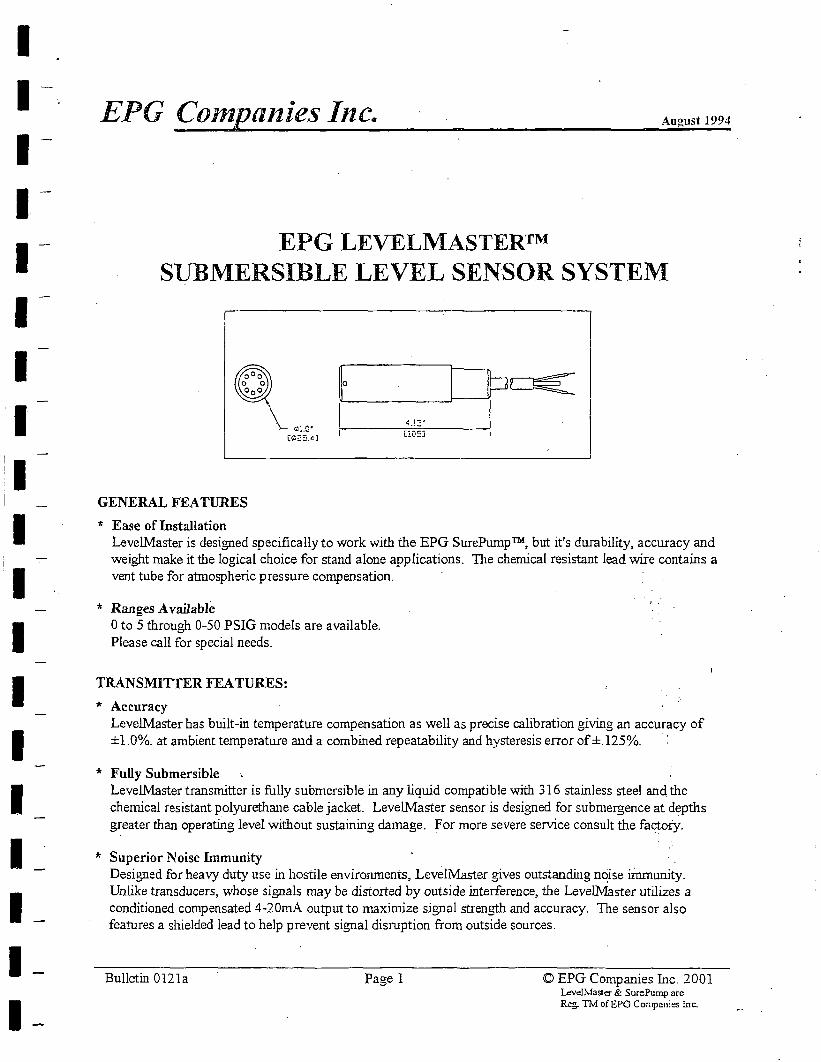
I I I I I I I I I I I I I I I I I I I
EPG Compa11ies Inc. August 1994
EPG LEVELMASTER™ SUBMERSIBLE LEVEL SENSOR SYSTEM
\_ 0,1,Q•
GENERAL FEATURES
* Ease of Installation LevelMaster is designed specifically to work with the EPG SurePump™, but it's durability, accuracy and weight make it the logical choice for stand alone applications. The chemical resistant lead wire contains a vent tube for atmospheric pressure compensation.
* Ranges Available 0 to 5 through 0-50 PSIG models are available. Please call for special needs.
TRANSMITTER FEATURES:
* Accuracy LevelMaster bas built-in temperature compensation as well as precise calibration giving an accuracy of ±1.0%. at ambient temperature and a combined repeatability and hysteresis error of ±.125%.
* Fully Submersible LevelMaster transmitter is fully submersible in any liquid compatible with 316 stainless steel and the chemical resistant polyurethane cable jacket. Leve!Master sensor is designed for submergence at depths greater than operating level without sustaining damage. For more severe service consult the factory.
* Superior Noise Immunity . Designed for heavy duty use in hostile environments, Leve!Master gives outstanding n~ise immunity. Unlike transducers, whose signals may be distorted by outside interference, the Levell\llaster utilizes a conditioned compensated 4-20mA output to maximize signal strength and accuracy. The sensor also features a shielded lead to help prevent signal disruption from outside sources.
Bulletin 0121a Pagel <O EPG Companies Inc. 2001 Leve]Master & SurePump are Reg. TM ofEPG Companies Inc.
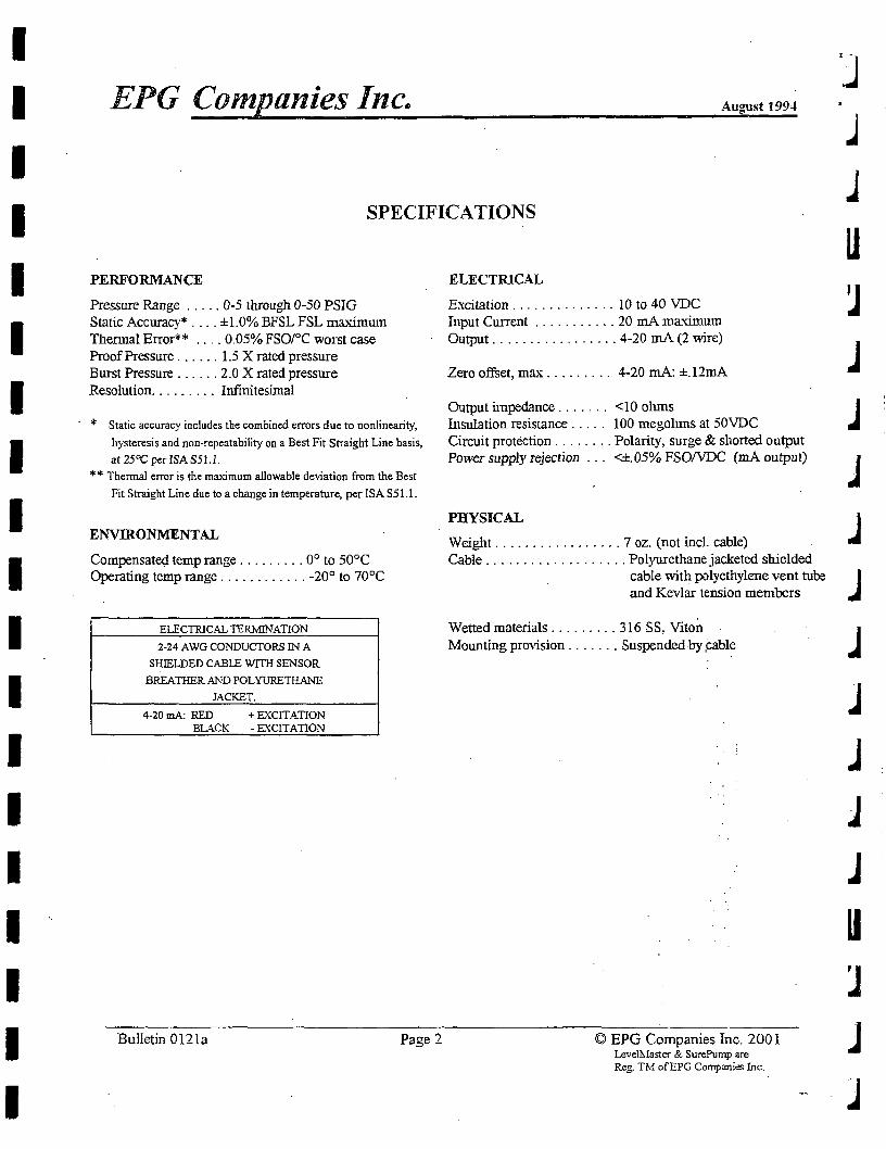
I I I I I I I I I I I I I I I I I I I
EPG Companies Inc~ August 199-1
SPECIFICATIONS
PERFORMANCE
Pressure Range ..... 0-5 through 0-50 PSIG Static Accuracy* .... ±1.0% BFSL FSL maximum Thermal Error** .... 0.05% FSO/°C worst case Proof Pressure ...... 1.5 X rated pressure Burst Pressure ...... 2.0 X rated pressure Resolution ......... Infinitesimal
* Static accuracy includes the combined errors due to nonlinearity,
hysteresis and non-repeatability on a Best Fit Straight Line basis,
at 25°C per ISA S51. l. ** Thermal error is the maximum allowable deviation from the Best
Fit Straight Line due to a change in temperature, per ISA S51.1.
ENVIRONMENTAL
Compensated temp range ......... 0° to 50°C Operating temp range ............ -20° to 70°C
ELECTRICAL TERMINATION
2-24 AWGCONDUCTORS IN A
SHIELDED CABLE WITH SENSOR
BREATHER AND POLYURETHANE
JACKET.
4-20mA: RED + EXCITATION BLACK - EXCITATION
Bulletin 0121a Page 2
ELECTRICAL
Excitation . . . . . . . . . . . . . . 10 to 40 VDC Input Current ........... 20 mA maximum Output ................. 4-20 mA (2 wire)
Zero offset, max . . . . . . . . . 4-20 mA: ±. l2rnA
Output impedance . . . . . . . <IO ohms Insulation resistance . . . . . 100 megoluns at 50VDC Circuit protection ........ Polarity, surge & shorted output Power supply rejection <±.05% FSO/VDC (mA output)
PHYSICAL
Weight ................. 7 oz. (not incl. cable) Cable ................... Polyurethane jacketed shielded
cable with polyethylene vent tube and Kevlar tension members
Wetted materials ......... 316 SS, Viton Mounting provision ....... Suspended by ,cable
© EPG Companies Inc. 2001 Level~faster & SurePump are Reg. TM ofEPG Companies Inc.
j
.J
u
J J J
j
J J j
J J u
J
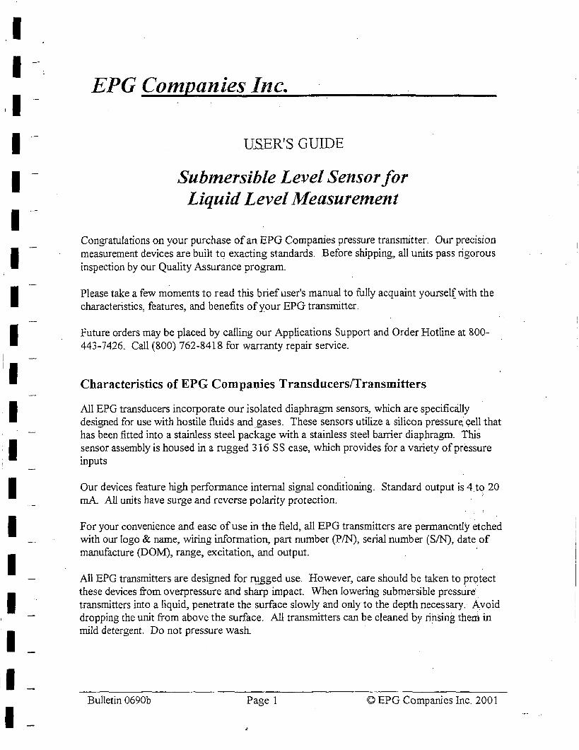
I I I I I I I I I
I I I I
I
EPG Companies Inc.
. USER'S GUIDE
Submersible Level Sensor for Liquid Level Measurement
Congratulations on your purchase of an EPG Companies pressure transmitter. Our precision measurement devices are built to exacting standards. Before shipping, all units pass rigorous inspection by our Quality Assurance program.
Please take a few moments to read this brief user's manual to fully acquaint yoursel( with the characteristics, features, and benefits of your EPG transmitter.
Future orders may be placed by calling our Applications Support and Order Hotline at 800-443-7426. Call (800) 762-8418 for warranty repair service.
Characteristics of EPG Companies Transducersffransmitters
All EPG transducers incorporate our isolated diaphragm sensors, which are specifically· designed for use with hostile fluids and _gases. These sensors utilize a silicon pressure. cell that has been fitted into a stainless steel package with a stainless steel banier diaphragm. This sensor assembly is housed in a rugged 316 SS case, which provides for a variety of pressure inputs
Our devices feature high performance internal signal conditioning. Standard output is 4.to 20 mA. All units have surge and reverse polarity protection.
For your convenience and ease of use in the field, all EPG transmitters are permanently etched with our logo & name, wiring information, part number (PIN), serial number (SIN), date of manufacture (DOM), range, excitation, and output.
All EPG transmitters are designed for ru._gged use. However, care should be taken to protect these devices from overpressure and sharp impact. When lowering submersible pressure· transmitters into a liquid, penetrate the surface slow!Y and only to the depth necessary. Avoid dropping the unit from above the surface. All transmitters can be cleaned by ri~sing them in mild detergent. Do not pressure wash.
Bulletin 0690b Page 1 © EPG Companies Inc. 2001
I I I I I I I I I I I I I I I I I I I
EPG Companies Inc.
Warranty
EPG Companies warrants its products against defects in material and workmanship for 12 months from date of shipment. Products not subjected to misuse will be repaired or replaced. THE FOREGOING IS IN LIEU OF ANY OTHER EXPRESSED OR IMJ>LIED . WARRANTIES. EPG Companies reserves the right to make changes to any product herein and assumes no liability arising out of the applications or use of any product or circuit described.
D0100-4 Vent Filter & Wate_r Vapor Trap
The DDI00-4 is a replaceable vent tube dehumidifier intended for use with our submersible pressure transmitters. This device is specifically designed to protect sensitive electronic components from mildew, corrosion, rust, and other forms of deterioration while at the same time preventing the formation of a liquid column.
Vent filters should be changed when they are 85% spent. Do not remove the old filter until a new one is available. The number one failure mode is moisture and corrosion damage due to lack of maintenance of the vent filter.
The DD 100-4 connects to the existing vent tube as it exits the cable at the junction box via a tube. The unbreakable acrylic drying tube is 4 inches in length and 3/4 inches in diameter. Inserted in each pull-off molded polypropylene drying tube end cap is a 20 micron · polypropylene filter.
The drying tube is filled with an indicating desiccant (drying agent). The maximum flow rate through the drying tube is 300 cubic centimeters per minute, more than sufficient to allow the transmitter to respond to barometric changes. As air passes through the drying tube, moisture is absorbed by the desiccant. The desiccant changes from blue to a rose red as its dryirig · . capacity becomes diminished.
The desiccant can be rejuvenated after normal use by spreading it in a layer one granule· deep and heating for one hour at 205°C (400°F). The heating temperature is very important for if it is lower than 205°C (400°F) the desiccant will not rejuvenate. Alternatively, if the desiccant is overheated, the crystal structure may be altered and render the desiccant permanently inactive. Alternatively, spare vent filters can be ordered by calling 800-443-7426. The DD 100~4 _vent filter and water vapor trap can be exposed to air, industrial gases, refrigerants, organic liquids, and solvents. It should not, however, be used when ammonia is present. · · ·
Bulletin 06906 Page2 © EPG Companies Inc. 2001
J j
j
u
J J J j
J J J
l J
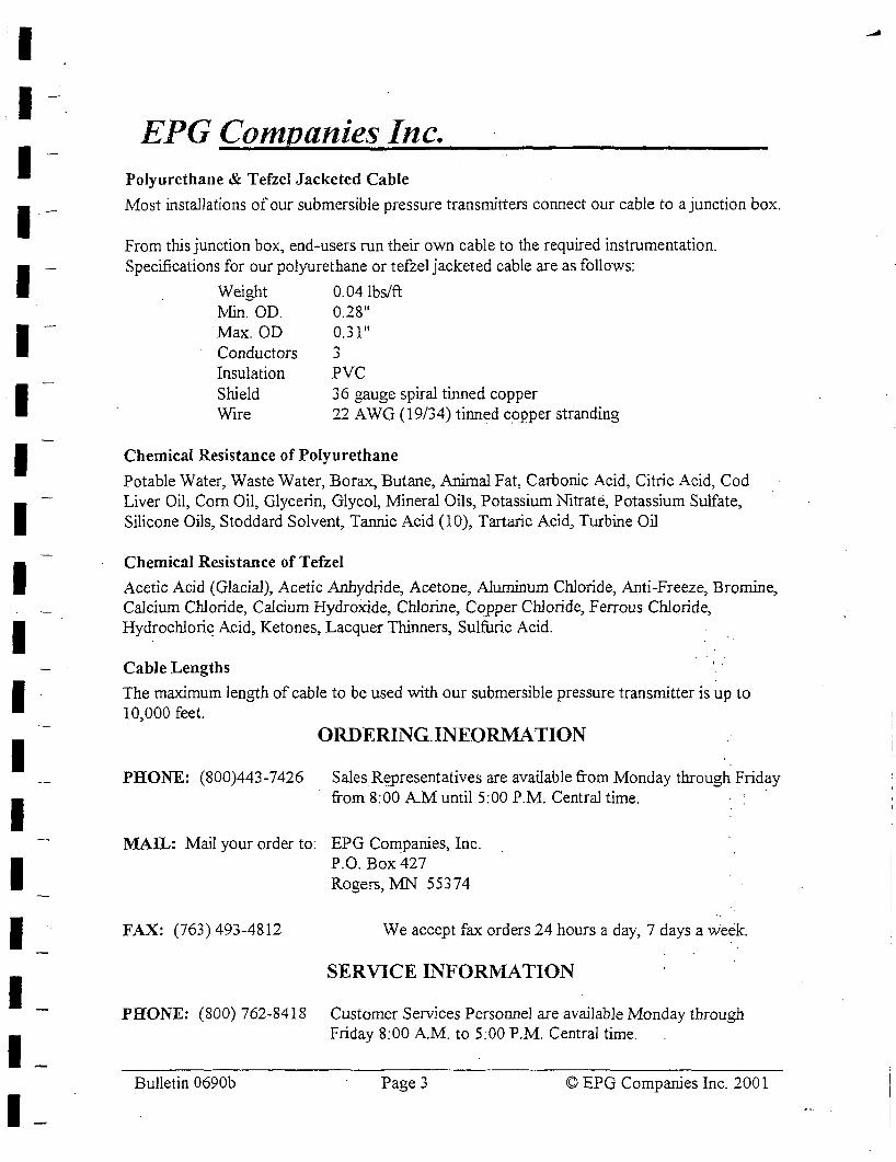
I I I I -
I I I I I I I I I I I I I I I -
EPG Companies Inc. Polyurethane & Tefzel Jacketed Cable
Most installations of our submersible pressure transmitters connect our cable to a junction box.
From this junction box, end-users run their own cable to the required instrumentation. Specifications for our polyurethane or tefzel jacketed cable are as follows:
Weight 0.04 lbs/ft l\tlin. OD. 0.28" Max. OD Conductors Insulation Shield
0.31" '"I .)
PVC 36 gauge spiral tinned copper
Wire 22 A WG ( 19/34) tinned cqpper stranding
Chemical Resistance of Polyurethane
Potable Water, Waste Water, Borax, Butane, Animal Fat, Carbonic Acid, Citric Acid, Cod Liver Oil, Corn Oil, Glycerin, Glycol, Mineral Oils, Potassium Nitrate, Potassium Sulfate, Silicone Oils, Stoddard Solvent, Tannie Acid (10), Tartaric Acid, Turbine Oil
Chemical Resistance of Tefzel
Acetic Acid (Glacial), Acetic Anhydride, Acetone, Aluminum Chloride, Anti-Freeze, Bromine, Calcium Chloride, Calcium Hydroxide, Chlorine, Copper Chloride, Ferrous Chloride, Hydrochlori~ Acid, Ketones, Lacquer Thinners, Sulfuric Acid.
Cable Lengths
The maximum length of cable to be used with our submersible pressure transmitter is up to 10,000 feet.
ORDERING.INEORMA TION
PHONE: (800)443-7426 Sales Re_presentatives are available from Monday through Friday from 8:00 A.M until 5:00 P.M. Central time.
MAIL: Mail your order to: EPG Companies, Inc.
FAX: (763) 493-4812
P.O. Box427 Rogers, iv1N 55374
We accept fax orders 24 hours a day, 7 days a week.
SERVICE INFORl\tlATION
PHONE: (800) 762-8418 Customer Services Personnel are available Monday through Friday 8:00 AM. to 5:00 P.M. Central time.
Bulletin 0690b Page 3 © EPG Companies Inc. 2001
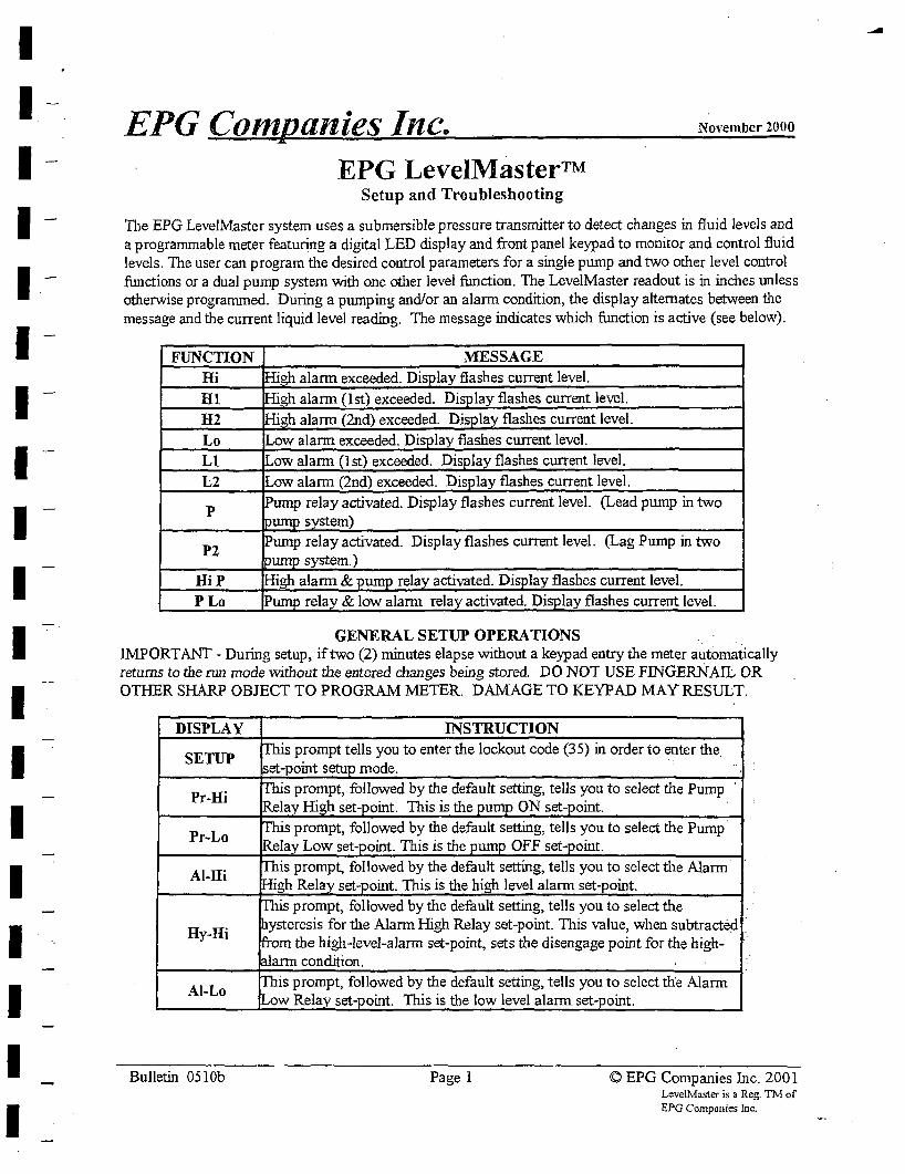
I I I I I I I I I I I I I I I I I I I
EPG Companies Inc. November 2000
EPG LeveIMaster™ Setup and Troubleshooting
The EPG LevelMaster system uses a submersible pressure transmitter to detect changes in fluid levels and a programmable meter featuring a digital LED display and front panel keypad to monitor and control fluid levels. The user can program the desired control parameters for a single pump and two other level control functions or a dual pump system with one other level function. The LeveIMaster readout is in inches unless otherwise programmed. During a pumping and/or an alarm condition, the display alternates between the message and the current liquid level reading. The message indicates which function is active (see below).
FUNCTION MESSAGE Hi High alarm exceeded. Display flashes current level.
Hl High alarm (1st) exceeded. DisPlay flashes current level.
H2 J-Iigh alarm (2nd) exceeded. Display flashes current level.
Lo Low alarm exceeded. DisPlay flashes current level.
Ll ILow alarm (1st) exceeded. DisPlay flashes current level.
L2 Low alarm (2nd) exceeded. Display flashes current level.
p Pump relay activated. Display flashes current level. (Lead pump in two oump system)
P2 !Pump relay activated. Display flashes current level. (Lag Pump in two pump system.)
HiP !High alarm & pump relay activated. DisPlay flashes current level.
PLo Purno relay & low alarm relay activated. DisPlay flashes current level.
GENERAL SETUP OPERATIONS IMPORTANT - During setup, if two (2) minutes elapse without a keypad entry the meter automatically returns to the run mode without the entered changes being stored. DO NOT USE FINGERNAIL OR OTHER SHARP OBJECT TO PROGRAM METER. DAMAGE TO KEYPAD MAY RESULT.
DISPLAY
SETUP
Pr-Hi
Al-Hi
Hy-Hi
Al-Lo
Bulletin 051 Ob
INSTRUCTION s you to enter the lockout code (35) in order to enter the ode. owed by the default setting, tells you to select the Pump oint. This is the oint.
, owed by the default setting, tells you to select the Pump· Low set- oint. This is the oint.
is prompt, followed by the default setting, tells you to select the Alarm ·gh Relay set- oint. This is the high level alarm set-point.
is prompt, followed by the default setting, tells you to select the ysteresis for the Alarm High Relay set-point. This value, when subtracted · om the high-level-alarm set-point, sets the disengage point for the high- · · la.rm condition.
is prompt, followed by the default setting, tells you to select th'e Alarm ow Relay set- oint. This is the low level alarm set- oint.
Page 1 © EPG Companies Inc. 2001 LeveHvfoster is a Reg. TM of EPG Companies Inc.
....
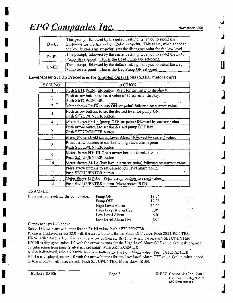
I I I I I I I I I I I I I I I I I I I
EPG Companies Inc. November 2000
prompt, followed by the default setting, tells you to select the Hy-Lo resis for the Alarm Low Relay set-point. This value, when added to
w-level-alarm set- oint, sets the disen oint for the low level.
Pr-Hl llowed by the current setting, tells you to select the Lead
oint. This is the Lead P oint.
Pr-H2 ollowed by the default setting, tells you to select the Lag oint. This is the La oint.
LevelMaster Set Up Procedures for Simplex Operations (SDHL meters only)
STEP NO. ACTION 1 [Push SETUP/ENTER button. Wait for the meter to display 0.
2 ~ush arrow buttons to set a value of 35 on meter display. [Push SETUP/ENTER.
3 !Meter shows Pr-Hi (pump ON set point) followed by current value.
4 Push arrow buttons to set the desired level for pump ON. Push SETUP/ENTER button.
5 Meter shows Pr-Lo (pump OFF set point) followed by current value.
6 Push arrow buttons to set the desired pump OFF level. Push SETUP/ENTER butt.on.
7 Meter shows Hi-Al (High Level Alarm) followed by current value.
8 Press arrow buttons to set desired high level alarm point. Push SETUP/ENTER button.
9 Meter shows HY-Hi. Press arrow buttons to select value. Push SETUP/ENTER button.
10 !Meter shows Al-Lo (low level alarm set point) followed by current value.
11 Press arrow buttons to set desired low level alarm point. Push SETUP/ENTER button. '.
12 Meter shows HY-Lo. Press arrow buttons to select value.
13 Push SETUP/ENTER button. Meter shows RUN.
EXAMPLE: If the desired levels for the pump were: Pump ON
Pump OFF 18.0" 12.0" 30.0"
Complete steps 1 - 3 above.
High Level Alarm High Level Alarm Hys. Low Level Aiarm Low Level Alarm Hys.
Select 18.0 with arrow buttons for the Pr-Hi value. Push SETUP/ENTER.
1.0" 6.0" 1.0"
Pr-Lo is displayed, select 12.0 ,vith the arrow buttons for the Pump OFF value. Push SETUP/ENTER.• Hi-AI is displayed, select 30.0 with the arrow buttons for the High Alarm value. Push SE1UP/ENTER; HY-Hi is displayed, select 1.0 with the arrow buttons for the High Level Alann OFF value (value determined by subtracting from high-level-alarm set-point). Push SETUP/ENTER. AI-Lo is displayed, select 6.0 with the arrow buttons for the Low Alarm value. Push SETUP/ENTER. HY-Lo is displayed, select I .0 with the arrow buttons for the Low Level Alarm OFF value (value, when added to Alarm point, will reset alarm). Push SETUP/ENTER. Meter shows RUN.
Bulletin 051 Ob Page 2 © EPG Companies Inc. 2001 LevelMaster is a Reg. TM of EPG Companies Inc.
j
j
J J J. j
]
J J J J u
·J J
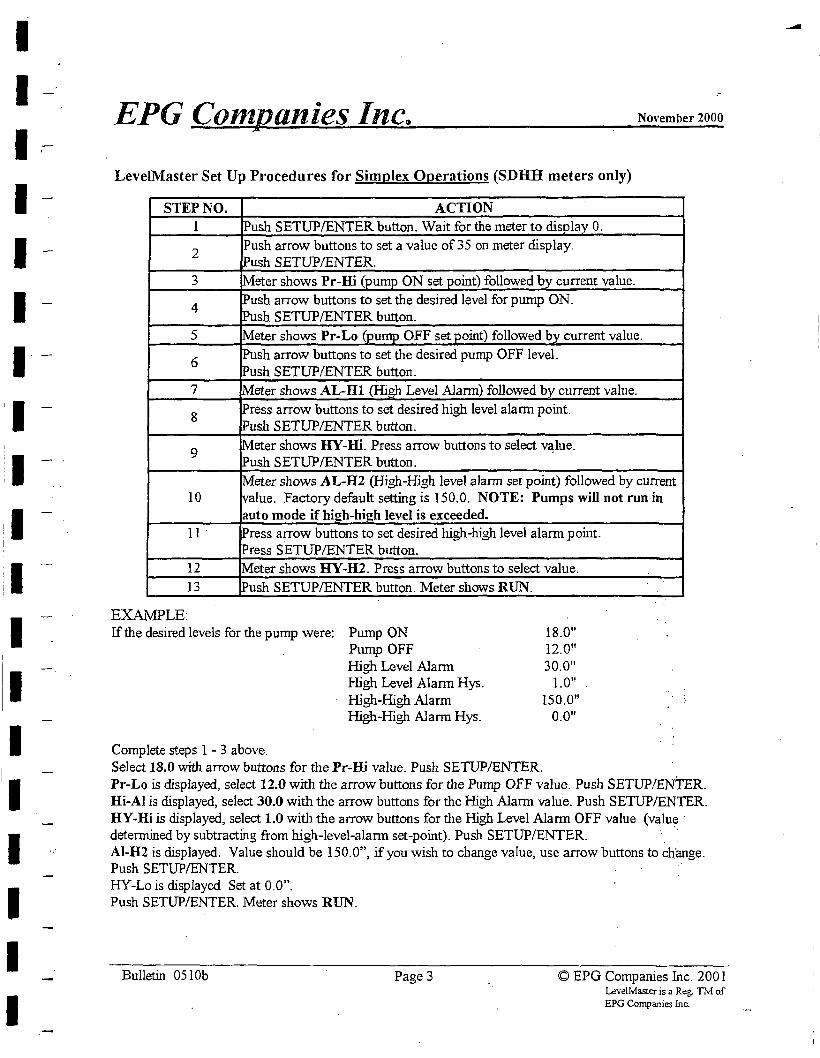
I I I -
I I I 1·
'I I I :1 I
:I I I
1• II
I I I I
EPG Conipanies Incqj November 2000
Level.Master Set Up Procedures for Simplex Operations (SDHH meters only)
STEP NO. ACTION 1 Push SETUP/ENTER button. Wait for the meter to display 0.
2 Push arrow buttons to set a value of 35 on meter display. Push SETUP/ENTER.
3 Meter shows Pr-Hi (pump ON set point) followed by current value.
4 !Push arrow buttons to set the desired level for pump ON. Push SETUP/ENTER button.
5 Meter shows Pr-Lo (pump OFF set point) followed by current value.
6 Push arrow buttons to set the desired pump OFF level. Push SETUP/ENTER button.
7 Meter shows AL-Hl (High Level Alarm) followed by current value.
8 Press arrow buttons to set desired high level alarm point. Push SETUP/ENTER button.
9 Meter shows HY-Hi. Press arrow buttons to select v~lue. Push SETUP/ENTER button.
Meter shows AL-H2 (High-High level alarm set point) followed by current 10 value. Factory default setting is 150.0. NOTE: Pumps will not run in
auto mode if high-hieh level is exceeded. 11. Press arrow buttons to set desired high-high level alarm point.
!Press SETUP/ENTER button. 12 Meter shows HY-ID. Press arrow buttons to select value.
13 !Push SETUP/ENTER button. Meter shows RUN.
EXAMPLE: If the desired levels for the pump were: Pump ON
Pump OFF 18.0" 12.0" 30.0"
Complete steps 1 - 3 above.
High Level Alarm High Level Alarm Hys. High-High Alarm High-High Alarm Hys.
1.0" 150.0"
0.0"
Select 18.0 with arrow buttons for the Pr-Hi value. Push SETUP/ENTER. Pr-Lo is displayed, select 12.0 with the arrow buttons for the Pump OFF value. Push SETUP/ENTER. Hi-Al is displayed, select 30.0 with the arrow buttons for the High Alarm value. Push SETUP/ENTER. HY-Hi is displayed, select 1.0 with the arrow buttons for the High Level Alarm OFF value (value · detennined by subtracting from high-level-alarm set-point). Push SETUP/ENTER. Al-ID is displayed. Value should be 150.0", if you wish to change value, use arrow buttons to change. Push SETUP/ENTER. HY-Lo is displayed Set at 0.0". Push SETUP/ENTER. Meter shows RUN.
Bulletin 051 Ob Page 3 © EPG Companies Inc. 200 I Leve!Master is a Reg. Th[ of EPG Companies Inc.
-
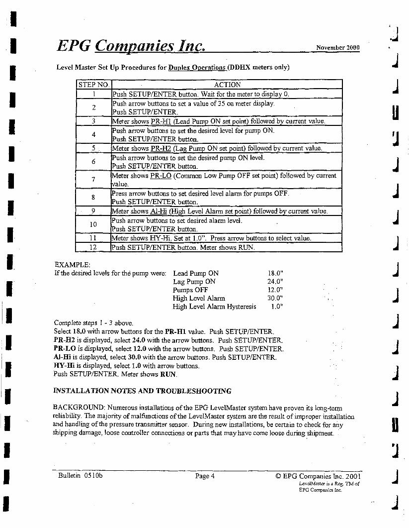
I I I I :I I II.
I I I I I I I I I
EPG Companies Inc. November 2000
Level Master Set Up Procedures for Duplex Operations (DDHX meters only)
STEP NO. ACTION 1 Push SETUP/ENTER button. Wait for the meter to display 0.
2 Push arrow buttons to set a value of 35 on meter display. IPusb SETUP/ENTER.
3 !Meter shows PR-HI (Lead Pump ON set point) followed by current value.
4 !Push arrow buttons to set the desired level for pump ON. IPush SETUP/ENTER button.
5. !Meter shows PR-H2 (Lag Pump ON set point) followed by current value.
6 Push arrow buttons to set the desired pump ON level. !Push SETUP/ENTER button.
7 Meter shows PR-LO (Common Low Pump OFF set point) followed by current tvalue.
8 IPress arrow buttons to set desired level alarm for pumps OFF. !Push SETUP/ENTER button.
9 Meter shows Al-Hi (High Level Alarm set point) followed by current value.
10 IPush arrow buttons to set desired alarm level. Push SETUP/ENTER button.
11 Meter shows HY-Hi. Set at 1.0". Press arrow buttons to select value. 12 IPush SETUP/ENTER button. Meter shows RUN.
EXAMPLE: If the desired levels for the pump were: Lead Pump ON 18.0"
Lag Pump ON 24.0" Pumps OFF 12.0" High Level Alarm 30.0'' High Level Alarm Hysteresis 1.0"
Complete steps 1 - 3 above. Select 18.0 with arrow buttons for the PR-Bl value. Push SETUP/ENTER. PR-H2 is displayed, select 24.0 with the arrow buttons. Push SETUP/ENTER. PR-LO is displayed, select 12.0 with the arrow buttons. Push SETUP/ENTER. Al-Hi is displayed, select 30.0 with the arrow buttons. Push SETUP/ENTER. HY-Hi is displayed, select 1.0 with arrow buttons. Push SETUP/ENTER. Meter shows RUN.
INSTALLATION NOTES AND TROUBLESHOOTING
BACKGROUND: Numerous installations of the EPG LevelMaster system have proven its long-te~ reliability. The majority of malfunctions of the LevelMaster system are the result of improper installation and handling of the pressure transmitter sensor. During new installations, be certain to check for any shipping damage, loose controller connections or parts that may have come loose during shipment. .
Bulletin 051 Ob Page4 © EPG Companies Inc. 2001 Lev<!!Master is a Reg. TM of EPG Companies Inc.
J j
.J
u
j
j
j
.J
j
j
j
J u
j
j
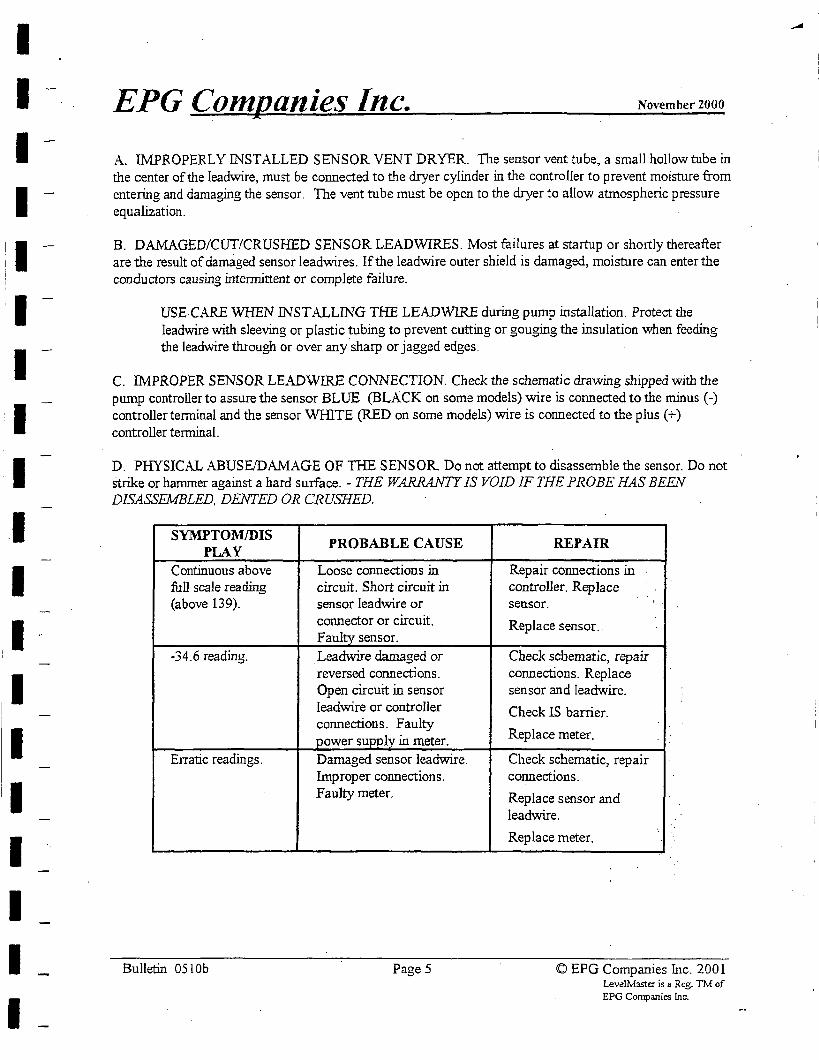
I I I I
!1 I
i
I I I I I I I I
I I
EPG Companies Inc. November 2000
A. IMPROPERLY INSTALLED SENSOR VENT DRYER. The sensor vent tube, a small hollow tube in the center of the Ieadwire, must be connected to the dryer cylinder in the controller to prevent moisture from entering and damaging the sensor. The vent tube must be open to the dryer to allow atmospheric pressure equalization.
B. DAMAGED/CUT/CRUSHED SENSOR LEADWIRES. Most failures at startup or shortly thereafter are the result of damaged sensor leadwires. If the leadwire outer shield is damaged, moisture can enter the conductors causing intermittent or complete failure.
USE CARE WHEN INST ALLING THE LEADWIRE during pwnp instalJation. Protect the Jeadwire with sleeving or plastic ~bing to prevent cutting or gouging the insulation when feeding the leadwire through or over any sharp or jagged edges.
C. IMPROPER SENSOR LEADWIRE CONNECTION. Check the schematic drawing shipped with the pump controller to assure the sensor BLUE (BLACK on some models) wire is connected to the minus(-) controller terminal and the sensor WHITE (RED on some models) wire is connected to the plus(+) controller terminal.
D. PHYSICAL ABUSE/DAMAGE OF THE SENSOR. Do not attempt to disassemble the sensor. Do not strike or hammer against a hard surface. - THE WARRANTY JS VOID IF THE PROBE HAS BEEN DISASSEMBLED, DENTED OR CRUSHED.
SYMPTOM/DIS PROBABLE CAUSE PLAY
Continuous above Loose connections in full scale reading circuit. Short circuit in (above 139). sensor leadwire or
connector or circuit. Faulty sensor.
-34.6 reading. Leadwire damaged or reversed connections. Open circuit in sensor leadwire or controller connections. Faulty power supply in meter.
Erratic readings. Damaged sensor leadwire. Improper connections. Faulty meter.
Bulletin 051 Ob Page 5
REPAIR
Repair connections in controller. Replace sensor.
Replace sensor..
Check schematic, repair connections. Replace sensor and leadwire.
Check IS barrier.
Replace meter.
Check schematic, repair connections.
Replace sensor and leadwire.
Replace meter. ·•
~
<D EPG Companies Inc. 2001 l.eve!Master is a Reg. TM of EPG Companies Inc:.
-
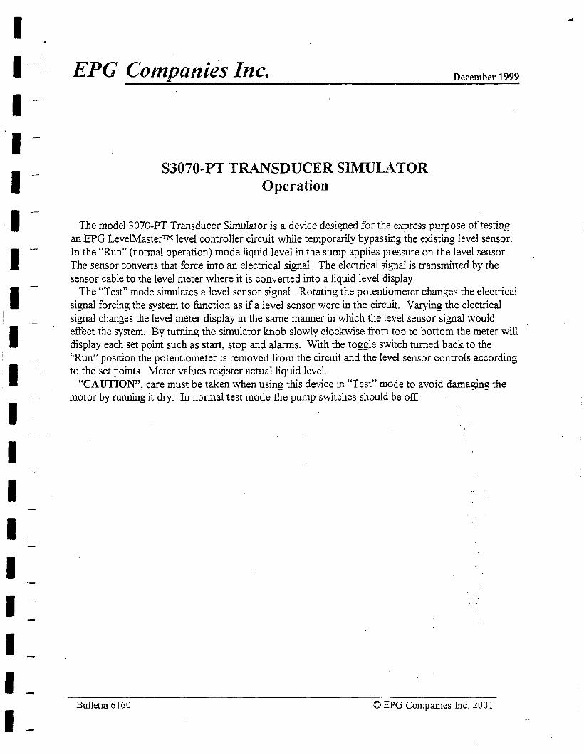
I I I I I I I I I-I I I I I I I I I I
EPG Companies Inc.
S3070-PT TRANSDUCER SIMULATOR Operation
December 1999
The model 3070-PT Transducer Simulator is a device designed for the express purpose of testing an EPG LevelMaster™ level controller circuit while temporarily bypassing the existing level sensor. In the ''Run" (nomial operation) mode liquid level in the sump applies pressure on the level sensor. The sensor converts that force into an electrical signal. The electrical signal jg transmitted by the sensor cable to the level meter where it is converted into a liquid level display.
The "Test" mode simulates a level sensor signal. Rotating the potentiometer changes the electrical signal forcing the system to function as if a level sensor were in the circuit. Varying the electrical signal changes the level meter display in the same manner in which the level sensor signal would effect the system. By turning the simulator knob slowly clockwise from top to bottom the meter will display each set point such as start, stop and alarms. With the toggle switch turned back to the ''Run" position the potentiometer is removed from the circuit and the level sensor controls according to the set points. Meter values register actual liquid level.
"CAUTION", care must be taken when using this device in "Test" mode to avoid damaging the motor by running it dry. In normal test mode the pump switches should be off
Bulletin 6160 © EPG Companies Inc. 200 I
I I I I I I I I I I I I I I I I I I I
EPG Companies IncQ
S3070-PT TRANSDUCER SIMULATOR TEST PROCEDURE
December 1999
1. When the toggle switch is in the "Run" position the controls should function normally. 2. When the toggle switch is in the "Tesf'_position (pressure transducer temporarily removed from
he control circuit) the level meter should display the liquid level. By turning the simulator knob slowly clockwise from top to bottom the meter will display each set point such as start, stop, and alarms. Care must be taken when using this device in the "Test" mode to avoid damaging the motor by running it dry. In normal test mode the _purp.p switches should be off
3 .. Make sure that the potentiometer has full travel (270 degrees maximum) in both clockwise and counter-clockwise directions.
4. Make sure that all of the wires on the rear ofthe simulator (wires 200,201,202,203) are connected in the proper position.
5. Replace the transducer simulator if it does not function as described above.
Bulletin 6165 © EPG Companies Inc. 2001
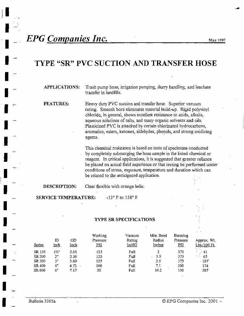
I I I I I I I I I I I I I I I I I I I
EPG Companies Inc. May 1997
TYPE "SR" PVC SUCTION AND TRANSFER HOSE
APPLICATIONS: Trash pump hose, irrigation pumping, slurry handling, and leachate transfer in landfills.
FEATURES: Heavy duty PVC suction and transfer hose. Superior vacuum rating. Smooth bore eliminates material build-up. Rigid polyvinyl chloride, in general, shows excellent resistance to acids, alkalis, aqueous solutions of salts, and many organic solvents and oils. Plasticized PVC is attacked by certain chlorinated hydrocarbons, aromatics, esters, ketones, aldehydes, phe1!ols, and strong oxidizing agents.
This chemical resistance is based on tests of specimens conducted by completely submerging the hose sample in the listed chemical or reagent. In critical applications, it is suggested that greater reliance be placed on actual field experience or that testing be performed under conditions of stress, exposure, temperature and duration which can be related to the anticipated application. ·
DESCRIPTION: Clear flexible with orange helix.
SERVICE TEMPERATURE: -13° F to 158° F
TYPE SR SPECIFICATIONS
Working Vacuum Min.Bend Bursting ID OD Pressure Rating Radius Pressure Approx. Wt.
Series Inch Inch PSI In/HG Inches PSI Lbs./100 Ft.
SR 150 l½" 2.01 125 Full 2 375 ·. 41
SR200 2" 2.56 125 Full 3.5 375 65 SR300 ~ .. 3.60 125 Full 3.5 315 · 107 .)
SR400 4" 4.72 100 Full 7.1 300 174 SR600 6" 7.17 50 Full 10.2 150 387
Bulletin 3305a © EPG Companies Inc. 2001 -,.
- i
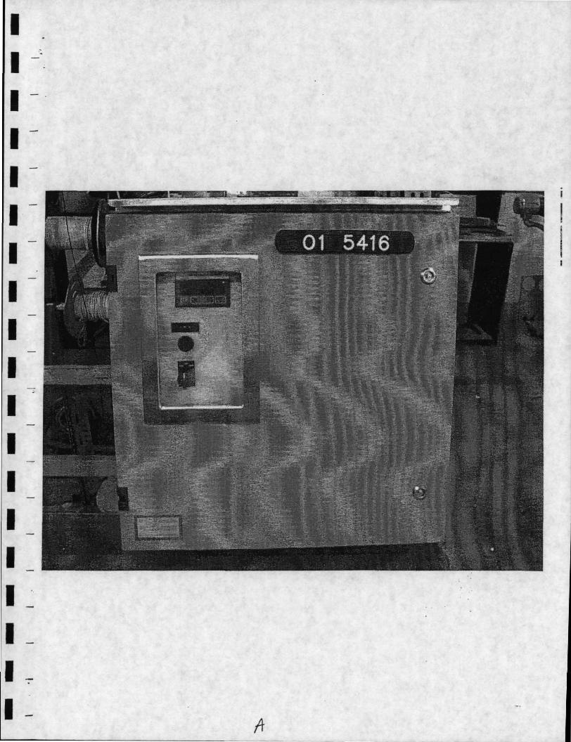
I -I -~:
I - -I -I -
I
I I
I I I
-
I I I I I I I I I ~ I -I 7
I -
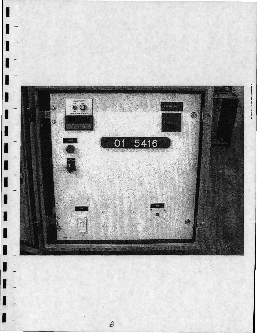
I I I I I I I I I I I I I I I I I I I
8
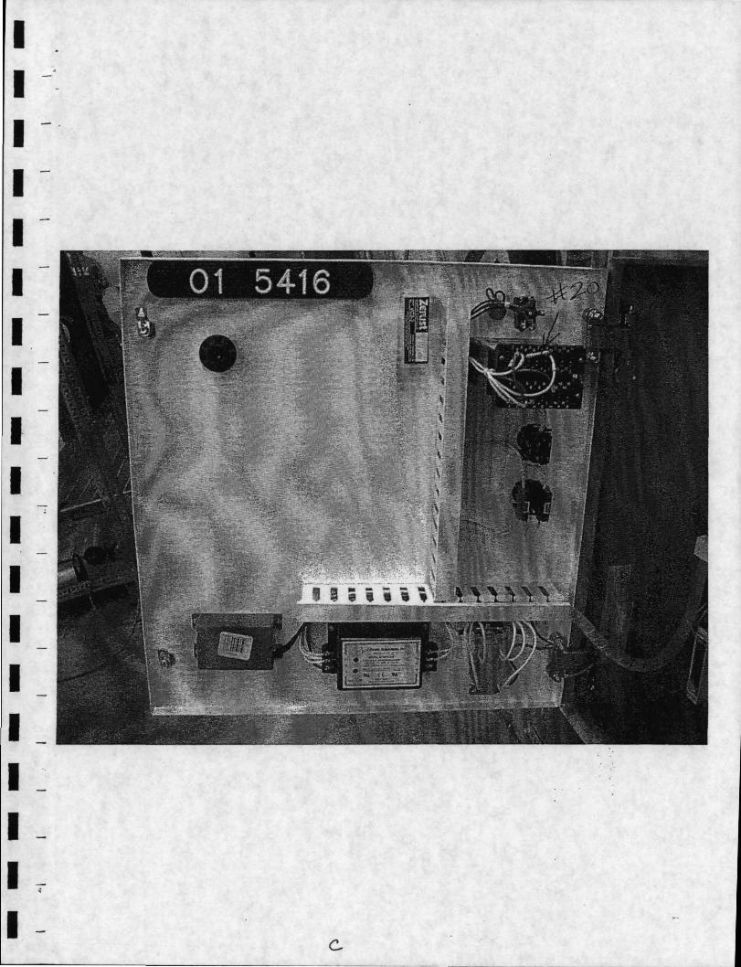
I I I I I I I I I· I I I I I I I I I -;;
I c..
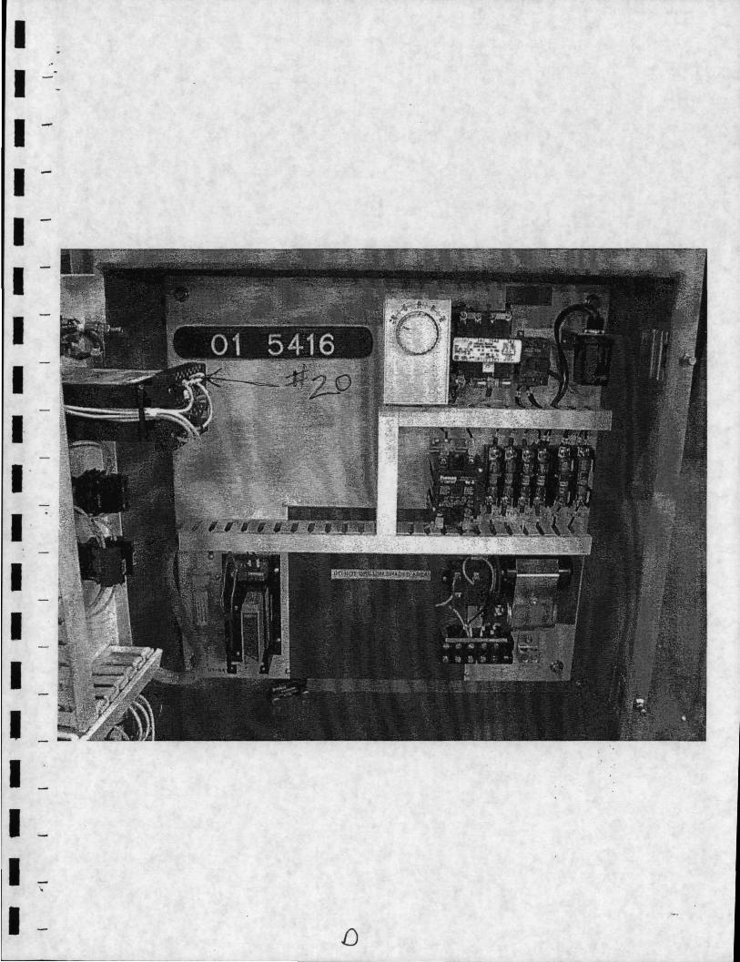
I I I -I I I I I I· 1-I I I I I I I I ·,
I [)
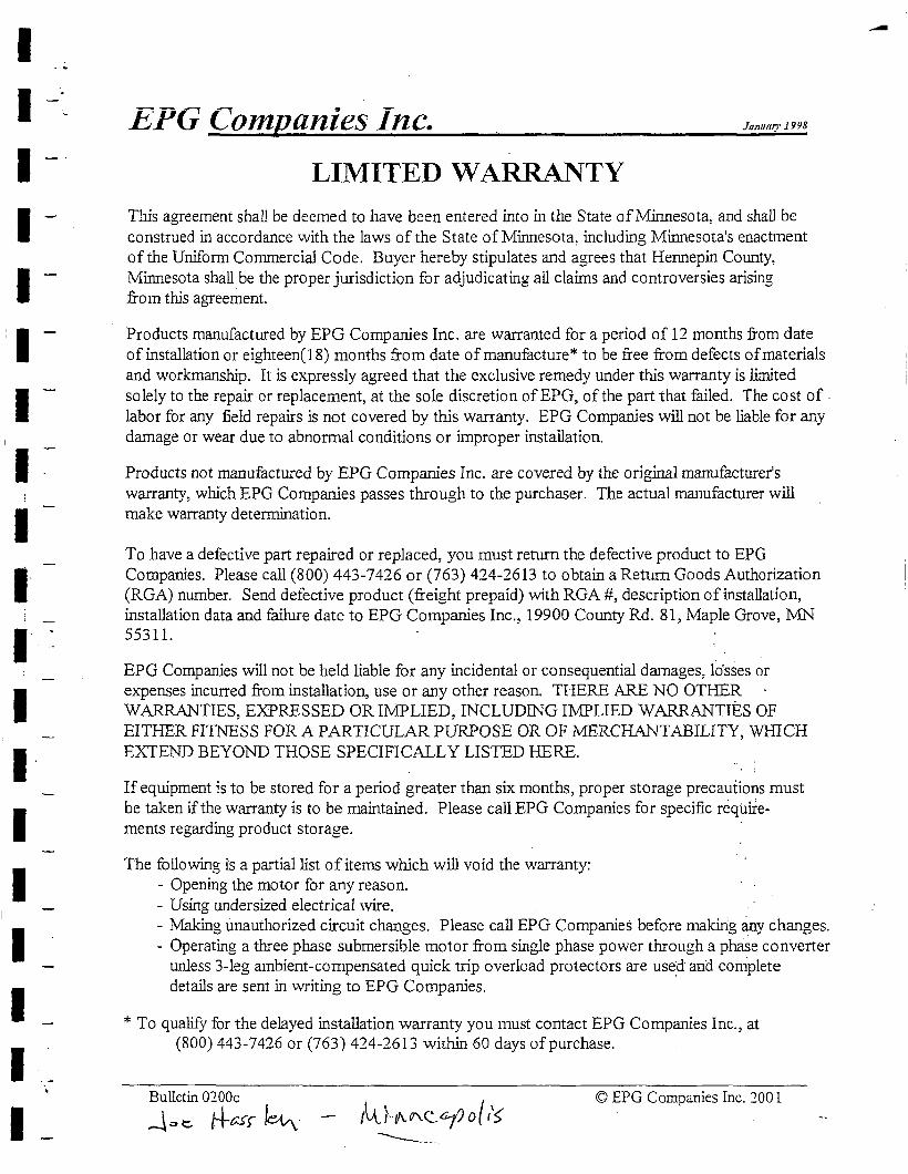
I I I I I I I I I 1·
;
I I I· I I I I I I
h'.PG Companies Inc. January 1998
LIMITED WARRANTY This agreement shall be deemed to have been entered into in the State of Minnesota, and shall be construed in accordance with the laws of the State of Minnesota, including Minnesota's enactment of the Uniform Commercial Code. Buyer hereby stipulates and agrees that Hennepin County, Minnesota shall be the proper jurisdiction for adjudicating all claims and controversies arising from this agreement.
Products manufactured by EPG Companies Inc. are warranted for a period of 12 months from date of installation or eighteen( 18) months from date of manufacture* to be free from defects of materials and workmanship. It is expressly agreed that the exclusive remedy under this warranty is limited solely to the repair or replacement, at the sole discretion of EPG, of the part that failed. The cost of. labor for any field repairs is not covered by this warranty. EPG Companies will not be liable for any damage or wear due to abnormal conditions or improper installation.
Products not manufactured by EPG Companies Inc. are covered by the original manufacturer's warranty, which EPG Companies passes through to the purchaser. The actual manufacturer will make warranty determination.
To have a defective part repaired or replaced, you must return the defective product to EPG Companies. Please call (800) 443-7426 or (763) 424-2613 to obtain a Return Goods Authorization (RGA) number. Send defective product (freight prepaid) with RGA #, description of installation, installation data and failure date to EPG Companies Inc., 19900 County Rd. 81, Maple Grove, :MN 55311.
EPG Companies will not be held liable for any incidental or consequential damages, lo'sses or expenses incurred from installation, use or any other reason. THERE ARE NO OTHER WARRANTIES, EXPRESSED OR IMPLIED, INCLUDING I:M:PLIED WARRANTIES OF EITHER FITNESS FOR A PARTICULAR PURPOSE OR OF MERCHANTABILITY, WHICH EXTEND BEYOND THOSE SPECIFICALLY LISTED HERE.
If equipment is to be stored for a period greater than six months, proper storage precautions must be taken if the warranty is to be maintained. Please call EPG Companies for specific require-ments regarding product storage. ·
The following is a partial list of items which will void the warranty: - Opening the motor for any reason. - Using undersized electrical wire. - Making unauthorized circuit changes. Please call EPG Companies before makirig any changes. - Operating a three phase submersible motor from single phase power through a phase converter
unless 3-leg ambient-compensated quick trip overload protectors are used and complete details are sent in writing to EPG Companies.
* To qualify for the delayed installation warranty you must contact EPG Companies Inc., at (800) 443-7426 or (763) 424-2613 within 60 days of purchase.
Bulletin 0200c
..j., t=- f+ur I~- ,l..t } .. "'- {T\_ c__ cf o { /s © EPG Companies Inc. 2001
----- .
--
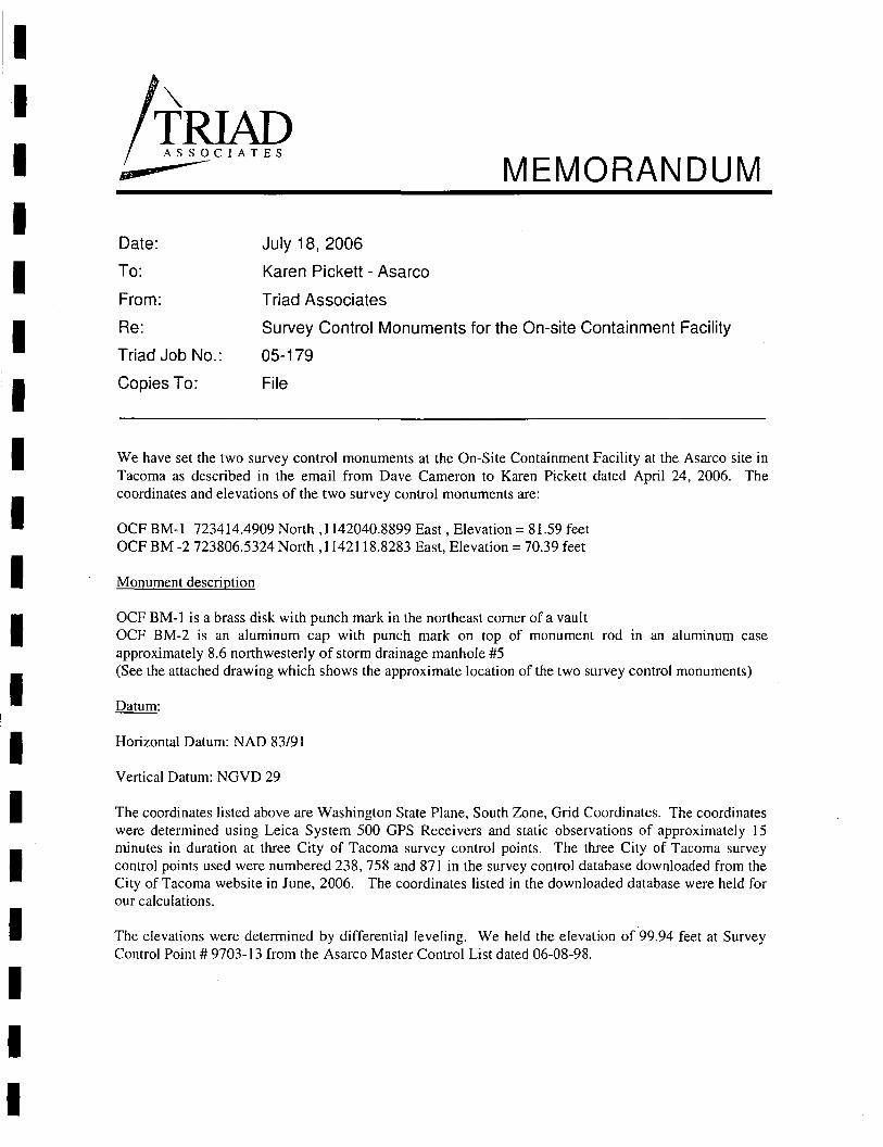
I I I I I I I I I I I I I I I I I I I
Date:
To:
From:
Re:
Triad Job No.:
Copies To:
July 18, 2006
Karen Pickett - Asarco
Triad Associates
MEMORANDUM
Survey Control Monuments for the On-site Containment Facility
05-179
File
We have set the two survey control monuments at the On-Site Containment Facility at the Asarco site in Tacoma as described in the email from Dave Cameron to Karen Pickett dated April 24, 2006. The coordinates and elevations of the two survey control monuments are:
OCF BM-I 723414.4909 North ,1142040.8899 East, Elevation= 81.59 feet OCF BM -2 723806.5324 North ,1142118.8283 East, Elevation= 70.39 feet
Monument description
OCF BM-I is a brass disk with punch mark in the northeast corner of a vault OCF BM-2 is an aluminum cap with punch mark on top of monument rod in an aluminum case approximately 8.6 northwesterly of storm drainage manhole #5 (See the attached drawing which shows the approximate location of the two survey control monuments)
Datum:
Horizontal Datum: NAD 83/91
Vertical Datum: NGVD 29
The coordinates listed above are Washington State Plane, South Zone, Grid Coordinates. The coordinates were determined using Leica System 500 GPS Receivers and static observations of approximately 15 minutes in duration at three City of Tacoma survey control points. The three City of Tacoma survey control points used were numbered 238, 758 and 871 in the survey control database downloaded from the City of Tacoma website in June, 2006. The coordinates listed in the downloaded database were held for our calculations.
The elevations were detennined by differential leveling. We held the elevation of 99.94 feet at Survey Control Point# 9703-13 from the Asarco Master Control List dated 06-08-98.
I I I I I I I I I I I I I I I I I I I OCF-OMMP-January 2007.doc
APPENDIXC
Contact Information
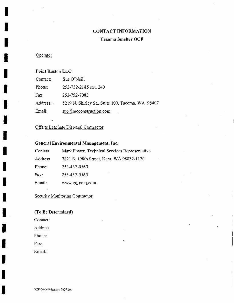
I I I I I I I I I I I I I I I I I I I
Operator
Point Ruston LLC
Contact: Sue O'Neill
CONT ACT INFORMATION
Tacoma Smelter OCF
Phone: 253-752-2185 ext. 240
Fax: 253-752-7083
Address: • 52 l 9 N. Shirley St., Suite l 00, Tacoma, WA 98407
Email: [email protected]
Offsite Leachate Disposal Contractor
General Environmental Management, Inc.
Contact: Mark Foster, Technical Services Representative
Address 7821 S. 198th Street, Kent, WA 98032-1120
Phone: 253-437-0560
Fax: 253-437-0565
Email: www.go-gem.com
Security Monitoring Contractor
(To Be Determined)
Contact:
Address
Phone:
Fax:
Email:
OCF-OMMP-January 2007.doc
I I I I I I I I I I I I I I I I I I I I OCF-OMMP-January 2007.doc
APPENDIXD
OCF Irrigation System Design
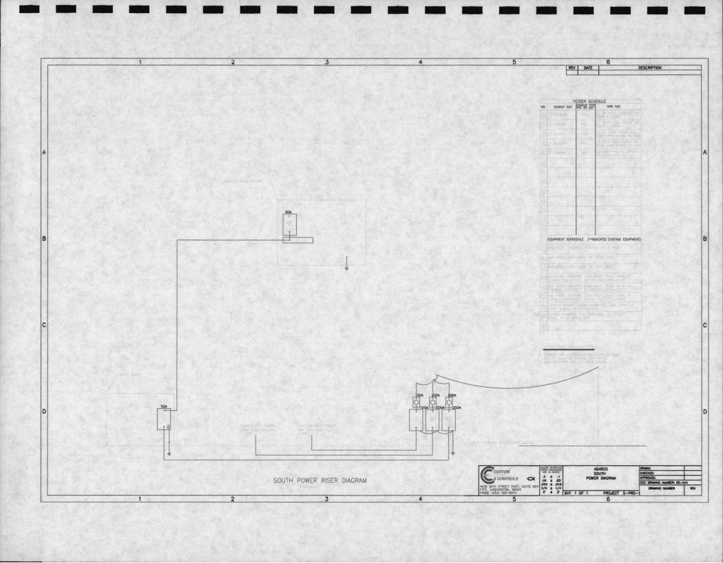
- - - - - - - - - - - - - - - - - - -2 3 4 5 6
MV D<T[
A A
B tOUN[WT SOCl(IU.[ (--..::Alt$ txaTIG ti:PWNT) B
l
C C
D D
·-------------------------------
SOUTH POWER RISER DIAGRAM
2 3 4 5 6
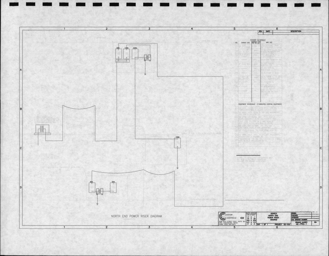
- - - - - - - - - - - - -2
A
B
C
D
NORTH END POWER RISER DIAGRAM
2 3 4
- - - -5 6
REV 1M1t
r~ll!_'!. SCHEOW: Ill. CIIICUtllll~ ...
5
-N0IITH [II) ---6
- -
A
B
C
D
-- ..
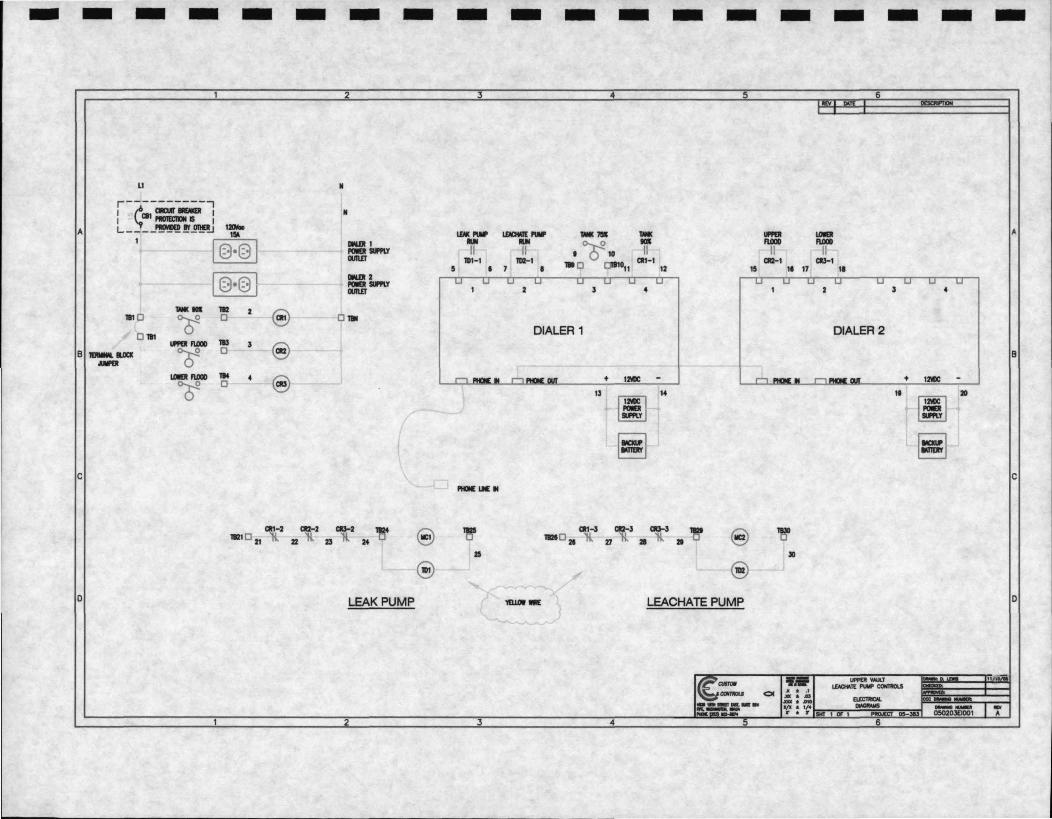
- - - - - - - - -2 3
LI • r--- -------7 I ~ml :,..-:a I • I ,_. 11 onol 1Dllc A L----- ----- '!..I 15'. I.EIII{ 1'111'
1§·§1 11111111 ... POEI UPIY 11 CIUIID
1§·§1 1111111 2 POEIUPIY OUIID -- 112 2 e 111 0 (; □ □ -
□ 111 IMl fUJOD 1IS .,
@) B 1EMlllll.llCIC (; □ MIPIII
I.Olllt fUJ0D 1M 4 E) (; □
C MIN[ LIE ti
atl-2 CIIZ-2 CIJ-2 ~ e ~ 1121 □ 21 ll 22 ll 23 ll 24
15
e 0 LEAK PUMP
2 3
- -4
I.EllClllll[l'III' ... II
2 .,
DIALER 1
♦
13
atl-3 1121□ 21 ll 27
'IIUOI-
4
- - -5
-.. II
15
4
IMC
151 14
~
l cm-3 aw E) • ll
@
LEACHATE PUMP
-c:am,ou
-
..... fUl0D
II c:112-1
1t 17
311
.,.
- - -6
I.Olllt fUl0D
II CIJ-1
II
s
DIALER 2
1t
._ ..... , 1£'1CHO
I !, I
I I I I I I I
APPENDIXE
I Report Forms
I I I I I I I I I OCF-OMMP-January 2007.doc
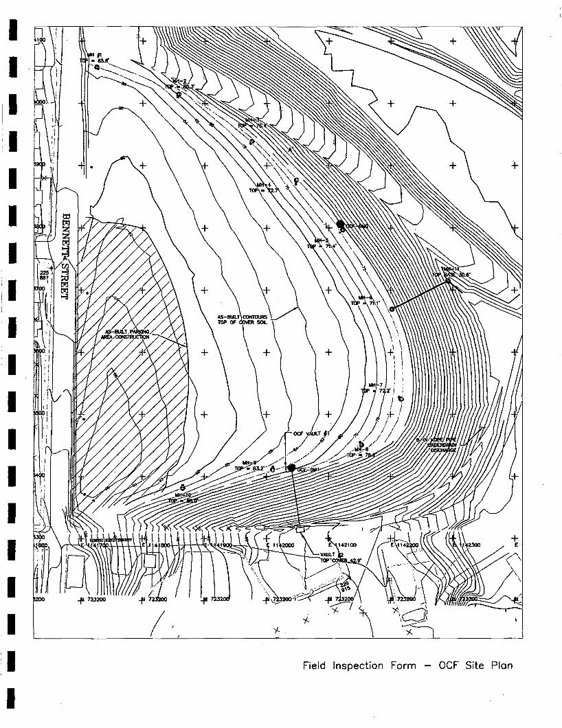
I I
11 I I I I ; I I I I I I I I I I I I
\ \
T,
./ ,y;•'t\l ' ;;,-
, ... ' l _.t,j 7 200'1~--' ,.. ~ \ ' )(:I
' -~- -f- ' --/ . _,-.1 ~
; , , .
+ E
:,,,,-'\ \
\
- OCF Site Plan r Form Field lnspec ion
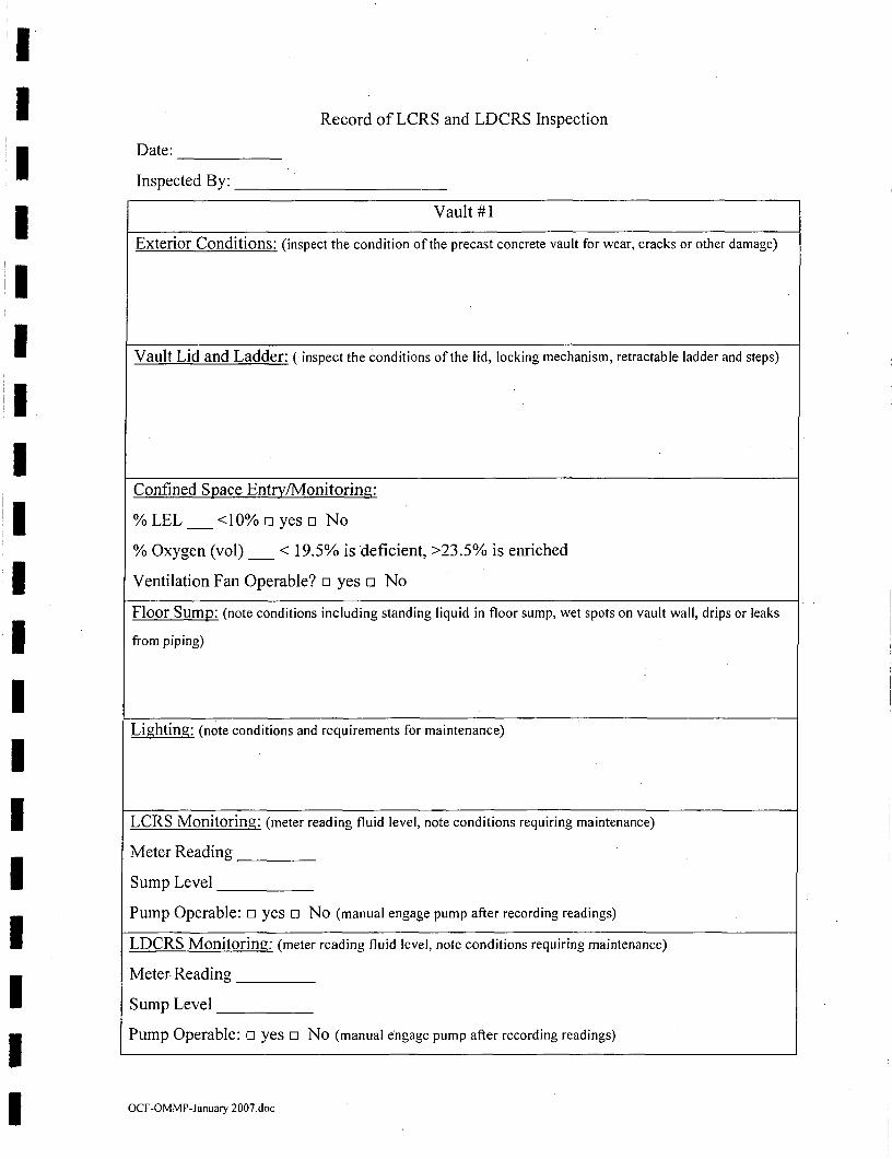
I I I I I I I I I I I I I I I I I I I
Record of LCRS and LDCRS Inspection
Date: ------Inspected By: ------------
Vault #1
Exterior Conditions: (inspect the condition of the precast concrete vault for wear, cracks or other damage)
Vault Lid and Ladder: ( inspect the conditions of the lid, locking mechanism, retractable ladder and steps)
Confined Space Entry/Monitoring:
% LEL_<l0% o yes o No
% Oxygen (vol)_< 19.5% is deficient, >23.5% is enriched
Ventilation Fan Operable? □ yes □ No
Floor Sump: (note conditions including standing liquid in floor sump, wet spots on vault wall, drips or leaks
from piping)
Lighting: (note conditions and requirements for maintenance)
LCRS Monitoring: (meter reading fluid level, note conditions requiring maintenance)
Meter Reading
Sump Level
Pump Operable: □ yes □ No (manual engage pump after recording readings)
LDCRS Monitoring: (meter reading fluid level, note conditions requiring maintenance)
Meter Reading
Sump Level
Pump Operable: □ yes □ No (manual engage pump after recording readings)
OCF-OMMP-January 2007.doc
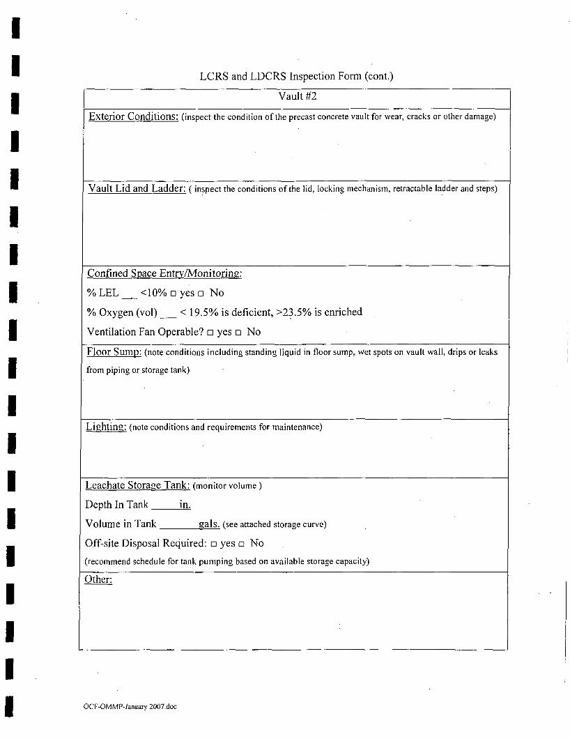
I I I I I I I I I I I I I I I I I I I
LCRS and LDCRS Inspection Fonn (cont.)
Vault #2
Exterior Conditions: (inspect the condition of the precast concrete vault for wear, cracks or other damage)
Vault Lid and Ladder: ( inspect the conditions of the lid, locking mechanism, retractable ladder and steps)
Confined Space Entry/Monitoring:
%LEL _<10% □ yes □ No
% Oxygen (vol) _ < 19.5% is deficient, >2~.5% is enriched
Ventilation Fan Operable? □ yes □ No
Floor Sump: (note conditions including standing liquid in floor sump, wet spots on vault wall, drips or leaks
from piping or storage tank)
Lighting: (note conditions and requirements for maintenance)
Leachate Storage Tanlc (monitor volume)
Depth In Tank m.
Volume in Tank gals. (see attached storage curve)
Off-site Disposal Required: □ yes □ No
(recommend schedule for tank pumping based on available storage capacity)
Other:
OCF-OMMP-January 2007.doc
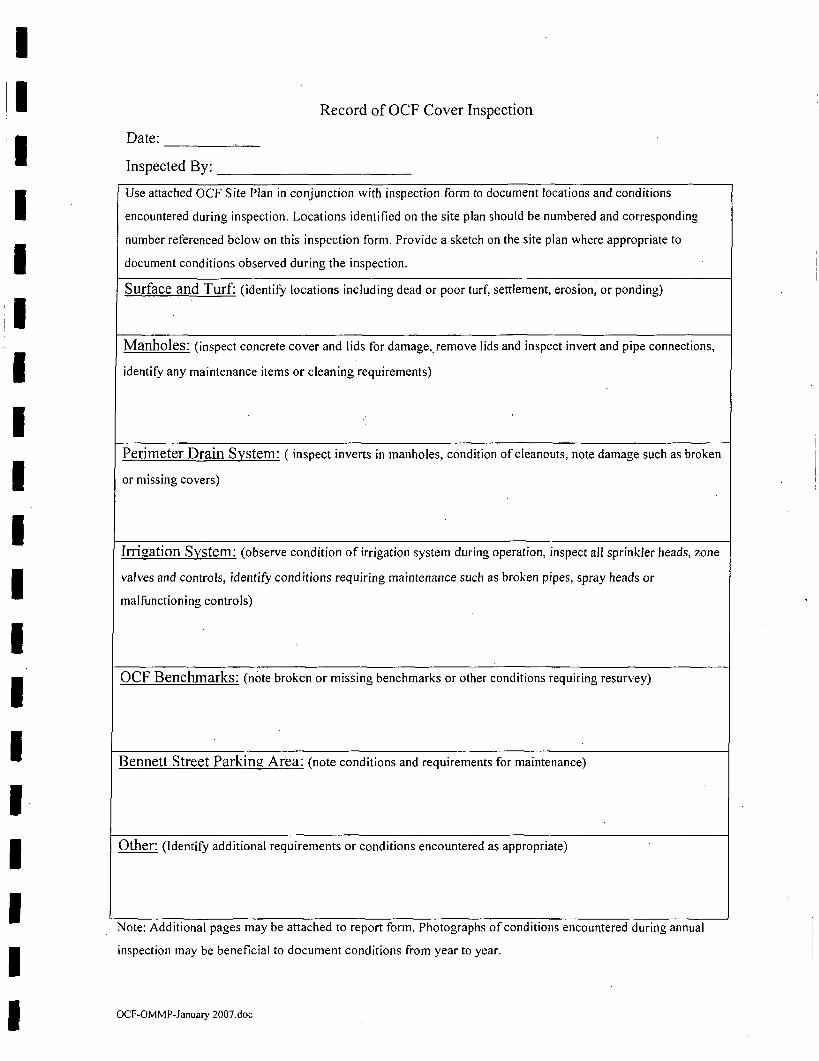
I I I II
I I
'I I I I I I I I I I I I I I
Record of OCF Cover Inspection
Date: ----~--Inspected By: __________ _
Use attached OCF Site Plan in conjunction with inspection form to document locations and conditions
encountered during inspection. Locations identified on the site plan should be numbered and corresponding
number referenced below on this inspection form. Provide a sketch on the site plan where appropriate to
document conditions observed during the inspection.
Surface and Turf: (identify locations including dead or poor turf, settlement, erosion; or ponding)
Manholes: (inspect concrete cover and lids for damage,.remove lids and inspect invert and pipe connections,
identify any maintenance items or cleaning requirements)
Perimeter Drain System: ( inspect inverts in manholes, condition of cleanouts, note damage such as broken
or missing covers)
Irrigation System: (observe condition of irrigation system during operation, inspect all sprinkler heads, zone
valves and controls, identify conditions requiring maintenance such as broken pipes, spray heads or
malfunctioning controls)
OCF Benchmarks: (note broken or missing benchmarks or other conditions requiring resurvey)
Bennett Street Parking Area: (note conditions and requirements for maintenance)
Other: (Identify additional requirements or conditions encountered as appropriate)
Note: Additional pages may be attached to report form. Photographs of conditions encountered during annual
inspection may be beneficial to document conditions from year to year.
OCF-OMMP-January 2007.doc
Related Documents


