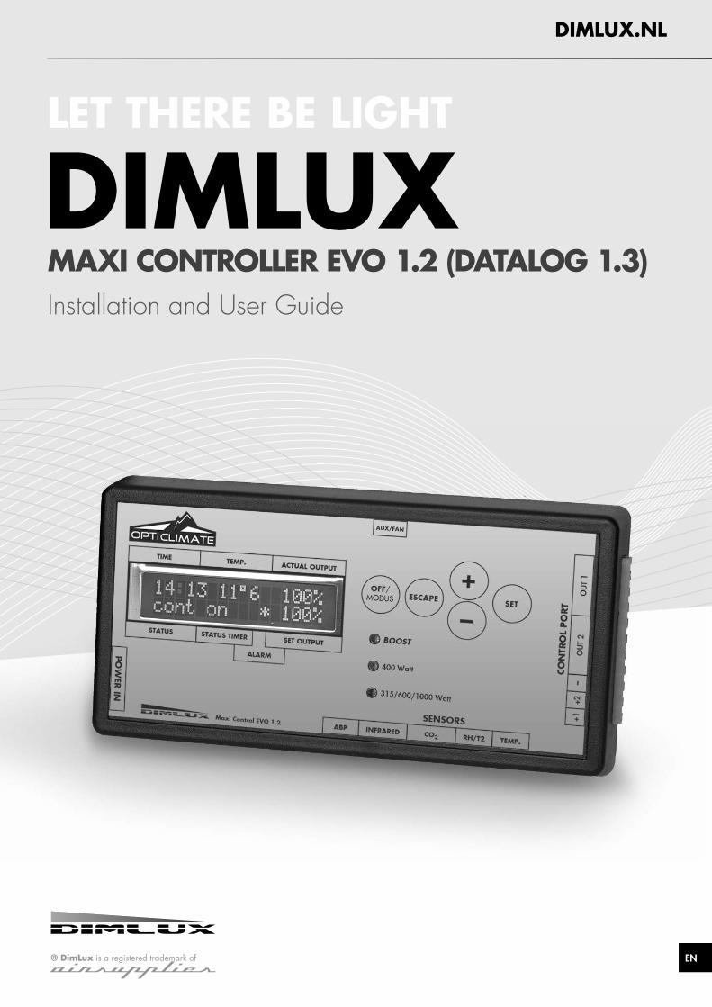
EN LET THERE BE LIGHT DIMLUX DIMLUX.NL ® DimLux is a registered trademark of airSupplies MAXI CONTROLLER EVO 1.2 (DATALOG 1.3) Installation and User Guide

Welcome message from author
This document is posted to help you gain knowledge. Please leave a comment to let me know what you think about it! Share it to your friends and learn new things together.
Transcript
EN
LET THERE BE LIGHT
DIMLUX
DIMLUX.NL
® DimLux is a registered trademark ofairSupplies
MAXI CONTROLLER EVO 1.2 (DATALOG 1.3) Installation and User Guide
2 3
ENEN
INTRODUCTION INSTALLATION
The Dimlux maxi controller is a modular control system for operating and monitoring the Dimlux lighting, CO2 and VPD. The EVO controller is available with and without USB log function. The controller also has a thermostat/hygrostat function (AUX) and can also control a fan.
A maximum of 160 Dimlux light fixtures or pre-selector devices can be controlled by means of two out-ports. The controller switches the lighting on or off by means of a built-in timer. If a set temperature is exceeded, the lighting dims automatically or – if necessary – switches half or all light fixtures off. A switchboard with timer/relay/reducers is not necessary.
Besides lighting, the controller can also regulate the CO2 level in an air-conditioned room. A very accurate dual-beam CO2 sensor can be used to control CO2 generators, cold CO2 installations and ventilation systems for air replacement.
On the AUX port of the EVO 1.2, an “auxbox” can be used to connect a humidifier or a dehumidifier, a heating system and even a ventilator. Various parameters can be read and regulated in a VPD environment. The screen shows the ambient temperature, relative humidity, plant temperature and VPD. The DATALOG function can be used to store all values on a USB stick. The controller writes all measured values onto the stick every minute and these can be read off later in graphic form on a PC.
The controller can also operate the lighting in two rooms in turns. This requires a second temperature sensor, which can be connected to port RH/T2. The relative humidity sensor will no longer be required. The controller is modular: All sensors can be purchased independently according to need.
Components
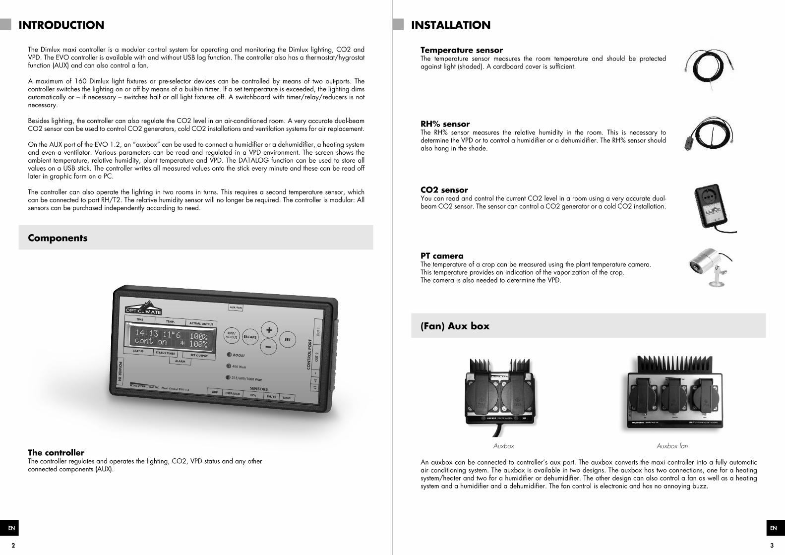
The controllerThe controller regulates and operates the lighting, CO2, VPD status and any otherconnected components (AUX).
Temperature sensorThe temperature sensor measures the room temperature and should be protected against light (shaded). A cardboard cover is sufficient.
RH% sensorThe RH% sensor measures the relative humidity in the room. This is necessary to determine the VPD or to control a humidifier or a dehumidifier. The RH% sensor should also hang in the shade.
CO2 sensorYou can read and control the current CO2 level in a room using a very accurate dual-beam CO2 sensor. The sensor can control a CO2 generator or a cold CO2 installation.
PT cameraThe temperature of a crop can be measured using the plant temperature camera. This temperature provides an indication of the vaporization of the crop. The camera is also needed to determine the VPD.
(Fan) Aux box
Auxbox Auxbox fan
An auxbox can be connected to controller’s aux port. The auxbox converts the maxi controller into a fully automatic air conditioning system. The auxbox is available in two designs. The auxbox has two connections, one for a heating system/heater and two for a humidifier or dehumidifier. The other design can also control a fan as well as a heating system and a humidifier and a dehumidifier. The fan control is electronic and has no annoying buzz.
4 5
ENEN
CONNECTIONS CONNECTIONS & MENU
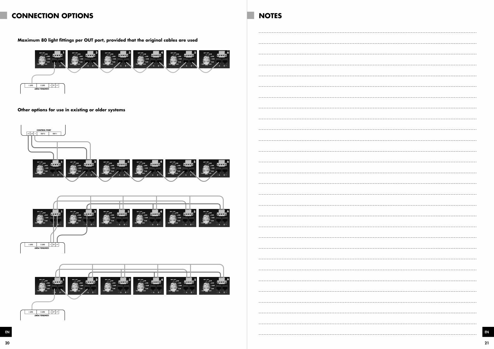
Connecting the lighting ( Also see the other connectivity options on pages 19 & 20 )
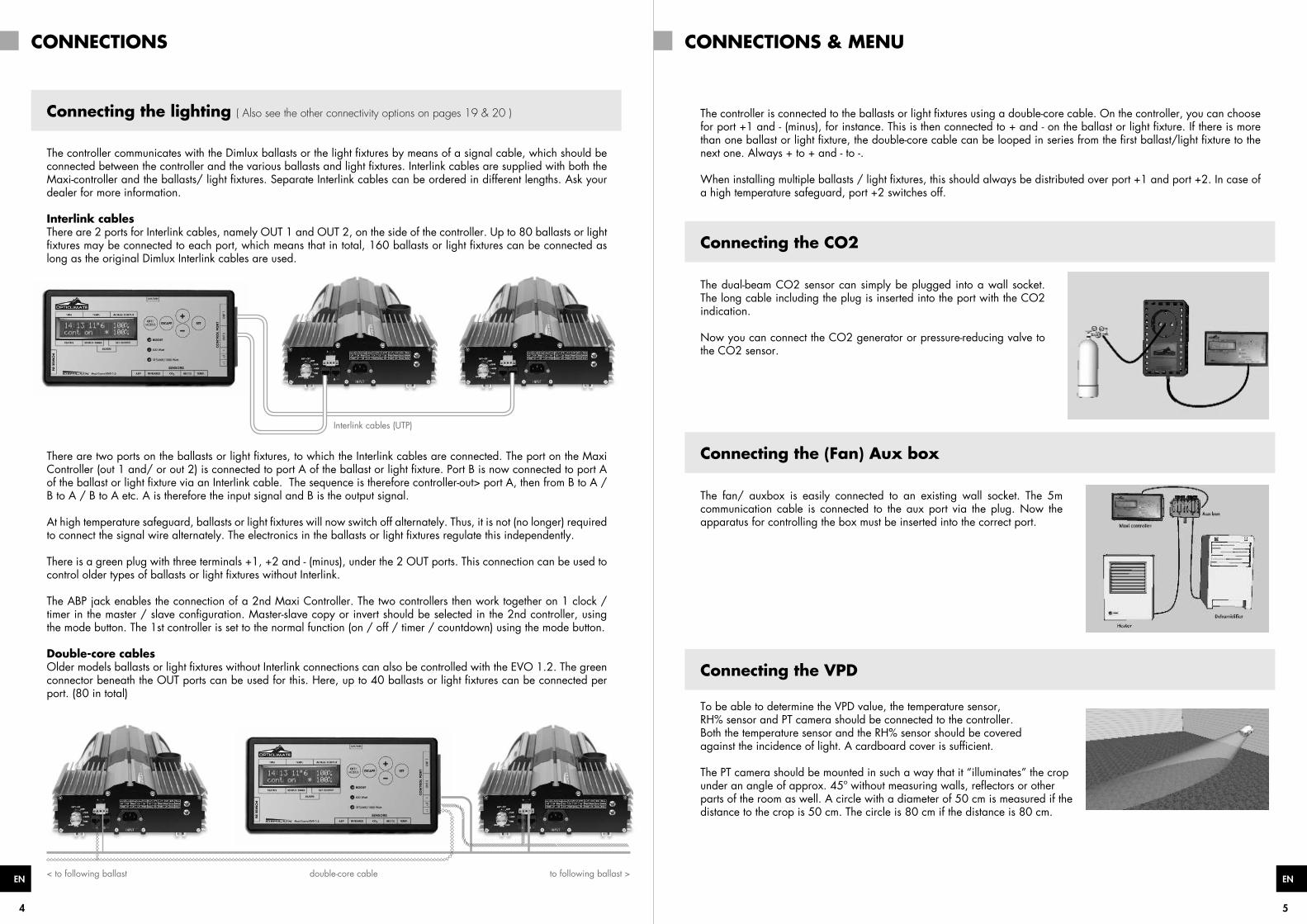
The controller communicates with the Dimlux ballasts or the light fixtures by means of a signal cable, which should be connected between the controller and the various ballasts and light fixtures. Interlink cables are supplied with both the Maxi-controller and the ballasts/ light fixtures. Separate Interlink cables can be ordered in different lengths. Ask your dealer for more information.
Interlink cablesThere are 2 ports for Interlink cables, namely OUT 1 and OUT 2, on the side of the controller. Up to 80 ballasts or light fixtures may be connected to each port, which means that in total, 160 ballasts or light fixtures can be connected as long as the original Dimlux Interlink cables are used.
Interlink cables (UTP)
There are two ports on the ballasts or light fixtures, to which the Interlink cables are connected. The port on the Maxi Controller (out 1 and/ or out 2) is connected to port A of the ballast or light fixture. Port B is now connected to port A of the ballast or light fixture via an Interlink cable. The sequence is therefore controller-out> port A, then from B to A / B to A / B to A etc. A is therefore the input signal and B is the output signal.
At high temperature safeguard, ballasts or light fixtures will now switch off alternately. Thus, it is not (no longer) required to connect the signal wire alternately. The electronics in the ballasts or light fixtures regulate this independently.
There is a green plug with three terminals +1, +2 and - (minus), under the 2 OUT ports. This connection can be used to control older types of ballasts or light fixtures without Interlink.
The ABP jack enables the connection of a 2nd Maxi Controller. The two controllers then work together on 1 clock / timer in the master / slave configuration. Master-slave copy or invert should be selected in the 2nd controller, using the mode button. The 1st controller is set to the normal function (on / off / timer / countdown) using the mode button.
Double-core cablesOlder models ballasts or light fixtures without Interlink connections can also be controlled with the EVO 1.2. The green connector beneath the OUT ports can be used for this. Here, up to 40 ballasts or light fixtures can be connected per port. (80 in total)
double-core cable to following ballast >< to following ballast
The controller is connected to the ballasts or light fixtures using a double-core cable. On the controller, you can choose for port +1 and - (minus), for instance. This is then connected to + and - on the ballast or light fixture. If there is more than one ballast or light fixture, the double-core cable can be looped in series from the first ballast/light fixture to the next one. Always + to + and - to -.
When installing multiple ballasts / light fixtures, this should always be distributed over port +1 and port +2. In case of a high temperature safeguard, port +2 switches off.
Connecting the CO2
The dual-beam CO2 sensor can simply be plugged into a wall socket. The long cable including the plug is inserted into the port with the CO2 indication.
Now you can connect the CO2 generator or pressure-reducing valve to the CO2 sensor.
Connecting the (Fan) Aux box
The fan/ auxbox is easily connected to an existing wall socket. The 5m communication cable is connected to the aux port via the plug. Now the apparatus for controlling the box must be inserted into the correct port.
Connecting the VPD
To be able to determine the VPD value, the temperature sensor, RH% sensor and PT camera should be connected to the controller. Both the temperature sensor and the RH% sensor should be coveredagainst the incidence of light. A cardboard cover is sufficient.
The PT camera should be mounted in such a way that it “illuminates” the crop under an angle of approx. 45º without measuring walls, reflectors or other parts of the room as well. A circle with a diameter of 50 cm is measured if the distance to the crop is 50 cm. The circle is 80 cm if the distance is 80 cm.
6 7
ENEN
MENU & KEYS MENU & KEYS
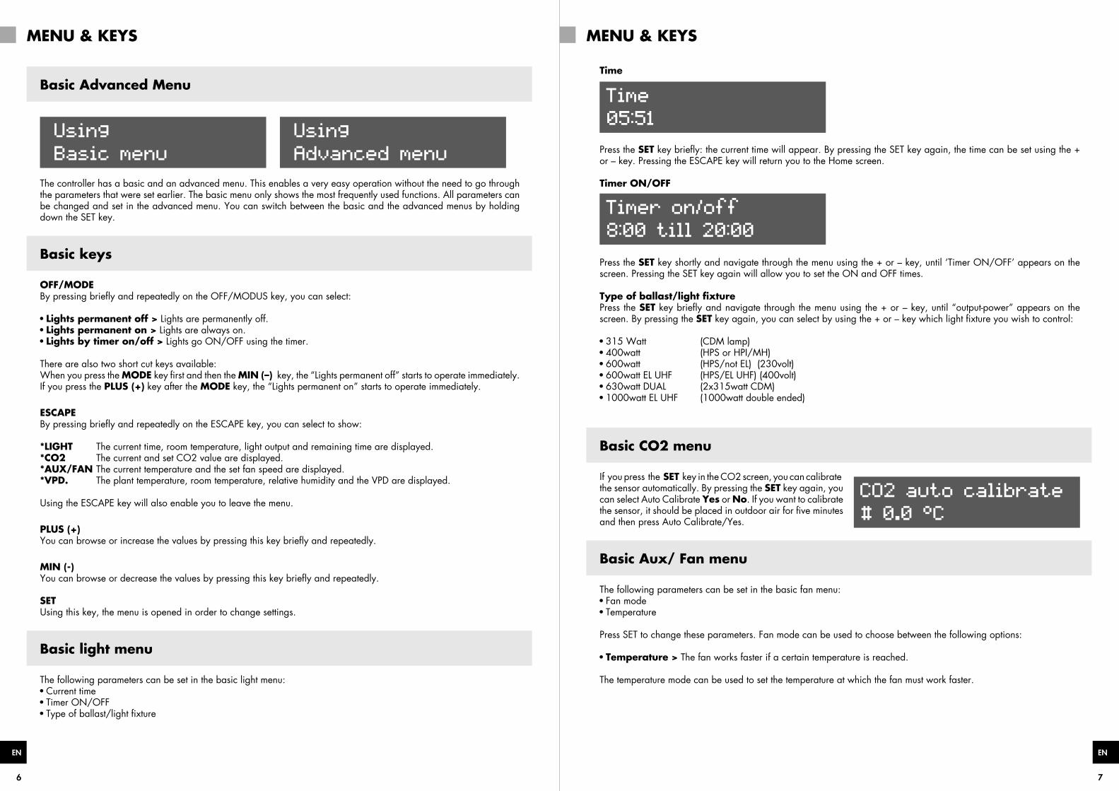
Basic Advanced Menu
Using
Advanced menu
Using
Basic menu
The controller has a basic and an advanced menu. This enables a very easy operation without the need to go through the parameters that were set earlier. The basic menu only shows the most frequently used functions. All parameters can be changed and set in the advanced menu. You can switch between the basic and the advanced menus by holding down the SET key.
Basic keys
OFF/MODEBy pressing briefly and repeatedly on the OFF/MODUS key, you can select:
Lights permanent off > Lights are permanently off. Lights permanent on > Lights are always on. Lights by timer on/off > Lights go ON/OFF using the timer.
There are also two short cut keys available:When you press the MODE key first and then the MIN (–) key, the “Lights permanent off” starts to operate immediately. If you press the PLUS (+) key after the MODE key, the “Lights permanent on” starts to operate immediately.
ESCAPEBy pressing briefly and repeatedly on the ESCAPE key, you can select to show:
*LIGHT The current time, room temperature, light output and remaining time are displayed.*CO2 The current and set CO2 value are displayed.*AUX/FAN The current temperature and the set fan speed are displayed.*VPD. The plant temperature, room temperature, relative humidity and the VPD are displayed.
Using the ESCAPE key will also enable you to leave the menu.
PLUS (+)You can browse or increase the values by pressing this key briefly and repeatedly.
MIN (-)You can browse or decrease the values by pressing this key briefly and repeatedly.
SETUsing this key, the menu is opened in order to change settings.
Basic light menu
The following parameters can be set in the basic light menu: Current time Timer ON/OFF Type of ballast/light fixture
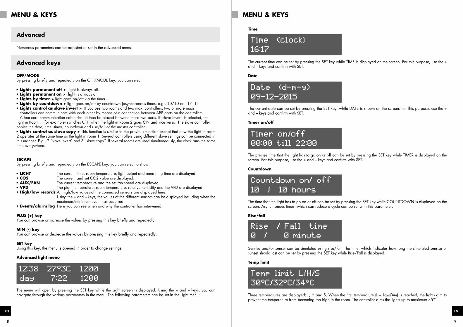
Time
Time
05:51
Press the SET key briefly: the current time will appear. By pressing the SET key again, the time can be set using the + or – key. Pressing the ESCAPE key will return you to the Home screen.
Timer ON/OFF
Timer on/off
8:00 till 20:00
Press the SET key shortly and navigate through the menu using the + or – key, until ‘Timer ON/OFF’ appears on the screen. Pressing the SET key again will allow you to set the ON and OFF times.
Type of ballast/light fixturePress the SET key briefly and navigate through the menu using the + or – key, until “output-power” appears on the screen. By pressing the SET key again, you can select by using the + or – key which light fixture you wish to control:
315 Watt (CDM lamp) 400watt (HPS or HPI/MH) 600watt (HPS/not EL) (230volt) 600watt EL UHF (HPS/EL UHF) (400volt) 630watt DUAL (2x315watt CDM) 1000watt EL UHF (1000watt double ended)
Basic CO2 menu
If you press the SET key in the CO2 screen, you can calibrate
CO2 auto calibrate
# 0.0 °C
the sensor automatically. By pressing the SET key again, you can select Auto Calibrate Yes or No. If you want to calibrate the sensor, it should be placed in outdoor air for five minutes and then press Auto Calibrate/Yes.
Basic Aux/ Fan menu
The following parameters can be set in the basic fan menu: Fan mode Temperature
Press SET to change these parameters. Fan mode can be used to choose between the following options:
Temperature > The fan works faster if a certain temperature is reached.
The temperature mode can be used to set the temperature at which the fan must work faster.
8 9
ENEN
MENU & KEYS MENU & KEYS
Advanced
Numerous parameters can be adjusted or set in the advanced menu.
Advanced keys
OFF/MODEBy pressing briefly and repeatedly on the OFF/MODE key, you can select:
Lights permanent off > light is always off. Lights permanent on > light is always on. Lights by timer > light goes on/off via the timer. Lights by countdown > light goes on/off by countdown (asynchronous times, e.g., 10/10 or 11/11) Lights control as slave invert > If you use two rooms and two maxi controllers, two or more maxi
controllers can communicate with each other by means of a connection between ABP ports on the controllers. A four-core communication cable should then be placed between these two ports. If ‘slave invert’ is selected, the light in Room 1 (for example) switches OFF when the light in Room 2 goes ON and vice versa. The slave controller copies the date, time, timer, countdown and rise/fall of the master controller. Lights control as slave copy > This function is similar to the previous function except that now the light in room
2 operates at the same time as the light in room 1. Several controllers using different slave settings can be connected in this manner. E.g., 2 “slave invert” and 3 “slave copy”. If several rooms are used simultaneously, the clock runs the same time everywhere.
ESCAPEBy pressing briefly and repeatedly on the ESCAPE key, you can select to show:
LICHT The current time, room temperature, light output and remaining time are displayed. CO2 The current and set CO2 value are displayed. AUX/FAN The current temperature and the set fan speed are displayed. VPD The plant temperature, room temperature, relative humidity and the VPD are displayed. High/low records All high/low values of the connected sensors are displayed here.
Using the + and – keys, the values of the different sensors can be displayed including when the maximum/minimum event has occurred. Events/alarm log Here you can see when and why the controller has intervened.
PLUS (+) keyYou can browse or increase the values by pressing this key briefly and repeatedly.
MIN (-) keyYou can browse or decrease the values by pressing this key briefly and repeatedly.
SET keyUsing this key, the menu is opened in order to change settings.
Advanced light menu
12:38 27°3C 1200
day 7:22 1200
The menu will open by pressing the SET key while the Light screen is displayed. Using the + and – keys, you can navigate through the various parameters in the menu. The following parameters can be set in the Light menu:
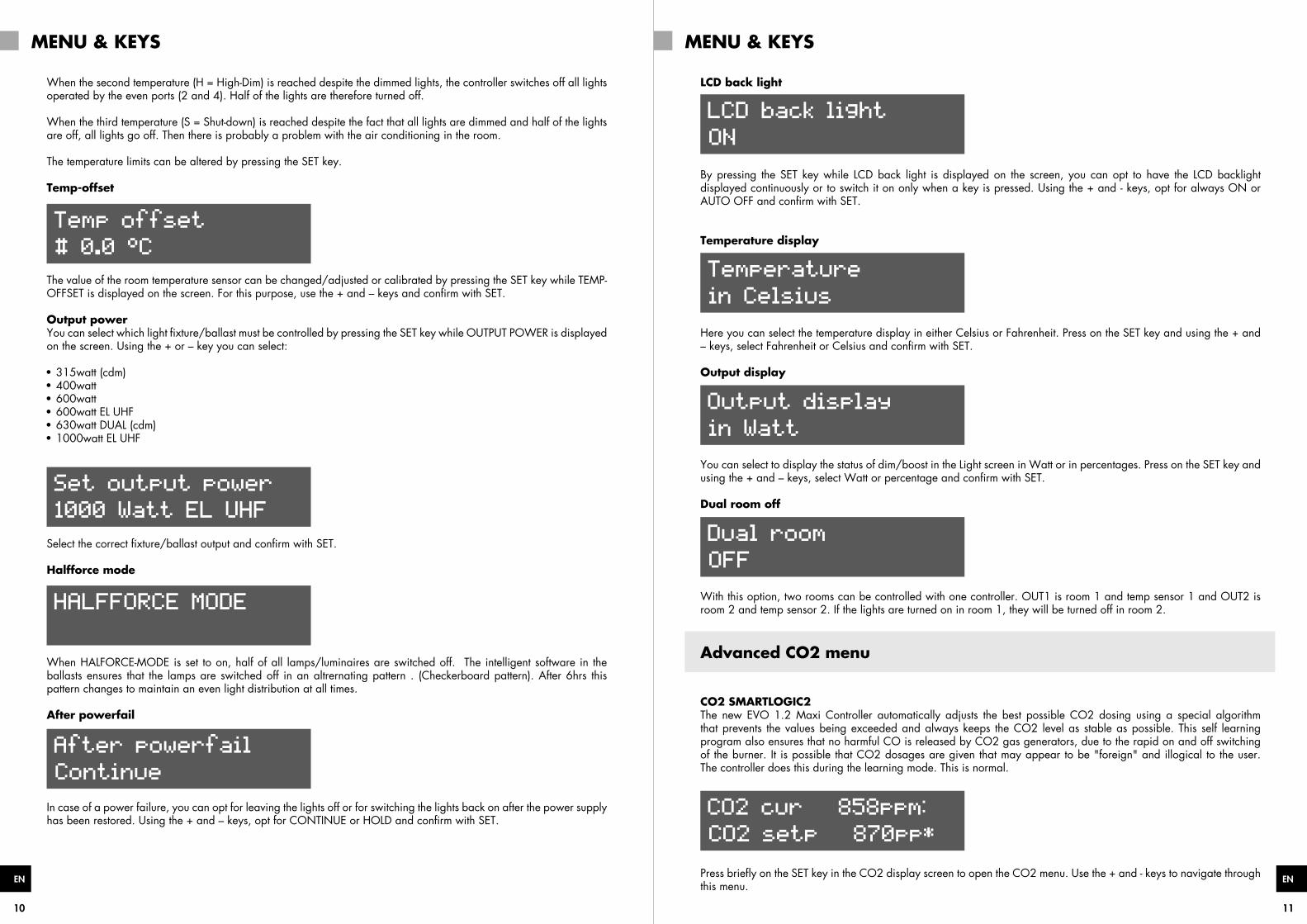
Time
Time (clock)
16:17
The current time can be set by pressing the SET key while TIME is displayed on the screen. For this purpose, use the + and – keys and confirm with SET.
Date
Date (d-m-y)
09-12-2015
The current date can be set by pressing the SET key, while DATE is shown on the screen. For this purpose, use the + and – keys and confirm with SET.
Timer on/off
Timer on/off
00:00 till 22:00
The precise time that the light has to go on or off can be set by pressing the SET key while TIMER is displayed on the screen. For this purpose, use the + and – keys and confirm with SET.
Countdown
Countdown on/ off
10 / 10 hours
The time that the light has to go on or off can be set by pressing the SET key while COUNTDOWN is displayed on the screen. Asynchronous times, which can reduce a cycle can be set with this parameter.
Rise/fall
Rise / Fall time
0 / 0 minute
Sunrise and/or sunset can be simulated using rise/fall. The time, which indicates how long the simulated sunrise or sunset should last can be set by pressing the SET key while Rise/Fall is displayed.
Temp limit
Temp limit L/H/S
30°C/32°C/34°C
Three temperatures are displayed: L, H and S. When the first temperature (L = Low-Dim) is reached, the lights dim to prevent the temperature from becoming too high in the room. The controller dims the lights up to maximum 35%.
10 11
ENEN
MENU & KEYS MENU & KEYS
When the second temperature (H = High-Dim) is reached despite the dimmed lights, the controller switches off all lights operated by the even ports (2 and 4). Half of the lights are therefore turned off.
When the third temperature (S = Shut-down) is reached despite the fact that all lights are dimmed and half of the lights are off, all lights go off. Then there is probably a problem with the air conditioning in the room.
The temperature limits can be altered by pressing the SET key.
Temp-offset
Temp offset
# 0.0 °C
The value of the room temperature sensor can be changed/adjusted or calibrated by pressing the SET key while TEMP-OFFSET is displayed on the screen. For this purpose, use the + and – keys and confirm with SET.
Output powerYou can select which light fixture/ballast must be controlled by pressing the SET key while OUTPUT POWER is displayed on the screen. Using the + or – key you can select:
315watt (cdm) 400watt 600watt 600watt EL UHF 630watt DUAL (cdm) 1000watt EL UHF
Set output power
1000 Watt EL UHF
Select the correct fixture/ballast output and confirm with SET.
Halfforce mode
HALFFORCE MODE
When HALFORCE-MODE is set to on, half of all lamps/luminaires are switched off. The intelligent software in the ballasts ensures that the lamps are switched off in an altrernating pattern . (Checkerboard pattern). After 6hrs this pattern changes to maintain an even light distribution at all times.
After powerfail
After powerfail
Continue
In case of a power failure, you can opt for leaving the lights off or for switching the lights back on after the power supply has been restored. Using the + and – keys, opt for CONTINUE or HOLD and confirm with SET.
LCD back light
LCD back light
ON
By pressing the SET key while LCD back light is displayed on the screen, you can opt to have the LCD backlight displayed continuously or to switch it on only when a key is pressed. Using the + and - keys, opt for always ON or AUTO OFF and confirm with SET.
Temperature display
Temperature
in Celsius
Here you can select the temperature display in either Celsius or Fahrenheit. Press on the SET key and using the + and – keys, select Fahrenheit or Celsius and confirm with SET.
Output display
Output display
in Watt
You can select to display the status of dim/boost in the Light screen in Watt or in percentages. Press on the SET key and using the + and – keys, select Watt or percentage and confirm with SET.
Dual room off
Dual room
OFF
With this option, two rooms can be controlled with one controller. OUT1 is room 1 and temp sensor 1 and OUT2 is room 2 and temp sensor 2. If the lights are turned on in room 1, they will be turned off in room 2.
Advanced CO2 menu
CO2 SMARTLOGIC2The new EVO 1.2 Maxi Controller automatically adjusts the best possible CO2 dosing using a special algorithm that prevents the values being exceeded and always keeps the CO2 level as stable as possible. This self learning program also ensures that no harmful CO is released by CO2 gas generators, due to the rapid on and off switching of the burner. It is possible that CO2 dosages are given that may appear to be "foreign" and illogical to the user. The controller does this during the learning mode. This is normal.
CO2 cur 858ppm:
CO2 setp 870pp
Press briefly on the SET key in the CO2 display screen to open the CO2 menu. Use the + and - keys to navigate through this menu.
12 13
ENEN
MENU & KEYS MENU & KEYS
Auto calibrate
CO2 auto calibrate
The auto calibrate function sets the value automatically to 400 ppm if the sensor is located in outdoor air. Place the sensor outside in the fresh air for a period of 5 minutes, press on the SET key and select AUTO CALIBRATE Yes or No. Confirm by pressing the SET key.
Manual calibrate
co2 manual calib
0 ppm
You can also select to calibrate the sensor manually.Pressing briefly on the SET key will open the menu. Press the SET key once more when CO2 calibrate is displayed.Here you can adjust the value. If the sensor indicates 440 ppm for example in outdoor air, you calibrate the sensor by filling in –40 ppm using the + and – keys.
CO2 modeYou can opt to add or remove CO2 (air quality in living accommodation).
CO2 Addition is selected if CO2 needs to be added. CO2 Removal is selected if CO2 needs to be removed. This is mandatory in public buildings.
Start dosing time
Start dosing tim
0 minutes
To deal with gas/CO2 more efficiently, you can opt for dosing the CO2 after the lights come on. By pressing the SETkey and using the + and – keys, you can select the interval in minutes between lights on and dosing of CO2.
Stop dosing time
Stop dosing tim
0 minutes
To deal with gas/CO2 more efficiently, you can opt for stopping the CO2 dosing before the lights go off. You can select the interval in minutes between stopping the CO2 dosing and lights off by pressing the SET key.
CO2 night heater
CO2 night heater
setpoint 22°
A room can also be heated by the CO2 generator if the power supply is limited.The night temperature can be set by pressing the SET key.
Take note Ensure sufficient supply of fresh air to the room. Poor burning can cause the release of toxicgases that are harmful to people, animals and plants. The flame must always burn with a blue colour.
Advanced aux/fan menu
Eight parameters can be set in the advanced fan menu in order to ensure that the installation works as efficiently as possible.
Temperature RH Day RH Night Max fan speed Day Max fan speed night Min fan speed Aux setting - Temp Aux setting - RH
Press SET once and use the + and- keys to select the above options.Press SET once more to change these parameters.
The fan mode can be changed by pressing the SET key twice. The fan mode determines when the fan control becomes active. It is possible to choose between the following options:
Temperature > the fan works faster if a pre-set temperature is reached. Temp day/dehumidify night > The fan works faster if a pre-set temperature is reached during the day and during the
night if a pre-set relative humidity is reached. Dehumidify day/night > The fan works faster if a pre-set relative humidity is reached. A different value can be set for
the day than for the night. Manual > the fan is set manually to a set speed. The temperature mode can be used to set the temperature at which the fan must work faster. The RH day mode can be used to set the maximum humidity during the day.
(Only visible if the fan mode dehumidify is selected) The RH night mode can be used to set the maximum humidity during the night.
(Only visible if the fan mode dehumidify is selected) Max speed day can be used to set the maximum fan speed during the day. Max speed night can be used to set the maximum fan speed during the night. The min. speed mode can be used to set the minimum fan speed.
(Some fans or ventilators cannot be dimmed by more than 30%). Always check for a draught and whether the fan is working. The aux settings for temperature The aux settings for relative air humidity
14 15
ENEN
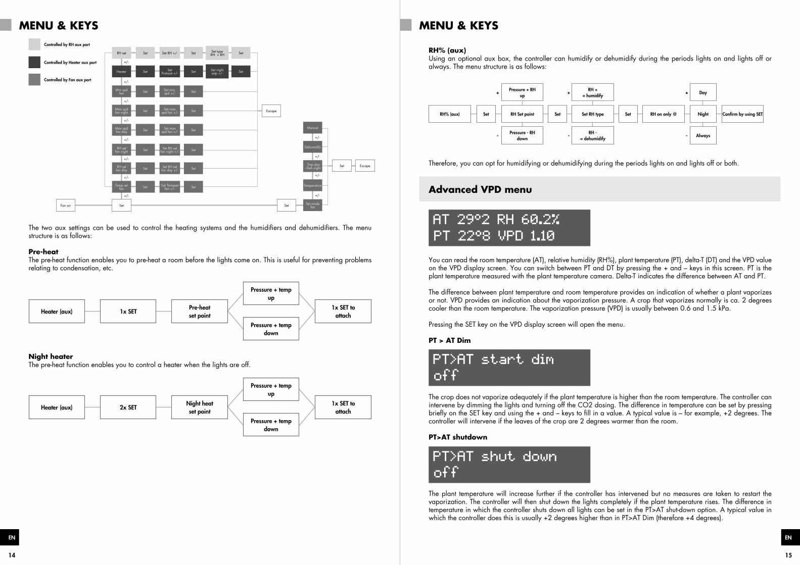
RH set
Min spdfan
Max spdfan night
Max spdfan day
RH set fan night
RH set fan day
Temp set fan
Set Set
Set Escape
Escape
Fan scr
Set
Set
Dehumidify
Manual
Set
- Tmp day- Deh night
Set
Temperature
Set
Set mode fan
Set
Set
Set RH +/-
+/-
+/-
+/-
+/-
+/-
+/-
+/-
+/- +/-
+/-
+/-
+/-
Set min. spd +/-
Set max spd fan +/-
Set max spd fan +/-
Set RH set fan night +/-
Set RH set fan day +/-
Set Tempsetfan +/-
Set
Set
Set
Set
Set
Set
Set
SetSet type-RH + RH
Heater Set Set Preheat +/- Set SetSet night
setp +/-
Controlled by RH aux port
Controlled by Heater aux port
Controlled by Fan aux port
The two aux settings can be used to control the heating systems and the humidifiers and dehumidifiers. The menu structure is as follows:
Pre-heatThe pre-heat function enables you to pre-heat a room before the lights come on. This is useful for preventing problems relating to condensation, etc.
Heater (aux) 1x SETPre-heatset point
Pressure + tempdown
Pressure + tempup
1x SET to attach
Night heaterThe pre-heat function enables you to control a heater when the lights are off.
Heater (aux) 2x SETNight heatset point
Pressure + tempdown
Pressure + tempup
1x SET to attach
MENU & KEYS MENU & KEYS
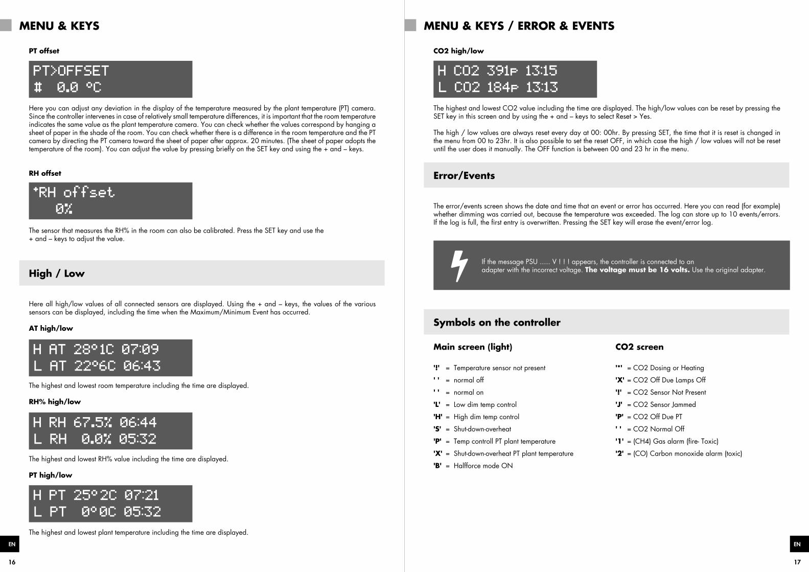
RH% (aux)Using an optional aux box, the controller can humidify or dehumidify during the periods lights on and lights off or always. The menu structure is as follows:
RH% (aux) Set Set SetRH Set point
Pressure + RHup
+ + +
Pressure - RHdown
- - -
Set RH type RH on only @
RH += humidify
RH -= dehumidify
Night
Day
Always
Confirm by using SET
Therefore, you can opt for humidifying or dehumidifying during the periods lights on and lights off or both.
Advanced VPD menu
AT 29°2 RH 60.2%
PT 22°8 VPD 1.10
You can read the room temperature (AT), relative humidity (RH%), plant temperature (PT), delta-T (DT) and the VPD value on the VPD display screen. You can switch between PT and DT by pressing the + and – keys in this screen. PT is the plant temperature measured with the plant temperature camera. Delta-T indicates the difference between AT and PT.
The difference between plant temperature and room temperature provides an indication of whether a plant vaporizes or not. VPD provides an indication about the vaporization pressure. A crop that vaporizes normally is ca. 2 degrees cooler than the room temperature. The vaporization pressure (VPD) is usually between 0.6 and 1.5 kPa.
Pressing the SET key on the VPD display screen will open the menu.
PT > AT Dim
PT>AT start dim
off
The crop does not vaporize adequately if the plant temperature is higher than the room temperature. The controller can intervene by dimming the lights and turning off the CO2 dosing. The difference in temperature can be set by pressing briefly on the SET key and using the + and – keys to fill in a value. A typical value is – for example, +2 degrees. The controller will intervene if the leaves of the crop are 2 degrees warmer than the room.
PT>AT shutdown
PT>AT shut down
off
The plant temperature will increase further if the controller has intervened but no measures are taken to restart the vaporization. The controller will then shut down the lights completely if the plant temperature rises. The difference in temperature in which the controller shuts down all lights can be set in the PT>AT shut-down option. A typical value in which the controller does this is usually +2 degrees higher than in PT>AT Dim (therefore +4 degrees).
16 17
ENEN
PT offset
PT>OFFSET
# 0.0 °C
Here you can adjust any deviation in the display of the temperature measured by the plant temperature (PT) camera. Since the controller intervenes in case of relatively small temperature differences, it is important that the room temperature indicates the same value as the plant temperature camera. You can check whether the values correspond by hanging a sheet of paper in the shade of the room. You can check whether there is a difference in the room temperature and the PT camera by directing the PT camera toward the sheet of paper after approx. 20 minutes. (The sheet of paper adopts thetemperature of the room). You can adjust the value by pressing briefly on the SET key and using the + and – keys.
RH offset
*RH offset
0%
The sensor that measures the RH% in the room can also be calibrated. Press the SET key and use the+ and – keys to adjust the value.
High / Low
Here all high/low values of all connected sensors are displayed. Using the + and – keys, the values of the various sensors can be displayed, including the time when the Maximum/Minimum Event has occurred.
AT high/low
H AT 28° 1C 07:09
L AT 22°6C 06:43
The highest and lowest room temperature including the time are displayed.
RH% high/low
H RH 67.5% 06:44
L RH 0.0% 05:32
The highest and lowest RH% value including the time are displayed.
PT high/low
H PT 25° 2C 07:21
L PT 0° 0C 05:32
The highest and lowest plant temperature including the time are displayed.
MENU & KEYS MENU & KEYS / ERROR & EVENTS
CO2 high/low
H CO2 391p 13:15
L CO2 184p 13:13
The highest and lowest CO2 value including the time are displayed. The high/low values can be reset by pressing the SET key in this screen and by using the + and – keys to select Reset > Yes.
The high / low values are always reset every day at 00: 00hr. By pressing SET, the time that it is reset is changed in the menu from 00 to 23hr. It is also possible to set the reset OFF, in which case the high / low values will not be reset until the user does it manually. The OFF function is between 00 and 23 hr in the menu.
Error/Events
The error/events screen shows the date and time that an event or error has occurred. Here you can read (for example) whether dimming was carried out, because the temperature was exceeded. The log can store up to 10 events/errors. If the log is full, the first entry is overwritten. Pressing the SET key will erase the event/error log.
If the message PSU ..... V ! ! ! appears, the controller is connected to anadapter with the incorrect voltage. The voltage must be 16 volts. Use the original adapter.
Symbols on the controller
Main screen (light) CO2 screen
'!' = Temperature sensor not present '*' = CO2 Dosing or Heating
' ' = normal off 'X' = CO2 Off Due Lamps Off
' ' = normal on '!' = CO2 Sensor Not Present
'L' = Low dim temp control 'J' = CO2 Sensor Jammed
'H' = High dim temp control 'P' = CO2 Off Due PT
'S' = Shut-down-overheat ' ' = CO2 Normal Off
'P' = Temp controll PT plant temperature '1' = (CH4) Gas alarm (fire- Toxic)
'X' = Shut-down-overheat PT plant temperature '2' = (CO) Carbon monoxide alarm (toxic)
'B' = Halfforce mode ON
18 19
ENEN
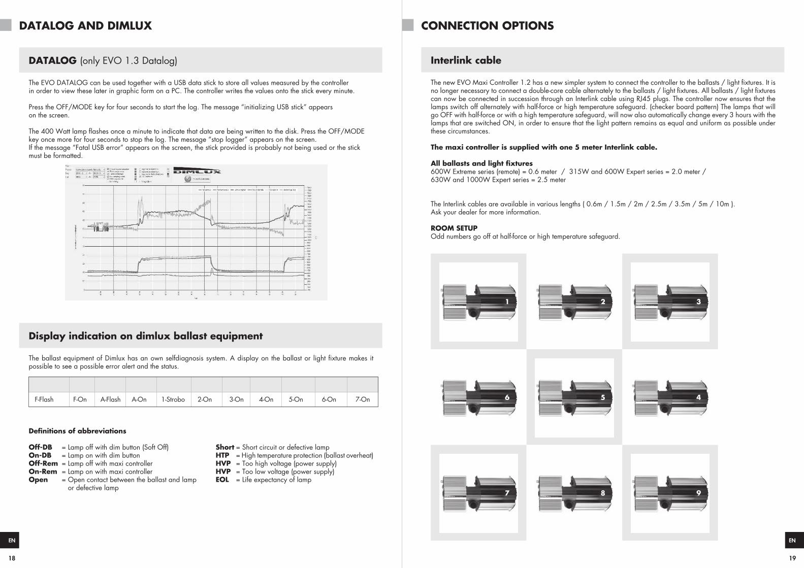
DATALOG (only EVO 1.3 Datalog)
The EVO DATALOG can be used together with a USB data stick to store all values measured by the controllerin order to view these later in graphic form on a PC. The controller writes the values onto the stick every minute.
Press the OFF/MODE key for four seconds to start the log. The message “initializing USB stick” appearson the screen.
key once more for four seconds to stop the log. The message “stop logger” appears on the screen.If the message “Fatal USB error” appears on the screen, the stick provided is probably not being used or the stickmust be formatted.
Display indication on dimlux ballast equipment
The ballast equipment of Dimlux has an own self possible to see a possible error alert and the status.
SOFT-OFF On-DB Off-Rem On-Rem IGNITE HVP LVP HTP Open Short EOL
F-Flash F-On A-Flash A-On 1-Strobo 2-On 3-On 4-On 5-On 6-On 7-On
Off-DB = Lamp off with dim button (Soft Off) Short = Short circuit or defective lampOn-DB = Lamp on with dim button HTP = High temperature protection (ballast overheat)Off-Rem = Lamp off with maxi controller HVP = Too high voltage (power supply)On-Rem = Lamp on with maxi controller HVP = Too low voltage (power supply)Open = Open contact between the ballast and lamp EOL = Life expectancy of lamp or defective lamp
DATALOG AND DIMLUX CONNECTION OPTIONS
Interlink cable
can now be connected in succession through an Interlink cable using RJ45 plugs. The controller now ensures that the lamps switch off alternately with half-force or high temperature safeguard. (checker board pattern) The lamps that will go OFF with half-force or with a high temperature safeguard, will now also automatically change every 3 hours with the lamps that are switched ON, in order to ensure that the light pattern remains as equal and uniform as possible under these circumstances.
The maxi controller is supplied with one 5 meter Interlink cable.
600W Extreme series (remote) = 0.6 meter / 315W and 600W Expert series = 2.0 meter / 630W and 1000W Expert series = 2.5 meter
The Interlink cables are available in various lengths ( 0.6m / 1.5m / 2m / 2.5m / 3.5m / 5m / 10m ). Ask your dealer for more information.
ROOM SETUPOdd numbers go off at half-force or high temperature safeguard.
1
6
7
2
5
8
3
4
9
20 21
ENEN
Maximum 80 light fittings per OUT port, provided that the original cables are used
1 2 3 4 5 6
Other options for use in existing or older systems
1 2 3 4 5 6
1 2 3 4 5 6
1 2 3 4 5 6
CONNECTION OPTIONS NOTES
6
6
6
22 23
ENEN
NOTES NOTES
6
6
Dimlux B.V.Amsterdam, the Netherlands
www.dimlux.nl
MADE IN HOLLAND
® DimLux is a registered trademark of
airSuppliesV101016
Related Documents