NIST Technical Note 1801 Lessons Learned in Establishing the NIST Metal Additive Manufacturing Laboratory Shawn Moylan John Slotwinski April Cooke Kevin Jurrens M. Alkan Donmez

Welcome message from author
This document is posted to help you gain knowledge. Please leave a comment to let me know what you think about it! Share it to your friends and learn new things together.
Transcript

NIST Technical Note 1801
Lessons Learned in Establishing the NIST Metal Additive Manufacturing
Laboratory
Shawn Moylan John Slotwinski
April Cooke Kevin Jurrens
M. Alkan Donmez
karenw
Typewritten Text
http://dx.doi.org/10.6028/NIST.TN.1801

NIST Technical Note 1801
Lessons Learned in Establishing the NIST Metal Additive Manufacturing
Laboratory
Shawn Moylan John Slotwinski
April Cooke Kevin Jurrens
M. Alkan Donmez Intelligent Systems Division
Engineering Laboratory
June 2013
U.S. Department of Commerce Cameron F. Kerry, Acting Secretary
National Institute of Standards and Technology
Patrick D. Gallagher, Under Secretary of Commerce for Standards and Technology and Director
karenw
Typewritten Text
http://dx.doi.org/10.6028/NIST.TN.1801
Certain commercial entities, equipment, or materials may be identified in this
document in order to describe an experimental procedure or concept adequately. Such identification is not intended to imply recommendation or endorsement by the National Institute of Standards and Technology, nor is it intended to imply that the entities, materials, or equipment are necessarily the best available for the purpose.
National Institute of Standards and Technology Technical Note 1801 Natl. Inst. Stand. Technol. Tech. Note 1801, 40 pages (June 2013)
CODEN: NTNOEF
karenw
Typewritten Text
http://dx.doi.org/10.6028/NIST.TN.1801

iii
TABLE OF CONTENTS
1. Introduction ..............................................................................................................1
2. Safety and Environmental Issues .............................................................................2
3. Room Requirements.................................................................................................7
4. Machine Operation...................................................................................................9
5. Materials and Process Parameters ..........................................................................12
6. File Preparation and Support Structures ................................................................13
7. DMLS Design Guidelines ......................................................................................18
8. Post Processing ......................................................................................................23
9. Cost Factors ...........................................................................................................27
10. Conclusions ............................................................................................................27
11. References ..............................................................................................................27
Appendix ................................................................................................................29
ABSTRACT This publication presents a summary of lessons learned by NIST staff during establishment of the NIST Metal Additive Manufacturing Laboratory and implementation of the metal additive manufacturing capability at NIST. These lessons learned resulted from the first implementation of a metal additive manufacturing system at NIST. While the NIST experiences were with a particular metal additive manufacturing system, we believe that these lessons are relevant and have common aspects for implementing other types of metal additive manufacturing systems. The intention is that this summary document will help others to implement metal additive manufacturing capabilities in their facilities. The NIST implementation spanned several months before the system was brought fully online, including facility preparation, system installation, operator training, standard procedure development, and initial experimental use. NIST staff members have been operating the machine for research purposes since early 2011. Parts have been built using metal powders of one stainless steel and one Cobalt-Chrome alloy. These lessons learned address room requirements, safety concerns, machine operation, materials and process parameters, build design file preparation and support structures, design guidelines, and post-processing of manufactured parts.

1
1. INTRODUCTION Additive manufacturing (AM) – also known as direct manufacturing, freeform fabrication, layered manufacturing, and three-dimensional (3D) printing – is defined as the process of joining materials to make objects from 3D model data, usually layer upon layer, as opposed to subtractive manufacturing methodologies such as machining [1]. AM has matured from initial applications in rapid prototyping, where the resulting part was used for form, fit, and/or functional testing, to the making of functional components. AM processes demonstrate significant potential for a revolutionary, rapid, art-to-part capability for making high-value, complex, and individually-customized parts. Additive processes promise the ability to manufacture parts that are difficult or impossible to make with conventional manufacturing techniques, including parts with complex geometries, internal features, engineered porosity, or lattice structures. Companies from a wide variety of industries currently use AM for product development and fabrication, ranging from aerospace parts to biomedical implants to consumer products to maintenance and repair of legacy systems. Broader adoption of AM processes by U.S. manufacturers, however, is currently hindered by deficiencies in part accuracy, surface finish, available materials and material properties, process speed, part size, and standards. The goal of the AM projects in the Engineering Laboratory at the National Institute of Standards and Technology (NIST) is to accelerate the widespread adoption of metal-based additive processes with improved system performance and capability. This will be accomplished through development of a science-based understanding of AM materials and processes via improved measurements, test methods, and standards. The NIST work focuses on metal-based processes because parts produced by these processes are likely to be used as functional components, have a higher inherent value than other materials, and require further improvements (compared to, for example, polymer-based AM processes) before widespread acceptance can be achieved. The current NIST efforts address measurements and standards for the characterization of AM processes and equipment, as well as characterization of the materials used in and resulting from AM processes. The main AM research platform at NIST is the EOSINT1 M270 Dual Mode additive manufacturing system developed by EOS GmbH Electro Optical Systems, hereafter referred to as EOS. This system builds metal parts using a layer-by-layer process called Direct Metal Laser Sintering (DMLS), where the metal powder that defines each successive layer is fused using a high-power laser beam. The metal parts are built on an elevating build platform within a bed of metal powder. The DMLS process is a “powder bed fusion” process as defined by ASTM standard terminology [1]. The Dual Mode designation indicates that the system can operate with two different inert environments within the build chamber to accommodate part fabrication with different types of metal powders. A nitrogen atmosphere within the build chamber is used for fabricating parts from stainless steels, cobalt-chrome alloys, nickel alloys and other metals, while an argon inert atmosphere is necessary for building parts from aluminum alloy or titanium alloy metal powders. While the DMLS system is the main research platform used in the NIST Metal Additive Manufacturing Laboratory, NIST measurement science results are intended to impact the broad
1 EOS®, EOSINT®, and DMLS® are all registered trademarks of EOS GmbH Electro Optical Systems.

2
range of AM systems used by U.S. manufacturers. New test methods and validated models resulting from the NIST efforts are generalized, evaluated by AM experts with other systems, and disseminated to stakeholders through incorporation in documentary standards, primarily through the ASTM F42 committee on Additive Manufacturing Technologies2. The purpose for this publication is to document the lessons learned by NIST during establishment of the NIST Metal Additive Manufacturing Laboratory and implementation of the metal additive manufacturing capability at NIST. The DMLS system was the first metal AM capability implemented at NIST and required repurposing and renovation of an existing manufacturing laboratory space. This document is not a critique of any one system or approach, but identifies considerations that would have common aspects for implementing other types of metal additive systems. The NIST implementation spanned several months before the system was brought fully online, including facility preparation, system installation, operator training, standard operating procedure development, and initial operation. NIST staff have been operating the machine for research purposes since early 2011. Parts have been built using one stainless steel and one Cobalt-Chrome alloy. NIST staff have learned many lessons during this implementation process, and it is hoped that this summary document helps others to implement metal additive manufacturing capabilities in their facilities. 2. SAFETY AND ENVIRONMENTAL ISSUES In the DMLS system, the raw metal powder used as input material, and the ancillary equipment such as the wet-separator (i.e., a special water-filled vacuum system) and filter system all have safety and environmental issues that must be considered as part of standard operations. While these issues require careful planning, development of safety protocols, and diligence in following the safety protocols, it is our experience that they are manageable and reasonable for routine operations of this process. The safety protocols that we have developed and used are for reference only. We do not claim that these are necessarily the best for every user, and different organizations’ safety divisions will have different levels of intensity with respect to designing and approving safety protocols. We welcome any comments or suggestions for improving our safety systems. Risks and Safety Systems Our initial safety concern was the system’s high-powered laser used to fuse the metal powder. The 200 W infrared laser in the machine would normally be classified as Class-IV if it were operated outside of the machine. However, the numerous, redundant safety interlocks, the internal containment of the laser, as well as the infrared-blocking glass window in the build chamber reduces the risk to that of a Class-I laser. The laser will not turn on if the chamber door is open, nor will the laser turn on if the oxygen content within the chamber exceeds 2 %. The manufacturer-recommended safety procedure for checking the door-linked interlock includes disabling the laser by removing the laser fuses (F1 and F2 for the DMLS system). The raw metal powders used as input materials present the greatest risk to operators since they have multiple safety issues associated with them. The metal powders may cause irritation to
2 ASTM F42, http://www.astm.org/COMMITTEE/F42.htm

3
eyes and skin. They are also harmful if inhaled and may cause pulmonary fibrosis. Most metal powders are not considered toxic or classified as carcinogenic, but may cause gastrointestinal effects if ingested and chronic exposure to some metal powders may be implicated in Alzheimer’s disease and pulmonary disease [2]. Metal powders are flammable and potentially explosive, especially when dispersed in a cloud and exposed to an ignition source such as heat or a static electricity spark. Some metal powders burn in the presence of oxidizing substances and certain metal oxides, and some heat spontaneously when moistened with water. The dark vaporized metal powder, termed condensate, that collects on the chamber walls and in the filter unit during a build process is also potentially explosive. The powder inhalation hazard is greatest when loading powder into the machine or manipulating powder inside the build chamber before or after a build. The associated procedures (described later) require the use of a respirator. However, the powder is generally confined to the build chamber, and thus only operators who are working on the parts or powder inside the chamber need to wear the respirator. This guidance is supported by air-borne particulate measurements performed by NIST safety personnel that showed negligible particulates in the room during manipulation of stainless steel powder. Another obvious risk involves the moving systems inside the build chamber. The build platform, the powder dispenser, the powder collector, and the recoating arm are all motor-driven, and thus all present the potential for collisions with other parts of the machine. As an example, the recoating arm could collide with an incorrectly positioned build platform while being moved manually (see Figure 1). Fortunately, the machine’s drive systems are able to detect harsh collisions and stop the motion. Collisions with operators’ hands and arms are generally not an issue, since the motors are disabled while the build chamber door is open.
Figure 1: Components of the build chamber: (a) photograph showing the positions
of the build platform, powder dispenser platform, and recoating blade, and (b) schematic depicting the process of recoating and spreading a new layer of powder
over the previously sintered layers of the part.
Build Platform
Dispenser Platform
Recoating Blade
(a)
Build Platform
Dispenser Platform
Recoating Blade
= Powder= Part= Supports
(b)
4
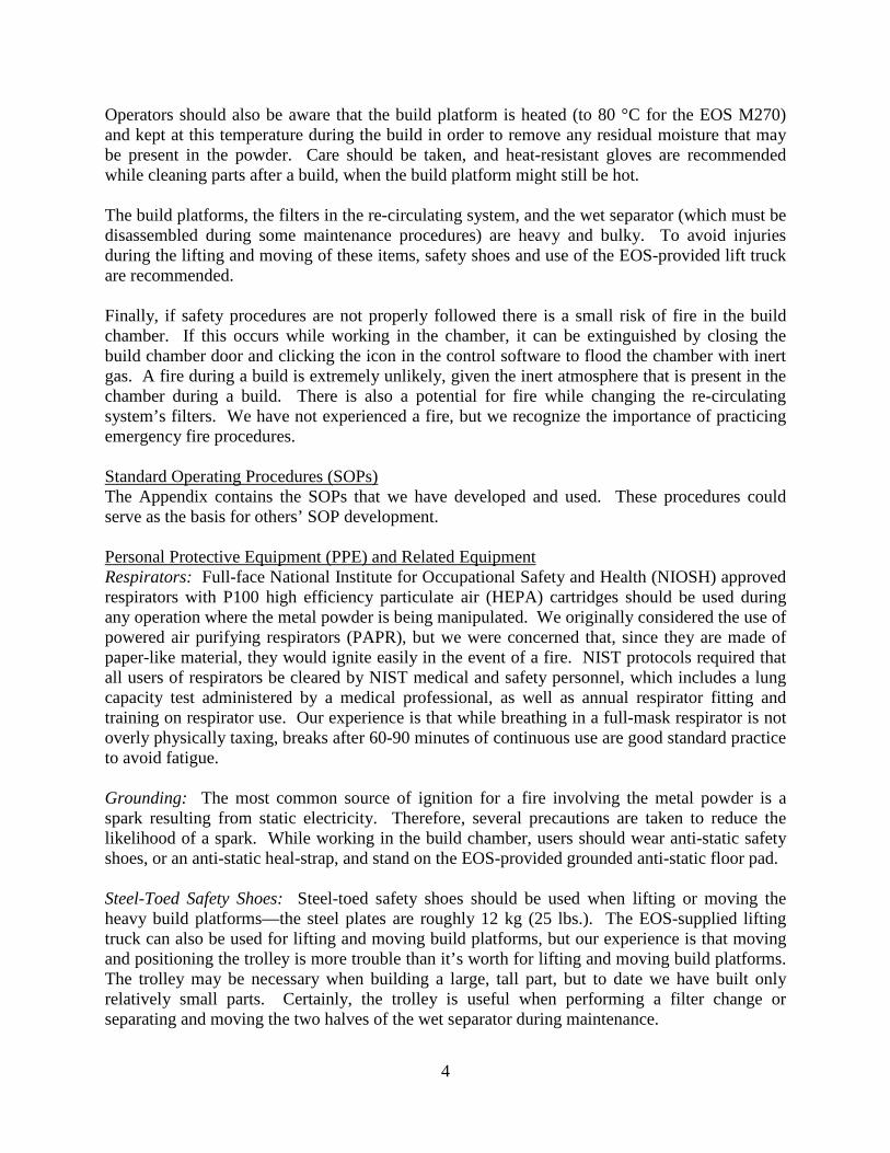
Operators should also be aware that the build platform is heated (to 80 °C for the EOS M270) and kept at this temperature during the build in order to remove any residual moisture that may be present in the powder. Care should be taken, and heat-resistant gloves are recommended while cleaning parts after a build, when the build platform might still be hot. The build platforms, the filters in the re-circulating system, and the wet separator (which must be disassembled during some maintenance procedures) are heavy and bulky. To avoid injuries during the lifting and moving of these items, safety shoes and use of the EOS-provided lift truck are recommended. Finally, if safety procedures are not properly followed there is a small risk of fire in the build chamber. If this occurs while working in the chamber, it can be extinguished by closing the build chamber door and clicking the icon in the control software to flood the chamber with inert gas. A fire during a build is extremely unlikely, given the inert atmosphere that is present in the chamber during a build. There is also a potential for fire while changing the re-circulating system’s filters. We have not experienced a fire, but we recognize the importance of practicing emergency fire procedures. Standard Operating Procedures (SOPs) The Appendix contains the SOPs that we have developed and used. These procedures could serve as the basis for others’ SOP development. Personal Protective Equipment (PPE) and Related Equipment Respirators: Full-face National Institute for Occupational Safety and Health (NIOSH) approved respirators with P100 high efficiency particulate air (HEPA) cartridges should be used during any operation where the metal powder is being manipulated. We originally considered the use of powered air purifying respirators (PAPR), but we were concerned that, since they are made of paper-like material, they would ignite easily in the event of a fire. NIST protocols required that all users of respirators be cleared by NIST medical and safety personnel, which includes a lung capacity test administered by a medical professional, as well as annual respirator fitting and training on respirator use. Our experience is that while breathing in a full-mask respirator is not overly physically taxing, breaks after 60-90 minutes of continuous use are good standard practice to avoid fatigue. Grounding: The most common source of ignition for a fire involving the metal powder is a spark resulting from static electricity. Therefore, several precautions are taken to reduce the likelihood of a spark. While working in the build chamber, users should wear anti-static safety shoes, or an anti-static heal-strap, and stand on the EOS-provided grounded anti-static floor pad. Steel-Toed Safety Shoes: Steel-toed safety shoes should be used when lifting or moving the heavy build platforms—the steel plates are roughly 12 kg (25 lbs.). The EOS-supplied lifting truck can also be used for lifting and moving build platforms, but our experience is that moving and positioning the trolley is more trouble than it’s worth for lifting and moving build platforms. The trolley may be necessary when building a large, tall part, but to date we have built only relatively small parts. Certainly, the trolley is useful when performing a filter change or separating and moving the two halves of the wet separator during maintenance.

5
Gloves: Disposable rubber gloves (e.g., latex), such as non-sterile medical examination gloves, should be used whenever there is a chance of metal powder making contact with the user’s skin. Our experience is that some chemicals (e.g., cleaning agents) may reduce the integrity of this type of glove, so care should be taken to avoid contact with these chemicals. Also, after use, these gloves should be taken off by pulling them inside out, so as to contain any raw powder or powder condensate that may have accumulated on the outside. These gloves do not offer protection from heat, so heat-resistant gloves such as welding gloves should be used when moving warm build platforms. Welding gloves should also be worn in conjunction with other fire-retardant clothing whenever there is greater potential for fire, such as when doing a filter change in the re-circulating unit. Our welding gloves do not allow for the best fine motor control, but we have not yet found suitable fire-retardant gloves that do so. Protective Clothing: For routine build setup and cleaning with the less reactive metal powders, long-sleeved clothing such as a standard lab coat, when used in conjunction with rubber gloves as described above, is sufficient protection against metal powder contacting the user’s skin. Because of the height of the build chamber, and because users must have their arms inside the chamber during setup and cleaning, care must be taken to ensure that powder does not end up on the underside of the user’s arms. This is especially true during a cleaning operation. The wet separator should be used routinely to vacuum protective clothing, just in case any powder has accumulated. For the more reactive powders such as aluminum and titanium, fire-resistant clothing must be used. Fire Resistant Hoods and Clothing: For any work with the more reactive metal powders (i.e., aluminum or titanium alloys), fire resistant clothing must be worn (along with anti-static shoes or the anti-static heal-strap and grounded anti-static floor mat) at all times, including during build setup and cleaning. Fire resistant clothing must also be worn whenever the re-circulating system’s filters are changed, regardless of the type of metal powder used. Our fire resistant clothing are Nomex® jumpsuits, Nomex® hoods, and welder’s gloves. Non-Sparking Tools: Non-sparking tools should be the only tools used to manipulate metal powders. We use the tools supplied by EOS. Wet Separator: We have found the EOS-provided wet separator to be a useful and versatile piece of safety equipment. In addition to cleaning up unrecoverable powder after a build, we use the wet separator to prevent the formation of metal powder clouds whenever powder is manipulated in the build chamber. This is done by holding the vacuum’s nozzle in the build chamber, as shown in Figure 2. Oxygen Sensor: The M270 is equipped with an oxygen sensor that monitors the oxygen level present in its surroundings. When the oxygen level falls below 19 % in the room, a lamp illuminates and instructions from EOS dictate to cut off the argon supply (if it is being used) and to ventilate the room. If the oxygen level falls below 17 %, the same lamp will illuminate and an

6
Figure 2: Wet separator being used to prevent the possible formation
of a metal powder cloud during a build cleanup. alarm will sound. In this situation, instructions from EOS dictate immediate room evacuation. In addition to the oxygen sensor on the DMLS machine, EOS recommends the installation of a stationary oxygen sensor with an alarm function in all rooms where argon could escape in the case of a leak from the supply pipe or the waste gas pipe. The external warning device can be combined with the machine’s room air monitoring system using an interface on the machine. It is possible to close the main argon valve on the machine using an external switching signal. Fire Extinguisher: Only Class-D fire extinguishers should be used on fires that contain metal powders. These extinguishers are large, heavy and bulky, and as such, we do not hang ours on a wall. The extinguisher sits on the floor next to the wall inside our additive manufacturing facility, near the DMLS system. The long hose connecting the extinguisher’s nozzle to the extinguisher itself and the long distance spray capability of the extinguisher mean that it should not need to be moved while being used if it is already reasonably close to the machine and filter system. Chemical Storage Cabinet: Metal powders should always be stored in their original, tightly closed vendor-supplied containers with the desiccant, inside an approved metal, flammable storage cabinet that is cool, dry, and ventilated. This cabinet should protect against physical damage and be isolated from sources of heat, ignition, and moisture. We use a standard metal chemical storage cabinet. Trashcan: Soiled consumables such as rubber gloves and paper towels should be disposed of in a metal, closeable trashcan until they can be disposed of permanently. Disposal of Waste Procedures for the disposal of simple consumables (soiled gloves and paper towels), filters, and powder sludge (from the wet separator) should always follow local and federal laws, as well as the recommendations of company or institute disposal departments. Our experience is that large, thick black plastic trash bags are extremely useful for containing and disposing of this waste.

7
3. ROOM REQUIREMENTS Several facility requirements were identified for implementing the DMLS system in the NIST laboratory. These requirements primarily addressed space needs, floor characteristics, environmental controls, gas cylinder storage and access, and utility connections. Substantial site preparation was required prior to system installation to ensure a suitable and safe facility. Space Needs: The size of the primary DMLS system measures 2.2 m x 1.1 m x 2.3 m. In addition to the machine itself, several auxiliary and accessory components are necessary to operate the DMLS system. These separate components include the electrical transformer, cooling system (chiller) for the laser, re-circulating unit, wet separator (vacuum) system, and lifting truck. Further space is needed for multiple argon gas cylinders, work benches and cabinets for storing build platforms and parts, the computer workstation for preparing part files, a safety cabinet for storing metal powders, an anti-static floor mat for grounding the system operators, and a programmable heat-treat oven and shot peening stations for post-processing the resulting parts. Requirements for cooling airflow in the room dictate minimum spacing between components and away from walls. In order to best contain any stray metal powder and to maintain cleanliness, our laboratory encloses the primary system components and metal powder storage behind a closed door with a glass window (for both visibility and operator safety). The computer workstation is located just outside this space since metal powder dust could damage the computer if not kept clean. Likewise, our oven and shot-peening stations for post-processing are located in an adjacent space outside the main laboratory. While this space is adequate, certainly more space would be desirable, especially when maneuvering the lifting truck, performing a filter change in the re-circulating unit, or servicing the wet separator. Further, we still need to identify a place to house the gas cylinders required for operating with an argon environment. Figure 3 shows a diagram of the room layout for the NIST Metal Additive Manufacturing Laboratory. Floor Characteristics: The floor of the room where the machine is installed can collapse if floor loading exceeds the capacity of the facility. The primary DMLS machine weighs approximately 1250 kg without the metal powder. The metal powder can add up to 130 kg more when at the maximum capacity. The other accessories, equipment, and people in the room further contribute to the floor loading. Since the primary machine stands on four screw feet (with diameter 80 mm), the recommended floor loading capacity for the room is >200 N/cm2. In addition, the floor should be hard, flat, level, and free from interfering vibration caused by other manufacturing equipment, though no specific acceptable vibration levels are specified by the manufacturer. The floor should be easy to clean and suitable for wet cleaning in case of spilled metal powder dust. An electrically conductive floor is preferred to prevent static charge, though an anti-static mat in front of the system can provide a similar capability. Environmental Controls: In general, the room environmental requirements for temperature and humidity are not stringent, though general guidelines must be followed. The primary concern is to control humidity when the metal powder may be exposed. When the DMLS system is not in operation and not filled with metal powder, the permitted room temperature can vary from 10 °C to 40 °C, and the relative humidity can range from 20 % to 80 %. However, when the machine is in an operational status, the permitted room temperature is limited to 20 °C to 25 °C at 60 %

8
Figure 3: Layout of the NIST Metal Additive Manufacturing Laboratory.
relative humidity, and 25 °C to 30 °C at 45 % relative humidity. The metal powders should be stored in their original closed containers with the desiccant whenever possible and kept from temperature and humidity extremes. We have noted that the temperature in our lab increases when the system is operating since the facility door is typically closed. Additional air conditioning may be necessary to maintain comfort levels for the system users. Gas Cylinder Storage and Access: When operating with a nitrogen environment in the build chamber, the DMLS system creates the nitrogen with a generator that is integrated into the machine frame. This system generates the nitrogen from external air. When building parts that require an argon inert environment, a series of multiple argon gas cylinders is typically required to meet the build time requirements. The argon flow rate under normal operating conditions can be up to 100 L/min and typical build times can range from several hours to multiple days. The facility must be configured to accommodate storage of multiple gas cylinders with sufficient access to facilitate replacement of cylinders when empty. Building/Utility Connections: The electrical transformer for the DMLS system must be connected to a separate, three-phase power circuit and must be fused. No large electric motors can be connected to the same circuit. The wet separator (vacuum) system is powered through direct connection to the socket on the rear of the machine with a grounded wire. Compressed dry air connections to the building supply are required for operating the DMLS nitrogen generator
5.3 m
DMLS System
Cooling System
Flammables Storage Cabinet
Wet Separator
Rec
ircu
latin
g U
nit
Transformer
Work Bench and Cabinets
Lifting Truck
Class D Fire Extinguisher
4.1
m
Anti-static mat
9
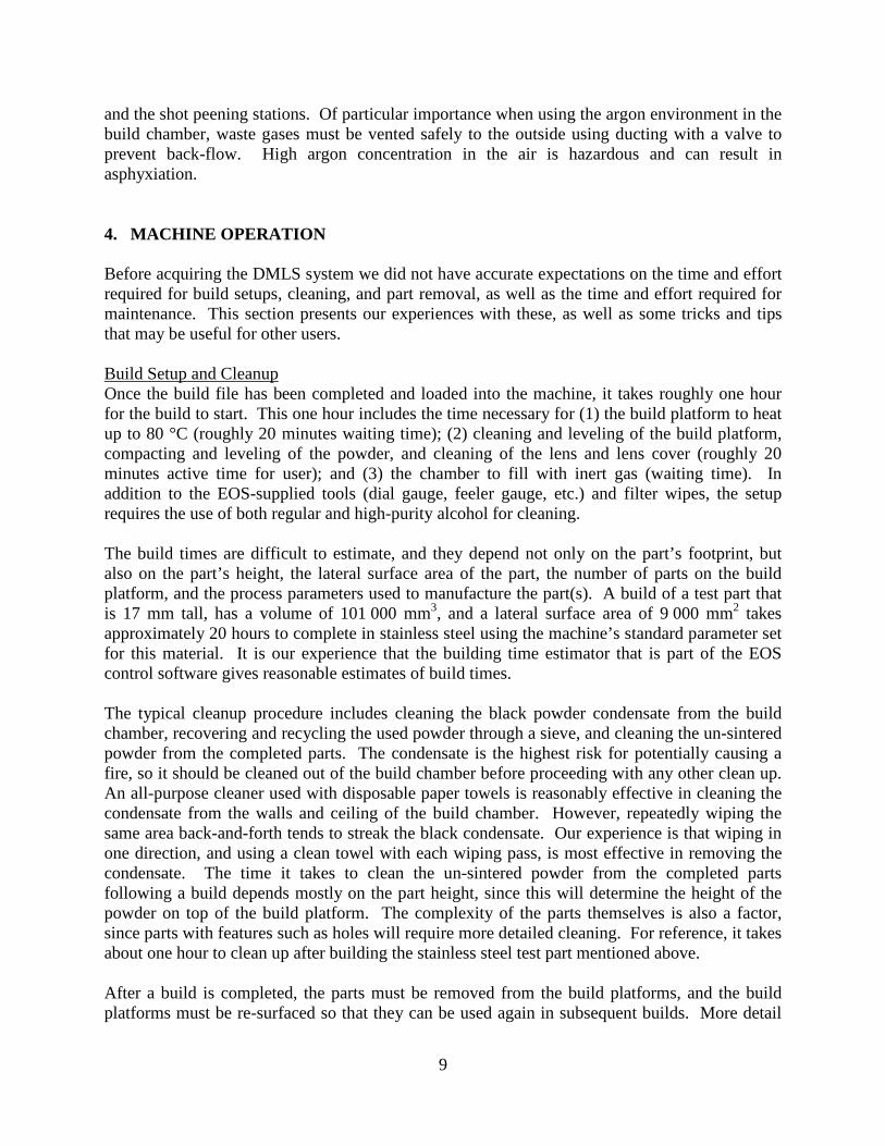
and the shot peening stations. Of particular importance when using the argon environment in the build chamber, waste gases must be vented safely to the outside using ducting with a valve to prevent back-flow. High argon concentration in the air is hazardous and can result in asphyxiation. 4. MACHINE OPERATION Before acquiring the DMLS system we did not have accurate expectations on the time and effort required for build setups, cleaning, and part removal, as well as the time and effort required for maintenance. This section presents our experiences with these, as well as some tricks and tips that may be useful for other users. Build Setup and Cleanup Once the build file has been completed and loaded into the machine, it takes roughly one hour for the build to start. This one hour includes the time necessary for (1) the build platform to heat up to 80 °C (roughly 20 minutes waiting time); (2) cleaning and leveling of the build platform, compacting and leveling of the powder, and cleaning of the lens and lens cover (roughly 20 minutes active time for user); and (3) the chamber to fill with inert gas (waiting time). In addition to the EOS-supplied tools (dial gauge, feeler gauge, etc.) and filter wipes, the setup requires the use of both regular and high-purity alcohol for cleaning. The build times are difficult to estimate, and they depend not only on the part’s footprint, but also on the part’s height, the lateral surface area of the part, the number of parts on the build platform, and the process parameters used to manufacture the part(s). A build of a test part that is 17 mm tall, has a volume of 101 000 mm3, and a lateral surface area of 9 000 mm2 takes approximately 20 hours to complete in stainless steel using the machine’s standard parameter set for this material. It is our experience that the building time estimator that is part of the EOS control software gives reasonable estimates of build times. The typical cleanup procedure includes cleaning the black powder condensate from the build chamber, recovering and recycling the used powder through a sieve, and cleaning the un-sintered powder from the completed parts. The condensate is the highest risk for potentially causing a fire, so it should be cleaned out of the build chamber before proceeding with any other clean up. An all-purpose cleaner used with disposable paper towels is reasonably effective in cleaning the condensate from the walls and ceiling of the build chamber. However, repeatedly wiping the same area back-and-forth tends to streak the black condensate. Our experience is that wiping in one direction, and using a clean towel with each wiping pass, is most effective in removing the condensate. The time it takes to clean the un-sintered powder from the completed parts following a build depends mostly on the part height, since this will determine the height of the powder on top of the build platform. The complexity of the parts themselves is also a factor, since parts with features such as holes will require more detailed cleaning. For reference, it takes about one hour to clean up after building the stainless steel test part mentioned above. After a build is completed, the parts must be removed from the build platforms, and the build platforms must be re-surfaced so that they can be used again in subsequent builds. More detail

10
about refinishing build platforms is provided in a later section. However, it is worth noting that since it takes time for a local shop to perform the required part removal and resurfacing of the build platforms, we have found that it is practical to have a large number of build platforms, so that some are always available while others are in the queue to have parts removed or be refinished. Maintenance EOS provides a scheduled listing of required maintenance for the M270 machine. Several maintenance items need to be completed before each build, others are daily, weekly, or monthly. Since our machine is typically not running continuously (thus far we typically do a few builds per month), we generally do all of the non-monthly maintenance items before each build. We designate one Friday each month to handle the monthly items, and these generally take 1-3 hours, depending on what needs to be done. Below we highlight a few items of note based on our experiences; this list should not be considered an exhaustive discussion of the required maintenance. Machine: We check the recoating blade about monthly, or any time after we have observed significant grinding or harsh rubbing against the in-process part (easily identified audibly) during a build. Discolorations on the blade do not necessarily mean that the blade is worn enough to warrant replacement. We have found that it is best to look for blade wear under a microscope or magnifying glass. The blade should be inspected both head-on (looking at the front and back faces of the blade) and along the profile (looking down the edge). Grounding Mat: Checking the electrical connection on the grounding mat is not an item included in the EOS-recommended maintenance. However, because of an early failure in our pad’s grounding wire, we now routinely check the conductance of the mat to the machine by using a digital multi-meter to measure the resistance between the pad’s grounding wire grommet and a metal bolt under the machine’s top cover. The resistance should read slightly greater than 1 MΩ. Note that typically the continuity function of a multi-meter will read no-continuity for this resistance, which is why we perform a resistance measurement instead. Filter System: The machine’s control software will indicate when a filter change is required. The dial gauge on the right side of the filter system can also be used to decide when to change the filter. If this gauge reads close to 2.0, then it is time to make a change. Through approximately 270 hours of use, we needed two filter changes. Filter changes are likely the most potentially dangerous aspect of the DMLS system due to the fire potential of the powder condensate that is captured in the filters. The EOS-recommended procedures and PPE should be followed explicitly. The thick-fingered welding gloves that we wear during this operation make it difficult to detach and re-attach the grounding wire in the filter system, but as of yet we have not found a suitable alternative glove. We do all filter changes with two people and do not allow others in the room while this is being done. It takes roughly 60 minutes to complete a filter change. Wet Separator: Maintenance on the wet separator also requires two people, and takes roughly 60 minutes to complete. We first use the lifting truck to lift the top section off the bottom section. We then place a thick piece of wood that is longer than the width of the wet separator in-between
11
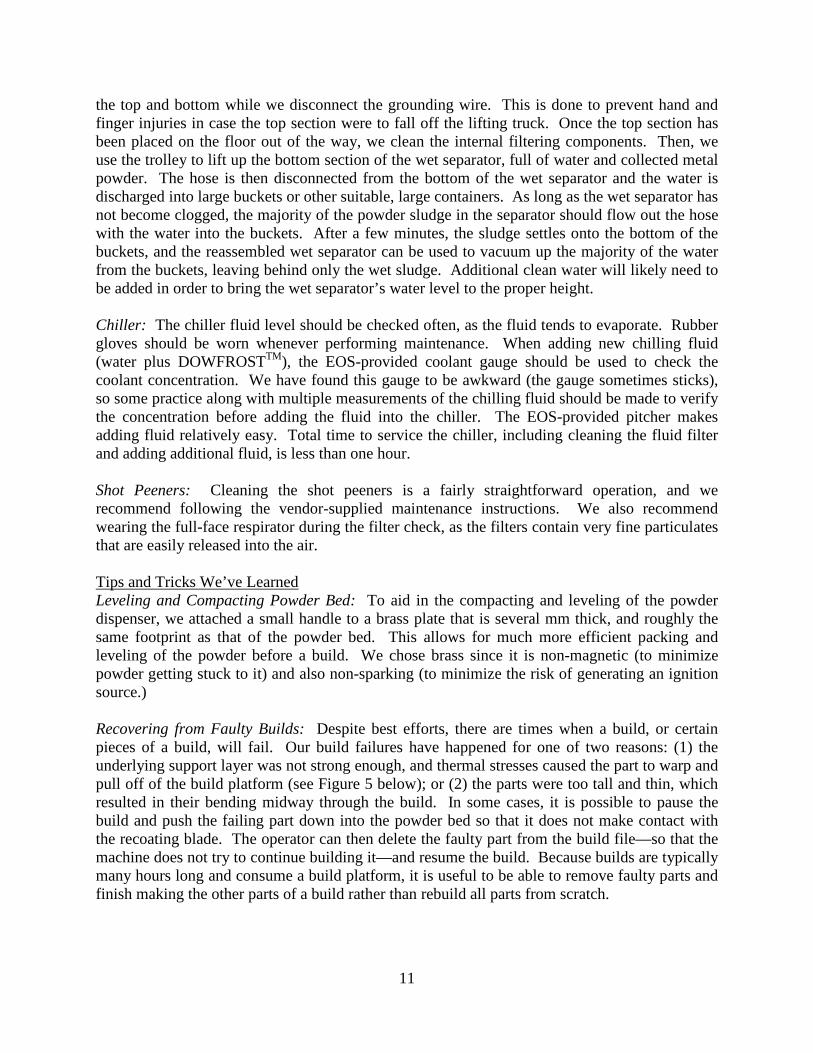
the top and bottom while we disconnect the grounding wire. This is done to prevent hand and finger injuries in case the top section were to fall off the lifting truck. Once the top section has been placed on the floor out of the way, we clean the internal filtering components. Then, we use the trolley to lift up the bottom section of the wet separator, full of water and collected metal powder. The hose is then disconnected from the bottom of the wet separator and the water is discharged into large buckets or other suitable, large containers. As long as the wet separator has not become clogged, the majority of the powder sludge in the separator should flow out the hose with the water into the buckets. After a few minutes, the sludge settles onto the bottom of the buckets, and the reassembled wet separator can be used to vacuum up the majority of the water from the buckets, leaving behind only the wet sludge. Additional clean water will likely need to be added in order to bring the wet separator’s water level to the proper height. Chiller: The chiller fluid level should be checked often, as the fluid tends to evaporate. Rubber gloves should be worn whenever performing maintenance. When adding new chilling fluid (water plus DOWFROSTTM), the EOS-provided coolant gauge should be used to check the coolant concentration. We have found this gauge to be awkward (the gauge sometimes sticks), so some practice along with multiple measurements of the chilling fluid should be made to verify the concentration before adding the fluid into the chiller. The EOS-provided pitcher makes adding fluid relatively easy. Total time to service the chiller, including cleaning the fluid filter and adding additional fluid, is less than one hour. Shot Peeners: Cleaning the shot peeners is a fairly straightforward operation, and we recommend following the vendor-supplied maintenance instructions. We also recommend wearing the full-face respirator during the filter check, as the filters contain very fine particulates that are easily released into the air. Tips and Tricks We’ve Learned Leveling and Compacting Powder Bed: To aid in the compacting and leveling of the powder dispenser, we attached a small handle to a brass plate that is several mm thick, and roughly the same footprint as that of the powder bed. This allows for much more efficient packing and leveling of the powder before a build. We chose brass since it is non-magnetic (to minimize powder getting stuck to it) and also non-sparking (to minimize the risk of generating an ignition source.) Recovering from Faulty Builds: Despite best efforts, there are times when a build, or certain pieces of a build, will fail. Our build failures have happened for one of two reasons: (1) the underlying support layer was not strong enough, and thermal stresses caused the part to warp and pull off of the build platform (see Figure 5 below); or (2) the parts were too tall and thin, which resulted in their bending midway through the build. In some cases, it is possible to pause the build and push the failing part down into the powder bed so that it does not make contact with the recoating blade. The operator can then delete the faulty part from the build file—so that the machine does not try to continue building it—and resume the build. Because builds are typically many hours long and consume a build platform, it is useful to be able to remove faulty parts and finish making the other parts of a build rather than rebuild all parts from scratch.

12
Cleaning and Sieving: After a build, before recycling the unexposed powder by passing it through the EOS-supplied 80 µm sieve that mounts over the dispenser bin, it is a good idea to scrape several millimeters worth of powder from the top of the powder dispenser onto the build platform. The reason for doing this is that residue from the building process (black soot or partially sintered powder) that should be sieved before it is reused is often among the top layer of powder in the dispenser. Manually filtering the powder through the sieve can be a slow, tedious task. However, attaching a low air-pressure (60 psi) pneumatic vibrator to the sieve with magnets automates the process and makes it much less labor intensive. Duct tape on the anodized surfaces that make contact with the sieve prevent the anodized layers from chipping away. Extended Builds: Builds of 200 h to 300 h are frequent in industry and builds lasting longer than 400 hours are not uncommon. It will be necessary to pause these builds part-way through to clean the lens and lens cover because condensate can build up on the lens and prevent the full power of the laser from reaching the part. EOS advised pausing for cleaning for builds lasting longer than 75 h. Because this cleaning requires the opening of the chamber door, the build chamber loses its inert environment (note that care should be taken when opening the door for powder built up on the chamber window and ledge potentially spilling out). Before resuming the building process, the inert atmosphere in the chamber must be re-established. The entire process takes 25 min to 30 min. Because during this time the previously exposed layer is cooling, it is advisable to re-expose the previous layer to return it to temperature before proceeding with the next layer. Regardless of the procedure followed, a witness mark is usually evident on the final part at the height of the pause. The effect on mechanical properties is being investigated. New models of DMLS systems have better laminar flow in the chamber, resulting in less condensate reaching the lens. In addition to cleaning, the build may need to be paused to refill the dispenser bin with powder for extremely tall, large builds. Build Platform Warping: The high rates of heating and cooling during the DMLS process lead to a large amount of thermal stress in the parts. This is especially the case for parts that have a large exposure area. These parts tend to warp, and in extreme cases the thermal stresses may warp the entire build platform. As a result, the bolts holding down the build platform may be under a great amount of pressure and may be very difficult to remove after the build process. It may be necessary to break off a bolt head or drill out the bolts to relieve the pressure and remove the build platform. This phenomenon may be difficult to avoid, but if the bolts are extremely difficult to loosen, each bolt should only be loosened slightly before moving to the next bolt. Fully relieving the stress on one bolt may increase the force on the other bolts, only exacerbating the problem. 5. MATERIALS AND PROCESS PARAMETERS Process Parameters After the DMLS machine was purchased and installed, we quickly learned that we did not have access to all of the machine’s capabilities. We needed to obtain additional license files to allow us to make parts from different species of metal powder, and to adjust process parameters like laser power and laser scanning speed as desired.
13
Building in Different Materials: The DMLS machine can make parts out of several different metal powders, including stainless steels, Cobalt-Chrome alloys, an Aluminum alloy, Titanium alloys, etc., but each material requires the use of different process parameters. Each unique “recipe” consists of the predefined variables and settings for process parameters that have been optimized by EOS for the specific material. While the DMLS machine, as it comes from the manufacturer, already has all of the process parameter recipes necessary for making parts out of each compatible material, in order to access the recipes, licenses must be purchased for each material. These recipes are activated when a license file is added to the software’s dongle. The process of accessing recipes includes creating a license request file on the software’s dongle, sending that request file to the manufacturer along with payment for the specific recipe, and installing the license file for that specific material’s recipe upon receipt of the license file. Developer’s Kit: The version of the DMLS control software that we purchased (PSW 3.5 version 40), in its original state, does not allow the user to see or alter the values of the processing parameters. This may be beneficial to novice users seeking to immediately make parts because the canned “recipes” have been optimized by EOS for each specific material, and users do not need to develop their own recipes. However, since our intentions are research related, the lack of flexibility was limiting. To have control over process parameters, we obtained a Developer’s Kit from the manufacturer through the same procedure for updating a license described above. Upon acquiring a Developer’s Kit, we found it necessary to have additional training. Building with altered parameters involves more than simply entering different values for different parameters. There are different sets of parameters for the different types of laser exposures: core, outer skin, pre-contours, post-contours, and external supports. The training covered how to change the parameter values, when different laser exposures applied, and how to use newly programmed values or EOS default values. It should be noted that EOS default parameters for each material recipe are not necessarily available even with the Developer’s Kit. Raw Materials In order to maintain the warranty of the machine, the metal powders used for the building processes must be purchased from the manufacturer. It takes about 40 kg to 50 kg of stainless steel powder to fill the dispenser bin completely. After each build, the vast majority of the unmelted powder used during the process can be recovered through the sieving process. Experience has not revealed any obvious effects of reusing recovered powder, though this is a topic of ongoing research. 6. FILE PREPARATION AND SUPPORT STRUCTURES Contrary to popular belief, AM processes are not yet “push button.” Parts cannot be made directly from a computer aided design (CAD) file as received from the solid modeling package. When using a DMLS system, the .stl file exported from the CAD software must undergo processing through three different software packages. The first software system, a third-party package included in the purchase of the machine, is used to create the support structures
14
necessary to anchor the part to the build platform and provide heat dissipation during the build process. This software is also used to check the integrity of the part’s geometric representation, make any required fixes, and orient the parts in three-dimensional space. The second software package, supplied by EOS, converts the output from the first software package into slice files, which represent the geometry for each individual layer. The slice files are imported into the machine control software, which is used to create “build jobs.” Within the control software’s environment, a virtual build platform is visible to allow the user to place one or more virtual parts in their desired locations and to rotate them to desired orientations about the Z (vertical) axis. Once the “build job” is complete, the build process is initiated through this control software. Creating Support Structures The results of several of our early part builds demonstrated the challenge of creating suitable support structures. As mentioned above, support structures are necessary for both anchoring the part to the build platform and providing a path of high thermal conductivity for the heat source during the building process. The nature of the DMLS process involves focusing a laser beam onto a bed of metal powder to create a melt pool, rapidly tracing the geometry of individual part layers onto the powder surface. The material in the path of the laser scan undergoes a very rapid and extreme thermal cycle of melting and re-solidification, which can create a large amount of residual stress. Insufficient anchoring of the part or the part’s overhanging features to the build platform will allow the residual stress to warp the part. Significant warping can cause the build to fail because the part can pull away from its support structures or because the part’s tendency to curve upward can cause a severe collision with the recoating blade. Additionally, if the heat from the laser spot is not adequately drawn away from its location via support structures or underlying solid material, the resulting melt pool may be too large or unstable, leading to singeing or other detrimental effects on the part. Singeing, put simply, is a result of the presence of too much heat per unit volume, which can result in sagging and discolored structures. The third-party software mentioned above is used to create support structures. While support structures are generated automatically, the decisions regarding the arrangement of support structures ultimately rest with the user. Unfortunately, there are no hard and fast rules. The situations and examples discussed below describe specific situations we have experienced and the principles we used to solve the problems. We learned these principles through advice received during manufacturer’s machine operation training and through experience using the machine to build test parts. Still, mastering the use of support structures is more of an art than a science. Basic Support Structures: The software automatically recommends basic support structures for any surface forming an angle with the build platform of less than 45°. The basic support structures are thin lines of material forming a hatched pattern. The hatched pattern is rotated and the hatching lines are spaced by a certain amount. The amount of rotation and spacing varies for different materials, and presumably the rotation and spacing have been previously optimized by software developers or machine manufacturers. The user can edit the hatching, but to-date we have not found a need to do this. The basic support structures also have teeth (see Figure 4). These teeth provide a weak point in the support structure that will aid in post-process removal of the support structures. However, there are times when the thermal stress created during the build

15
is enough to exceed the strength of the teeth, causing the part to separate from the build platform. Figure 5 illustrates a broken connection between a part and the build platform. These teeth can be turned off by the user if excessive residual stress is expected or if easy post-process removal of the support structures is not necessary.
Figure 4: Screenshots from the third-party software used to generate support structures. The
zoomed in section illustrates teeth at the top of the support structures that interface with the part.
Figure 5: Photos of a broken connection between a part and the build
platform: (a) zoomed out and (b) close up. Solid Support Tabs: Although the basic support structure geometries can be altered to provide increased strength, sometimes the hatched structures are still not strong enough to withstand the residual stresses that can cause a part to detach from the build platform. In addition to generating support structures, the software is capable of creating solid, rudimentary shapes such as rectangular prisms or cylinders. To increase the strength of the connection between the part and the build platform, a function within the software can be used to create solid tabs that are united with the part, producing a solid connection to the build platform. Figure 6 shows screenshots from the software illustrating this practice. Figure 6(a) is a part—a long bar—that would typically have a large amount of residual stress and therefore require stronger support. If it were to be built with the DMLS machine, the residual stresses produced would cause the bar to pull
Teeth
(a) (b)

16
away from the default hatched support structures (Figure 6(b)). Figure 6(c) shows a support tab that was generated and merged with the imported part geometry that will create a solid bond with the build platform. Note that Figure 6(c) is shown without further support structures for visual clarity. If this part were to be built, support structures between the solid tabs would still be necessary to support the span of the bar.
Figure 6: Screenshots from the third-party software: (a) long bar requiring support, (b) software-generated default support structures, and (c) software-
generated support tab shown before the generation of support structures. Drafting Out Supports: Sometimes the default vertical support structures would interfere with a part’s function, especially in the case of a part whose features have relative motion. For example, Figure 7(a) shows a ring that has an outer section that rotates freely about the inner section. If the support structures placed by the software were built in the configuration suggested by the software, the outer ring would be attached to the inner ring. Therefore, the support structures for the outer ring were drafted outward and then vertically downward to the build platform as shown in Figure 7(b).
(a)
(b) (c)
Support Structures Support Tab

17
Figure 7: A ring that has an outer section that rotates freely about the inner
section: (a) front view, (b) bottom view. Build Preparation Tips “No Exposure” parts: To aid the setup on post-processing systems, we added a hole pattern to our build platforms. This hole pattern allows the build platform to be quickly bolted to the post-processing systems’ work holding devices. However, this necessitated a technique to prevent accidentally building parts on top of the added holes. The software package used for preparing the build jobs has a template depicting the build platform. “Dummy” cylinders with the same diameters as the added holes were created and placed on the template in locations that coincided with their actual locations on the build platform. However, the “dummy” cylinders were set to “No Exposure” so they would not actually be built. The newly created “build job” was saved as the default job template, and it is automatically loaded every time a new “build job” is initiated. Now, the template shows the added holes, and if we attempt to build on top of them, the software would alert us of a “collision.” Part Location: We encountered some problems when importing parts located at (0,0) (note that the origin on our machine is at the front left corner of the build volume; this does not agree with the standardized definition of build volume origin, which is at the center of the build platform fixed on the build facing surface [3]). We found that it is good practice to indent the origin of the part (defined in the third-party software as the front, bottom, left corner of the part) by 1 mm in both the x and y-directions (or by 5 mm in both the x and y-directions). This is because when support structures are generated, the supports extend slightly beyond the outer edges of the part’s geometry at the interface between the supports and the build platform. The degree of the extension depends on the material being used, and the reason for this phenomenon has to do with the bonding behavior of the build material to the build platform.
(a) (b)
Inner Ring
Outer Ring
Inner Ring Supports
Outer Ring Supports (outward draft on left)

18
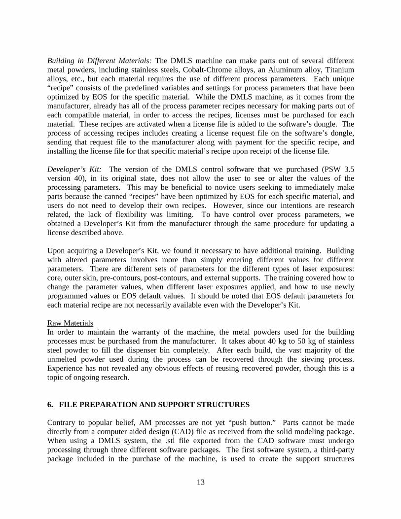
7. DMLS DESIGN GUIDELINES This section is not intended to be a “design for AM” tutorial or best practices. Rather, it is a compilation of considerations for designing, positioning, and orienting parts and support structures when using DMLS. While some aspects of these guidelines may apply to other AM processes, most of the considerations are unique to DMLS or, at least, to powder bed fusion processes. As with other AM processes, DMLS creates the part in a layer-upon-layer fashion. However, the method of creating each layer, i.e., the path of the laser beam used to melt metal within the powder bed, is particular to this machine and control software. The vast majority of the layers can be broken into two portions: the edges of the part and the core of the part. The DMLS system has different laser exposures for these two portions. The laser scans the edges of the part once before and once after scanning the core. The edges are exposed using a single contour of a focused laser beam at approximately 50 % of maximum power (200 W is maximum power). The core is exposed using a defocused laser beam near 100 % of maximum power that quickly rasters over a specified length. As the powder in the core of the part melts and re-solidifies, the level drops slightly. An analogy for this is a glass of ice cubes that melt and re-solidify (see Figure 8). The ice cubes (or metal powder) do not occupy 100 % of the volume below their upper level. However, when they melt, the liquid fills in the gaps that were present and the upper level drops. When the liquid re-solidifies, it is 100 % (or very nearly) dense and that top level remains the same as when the material was liquid. The level at the edges of the part, on the other hand, are slightly raised when compared to the core and to the original level of the powder (see Figure 9). The cause of this is under investigation.
Figure 8: Schematic illustrating the change in level upon melting and re-solidification
The different levels of the core and the edges lead to two of the four design guidelines discussed below. Contact Between Part and Recoating Blade When the recoating blade deposits a new layer of powder over the previous layer, there is generally contact between the recoating blade and the top of the sintered area of the previous layer. This contact results from the edges of the part being at a slightly raised level compared to the rest of the part. To keep the contact from becoming too extreme, we follow several guidelines for the positioning and orientation of the part(s) in the build volume.
upper level
Ice cubes (powder particles)
Melted and re-solidified material
19
Figure 9: Optical micrograph of a 1 mm diameter pin
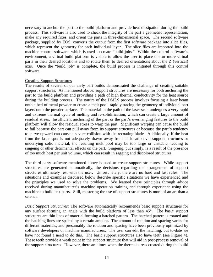
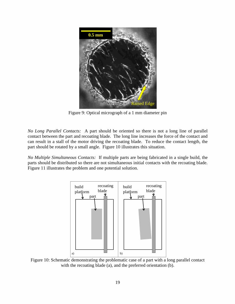
No Long Parallel Contacts: A part should be oriented so there is not a long line of parallel contact between the part and recoating blade. The long line increases the force of the contact and can result in a stall of the motor driving the recoating blade. To reduce the contact length, the part should be rotated by a small angle. Figure 10 illustrates this situation. No Multiple Simultaneous Contacts: If multiple parts are being fabricated in a single build, the parts should be distributed so there are not simultaneous initial contacts with the recoating blade. Figure 11 illustrates the problem and one potential solution.
Figure 10: Schematic demonstrating the problematic case of a part with a long parallel contact
with the recoating blade (a), and the preferred orientation (b).
recoating blade
build platform
part
recoating blade
build platform
part
a) b)
0.5 mm
Raised Edge
20
Figure 11: Schematic demonstrating the problematic case of multiple parts simultaneously
impacting the recoating blade (a), and the preferred orientation (b).
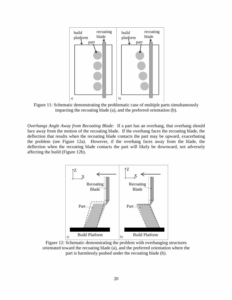
Overhangs Angle Away from Recoating Blade: If a part has an overhang, that overhang should face away from the motion of the recoating blade. If the overhang faces the recoating blade, the deflection that results when the recoating blade contacts the part may be upward, exacerbating the problem (see Figure 12a). However, if the overhang faces away from the blade, the deflection when the recoating blade contacts the part will likely be downward, not adversely affecting the build (Figure 12b).
Figure 12: Schematic demonstrating the problem with overhanging structures
orientated toward the recoating blade (a), and the preferred orientation where the part is harmlessly pushed under the recoating blade (b).
recoating blade
build platform
part
recoating blade
build platform
part
a) b)
ZX
Build Platform
Recoating Blade
Part
Recoating Blade
ZX
Build Platform
Part
a) b)
21
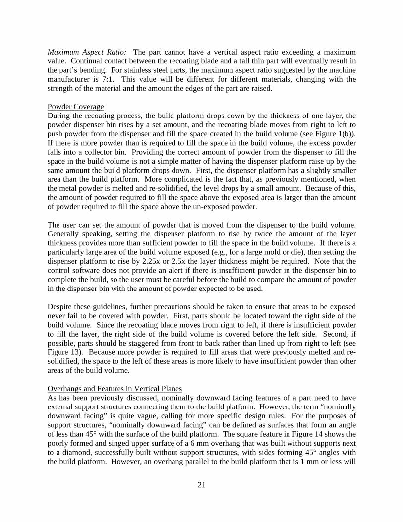
Maximum Aspect Ratio: The part cannot have a vertical aspect ratio exceeding a maximum value. Continual contact between the recoating blade and a tall thin part will eventually result in the part’s bending. For stainless steel parts, the maximum aspect ratio suggested by the machine manufacturer is 7:1. This value will be different for different materials, changing with the strength of the material and the amount the edges of the part are raised. Powder Coverage During the recoating process, the build platform drops down by the thickness of one layer, the powder dispenser bin rises by a set amount, and the recoating blade moves from right to left to push powder from the dispenser and fill the space created in the build volume (see Figure 1(b)). If there is more powder than is required to fill the space in the build volume, the excess powder falls into a collector bin. Providing the correct amount of powder from the dispenser to fill the space in the build volume is not a simple matter of having the dispenser platform raise up by the same amount the build platform drops down. First, the dispenser platform has a slightly smaller area than the build platform. More complicated is the fact that, as previously mentioned, when the metal powder is melted and re-solidified, the level drops by a small amount. Because of this, the amount of powder required to fill the space above the exposed area is larger than the amount of powder required to fill the space above the un-exposed powder. The user can set the amount of powder that is moved from the dispenser to the build volume. Generally speaking, setting the dispenser platform to rise by twice the amount of the layer thickness provides more than sufficient powder to fill the space in the build volume. If there is a particularly large area of the build volume exposed (e.g., for a large mold or die), then setting the dispenser platform to rise by 2.25x or 2.5x the layer thickness might be required. Note that the control software does not provide an alert if there is insufficient powder in the dispenser bin to complete the build, so the user must be careful before the build to compare the amount of powder in the dispenser bin with the amount of powder expected to be used. Despite these guidelines, further precautions should be taken to ensure that areas to be exposed never fail to be covered with powder. First, parts should be located toward the right side of the build volume. Since the recoating blade moves from right to left, if there is insufficient powder to fill the layer, the right side of the build volume is covered before the left side. Second, if possible, parts should be staggered from front to back rather than lined up from right to left (see Figure 13). Because more powder is required to fill areas that were previously melted and re-solidified, the space to the left of these areas is more likely to have insufficient powder than other areas of the build volume. Overhangs and Features in Vertical Planes As has been previously discussed, nominally downward facing features of a part need to have external support structures connecting them to the build platform. However, the term “nominally downward facing” is quite vague, calling for more specific design rules. For the purposes of support structures, “nominally downward facing” can be defined as surfaces that form an angle of less than 45° with the surface of the build platform. The square feature in Figure 14 shows the poorly formed and singed upper surface of a 6 mm overhang that was built without supports next to a diamond, successfully built without support structures, with sides forming 45° angles with the build platform. However, an overhang parallel to the build platform that is 1 mm or less will
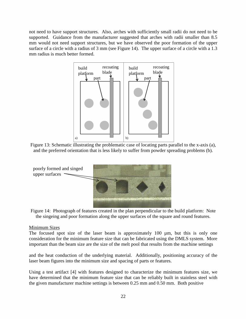
22
not need to have support structures. Also, arches with sufficiently small radii do not need to be supported. Guidance from the manufacturer suggested that arches with radii smaller than 8.5 mm would not need support structures, but we have observed the poor formation of the upper surface of a circle with a radius of 3 mm (see Figure 14). The upper surface of a circle with a 1.3 mm radius is much better formed.
Figure 13: Schematic illustrating the problematic case of locating parts parallel to the x-axis (a),
and the preferred orientation that is less likely to suffer from powder spreading problems (b).
Figure 14: Photograph of features created in the plan perpendicular to the build platform: Note
the singeing and poor formation along the upper surfaces of the square and round features. Minimum Sizes The focused spot size of the laser beam is approximately 100 µm, but this is only one consideration for the minimum feature size that can be fabricated using the DMLS system. More important than the beam size are the size of the melt pool that results from the machine settings and the heat conduction of the underlying material. Additionally, positioning accuracy of the laser beam figures into the minimum size and spacing of parts or features. Using a test artifact [4] with features designed to characterize the minimum features size, we have determined that the minimum feature size that can be reliably built in stainless steel with the given manufacturer machine settings is between 0.25 mm and 0.50 mm. Both positive
recoating blade
build platform
part
recoating blade
build platform
part
a) b)
poorly formed and singed upper surfaces

23
Figure 15: Optical micrographs of, from left to right, neighboring rectangular bosses,
neighboring rectangular holes, a round pin, and a round hole. The features in (a) are nominally 0.5 mm, and the features in (b) are nominally 0.25 mm.
(bosses or protrusions) and negative (holes) features of 0.50 mm are shown in Figure 15. The system attempted but generally failed to build features of 0.25 mm size. Photos of these failed features can be seen in Figure 15. These findings agree with the manufacturer quoted minimum feature size of 0.30 mm. One of the often-quoted benefits of AM is that it can produce fully functional parts having relative motion without the need for assembly. However, if the space between the parts to have relative motion is too small, they may fuse together because of overlapping heat-affected zones or they may seize because of interlocking surface roughness. To avoid these situations a minimum spacing should be observed. For stainless steel parts, a general guideline for minimum spacing is 0.20 mm. This value may vary for other materials or for other machine settings based on the size of the melt pool, the size of the heat-affected zone, and the achievable surface roughness. 8. POST PROCESSING One of the most surprising aspects of DMLS to us was the amount of recommended post processing. Once a part has been finished and removed from the DMLS machine, at least three post-processing steps are recommended. First, the part may be heat treated to relieve internal stresses. Next, the part may be shot peened to clean up the surface and impart compressive stresses in the surface. Third, the part must be cut off the build platform and other remaining support structures must be removed. The choice of whether or not to heat treat and shot peen may depend on the material or ultimate function of the part. Furthermore, some parts, especially titanium alloys, may require hot isostatic pressing (HIP) for optimal performance. The focus of
failed to build
(a)
(b)
0.5 mm

24
our research has been on characterizing the DMLS processes, so our experience with post processing is limited. Heat Treat Depending on the material and intended application, it may be necessary to perform thermal post-processing (i.e., heat treat) of the resulting AM parts to get the desired mechanical properties, such as for hardening or stress relief. For DMLS, it is recommended to heat treat parts made from stainless steel, cobalt-chrome materials, and other materials using a programmable, controlled-atmosphere oven. For example, stainless steel DMLS parts are recommended to be heat-treated for 1 h to 2 h at 650 °C to remove internal stresses and to maintain accurate part geometry. Additionally, inert atmosphere is recommended for the heat treatment process to avoid oxidation. Of the materials currently available from EOS, Cobalt Chrome MP1 requires the highest temperature of 1150 °C. Fabricated parts can be heat-treated while still fixed to the build platforms. All loose powder must be completely removed before beginning the heat treat process. To produce aerospace grade parts, the heat treatment must conform to certain standards and the treatment may need to be conducted in vacuum. The need for vacuum is significant because a furnace capable of pulling a vacuum is usually significantly more expensive than a furnace that merely floods the chamber with inert gas. However, if a furnace is not vacuum capable, it is impossible to eliminate all oxygen from the chamber, meaning there is always some risk of slight oxidation. Controlled atmospheres can be maintained within an existing oven through use of an internal vessel to contain the desired gas (with the part to be heat-treated within the vessel). Standards relevant to heat treatment are: MIL-STD 45662, AMS 2750, NADCAP CQ1-9, and ASTM E230. Shot Peening EOS provides two stand-alone shot peening stations with different sized metal spherical balls for post-processing of AM parts. Shot peening improves the part surface finish, changes the part color to be slightly lighter, and induces compressive surface stresses. The peening stations require a dedicated air line with pressurized air. The shot peeners also take up quite a bit of room, requiring a minimum floor area of 1.3 m x 1.3 m each. We recommended that ear protection (standard earplugs are sufficient) be used while shot peening due to the air flow noise generated during use. We also recommend that care be taken while shot peening such that the chamber gloves are not hit by the shot; this results in premature wear on the gloves. There is a balance between a part’s appearance and performance, and as such, careful consideration should be given when deciding whether to shot peen a given part. Some non-critical parts should be shot-peened when appearance is a major consideration. Other high-value parts (such as test artifacts) might not necessarily be shot-peened, since they are used in the metrology of the machine and its process, and as such, the shot peening will change the part’s dimension. We have seen that 4 mm diameter round stainless steel pins shrink in size by approximately 0.08 mm when shot peened, and 4 mm round holes grow in size by approximately 0.08 mm when shot peened.
25
Removal of Parts and Support Structures Because the parts come out of the machine fused to the build platform, post-processing to remove the parts is necessary. The two primary methods of removal are by wire-electro-discharge machining (wire-EDM) and by band saw. Each method has pros and cons and influences decisions on the geometry of support structures. Wire-EDM: Wire-EDM is the safer method and offers more flexibility in support structure strategy, but requires a more skilled operator and larger initial capital investment. When performing wire-EDM, the workpiece is often fully submerged in de-ionized water, or the work zone is at least flooded with dielectric fluid. Any powder trapped in the support structures will be safely flushed away into the dielectric fluid. Many EDM systems use 0.254 mm diameter wire, though larger and smaller wire thicknesses are available. As such, the height of the support structures anchoring the parts to the build platform can be rather short, approximately 0.5 mm or 1 mm. Further, wire-EDM is a non-contact thermal process, so it does not necessarily become more difficult if the material being cut is stronger. Due to the low applied forces from EDM, the part design is not hindered by support structures without teeth, support strategies with solid tabs, or strategies with no supports and the part directly fused to the build platform. A wire-EDM system is a computer numerically controlled (CNC) machine, so it is more precise and controlled than a manual machine. The removal process can be set up and programmed to remove the part at the interface between the supports and the part, which avoids further post processing to remove the remnants of the support structures from the part. However, this machine requires an operator capable of programming and setting up a CNC machine. Due to the need for a skilled operator and the large capital investment required for wire-EDM, machine shops may not have multiple wire-EDM systems. If this is the case, the wire-EDM removal of parts from the build platforms may become a bottleneck in the overall AM part fabrication process flow (depending on production volumes and system utilizations). Band Saw: A band saw is easier to use than a wire-EDM, but several factors must be considered if part removal is done with a band saw. Most importantly, operator safety is a concern when using a band saw with AM-fabricated parts, especially when dealing with parts made from highly reactive metal powders. Care should be taken to ensure that the heat in the cutting process does not get too high and cause the trapped powder in the part to ignite. Cutting fluid should always be used to reduce the heat and to flush away any powder trapped in the support structures. It is preferred to use an automated feed to minimize human interaction with the process, and the feedrate should be relatively low. If a manual feed is required, the operator should apply minimal pressure to feed the part. Operators may want to consider dedicating one or several band saws solely for cutting off DMLS parts from build platforms because the saws are likely to become contaminated with the powdered metal that is trapped in the support structures. Further, these systems may need more frequent cleaning or maintenance to ensure proper operation. The support structures must be taller when removing the part with a band saw because the kerf of the saw blade is usually much thicker than the diameter of the wire used in a wire-EDM system. A height of 5 mm is usually sufficient. Removal of parts built with the typical hatched support structures is usually rather straight forward, but removal of parts directly fused to the build platform may be significantly more difficult.
26
Hand Removal of Support Structures: Unless a part has a simple geometry with a flat base, some of the support structures will need to be removed by hand. Care must be taken when doing this in case there is any remnant powder trapped inside the support structures. To aid in the removal of these support structures, teeth should be included at the top of the support structures at the interface with the part (see Figure 4), if possible. These teeth offer a weak point in the connection that aids removal. The EOS informal recommendation for removal of these support structures is to crush them in a benchtop vice and use vice grips, a chisel, and other hand tools to pry and cut the parts off at the teeth. Our experience with removing support structures is that it is more art than science. Often times crushing the supports in a vice does an excellent job and the supports simply “pop” off at the teeth. Other times, crushing the supports in the vice only makes them more difficult to remove. In these cases, we use a combination of tools, including channel locks, handheld rotary devices, and grinding wheels. Regardless of the ease of manual removal, the part surfaces that required manual removal always show residual effects of the support structures, requiring further post-processing (sanding, grinding, or polishing) to remove. Further Considerations: It may be advantageous to configure build platforms or sub-plates with removal in mind. For example, adding machined holes near the edges of the build platform that conform to the work holding setup of the machine used to separate the parts from the build platform will significantly reduce the setup time for removal. Also, smaller sub-plates may be used for small parts. These small plates will be easier to fixture and will require less exposed wire or blade when cutting, reducing the likelihood for breakage as well as the amount of bending, resulting in a more precise cut. However, smaller sub-plates may make the DMLS setup more difficult because there is less surface area for leveling of the build platform and the areas surrounding the sub-plate need to be filled with metal powder. The method of removal may also impact the placement and orientation of multiple parts in the build process. Multiple parts should not be aligned with the EDM wire or saw blade. If the wire or blade needs to pass through multiple parallel parts, the dielectric or cutting fluid may be blocked by the upper or lower parts, resulting in poor cutting conditions for the inner parts. Build Platform Preparation: After removing the parts, the build platform must be re-surfaced to remove remnants of the support structures. The specifications for the build platform’s required surface finish are not always clear. Surface finish requirements differ based on the material of the build platform, i.e., surface finish specifications for steel are different from the specifications for aluminum or titanium build platforms. For steel build platforms, the manufacturer’s specifications for surface finish range from an Rz value of 10 µm to an Rz value of up to 60 µm. Build platforms can be re-surfaced by grinding or by milling. Build platforms for most AM metal powders are made from American Iron and Steel Institute (AISI) 1045 steel. This type of steel is easily ground, but can be milled without too much difficulty as well. A typical surface grinding process should easily achieve a surface roughness better than Rz = 10 µm. A milling process should be able to achieve a surface roughness better than Rz = 45 µm, but achieving a surface roughness of Rz = 10 µm may require careful selection of cutting parameters. For the
27
DMLS process, feedback from EOS is that the surface roughness of the build platform is not highly critical to the successful build of a part. If the resurfacing is done by grinding, it is specified by the manufacturer that the build platforms be demagnetized before re-use. This is because a magnetized build platform will adversely affect the recoating quality of a magnetic powder such as tool steel. Because of welding incompatibility with steel, build platforms for Aluminum parts are made from Aluminum and build platforms for Titanium parts are made from Titanium. Aluminum and Titanium are typically problematic for grinding processes, so these build platforms should be resurfaced by milling. 9. COST FACTORS The overall costs associated with implementing a metal AM system include the facility preparation costs, the system purchase price and installation costs, purchase prices and installation costs for supporting systems (e.g., a furnace for heat treatment, a wire-EDM for cutoff), and ongoing operating costs associated with consumables and post-processing. Typical consumables include the metal powders, system filters, gas cylinders, and chemicals for cleaning. Post-processing costs include the time and expense to remove the resulting parts from the build platform, to remove any expendable support structures, to heat-treat and/or shot peen the resulting parts, and to prepare the build platforms for the next build cycle. 10. CONCLUSIONS This publication has presented a summary of lessons learned by NIST during establishment of the NIST Metal Additive Manufacturing Laboratory and implementation of the metal additive manufacturing capability at NIST. These lessons learned have addressed room requirements, safety concerns, machine operation, materials and process parameters, file preparation and support structures, design guidelines, and post-processing of resulting parts. These lessons learned resulted from the first implementation of a metal additive manufacturing system at NIST. While the NIST experiences were with a particular metal AM system, we believe that these lessons are relevant and have common aspects for implementing other types of metal additive manufacturing systems. The intention is that this summary document will help others to implement metal additive manufacturing capabilities in their facilities. 11. REFERENCES [1] ASTM Standard F2792, 2012a, “Standard Terminology for Additive Manufacturing Technologies,” ASTM International, West Conshohocken, PA, 2012, DOI: 10.1520/F2792-12A. [2] Aluminum (Metallic, Powder); MSDS ACC#01000; Fisher Scientific: Fair Lawn, NJ, June 6, 2006. http://avogadro.chem.iastate.edu/MSDS/Al_powder.htm (accessed March 8, 2006).

28
[3] ASTM Standard F2921, 2011, “Standard Terminology for Additive Manufacturing—Coordinate Systems and Test Methodologies,” ASTM International, West Conshohocken, PA, 2012, DOI: 10.1520/F2921-11. [4] S. Moylan, J. Slotwinski, A. Cooke, K. Jurrens, and M.A. Donmez, 2012, “Proposal for a Standardized Test Artifact for Additive Manufacturing,” Proceedings of the Twenty Third Annual International Solid Freeform Fabrication Symposium, August 6-8, 2012, Austin, TX, USA, pp 903- 920.
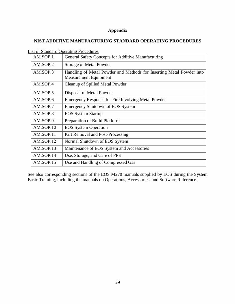
29
Appendix
NIST ADDITIVE MANUFACTURING STANDARD OPERATING PROCEDURES List of Standard Operating Procedures
AM.SOP.1 General Safety Concepts for Additive Manufacturing AM.SOP.2 Storage of Metal Powder AM.SOP.3 Handling of Metal Powder and Methods for Inserting Metal Powder into
Measurement Equipment AM.SOP.4 Cleanup of Spilled Metal Powder
AM.SOP.5 Disposal of Metal Powder AM.SOP.6 Emergency Response for Fire Involving Metal Powder AM.SOP.7 Emergency Shutdown of EOS System AM.SOP.8 EOS System Startup AM.SOP.9 Preparation of Build Platform AM.SOP.10 EOS System Operation AM.SOP.11 Part Removal and Post-Processing AM.SOP.12 Normal Shutdown of EOS System AM.SOP.13 Maintenance of EOS System and Accessories AM.SOP.14 Use, Storage, and Care of PPE AM.SOP.15 Use and Handling of Compressed Gas
See also corresponding sections of the EOS M270 manuals supplied by EOS during the System Basic Training, including the manuals on Operations, Accessories, and Software Reference.
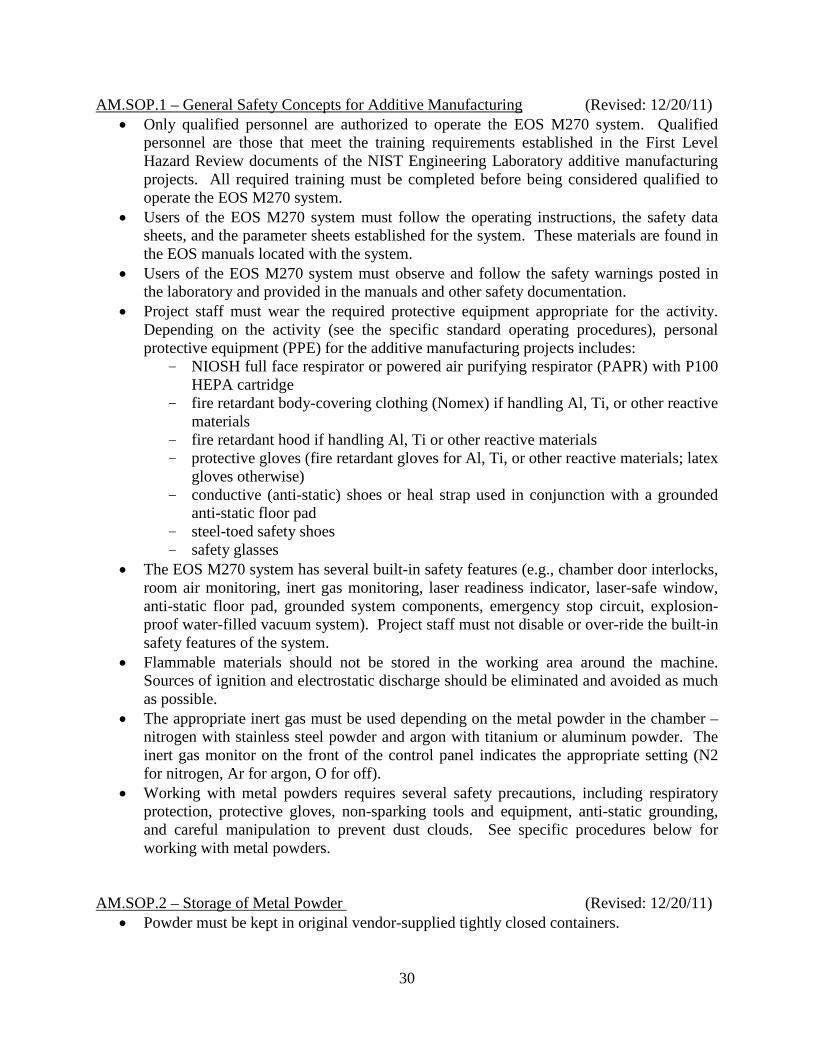
30
AM.SOP.1 – General Safety Concepts for Additive Manufacturing (Revised: 12/20/11) • Only qualified personnel are authorized to operate the EOS M270 system. Qualified
personnel are those that meet the training requirements established in the First Level Hazard Review documents of the NIST Engineering Laboratory additive manufacturing projects. All required training must be completed before being considered qualified to operate the EOS M270 system.
• Users of the EOS M270 system must follow the operating instructions, the safety data sheets, and the parameter sheets established for the system. These materials are found in the EOS manuals located with the system.
• Users of the EOS M270 system must observe and follow the safety warnings posted in the laboratory and provided in the manuals and other safety documentation.
• Project staff must wear the required protective equipment appropriate for the activity. Depending on the activity (see the specific standard operating procedures), personal protective equipment (PPE) for the additive manufacturing projects includes:
- NIOSH full face respirator or powered air purifying respirator (PAPR) with P100 HEPA cartridge
- fire retardant body-covering clothing (Nomex) if handling Al, Ti, or other reactive materials
- fire retardant hood if handling Al, Ti or other reactive materials - protective gloves (fire retardant gloves for Al, Ti, or other reactive materials; latex
gloves otherwise) - conductive (anti-static) shoes or heal strap used in conjunction with a grounded
anti-static floor pad - steel-toed safety shoes - safety glasses
• The EOS M270 system has several built-in safety features (e.g., chamber door interlocks, room air monitoring, inert gas monitoring, laser readiness indicator, laser-safe window, anti-static floor pad, grounded system components, emergency stop circuit, explosion-proof water-filled vacuum system). Project staff must not disable or over-ride the built-in safety features of the system.
• Flammable materials should not be stored in the working area around the machine. Sources of ignition and electrostatic discharge should be eliminated and avoided as much as possible.
• The appropriate inert gas must be used depending on the metal powder in the chamber – nitrogen with stainless steel powder and argon with titanium or aluminum powder. The inert gas monitor on the front of the control panel indicates the appropriate setting (N2 for nitrogen, Ar for argon, O for off).
• Working with metal powders requires several safety precautions, including respiratory protection, protective gloves, non-sparking tools and equipment, anti-static grounding, and careful manipulation to prevent dust clouds. See specific procedures below for working with metal powders.
AM.SOP.2 – Storage of Metal Powder (Revised: 12/20/11)
• Powder must be kept in original vendor-supplied tightly closed containers.
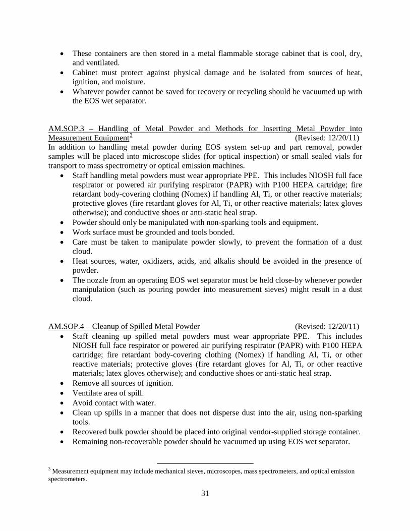
31
• These containers are then stored in a metal flammable storage cabinet that is cool, dry, and ventilated.
• Cabinet must protect against physical damage and be isolated from sources of heat, ignition, and moisture.
• Whatever powder cannot be saved for recovery or recycling should be vacuumed up with the EOS wet separator.
AM.SOP.3 – Handling of Metal Powder and Methods for Inserting Metal Powder into Measurement Equipment3 (Revised: 12/20/11) In addition to handling metal powder during EOS system set-up and part removal, powder samples will be placed into microscope slides (for optical inspection) or small sealed vials for transport to mass spectrometry or optical emission machines.
• Staff handling metal powders must wear appropriate PPE. This includes NIOSH full face respirator or powered air purifying respirator (PAPR) with P100 HEPA cartridge; fire retardant body-covering clothing (Nomex) if handling Al, Ti, or other reactive materials; protective gloves (fire retardant gloves for Al, Ti, or other reactive materials; latex gloves otherwise); and conductive shoes or anti-static heal strap.
• Powder should only be manipulated with non-sparking tools and equipment. • Work surface must be grounded and tools bonded. • Care must be taken to manipulate powder slowly, to prevent the formation of a dust
cloud. • Heat sources, water, oxidizers, acids, and alkalis should be avoided in the presence of
powder. • The nozzle from an operating EOS wet separator must be held close-by whenever powder
manipulation (such as pouring powder into measurement sieves) might result in a dust cloud.
AM.SOP.4 – Cleanup of Spilled Metal Powder (Revised: 12/20/11)
• Staff cleaning up spilled metal powders must wear appropriate PPE. This includes NIOSH full face respirator or powered air purifying respirator (PAPR) with P100 HEPA cartridge; fire retardant body-covering clothing (Nomex) if handling Al, Ti, or other reactive materials; protective gloves (fire retardant gloves for Al, Ti, or other reactive materials; latex gloves otherwise); and conductive shoes or anti-static heal strap.
• Remove all sources of ignition. • Ventilate area of spill. • Avoid contact with water. • Clean up spills in a manner that does not disperse dust into the air, using non-sparking
tools. • Recovered bulk powder should be placed into original vendor-supplied storage container. • Remaining non-recoverable powder should be vacuumed up using EOS wet separator.
3 Measurement equipment may include mechanical sieves, microscopes, mass spectrometers, and optical emission spectrometers.
32
AM.SOP.5 – Disposal of Metal Powder (Revised: 12/20/11) • Any powder remnants that cannot be reclaimed for reuse should be vacuumed up with the
EOS wet separator. • When full, the EOS wet separator should be emptied according to the maintenance
instructions in the EOS accessories manual. • Per guidance from the NIST Office of Safety, Health, and Environment (OSHE), the
resulting metal powder sludge from the cleaned EOS wet separator should be stored in a sealed plastic bag inside a metal container with a closed lid until picked up for disposal by NIST janitorial staff.
AM.SOP.6 – Emergency Response for Fire Involving Metal Powder (Revised: 12/20/11)
• In case of fire or ignition of metal powder, first get yourself and all nearby personnel out of the danger area. Then activate the nearest fire alarm (located in the hallway of NIST Building 304) and contact NIST Emergency Services by calling x2222 from a phone outside the danger area. Leave the building using the nearest safe exit and gather at the designated meeting point.
• For extinguisher-trained personnel only: - Activate the nearest fire alarm (located in the hallway of NIST Building 304) or
call x2222 before using the extinguisher. - If the fire is small, use ONE Class D extinguisher in an attempt to put the fire out. - Use only ONE extinguisher, and then leave the building using the nearest safe
exit. • Important Safety Note: Use only Class D fire extinguishers for fires involving metal
powder. Do not use water due to the reactivity of the metal powder with water. AM.SOP.7 – Emergency Shutdown of EOS System (Revised: 12/20/11)
• In case of emergency, press the red Emergency Stop button on the front of the system control panel to stop the EOS M270 system immediately.
• Emergency situations that would require an emergency shutdown of the EOS system may include NIST Building 304 water leaks that impact Room 118, Building 304 fire evacuations, weather emergencies that require evacuation or shelter-in-place, or failure of one or more system safety controls.
• Occupants must follow the instructions in the NIST Occupant Emergency Plan. AM.SOP.8 – EOS System Startup (Revised: 12/20/11)
• Before system startup, confirm that the power transformer is in the “On” position. Turn on the machine using the main switch and the control voltage button.
• Once the chiller starts and the computer boots, log in to the control computer and start the PSW control program. Before proceeding further, conduct the oxygen sensor test by holding the blue O2 Sensor Test button until the computer screen indicates “Successful.”
• The system pistons for the (1) recoating blade, (2) build platform, (3) collector platform, and (4) dispenser platform must be “homed” each time the system is started (four separate pistons). This must be done with the chamber door in the closed position and the access release button lighting up red (Note: Green means “safe” and the system cannot move; Red means “active”).
33
• The build chamber must be cleaned prior to the start of each build to remove the fine metal condensate that is created during system operation. With the build chamber door open, clean the metal condensate from the build chamber walls, ceiling, and door gasket using a paper shop towel wetted with an all-purpose cleaner. Since the metal condensate is flammable if given an ignition source, anti-static safety shoes or an anti-static heal-strap used in conjunction with a grounded anti-static floor pad must be worn when cleaning the metal condensate from steel or other non-reactive metals. When cleaning the metal condensate from aluminum, titanium, or other reactive metals, a NIOSH full face respirator or powered air purifying respirator (PAPR) with P100 HEPA cartridge and body-covering flame-retardant clothing (Nomex), gloves, and hood must be worn in addition to the anti-static PPE.
• The lens cover of the laser also must be cleaned prior to the start of each build. With the build chamber door open, clean the lens cover with the lens cleaning cloths wetted with high purity (99.99%) alcohol. Use a flashlight to ensure that no streaks remain.
• Per guidance from the NIST Office of Safety, Health, and Environment (OSHE), the soiled paper towels from cleaning the metal condensate from the build chamber and the lens cloths from cleaning the lens cover should be placed in a sealed plastic bag inside a metal container with a closed lid until picked up for disposal by NIST janitorial staff.
AM.SOP.9 – Preparation of Build Platform (Revised: 12/20/11)
• Prior to inserting the build platform into the chamber, raise the build platform to the top position and vacuum any remaining metal powder from the bolt holes.
• Prior to inserting the build platform into the chamber, clean off excess machine oils from the build platform using paper shop towels wetted with an all-purpose cleaner.
• Steel-toed safety shoes are necessary when lifting or moving heavy build platforms. In addition, the lifting trolley supplied by EOS is available for use when large parts are fabricated on the build platform.
• When mounting the build platform, first insert the bolts loosely (do not tighten). Turn on the build platform heating using the PSW control program. Tighten the bolts only after the build platform temperature reaches 80 ºC.
• Prior to the start of each build, the build platform must be leveled and positioned to have the appropriate relation with the recoating blade. Level the build platform according to the instructions provided in the EOS operations manual, first leveling the Y-axis with a feeler gauge (back to front), then leveling the X-axis with a dial indicator (left to right). Position the height of the build platform with respect to the recoating blade according to the instructions in the EOS operations manual based on the thickness of the feeler gauge and the layer thickness of the material used (.02 mm for stainless steel). Note that all system operations with the PSW control program are done using mm units.
• Prior to the start of each build, the supply of metal powder must be filled, leveled, and compacted. Staff handling metal powders must wear appropriate PPE. This includes NIOSH full face respirator or powered air purifying respirator (PAPR) with P100 HEPA cartridge; fire retardant body-covering clothing (Nomex) if handling Al, Ti, or other reactive materials; protective gloves (fire retardant gloves for Al, Ti, or other reactive materials; latex gloves otherwise); and conductive shoes or anti-static heal strap.
• Additional metal powder should be added (as needed for the specific build) by first lowering the powder dispenser platform, and then slowly pouring the metal powder from

34
the vendor-supplied container into the dispenser platform while holding the nozzle of the operating EOS wet separator close-by. Care should be taken to minimize the potential for a dust cloud. Dust can be reduced by lowering the dispenser platform a small amount at a time and filling the powder dispenser in increments. The desiccant pack should be removed from the stored metal powder prior to filling the dispenser. The vendor-supplied containers are custom-sized to fit within the system build chamber during filling of the dispenser platform. After adding the metal powder to the dispenser platform, vacuum any extraneous powder from the outside of the container, replace the desiccant pack in the container, and reseal the container for later use.
• Prior to each build, the metal powder in the dispenser platform must be leveled by hand using a non-sparking tool. In addition, the metal powder must be compacted by pressing down on the powder with the non-sparking tool. Finally the powder dispenser platform should be raised and the final leveling of the powder done using the system recoating blade.
• Once the build platform and metal powder supply are prepared (and the build chamber and lens cover are cleaned), the chamber door should be closed and the inert gas flow started using the PSW control program to pre-flood the chamber. Confirm that the gas flow meters indicate that the inert gas flow has begun.
AM.SOP.10 – EOS System Operation (Revised: 12/20/11)
• The EOS is designed to operate for long periods unattended. Typical build times range from several hours to several days, depending on the numbers of parts and the part sizes. A typical small build may be prepared during the day and run unattended overnight to fabricate the parts. If an error or other problem occurs during operation (such as a power outage or other interruption), sufficient built-in controls and safety features are incorporated to halt the system in a safe status.
• Care must be taken during the offline data preparation steps of a build to ensure that in-process fabricated parts do not come loose from the build platform. If this happens, the recoating blade will contact the “floating” part and crash (shut down) the build, possibly damaging the ceramic recoating blade.
• When fabricating large parts, extra care must be taken to ensure that sufficient support structures are incorporated to fix the in-process part to the build platform.
AM.SOP.11 – Part Removal and Post Processing (Revised: 12/20/11)
• After completion of a build, parts must be removed according to the instructions in the EOS operations manual.
• When removing parts from the build chamber, staff must wear appropriate PPE. This includes NIOSH full face respirator or powered air purifying respirator (PAPR) with P100 HEPA cartridge; fire retardant body-covering clothing (Nomex) if handling Al, Ti, or other reactive materials; protective gloves (fire retardant gloves for Al, Ti, or other reactive materials; latex gloves otherwise); and conductive shoes or anti-static heal strap.
• Upon opening the build chamber door, allow the oxygen level to increase to 18% (indicated by the PSW control program) and conduct an oxygen sensor test by holding the blue O2 Sensor Test button until the computer screen indicates “Successful.” Excess powder on the build chamber door, door frame, and face of the machine should be vacuumed into the EOS wet separator.
35
• The metal powder should be carefully moved using non-sparking hand tools from the build platform and the collector platform back into the powder dispenser (moving powder left to right in the build chamber). The unused powder should be run through the sieve tray as it is moved back into the powder dispenser to remove extraneous bits of fused powder. Care should be taken to prevent a dust cloud from forming as the powder is moved. The nozzle of the operating EOS wet separator should be held close-by to collect any dust cloud.
• Steel-toed safety shoes are necessary when removing heavy build platforms. In addition, the lifting trolley supplied by EOS is available for use when large parts are fabricated on the build platform.
• The resulting parts should be heat-treated while still fixed to the build platform using a programmable oven according to the instructions in the EOS operations manual. Heat resistant gloves must be used when removing post-processed parts from the heat treat oven. Parts should be allowed to cool before removing from the oven if acceptable for the specified heat treatment.
• Following the heat treat, the fabricated parts must be removed from the build platform using either electrical discharge machining (EDM) or metal sawing operations, both available as a service from NIST Fabrication Services. If the parts are cut from the build platform while “dry” (typically not the case if EDM is used), machining operators must wear appropriate respiratory PPE (NIOSH full-face respirator or powered air purifying respirator (PAPR) with P100 HEPA cartridge) due to the potential for embedded metal powder remaining inside the part.
• Once released from the build platform, supporting material typically must be removed from the fabricated parts using a variety of hand finishing operations, typically involving bench vises and hand tools. Protective gloves should be worn as needed during these hand finishing operations.
• The final step to complete the fabricated parts is to shot peen the parts with steel or ceramic balls to compact the outer surfaces of the parts, add (desirable) compressive stresses, and improve the surface finish of the parts.
• The used build platforms must be machined flat for future reuse for new parts. Suitable grinding operations are available as a service from NIST Fabrication Services.
AM.SOP.12 – Normal Shutdown of EOS System (Revised: 12/20/11)
• After completion of a build, removal of the parts, and (preferred but optional prior to normal shutdown) cleaning of the build chamber to prepare for the next build, the system can be powered down by (1) ending the PSW control program, (2) shutting down the control computer, and (3) turning off the machine main switch. After shutting off the machine main switch, watch for the three lights in the (front left) cabinet to flash red indicating complete shutdown.
AM.SOP.13 – Maintenance of EOS System and Accessories (Revised: 12/20/11)
• The EOS system and its accessories must be maintained according to the instructions in the EOS operations and accessories manuals. In particular, specific guidance is provided for maintaining the chiller unit, the recirculation system, the wet separator, and the recoating blade.

36
• NIST staff should never attempt to modify, fix, or maintain the EOS laser system or to access the laser delivery path. Laser covers and laser safety controls are to remain intact for all NIST operations. All maintenance of the laser system is to be performed by a trained EOS service technician during service visits. A laser safety warning sign is to be placed at the entrance to the laboratory when the EOS service technician is working on the laser system.
• Appropriate PPE must be worn when replacing the ceramic re-coater blade, including protective gloves, respiratory protection, and anti-static safety shoes or anti-static heal-strap used in conjunction with a grounded anti-static floor pad. The sieve tray for the metal powder should be in place over the dispenser platform when replacing the re-coater blade to ensure that the small bolts holding the blade cover do not fall into the metal powder.
• Important Safety Note: Replacing the dirty filters to maintain the recirculation system is viewed as potentially the most hazardous operation necessary in using the EOS system. The recirculation system holds two large filters (top and bottom) that filter the inert gas flow and collect fine metal condensate from the build chamber. Each of the filters is grounded to the cabinet of the recirculation system to reduce the chance for static discharge. Due to the high flammability and quantity of metal condensate in these filters, full flame-retardant clothing, gloves, and hood and the anti-static PPE are mandatory when changing the filters of the recirculation system, regardless of the type of metal powders used. At least two NIST project staff must be present to perform the filter change, with full flame-retardant PPE worn by everyone and no exposed skin visible for anyone in the metal additive manufacturing laboratory. The filter change must be performed according to the instructions in the EOS accessories manual. Since the filters are bulky, the lifting trolley supplied by EOS should be used in removing the old filter and in installing the new filter. Once a filter is removed, the filter should be wetted with water to further prevent static discharge and the dampened filter must be placed in a large plastic bag for disposal – the filter cannot be reused or stored.
AM.SOP.14 – Use, Storage, and Care of PPE (Revised: 12/20/11)
• Each project member shall be issued a full-face respirator (based on the results of the fitting by the NIST Safety Office) and hood(s) for the powered air purifying respirator (PAPR) units for their individual use. The respirators and hoods will be labeled for identification purposes.
• The batteries for the powered air purifying respirator (PAPR) units shall remain plugged in to the chargers when not in use.
• Full-face respirators are to be cleaned with antiseptic wipes on a regular basis as instructed by the NIST Safety Office to remove any accumulations or potential respiratory hazards (e.g., metal powder). Cleaned respirators shall be stored in individual sealed (ziplock-type) plastic bags to keep them ready for the next use.
• Full-face respirators are to be tested (both inhaling and exhaling) prior to each use to ensure that the cartridges are not plugged. Replacement cartridges will be kept on-hand so that work is not delayed.
• The two anti-static heel straps provided with the EOS M270 system shall remain in the metal additive manufacturing laboratory.

37
• Fire retardant body-covering clothing and protective gloves (both fire-retardant and latex) in a variety of sizes shall be available in the metal additive manufacturing laboratory.
• The full-face respirators, PAPR hoods, fire retardant clothing, protective gloves, and anti-static heel straps are to be stored in the designated PPE cabinet(s) within the metal additive manufacturing laboratory. Specifically, these items are not to be removed from the laboratory so that any trace amounts of metal powder are contained and not spread to other areas unintentionally.
AM.SOP.15 – Use and Handling of Compressed Gas (Revised: 12/20/11)
• Project staff must be familiar with safe use and handling of compressed gas. General safety information on gas cylinder handling is provided on the NIST Safety web site and is covered by NIST Health and Safety Instruction (HSI) No. 5. Direct exposure to high-pressure gas from a nozzle can perforate your skin and can damage soft tissues of the body, such as your eyes. High flow rates cause noise that can produce hearing loss. Rapid release of gas can lead to oxygen depletion and suffocation.
• Safety glasses with side shields and protective footwear must be worn during all phases of gas cylinder operation, including storage, use, relocation, and disposal.
• The EOS system requires Argon gas cylinders only when building parts from aluminum and titanium powders. When building parts from stainless steel powder, the EOS system generates the Nitrogen inert atmosphere in the build chamber using a built-in function (i.e., Nitrogen gas cylinders are not necessary).
• The EOS system includes built-in oxygen sensors to monitor the system environment (both within the build chamber and in the machine cabinet), as well as a visible/audible warning system to warn of potential hazardous situations. As an extra precaution, an additional oxygen sensor and alarm system will be installed in the laboratory to monitor the oxygen concentration in the room.
• Gas cylinders should be securely fastened to a fixed holder at all times (during storage, usage, and disposal) to prevent them from falling over. Transport of gas cylinders only should be done using a stable, approved cylinder cart. Gas cylinders are Full, In Use, or Empty, and are tagged with a status coupon to indicate their status. Gas cylinders should be properly capped when not in service. Cylinders with status indicating Full or Empty should be capped by definition. Whenever the cap on the gas cylinder is removed, it is understood to be In Use and the coupon should reflect this status. Any cylinder that has not been used for more than 24 hours is considered to be in storage and must have the regulator removed and a proper cap secured. When the gas cylinder has been emptied, the cylinder status should be changed to indicate Empty and the cylinder should be taken out of service and disposed of according to NIST guidelines.
Experimental work for the NIST projects will use only powder materials that can be processed in a nitrogen environment for the projected future; no aluminum or titanium powder materials will be used (and so no Argon gas cylinders) until further safety controls are in place and the hazards are reassessed in the future.
Related Documents