Lesson Using Pneumatic Systems

Lesson
Dec 30, 2015
Lesson. Using Pneumatic Systems. Interest Approach. Can you explain how air makes a pneumatic hand tool work?. Student Learning Objectives. Define pneumatics and explain the major parts of a supply system. Describe the purpose of a flow meter. Explain the safety practices for pneumatics. - PowerPoint PPT Presentation
Welcome message from author
This document is posted to help you gain knowledge. Please leave a comment to let me know what you think about it! Share it to your friends and learn new things together.
Transcript

Lesson
Using Pneumatic Systems

Interest Approach
Can you explain how air makes a pneumatic hand tool work?

Student Learning Objectives
Define pneumatics and explain the major parts of a supply system.
Describe the purpose of a flow meter.
Explain the safety practices for pneumatics.

Terms
Air filterAir storage tankCompressorFlow meterManifoldMotorNeedle valves
Pressure limit switch
Pressure regulator
Pressure system gauge
Safety filterSafety valve
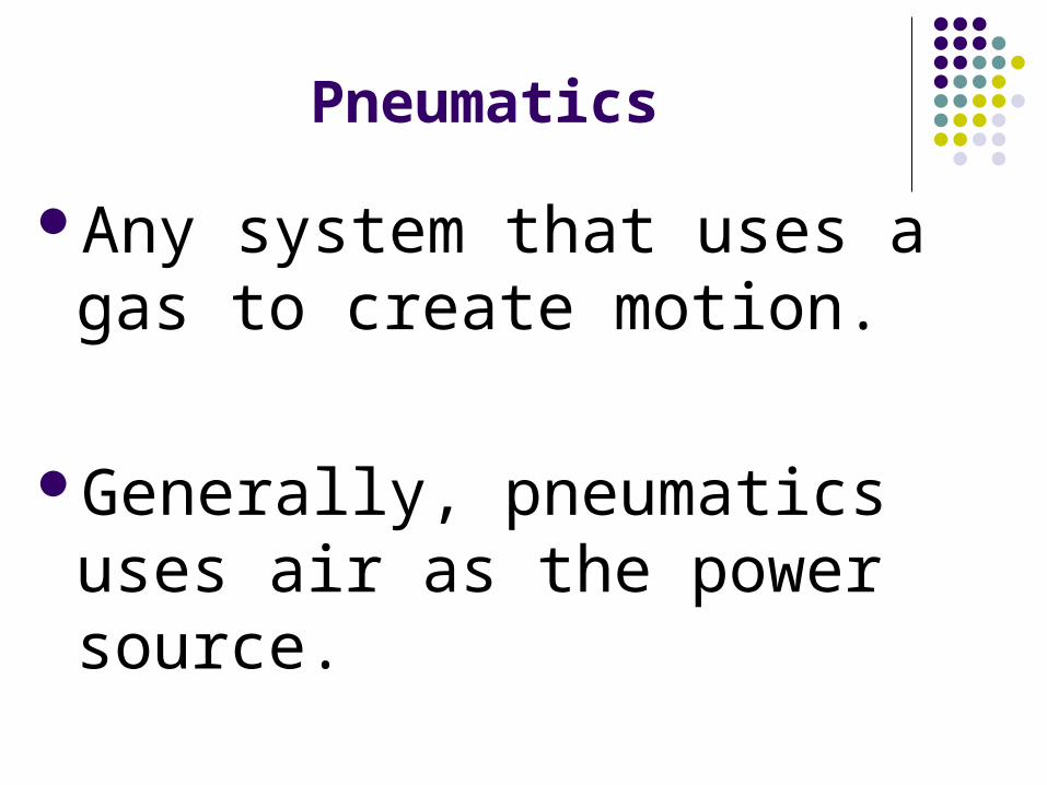
Pneumatics
Any system that uses a gas to create motion.
Generally, pneumatics uses air as the power source.


Parts of a Pneumatic Supply System
1) Motor
2) Compressor
3) Ail filter
4) Safety filter
5) Safety valve
6) Air storage tank
7) Pressure limit switch
8) Pressure regulator
9) Pressure system
10) Gauge
11) Manifold
12) Needle valves


Parts of a pneumatic system
Motor – converts electricity from the wall outlet into rotary motion.
Compressor – takes in air from the atmosphere and pushes the air into a storage tank.
Air filter – removes the dirt from the air.Safety filter – secondary device for
removal of dirt.


Parts (continued)
Safety valve – allows extra air to escape.
Air storage tank – holds a supply of pressurized air.
Pressure limit switch – detects the presence of the air in the storage tank.


Parts (continued)
Pressure regulator – controls the pressure of air.
Pressure system gauge – shows the pressure of the air.


Parts (continued)
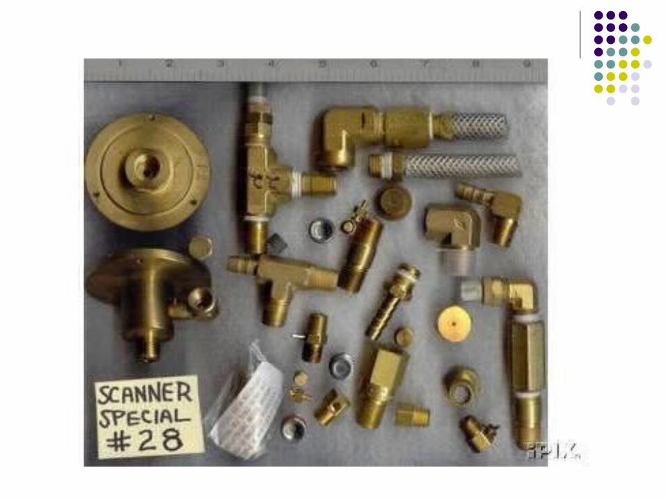
Manifold – has two connections between their air supply system and the pneumatic circuit.
Needle valves – stop the supply of pressurized air to the circuit.

Flow Meter
Measures the amount of air flowing through a pneumatic circuit.
Measured in standard cubic feet per hour (SCFH).

Pneumatic Safety Practices
Always wear safety glasses or goggles.
Keep all body parts and loose objects away from operating cylinders.
Always close the needle valve on the manifold before changing a pneumatic circuit.
Safety Practices (continued)
Always read the directions completely before working on any pneumatic system.
Handle all electrical components and fittings carefully.

Review / Summary
What is pneumatics and what are the major parts of the supply system?
What functions does the flow meter perform?
What safety practices are used in pneumatics?
Related Documents