Front cover Lenovo Networking Best Practices for CNOS: Layer 2 Design and Configuration Presents recommended design options for network topology Provides example configurations for specific features on Lenovo switches Illustrates recommended traffic flows based on network topology Includes troubleshooting recommendations for switching issues Scott Lorditch

Welcome message from author
This document is posted to help you gain knowledge. Please leave a comment to let me know what you think about it! Share it to your friends and learn new things together.
Transcript

Front cover
Lenovo Networking Best Practices for CNOS: Layer 2 Design and Configuration
Presents recommended design options for network topology
Provides example configurations for specific features on Lenovo switches
Illustrates recommended traffic flows based on network topology
Includes troubleshooting recommendations for switching issues
Scott Lorditch

2 Lenovo Networking Best Practices for CNOS: Layer 2 Design and Configuration
Abstract
This paper presents recommended topologies and configurations for the layer 2 portion of a network topology which includes Lenovo® switches with CNOS. It includes discussion of connectivity to upstream routed environments and downstream servers.
This document is intended for network architects and engineers who work for end-user organizations or for Lenovo and its business partners. The document will be most useful for those who have experience working on network design andr implementation and are familiar with Ethernet and its associated protocols.
At Lenovo Press, we bring together experts to produce technical publications around topics of importance to you, providing information and best practices for using Lenovo products and solutions to solve IT challenges.
See a list of our most recent publications at the Lenovo Press web site:
http://lenovopress.com
Contents
Introduction . . . . . . . . . . . . . . . . . . . . . . . . . . . . . . . . . . . . . . . . . . . . . . . . . . . . . . . . . . . . . . 3Virtual Link Aggregation Group considerations . . . . . . . . . . . . . . . . . . . . . . . . . . . . . . . . . . . 3Layer 2 failover. . . . . . . . . . . . . . . . . . . . . . . . . . . . . . . . . . . . . . . . . . . . . . . . . . . . . . . . . . . 25IGMP Snooping considerations . . . . . . . . . . . . . . . . . . . . . . . . . . . . . . . . . . . . . . . . . . . . . . 25Link aggregation. . . . . . . . . . . . . . . . . . . . . . . . . . . . . . . . . . . . . . . . . . . . . . . . . . . . . . . . . . 25Spanning Tree Protocol . . . . . . . . . . . . . . . . . . . . . . . . . . . . . . . . . . . . . . . . . . . . . . . . . . . . 28Storm Control considerations. . . . . . . . . . . . . . . . . . . . . . . . . . . . . . . . . . . . . . . . . . . . . . . . 33BootP and DHCP relay . . . . . . . . . . . . . . . . . . . . . . . . . . . . . . . . . . . . . . . . . . . . . . . . . . . . 34Change history . . . . . . . . . . . . . . . . . . . . . . . . . . . . . . . . . . . . . . . . . . . . . . . . . . . . . . . . . . . 37Author. . . . . . . . . . . . . . . . . . . . . . . . . . . . . . . . . . . . . . . . . . . . . . . . . . . . . . . . . . . . . . . . . . 37Notices . . . . . . . . . . . . . . . . . . . . . . . . . . . . . . . . . . . . . . . . . . . . . . . . . . . . . . . . . . . . . . . . . 38Trademarks . . . . . . . . . . . . . . . . . . . . . . . . . . . . . . . . . . . . . . . . . . . . . . . . . . . . . . . . . . . . . 39
Do you have the latest version? We update our papers from time to time, so check whether you have the latest version of this document by clicking the Check for Updates button on the front page of the PDF. Pressing this button will take you to a web page that will tell you if you are reading the latest version of the document and give you a link to the latest if needed. While you’re there, you can also sign up to get notified via email whenever we make an update.

Introduction
This paper describes the best practices for designing the topology for the Layer 2 portion of a network.
Layer 2 is the switching layer of a network. In this paper we cover networks built on Ethernet, where forwarding decisions are based upon Ethernet MAC addresses. Key aspects of Layer 2 include redundant and parallel links (aggregations), and dealing with topologies which include loops which can result in broadcast storms (spanning tree and related techniques).
The vast majority of the practices and techniques in this paper are readily applicable to networks which contain other vendors’ products in addition to those from Lenovo.
The paper is part of a series of papers that cover the design of Layer 1 (physical), Layer 2 (switching) and Layer 3 (routing) aspects of a network. The other two papers are available from these web pages:
� Layer 1 paper: Lenovo Networking Best Practices for CNOS: Network Design and Topologies, https://lenovopress.com/lp1068
� Layer 3 paper: Lenovo Networking Best Practices for CNOS: Layer 3 Technology, https://lenovopress.com/lp1087
Virtual Link Aggregation Group considerations
This section introduces virtual Link Aggregation Groups (vLAGs) and describes considerations for operating switches in a vLAG environment.
Introduction to vLAG
vLAG is a feature on Lenovo Networking switches that allows a pair of switches to act as a single endpoint for aggregation and is similar in function to Cisco Virtual PortChannel (vPC), Juniper MC-LAG, and others. There is no IEEE or IETF standard that defines this function. It provides improved high availability compared to a single switch that is acting as an endpoint and can enhance performance by splitting loads across the aggregated links and switches.
For more information about configuring the vLAG feature, see the Application Guide for your product.
Understanding packet flow in a vLAG environment
This section describes how traffic flows when vLAG is enabled; specifically, the potential for normal traffic to use the Inter-Switch Links (ISLs) between a pair of vLAGed switches in certain designs.
Related terms and conceptsThe following related terms and concepts are important for understanding packet flow in this environment:
� Link Aggregation (LAG) is also referred to as PortChannel, EtherChannel, trunking, and other terms. This section uses the terms Aggregation or LAG to refer to the bundling of physical links to act as a single logical link. Figure 1 on page 4 shows an example of
© Copyright Lenovo 2019. All rights reserved. 3

traditional LAG with a simple, four-port aggregation (the maximum number of ports that are supported in aggregation is vendor and device specific). Aggregations with a Lenovo switch use standards body (IEEE 802.3AX LACP) or industry standards (for static aggregation) to ensure compatibility between vendors.
Figure 1 Example of a simple Link Aggregation
� vLAG is similar to Cisco vPC or Juniper MC-LAG. Lenovo Networking vLAG is a form of multi-chassis (multi-switch) aggregation. vLAG is not a form of aggregation in its own right; instead, it is an enhancement to current aggregation standards. vLAG attempts to overcome a shortcoming of standards-based aggregations.
By current standards definitions, an aggregation can connect two devices only (see “Traditional LAG” in Figure 1). In traditional LAG, if one device on either end of the aggregation fails, the entire path is gone. By using vLAG, you can take a pair of switches and make them logically act as a single switch for aggregation purposes (see the split LAG example in Figure 2). This example splits the aggregation on the end that is running vLAG (or both sides if the other side is also running some form of split LAG); therefore, a single switch failure in that pair does not take down the entire path.
Figure 2 Example of cross switch aggregation with vLAG
� Local preference is used in multi-chassis aggregation environments (such as vLAG), where a single aggregation might have links to a single upstream path split over ports on two different switches. To understand the need for local preference in vLAG environments,
Device 2
Device 1
LAG (Aggregation)
LAG (Aggregation)
Traditional LAG
vLAG/vPC
vLAG/vPC
Device 2a
Device 1a
Device 2b
Device 1b
Split LAG (also known as vLAG, vPC, etc)
4 Lenovo Networking Best Practices for CNOS: Layer 2 Design and Configuration

it is helpful to first understand how packet flow works without local preference. Note that local preference is the default behavior of vLAG on CNOS software.
Without local preference, a packet on one switch in the vLAG pair that needed to get upstream uses normal aggregation hashing. It might use the other switch in the pair to get to the upstream network and add an unnecessary hop across the ISL before it heads upstream (the ISL connects the physical pair to help form the virtual pair). An example of this extra hop is shown in Figure 3.
Figure 3 Without local preference, packets might take the ISL, even if local links are up
With local preference, if a packet on a switch in the pair needs to get to the upstream network and if that switch has any links in that common cross chassis aggregation toward the destination that is up, the switch always prefers the local links to send to the upstream, and does not add that extra hop. An example of this operation is shown in Figure 4 on page 6.
In order to offer local preference, both vLAG peers should have the same MAC entries in their mac-address table every time and this is done using an FDB sync mechanism that works as follows:
– The MAC entries locally learned on one switch over vLAG port-channel are synchronized on its peer over the port-channel from the corresponding instance. In this case, FDB synchronization only works when the vLAG instance is formed.
– The MAC entries locally learned on one switch over non-vLAG port are synchronized on its peer over the ISL port-channel. In this case, FDB synchronization happens as long as there is one vLAG instance formed.
FDB synchronization is also necessary for MAC entries that are aged or purged. Also, when user manually clears the mac-address table on one of the vLAG switches, only the locally learned addresses are deleted, the ones learned by synchronization remain in FDB table (let’s say user clears mac-address-table on vLAG Primary switch – then all locally learned addresses on Primary are deleted but also the ones Secondary corresponding to the ones learned from Primary by synchronization; on both switches, they remain the mac entries locally learned by Secondary and hence by Primary by synchronization).
Switch-1 Switch-2
ESXi Server
vSwitch1ESX Route based on Originating virtual port ID
VM110.10.10.1
vmnic0 vmnic1
vLAGAggregation
Possible path WITHOUT local preference(Extra hop might go over ISL to get out)
ISL
5

When ISL comes up, each vLAG switch installs its peer MAC address as a static mac-address entry in FDB for ISL port-channel and each VLAN it is a member of, need to avoid unnecessary traffic flooding of traffic towards the peer switch.
On current implementation, vLAG feature can synchronize a maximum of 32K MAC entries.
vLAG does not take care of static mac address synchronization hence static addresses manually configured on one side should be configured accordingly on the other peer.
Figure 4 With local preference, local links take precedence over the hash
In addition to reducing hops, local preference also reduces the overall load on the ISL between the pair of vLAGed switches, which might permit having a smaller ISL than if the local preference is not used. Local preference is built into vLAG and cannot be disabled. All versions of vLAG support local preference, but not all vendors support it in their implementations of cross-chassis aggregation technologies.
� Switch independent mode teaming and switch dependent mode teaming (which is also known as bonding in some operating systems) is a method of combining NICs in the server to increase performance and high availability. Some of these teaming modes can affect how the upstream switches to the server must be configured and how traffic flows through a vLAGed environment. Switch independent mode teaming does not require configuration on the switch (except for allowing the specified VLANs). Switch-dependent mode teaming requires a form of special configuration on the switch (in the form of aggregation) to interoperate with the teaming mode on the server.
For more information about teaming modes and their interaction and operation, see An Introduction to NIC Teaming with Lenovo Networking Switches, which is available from:
https://lenovopress.com/redp5245
The remaining parts of this section describe the examples that are shown in Figure 5 on page 7 with switch-independent mode teaming, and Figure 6 on page 9 with switch-dependent mode teaming to help show how packets can flow in an environment that features vLAG.
Switch-1 Switch-2
ESXi Server
vSwitch1ESX Route based on Originating virtual port ID
VM110.10.10.1
vmnic0 vmnic1
vLAGAggregation
Possible path WITH local preference(Would only use ISL if all local uplinks were down)
ISL
6 Lenovo Networking Best Practices for CNOS: Layer 2 Design and Configuration

Packet flow with switch-independent mode teamingThe example that is shown in Figure 5 is described in this section, via step-by-step numbered packet flows.
Figure 5 Possible packet flows with a host that uses a non-aggregation form of teaming
This packet flow includes the following steps, as shown in Figure 5:
1. In this example, the vSwitch in the local host is not running an aggregation-based teaming; instead, it uses load balance per virtual machine (VM) (this setting is the default setting in an ESX vSwitch). The vSwitch for VM1 uses only one of the vmnics (that is, the network interface cards) for all conversations for VM1 into and out of the ESX host. For this example, assume that it hashed to using vmnic0 to the left side for VM1 (it might as well decide to use vmnic1, but whatever vmnic the vSwitch does hash VM1 to, it sends packets from VM1 only out that direction and accepts packets that are destined for VM1 only back on that same vmnic if vmnic stays up).
2. VM1 pings the remote host for the first time. Therefore, an Address Resolution Protocol (ARP) broadcast is sent to Access Switch #1. When you are using local preference, Switch #1 always sends that packet over one of its own uplinks (if a local uplink is available), not the ISL. For this example, assume that it chose to forward the packet toward Aggregation Switch #1 (although it might also send it to Aggregation Switch #2).
3. The packet gets to Aggregation Switch #1, which uses its own hash to send it to the remote host. If Aggregation Switch #1 has local preference enabled, it uses the port to
Agg Sw-1 Agg-Sw-2
Access Sw-1 Access Sw-2
Compute Node - ESX
vSwitch1ESX Route based on Originating virtual port ID
VM110.10.10.1
vmnic0 vmnic1
vLAGAggregation
vLAG or vPCAggregation
Remote host - Bond0 interface = 10.10.10.2
vLAG or vPCAggregation
ISL
VLAN XEnd to End
vPC Peer link or ISL
Eth0 Eth1Bond0 – Mode 4
Green represents possible north bound paths
(only one will be taken)
Red represents possible south
bound paths
(only one will be taken)
Teaming NOT using
aggregation
LAG (Aggregation)
1
2
3 4
5 6
7
8
9
7
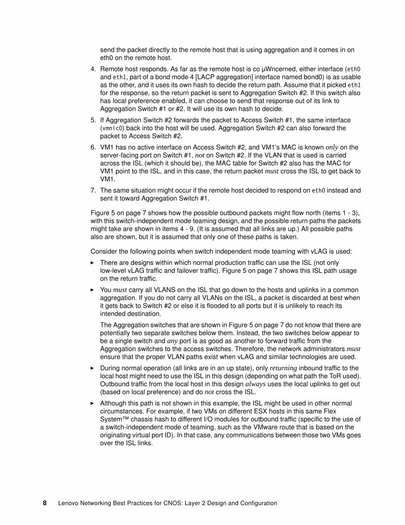
send the packet directly to the remote host that is using aggregation and it comes in on eth0 on the remote host.
4. Remote host responds. As far as the remote host is co μWncerned, either interface (eth0 and eth1, part of a bond mode 4 [LACP aggregation] interface named bond0) is as usable as the other, and it uses its own hash to decide the return path. Assume that it picked eth1 for the response, so the return packet is sent to Aggregation Switch #2. If this switch also has local preference enabled, it can choose to send that response out of its link to Aggregation Switch #1 or #2. It will use its own hash to decide.
5. If Aggregation Switch #2 forwards the packet to Access Switch #1, the same interface (vmnic0) back into the host will be used. Aggregation Switch #2 can also forward the packet to Access Switch #2.
6. VM1 has no active interface on Access Switch #2, and VM1’s MAC is known only on the server-facing port on Switch #1, not on Switch #2. If the VLAN that is used is carried across the ISL (which it should be), the MAC table for Switch #2 also has the MAC for VM1 point to the ISL, and in this case, the return packet must cross the ISL to get back to VM1.
7. The same situation might occur if the remote host decided to respond on eth0 instead and sent it toward Aggregation Switch #1.
Figure 5 on page 7 shows how the possible outbound packets might flow north (items 1 - 3), with this switch-independent mode teaming design, and the possible return paths the packets might take are shown in items 4 - 9. (It is assumed that all links are up.) All possible paths also are shown, but it is assumed that only one of these paths is taken.
Consider the following points when switch independent mode teaming with vLAG is used:
� There are designs within which normal production traffic can use the ISL (not only low-level vLAG traffic and failover traffic). Figure 5 on page 7 shows this ISL path usage on the return traffic.
� You must carry all VLANS on the ISL that go down to the hosts and uplinks in a common aggregation. If you do not carry all VLANs on the ISL, a packet is discarded at best when it gets back to Switch #2 or else it is flooded to all ports but it is unlikely to reach its intended destination.
The Aggregation switches that are shown in Figure 5 on page 7 do not know that there are potentially two separate switches below them. Instead, the two switches below appear to be a single switch and any port is as good as another to forward traffic from the Aggregation switches to the access switches. Therefore, the network administrators must ensure that the proper VLAN paths exist when vLAG and similar technologies are used.
� During normal operation (all links are in an up state), only returning inbound traffic to the local host might need to use the ISL in this design (depending on what path the ToR used). Outbound traffic from the local host in this design always uses the local uplinks to get out (based on local preference) and do not cross the ISL.
� Although this path is not shown in this example, the ISL might be used in other normal circumstances. For example, if two VMs on different ESX hosts in this same Flex System™ chassis hash to different I/O modules for outbound traffic (specific to the use of a switch-independent mode of teaming, such as the VMware route that is based on the originating virtual port ID). In that case, any communications between those two VMs goes over the ISL links.
8 Lenovo Networking Best Practices for CNOS: Layer 2 Design and Configuration

Packet flow with switch-dependent mode teamingThe next example shows the hop-by-hop packet flow between a host that is running switch-dependent mode teaming in the Flex System chassis and the aggregated host at the top of the design. The numbered steps correspond to the numbers that are shown in Figure 6.
Figure 6 Possible packet flows with host that uses an aggregation form of teaming
This packet flow includes the following steps, as shown in Figure 6:
1. The vSwitch in the local host is running a form of aggregation (switch-dependent mode of teaming) and because of this configuration, the ports on the Access switches that are facing the internal host also are running a form of aggregation. The vSwitch for VM1 picks one link to send packets for a session out of that VM by using the vSwitch’s own hashing strategy. That vmnic varies, depending on the conversation (it can use vmnic outbound for a specific conversation, but uses only that one outbound path for that conversation).
2. VM1 pings the remote host. An ARP broadcast is sent, which goes up to one of the adjacent (access) switches (not both), based on the vSwitch aggregation hash decision. Whichever switch it is sent to, that switch uses one of its uplink ports to forward the packet, not the ISL (unless all uplink ports are down on that access switch) to get to the next hop (ToR switches).
3. The packet is sent to one of the ToR switches and the ToR (assuming local preference on the ToR switches) uses its local port to forward it toward the remote host.
Agg Sw-1 Agg Sw-2
Access Sw-1 Access Sw-2
ESXi Server
vSwitch1ESX Route based on IP hash
VM110.10.10.1
vmnic0 vmnic1
vLAGAggregation
vLAG or vPCAggregation
Remote host - Bond0 interface = 10.10.10.2
vLAG or vPCAggregation
ISL
VLAN XEnd to End
4
vPC Peer link or ISL
Eth0 Eth1Bond0 – Mode 4
Green represents possible north bound paths
(only one will be taken)
Red represents possible south
bound paths
(only one will be taken)
Teaming using aggregation
vLAG Aggregation
LAG (Aggregation)
LAG (Aggregation) 2
3
2
3 33
1
4
5 5 5 5
6 6
9
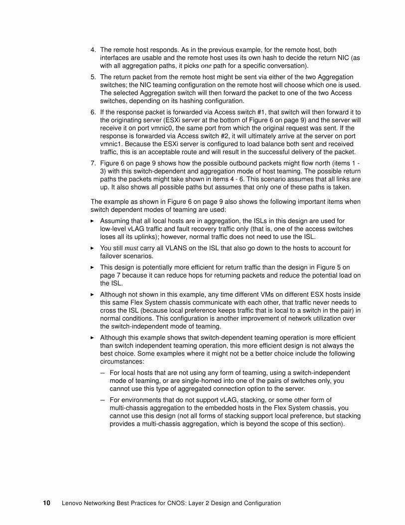
4. The remote host responds. As in the previous example, for the remote host, both interfaces are usable and the remote host uses its own hash to decide the return NIC (as with all aggregation paths, it picks one path for a specific conversation).
5. The return packet from the remote host might be sent via either of the two Aggregation switches; the NIC teaming configuration on the remote host will choose which one is used. The selected Aggregation switch will then forward the packet to one of the two Access switches, depending on its hashing configuration.
6. If the response packet is forwarded via Access switch #1, that switch will then forward it to the originating server (ESXi server at the bottom of Figure 6 on page 9) and the server will receive it on port vmnic0, the same port from which the original request was sent. If the response is forwarded via Access switch #2, it will ultimately arrive at the server on port vmnic1. Because the ESXi server is configured to load balance both sent and received traffic, this is an acceptable route and will result in the successful delivery of the packet.
7. Figure 6 on page 9 shows how the possible outbound packets might flow north (items 1 - 3) with this switch-dependent and aggregation mode of host teaming. The possible return paths the packets might take shown in items 4 - 6. This scenario assumes that all links are up. It also shows all possible paths but assumes that only one of these paths is taken.
The example as shown in Figure 6 on page 9 also shows the following important items when switch dependent modes of teaming are used:
� Assuming that all local hosts are in aggregation, the ISLs in this design are used for low-level vLAG traffic and fault recovery traffic only (that is, one of the access switches loses all its uplinks); however, normal traffic does not need to use the ISL.
� You still must carry all VLANS on the ISL that also go down to the hosts to account for failover scenarios.
� This design is potentially more efficient for return traffic than the design in Figure 5 on page 7 because it can reduce hops for returning packets and reduce the potential load on the ISL.
� Although not shown in this example, any time different VMs on different ESX hosts inside this same Flex System chassis communicate with each other, that traffic never needs to cross the ISL (because local preference keeps traffic that is local to a switch in the pair) in normal conditions. This configuration is another improvement of network utilization over the switch-independent mode of teaming.
� Although this example shows that switch-dependent teaming operation is more efficient than switch independent teaming operation, this more efficient design is not always the best choice. Some examples where it might not be a better choice include the following circumstances:
– For local hosts that are not using any form of teaming, using a switch-independent mode of teaming, or are single-homed into one of the pairs of switches only, you cannot use this type of aggregated connection option to the server.
– For environments that do not support vLAG, stacking, or some other form of multi-chassis aggregation to the embedded hosts in the Flex System chassis, you cannot use this design (not all forms of stacking support local preference, but stacking provides a multi-chassis aggregation, which is beyond the scope of this section).
10 Lenovo Networking Best Practices for CNOS: Layer 2 Design and Configuration

– For environments that require LACP to the host and where some form of communications must take place to the local host before the operating system fully starts so LACP can start (for example, a fresh installation or bare-metal Preboot Execution Environment [PXE] boot), you cannot use this design (the access switches do not pass traffic on a vLAGed LACP port if LACP is not formed).
This issue also is a potential issue with the use of static aggregations to hosts that need PXE boot because before the operating system is loaded, the switch thinks it is one common static aggregation to the host. However, the host (before the operating system load) does not know the switch is in a static aggregation and is expecting any response to come back on the single interface on which it is sending out.
Understanding vLAG Tier IDs
The Tier ID is a mandatory configuration for vLAG. This Tier ID must be the same on a pair of vLAGed switches, but unique between pairs of connecting vLAGed switches. As shown in Figure 2 on page 4, switches 1A and 1B use a common Tier ID. Switches 2A and 2B also use their own common Tier ID, but it is different from the Tier ID that is used by switches 1A and 1B.
The reason connecting vLAGed pairs must use a unique Tier ID is that this Tier ID is used to generate a common shared MAC so that the other side of the vLAG pair thinks it is aggregating with a single device. If two pairs of vLAGed switches (four switches total) are connected with the same Tier ID, they attempt to use the same MAC, which does not work.
This Tier ID generated MAC is derived from a base from a Lenovo reserved range of 08:17:f4:c3:dd:00 - 08:17:f4:c3:de:ff.
The last two bytes are determined by the vLAG Tier ID setting, as shown in Figure 7.
Figure 7 Example vLAG Tier ID settings
vLAG tier ID 1 MAC = 08:17:f4:c3:dd:00vLAG tier ID 2 MAC = 08:17:f4:c3:dd:01vLAG tier ID 512 MAC = 08:17:f4:c3:de:ff
To show the MAC address that is generated by the Tier ID, use the show vlag information command, Figure 8.
Figure 8 Output of “show vlag information” command with generated MAC address
DUTl(config)#show vlag information Global state : enabled VRRP active/active mode : enabled VLAG system MAC : 08:17:f4:c3:dd:00 ISL Information: PCH Ifindex State Previous state -------+-----------+-----------+--------------------------------- 100 100100 Active Inactive
Mis-Match Information: Local Peer -------------+---------------------------+----------------------- Match Result : Match Match Tier ID : 1 1 System Type : G8272 G8272 OS Version : 10.8.x.x 10.8.x.x
11

Role Information: Local Peer -------------+---------------------------+----------------------- Admin Role : Primary Secondary Oper Role : Primary Secondary Priority : 100 200 System MAC : a8:97:dc:dd:ed:Ol a8:97:dc:f7:d5:01
Consistency checking Information: State : enabled Strict Mode : disabled Final Result : pass
FDB refresh Information: FDB is doing refresh with below setting: FDB refresh is configured Bridge FDB aging timer is 300 second(s)
FDB synchronization Information: FDB is being synchronized.
Auto Recovery Interval 250s (Finished)
Startup Delay Interval 90s (Finished)
Health check Information: Health check Peer IP Address: 10.241.38.52 Health check Local IP Address: 10.241.38.51 Health check retry interval: 1 seconds Health check number of keepalive attempts: 2 Health check keepalive interval: 2 seconds Health check status: UP
Peer Gateway State : disabled
VLAG instance 1 : enabled Instance Information PCH ifindex State Previous State Cons Res ----------+-----------+--------------+-----------------+-------- 1000 101000 Formed Remote UP pass
VLAG instance 64 : enabled Instance Information PCH ifindex State Previous State Cons Res ----------+-----------+--------------+-----------------+-------- 2000 102000 Formed Remote UP pass
This MAC address is not used by Virtual Router Redundancy Protocol (VRRP) or communications to end hosts (it is used only to form cross-switch aggregations and to present a common MAC between the vLAGed pair to the other side of the cross-switch aggregation).
If it is using non-vLAG LACP aggregation, the local aggregation uses a MAC from the base system MACs that are available on a switch (as displayed by the show sys-info command) to form the aggregation.
12 Lenovo Networking Best Practices for CNOS: Layer 2 Design and Configuration

Importance of a proper health check network with vLAG
An optional, but strongly recommended, configuration for vLAG is a health check network. Without a health check network configured, the ISL is the only way a vLAGed pair knows that the other switch in the pair is up and in what state. If the ISL goes down without a separate health check network configured, the switches do not know whether the other switch is down or only the ISL path is down. In this state, both switches go active forwarding without knowing what the other switch is doing, and this situation can cause issues with connectivity for attaching devices.
That is why, when a user enables vLAG globally without health check configured, the user is alerted by the importance of using health check connection between the vLAG peers, as shown in Figure 9.
Figure 9 Error message from “vlag enable” command when ISL is not operational
DUTl(config)#vlag enable2018-06-08T13:30:45+02:00 DUTl(cnos:default) %VLAG-4-ENA_WITHOUT_HC_CFG: vLAG health check should be configured to avoid black holing packets when ISL fails
To prevent this situation, an optional health check network can be configured. Owing to the critical function the health check configuration provides, it should be considered mandatory for any production environment.
Consider the following rules for configuring a health check network:
� An IP interface must be configured on each switch in the pair.
It can be used on either the management port or an Ethernet port (both interface VLAN or routed interface are supported for data port). Health check supports both IPv4 and IPv6 addressing, but please note that in the case of IPv6, link local addresses are not permitted, the user has to use the global ones. Examples of IPv6 addressing are shown in Figure 10.
Figure 10 IPv6 addressing displayed and configured for vLAG Health Check
DUTl(config)#show ipv6 interface brief vrf allInterface IPv6 Address/Link-local Address Admin-status Link-status VRFEthernetl/14 fd55:faaf:elab:219d::13 up down 3999 fe80::aa97:dcff:fede:fb01Ethernetl/48 3ffe::1010:2a2a:0:1 up down default fe80::aa97:dcff:fede:ld01Ethernetl/49/1 dd49:ff00::1 up up vrfname fe80::aa97:dcff:fede:le02loopback0 feB0::200:ff:feOO:O up up defaultmgmtO feBO::aa97:dcff:fedd:edOO up up managementvlanl fe80::aa97:dcff:fede:ed01 up up defaultDUTl(config)#vlag hlthchk peer-ip fe80::aa97:dcff:fef8:602 vrf vrfnameError: Health check IP address cannot be link local addressDUTl(config)#DUTl(config)#vlag hlthchk peer-ip dd49:ff00::2 vrf vrfnameDUT1(config)#2018-06-08T14:12:43+02:00 DUTl(cnos:default) %VLAG-5-HC_UP: vLAG Health check is up
These IP interfaces can be shared for a health check and switch management, but a dedicated health check IP interface is preferred.
� Do not configure the IP interfaces for a health check to use the ISL links to communicate with each other. In this case, if the ISL goes down, so does the health check network and
13

the split brain vLAGed pair can still occur. A separate health check network is designed to prevent this situation.
� The IP interfaces that are used for this purpose cannot connect to each other over an aggregation with vLAG. Because the split aggregation of a vLAG pair is considered a single logical interface, any health check packet that goes out the vLAGed aggregation cannot come back to the other switch with the same vLAG aggregation to complete the health check path.
� If the ISL is up, the health check network status has no effect on operation. The health check network plays a part only if the ISL goes down. The following states of the combination of the ISL and health check network status are possible:
– Health check is up and the ISL is up. The vLAG packet passing is 100% operational.
– Health check is down and the ISL is up. The vLAG packet passing is 100% operational, but there is no protection from an ISL failure if the ISL goes down.
– Health check is down and the ISL is down. Split brain operation occurs and both switches are forwarding. This failure of two components is considered a double fault, which often is not considered when redundant designs are built.
– Health check is up and the ISL is down. This situation is why the health check network is important. Consider the following points:
• In this case, the primary VLAG member keeps all links forwarding and the secondary vLAG member error-disables all aggregations that are configured to use vLAG.
• This configuration is critical to ensure a stable environment when an ISL failure occurs.
• When the ISL goes back up, the switches automatically return to normal vLAG operation after a brief time to ensure stability.
� Health check is used also in conjunction with vLAG auto-recovery functionality – at boot, in case the ISL doesn’t come up or fails, the vLAG switch determines the status of the peer switch through Health check. If the peer is operational, the switch continues to keep its vLAG ports in err-disabled state. If the vLAG peer is not detected as functional, the switch assumes the role of the primary and then transitions all of its vLAG ports to the up state.
� Other health check related parameters, shown in Figure 11, can be configured based on the customer environment but it is recommended to use the default ones (keep-alive messages are exchanged every 5 seconds, vLAG peer is considered down if the local switch doesn’t receive a reply to 3 consecutive hello messages with a 30 seconds retry interval).
Figure 11 Configurable Health Check parameters
DUTl(config)#vlag hlthchk? keepalive-attempts Configure VLAG health check number of keepalive attempts keepalive-interval Configure VLAG health check keepalive interval peer-ip Configure VLAG health check peer-ip retry-interval Configure VLAG health check connection retry interval
14 Lenovo Networking Best Practices for CNOS: Layer 2 Design and Configuration
ISL considerations
The ISL is a special and important component for a vLAG environment and has the following unique requirements:
� The ISL must be some form of aggregation (LACP or static). In general, LACP is preferred, owing to the nature of LACP to protect from misconfiguration or miscabling. However, static aggregations work for this purpose.
� The ISL should always be a minimum of two physical links.
Single link aggregation can be configured and used, but it is not advised because it becomes a single point of failure for the vLAG.
It is also possible to take a QSFP/QSFP28 port, set it to 4x10Gb/4x25G/2x50G mode, set an aggregation across that, and use a single QSFP+/QSFP28-to-QSFP+/QSFP28 cable to carry that aggregation. This configuration is also not advised because, although logically it is four different 10/25/50Gb ports, it is using a single physical cable and that single cable becomes a single point of failure.
� Although it is possible to use 1 Gb ports for the ISL and that setting is okay for switches that are primarily 1 Gb, use 10 Gb or higher bandwidth links for this ISL aggregation to ensure proper performance if the switch is primarily a 10/25/40/50/100 Gb switch.
� Sizing of the ISL path is not a simple topic because it depends on the number and speed of uplinks and downlinks, the host bandwidth requirements, and how the hosts are configured for teaming (as described in , “Understanding packet flow in a vLAG environment” on page 3).
One method for sizing the ISL is to create the ISL aggregation to be equal to the bandwidth of the vLAG aggregation uplinks out of a specific vLAGed pair. For example, if a pair of vLAG switches each has 4 x 10 Gb uplinks that create an 8 x 10 Gb vLAG aggregation that is headed upstream, create a 4 x 10 Gb ISL (50% of the total uplink capacity). The logic is that if one side loses all uplinks, it has an equal size path over to the partner switch of the vLAGed pair through the ISL. Consider the following points:
– This 50% might be considered excessive because you can saturate the uplinks of the other switch, but it depends on how much bandwidth is normally in use.
– The numbers that are provided in this section are limited by the total number of available uplinks for use for vLAGed aggregation uplinks and the ISL aggregation; therefore, it might not be practical for every environment.
ISL will always be forwarding even if the root bridge is not in vLAG switch so in this case, the user may see two root ports in spanning tree information on the switch.
An ISL LACP port-channel must be configured in LACP suspend-individual mode (starting CNOS 10.8 release this is the default state for a LACP port-channel). If it is not so, the user is not allowed to do the configuration. This restriction is needed for the case when STP is disabled and some network issues may appear that would make the vLAG peers not to negotiate properly the LACP aggregation and so the lacp members would become individual links leading to a traffic loop appeared between the 2 vLAG switches.
Note that suspend-individual prevents a member of an LACP port channel from forwarding traffic when the LACP protocol fails and that port is suspended when it is placed in individual mode.
15

A sample configuration fragment and the error message generated if the port-channel is not properly configured are shown in Figure 12.
Figure 12 Configuration and diagnostic for improper setting of “suspend-individual”
DUTl(config)#sh running-config interface port-channel 100!interface port-channellOO no lacp suspend-individual switchport mode trunk switchport trunk native vlan 10 switchport trunk allowed vlan 1-500!DUTl(config)#vlag isl port-channel 100% ERROR: interface port-channel polOO has individual on, it is not allowed for vLAG ISL.DUTl (config)#
Once at least one vLAG instance goes to the Formed state, MAC learning on ISL port-channel is automatically disabled no matter the user config is and from now on, all MAC entries appeared in mac-address-table learned over ISL port-channel are added based on vLAG FDB synchronization. The user is alerted by this fact through the syslog output shown in Figure 13.
Figure 13 Alert messages when a vLAG instance is successfully formed
DUT2(config)#2018-06-08T15:38:22+02:00 DUT2(cnos:default) %NSM-5-IFM_LINK_UP: Link up on interface Ethernetl/49/22018-06-08T15:38:22+02:00 DUT2(cnos:default) %NSM-5-IFM_LINK_UP: Link up on interface Ethernetl/49/32018-06-08T15:38:22+02:00 DUT2(cnos:default) %NSM-5-IFM_LINK_UP: Link up on interface Ethernetl/49/42018-06-08T15:38:22+02:00 DUT2(cnos:default) %NSM-5-IFM_LINK_UP: Link up on interface Ethernetl/50/12018-06-08T15:38:22+02:00 DUT2(cnos:default) %NSM-5-IFM_LINK_UP: Link up on interface Ethernetl/50/22018-06-08T15:38:22+02:00 DUT2(cnos:default) %NSM-5-IFM_LINK_UP: Link up on interface Ethernetl/50/32018-06-08T15:38:22+02:00 DUT2(cnos:default) %NSM-5-IFM_IF_UP: state up on interface polOO2018-06-08T15:38:22+02:00 DUT2(cnos:default) %VLAG-5-ISL_STATE: VLAG ISL state change to Inactive2018-06-08T15:38:23+02:00 DUT2(cnos:default) %NSM-5-IFM_LINK_UP: Link up on interface Ethernetl/50/42018-06-08T15:38:27+02:00 DUT2(cnos:default) %VLAG-5-ISL_STATE: VLAG ISL state change to Active2018-06-08T15:38:33+02:00 DUT2(cnos:default) %VLAG-5-INST_STATE: vLAG instance 1 state change to Formed2018-06-08T15:38:33+02:00 DUT2(cnos:default) %NSM-5-VLAG....MAC_LEARN_CTRL: MAC learning disabled for ISL port-channel 1002018-06-08T15:38:33+02:00 DUT2(cnos:default) %VLAG-5-INST_STATE: vLAG instance 64 state change to Formed
ISL is used also at boot in conjunction with vLAG start-up delay functionality – when vLAG switch reboots, all vLAG ports are kept in the err-disabled state during the auto-recovery interval. The startup delay timer is started only when the ISL is Active; when this timer expires, vLAG ports are brought up.
In the current design, the frames received over ISL port-channel will never be forwarded to vLAG port-channel but only to non-vLAG ports. The reason for doing this is to avoid packet duplication.
Design considerations for vLAG
Consider the following points regarding vLAG:
� Owing to the fact that vLAG often is used to create non-looped designs; it is not uncommon to disable spanning-tree globally on a vLAGed pair of switches.
16 Lenovo Networking Best Practices for CNOS: Layer 2 Design and Configuration

� If spanning tree is required, PVRST (default) and MSTP can be used on the vLAG pairs.
� When you are looking at spanning tree (for example, by using the show span command) on a vLAGed pair of switches and the other side of the vLAG aggregation is towards the root, the root bridge appears as being on the uplinks of the vLAG primary switch of the pair; however, the secondary switch appears as both on the uplinks and toward the ISL of the other vLAGed switch. This display is not an indication of an issue. Instead, it is an artifact of how vLAG works and it does not affect operation or forwarding and blocking.
� Check the Application Guide for the switch model and code version in use to see whether there are any specific limitations with vLAG for that release and model.
� When you are using vLAG in a tiered design and the other side is another pair of vLAG switches, vPC, or some form of cross chassis aggregation, an optimal design is to connect at least one link between all four switches in the pair. This configuration is shown in Figure 2 on page 4, where each of the lower switches has a connection to each of both of the upper switches. The alternative is a design where the four links do not cross connect as shown. Both designs work, but the crossed design is more robust during switch failure events.
� When you are upgrading a vLAGed pair of switches, consider the following guidelines:
– Upgrade both vLAG peers with the new OS image; shutdown all vLAG ports on Primary switch so all traffic passes now Secondary switch; reload the primary switch of the vLAG pair first. During that reload, the secondary switch that is running the older code becomes the primary. After the primary is fully operational and forwarding, shutdown all vLAG ports on Secondary switch so all traffic passes now Primary switch; reload the current Primary one (old Secondary). After this last one is fully operational and forwarding, use the show vlag information command to determine the vLAG election and vLAG instances state.
– When you are upgrading vLAGed pairs, it is important to have both switches running the same version of code. Do not upgrade one switch in the pair and leave the switches running for an extended time on different versions of code.
– During the upgrade process using the above steps, we will have a mismatch situation when one switch uses the new OS and the other one uses the old OS image. This is not impacting vLAG functionality, all instances get formed but a syslog appears once at 10 seconds notifying the user about this mismatch scenario.
� Some additional notes about vLAG:
The peer switches negotiate so that one switch is primary and one is secondary. This is done by comparing the switches’ system MAC addresses; the switch with the lower MAC wins. In the event of an ISL failure where both switches are still operational (not a switch failure), the vLAG interfaces on the secondary switch are disabled. This will only work properly if there is a health check in place, as discussed in “Importance of a proper health check network with vLAG” on page 13.
The possible vLAG state values for a vLAG instance are:
– Formed – physical connections from both peer switches are up and carrying traffic.
– Local Up – physical connections from this switch are up but the corresponding members of the instance on the peer switch are down. Traffic can transit the remote switch over the ISL and still reach its destination.
– Remote Up – physical connections from this switch are down but the corresponding members of the instance on the peer switch are up. Traffic can transit this switch via the ISL and still reach its destination.
– Down – the instance is not operating and is not able to carry any traffic.
17

vLAG LACP misconfiguration/mis-cabling
In vLAG topology, LACP misconfiguration or incorrect cabling can cause vLAG to form 2 port-channels which may lead to a network loop. Current vLAG implementation will detect this misconfiguration or cabling errors and will take the following actions, shown in Figure 14:
� Return a level 4 syslog message alerting the user about the error situation
� Move the vLAG LACP port-channel members to suspended state
Figure 14 Diagnostic messages from mis-cabling that results in two distinct port channels
2018-06-llTl0:23:36+02:00 DUTl(cnos:default) %VLAG-5-INST_STATE: vLAG instance 1 state change to Formed2018-06-llTl0:23:36+02:00 DUTl(cnos:default) %LACP-4-VLAG_INST_MISMATCH: LACP port Ethernetl/l's received partner info is mismatched with vLAG instance l's expected one, it will be suspended.2018-06-llTl0:23:36+02:00 DUTl(cnos:default) %LACP-4-VLAG_INST_MISMATCH: LACP port Ethernetl/2's received partner info is mismatched with vLAG instance l's expected one, it will be suspended.2018-06-llTl0:23:36+02:00 DUTl(cnos:default) %NSM-5-IFM_IF_DOWN: State down on interface polOOO2018-06-llTl0:23:37+02:00 DUTl(cnos:default) %VLAG-5-INST_STATE: vLAG instance 1 state change to Remote UP2018-06-llTl0:23:37+02:00 DUTl(cnos:default) %NSM-5-LACP_PORT_SUSPENDED: port Ethernetl/1 of port-channel polOOO is operationally suspended2018-06-llTl0:23:37+02:00 DUTl(cnos:default) %NSM-5-LACP_PORT_SUSPENDED: port Ethernetl/2 of port-channel polOOO is operationally suspended
Once the invalid configuration/error in the topology is corrected, the ports that were suspended due to vLAG misconfiguration will be re-enabled.
Please note that the misconfiguration check is done on vLAG Secondary switch only and so the log appears here only and not on vLAG Primary switch too.
For static port-channels configured in a vLAG instance, the firmware cannot detect the misconfiguration since there are no control packets exchanged between the switches. This is one reason why LACP is preferred over static aggregations.
vLAG config consistency-check
vLAG configuration consistency-check is another protection mechanism used in conjunction with vLAG feature; it ensures that network behaves correctly by checking for incompatible configuration options between the vLAG peers. This is done using the vLAG synchronization protocol.
Each configuration parameter is classified with its associated priority level. Different actions will be applied when an incompatibility is detected based upon the parameter’s priority.
Whenever a high priority parameter is detected as being inconsistent across vLAG peers, a syslog message with a critical severity level is logged and the following actions are taken:
� If the inconsistent parameter is global or related to the ISL, the Link Aggregation Groups (LAGs) of all the vLAG instances on the vLAG Secondary switch are put down in err-disabled state; if the inconsistent parameter is related to the vLAG instance, the LAG associated with that instance is put into the err-disabled state. After the inconsistency is fixed, respectively LAG/LAGs are brought up and all vLAG instances recover to a formed state
� If the detected inconsistency refers to a low priority parameter, by default the switch will only record a syslog message with a warning severity level for that inconsistency. To allow the switch to perform the same actions as when dealing with high priority parameters, strict consistency checking must be manually enabled.
18 Lenovo Networking Best Practices for CNOS: Layer 2 Design and Configuration

vLAG configuration consistency-check is enabled by default and can be disabled manually based on user choice. It has to be enabled on both vLAG peer switches in order to work properly.
The monitored parameters, their priorities and the vLAG peer’s config consistency-check results can be observed using the commands shown in Figure 15.
Figure 15 vLAG information and status display
DUT2(config)#show vlag information Global state : enabled VRRP active/active mode : enabled VLAG system MAC : 08:17:f4:c3:de:fe ISL Information: PCH Ifindex State Previous state -------+-----------+-----------+--------------------------------- 100 100100 Active Inactive
Mis-Match Information: Local Peer -------------+---------------------------+----------------------- Match Result : Match Match Tier ID : 511 511 System Type : NE2572 NE2572 OS Version : 10.8.x.x 10.8.x.x
Role Information: Local Peer -------------+---------------------------+----------------------- Admin Role : Secondary Primary Oper Role : Secondary Primary Priority : 200 100 System MAC : a4:8c:db:ba:76:0l a4:8c:db:ba:79:0l
Consistency checking Information: State : enabled Strict Mode : disabled Final Result : pass
FDB refresh Information: FDB is doing refresh with below setting: FDB refresh is configured Bridge FDB aging timer is 1800 second(s)
FDB synchronization Information: FDB is being synchronized.
Auto Recovery Interval 240s (Finished)
Startup Delay Interval 60s (Finished)
Health check Information: Health check Peer IP Address: 10.241.38.232 Health check Local IP Address: 10.241.38.233 Health check retry interval: 30 seconds Health check number of keepalive attempts: 3 Health check keepalive interval: 5 seconds Health check status: UP
Peer Gateway State : disabled
19

VLAG instance 1 : enabled Instance Information PCH ifindex State Previous State Cons Res ----------+-----------+--------------+-----------------+-------- 1000 101000 Formed Remote UP pass
VLAG instance 30 : enabled Instance Information PCH ifindex State Previous State Cons Res ----------+-----------+--------------+-----------------+-------- 3000 103000 Formed Remote UP pass
VLAG instance 64 : enabled Instance Information PCH ifindex State Previous State Cons Res ----------+-----------+--------------+-----------------+-------- 2000 102000 Formed Remote UP pass
DUT2(config)#sho vlag config-consistency "N/A": Unavailable value "-" : Digest value, detail value dump by detail show command item Prio result local remote ------------------------------------------------------------------------------ s1s mac learn high pass enable enable global tag native high pass disable disable ISL port mode high pass trunk trunk ISL access vlan high pass 1 1 ISL native vlan high pass 10 10 ISL allowed vlan high pass - - ISL tag native high pass none none ISL dot1q tunnel high pass disable disable ISL egress tagged vlans high pass - - stp mode high pass rapid-pvst rapid-pvst stp path cost high pass long long mst region name high pass - - mst region version high pass 0 0 mst inst mapping high pass - - mst max-age low pass 20 20 mst max-hops low pass 20 20 mst hello time low pass 2 2 mst forward time low pass 15 15
DUT2(config)#sho vlag config-consistency detail "N/A": Unavailable value "-" : Digest value, detail value dump by detail show command item Prio result local remote ------------------------------------------------------------------------------ sys mac learn high pass enable enable global tag native high pass disable disable ISL port mode high pass trunk trunk ISL access vlan high pass 1 1 ISL native vlan high pass 10 10 ISL allowed vlan high pass ec df f3 65 df 4f 3d ec df f3 65 df 4f 3d 72 46 9d a2 3c aa 37 72 46 9d a2 3c aa 37 b6 e6 b6 e6 ISL tag native high pass none none ISL dotlq tunnel high pass disable disable ISL egress tagged vlans high pass 6e 6f 6e 65 00 00 00 6e 6f 6e 65 00 00 00 00 00 00 00 00 00 00 00 00 00 00 00 00 00
20 Lenovo Networking Best Practices for CNOS: Layer 2 Design and Configuration

00 00 00 00 stp mode high pass rapid-pvst rapid-pvst stp path cost high pass long long mst region name high pass b8 10 61 e7 10 8c aa b8 10 61 e7 10 8c aa de 12 61 64 77 ef a9 de 12 61 64 77 ef a9 eb 3b eb 3b mst region version high pass 0 0 mst inst mapping high pass ac 36 17 7f 50 28 3c ac 36 17 7f 50 28 3c d4 b8 38 21 dB ab 26 d4 b8 38 21 dB ab 26 de 62 de 62 mst max-age low pass 20 20 mst max-hops low pass 20 20 mst hello time low pass 2 2 mst forward time low pass 15 15
local digest item value: ISL allowed vlan: 1-255 ISL egress tagged vlans: 1-9,11-255 mst region name: mst inst mapping: Inst vlans mapped ---- ---------------------------------------------------------------- 0 1-4094
DUT2(config)#show vlag instance 1 config-consistency "N/A": Unavailable value "-" : Digest value, detail value dump by detail show command item Prio result local remote ------------------------------------------------------------------------------ port mac 1earn high pass enable enable port mode high pass trunk trunk access vlan high pass 1 1 native vlan high pass 10 10 allowed vlan high pass - - tag native high pass none none agg type high pass lacp lacp suspend-individual low pass enable enable dot1q tunnel high pass disable disable egress tagged vlans high pass - - private-vlan high pass - - stp port mode high pass enable enable stp port Path cost high pass auto auto stp port Type high pass disable disable stp bpdu filter low pass disable disable stp BPDU guard low pass disable disable stp port loop guard low pass disable disable stp port root guard low pass disable disable stp link type low pass auto auto stp port priority low pass 128 128 mst port cost high pass - - mst port priority low pass - -
DUT2(config)#show vlag instance 1 config-consistency detail "N/A": Unavailable value "-" : Digest value, detail value dump by detail show command VLAG instance 1 : item Prio result local remote ------------------------------------------------------------------------------ port mac learn high pass enable enable port mode high pass trunk trunk
21

access vlan high pass 1 1 native vlan high pass 10 10 allowed vlan high pass ec df f3 65 df 4f 3d ec df f3 65 df 4f 3d 72 46 9d a2 3c aa 37 72 46 9d a2 3c aa 37 b6 e6 b6 e6 tag native high pass none none agg type high pass lacp lacp suspend-individual low pass enable enable dot1q tunnel high pass disable disable egress tagged vlans high pass 6e 6f 6e 65 00 00 00 6e 6f 6e 65 00 00 00 00 00 00 00 00 00 00 00 00 00 00 00 00 00 00 00 00 00 private-vlan high pass 56 d7 9a ef 02 b4 75 56 d7 9a ef 02 b4 75 74 le fl Of be 77 08 74 le fl Of be 77 08 c7 fe c7 fe stp port mode high pass enable enable stp port Path cost high pass auto auto stp port Type high pass disable disable stp bpdu filter low pass disable disable stp BPDU guard low pass disable disable stp port loop guard low pass disable disable stp port root guard low pass disable disable stp link type low pass auto auto stp port priority low pass 128 128 mst port cost high pass c7 19 f2 95 45 6b 84 c7 19 f2 95 45 6b 84 ld 55 fc 6c cd 7e 81 ld 55 fc 6c cd 7e 81 le 8d le 8d mst port priority low pass c7 19 f2 95 45 6b 84 c7 19 f2 95 45 6b 84 ld 55 fc 6c cd 7e 81 ld 55 fc 6c cd 7e 81 le 8d le 8d
local digest item value: allowed vlan: 1-255 egress tagged vlans: 1-9,11-255 mst port cost : mst port priority:
As expected, vLAG configuration config-consistency works only when ISL is active. When ISL is down, the 2 vLAG peers cannot synchronize the information and this is reflected also in the output of config consistency-check as shown in Figure 16.
Figure 16 vLAG consistency check fail when ISL is down
DUT2(config)#sho vlag config-consistency "N/A": Unavailable value "-" : Digest value, detail value dump by detail show command item Prio result local remote ------------------------------------------------------------------------------ s1s mac learn high N/A enable N/A global tag native high N/A disable N/A ISL port mode high N/A trunk N/A ISL access vlan high N/A 1 N/A ISL native vlan high N/A 10 N/A ISL allowed vlan high N/A - N/A ISL tag native high N/A none N/A ISL dot1q tunnel high N/A disable N/A ISL egress tagged vlans high N/A - N/A stp mode high N/A rapid-pvst N/A stp path cost high N/A long N/A mst region name high N/A - N/A
22 Lenovo Networking Best Practices for CNOS: Layer 2 Design and Configuration

mst region version high N/A 0 N/A mst inst mapping high N/A - N/A mst max-age low N/A 20 N/A mst max-hops low N/A 20 N/A mst hello time low N/A 2 N/A mst forward time low N/A 15 N/A
DUT2(config)#show vlag instance 1 config-consistency detail "N/A": Unavailable value "-" : Digest value, detail value dump by detail show command VLAG instance 1 : item Prio result local remote ------------------------------------------------------------------------------ port mac learn high N/A enable N/A port mode high N/A trunk N/A access vlan high N/A 1 N/A native vlan high N/A 10 N/A allowed vlan high N/A ec df f3 65 df 4f 3d N/A 72 46 9d a2 3c aa 37 b6 e6 tag native high N/A none N/A agg type high N/A lacp N/A suspend-individual low N/A enable N/A dotlq tunnel high N/A disable N/A egress tagged vlans high N/A 6e 6f 6e 65 00 00 00 N/A 00 00 00 00 00 00 00 00 00 private-vlan high N/A 56 d7 9a ef 02 b4 75 N/A 74 le fl Of bc 77 08 c7 fe stp port mode high N/A enable N/A stp port Path cost high N/A auto N/A stp port Type high N/A disable N/A stp bpdu filter low N/A disable N/A stp BPDU guard low N/A disable N/A stp port loop guard low N/A disable N/A stp port root guard low N/A disable N/A stp link type low N/A auto N/A stp port priority low N/A 128 N/A mst port cost high N/A c7 19 f2 95 45 6b 84 N/A 1d 55 fc 6c cd 7e 81 lc 8d mst port priority low N/A c7 19 f2 95 45 6b 84 N/A ld 5 5 fc 6c cd 7e 81 lc 8d
local digest item value: allowed vlan: 1-255 egress tagged vlans: 1-9,11-255 mst port cost: mst port priority:
23

vLAG Peer Gateway
There are multiple OS implementations that allow the servers to use the source MAC address of a received packet as the destination MAC for the response packet instead of a gateway MAC address. In a vLAG environment, this will result in the server using the physical MAC address of the vLAG switch instead of the gateway MAC. It is desirable to use the gateway MAC address, which usually is the VRRP MAC shared between both vLAG peer switches.
The vLAG Peer Gateway feature allows the vLAG switches to forward to downstream vLAG ports all packets that are received and which have the DMAC address equal to the peer vLAG switch MAC address, instead of sending them to the other switch via the ISL). This allows a vLAG switch to act as a gateway for traffic addressed to its vLAG peer by enabling local forwarding of such traffic.
By default, the vLAG Peer Gateway is disabled. For it to function properly, it must be enabled on both vLAG peers. The command that controls this function is [no] vlag peer-gateway.
vLAG and L3 protocols
In the current implementation, vLAG switches cannot be used inside the L3 domain. Therefore, neither static, nor dynamic routing is supported inside a vLAG domain.
Routing protocols can be running on each vLAG switch, but there is no mechanism to make them work as one logical protocol peer. The L3 forwarding tables are not synchronized between vLAG peers, therefore, they will likely have different L3 routes.
However, to enable the usage of VLAG switches as a gateway, the use of VRRP active-active mode is supported. Both primary and secondary switches can forward the L3 traffic in the given virtual router instance, independent of their VRRP state (master or backup virtual router).
Static and dynamic routing protocols can run on vLAG switches but not on those VLANs which are members of the L2 vLAG domain. Those VLANs should be enabled on the links that connect to the L3 domain.
vLAG switches can work in 2 modes in a 2- tier vLAG topology known as 4xvLAG+VRRP configuration:
� vLAG VRRP Active (Full Active-Active HAA) mode – in this mode, all vLAG switches are in IP active state. This means that all four switches will install the Layer 3 routing entry regardless of their virtual router role or whether their vLAG peer is the master or backup virtual router. By default, the vLAG VRRP works in this mode
� vLAG VRRP Passive (Half Active-Active HAA) mode – in this mode, vLAG VRRP backup will check if the vLAG peer of a switch is the VRRP master. If neither the vLAG primary nor secondary is the VRRP master, then vLAG VRRP backup will not install L3 routing entries on this switch. Only the VRRP Master and its vLAG peer backup VRRP are in IP active state if the VRRP Master should go down, the newly elected VRRP Master and its vLAG peer backup VRRP switch will be in IP active state.
This design is useful in an environment where there are two distinct facilities, one of which is for backup or disaster recovery.
24 Lenovo Networking Best Practices for CNOS: Layer 2 Design and Configuration

Layer 2 failover
Layer 2 failover on Lenovo switches works with NIC teaming on the servers to prevent a black hole when all uplinks out of a switch go down. This feature is important in embedded environments but also applies to stand-alone Lenovo switches. When the uplinks out of an embedded switch go down in an embedded environment, the server-facing ports normally are still up. In this situation, teaming on the servers does not know that the path via the uplinks went down and that it needed to failover. When failover is enabled on the switches, the switch also shuts down the server facing ports when the uplinks being monitored go down, which alerts NIC teaming that this switch no longer has a path out and failing over.
After the monitored uplinks are restored, failover automatically re-enables the server facing ports, which informs NIC teaming that this path is available again. Failover is triggered not only on the monitored uplinks being in a down state but also if the monitored uplinks are all in a spanning-tree blocked state or disabled by LACP due to a mismatch. In other words, if the monitored links are not able to carry traffic then failover would be triggered.
IGMP Snooping considerations
Internet Group Management Protocol (IGMP) snooping is a feature to control multicast flows in Layer 2 networks. By default, IGMP snooping is enabled on Lenovo switches with CNOS, which enables limiting multicast flows to only those devices and ports that need to see a specific stream.
Consider the following points when you are implementing IGMP snooping on Lenovo switches:
� All Lenovo switches support IGMP V1, V2, and V3.
� Some other features might limit the use of IGMP snooping. It is important to check the Application Guide for the product and feature to ensure IGMP use is not restricted. For example, consider the following points:
� The maximum number of multicase group entries is currently 8191 when switches run CNOS. If an environment includes multicast routers, they can be used to perform keep-alive queries and keep multicast groups from expiring. If you are working in an environment where only local multicast is being used (no mrouters), the IGMP snooping querier feature of Lenovo switches can be enabled to provide this keep-alive query service that is normally provided by an mrouter.
Link aggregation
This section provides information about link aggregation. Lenovo switches support static (PortChannel) and dynamic (LACP) link aggregation modes. The key difference between these modes is that static aggregation is unconditional and always in effect on ports where it is configured. Dynamic aggregation uses an interactive protocol between both devices, which helps protect against cabling errors and other errors that can cause unwanted effects.
In general, dynamic aggregation with LACP is preferred. It is standards-based and supported by all network equipment vendors. Some server operating systems and utilities from NIC vendors also support LACP. There are some conditions where static link aggregation should be considered when the server operating system (or other software) that is being connected to does not support LACP.
25

Static PortChannelThis section describes Static PortChannel, which has the following form:
interface ethernet 1/<x> channel-group <y> mode on
Ports in the same channel must have the same attributes in the following areas or the channel does not form successfully:
� VLAN membership, including native VLAN� Spanning Tree options� Bandwidth (ports with different bandwidths cannot be channeled together)
LACP (dynamic) PortChannelThis section describes LACP (dynamic) PortChannel.
LACP channels are configured primarily on lists or ranges of ports, where the LACP key and state are configured, and involves the following commands:
interface ethernet 1/<x> channel-group <y> mode active|passive
The channel group number will be used as the local LACP key number and must be the same on all ports to be put in a common aggregation. Mode active often is the preferred mode when enabling LACP.
Trunk hashing configuration
A set of aggregated links does not completely match the performance characteristics of a single link with the same total bandwidth. This issue occurs because all link aggregation techniques use an algorithm to determine which physical link is to be used to transmit a packet. These algorithms are referred to as hashing algorithms. When two devices are connected by a set of aggregated links, each side uses a hashing algorithm and each side can configure that algorithm independently from the other side.
The purpose of these options is to allow the choice of an option that best provides even allocation of traffic across the available aggregated links. The reason that aggregated links might not deliver the same performance as a single link is that the traffic can be unevenly allocated across the available links, which saturates some of them and leaving others nearly idle.
Lenovo switches allow the hashing of traffic on the physical ports that are members of a port channel using several different metrics. The command to accomplish this is:
port-channel load-balance Ethernet XXXX
Where XXXX is one of the below options shown in Figure 17 on page 27. These options enable hashing based on options at Layers 2-4 as well as options which only apply for FCoE traffic. This command is entered in global configuration mode and applies to all port-channels; there is not currently an option to use different hashing for different port channels.
26 Lenovo Networking Best Practices for CNOS: Layer 2 Design and Configuration

Figure 17 Port-channel hashing options
Measuring traffic on parallel linksTo choose the appropriate option, a process or trial-and-error often is used unless good information about traffic characteristics is available. This process includes making a best guess initial choice of options and measuring the traffic flowing over the parallel links to determine whether it is imbalanced to the point that another option is better.
The following commands can be used to gather this information:
show interface <id|list|range> counters <brief|detailed>show port-channel traffic interface port-channel <x>
Changing the parameters on a switch influences only the packets that are egressing from that switch. The device at the other end, which might be from a different vendor, needs a similar configuration to ensure that traffic coming into a Lenovo switch is well-balanced across a link aggregation group.
Options for LACP configuration
This section describes the options for LACP configuration.
LACP timersThe LACP timeout option can be set to long (30 seconds, which is the default setting), or short (1 second). Most vendors also default to long, but a few (for example, Juniper) default to short. For proper operation, both sides must agree on the same LACP timers. Based on several factors, it is best to use long timers whenever possible. The use of short timers on both sides can affect switch stability, and result in false positives for LACP failure, which leads to less than stable operation. This parameter is set once per interface.
Suspend-individualThis option on a port-channel command configures an LACP PortChannel so that if an individual port does not receive LACPDU packets from its counterpart on the other device, the port goes into a suspended state and not pass any traffic. In general, this result is desirable and is the default option; if it is disabled (no suspend-individual), after a period the port functions as though it were an individual port and not part of any aggregation.
The primary case when this option is not helpful is on server-facing ports where the server uses a form of network boot (PXE, BOOTP, and so on). Because the code that provides the
#port-channel load-balance eth ? destination-ip Load distribution on the destination IP address destination-mac Load distribution on the destination MAC address destination-port Load distribution on the destination TCP/UDP port fcoe-sid-did Load distribution on the FCoE sid and did fcoe-sid-did-oxid Load distribution on the FCoE sid, did and oxid fcoe-sid-did-oxid-rxid Load distribution on the FCoE sid, did, oxid, and rxid source-dest-ip Load distribution on the source and destination IP address source-dest-mac Load distribution on the source and destination MAC address source-dest-port Load distribution on the source and destination TCP/UDP port source-interface Load distribution on the source ethernet interface source-ip Load distribution on the source IP address source-mac Load distribution on the source MAC address source-port Load distribution on the source TCP/UDP port
27

LACP protocol is typically not available before boot, the port does not pass any traffic and the network boot fails.
As of CNOS 10.8, suspend-individual is enabled by default, but it can still be disabled.
LACP configurationThe use of a systematic scheme for numbering LACP keys can be useful for debugging.
The LACP key is derived from the port-channel number as specified in the channel-group command which is shown in Figure 18 below.
Because LACP keys have only local significance, the device at the other end of the links can use a key appropriate for the ports that are used on its side, although it might facilitate troubleshooting for both sides to use the same number.
Sample LACP configurationsFigure 18 shows the general configuration for using LACP.
Figure 18 Typical LACP configuration
Although passive mode is also supported, there is no advantage in using it. If both sides of a link aggregation use active mode, the side that starts the protocol first takes the active role. If both sides use the passive option, the LACP protocol does not complete and the links do not pass traffic.
The following commands can be used as needed.
Figure 19 Suspend-individual option
Spanning Tree Protocol
STP is a commonly used protocol to actively block network loops. The consequences of a network loop are dramatic, and usually result in significant network outages. The use of STP can protect your network from these potential outages by providing automatic activation of redundant paths.
Although STP is one of the most misunderstood and problematic configuration elements in networking, successful implementation can be achieved if you are careful and follow a few simple rules that are described in this section. STP is an active protocol, which means that transmissions that occur on the wire and missteps in the configuration can result in inefficient network paths and potential network outages. Therefore, STP configuration changes should be conducted during scheduled network downtimes.
interface Ethernet <1/<x> or list or range>channel-group <x> mode <active|passive>
interface port-channel <x>[no] lacp suspend-individual
28 Lenovo Networking Best Practices for CNOS: Layer 2 Design and Configuration

STP fundamentals
STP was originally defined in the IEEE 802.1D standard, which defined a single instance of STP. This standard describes how multiple Layer 2 bridges (typically switches) can interact to define a spanning tree blocking any redundant paths between network nodes.
When you configure STP, you must consider the hierarchy of the spanning tree. The tree has a root bridge with a subtree below it. Then, each subtree has a designated root bridge that points back to the root bridge. The subtrees fan out all the way down to the edge devices.
Figure 20 shows an example network.
Figure 20 Example network
As shown in Figure 20, multiple loops are in the network and, if nothing is done to block the loops, a single broadcast packet (such as an ARP) can rapidly overrun the network. This issue occurs because each broadcast packet replicates two or more times while it is being flooded by each switch. STP blocks the redundant links to prevent the network loops through a negotiation. This negotiation uses a packet called a Bridge Protocol Data Unit (BPDU) that is transmitted by the switches.
To configure STP, you must first determine which switch should be the root bridge, which often is the core of the network. In the example, this switch is A1 or A2. Then, you must determine each level of the tree down to the edge (in this example, C1-C8).
After you determine the hierarchy of the tree, you must determine the bridge priority to use at each level that is used for STP to determine the root of the tree. Bridge priorities have a value of 0 - 61,440 incremented in intervals of 4096 where a switch with the lowest bridge priority is selected as the root bridge. If the bridge priority is equal, the switch with the lower MAC address is the root.
If you want a switch to be the root bridge, set the bridge priority to 0 but exercise caution when this setting is used in a network. By default, most switches set their default bridge priority to 32768, which includes the RackSwitch™ TOR switches.
C1 C2 C5
B1 B2
A1 A2
B3 B4
C4 C6 C8C3 C7
29

STP then uses the bridge priority to determine the designated root bridge for each loop that is the preferred path to the root bridge or the tree’s root bridge. The switch that is determined to be the furthest path from the root bridge blocks ports by placing them to discarding to eliminate the network loops. Figure 21 shows an example network with bridge priorities.
Figure 21 Example network with bridge priorities
Figure 21 displays the example network with some example bridge priorities configured, assuming that the subtree is inserted at the edge of the network. Devices C1 - C8 are edge devices; therefore, the bridge priority should be set to 61440. The next layers should have a primary and secondary bridge configured so each pair should be set to adjacent bridge priorities. B1 - B4 are configured with bridge priorities 53248 and 57344 and switches A1 and A2 use the bridge priorities of 45056 and 49153. These values are deterministic on the target network.
If the preceding bridge priorities are used, each level of the tree determines the designated bridge for each level (indicated by the gray box in Figure 21), which has the preferred path to the root bridge. The non-preferred paths are blocked (designated by X in Figure 21) on the switch that is furthest from the root bridge. The alternative paths are marked by dashed lines in Figure 21 and all loops are blocked.
Although there are many other elements to STP, the bridge priorities are the most important elements to understand because this element is the primary element that is used to form the hierarchy of the spanning tree. When any link on a port changes, communication between devices in the spanning tree might be interrupted while STP renegotiates the best path to the root bridge, which is called STP convergence. This concept is important because if you reboot a device on the LAN, network traffic can be interrupted.
The STP standard evolved as the Layer 2 protocols evolved to include support for protecting loops in multiple VLANs. One such standard developed by Cisco is called Per VLAN Spanning Tree (PVST) and Per VLAN Spanning Tree Plus (PVST+) where a spanning tree instance is created for each VLAN. Each STP instance uses a BPDU that is tagged with the VLAN ID to negotiate the STP protocol. PVST/PVST+ STP instance 1 uses an untagged BPDU, which is compatible with the IEEE standard STP. STP instance 1 is the only instance that can control more than one VLAN because all of the other instances use the unique VLAN ID to tag the BPDU.
C1 61440
C2 61440
C5 61440
B1 53248
B2 57344
A1 45056
A2 49153
B3 53248
B4 57344
C4 61440
C6 61440
C8 61440
C3 61440
C7 61440 X X X X
X X X X X X X X
X X X X X X
30 Lenovo Networking Best Practices for CNOS: Layer 2 Design and Configuration

Rapid STP (RSTP) defined by IEEE 802.1w evolved from STP to significantly reduce the amount of time it takes for a network to converge from 40 to 50 seconds down to 6 seconds or less. RSTP is compatible with an earlier version with STP and is incorporated into the IEEE 802.1D-2004 standard. Cisco extended PVST/PVST+ to include RSTP extensions with Rapid Per VLAN Spanning Tree (RPVST) or Per VLAN Rapid Spanning Tree (PVRST).
RSTP is no longer supported on Lenovo switches, but equivalent capability can be obtained via PVRST or MSTP when only one VLAN is in use.
Finally, the IEEE community added Multiple Spanning Tree Protocol (MSTP), which was originally defined in the IEEE 802.1s standard and later merged into IEEE 802.1Q-2005. MSTP is similar to PVRST in that it contains multiple STP instances. However, unlike PVRST, MSTP allows multiple VLANs to be defined in all of the STP instances. MST also limits the number of STP instances to 64 with IDs 0 - 64 and maps these into a single BPDU to provide less processing overhead than PVRST, which uses a BPDU for each VLAN.
In summary, the following major implementations of STP are available:
� Per VLAN Rapid Spanning Tree (PVRST)� Multiple Spanning Tree Protocol (MSTP)
Another STP mode to consider is to disable STP. The way switches function with STP disabled is not defined in IEEE 802.1D-2004, so care should be taken to understand how the device works in this mode. The following section describes how this mode works in the Lenovo switches.
Each of these modes is different and it is important to select the proper STP mode (type) when integrating into a network. Network instability and outages occur if the same STP mode is not used on every network device.
How STP is implemented on the Lenovo switches
The Lenovo switches implement three STP modes that follow the STP protocols that are described in “STP fundamentals” on page 29. The following sections describe how the modes are implemented by Lenovo.
Per VLAN Rapid Spanning TreePVRST is the default STP mode in the switch. The following command is used to enable PVRST:
spanning-tree mode rapid-pvst
If spanning-tree is enabled then an instance is automatically created for each VLAN. Spanning-tree can be selectively disabled for ports or VLANs as desired.
The VLAN’s STP bridge priority is configured by using the command:
spanning-tree vlan <id> priority <PRIORITY>
In this example, GROUP is the STP group and PRIORITY is the STP priority (0 - 61440). The priority is required to be a multiple of 4096, as described in “STP fundamentals” on page 29. For example, if 61000 is selected, an error message will be generated.
Multiple Spanning TreeMSTP can be enabled by using the following command:
spanning-tree mode mst
31

Before MSTP mode can be selected, the name and revision number must be configured with the same value as all other devices in the network. The name is a character string of up to 32 case-sensitive characters and the revision is a value of 0 - 65535 where the default value is 1. Most vendors set the default revision number as 1, except for Cisco.
The following command is used to configure the name and revision:
spanning-tree mst configurationname NAME_STRINGrevision REVISION_NUMBERexit
The MSTP configuration can be validated by using the command show spanning-tree mst configuration.
For MSTP to properly balance the trees, the VLANs must be mapped to the same instances throughout the network. The assignment is done by using the following command:
spanning-tree mst configurationinstance INSTANCE vlan VLANSexit
In this example, INSTANCE is the MSTP instance 0 - 64 and VLANS is the range of VLANS to be assigned. The VLAN mappings can be validated by comparing the MSTP Digest, which is the common calculated value defined by the MSTP standard and used by all devices in the tree.
The MSTP instance bridge priorities function the same way as in all of the STP standards and can be set by using the following command:
spanning-tree mst INSTANCE priority PRIORITY
Disable Spanning TreeSpanning Tree can be globally disabled by using the following command:
spanning-tree mode disable
Globally disabling STP disables all local STP processing on the switch and any BPDU that is received is forwarded as is any other L2 packet, which allows the upstream switches to process all STP control.
Loop Guard
Loop Guard adds protection against network loops that are caused by improperly functioning remote devices with conditions, such as a unidirectional link failure. This feature monitors the BPDUs that are normally received on STP enabled ports and places the port into a loop-inconsistent blocking state if BPDUs are no longer received. After BPDUs are received again, the port is placed back into a normal error-free STP state.
The following command is used to enable loop guard on a specific interface:
spanning-tree guard loop
Lenovo port-specific Spanning Tree 0ptions
Some STP controls are enabled on a per-port basis to enable tighter control of STP. This section describes these port-specific features. All of these commands are under the interface port PORTS configuration. PORTS is a range of ports to be configured.
32 Lenovo Networking Best Practices for CNOS: Layer 2 Design and Configuration
Edge portsThe edge feature enables a port to immediately go into forwarding state. This feature should be enabled on all server-facing ports. If this feature is not enabled, a server that is rebooted can cause a network convergence event that disrupts network traffic and results in lost data. To configure a port as an edge port, use the spanning-tree port type edge configuration command at the interface level.
Another reason for configuring edge mode on client- and server-facing ports is that the ports are immediately placed into forwarding so that traffic is passed. This fact is important for devices that use DHCP for IP configuration or use BOOTP or similar network booting protocols, because otherwise, ports may time out before processing is completed.
Disabling STP on portsIt can be necessary to disable STP on a per port basis. Unlike globally disabling STP where the BPDUs are forwarded as L2 packets, disabling on a per-port basis causes any BPDUs that are received to be discarded. This process can also be referred to as BPDU filtering. This is enabled by the following command for PVRST:
spanning-tree bpdufilter enable [or disable]
BPDU guardBPDU guard error disables a port and generates a log message if a BPDU is received on it. This feature is useful to protect a port against unexpected switches that are plugged in or are from other improper configurations that can result in a loop. It is configured with the following command:
Spanning-tree bpduguard enable [or disable]
Root guardRoot guard protection is used to prevent the STP root bridge for any tree from being learned on a port. If a root bridge is learned, the port is put into an inconsistent state. To enable root guard, use the following command:
spanning-tree guard root
Storm Control considerations
Storm Control is a feature that is available on all Lenovo switches. It limits the number of broadcast packets, multicast packets, and unknown unicast packets that are allowed into a port. These types of traffic are traditionally flooded (multicast is not flooded if IGMP snooping is enabled and unknown multicast flooding is disabled, but that setting is not the default setting), and thus are the kinds of packets that are caught in network loops (storms) and overwhelm the network interfaces and hosts receiving them.
To prevent excessive amounts of this type of traffic from causing issues in an environment, each can be independently throttled to limit the number of packets per second.
Storm control commands are run on the interface by using the following format:
storm-control <broadcast | multicast | unicast> level <percent of port bandwidth>
Configuring Storm Control can be as much art as science. Every environment can have different levels of these types of traffic that are considered normal. Arbitrarily throttling these types of traffic can cause more issues than it might help. The following examples describe different approaches for selecting appropriate values for Storm Control settings:
33

� Monitor the amount of these types of traffic by using the show int eth <1/x> counters storm-control CLI command to determine the number of packets being discarded.
� Use the show int eth <1/x> command (it displays a report for the utilization for a 30-second period), monitor the broadcast and multicast for some period, and then take the average number and add one or two zeros. For example, if the broadcast averaged 20 or 30 per second, set the value for 2000 or 3000.
� A more scientific (but potentially time-consuming) method is to use a monitoring tool that gathers data over a period and use the averages as reported by this tool to select appropriate values.
� The simplest and least time-consuming way is to pick a number that is fairly safe or high for most environments and set for this value; for example, 10% of the total port bandwidth is usually – but guaranteed – safe.
� When storm control is applied, it controls only packets that are coming into a port, not packets that are going out of a port.
BootP and DHCP relay
BootP and DHCP relay act as a relay agent for clients that request a DHCP address; the DHCP server is on a different IP subnet. Acting as a relay agent, the switch can forward a client’s IPv4 address request to the appropriate servers – which are configured at the interface level.
When a switch receives a BOOTP and DHCP request from a client that is seeking an IPv4 address, the switch acts as a proxy for the client. The request is forwarded as a UDP unicast MAC layer message to the BOOTP and DHCP servers that are configured on the port where the request was received. The server(s) responds to the switch with a Unicast reply that contains the IPv4 default gateway and the IPv4 address for the client. The switch forwards this reply back to the client. Additional parameters such as hostname, DNS server address, log server address, and others can also be provided to the client.
In the examples below, dhcp relay is configured on VLAN interfaces; it can also be configured in the same way on individual physical ports (interface Ethernet <1/x>).
Layer 3 single switch
The topology and configuration example that is described in this section uses a G8264 switch with two Layer3 interfaces and BootP configured to forward to a DHCP server.
Important: Do not be too aggressive when you are setting Storm Control values because the switch can discard normal wanted packets of these types (for example, ARPs are a broadcast and you might inadvertently affect the normal ARP process if the broadcast threshold is set too low).
Important: After Storm Control values are set, it is important to monitor the policy discards on the port (by using the show int eth <1/x> counters storm-control command). If there are excessive policy discards in normal conditions (which indicates that storm control is being triggered), consider tuning the values higher until policy discards are minimal to none in normal operating conditions.
34 Lenovo Networking Best Practices for CNOS: Layer 2 Design and Configuration
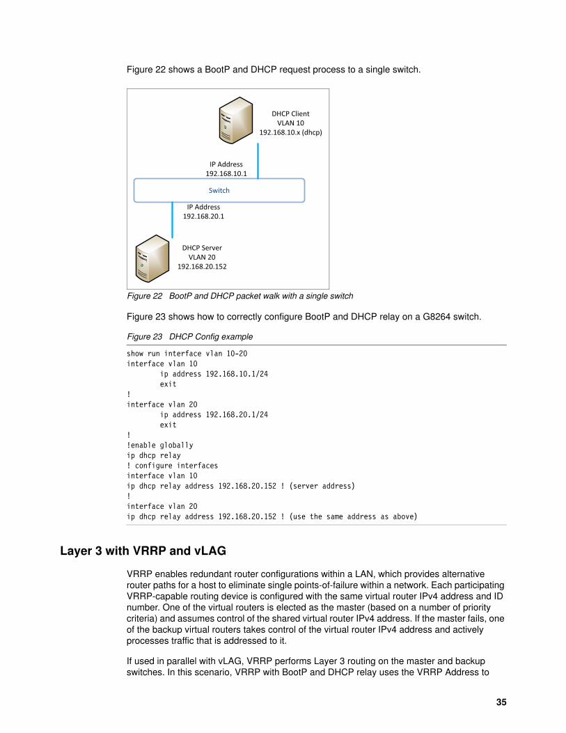
Figure 22 shows a BootP and DHCP request process to a single switch.
Figure 22 BootP and DHCP packet walk with a single switch
Figure 23 shows how to correctly configure BootP and DHCP relay on a G8264 switch.
Figure 23 DHCP Config example
show run interface vlan 10-20interface vlan 10 ip address 192.168.10.1/24 exit!interface vlan 20 ip address 192.168.20.1/24 exit!!enable globallyip dhcp relay! configure interfacesinterface vlan 10ip dhcp relay address 192.168.20.152 ! (server address)!interface vlan 20ip dhcp relay address 192.168.20.152 ! (use the same address as above)
Layer 3 with VRRP and vLAG
VRRP enables redundant router configurations within a LAN, which provides alternative router paths for a host to eliminate single points-of-failure within a network. Each participating VRRP-capable routing device is configured with the same virtual router IPv4 address and ID number. One of the virtual routers is elected as the master (based on a number of priority criteria) and assumes control of the shared virtual router IPv4 address. If the master fails, one of the backup virtual routers takes control of the virtual router IPv4 address and actively processes traffic that is addressed to it.
If used in parallel with vLAG, VRRP performs Layer 3 routing on the master and backup switches. In this scenario, VRRP with BootP and DHCP relay uses the VRRP Address to
Switch
DHCP ServerVLAN 20
192.168.20.152
DHCP ClientVLAN 10
192.168.10.x (dhcp)
IP Address 192.168.20.1
IP Address 192.168.10.1
35

communicate with the Client and Server. Figure 24 shows a BootP and DHCP request process to a single switch.
Figure 24 BootP and DHCP packet walk for a switch that is running VRRP with vLAG
Figure 25 shows how to correctly configure BootP and DHCP relay with VRRP.
Figure 25 DHCP Config example with VRRP configured
Running configuration segments interface vlan 10 ip address 192.168.10.2/24 exit!interface vlan 20 ip address 192.168.20.2/24 exit!!enable globallyip dhcp relay!!configure interfacesinterface vlan 10ip dhcp relay address 192.168.20.152!interface vlan 20ip dhcp relay address ! same address as above interface vlan 10 vrrp 10 address 192.168.10.1 priority 101!interface vlan 20 vrrp 20 address 192.168.20.1 priority 101
Layer 3 ������
DHCP Server�VLAN 20�
192.168.0.152
192.168.0.1VRRP
192.168.0.1Layer 3 Switch
DHCP ClientVLAN 10
192.168.10.x (dhcp)
36 Lenovo Networking Best Practices for CNOS: Layer 2 Design and Configuration

Change history
May 22, 2019
� Minor corrections
April 30, 2019
� Updated to CNOS release 10.x firmware� Updated to current Lenovo networking product portfolio
January 31, 2019:
� Corrections to grammar and readability
Author
Scott Lorditch is a Consulting System Engineer for Lenovo. He performs network architecture assessments and develops designs and proposals for solutions that involve Lenovo Networking products. He also developed several training and lab sessions for technical and sales personnel. Scott joined IBM as part of the acquisition of Blade Network Technologies® and joined Lenovo as part of the System x® acquisition from IBM. Scott spent almost 20 years working on networking in various industries, as a senior network architect, a product manager for managed hosting services, and manager of electronic securities transfer projects. Scott holds a BS degree in Operations Research with a specialization in computer science from Cornell University.
Thanks to the following people for their contributions to this project:
� Philippe Cauche� David Watts
This paper is based on a chapter in the Lenovo Press book, Lenovo Networking Best Practices for Configuration and Installation. Thanks to the authors:
� Scott Irwin � Scott Lorditch � Ted McDaniel � William Nelson � Matt Slavin� Megan Gilge
37

Notices
Lenovo may not offer the products, services, or features discussed in this document in all countries. Consult your local Lenovo representative for information on the products and services currently available in your area. Any reference to a Lenovo product, program, or service is not intended to state or imply that only that Lenovo product, program, or service may be used. Any functionally equivalent product, program, or service that does not infringe any Lenovo intellectual property right may be used instead. However, it is the user's responsibility to evaluate and verify the operation of any other product, program, or service.
Lenovo may have patents or pending patent applications covering subject matter described in this document. The furnishing of this document does not give you any license to these patents. You can send license inquiries, in writing, to:
Lenovo (United States), Inc.1009 Think Place - Building OneMorrisville, NC 27560U.S.A.Attention: Lenovo Director of Licensing
LENOVO PROVIDES THIS PUBLICATION “AS IS” WITHOUT WARRANTY OF ANY KIND, EITHER EXPRESS OR IMPLIED, INCLUDING, BUT NOT LIMITED TO, THE IMPLIED WARRANTIES OF NON-INFRINGEMENT, MERCHANTABILITY OR FITNESS FOR A PARTICULAR PURPOSE. Some jurisdictions do not allow disclaimer of express or implied warranties in certain transactions, therefore, this statement may not apply to you.
This information could include technical inaccuracies or typographical errors. Changes are periodically made to the information herein; these changes will be incorporated in new editions of the publication. Lenovo may make improvements and/or changes in the product(s) and/or the program(s) described in this publication at any time without notice.
The products described in this document are not intended for use in implantation or other life support applications where malfunction may result in injury or death to persons. The information contained in this document does not affect or change Lenovo product specifications or warranties. Nothing in this document shall operate as an express or implied license or indemnity under the intellectual property rights of Lenovo or third parties. All information contained in this document was obtained in specific environments and is presented as an illustration. The result obtained in other operating environments may vary.
Lenovo may use or distribute any of the information you supply in any way it believes appropriate without incurring any obligation to you.
Any references in this publication to non-Lenovo Web sites are provided for convenience only and do not in any manner serve as an endorsement of those Web sites. The materials at those Web sites are not part of the materials for this Lenovo product, and use of those Web sites is at your own risk.
Any performance data contained herein was determined in a controlled environment. Therefore, the result obtained in other operating environments may vary significantly. Some measurements may have been made on development-level systems and there is no guarantee that these measurements will be the same on generally available systems. Furthermore, some measurements may have been estimated through extrapolation. Actual results may vary. Users of this document should verify the applicable data for their specific environment.
© Copyright Lenovo 2019. All rights reserved.Note to U.S. Government Users Restricted Rights -- Use, duplication or disclosure restricted by Global Services Administration (GSA) ADP Schedule Contract 38

This document was created or updated on May 22, 2019.
Send us your comments via the Rate & Provide Feedback form found athttp://lenovopress.com/lp1005
Trademarks
Lenovo, the Lenovo logo, and For Those Who Do are trademarks or registered trademarks of Lenovo in the United States, other countries, or both. These and other Lenovo trademarked terms are marked on their first occurrence in this information with the appropriate symbol (® or ™), indicating US registered or common law trademarks owned by Lenovo at the time this information was published. Such trademarks may also be registered or common law trademarks in other countries. A current list of Lenovo trademarks is available on the Web at http://www.lenovo.com/legal/copytrade.html.
The following terms are trademarks of Lenovo in the United States, other countries, or both:
Blade Network Technologies®Flex System™
Lenovo®RackSwitch™
Lenovo(logo)®System x®
The following terms are trademarks of other companies:
Other company, product, or service names may be trademarks or service marks of others.
39
Related Documents