Arduino and LEGO Projects by Jon Lazar Apress. (c) 2013. Copying Prohibited. Reprinted for RUBEN GARCIA GIMENA, BP [email protected] Reprinted with permission as a subscription benefit of Skillport, http://skillport.books24x7.com/ All rights reserved. Reproduction and/or distribution in whole or in part in electronic,paper or other forms without written permission is prohibited.

Welcome message from author
This document is posted to help you gain knowledge. Please leave a comment to let me know what you think about it! Share it to your friends and learn new things together.
Transcript

Arduino and LEGO Projects
by Jon Lazar Apress. (c) 2013. Copying Prohibited.
Reprinted for RUBEN GARCIA GIMENA, BP
Reprinted with permission as a subscription benefit of Skillport, http://skillport.books24x7.com/
All rights reserved. Reproduction and/or distribution in whole or in part in electronic,paper or other forms without written permission is prohibited.
Chapter 1: LEGO, Arduino, and the Ultimate Machine
Overview
For years LEGO has produced their own computer based system known as Mindstorms. It gave a computer brain to the plastic LEGO bricks that had been around for decades. While Mindstorms has advanced in the 15 years since it was introduced, it was still limited based on the size of the LEGO Intelligent Brick and the available sensors and motors. An alternative to using the LEGO Mindstorms is the Arduino microprocessor, a small computer that can make use of any electrical components with some programming.
Introducing the Arduino
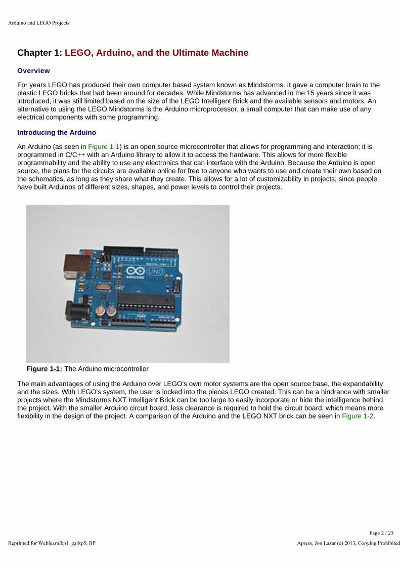
An Arduino (as seen in Figure 1-1) is an open source microcontroller that allows for programming and interaction; it is programmed in C/C++ with an Arduino library to allow it to access the hardware. This allows for more flexible programmability and the ability to use any electronics that can interface with the Arduino. Because the Arduino is open source, the plans for the circuits are available online for free to anyone who wants to use and create their own based on the schematics, as long as they share what they create. This allows for a lot of customizability in projects, since people have built Arduinos of different sizes, shapes, and power levels to control their projects.
Figure 1-1: The Arduino microcontroller
The main advantages of using the Arduino over LEGO's own motor systems are the open source base, the expandability, and the sizes. With LEGO's system, the user is locked into the pieces LEGO created. This can be a hindrance with smaller projects where the Mindstorms NXT Intelligent Brick can be too large to easily incorporate or hide the intelligence behind the project. With the smaller Arduino circuit board, less clearance is required to hold the circuit board, which means more flexibility in the design of the project. A comparison of the Arduino and the LEGO NXT brick can be seen in Figure 1-2.
Arduino and LEGO Projects
Reprinted for Weblearn/bp1_garkp5, BP Apress, Jon Lazar (c) 2013, Copying Prohibited
Page 2 / 23
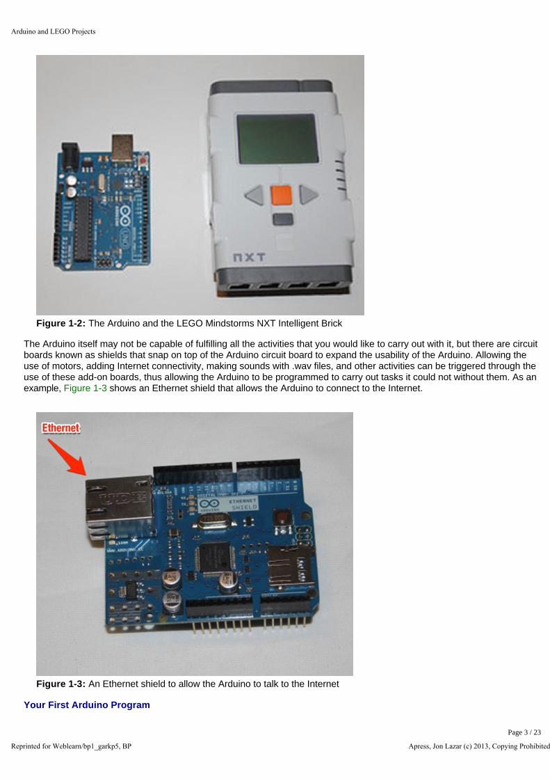
Figure 1-2: The Arduino and the LEGO Mindstorms NXT Intelligent Brick
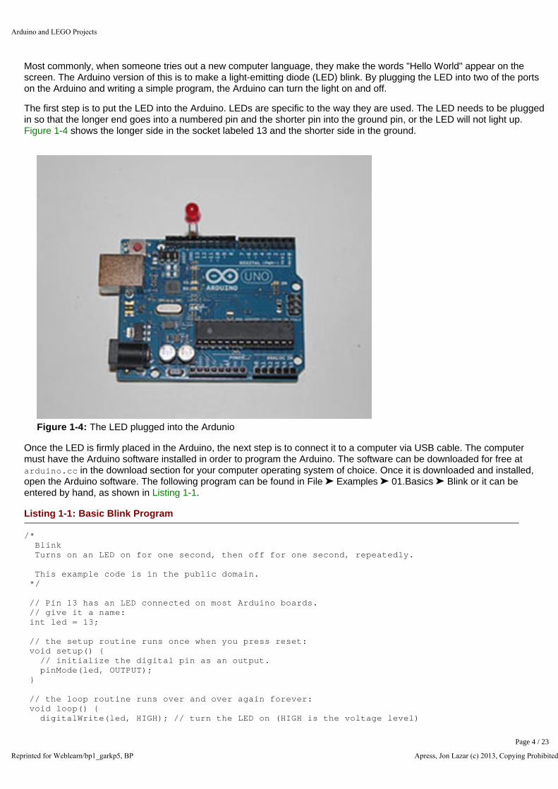
The Arduino itself may not be capable of fulfilling all the activities that you would like to carry out with it, but there are circuit boards known as shields that snap on top of the Arduino circuit board to expand the usability of the Arduino. Allowing the use of motors, adding Internet connectivity, making sounds with .wav files, and other activities can be triggered through the use of these add-on boards, thus allowing the Arduino to be programmed to carry out tasks it could not without them. As an example, Figure 1-3 shows an Ethernet shield that allows the Arduino to connect to the Internet.
Figure 1-3: An Ethernet shield to allow the Arduino to talk to the Internet
Your First Arduino Program
Arduino and LEGO Projects
Reprinted for Weblearn/bp1_garkp5, BP Apress, Jon Lazar (c) 2013, Copying Prohibited
Page 3 / 23
Most commonly, when someone tries out a new computer language, they make the words "Hello World" appear on the screen. The Arduino version of this is to make a light-emitting diode (LED) blink. By plugging the LED into two of the ports on the Arduino and writing a simple program, the Arduino can turn the light on and off.
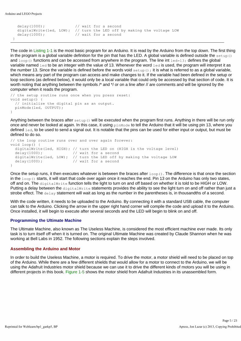
The first step is to put the LED into the Arduino. LEDs are specific to the way they are used. The LED needs to be plugged in so that the longer end goes into a numbered pin and the shorter pin into the ground pin, or the LED will not light up. Figure 1-4 shows the longer side in the socket labeled 13 and the shorter side in the ground.
Figure 1-4: The LED plugged into the Ardunio
Once the LED is firmly placed in the Arduino, the next step is to connect it to a computer via USB cable. The computer must have the Arduino software installed in order to program the Arduino. The software can be downloaded for free at arduino.cc in the download section for your computer operating system of choice. Once it is downloaded and installed, open the Arduino software. The following program can be found in File Examples 01.Basics Blink or it can be entered by hand, as shown in Listing 1-1.
Listing 1-1: Basic Blink Program
/* Blink Turns on an LED on for one second, then off for one second, repeatedly. This example code is in the public domain. */ // Pin 13 has an LED connected on most Arduino boards. // give it a name: int led = 13; // the setup routine runs once when you press reset: void setup() { // initialize the digital pin as an output. pinMode(led, OUTPUT); } // the loop routine runs over and over again forever: void loop() { digitalWrite(led, HIGH); // turn the LED on (HIGH is the voltage level)
Arduino and LEGO Projects
Reprinted for Weblearn/bp1_garkp5, BP Apress, Jon Lazar (c) 2013, Copying Prohibited
Page 4 / 23
delay(1000); // wait for a second digitalWrite(led, LOW); // turn the LED off by making the voltage LOW delay(1000); // wait for a second }
The code in Listing 1-1 is the most basic program for an Arduino. It is read by the Arduino from the top down. The first thing in the program is a global variable definition for the pin that has the LED. A global variable is defined outside the setup() and loop() functions and can be accessed from anywhere in the program. The line int led=13; defines the global variable named led to be an integer with the value of 13. Whenever the word led is used, the program will interpret it as the number 13. Since the variable is defined before the words void setup(); it is what is referred to as a global variable, which means any part of the program can access and make changes to it. If the variable had been defined in the setup or loop sections (as defined below), it would only be a local variable that could only be accessed by that section of code. It is worth noting that anything between the symbols /* and */ or on a line after // are comments and will be ignored by the computer when it reads the program.
// the setup routine runs once when you press reset: void setup() { // initialize the digital pin as an output. pinMode(led, OUTPUT); }
Anything between the braces after setup() will be executed when the program first runs. Anything in there will be run only once and never be looked at again. In this case, it using pinMode to tell the Arduino that it will be using pin 13, where you defined led, to be used to send a signal out. It is notable that the pins can be used for either input or output, but must be defined to do so.
// the loop routine runs over and over again forever: void loop() { digitalWrite(led, HIGH); // turn the LED on (HIGH is the voltage level) delay(1000); // wait for a second digitalWrite(led, LOW); // turn the LED off by making the voltage LOW delay(1000); // wait for a second }
Once the setup runs, it then executes whatever is between the braces after loop(). The difference is that once the section in the loop() starts, it will start that code over again once it reaches the end. Pin 13 on the Arduino has only two states, off and on. The digitalWrite function tells the light to turn on and off based on whether it is told to be HIGH or LOW. Putting a delay between the digitalWrite statements provides the ability to see the light turn on and off rather than just a strobe effect. The delay statement will wait as long as the number in the parentheses is, in thousandths of a second.
With the code written, it needs to be uploaded to the Arduino. By connecting it with a standard USB cable, the computer can talk to the Arduino. Clicking the arrow in the upper right hand corner will compile the code and upload it to the Arduino. Once installed, it will begin to execute after several seconds and the LED will begin to blink on and off.
Programming the Ultimate Machine
The Ultimate Machine, also known as The Useless Machine, is considered the most efficient machine ever made. Its only task is to turn itself off when it is turned on. The original Ultimate Machine was created by Claude Shannon when he was working at Bell Labs in 1952. The following sections explain the steps involved.
Assembling the Arduino and Motor
In order to build the Useless Machine, a motor is required. To drive the motor, a motor shield will need to be placed on top of the Arduino. While there are a few different shields that would allow for a motor to connect to the Arduino, we will be using the Adafruit Industries motor shield because we can use it to drive the different kinds of motors you will be using in different projects in this book. Figure 1-5 shows the motor shield from Adafruit Industries in its unassembled form.
Arduino and LEGO Projects
Reprinted for Weblearn/bp1_garkp5, BP Apress, Jon Lazar (c) 2013, Copying Prohibited
Page 5 / 23
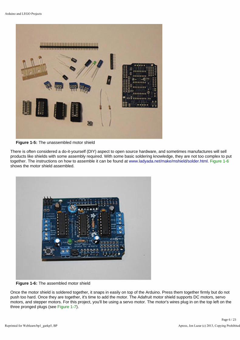
Figure 1-5: The unassembled motor shield
There is often considered a do-it-yourself (DIY) aspect to open source hardware, and sometimes manufactures will sell products like shields with some assembly required. With some basic soldering knowledge, they are not too complex to put together. The instructions on how to assemble it can be found at www.ladyada.net/make/mshield/solder.html. Figure 1-6 shows the motor shield assembled.
Figure 1-6: The assembled motor shield
Once the motor shield is soldered together, it snaps in easily on top of the Arduino. Press them together firmly but do not push too hard. Once they are together, it's time to add the motor. The Adafruit motor shield supports DC motors, servo motors, and stepper motors. For this project, you'll be using a servo motor. The motor's wires plug in on the top left on the three pronged plugs (see Figure 1-7).
Arduino and LEGO Projects
Reprinted for Weblearn/bp1_garkp5, BP Apress, Jon Lazar (c) 2013, Copying Prohibited
Page 6 / 23

Figure 1-7: The motor shield on top of the Arduino with the servo motor attached
In the Blink example, you power the Arduino with the USB cable to the computer. Since this project will eventually be independent of the computer, a battery pack or wall adapter will be required to power the project. If the wall adapter is used, it plugs directly into the Arduino, and the LEGO casing will require a hole the width of one LEGO stud. Some motors will require a second power source due to the power consumption of the motors, but for this project, the single power source will be enough for the Arduino and servo motor.
With the Arduino and motor shield set up, there is one last piece of hardware to connect before programming your project. The Ultimate Machine moves into action when a person flips a switch to turn the machine on. Since the machine needs to be switched on, you need to add a switch. You will take a switch (the one in Figure 1-8 is from Radio Shack), solder wires to it, and plug it into one of the digital ports on top of the motor shield so the machine will know when to activate. Since you are using the shield rather than the Arduino itself, the wires will need to be soldered in place to make a secure connection. One end will be soldered into the numbered pin, the other end will be soldered into one of the ground ports, as shown in Figure 1-9.
Arduino and LEGO Projects
Reprinted for Weblearn/bp1_garkp5, BP Apress, Jon Lazar (c) 2013, Copying Prohibited
Page 7 / 23

Figure 1-8: The switch added to the Arduino, motor shield, and motor
Figure 1-9: Diagram of the motor and switch connection, as connected without the motor shield
Programming the Arduino
Once the hardware is completed, it is time to build the software. The program to run the motor is has a similar layout to the program you wrote for the Blink program, but is a little more advanced. The first thing you need to do is include the library for the motor shield. The library includes code that has already been written to drive the motor shield, so you don't have to start from scratch to address the hardware yourself. To install the library, go to www.ladyada.net/make/mshield/use.html and follow the instructions to download and install the motor shield library. Once it is installed and the Arduino software is restarted, copy the code in Listing 1-2.
Arduino and LEGO Projects
Reprinted for Weblearn/bp1_garkp5, BP Apress, Jon Lazar (c) 2013, Copying Prohibited
Page 8 / 23

Listing 1-2: The Ultimate Machine Code
#include <Servo.h> // DC hobby servo Servo servo1; // Switch connected to digital pin 2 int SwitchPin = 2; void setup() { // turn on servo servo1.attach(9); // sets the digital pin 2 as input // and enables pullup resistor pinMode(SwitchPin, INPUT_PULLUP); } void loop() { // read the input pin int val = digitalRead(SwitchPin); // test if switch has been triggered if (val == LOW) { servo1.write(115); delay(250); servo1.write(0); } delay(100); }
Again, the code is broken into three parts. The first part contains the global variable definitions. Here, you set variables that you want accessible throughout the code. The two include statements at the top of the code include the libraries to interact with the motor. The #include <AFMotor.h> tells the Arduino code that you are going to be using the motor library and the #include <Servo.h> loads the necessary code to use a servo motor. After including them both, you can initialize the servo motor with Servo servo1, which defines the motor and gives it the name servo, which is how you will refer to it as in the rest of the code. Int SwitchPin = 2 sets a number value to SwitchPin, which will be the pin that one end of the switch was soldered into.
In the setup() section, you set up the motor and switch so that you can use them in the loop(). Servo1.attach(9) turns on the servo and tells the code that the servo can be accessed through digital pin 9. pinMode(SwitchPin, INPUT_PULLUP) sets the pin to an input mode to receive digital signals from an external device, in this case a switch. It will be on the port you previously defined in the int statement, so when the switch is active on that port, the code will be able to react.
The third and final part of the code is the loop(). The first thing you need to do is check the status of the switch, so int val = digitalRead(SwitchPin) will put a value in the val variable based on whether the switch is open or closed. The if statement checks the status of the val variable, and if it is LOW, it executes the code within the braces of the if statement. The code will tell the servo motor to move forward 115 degrees with the servo1.write(115) command, then waits 250 milliseconds in the delay(250) command before returning back into the box with servo1.write(0). Once the motor is reset to its initial position, it continues the loop and waits for the switch to be flipped again to turn itself off again.
A typical hobby servo motor can only move 180 degrees, but your motor does not need to move that far to trigger the switch. When building the project, if the motor doesn't move far enough or if it moves too far, adjusting the 115 in the servo1.write() command will adjust how far the motor moves.
Building the Ultimate Machine
Once the Arduino, motor, and switch are set, it's time to build the box to hold it all. The first principle of LEGO building is to build sturdy. Just like in real life, you don't just stack bricks on top of each other, otherwise your buildings would not be sturdy. As seen in Figure 1-10, you stagger your LEGO bricks and cover the seams with bricks, alternating the layout of the bricks in what you are building. This holds the building together and creates a more sturdy framework. It's this sturdiness that allows you to build projects that hold together tightly without needing any glue or extra adhesives for
Arduino and LEGO Projects
Reprinted for Weblearn/bp1_garkp5, BP Apress, Jon Lazar (c) 2013, Copying Prohibited
Page 9 / 23
strength.
Figure 1-10: On the left are LEGO bricks stacked one atop the other, while on the right are bricks in a staggered formation. Notice how the bricks cover the seams above and below them, holding the bricks together
The complete parts list for this project can be found in the appendix.
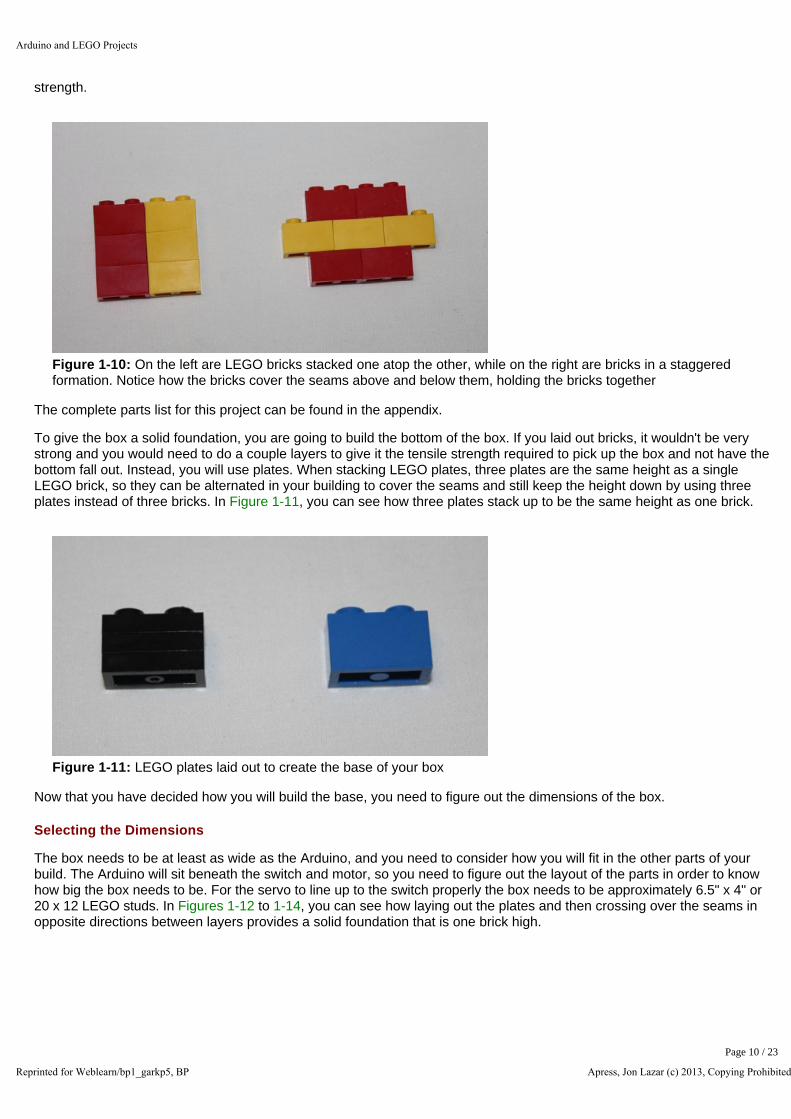
To give the box a solid foundation, you are going to build the bottom of the box. If you laid out bricks, it wouldn't be very strong and you would need to do a couple layers to give it the tensile strength required to pick up the box and not have the bottom fall out. Instead, you will use plates. When stacking LEGO plates, three plates are the same height as a single LEGO brick, so they can be alternated in your building to cover the seams and still keep the height down by using three plates instead of three bricks. In Figure 1-11, you can see how three plates stack up to be the same height as one brick.
Figure 1-11: LEGO plates laid out to create the base of your box
Now that you have decided how you will build the base, you need to figure out the dimensions of the box.
Selecting the Dimensions
The box needs to be at least as wide as the Arduino, and you need to consider how you will fit in the other parts of your build. The Arduino will sit beneath the switch and motor, so you need to figure out the layout of the parts in order to know how big the box needs to be. For the servo to line up to the switch properly the box needs to be approximately 6.5" x 4" or 20 x 12 LEGO studs. In Figures 1-12 to 1-14, you can see how laying out the plates and then crossing over the seams in opposite directions between layers provides a solid foundation that is one brick high.
Arduino and LEGO Projects
Reprinted for Weblearn/bp1_garkp5, BP Apress, Jon Lazar (c) 2013, Copying Prohibited
Page 10 / 23

Figure 1-12: LEGO plates are laid out to create the base of the box
Figure 1-13: The second layer of LEGO plates covers the first layer, but criss-crosses the seams of the first layer to secure them
Arduino and LEGO Projects
Reprinted for Weblearn/bp1_garkp5, BP Apress, Jon Lazar (c) 2013, Copying Prohibited
Page 11 / 23
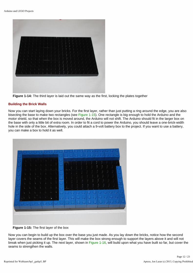
Figure 1-14: The third layer is laid out the same way as the first, locking the plates together
Building the Brick Walls
Now you can start laying down your bricks. For the first layer, rather than just putting a ring around the edge, you are also bisecting the base to make two rectangles (see Figure 1-15). One rectangle is big enough to hold the Arduino and the motor shield, so that when the box is moved around, the Arduino will not shift. The Arduino should fit in the larger box on the base with only a little bit of extra room. In order to fit a cord to power the Arduino, you should leave a one-brick-width hole in the side of the box. Alternatively, you could attach a 9-volt battery box to the project. If you want to use a battery, you can make a box to hold it as well.
Figure 1-15: The first layer of the box
Now you can begin to build up the box over the base you just made. As you lay down the bricks, notice how the second layer covers the seams of the first layer. This will make the box strong enough to support the layers above it and will not break when just picking it up. The next layer, shown in Figure 1-16, will build upon what you have built so far, but cover the seams to strengthen the walls.
Arduino and LEGO Projects
Reprinted for Weblearn/bp1_garkp5, BP Apress, Jon Lazar (c) 2013, Copying Prohibited
Page 12 / 23
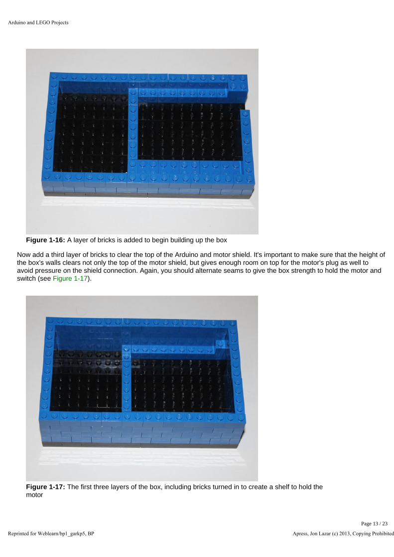
Figure 1-16: A layer of bricks is added to begin building up the box
Now add a third layer of bricks to clear the top of the Arduino and motor shield. It's important to make sure that the height of the box's walls clears not only the top of the motor shield, but gives enough room on top for the motor's plug as well to avoid pressure on the shield connection. Again, you should alternate seams to give the box strength to hold the motor and switch (see Figure 1-17).
Figure 1-17: The first three layers of the box, including bricks turned in to create a shelf to hold the motor
Arduino and LEGO Projects
Reprinted for Weblearn/bp1_garkp5, BP Apress, Jon Lazar (c) 2013, Copying Prohibited
Page 13 / 23

Adding The Arduino
With the base of the box completed, it's time to start adding the electronics. The first step is to add in the Arduino in the bottom of the box, as seen in Figure 1-18.
Figure 1-18: The Arduino is easily seated into the section you made for it
You can now place a base of plates on top of the box to hold the motor and the switch. You can create a small box to hold it in place. Make sure the small box holds the switch tight, since the motor will be pushing on the switch with a firm amount of force. If the small box breaks or pushes the bricks apart, reinforce the top with plates to give them a firmer grip on the bricks. It is also important to give the wires on the bottom of the switch a way to be fed out of the box; either leave an opening in the first level of the small box or use a LEGO Technic brick and feed the wires out through the hole in the brick, as seen in Figure 1-19.
Arduino and LEGO Projects
Reprinted for Weblearn/bp1_garkp5, BP Apress, Jon Lazar (c) 2013, Copying Prohibited
Page 14 / 23

Figure 1-19: The small LEGO box to hold the toggle switch with the wires fed through a Technic brick
A platform is then added to hold the toggle switch and servo motor. The switch and motor need to be lined up when the machine is turned on. The motor is lined up with LEGO bricks to keep it in place while you build the rest of the box. It will be made more secure as the walls are built higher, which can be seen in Figure 1-20.
Figure 1-20: The servo motor and toggle switch are laid out on top of stacked LEGO plates and lined up using LEGO bricks
Adding LEGO Arms and a Switch
With the motor and switch in place, the LEGO arms for the motor and switch need to be set up, since that is what will be seen from outside the box. In Figures 1-21 through 1-25, a LEGO Technic beam is secured with a wire to a disc that came with the servo motor, then LEGO Technic beams are added to the top of it, plus a Technic pin with two Technic angle connectors on the ends to give it a wider reach when it comes up to hit the switch. Once that is done, Technic axle joiners are connected by 2M pins to create a pole that the Technic beams can hit with the machine is on, which will just slide over the top of the toggle switch.
Arduino and LEGO Projects
Reprinted for Weblearn/bp1_garkp5, BP Apress, Jon Lazar (c) 2013, Copying Prohibited
Page 15 / 23

Figure 1-21: A curved Technic beam is wired to the servo motor's disc
Figure 1-22: Angled Technic beams are added to the end of the secured Technic beam, and a 5M pin and two angle connectors hold it in place
Arduino and LEGO Projects
Reprinted for Weblearn/bp1_garkp5, BP Apress, Jon Lazar (c) 2013, Copying Prohibited
Page 16 / 23

Figure 1-23: Four axle joiners and three 2M pins extend the switch
Figure 1-24: The finished attachment for the switch
Arduino and LEGO Projects
Reprinted for Weblearn/bp1_garkp5, BP Apress, Jon Lazar (c) 2013, Copying Prohibited
Page 17 / 23
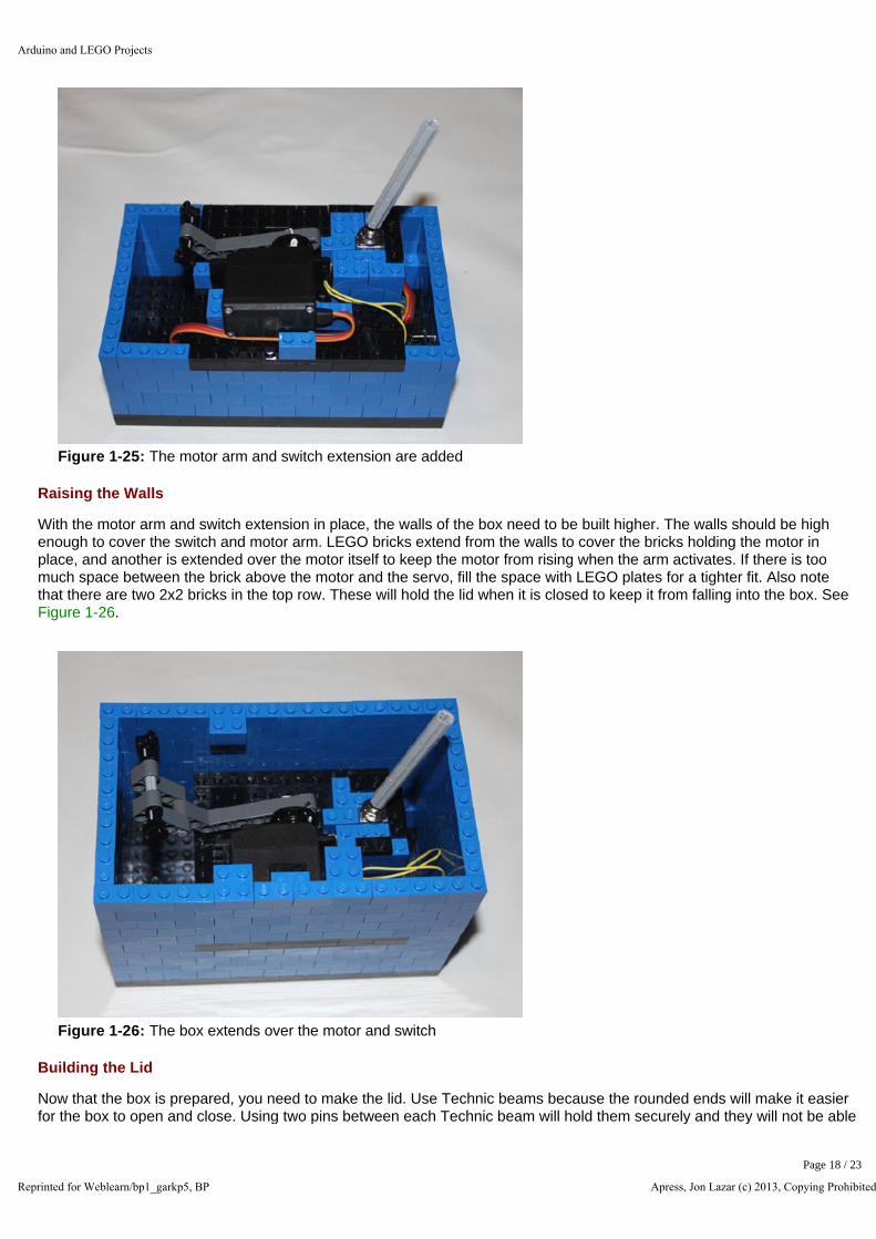
Figure 1-25: The motor arm and switch extension are added
Raising the Walls
With the motor arm and switch extension in place, the walls of the box need to be built higher. The walls should be high enough to cover the switch and motor arm. LEGO bricks extend from the walls to cover the bricks holding the motor in place, and another is extended over the motor itself to keep the motor from rising when the arm activates. If there is too much space between the brick above the motor and the servo, fill the space with LEGO plates for a tighter fit. Also note that there are two 2x2 bricks in the top row. These will hold the lid when it is closed to keep it from falling into the box. See Figure 1-26.
Figure 1-26: The box extends over the motor and switch
Building the Lid
Now that the box is prepared, you need to make the lid. Use Technic beams because the rounded ends will make it easier for the box to open and close. Using two pins between each Technic beam will hold them securely and they will not be able
Arduino and LEGO Projects
Reprinted for Weblearn/bp1_garkp5, BP Apress, Jon Lazar (c) 2013, Copying Prohibited
Page 18 / 23

to move. Figures 1-27 and 1-28 show the parts and assembly of the lid.
Figure 1-27: 11M Technic beams and black friction Technic beams to hold them together. Two pins should connect between each beam to hold them securely
Figure 1-28: The Technic beams connected. There are 2 pins between each beam
Two Technic bricks with holes in the middle will go on the ends with gray pins to hinge the joint. Use the gray pins there because they are frictionless and allow more movement than the black friction pins. Once the lid is added to the box, a layer of bricks is added around the lid. See Figures 1-29 through 1-32.
Arduino and LEGO Projects
Reprinted for Weblearn/bp1_garkp5, BP Apress, Jon Lazar (c) 2013, Copying Prohibited
Page 19 / 23
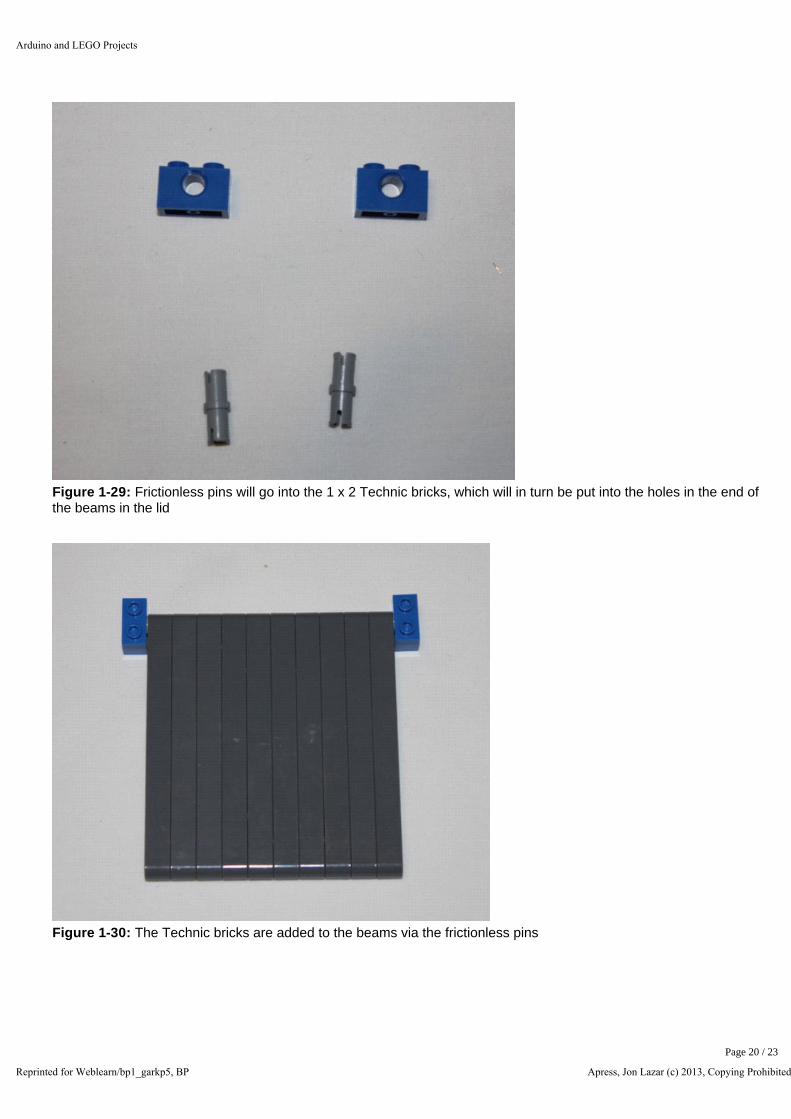
Figure 1-29: Frictionless pins will go into the 1 x 2 Technic bricks, which will in turn be put into the holes in the end of the beams in the lid
Figure 1-30: The Technic bricks are added to the beams via the frictionless pins
Arduino and LEGO Projects
Reprinted for Weblearn/bp1_garkp5, BP Apress, Jon Lazar (c) 2013, Copying Prohibited
Page 20 / 23
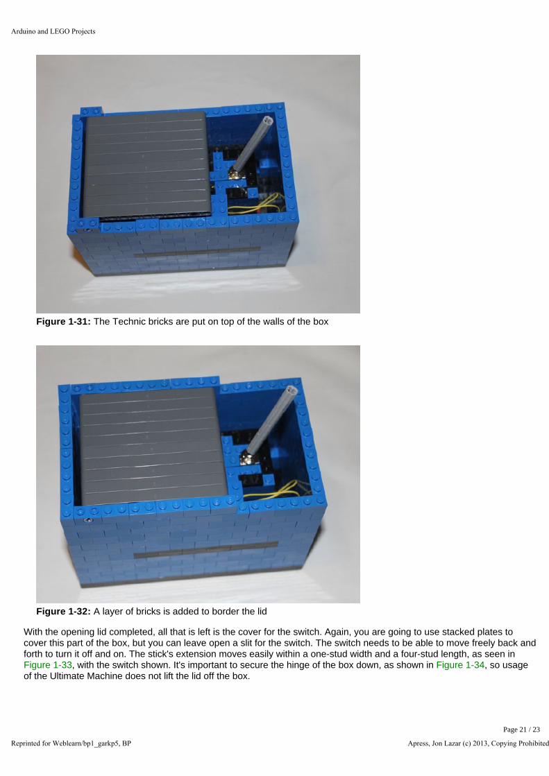
Figure 1-31: The Technic bricks are put on top of the walls of the box
Figure 1-32: A layer of bricks is added to border the lid
With the opening lid completed, all that is left is the cover for the switch. Again, you are going to use stacked plates to cover this part of the box, but you can leave open a slit for the switch. The switch needs to be able to move freely back and forth to turn it off and on. The stick's extension moves easily within a one-stud width and a four-stud length, as seen in Figure 1-33, with the switch shown. It's important to secure the hinge of the box down, as shown in Figure 1-34, so usage of the Ultimate Machine does not lift the lid off the box.
Arduino and LEGO Projects
Reprinted for Weblearn/bp1_garkp5, BP Apress, Jon Lazar (c) 2013, Copying Prohibited
Page 21 / 23

Figure 1-33: The completed box, ready to turn itself off and on
Figure 1-34: The activated Ultimate Machine
With the switch covered, you have completed your first project. By flipping the switch towards the lid, the machine will be activated and the motor arm will come to life, only to push the switch away from itself and return to its dormant state until it is activated again.
Summary
You just completed an introduction to LEGO building and the Arduino. You learned the basic techniques for using an Arduino, starting from the most basic of programs, making an LED blink, to a more complex one using Arduino shields. You also learned the most basic LEGO building principle of build strong by using a strong base and alternating the bricks to create walls that can support your building. Combining the two gives you the ability to make more interesting projects and
Arduino and LEGO Projects
Reprinted for Weblearn/bp1_garkp5, BP Apress, Jon Lazar (c) 2013, Copying Prohibited
Page 22 / 23

give them different levels of activity and interactivity, as you will explore in the following chapters.
Arduino and LEGO Projects
Reprinted for Weblearn/bp1_garkp5, BP Apress, Jon Lazar (c) 2013, Copying Prohibited
Page 23 / 23
Related Documents


