Ledex ® Rotary Solenoids Maximum Duty Cycle 100% 50% 25% 10% 5% Maximum ON Time (sec) ∞ 100 36 8 2.8 when pulsed continuously 1 Maximum ON Time (sec) ∞ 162 44 9 3.2 for single pulse 2 Watts (@ 20°C) 10 20 40 100 200 Ampere Turns (@ 20°C) 550 785 1,100 1,740 2,464 Coil Data awg Resistance # VDC VDC VDC VDC VDC

Welcome message from author
This document is posted to help you gain knowledge. Please leave a comment to let me know what you think about it! Share it to your friends and learn new things together.
Transcript
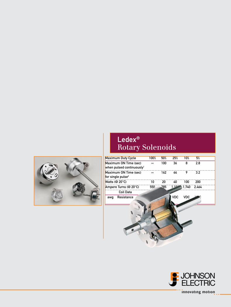
Ledex®
Rotary SolenoidsMaximum Duty Cycle 100% 50% 25% 10% 5%Maximum ON Time (sec) ∞ 100 36 8 2.8 when pulsed continuously1
Maximum ON Time (sec) ∞ 162 44 9 3.2 for single pulse2
Watts (@ 20°C) 10 20 40 100 200Ampere Turns (@ 20°C) 550 785 1,100 1,740 2,464 Coil Data awg Resistance # VDC VDC VDC VDC VDC
Ledex® Solenoids www.ledex.comD2
ROT
ARY
Sol
enoi
ds
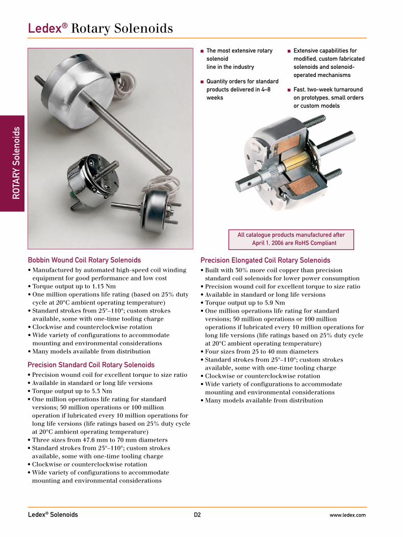
Precision Elongated Coil Rotary Solenoids• Built with 30% more coil copper than precision
standard coil solenoids for lower power consumption• Precision wound coil for excellent torque to size ratio• Available in standard or long life versions• Torque output up to 5.9 Nm• One million operations life rating for standard
versions; 50 million operations or 100 million operations if lubricated every 10 million operations for long life versions (life ratings based on 25% duty cycle at 20°C ambient operating temperature)
• Four sizes from 25 to 40 mm diameters• Standard strokes from 25°–110°; custom strokes
available, some with one-time tooling charge• Clockwise or counterclockwise rotation• Wide variety of configurations to accommodate
mounting and environmental considerations• Many models available from distribution
Precision Standard Coil Rotary Solenoids• Precision wound coil for excellent torque to size ratio• Available in standard or long life versions• Torque output up to 5.3 Nm• One million operations life rating for standard
versions; 50 million operations or 100 million operation if lubricated every 10 million operations for long life versions (life ratings based on 25% duty cycle at 20°C ambient operating temperature)
• Three sizes from 47.6 mm to 70 mm diameters• Standard strokes from 25°–110°; custom strokes
available, some with one-time tooling charge• Clockwise or counterclockwise rotation• Wide variety of configurations to accommodate
mounting and environmental considerations
■ The most extensive rotary solenoid line in the industry
■ Quantity orders for standard products delivered in 4–8 weeks
Bobbin Wound Coil Rotary Solenoids• Manufactured by automated high-speed coil winding
equipment for good performance and low cost• Torque output up to 1.13 Nm• One million operations life rating (based on 25% duty
cycle at 20°C ambient operating temperature)• Standard strokes from 25°–110°; custom strokes
available, some with one-time tooling charge• Clockwise and counterclockwise rotation• Wide variety of configurations to accommodate
mounting and environmental considerations• Many models available from distribution
■ Extensive capabilities for modified, custom fabricated solenoids and solenoid-operated mechanisms
■ Fast, two-week turnaround on prototypes, small orders or custom models
Ledex® Rotary Solenoids
All catalogue products manufactured after April 1, 2006 are RoHS Compliant
Ledex® Solenoids www.ledex.comD3
ROTA
RY Solenoids
Modified and Custom-Designed Rotary SolenoidsLedex offers comprehensive design and manufacturing
resources to develop application specific rotary solenoids to meet your exact performance and unit cost objectives. Even though we offer thousands of standard rotary solenoid models, almost 80% of the product we build is specifically tailored to our customers’ needs. So if you don’t find exactly what you’re looking for, please call us to discuss your requirements. Here are a few simple design options which we frequently encounter for rotary solenoid applications:• Special shafts• Mounting studs threaded to customer specification • Slots, flats, or holes in shafts for machine linkage• Double return springs for critical safety redundancy• Armature covers
Design Principles
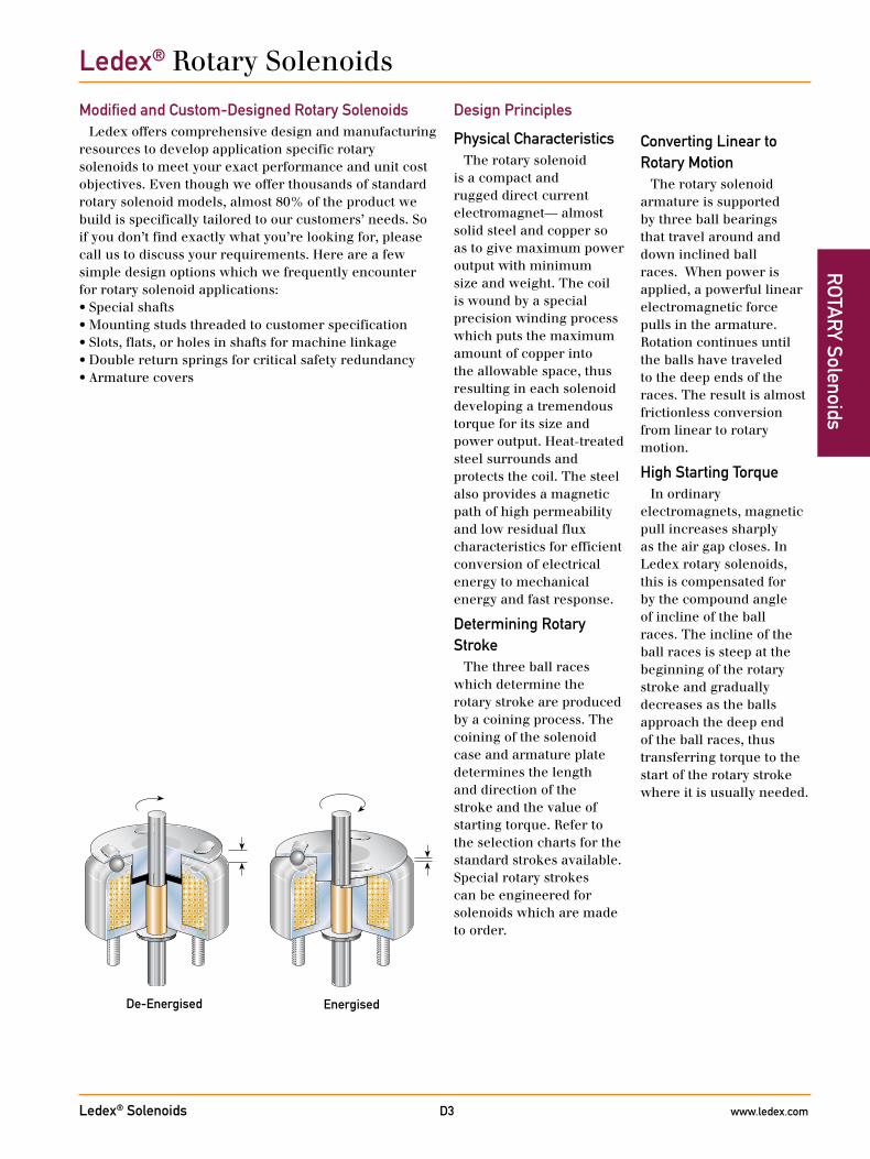
Physical CharacteristicsThe rotary solenoid
is a compact and rugged direct current electromagnet— almost solid steel and copper so as to give maximum power output with minimum size and weight. The coil is wound by a special precision winding process which puts the maximum amount of copper into the allowable space, thus resulting in each solenoid developing a tremendous torque for its size and power output. Heat-treated steel surrounds and protects the coil. The steel also provides a magnetic path of high permeability and low residual flux characteristics for efficient conversion of electrical energy to mechanical energy and fast response.
Determining Rotary Stroke
The three ball races which determine the rotary stroke are produced by a coining process. The coining of the solenoid case and armature plate determines the length and direction of the stroke and the value of starting torque. Refer to the selection charts for the standard strokes available. Special rotary strokes can be engineered for solenoids which are made to order.
Converting Linear to Rotary Motion
The rotary solenoid armature is supported by three ball bearings that travel around and down inclined ball races. When power is applied, a powerful linear electromagnetic force pulls in the armature. Rotation continues until the balls have traveled to the deep ends of the races. The result is almost frictionless conversion from linear to rotary motion.
High Starting TorqueIn ordinary
electromagnets, magnetic pull increases sharply as the air gap closes. In Ledex rotary solenoids, this is compensated for by the compound angle of incline of the ball races. The incline of the ball races is steep at the beginning of the rotary stroke and gradually decreases as the balls approach the deep end of the ball races, thus transferring torque to the start of the rotary stroke where it is usually needed.
De-Energised Energised
Ledex® Rotary Solenoids
Ledex® Solenoids www.ledex.comD4
ROT
ARY
Sol
enoi
dsLedex® Rotary Solenoids Design Considerations
Snap-Acting EngagementRotary solenoids have
fast acting engagement. If a controlled speed is required in a rotary stroke application, consider Ledex BTA rotary actuators.
Unobstructed Axial Stroke
Axial stroke is the linear distance that the armature travels to the centre of the coil as the solenoid is energised and the three bearing balls travel to the lower ends of the races.
The application should allow clearance for axial stroke, which is rarely a problem due to the relatively small magnitude of travel. Axial stroke is listed for each solenoid size and rotary stroke on the appropriate specification pages.
Solenoids without axial stroke, such as our BTA, can be tailored to your application if longitudinal movement must be avoided.
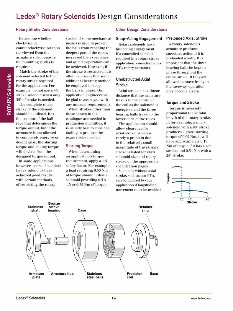
Armature hub
Stainlessshaft
Bronzesleevebearing Case
Retainerring
Stainlesssteel balls
Precisioncoil
BaseArmatureplate
Other Design Considerations
Stroke
To
rqu
e
25° 45° 90°
Determine whether clockwise or counterclockwise rotation (as viewed from the armature side, opposite the mounting studs) is required.
Match the stroke of the solenoid selected to the rotary stroke required for the application. For example: do not use a 45° stroke solenoid when only 35° of stroke is needed.
The complete rotary stroke of the solenoid should be utilised. It is the contour of the ball race that determines the torque output, but if the armature is not allowed to completely energise or de-energise, the starting torque and ending torque will deviate from the designed torque output.
In some applications, however, users of standard Ledex solenoids have achieved good results with certain methods of restricting the rotary
stroke. If some mechanical means is used to prevent the balls from reaching the deepest part of the races, increased life expectancy and quieter operation can be achieved. However, if the stroke is restricted, it is often necessary that some additional bearing method be employed to keep the balls in phase. Our application engineers will be glad to assist you with any unusual requirements.
When strokes other than those shown in this catalogue are needed in production quantities, it is usually best to consider tooling to produce the exact stroke needed.
Starting TorqueWhen determining
an application’s torque requirement, apply a 1.5 safety factor. For example: a load requiring 0.50 Nm of torque should utilise a solenoid providing 0.5 x 1.5 or 0.75 Nm of torque.
Preloaded Axial StrokeA rotary solenoid’s
armature produces smoother action if it is preloaded axially. It is important that the three bearing balls be kept in phase throughout the entire stroke. If they are allowed to move freely in the raceway, operation may become erratic.
Torque and StrokeTorque is inversely
proportional to the total length of the rotary stroke. If, for example, a rotary solenoid with a 90° stroke produces a gross starting torque of 0.09 Nm, it will have approximately 0.19 Nm of torque if it has a 45° stroke, and 0.34 Nm with a 25° stroke.
Rotary Stroke Considerations
Ledex® Solenoids www.ledex.comD5
ROTA
RY Solenoids
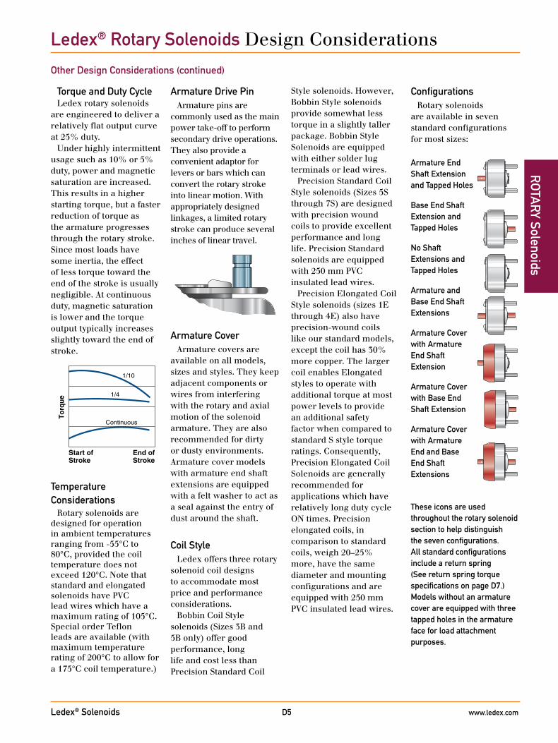
Torque and Duty CycleLedex rotary solenoids
are engineered to deliver a relatively flat output curve at 25% duty.
Under highly intermittent usage such as 10% or 5% duty, power and magnetic saturation are increased. This results in a higher starting torque, but a faster reduction of torque as the armature progresses through the rotary stroke. Since most loads have some inertia, the effect of less torque toward the end of the stroke is usually negligible. At continuous duty, magnetic saturation is lower and the torque output typically increases slightly toward the end of stroke.
Temperature Considerations
Rotary solenoids are designed for operation in ambient temperatures ranging from -55°C to 80°C, provided the coil temperature does not exceed 120°C. Note that standard and elongated solenoids have PVC lead wires which have a maximum rating of 105°C. Special order Teflon leads are available (with maximum temperature rating of 200°C to allow for a 175°C coil temperature.)
Start ofStroke
End ofStroke
1/10
1/4
Continuous
To
rqu
e
Armature Drive PinArmature pins are
commonly used as the main power take-off to perform secondary drive operations. They also provide a convenient adaptor for levers or bars which can convert the rotary stroke into linear motion. With appropriately designed linkages, a limited rotary stroke can produce several inches of linear travel.
Armature CoverArmature covers are
available on all models, sizes and styles. They keep adjacent components or wires from interfering with the rotary and axial motion of the solenoid armature. They are also recommended for dirty or dusty environments. Armature cover models with armature end shaft extensions are equipped with a felt washer to act as a seal against the entry of dust around the shaft.
Coil StyleLedex offers three rotary
solenoid coil designs to accommodate most price and performance considerations.
Bobbin Coil Style solenoids (Sizes 3B and 5B only) offer good performance, long life and cost less than Precision Standard Coil
ConfigurationsRotary solenoids
are available in seven standard configurations for most sizes:
These icons are used throughout the rotary solenoid section to help distinguish the seven configurations. All standard configurations include a return spring (See return spring torque specifications on page D7.) Models without an armature cover are equipped with three tapped holes in the armature face for load attachment purposes.
Armature End Shaft Extension and Tapped Holes
Base End Shaft Extension and Tapped Holes
No Shaft Extensions and Tapped Holes
Armature and Base End Shaft Extensions
Armature Cover with Armature End Shaft Extension
Armature Cover with Base End Shaft Extension
Armature Cover with Armature End and Base End Shaft Extensions
Style solenoids. However, Bobbin Style solenoids provide somewhat less torque in a slightly taller package. Bobbin Style Solenoids are equipped with either solder lug terminals or lead wires.
Precision Standard Coil Style solenoids (Sizes 5S through 7S) are designed with precision wound coils to provide excellent performance and long life. Precision Standard solenoids are equipped with 250 mm PVC insulated lead wires.
Precision Elongated Coil Style solenoids (sizes 1E through 4E) also have precision-wound coils like our standard models, except the coil has 30% more copper. The larger coil enables Elongated styles to operate with additional torque at most power levels to provide an additional safety factor when compared to standard S style torque ratings. Consequently, Precision Elongated Coil Solenoids are generally recommended for applications which have relatively long duty cycle ON times. Precision elongated coils, in comparison to standard coils, weigh 20–25% more, have the same diameter and mounting configurations and are equipped with 250 mm PVC insulated lead wires.
Ledex® Rotary Solenoids Design Considerations
Other Design Considerations (continued)
Ledex® Solenoids www.ledex.comD6
ROT
ARY
Sol
enoi
ds
Duty CycleDuty cycle is determined
by solenoid ON time/(ON + OFF time).
For example: a solenoid is actuated for 30 seconds, then off for 90 seconds. 30 sec ON/(30 Sec ON + 90 sec OFF) = 30/120 = 1/4 or 25% duty cycle
Ledex rates rotary solenoids for various duty cycles ranging from 100% to 5% duty.
If you cannot find an appropriate Style B Bobbin Coil solenoid which provides satisfactory torque and power, consider S Style Precision Standard Coil, or E Style Precision Elongated Coil models.
Maximum ON Time and Duty Cycle
Note that the maximum ON time for a particular application can be a factor which overrides the duty cycle rating.
For example, the maximum ON time for a given rotary solenoid when pulsed continuously at 25% duty cycle at given wattage is 36 seconds. If, however, the solenoid is given a single pulse at the same wattage with the unit at ambient temperature (20°C), then the maximum ON time is extended somewhat to 44 seconds. Maximum ON time ratings are charted by duty cycle on the following selection pages as well as on the individual specification pages.
Life RatingsRotary solenoids are
laboratory tested under spring load conditions at 25% duty cycle at 20° C ambient temperature to determine life ratings. Bobbin, Precision Standard, and Precision Elongated coil solenoids are rated for 1 million actuations.
Actual life, however, is greatly affected by the application and environment factors such as exposure to extreme temperatures, dirt, dust, etc. Depending on these factors, Precision Standard and Precision Elongated coil solenoids can provide up to 20 million actuations.
Long Life VersionsPrecision Standard and
Precision Elongated coil solenoids are also available in long life versions which provide 50 million actuations (or 100 million actuations if lubricated every 10 million actuations).
Long life models incorporate precision needle bearings and special materials to reduce wear and extend life. The needle bearing is particularly helpful in overcoming side load and starting torque problems.
Long life models provide approximately 90% of the charted torque listed in the performance charts. Long life models are slightly more expensive, but can cost less in terms of machine down time and replacement time. Long life versions are available in strokes up to 45°.
Ledex® Rotary Solenoids Design Considerations
Power RequirementStandard solenoids are
available in coil awgs ranging, in most instances, from #23 up to #33 to accommodate your input power. Refer to selection charts on the following pages. The coil awg number will determine the power rating of the coil. The coil awg number must be specified when ordering a unit. Many other awg coil sizes are available; please contact an application engineer to discuss your requirements.
Return SpringsReturn springs are
employed to return the solenoid armature to its de-energised position, and can also serve to return light loads. Standard nominal settings listed below are accurate to ±20%. Spring Torque Size/Style (mNm)1E 7.12E 7.13B; 3E 14.14E 21.25B; 5S 28.26S 56.67S 84.7
To meet exacting application requirements, rotary solenoids can be equipped with lesser or higher torsion return springs.
Contact our application engineers for your specific requirements.
Ledex® Solenoids www.ledex.comD7
ROTA
RY Solenoids
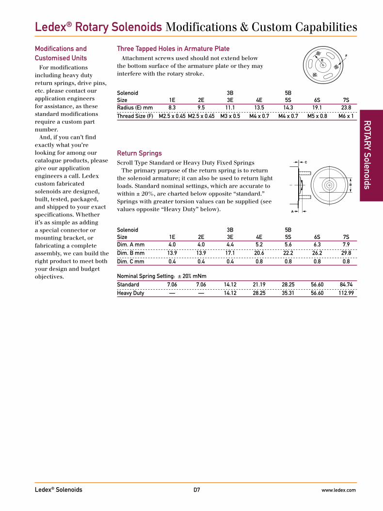
Solenoid 3B 5B Size 1E 2E 3E 4E 5S 6S 7SDim. A mm 4.0 4.0 4.4 5.2 5.6 6.3 7.9Dim. B mm 13.9 13.9 17.1 20.6 22.2 26.2 29.8Dim. C mm 0.4 0.4 0.4 0.8 0.8 0.8 0.8 Nominal Spring Setting: ± 20% mNmStandard 7.06 7.06 14.12 21.19 28.25 56.60 84.74Heavy Duty — — 14.12 28.25 35.31 56.60 112.99
Solenoid 3B 5B Size 1E 2E 3E 4E 5S 6S 7SRadius (E) mm 8.3 9.5 11.1 13.5 14.3 19.1 23.8Thread Size (F) M2.5 x 0.45 M2.5 x 0.45 M3 x 0.5 M4 x 0.7 M4 x 0.7 M5 x 0.8 M6 x 1
Ledex® Rotary Solenoids Modifications & Custom Capabilities
Three Tapped Holes in Armature PlateAttachment screws used should not extend below
the bottom surface of the armature plate or they may interfere with the rotary stroke.
FE
Return SpringsScroll Type Standard or Heavy Duty Fixed Springs
The primary purpose of the return spring is to return the solenoid armature; it can also be used to return light loads. Standard nominal settings, which are accurate to within ± 20%, are charted below opposite “standard.” Springs with greater torsion values can be supplied (see values opposite “Heavy Duty” below). A
B
C
Modifications and Customised Units
For modifications including heavy duty return springs, drive pins, etc. please contact our application engineers for assistance, as these standard modifications require a custom part number.
And, if you can’t find exactly what you’re looking for among our catalogue products, please give our application engineers a call. Ledex custom fabricated solenoids are designed, built, tested, packaged, and shipped to your exact specifications. Whether it’s as simple as adding a special connector or mounting bracket, or fabricating a complete assembly, we can build the right product to meet both your design and budget objectives.
Ledex® Solenoids www.ledex.comD8
ROT
ARY
Sol
enoi
ds
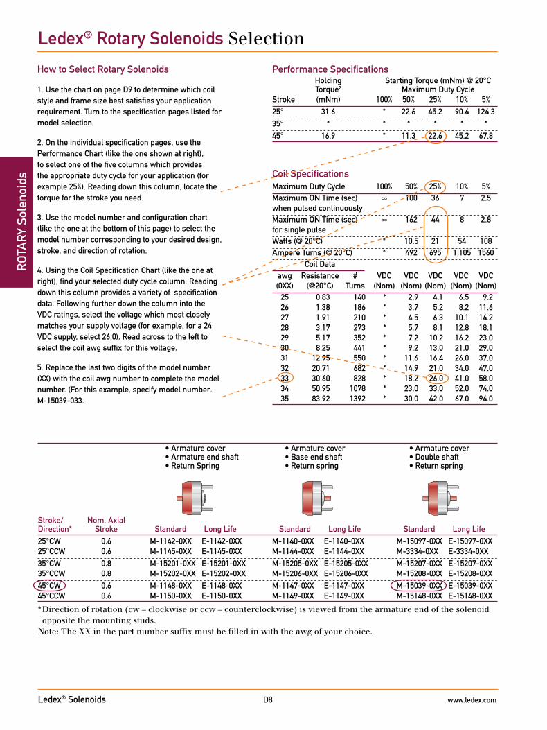
How to Select Rotary Solenoids
1. Use the chart on page D9 to determine which coil style and frame size best satisfies your application requirement. Turn to the specification pages listed for model selection.
2. On the individual specification pages, use the Performance Chart (like the one shown at right), to select one of the five columns which provides the appropriate duty cycle for your application (for example 25%). Reading down this column, locate the torque for the stroke you need.
3. Use the model number and configuration chart (like the one at the bottom of this page) to select the model number corresponding to your desired design, stroke, and direction of rotation.
4. Using the Coil Specification Chart (like the one at right), find your selected duty cycle column. Reading down this column provides a variety of specification data. Following further down the column into the VDC ratings, select the voltage which most closely matches your supply voltage (for example, for a 24 VDC supply, select 26.0). Read across to the left to select the coil awg suffix for this voltage.
5. Replace the last two digits of the model number (XX) with the coil awg number to complete the model number. (For this example, specify model number: M-15039-033.
Performance Specifications Holding Starting Torque (mNm) @ 20°C Torque2 Maximum Duty CycleStroke (mNm) 100% 50% 25% 10% 5%25° 31.6 * 22.6 45.2 90.4 124.335° * * * * * *45° 16.9 * 11.3 22.6 45.2 67.8
• Armature cover • Armature cover • Armature cover • Armature end shaft • Base end shaft • Double shaft • Return Spring • Return spring • Return spring
Stroke/ Nom. Axial Direction* Stroke Standard Long Life Standard Long Life Standard Long Life25°CW 0.6 M-1142-0XX E-1142-0XX M-1140-0XX E-1140-0XX M-15097-0XX E-15097-0XX 25°CCW 0.6 M-1145-0XX E-1145-0XX M-1144-0XX E-1144-0XX M-3334-0XX E-3334-0XX35°CW 0.8 M-15201-0XX E-15201-0XX M-15205-0XX E-15205-0XX M-15207-0XX E-15207-0XX 35°CCW 0.8 M-15202-0XX E-15202-0XX M-15206-0XX E-15206-0XX M-15208-0XX E-15208-0XX45°CW 0.6 M-1148-0XX E-1148-0XX M-1147-0XX E-1147-0XX M-15039-0XX E-15039-0XX 45°CCW 0.6 M-1150-0XX E-1150-0XX M-1149-0XX E-1149-0XX M-15148-0XX E-15148-0XX
* Direction of rotation (cw – clockwise or ccw – counterclockwise) is viewed from the armature end of the solenoid opposite the mounting studs.
Note: The XX in the part number suffix must be filled in with the awg of your choice.
Coil SpecificationsMaximum Duty Cycle 100% 50% 25% 10% 5%Maximum ON Time (sec) ∞ 100 36 7 2.5 when pulsed continuouslyMaximum ON Time (sec) ∞ 162 44 8 2.8 for single pulseWatts (@ 20°C) * 10.5 21 54 108Ampere Turns (@ 20°C) * 492 695 1,105 1560 Coil Data awg Resistance # VDC VDC VDC VDC VDC (0XX) (@20°C) Turns (Nom) (Nom) (Nom) (Nom) (Nom) 25 0.83 140 * 2.9 4.1 6.5 9.2 26 1.38 186 * 3.7 5.2 8.2 11.6 27 1.91 210 * 4.5 6.3 10.1 14.2 28 3.17 273 * 5.7 8.1 12.8 18.1 29 5.17 352 * 7.2 10.2 16.2 23.0 30 8.25 441 * 9.2 13.0 21.0 29.0 31 12.95 550 * 11.6 16.4 26.0 37.0 32 20.71 682 * 14.9 21.0 34.0 47.0 33 30.60 828 * 18.2 26.0 41.0 58.0 34 50.95 1078 * 23.0 33.0 52.0 74.0 35 83.92 1392 * 30.0 42.0 67.0 94.0
Ledex® Rotary Solenoids Selection
Ledex® Solenoids www.ledex.comD9
ROTA
RY Solenoids
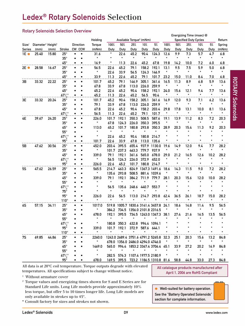
Energizing Time (msec) @ Holding Available Torque2 (mNm) Specified Duty Cycles ReturnSize/ Diameter1 Height1 Direction Torque 100% 50% 25% 10% 5% 100% 50% 25% 10% 5% SpringSeries (mm) (mm) Stroke CW CCW (mNm) Duty Duty Duty Duty Duty Duty Duty Duty Duty Duty (mNm)1E 25.40 15.80 25° • • 31.6 * 22.6 45.2 90.4 124.3 12.6 9.9 7.3 5.7 4.7 6.8 35° • • * * * * * * * * * * * * 45° • • 16.9 * 11.3 22.6 45.2 67.8 19.8 14.2 10.0 7.2 6.0 6.82E 28.58 16.67 25° • • 56.5 22.6 45.2 79.1 158.2 192.1 13.1 9.5 7.5 5.9 5.0 6.8 35° • • * 22.6 33.9 56.5 124.3 146.9 * * * * * * 45° • • 33.9 11.3 22.6 45.2 79.1 101.7 23.2 15.0 11.0 8.4 7.0 6.83B 33.32 22.22 25° • • 101.7 45.2 79.1 146.9 305.1 361.6 16.5 11.3 8.9 6.8 5.9 13.6 35° • • 67.8 33.9 67.8 113.0 226.0 259.9 * * * * * * 45° • • 45.2 22.6 45.2 90.4 158.2 192.1 24.0 15.6 12.1 9.4 7.7 13.6 671⁄2° • • 45.2 11.3 22.6 45.2 56.5 90.4 * * * * * *3E 33.32 20.24 25° • • 101.7 45.2 90.4 158.2 305.1 361.6 16.9 12.0 9.3 7.1 6.2 13.6 35° • • 79.1 33.9 67.8 113.0 226.0 259.9 * * * * * * 45° • • 67.8 22.6 45.2 90.4 158.2 203.4 29.8 17.8 13.1 10.0 8.1 13.6 671⁄2° • • 56.5 11.3 22.6 45.2 79.1 101.7 * * * * * *4E 39.67 24.20 25° • • 226.0 101.7 192.1 350.3 508.5 587.6 19.1 13.9 11.2 8.3 7.2 20.3 35° • • * 67.8 124.3 226.0 350.3 395.5 * * * * * * 45° • • 113.0 45.2 101.7 180.8 293.8 350.3 28.9 20.3 15.4 11.3 9.2 20.3 55° • * * * * * * * * * * * * 671⁄2° • • * 22.6 45.2 90.4 180.8 214.7 * * * * * * 95° • • 101.7 22.6 33.9 67.8 113.0 135.6 * * * * * *5B 47.62 30.56 25° • • 452.0 203.4 395.5 655.4 937.9 1130.0 19.6 14.9 12.0 9.4 7.7 28.2 35° • • * 101.7 237.3 463.3 779.7 937.9 * * * * * * 45° • • 339.0 79.1 192.1 361.6 565.0 678.0 29.0 21.2 16.5 12.6 10.2 28.2 671⁄2° • • * 56.5 124.3 226.0 372.9 452.0 * * * * * * 95° • • 226.0 22.6 45.2 101.7 180.8 214.7 * * * * * *5S 47.62 26.59 25° • • 565.5 214.7 463.3 824.9 1367.3 1491.6 18.6 14.3 11.5 9.0 7.2 28.2 35° • • * 135.6 293.8 508.5 881.4 1039.6 * * * * * * 45° • • 339.0 79.1 192.1 384.2 711.9 779.7 28.1 20.3 15.6 12.0 10.0 28.2 55° • • * * * * * * * * * * * * 671⁄2° • • * 56.5 135.6 248.6 440.7 553.7 * * * * * * 75° • * * * * * * * * * * * * 95° • • 226.0 22.6 56.5 113.0 214.7 293.8 62.4 36.5 26.1 18.7 15.0 28.2 110° • • * * * * * * * * * * * *6S 57.15 34.11 25° • • 1017.0 519.8 1005.7 1830.6 3141.4 3457.8 24.1 18.6 14.8 11.4 9.5 56.5 35° • • * 384.2 734.5 1356.0 2101.8 2316.5 * * * * * * 45° • • 678.0 192.1 395.5 734.5 1243.0 1367.3 38.1 27.4 21.6 16.5 13.5 56.5 55° • * * * * * * * * * * * * 671⁄2° • • * 180.8 350.3 632.8 994.4 1096.1 * * * * * * 95° • • 339.0 101.7 192.1 372.9 587.6 644.1 * * * * * * 110° • • * * * * * * * * * * * *7S 69.85 44.86 25° • • 2260.0 1243.0 2689.4 3751.6 4791.2 5265.8 32.3 25.1 20.3 15.6 13.2 84.8 35° • • * 678.0 1356.0 2486.0 4294.0 4746.0 * * * * * * 45° • • 1469.0 565.0 994.4 1853.2 3367.4 3706.4 45.1 33.9 27.2 20.2 16.9 84.8 55° • * * * * * * * * * * * * 671⁄2° • • * 282.5 576.3 1107.4 1977.5 2180.9 * * * * * * 95° • • 678.0 169.5 395.5 723.2 1186.5 1310.8 81.6 58.8 44.8 33.0 27.3 84.8
Rotary Solenoids Selection Overview
All data is at 20°C coil temperature. Torque outputs degrade with elevated temperatures. All specifications subject to change without notice. 1 Without armature cover2 Torque values and energizing times shown for S and E Series are for
Standard Life units. Long Life models provide approximately 10% less torque, but offer 5 to 10 times longer life. Long Life models are only available in strokes up to 45°.
* Consult factory for sizes and strokes not shown.
Ledex® Rotary Solenoids Selection
All catalogue products manufactured after April 1, 2006 are RoHS Compliant
Well-suited for battery operation.
See the "Battery Operated Solenoids" section for complete information.
Ledex® Solenoids www.ledex.comD10
ROT
ARY
Sol
enoi
ds
All catalogue products manufactured after April 1, 2006 are RoHS Compliant
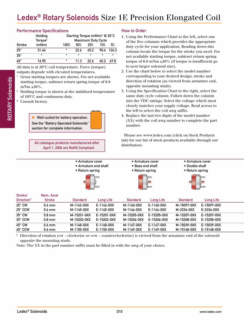
Ledex® Rotary Solenoids Size 1E Precision Elongated Coil
Performance Specifications Holding Starting Torque (mNm)1 @ 20°C Torque2 Maximum Duty CycleStroke (mNm) 100% 50% 25% 10% 5%25° 31.64 * 22.6 45.2 90.4 124.335° * * * * * *45° 16.95 * 11.3 22.6 45.2 67.8
All data is at 20°C coil temperature. Force (torque) outputs degrade with elevated temperatures.1 Gross starting torques are shown. For net available
starting torque, subtract return spring torque of 6.8 mNm ±20%.
2 Holding torque is shown at the stabilised temperature of 105°C and continuous duty.
* Consult factory.
How to Order1. Using the Performance Chart to the left, select one
of the five columns which provides the appropriate duty cycle for your application. Reading down this column locate the torque for the stroke you need. For net available starting torque, subtract return spring torque of 6.8 mNm ±20% (if torque is insufficient go to next larger solenoid size).
2. Use the chart below to select the model number corresponding to your desired design, stroke and direction of rotation (as viewed from armature end, opposite mounting studs).
3. Using the Specification Chart to the right, select the same duty cycle column. Follow down the column into the VDC ratings. Select the voltage which most closely matches your supply voltage. Read across to the left to select the coil awg suffix.
4. Replace the last two digits of the model number (XX) with the coil awg number to complete the part number.
Please see www.ledex.com (click on Stock Products tab) for our list of stock products available through our distributors.
• Armature cover • Armature cover • Armature cover • No shafts • Armature end shaft • Base end shaft • Double shaft • Armature end shaft • Base end shaft • Double shaft • 3 tapped holes • 3 tapped holes • 3 tapped holes • 3 tapped holes • Return spring • Return spring • Return spring • Return spring • Return spring • Return spring • Return spring
Stroke/ Nom. Axial Direction* Stroke Standard Long Life Standard Long Life Standard Long Life Standard Long Life Standard Long Life Standard Long Life Standard Long Life25° CW 0.6 mm M-1142-0XX E-1142-0XX M-1140-0XX E-1140-0XX M-15097-0XX E-15097-0XX M-1143-0XX E-1143-0XX M-15089-0XX E-15089-0XX M-15211-0XX E-15211-0XX M-15215-0XX E-15215-0XX 25° CCW 0.6 mm M-1145-0XX E-1145-0XX M-1144-0XX E-1144-0XX M-3334-0XX E-3334-0XX M-1146-0XX E-1146-0XX M-3311-0XX E-3311-0XX M-15084-0XX E-15084-0XX M-15216-0XX E-15216-0XX35° CW 0.8 mm M-15201-0XX E-15201-0XX M-15205-0XX E-15205-0XX M-15207-0XX E-15207-0XX M-15200-0XX E-15200-0XX M-15204-0XX E-15204-0XX M-15212-0XX E-15212-0XX M-1305-0XX E-1305-0XX 35° CCW 0.8 mm M-15202-0XX E-15202-0XX M-15206-0XX E-15206-0XX M-15208-0XX E-15208-0XX M-15203-0XX E-15203-0XX M-15210-0XX E-15210-0XX M-15213-0XX E-15213-0XX M-15217-0XX E-15217-0XX45° CW 0.6 mm M-1148-0XX E-1148-0XX M-1147-0XX E-1147-0XX M-15039-0XX E-15039-0XX M-1141-0XX E-1141-0XX M-3380-0XX E-3380-0XX M-15085-0XX E-15085-0XX M-15218-0XX E-15218-0XX 45° CCW 0.6 mm M-1150-0XX E-1150-0XX M-1149-0XX E-1149-0XX M-15148-0XX E-15148-0XX M-1151-0XX E-1151-0XX M-1282-0XX E-1282-0XX M-15214-0XX E-15214-0XX M-15219-0XX E-15219-0XX
* Direction of rotation (cw – clockwise or ccw – counterclockwise) is viewed from the armature end of the solenoid opposite the mounting studs.
Note: The XX in the part number suffix must be filled in with the awg of your choice.
Well-suited for battery operation.
See the "Battery Operated Solenoids" section for complete information.

Ledex® Solenoids www.ledex.comD11
ROTA
RY Solenoids
All specifications subject to change without notice.
General SpecificationsDielectric Strength 1000 VRMS, all coilsRecommended Maximum watts dissipatedMinimum Heat Sink by solenoid are based on an
unrestricted flow of air at 20°C, with solenoid mounted on the equivalent of an aluminium plate measuring 76.2 mm square by 3.2 mm thick.
Coil Resistance ±5% toleranceStarting Torque Gross torque values are shown. For
net starting torque, subtract return spring torque
Return Spring Torque 6.8 mNm ±20%Weight 42.5 gDimensions See page D28
• Armature cover • Armature cover • Armature cover • No shafts • Armature end shaft • Base end shaft • Double shaft • Armature end shaft • Base end shaft • Double shaft • 3 tapped holes • 3 tapped holes • 3 tapped holes • 3 tapped holes • Return spring • Return spring • Return spring • Return spring • Return spring • Return spring • Return spring
Stroke/ Nom. Axial Direction* Stroke Standard Long Life Standard Long Life Standard Long Life Standard Long Life Standard Long Life Standard Long Life Standard Long Life25° CW 0.6 mm M-1142-0XX E-1142-0XX M-1140-0XX E-1140-0XX M-15097-0XX E-15097-0XX M-1143-0XX E-1143-0XX M-15089-0XX E-15089-0XX M-15211-0XX E-15211-0XX M-15215-0XX E-15215-0XX 25° CCW 0.6 mm M-1145-0XX E-1145-0XX M-1144-0XX E-1144-0XX M-3334-0XX E-3334-0XX M-1146-0XX E-1146-0XX M-3311-0XX E-3311-0XX M-15084-0XX E-15084-0XX M-15216-0XX E-15216-0XX35° CW 0.8 mm M-15201-0XX E-15201-0XX M-15205-0XX E-15205-0XX M-15207-0XX E-15207-0XX M-15200-0XX E-15200-0XX M-15204-0XX E-15204-0XX M-15212-0XX E-15212-0XX M-1305-0XX E-1305-0XX 35° CCW 0.8 mm M-15202-0XX E-15202-0XX M-15206-0XX E-15206-0XX M-15208-0XX E-15208-0XX M-15203-0XX E-15203-0XX M-15210-0XX E-15210-0XX M-15213-0XX E-15213-0XX M-15217-0XX E-15217-0XX45° CW 0.6 mm M-1148-0XX E-1148-0XX M-1147-0XX E-1147-0XX M-15039-0XX E-15039-0XX M-1141-0XX E-1141-0XX M-3380-0XX E-3380-0XX M-15085-0XX E-15085-0XX M-15218-0XX E-15218-0XX 45° CCW 0.6 mm M-1150-0XX E-1150-0XX M-1149-0XX E-1149-0XX M-15148-0XX E-15148-0XX M-1151-0XX E-1151-0XX M-1282-0XX E-1282-0XX M-15214-0XX E-15214-0XX M-15219-0XX E-15219-0XX
* Direction of rotation (cw – clockwise or ccw – counterclockwise) is viewed from the armature end of the solenoid opposite the mounting studs.
Note: The XX in the part number suffix must be filled in with the awg of your choice.
Coil SpecificationsMaximum Duty Cycle 100% 50% 25% 10% 5%Maximum ON Time (sec) ∞ 100 36 7 2.5 when pulsed continuously1
Maximum ON Time (sec) ∞ 162 44 8 2.8 for single pulse2
Watts (@ 20°C) * 10.5 21 54 108Ampere Turns (@ 20°C) * 492 695 1105 1560 Coil Data awg Resistance # VDC VDC VDC VDC VDC (0XX)3 (@20°C) Turns4 (Nom) (Nom) (Nom) (Nom) (Nom) 25 0.83 140 * 2.9 4.1 6.5 9.2 26 1.38 186 * 3.7 5.2 8.2 11.6 27 1.91 210 * 4.5 6.3 10.1 14.2 28 3.17 273 * 5.7 8.1 12.8 18.1 29 5.17 352 * 7.2 10.2 16.2 23.0 30 8.25 441 * 9.2 13.0 21.0 29.0 31 12.95 550 * 11.6 16.4 26.0 37.0 32 20.71 682 * 14.9 21.0 34.0 47.0 33 30.60 828 * 18.2 26.0 41.0 58.0 34 50.95 1078 * 23.0 33.0 52.0 74.0 35 83.92 1392 * 30.0 42.0 67.0 94.0
1 Continuously pulsed at stated watts and duty cycle.2 Single pulse at stated watts (with coil at ambient room
temperature 20°C).3 Other coil awg sizes available, consult factory.4 Reference number of turns.* Consult factory.
Ledex® Rotary Solenoids Size 1E Precision Elongated Coil

Ledex® Solenoids www.ledex.comD12
ROT
ARY
Sol
enoi
ds
All catalogue products manufactured after April 1, 2006 are RoHS Compliant
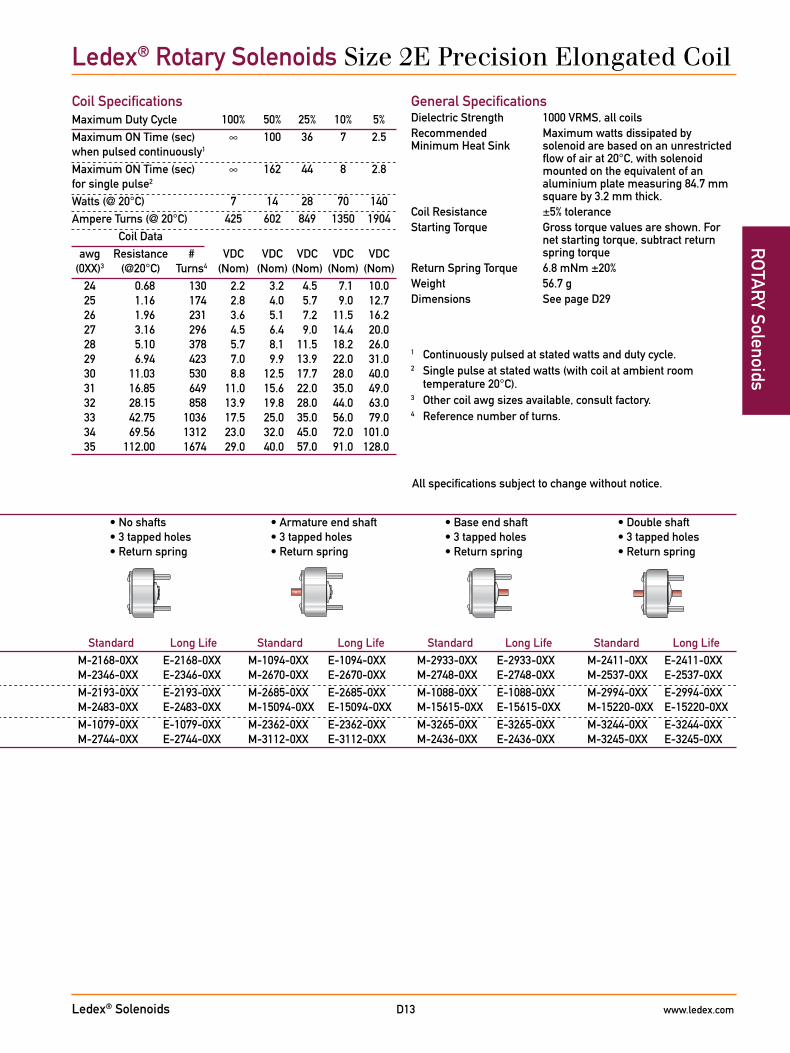
Ledex® Rotary Solenoids Size 2E Precision Elongated Coil
Performance Specifications Holding Starting Torque (mNm)1 @ 20°C Torque2 Maximum Duty CycleStroke (mNm) 100% 50% 25% 10% 5%25° 56.5 22.6 45.2 79.1 158.2 192.1735° * 22.6 33.9 56.5 124.3 146.945° 33.9 11.3 22.6 45.2 79.1 101.7
All data is at 20°C coil temperature. Force (torque) outputs degrade with elevated temperatures.1 Gross starting torques are shown. For net available
starting torque, subtract return spring torque of 6.8 mNm ±20%.
2 Holding torque is shown at the stabilised temperature of 105°C and continuous duty.
* Consult factory.
How to Order1. Using the Performance Chart to the left, select one
of the five columns which provides the appropriate duty cycle for your application. Reading down this column locate the torque for the stroke you need. For net available starting torque, subtract return spring torque of 6.8 mNm ±20% (if torque is insufficient go to next larger solenoid size).
2. Use the chart below to select the model number corresponding to your desired design, stroke and direction of rotation (as viewed from armature end, opposite mounting studs).
3. Using the Specification Chart to the right, select the same duty cycle column. Follow down the column into the VDC ratings. Select the voltage which most closely matches your supply voltage. Read across to the left to select the coil awg suffix.
4. Replace the last two digits of the model number (XX) with the coil awg number to complete the part number.
Please see www.ledex.com (click on Stock Products tab) for our list of stock products available through our distributors.
• Armature cover • Armature cover • Armature cover • No shafts • Armature end shaft • Base end shaft • Double shaft • Armature end shaft • Base end shaft • Double shaft • 3 tapped holes • 3 tapped holes • 3 tapped holes • 3 tapped holes • Return spring • Return spring • Return spring • Return spring • Return spring • Return spring • Return spring
Stroke/ Nom. Axial Direction* Stroke Standard Long Life Standard Long Life Standard Long Life Standard Long Life Standard Long Life Standard Long Life Standard Long Life25° CW 0.6 mm M-1244-0XX E-1244-0XX M-1024-0XX E-1024-0XX M-2390-0XX E-2390-0XX M-2168-0XX E-2168-0XX M-1094-0XX E-1094-0XX M-2933-0XX E-2933-0XX M-2411-0XX E-2411-0XX 25° CCW 0.6 mm M-3259-0XX E-3259-0XX M-2452-0XX E-2452-0XX M-2389-0XX E-2389-0XX M-2346-0XX E-2346-0XX M-2670-0XX E-2670-0XX M-2748-0XX E-2748-0XX M-2537-0XX E-2537-0XX35° CW 0.6 mm M-1294-0XX E-1294-0XX M-2116-0XX E-2116-0XX M-3405-0XX E-3405-0XX M-2193-0XX E-2193-0XX M-2685-0XX E-2685-0XX M-1088-0XX E-1088-0XX M-2994-0XX E-2994-0XX 35° CCW 0.6 mm M-1159-0XX E-1159-0XX M-15004-0XX E-15004-0XX M-15111-0XX E-15111-0XX M-2483-0XX E-2483-0XX M-15094-0XX E-15094-0XX M-15615-0XX E-15615-0XX M-15220-0XX E-15220-0XX45° CW 0.6 mm M-2264-0XX E-2264-0XX M-2117-0XX E-2117-0XX M-1344-0XX E-1344-0XX M-1079-0XX E-1079-0XX M-2362-0XX E-2362-0XX M-3265-0XX E-3265-0XX M-3244-0XX E-3244-0XX 45° CCW 0.6 mm M-2265-0XX E-2265-0XX M-2450-0XX E-2450-0XX M-15046-0XX E-15046-0XX M-2744-0XX E-2744-0XX M-3112-0XX E-3112-0XX M-2436-0XX E-2436-0XX M-3245-0XX E-3245-0XX
* Direction of rotation (cw – clockwise or ccw – counterclockwise) is viewed from the armature end of the solenoid opposite the mounting studs.
Note: The XX in the part number suffix must be filled in with the awg of your choice.
Well-suited for battery operation.
See the "Battery Operated Solenoids" section for complete information.
Ledex® Solenoids www.ledex.comD13
ROTA
RY Solenoids
All specifications subject to change without notice.
General SpecificationsDielectric Strength 1000 VRMS, all coilsRecommended Maximum watts dissipated byMinimum Heat Sink solenoid are based on an unrestricted
flow of air at 20°C, with solenoid mounted on the equivalent of an aluminium plate measuring 84.7 mm square by 3.2 mm thick.
Coil Resistance ±5% toleranceStarting Torque Gross torque values are shown. For
net starting torque, subtract return spring torque
Return Spring Torque 6.8 mNm ±20%Weight 56.7 gDimensions See page D29
• Armature cover • Armature cover • Armature cover • No shafts • Armature end shaft • Base end shaft • Double shaft • Armature end shaft • Base end shaft • Double shaft • 3 tapped holes • 3 tapped holes • 3 tapped holes • 3 tapped holes • Return spring • Return spring • Return spring • Return spring • Return spring • Return spring • Return spring
Stroke/ Nom. Axial Direction* Stroke Standard Long Life Standard Long Life Standard Long Life Standard Long Life Standard Long Life Standard Long Life Standard Long Life25° CW 0.6 mm M-1244-0XX E-1244-0XX M-1024-0XX E-1024-0XX M-2390-0XX E-2390-0XX M-2168-0XX E-2168-0XX M-1094-0XX E-1094-0XX M-2933-0XX E-2933-0XX M-2411-0XX E-2411-0XX 25° CCW 0.6 mm M-3259-0XX E-3259-0XX M-2452-0XX E-2452-0XX M-2389-0XX E-2389-0XX M-2346-0XX E-2346-0XX M-2670-0XX E-2670-0XX M-2748-0XX E-2748-0XX M-2537-0XX E-2537-0XX35° CW 0.6 mm M-1294-0XX E-1294-0XX M-2116-0XX E-2116-0XX M-3405-0XX E-3405-0XX M-2193-0XX E-2193-0XX M-2685-0XX E-2685-0XX M-1088-0XX E-1088-0XX M-2994-0XX E-2994-0XX 35° CCW 0.6 mm M-1159-0XX E-1159-0XX M-15004-0XX E-15004-0XX M-15111-0XX E-15111-0XX M-2483-0XX E-2483-0XX M-15094-0XX E-15094-0XX M-15615-0XX E-15615-0XX M-15220-0XX E-15220-0XX45° CW 0.6 mm M-2264-0XX E-2264-0XX M-2117-0XX E-2117-0XX M-1344-0XX E-1344-0XX M-1079-0XX E-1079-0XX M-2362-0XX E-2362-0XX M-3265-0XX E-3265-0XX M-3244-0XX E-3244-0XX 45° CCW 0.6 mm M-2265-0XX E-2265-0XX M-2450-0XX E-2450-0XX M-15046-0XX E-15046-0XX M-2744-0XX E-2744-0XX M-3112-0XX E-3112-0XX M-2436-0XX E-2436-0XX M-3245-0XX E-3245-0XX
* Direction of rotation (cw – clockwise or ccw – counterclockwise) is viewed from the armature end of the solenoid opposite the mounting studs.
Note: The XX in the part number suffix must be filled in with the awg of your choice.
Coil SpecificationsMaximum Duty Cycle 100% 50% 25% 10% 5%Maximum ON Time (sec) ∞ 100 36 7 2.5 when pulsed continuously1
Maximum ON Time (sec) ∞ 162 44 8 2.8 for single pulse2
Watts (@ 20°C) 7 14 28 70 140Ampere Turns (@ 20°C) 425 602 849 1350 1904 Coil Data awg Resistance # VDC VDC VDC VDC VDC (0XX)3 (@20°C) Turns4 (Nom) (Nom) (Nom) (Nom) (Nom) 24 0.68 130 2.2 3.2 4.5 7.1 10.0 25 1.16 174 2.8 4.0 5.7 9.0 12.7 26 1.96 231 3.6 5.1 7.2 11.5 16.2 27 3.16 296 4.5 6.4 9.0 14.4 20.0 28 5.10 378 5.7 8.1 11.5 18.2 26.0 29 6.94 423 7.0 9.9 13.9 22.0 31.0 30 11.03 530 8.8 12.5 17.7 28.0 40.0 31 16.85 649 11.0 15.6 22.0 35.0 49.0 32 28.15 858 13.9 19.8 28.0 44.0 63.0 33 42.75 1036 17.5 25.0 35.0 56.0 79.0 34 69.56 1312 23.0 32.0 45.0 72.0 101.0 35 112.00 1674 29.0 40.0 57.0 91.0 128.0
1 Continuously pulsed at stated watts and duty cycle.2 Single pulse at stated watts (with coil at ambient room
temperature 20°C).3 Other coil awg sizes available, consult factory.4 Reference number of turns.
Ledex® Rotary Solenoids Size 2E Precision Elongated Coil
Ledex® Solenoids www.ledex.comD14
ROT
ARY
Sol
enoi
ds
All catalogue products manufactured after April 1, 2006 are RoHS Compliant
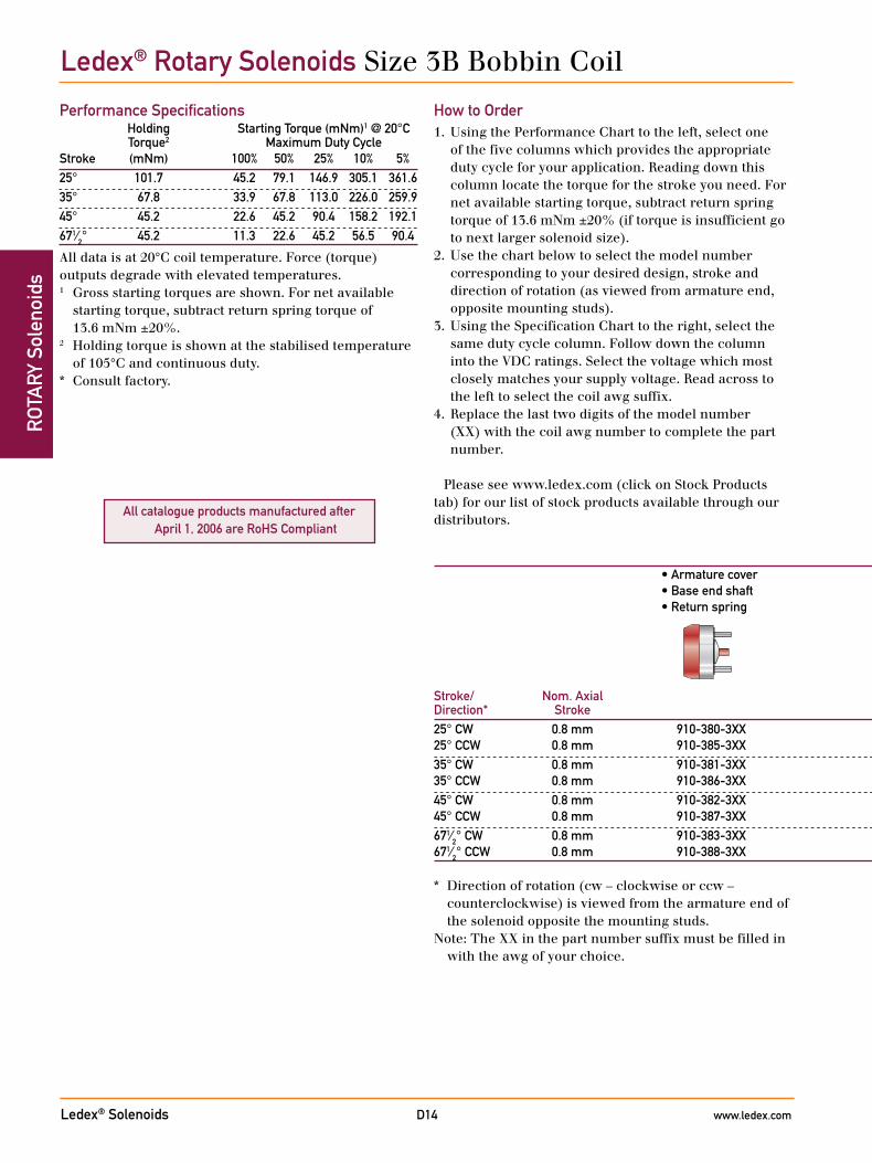
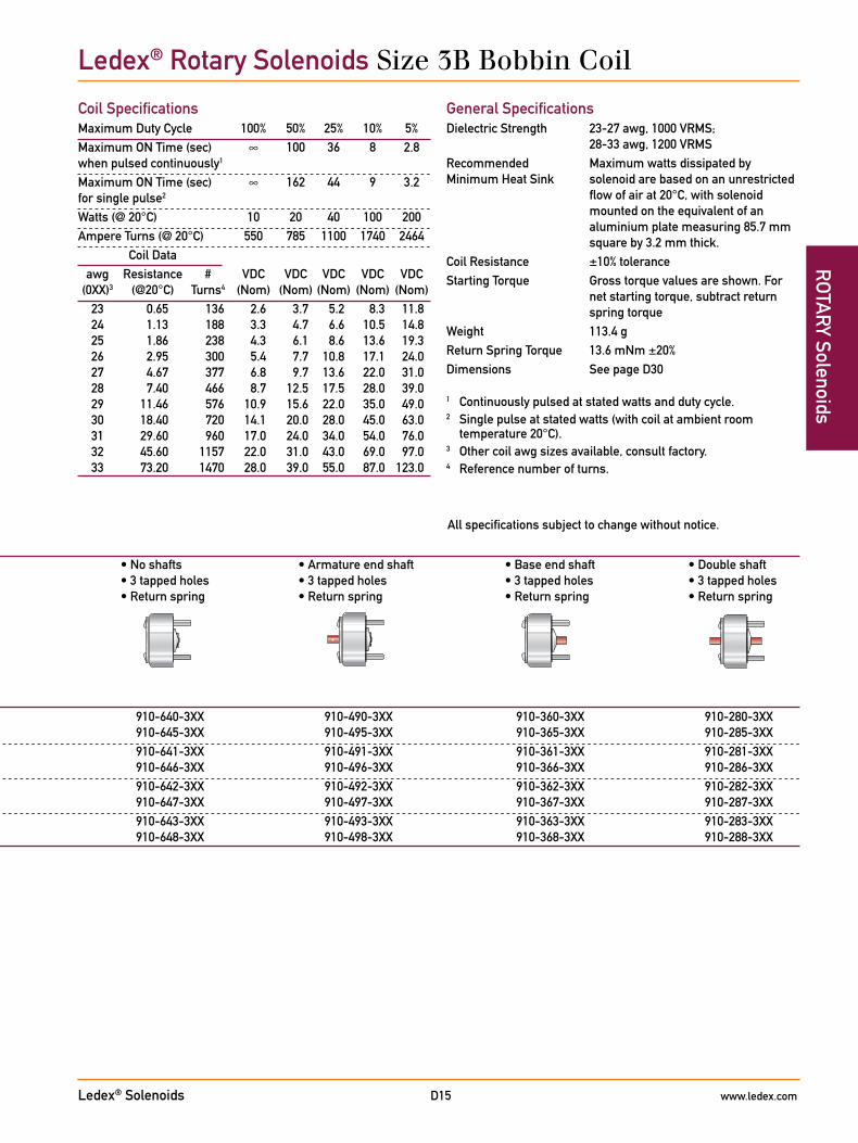
Ledex® Rotary Solenoids Size 3B Bobbin Coil
Performance Specifications Holding Starting Torque (mNm)1 @ 20°C Torque2 Maximum Duty CycleStroke (mNm) 100% 50% 25% 10% 5%25° 101.7 45.2 79.1 146.9 305.1 361.635° 67.8 33.9 67.8 113.0 226.0 259.945° 45.2 22.6 45.2 90.4 158.2 192.1671⁄2° 45.2 11.3 22.6 45.2 56.5 90.4
All data is at 20°C coil temperature. Force (torque) outputs degrade with elevated temperatures.1 Gross starting torques are shown. For net available
starting torque, subtract return spring torque of 13.6 mNm ±20%.
2 Holding torque is shown at the stabilised temperature of 105°C and continuous duty.
* Consult factory.
How to Order1. Using the Performance Chart to the left, select one
of the five columns which provides the appropriate duty cycle for your application. Reading down this column locate the torque for the stroke you need. For net available starting torque, subtract return spring torque of 13.6 mNm ±20% (if torque is insufficient go to next larger solenoid size).
2. Use the chart below to select the model number corresponding to your desired design, stroke and direction of rotation (as viewed from armature end, opposite mounting studs).
3. Using the Specification Chart to the right, select the same duty cycle column. Follow down the column into the VDC ratings. Select the voltage which most closely matches your supply voltage. Read across to the left to select the coil awg suffix.
4. Replace the last two digits of the model number (XX) with the coil awg number to complete the part number.
Please see www.ledex.com (click on Stock Products tab) for our list of stock products available through our distributors.
• Armature cover • No shafts • Armature end shaft • Base end shaft • Double shaft • Base end shaft • 3 tapped holes • 3 tapped holes • 3 tapped holes • 3 tapped holes • Return spring • Return spring • Return spring • Return spring • Return spring
Stroke/ Nom. Axial Direction* Stroke25° CW 0.8 mm 910-380-3XX 910-640-3XX 910-490-3XX 910-360-3XX 910-280-3XX 25° CCW 0.8 mm 910-385-3XX 910-645-3XX 910-495-3XX 910-365-3XX 910-285-3XX35° CW 0.8 mm 910-381-3XX 910-641-3XX 910-491-3XX 910-361-3XX 910-281-3XX 35° CCW 0.8 mm 910-386-3XX 910-646-3XX 910-496-3XX 910-366-3XX 910-286-3XX45° CW 0.8 mm 910-382-3XX 910-642-3XX 910-492-3XX 910-362-3XX 910-282-3XX 45° CCW 0.8 mm 910-387-3XX 910-647-3XX 910-497-3XX 910-367-3XX 910-287-3XX671⁄2° CW 0.8 mm 910-383-3XX 910-643-3XX 910-493-3XX 910-363-3XX 910-283-3XX 671⁄2° CCW 0.8 mm 910-388-3XX 910-648-3XX 910-498-3XX 910-368-3XX 910-288-3XX
* Direction of rotation (cw – clockwise or ccw – counterclockwise) is viewed from the armature end of the solenoid opposite the mounting studs.
Note: The XX in the part number suffix must be filled in with the awg of your choice.
Ledex® Solenoids www.ledex.comD15
ROTA
RY Solenoids
All specifications subject to change without notice.
Coil SpecificationsMaximum Duty Cycle 100% 50% 25% 10% 5%Maximum ON Time (sec) ∞ 100 36 8 2.8 when pulsed continuously1
Maximum ON Time (sec) ∞ 162 44 9 3.2 for single pulse2
Watts (@ 20°C) 10 20 40 100 200Ampere Turns (@ 20°C) 550 785 1100 1740 2464 Coil Data awg Resistance # VDC VDC VDC VDC VDC (0XX)3 (@20°C) Turns4 (Nom) (Nom) (Nom) (Nom) (Nom) 23 0.65 136 2.6 3.7 5.2 8.3 11.8 24 1.13 188 3.3 4.7 6.6 10.5 14.8 25 1.86 238 4.3 6.1 8.6 13.6 19.3 26 2.95 300 5.4 7.7 10.8 17.1 24.0 27 4.67 377 6.8 9.7 13.6 22.0 31.0 28 7.40 466 8.7 12.5 17.5 28.0 39.0 29 11.46 576 10.9 15.6 22.0 35.0 49.0 30 18.40 720 14.1 20.0 28.0 45.0 63.0 31 29.60 960 17.0 24.0 34.0 54.0 76.0 32 45.60 1157 22.0 31.0 43.0 69.0 97.0 33 73.20 1470 28.0 39.0 55.0 87.0 123.0
General SpecificationsDielectric Strength 23-27 awg, 1000 VRMS;
28-33 awg, 1200 VRMSRecommended Maximum watts dissipated byMinimum Heat Sink solenoid are based on an unrestricted
flow of air at 20°C, with solenoid mounted on the equivalent of an aluminium plate measuring 85.7 mm square by 3.2 mm thick.
Coil Resistance ±10% toleranceStarting Torque Gross torque values are shown. For
net starting torque, subtract return spring torque
Weight 113.4 gReturn Spring Torque 13.6 mNm ±20%Dimensions See page D30
1 Continuously pulsed at stated watts and duty cycle.2 Single pulse at stated watts (with coil at ambient room
temperature 20°C).3 Other coil awg sizes available, consult factory.4 Reference number of turns.
• Armature cover • No shafts • Armature end shaft • Base end shaft • Double shaft • Base end shaft • 3 tapped holes • 3 tapped holes • 3 tapped holes • 3 tapped holes • Return spring • Return spring • Return spring • Return spring • Return spring
Stroke/ Nom. Axial Direction* Stroke25° CW 0.8 mm 910-380-3XX 910-640-3XX 910-490-3XX 910-360-3XX 910-280-3XX 25° CCW 0.8 mm 910-385-3XX 910-645-3XX 910-495-3XX 910-365-3XX 910-285-3XX35° CW 0.8 mm 910-381-3XX 910-641-3XX 910-491-3XX 910-361-3XX 910-281-3XX 35° CCW 0.8 mm 910-386-3XX 910-646-3XX 910-496-3XX 910-366-3XX 910-286-3XX45° CW 0.8 mm 910-382-3XX 910-642-3XX 910-492-3XX 910-362-3XX 910-282-3XX 45° CCW 0.8 mm 910-387-3XX 910-647-3XX 910-497-3XX 910-367-3XX 910-287-3XX671⁄2° CW 0.8 mm 910-383-3XX 910-643-3XX 910-493-3XX 910-363-3XX 910-283-3XX 671⁄2° CCW 0.8 mm 910-388-3XX 910-648-3XX 910-498-3XX 910-368-3XX 910-288-3XX
Ledex® Rotary Solenoids Size 3B Bobbin Coil
Ledex® Solenoids www.ledex.comD16
ROT
ARY
Sol
enoi
ds
All catalogue products manufactured after April 1, 2006 are RoHS Compliant
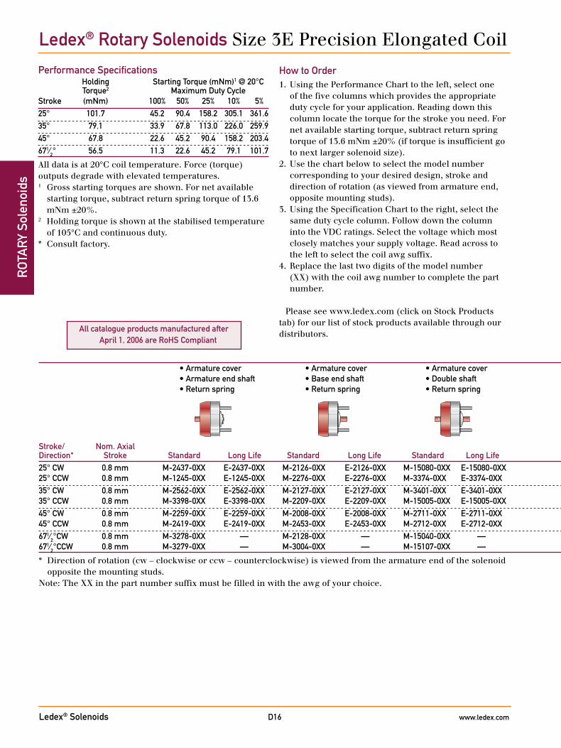
Ledex® Rotary Solenoids Size 3E Precision Elongated Coil
Performance Specifications Holding Starting Torque (mNm)1 @ 20°C Torque2 Maximum Duty CycleStroke (mNm) 100% 50% 25% 10% 5%25° 101.7 45.2 90.4 158.2 305.1 361.635° 79.1 33.9 67.8 113.0 226.0 259.945° 67.8 22.6 45.2 90.4 158.2 203.4671⁄2° 56.5 11.3 22.6 45.2 79.1 101.7
All data is at 20°C coil temperature. Force (torque) outputs degrade with elevated temperatures.1 Gross starting torques are shown. For net available
starting torque, subtract return spring torque of 13.6 mNm ±20%.
2 Holding torque is shown at the stabilised temperature of 105°C and continuous duty.
* Consult factory.
How to Order1. Using the Performance Chart to the left, select one
of the five columns which provides the appropriate duty cycle for your application. Reading down this column locate the torque for the stroke you need. For net available starting torque, subtract return spring torque of 13.6 mNm ±20% (if torque is insufficient go to next larger solenoid size).
2. Use the chart below to select the model number corresponding to your desired design, stroke and direction of rotation (as viewed from armature end, opposite mounting studs).
3. Using the Specification Chart to the right, select the same duty cycle column. Follow down the column into the VDC ratings. Select the voltage which most closely matches your supply voltage. Read across to the left to select the coil awg suffix.
4. Replace the last two digits of the model number (XX) with the coil awg number to complete the part number.
Please see www.ledex.com (click on Stock Products tab) for our list of stock products available through our distributors.
• Armature cover • Armature cover • Armature cover • No shafts • Armature end shaft • Base end shaft • Double shaft • Armature end shaft • Base end shaft • Double shaft • 3 tapped holes • 3 tapped holes • 3 tapped holes • 3 tapped holes • Return spring • Return spring • Return spring • Return spring • Return spring • Return spring • Return spring
Stroke/ Nom. Axial Direction* Stroke Standard Long Life Standard Long Life Standard Long Life Standard Long Life Standard Long Life Standard Long Life Standard Long Life25° CW 0.8 mm M-2437-0XX E-2437-0XX M-2126-0XX E-2126-0XX M-15080-0XX E-15080-0XX M-1075-0XX E-1075-0XX M-2512-0XX E-2512-0XX M-3169-0XX E-3169-0XX M-2412-0XX E-2412-0XX 25° CCW 0.8 mm M-1245-0XX E-1245-0XX M-2276-0XX E-2276-0XX M-3374-0XX E-3374-0XX M-2159-0XX E-2159-0XX M-2992-0XX E-2992-0XX M-2978-0XX E-2978-0XX M-15128-0XX E-15128-0XX35° CW 0.8 mm M-2562-0XX E-2562-0XX M-2127-0XX E-2127-0XX M-3401-0XX E-3401-0XX M-2216-0XX E-2216-0XX M-2634-0XX E-2634-0XX M-2330-0XX E-2330-0XX M-2722-0XX E-2722-0XX 35° CCW 0.8 mm M-3398-0XX E-3398-0XX M-2209-0XX E-2209-0XX M-15005-0XX E-15005-0XX M-2444-0XX E-2444-0XX M-3044-0XX E-3044-0XX M-15221-0XX E-152221-0XX M-2723-0XX E-2723-0XX45° CW 0.8 mm M-2259-0XX E-2259-0XX M-2008-0XX E-2008-0XX M-2711-0XX E-2711-0XX M-2556-0XX E-2556-0XX M-3045-0XX E-3045-0XX M-1135-0XX E-1135-0XX M-2616-0XX E-2616-0XX 45° CCW 0.8 mm M-2419-0XX E-2419-0XX M-2453-0XX E-2453-0XX M-2712-0XX E-2712-0XX M-2268-0XX E-2268-0XX M-2906-0XX E-2906-0XX M-2613-0XX E-2613-0XX M-15020-0XX E-15020-0XX671⁄2°CW 0.8 mm M-3278-0XX — M-2128-0XX — M-15040-0XX — M-2289-0XX — M-2550-0XX — M-15071-0XX — M-2542-0XX — 671⁄2°CCW 0.8 mm M-3279-0XX — M-3004-0XX — M-15107-0XX — M-2288-0XX — M-1330-0XX — M-3381-0XX — M-2940-0XX —
* Direction of rotation (cw – clockwise or ccw – counterclockwise) is viewed from the armature end of the solenoid opposite the mounting studs.
Note: The XX in the part number suffix must be filled in with the awg of your choice.

Ledex® Solenoids www.ledex.comD17
ROTA
RY Solenoids
All specifications subject to change without notice.
Coil SpecificationsMaximum Duty Cycle 100% 50% 25% 10% 5%Maximum ON Time (sec) ∞ 100 36 8 2.8 when pulsed continuously1
Maximum ON Time (sec) ∞ 162 44 9 3.2 for single pulse2
Watts (@ 20°C) 9 18 36 90 180Ampere Turns (@ 20°C) 535 756 1070 1690 2397 Coil Data awg Resistance # VDC VDC VDC VDC VDC (0XX)3 (@20°C) Turns4 (Nom) (Nom) (Nom) (Nom) (Nom) 23 0.70 145 2.6 3.7 5.2 8.2 11.6 24 1.18 192 3.3 4.6 6.6 10.4 14.7 25 1.97 252 4.2 5.9 8.4 13.2 18.7 26 3.26 328 5.3 7.5 10.6 16.8 24.0 27 5.04 405 6.7 9.4 13.3 21.0 30.0 28 8.02 510 8.4 11.9 16.8 27.0 38.0 29 12.21 627 10.4 14.7 21.0 33.0 47.0 30 19.20 780 13.2 18.6 26.0 42.0 59.0 31 31.84 1008 16.9 24.0 34.0 53.0 76.0 32 46.97 1215 21.0 29.0 41.0 65.0 93.0 33 75.30 1530 26.0 37.0 53.0 83.0 118.0
General SpecificationsDielectric Strength 23-27 awg, 1000 VRMS;
28-33 awg, 1200 VRMSRecommended Maximum watts dissipatedMinimum Heat Sink by solenoid are based on an
unrestricted flow of air at 20°C, with solenoid mounted on the equivalent of an aluminium plate measuring 117.5 mm square by 3.2 thick.
Coil Resistance ±5% toleranceStarting Torque Gross torque values are shown. For
net starting torque, subtract return spring torque
Return Spring Torque 13.6 mNm ±20%Weight 99.2 gDimensions See page D31
• Armature cover • Armature cover • Armature cover • No shafts • Armature end shaft • Base end shaft • Double shaft • Armature end shaft • Base end shaft • Double shaft • 3 tapped holes • 3 tapped holes • 3 tapped holes • 3 tapped holes • Return spring • Return spring • Return spring • Return spring • Return spring • Return spring • Return spring
Stroke/ Nom. Axial Direction* Stroke Standard Long Life Standard Long Life Standard Long Life Standard Long Life Standard Long Life Standard Long Life Standard Long Life25° CW 0.8 mm M-2437-0XX E-2437-0XX M-2126-0XX E-2126-0XX M-15080-0XX E-15080-0XX M-1075-0XX E-1075-0XX M-2512-0XX E-2512-0XX M-3169-0XX E-3169-0XX M-2412-0XX E-2412-0XX 25° CCW 0.8 mm M-1245-0XX E-1245-0XX M-2276-0XX E-2276-0XX M-3374-0XX E-3374-0XX M-2159-0XX E-2159-0XX M-2992-0XX E-2992-0XX M-2978-0XX E-2978-0XX M-15128-0XX E-15128-0XX35° CW 0.8 mm M-2562-0XX E-2562-0XX M-2127-0XX E-2127-0XX M-3401-0XX E-3401-0XX M-2216-0XX E-2216-0XX M-2634-0XX E-2634-0XX M-2330-0XX E-2330-0XX M-2722-0XX E-2722-0XX 35° CCW 0.8 mm M-3398-0XX E-3398-0XX M-2209-0XX E-2209-0XX M-15005-0XX E-15005-0XX M-2444-0XX E-2444-0XX M-3044-0XX E-3044-0XX M-15221-0XX E-152221-0XX M-2723-0XX E-2723-0XX45° CW 0.8 mm M-2259-0XX E-2259-0XX M-2008-0XX E-2008-0XX M-2711-0XX E-2711-0XX M-2556-0XX E-2556-0XX M-3045-0XX E-3045-0XX M-1135-0XX E-1135-0XX M-2616-0XX E-2616-0XX 45° CCW 0.8 mm M-2419-0XX E-2419-0XX M-2453-0XX E-2453-0XX M-2712-0XX E-2712-0XX M-2268-0XX E-2268-0XX M-2906-0XX E-2906-0XX M-2613-0XX E-2613-0XX M-15020-0XX E-15020-0XX671⁄2°CW 0.8 mm M-3278-0XX — M-2128-0XX — M-15040-0XX — M-2289-0XX — M-2550-0XX — M-15071-0XX — M-2542-0XX — 671⁄2°CCW 0.8 mm M-3279-0XX — M-3004-0XX — M-15107-0XX — M-2288-0XX — M-1330-0XX — M-3381-0XX — M-2940-0XX —
* Direction of rotation (cw – clockwise or ccw – counterclockwise) is viewed from the armature end of the solenoid opposite the mounting studs.
Note: The XX in the part number suffix must be filled in with the awg of your choice.
1 Continuously pulsed at stated watts and duty cycle.2 Single pulse at stated watts (with coil at ambient room
temperature 20°C).3 Other coil awg sizes available, consult factory.4 Reference number of turns.
Ledex® Rotary Solenoids Size 3E Precision Elongated Coil
Ledex® Solenoids www.ledex.comD18
ROT
ARY
Sol
enoi
ds
All catalogue products manufactured after April 1, 2006 are RoHS Compliant
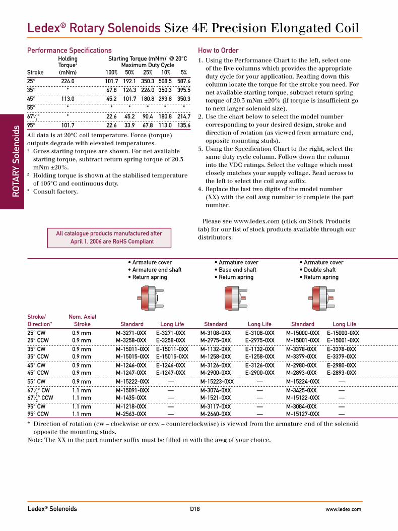
Performance Specifications Holding Starting Torque (mNm)1 @ 20°C Torque2 Maximum Duty CycleStroke (mNm) 100% 50% 25% 10% 5%25° 226.0 101.7 192.1 350.3 508.5 587.635° * 67.8 124.3 226.0 350.3 395.545° 113.0 45.2 101.7 180.8 293.8 350.355° * * * * * *671⁄2° * 22.6 45.2 90.4 180.8 214.795° 101.7 22.6 33.9 67.8 113.0 135.6
All data is at 20°C coil temperature. Force (torque) outputs degrade with elevated temperatures.1 Gross starting torques are shown. For net available
starting torque, subtract return spring torque of 20.3 mNm ±20%.
2 Holding torque is shown at the stabilised temperature of 105°C and continuous duty.
* Consult factory.
Ledex® Rotary Solenoids Size 4E Precision Elongated Coil
How to Order1. Using the Performance Chart to the left, select one
of the five columns which provides the appropriate duty cycle for your application. Reading down this column locate the torque for the stroke you need. For net available starting torque, subtract return spring torque of 20.3 mNm ±20% (if torque is insufficient go to next larger solenoid size).
2. Use the chart below to select the model number corresponding to your desired design, stroke and direction of rotation (as viewed from armature end, opposite mounting studs).
3. Using the Specification Chart to the right, select the same duty cycle column. Follow down the column into the VDC ratings. Select the voltage which most closely matches your supply voltage. Read across to the left to select the coil awg suffix.
4. Replace the last two digits of the model number (XX) with the coil awg number to complete the part number.
Please see www.ledex.com (click on Stock Products tab) for our list of stock products available through our distributors.
• Armature cover • Armature cover • Armature cover • No shafts • Armature end shaft • Base end shaft • Double shaft • Armature end shaft • Base end shaft • Double shaft • 3 tapped holes • 3 tapped holes • 3 tapped holes • 3 tapped holes • Return spring • Return spring • Return spring • Return spring • Return spring • Return spring • Return spring
Stroke/ Nom. Axial Direction* Stroke Standard Long Life Standard Long Life Standard Long Life Standard Long Life Standard Long Life Standard Long Life Standard Long Life25° CW 0.9 mm M-3271-0XX E-3271-0XX M-3108-0XX E-3108-0XX M-15000-0XX E-15000-0XX M-2650-0XX E-2650-0XX M-3324-0XX E-3324-0XX M-1174-0XX E-1174-0XX M-2413-0XX E-2413-0XX 25° CCW 0.9 mm M-3258-0XX E-3258-0XX M-2975-0XX E-2975-0XX M-15001-0XX E-15001-0XX M-2741-0XX E-2741-0XX M-15120-0XX E-15120-0XX M-15125-0XX E-15125-0XX M-15135-0XX E-15135-0XX35° CW 0.9 mm M-15011-0XX E-15011-0XX M-1132-0XX E-1132-0XX M-3378-0XX E-3378-0XX M-2952-0XX E-2952-0XX M-15016-0XX E-15016-0XX M-15230-0XX E-15230-0XX M-2995-0XX E-2995-0XX 35° CCW 0.9 mm M-15015-0XX E-15015-0XX M-1258-0XX E-1258-0XX M-3379-0XX E-3379-0XX M-3352-0XX E-3352-0XX M-15229-0XX E-15229-0XX M-15231-0XX E-15231-0XX M-15236-0XX E-15236-0XX45° CW 0.9 mm M-1246-0XX E-1246-0XX M-3126-0XX E-3126-0XX M-2980-0XX E-2980-0XX M-1168-0XX E-1168-0XX M-3071-0XX E-3071-0XX M-1310-0XX E-1310-0XX M-15237-0XX E-15237-0XX 45° CCW 0.9 mm M-1247-0XX E-1247-0XX M-2900-0XX E-2900-0XX M-2893-0XX E-2893-0XX M-1226-0XX E-1226-0XX M-3125-0XX E-3125-0XX M-1309-0XX E-1309-0XX M-15238-0XX E-15238-0XX 55° CW 0.9 mm M-15222-0XX — M-15223-0XX — M-15224-0XX — M-15225-0XX — M-15226-0XX — M-15227-0XX — M-15228-0XX — 671⁄2° CW 1.1 mm M-15091-0XX — M-3074-0XX — M-3425-0XX — M-2310-0XX — M-3402-0XX — M-15233-0XX — M-15021-0XX — 671⁄2° CCW 1.1 mm M-1435-0XX — M-1521-0XX — M-15122-0XX — M-2967-0XX — M-15232-0XX — M-15234-0XX — M-15239-0XX — 95° CW 1.1 mm M-1218-0XX — M-3117-0XX — M-3084-0XX — M-2862-0XX — M-2929-0XX — M-2626-0XX — M-2645-0XX — 95° CCW 1.1 mm M-2563-0XX — M-2640-0XX — M-15127-0XX — M-1263-0XX — M-2930-0XX — M-15235-0XX — M-1115-0XX —
* Direction of rotation (cw – clockwise or ccw – counterclockwise) is viewed from the armature end of the solenoid opposite the mounting studs.
Note: The XX in the part number suffix must be filled in with the awg of your choice.
Ledex® Solenoids www.ledex.comD19
ROTA
RY Solenoids
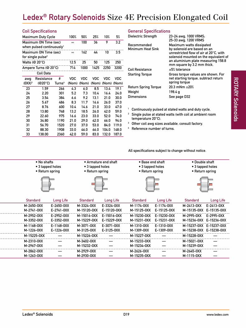
All specifications subject to change without notice.
General SpecificationsDielectric Strength 23-24 awg, 1000 VRMS;
25-33 awg, 1200 VRMSRecommended Maximum watts dissipatedMinimum Heat Sink by solenoid are based on an
unrestricted flow of air at 20°C, with solenoid mounted on the equivalent of an aluminium plate measuring 158.8 mm square by 3.2 mm thick.
Coil Resistance ±5% toleranceStarting Torque Gross torque values are shown. For
net starting torque, subtract return spring torque
Return Spring Torque 20.3 mNm ±20%Weight 198.4 gDimensions See page D32
• Armature cover • Armature cover • Armature cover • No shafts • Armature end shaft • Base end shaft • Double shaft • Armature end shaft • Base end shaft • Double shaft • 3 tapped holes • 3 tapped holes • 3 tapped holes • 3 tapped holes • Return spring • Return spring • Return spring • Return spring • Return spring • Return spring • Return spring
Stroke/ Nom. Axial Direction* Stroke Standard Long Life Standard Long Life Standard Long Life Standard Long Life Standard Long Life Standard Long Life Standard Long Life25° CW 0.9 mm M-3271-0XX E-3271-0XX M-3108-0XX E-3108-0XX M-15000-0XX E-15000-0XX M-2650-0XX E-2650-0XX M-3324-0XX E-3324-0XX M-1174-0XX E-1174-0XX M-2413-0XX E-2413-0XX 25° CCW 0.9 mm M-3258-0XX E-3258-0XX M-2975-0XX E-2975-0XX M-15001-0XX E-15001-0XX M-2741-0XX E-2741-0XX M-15120-0XX E-15120-0XX M-15125-0XX E-15125-0XX M-15135-0XX E-15135-0XX35° CW 0.9 mm M-15011-0XX E-15011-0XX M-1132-0XX E-1132-0XX M-3378-0XX E-3378-0XX M-2952-0XX E-2952-0XX M-15016-0XX E-15016-0XX M-15230-0XX E-15230-0XX M-2995-0XX E-2995-0XX 35° CCW 0.9 mm M-15015-0XX E-15015-0XX M-1258-0XX E-1258-0XX M-3379-0XX E-3379-0XX M-3352-0XX E-3352-0XX M-15229-0XX E-15229-0XX M-15231-0XX E-15231-0XX M-15236-0XX E-15236-0XX45° CW 0.9 mm M-1246-0XX E-1246-0XX M-3126-0XX E-3126-0XX M-2980-0XX E-2980-0XX M-1168-0XX E-1168-0XX M-3071-0XX E-3071-0XX M-1310-0XX E-1310-0XX M-15237-0XX E-15237-0XX 45° CCW 0.9 mm M-1247-0XX E-1247-0XX M-2900-0XX E-2900-0XX M-2893-0XX E-2893-0XX M-1226-0XX E-1226-0XX M-3125-0XX E-3125-0XX M-1309-0XX E-1309-0XX M-15238-0XX E-15238-0XX 55° CW 0.9 mm M-15222-0XX — M-15223-0XX — M-15224-0XX — M-15225-0XX — M-15226-0XX — M-15227-0XX — M-15228-0XX — 671⁄2° CW 1.1 mm M-15091-0XX — M-3074-0XX — M-3425-0XX — M-2310-0XX — M-3402-0XX — M-15233-0XX — M-15021-0XX — 671⁄2° CCW 1.1 mm M-1435-0XX — M-1521-0XX — M-15122-0XX — M-2967-0XX — M-15232-0XX — M-15234-0XX — M-15239-0XX — 95° CW 1.1 mm M-1218-0XX — M-3117-0XX — M-3084-0XX — M-2862-0XX — M-2929-0XX — M-2626-0XX — M-2645-0XX — 95° CCW 1.1 mm M-2563-0XX — M-2640-0XX — M-15127-0XX — M-1263-0XX — M-2930-0XX — M-15235-0XX — M-1115-0XX —
* Direction of rotation (cw – clockwise or ccw – counterclockwise) is viewed from the armature end of the solenoid opposite the mounting studs.
Note: The XX in the part number suffix must be filled in with the awg of your choice.
Coil SpecificationsMaximum Duty Cycle 100% 50% 25% 10% 5%Maximum ON Time (sec) ∞ 100 36 9 3.2 when pulsed continuously1
Maximum ON Time (sec) ∞ 162 44 10 3.5 for single pulse2
Watts (@ 20°C) 12.5 25 50 125 250Ampere Turns (@ 20°C) 714 1000 1425 2250 3200 Coil Data awg Resistance # VDC VDC VDC VDC VDC (0XX)3 (@20°C) Turns4 (Nom) (Nom) (Nom) (Nom) (Nom) 23 1.59 266 4.3 6.0 8.5 13.4 19.1 24 2.20 301 5.2 7.3 10.4 16.4 24.0 25 3.54 384 6.6 9.2 13.1 21.0 30.0 26 5.67 486 8.3 11.7 16.6 26.0 37.0 27 8.76 600 10.4 14.6 21.0 33.0 47.0 28 13.80 748 13.2 18.5 26.0 42.0 59.0 29 22.60 975 16.6 23.0 33.0 52.0 74.0 30 34.80 1190 21.0 29.0 42.0 66.0 94.0 31 56.70 1520 27.0 37.0 53.0 84.0 119.0 32 88.30 1908 33.0 46.0 66.0 104.0 148.0 33 138.00 2360 42.0 59.0 83.0 132.0 187.0
1 Continuously pulsed at stated watts and duty cycle.2 Single pulse at stated watts (with coil at ambient room
temperature 20°C).3 Other coil awg sizes available, consult factory.4 Reference number of turns.
Ledex® Rotary Solenoids Size 4E Precision Elongated Coil
Ledex® Solenoids www.ledex.comD20
ROT
ARY
Sol
enoi
ds
All catalogue products manufactured after April 1, 2006 are RoHS Compliant
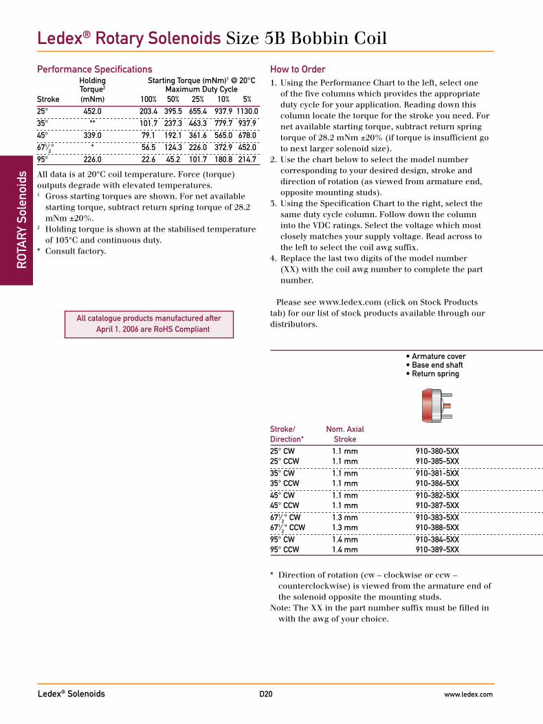
Ledex® Rotary Solenoids Size 5B Bobbin Coil
How to Order1. Using the Performance Chart to the left, select one
of the five columns which provides the appropriate duty cycle for your application. Reading down this column locate the torque for the stroke you need. For net available starting torque, subtract return spring torque of 28.2 mNm ±20% (if torque is insufficient go to next larger solenoid size).
2. Use the chart below to select the model number corresponding to your desired design, stroke and direction of rotation (as viewed from armature end, opposite mounting studs).
3. Using the Specification Chart to the right, select the same duty cycle column. Follow down the column into the VDC ratings. Select the voltage which most closely matches your supply voltage. Read across to the left to select the coil awg suffix.
4. Replace the last two digits of the model number (XX) with the coil awg number to complete the part number.
Please see www.ledex.com (click on Stock Products tab) for our list of stock products available through our distributors.
• Armature cover • No shafts • Armature end shaft • Base end shaft • Double shaft • Base end shaft • 3 tapped holes • 3 tapped holes • 3 tapped holes • 3 tapped holes • Return spring • Return spring • Return spring • Return spring • Return spring
Stroke/ Nom. Axial Direction* Stroke25° CW 1.1 mm 910-380-5XX 910-640-5XX 910-490-5XX 910-360-5XX 910-280-5XX 25° CCW 1.1 mm 910-385-5XX 910-645-5XX 910-495-5XX 910-365-5XX 910-285-5XX35° CW 1.1 mm 910-381-5XX 910-641-5XX 910-491-5XX 910-361-5XX 910-281-5XX 35° CCW 1.1 mm 910-386-5XX 910-646-5XX 910-496-5XX 910-366-5XX 910-286-5XX 45° CW 1.1 mm 910-382-5XX 910-642-5XX 910-492-5XX 910-362-5XX 910-282-5XX 45° CCW 1.1 mm 910-387-5XX 910-647-5XX 910-497-5XX 910-367-5XX 910-287-5XX671⁄2° CW 1.3 mm 910-383-5XX 910-643-5XX 910-493-5XX 910-363-5XX 910-283-5XX 671⁄2° CCW 1.3 mm 910-388-5XX 910-648-5XX 910-498-5XX 910-368-5XX 910-288-5XX 95° CW 1.4 mm 910-384-5XX 910-644-5XX 910-494-5XX 910-364-5XX 910-284-5XX 95° CCW 1.4 mm 910-389-5XX 910-649-5XX 910-499-5XX 910-369-5XX 910-289-5XX
Performance Specifications Holding Starting Torque (mNm)1 @ 20°C Torque2 Maximum Duty CycleStroke (mNm) 100% 50% 25% 10% 5%25° 452.0 203.4 395.5 655.4 937.9 1130.035° ** 101.7 237.3 463.3 779.7 937.945° 339.0 79.1 192.1 361.6 565.0 678.0671⁄2° * 56.5 124.3 226.0 372.9 452.095° 226.0 22.6 45.2 101.7 180.8 214.7
All data is at 20°C coil temperature. Force (torque) outputs degrade with elevated temperatures.1 Gross starting torques are shown. For net available
starting torque, subtract return spring torque of 28.2 mNm ±20%.
2 Holding torque is shown at the stabilised temperature of 105°C and continuous duty.
* Consult factory.
* Direction of rotation (cw – clockwise or ccw – counterclockwise) is viewed from the armature end of the solenoid opposite the mounting studs.
Note: The XX in the part number suffix must be filled in with the awg of your choice.
Ledex® Solenoids www.ledex.comD21
ROTA
RY Solenoids
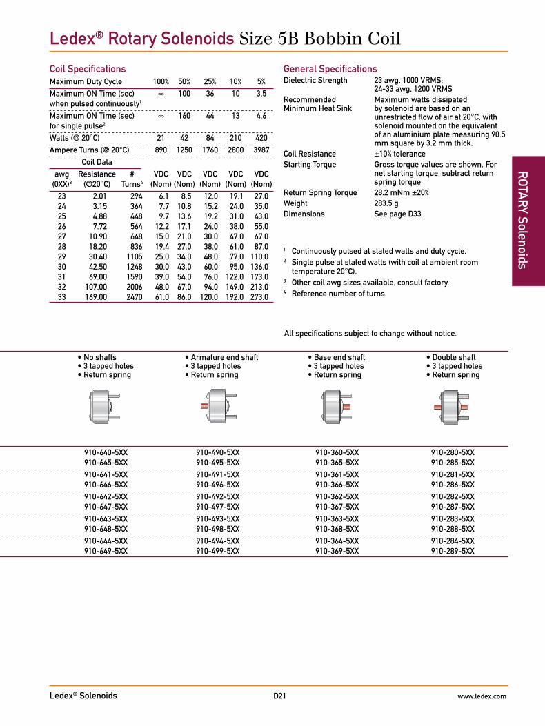
All specifications subject to change without notice.
General SpecificationsDielectric Strength 23 awg, 1000 VRMS;
24-33 awg, 1200 VRMSRecommended Maximum watts dissipatedMinimum Heat Sink by solenoid are based on an
unrestricted flow of air at 20°C, with solenoid mounted on the equivalent of an aluminium plate measuring 90.5 mm square by 3.2 mm thick.
Coil Resistance ±10% toleranceStarting Torque Gross torque values are shown. For
net starting torque, subtract return spring torque
Return Spring Torque 28.2 mNm ±20%Weight 283.5 gDimensions See page D33
Coil SpecificationsMaximum Duty Cycle 100% 50% 25% 10% 5%Maximum ON Time (sec) ∞ 100 36 10 3.5 when pulsed continuously1
Maximum ON Time (sec) ∞ 160 44 13 4.6 for single pulse2
Watts (@ 20°C) 21 42 84 210 420Ampere Turns (@ 20°C) 890 1250 1760 2800 3987 Coil Data awg Resistance # VDC VDC VDC VDC VDC (0XX)3 (@20°C) Turns4 (Nom) (Nom) (Nom) (Nom) (Nom) 23 2.01 294 6.1 8.5 12.0 19.1 27.0 24 3.15 364 7.7 10.8 15.2 24.0 35.0 25 4.88 448 9.7 13.6 19.2 31.0 43.0 26 7.72 564 12.2 17.1 24.0 38.0 55.0 27 10.90 648 15.0 21.0 30.0 47.0 67.0 28 18.20 836 19.4 27.0 38.0 61.0 87.0 29 30.40 1105 25.0 34.0 48.0 77.0 110.0 30 42.50 1248 30.0 43.0 60.0 95.0 136.0 31 69.00 1590 39.0 54.0 76.0 122.0 173.0 32 107.00 2006 48.0 67.0 94.0 149.0 213.0 33 169.00 2470 61.0 86.0 120.0 192.0 273.0
• Armature cover • No shafts • Armature end shaft • Base end shaft • Double shaft • Base end shaft • 3 tapped holes • 3 tapped holes • 3 tapped holes • 3 tapped holes • Return spring • Return spring • Return spring • Return spring • Return spring
Stroke/ Nom. Axial Direction* Stroke25° CW 1.1 mm 910-380-5XX 910-640-5XX 910-490-5XX 910-360-5XX 910-280-5XX 25° CCW 1.1 mm 910-385-5XX 910-645-5XX 910-495-5XX 910-365-5XX 910-285-5XX35° CW 1.1 mm 910-381-5XX 910-641-5XX 910-491-5XX 910-361-5XX 910-281-5XX 35° CCW 1.1 mm 910-386-5XX 910-646-5XX 910-496-5XX 910-366-5XX 910-286-5XX 45° CW 1.1 mm 910-382-5XX 910-642-5XX 910-492-5XX 910-362-5XX 910-282-5XX 45° CCW 1.1 mm 910-387-5XX 910-647-5XX 910-497-5XX 910-367-5XX 910-287-5XX671⁄2° CW 1.3 mm 910-383-5XX 910-643-5XX 910-493-5XX 910-363-5XX 910-283-5XX 671⁄2° CCW 1.3 mm 910-388-5XX 910-648-5XX 910-498-5XX 910-368-5XX 910-288-5XX 95° CW 1.4 mm 910-384-5XX 910-644-5XX 910-494-5XX 910-364-5XX 910-284-5XX 95° CCW 1.4 mm 910-389-5XX 910-649-5XX 910-499-5XX 910-369-5XX 910-289-5XX
1 Continuously pulsed at stated watts and duty cycle.2 Single pulse at stated watts (with coil at ambient room
temperature 20°C).3 Other coil awg sizes available, consult factory.4 Reference number of turns.
Ledex® Rotary Solenoids Size 5B Bobbin Coil
Ledex® Solenoids www.ledex.comD22
ROT
ARY
Sol
enoi
ds
All catalogue products manufactured after April 1, 2006 are RoHS Compliant
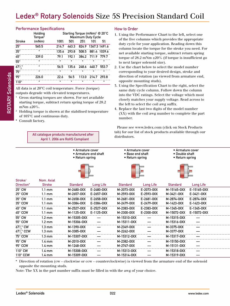
Ledex® Rotary Solenoids Size 5S Precision Standard Coil
Performance Specifications Holding Starting Torque (mNm)1 @ 20°C Torque2 Maximum Duty CycleStroke (mNm) 100% 50% 25% 10% 5%25° 565.5 214.7 463.3 824.9 1367.3 1491.635° * 135.6 293.8 508.5 881.4 1039.645° 339.0 79.1 192.1 384.2 711.9 779.755° * * * * * *671⁄2° * 56.5 135.6 248.6 440.7 553.775° * * * * * *95° 226.0 22.6 56.5 113.0 214.7 293.8110° * * * * * *
All data is at 20°C coil temperature. Force (torque) outputs degrade with elevated temperatures.1 Gross starting torques are shown. For net available
starting torque, subtract return spring torque of 28.2 mNm ±20%.
2 Holding torque is shown at the stabilised temperature of 105°C and continuous duty.
* Consult factory.
How to Order1. Using the Performance Chart to the left, select one
of the five columns which provides the appropriate duty cycle for your application. Reading down this column locate the torque for the stroke you need. For net available starting torque, subtract return spring torque of 28.2 mNm ±20% (if torque is insufficient go to next larger solenoid size).
2. Use the chart below to select the model number corresponding to your desired design, stroke and direction of rotation (as viewed from armature end, opposite mounting studs).
3. Using the Specification Chart to the right, select the same duty cycle column. Follow down the column into the VDC ratings. Select the voltage which most closely matches your supply voltage. Read across to the left to select the coil awg suffix.
4. Replace the last two digits of the model number (XX) with the coil awg number to complete the part number.
Please see www.ledex.com (click on Stock Products tab) for our list of stock products available through our distributors.
• Armature cover • Armature cover • Armature cover • No shafts • Armature end shaft • Base end shaft • Double shaft • Armature end shaft • Base end shaft • Double shaft • 3 tapped holes • 3 tapped holes • 3 tapped holes • 3 tapped holes • Return spring • Return spring • Return spring • Return spring • Return spring • Return spring • Return spring
Stroke/ Nom. Axial Direction* Stroke Standard Long Life Standard Long Life Standard Long Life Standard Long Life Standard Long Life Standard Long Life Standard Long Life25° CW 1.1 mm M-2480-0XX E-2480-0XX M-2073-0XX E-2073-0XX M-15165-0XX E-15165-0XX M-1082-0XX E-1082-0XX M-2668-0XX E-2668-0XX M-2050-0XX E-2050-0XX M-2414-0XX E-2414-0XX 25° CCW 1.1 mm M-2657-0XX E-2657-0XX M-2593-0XX E-2593-0XX M-3421-0XX E-3421-0XX M-2434-0XX E-2434-0XX M-2669-0XX E-2669-0XX M-3189-0XX E-3189-0XX M-2708-0XX E-2708-0XX35° CW 1.1 mm M-2658-0XX E-2658-0XX M-2681-0XX E-2681-0XX M-2874-0XX E-2874-0XX M-2560-0XX E-2560-0XX M-3151-0XX E-3151-0XX M-2186-0XX E-2186-0XX M-2875-0XX E-2875-0XX 35° CCW 1.1 mm M-3384-0XX E-3384-0XX M-2479-0XX E-2479-0XX M-1423-0XX E-1423-0XX M-1087-0XX E-1087-0XX M-1431-0XX E-1431-0XX M-3276-0XX E-3276-0XX M-2016-0XX E-2016-0XX45° CW 1.1 mm M-2527-0XX E-2527-0XX M-2383-0XX E-2383-0XX M-1345-0XX E-1345-0XX M-2397-0XX E-2397-0XX M-2555-0XX E-2555-0XX M-2136-0XX E-2136-0XX M-3397-0XX E-3397-0XX 45° CCW 1.1 mm M-1125-0XX E-1125-0XX M-2300-0XX E-2300-0XX M-15072-0XX E-15072-0XX M-2185-0XX E-2185-0XX M-3238-0XX E-3238-0XX M-1308-0XX E-1308-0XX M-2845-0XX E-2845-0XX55° CW 1.2 mm M-15305-0XX — M-15310-0XX — M-15315-0XX — M-15320-0XX — M-15325-0XX — M-15330-0XX — M-15335-0XX — 55° CCW 1.2 mm M-15306-0XX — M-15311-0XX — M-15316-0XX — M-15321-0XX — M-15326-0XX — M-15331-0XX — M-15336-0XX —671⁄2° CW 1.3 mm M-1390-0XX — M-2349-0XX — M-3375-0XX — M-2522-0XX — M-2075-0XX — M-1020-0XX — M-3399-0XX — 671⁄2° CCW 1.3 mm M-3385-0XX — M-2262-0XX — M-3377-0XX — M-2902-0XX — M-3249-0XX — M-15055-0XX — M-3400-0XX —75° CCW 1.3 mm M-15307-0XX — M-15312-0XX — M-15317-0XX — M-15322-0XX — M-15327-0XX — M-15332-0XX — M-15337-0XX —95° CW 1.4 mm M-2010-0XX — M-2382-0XX — M-15150-0XX — M-2714-0XX — M-2074-0XX — M-2957-0XX — M-1155-0XX — 95° CCW 1.4 mm M-1248-0XX — M-2747-0XX — M-15131-0XX — M-2296-0XX — M-2150-0XX — M-1307-0XX — M-1154-0XX —110° CW 1.4 mm M-15308-0XX — M-15313-0XX — M-15318-0XX — M-15323-0XX — M-15328-0XX — M-15333-0XX — M-15338-0XX — 110° CCW 1.4 mm M-15309-0XX — M-15314-0XX — M-15319-0XX — M-15324-0XX — M-15329-0XX — M-15334-0XX — M-15339-0XX —
* Direction of rotation (cw – clockwise or ccw – counterclockwise) is viewed from the armature end of the solenoid opposite the mounting studs.
Note: The XX in the part number suffix must be filled in with the awg of your choice.
Ledex® Solenoids www.ledex.comD23
ROTA
RY Solenoids
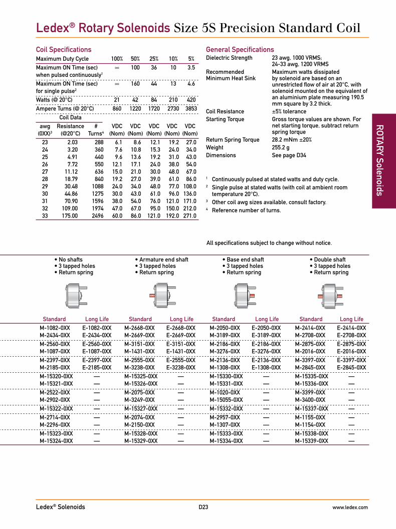
All specifications subject to change without notice.
Coil SpecificationsMaximum Duty Cycle 100% 50% 25% 10% 5%Maximum ON Time (sec) ∞ 100 36 10 3.5 when pulsed continuously1
Maximum ON Time (sec) ∞ 160 44 13 4.6 for single pulse2
Watts (@ 20°C) 21 42 84 210 420Ampere Turns (@ 20°C) 860 1220 1720 2730 3853 Coil Data awg Resistance # VDC VDC VDC VDC VDC (0XX)3 (@20°C) Turns4 (Nom) (Nom) (Nom) (Nom) (Nom) 23 2.03 288 6.1 8.6 12.1 19.2 27.0 24 3.20 360 7.6 10.8 15.3 24.0 34.0 25 4.91 440 9.6 13.6 19.2 31.0 43.0 26 7.72 550 12.1 17.1 24.0 38.0 54.0 27 11.12 636 15.0 21.0 30.0 48.0 67.0 28 18.79 840 19.2 27.0 39.0 61.0 86.0 29 30.48 1088 24.0 34.0 48.0 77.0 108.0 30 44.86 1275 30.0 43.0 61.0 96.0 136.0 31 70.90 1596 38.0 54.0 76.0 121.0 171.0 32 109.00 1974 47.0 67.0 95.0 150.0 212.0 33 175.00 2496 60.0 86.0 121.0 192.0 271.0
General SpecificationsDielectric Strength 23 awg, 1000 VRMS;
24-33 awg, 1200 VRMSRecommended Maximum watts dissipatedMinimum Heat Sink by solenoid are based on an
unrestricted flow of air at 20°C, with solenoid mounted on the equivalent of an aluminium plate measuring 190.5 mm square by 3.2 thick.
Coil Resistance ±5% toleranceStarting Torque Gross torque values are shown. For
net starting torque, subtract return spring torque
Return Spring Torque 28.2 mNm ±20%Weight 255.2 gDimensions See page D34
1 Continuously pulsed at stated watts and duty cycle.2 Single pulse at stated watts (with coil at ambient room
temperature 20°C).3 Other coil awg sizes available, consult factory.4 Reference number of turns.
• Armature cover • Armature cover • Armature cover • No shafts • Armature end shaft • Base end shaft • Double shaft • Armature end shaft • Base end shaft • Double shaft • 3 tapped holes • 3 tapped holes • 3 tapped holes • 3 tapped holes • Return spring • Return spring • Return spring • Return spring • Return spring • Return spring • Return spring
Stroke/ Nom. Axial Direction* Stroke Standard Long Life Standard Long Life Standard Long Life Standard Long Life Standard Long Life Standard Long Life Standard Long Life25° CW 1.1 mm M-2480-0XX E-2480-0XX M-2073-0XX E-2073-0XX M-15165-0XX E-15165-0XX M-1082-0XX E-1082-0XX M-2668-0XX E-2668-0XX M-2050-0XX E-2050-0XX M-2414-0XX E-2414-0XX 25° CCW 1.1 mm M-2657-0XX E-2657-0XX M-2593-0XX E-2593-0XX M-3421-0XX E-3421-0XX M-2434-0XX E-2434-0XX M-2669-0XX E-2669-0XX M-3189-0XX E-3189-0XX M-2708-0XX E-2708-0XX35° CW 1.1 mm M-2658-0XX E-2658-0XX M-2681-0XX E-2681-0XX M-2874-0XX E-2874-0XX M-2560-0XX E-2560-0XX M-3151-0XX E-3151-0XX M-2186-0XX E-2186-0XX M-2875-0XX E-2875-0XX 35° CCW 1.1 mm M-3384-0XX E-3384-0XX M-2479-0XX E-2479-0XX M-1423-0XX E-1423-0XX M-1087-0XX E-1087-0XX M-1431-0XX E-1431-0XX M-3276-0XX E-3276-0XX M-2016-0XX E-2016-0XX45° CW 1.1 mm M-2527-0XX E-2527-0XX M-2383-0XX E-2383-0XX M-1345-0XX E-1345-0XX M-2397-0XX E-2397-0XX M-2555-0XX E-2555-0XX M-2136-0XX E-2136-0XX M-3397-0XX E-3397-0XX 45° CCW 1.1 mm M-1125-0XX E-1125-0XX M-2300-0XX E-2300-0XX M-15072-0XX E-15072-0XX M-2185-0XX E-2185-0XX M-3238-0XX E-3238-0XX M-1308-0XX E-1308-0XX M-2845-0XX E-2845-0XX55° CW 1.2 mm M-15305-0XX — M-15310-0XX — M-15315-0XX — M-15320-0XX — M-15325-0XX — M-15330-0XX — M-15335-0XX — 55° CCW 1.2 mm M-15306-0XX — M-15311-0XX — M-15316-0XX — M-15321-0XX — M-15326-0XX — M-15331-0XX — M-15336-0XX —671⁄2° CW 1.3 mm M-1390-0XX — M-2349-0XX — M-3375-0XX — M-2522-0XX — M-2075-0XX — M-1020-0XX — M-3399-0XX — 671⁄2° CCW 1.3 mm M-3385-0XX — M-2262-0XX — M-3377-0XX — M-2902-0XX — M-3249-0XX — M-15055-0XX — M-3400-0XX —75° CCW 1.3 mm M-15307-0XX — M-15312-0XX — M-15317-0XX — M-15322-0XX — M-15327-0XX — M-15332-0XX — M-15337-0XX —95° CW 1.4 mm M-2010-0XX — M-2382-0XX — M-15150-0XX — M-2714-0XX — M-2074-0XX — M-2957-0XX — M-1155-0XX — 95° CCW 1.4 mm M-1248-0XX — M-2747-0XX — M-15131-0XX — M-2296-0XX — M-2150-0XX — M-1307-0XX — M-1154-0XX —110° CW 1.4 mm M-15308-0XX — M-15313-0XX — M-15318-0XX — M-15323-0XX — M-15328-0XX — M-15333-0XX — M-15338-0XX — 110° CCW 1.4 mm M-15309-0XX — M-15314-0XX — M-15319-0XX — M-15324-0XX — M-15329-0XX — M-15334-0XX — M-15339-0XX —
* Direction of rotation (cw – clockwise or ccw – counterclockwise) is viewed from the armature end of the solenoid opposite the mounting studs.
Note: The XX in the part number suffix must be filled in with the awg of your choice.
Ledex® Rotary Solenoids Size 5S Precision Standard Coil
Ledex® Solenoids www.ledex.comD24
ROT
ARY
Sol
enoi
ds
All catalogue products manufactured after April 1, 2006 are RoHS Compliant
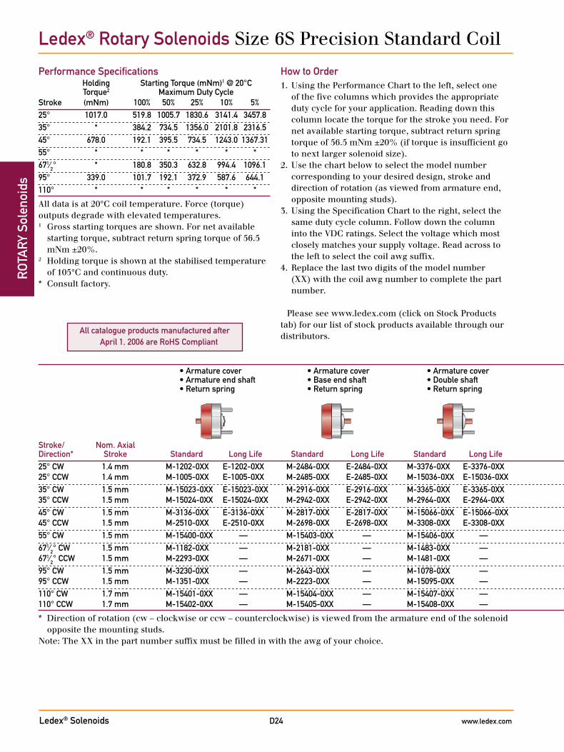
Ledex® Rotary Solenoids Size 6S Precision Standard Coil
Performance Specifications Holding Starting Torque (mNm)1 @ 20°C Torque2 Maximum Duty CycleStroke (mNm) 100% 50% 25% 10% 5%25° 1017.0 519.8 1005.7 1830.6 3141.4 3457.835° * 384.2 734.5 1356.0 2101.8 2316.545° 678.0 192.1 395.5 734.5 1243.0 1367.3155° * * * * * *671⁄2° * 180.8 350.3 632.8 994.4 1096.195° 339.0 101.7 192.1 372.9 587.6 644.1110° * * * * * *
All data is at 20°C coil temperature. Force (torque) outputs degrade with elevated temperatures.1 Gross starting torques are shown. For net available
starting torque, subtract return spring torque of 56.5 mNm ±20%.
2 Holding torque is shown at the stabilised temperature of 105°C and continuous duty.
* Consult factory.
How to Order1. Using the Performance Chart to the left, select one
of the five columns which provides the appropriate duty cycle for your application. Reading down this column locate the torque for the stroke you need. For net available starting torque, subtract return spring torque of 56.5 mNm ±20% (if torque is insufficient go to next larger solenoid size).
2. Use the chart below to select the model number corresponding to your desired design, stroke and direction of rotation (as viewed from armature end, opposite mounting studs).
3. Using the Specification Chart to the right, select the same duty cycle column. Follow down the column into the VDC ratings. Select the voltage which most closely matches your supply voltage. Read across to the left to select the coil awg suffix.
4. Replace the last two digits of the model number (XX) with the coil awg number to complete the part number.
Please see www.ledex.com (click on Stock Products tab) for our list of stock products available through our distributors.
• Armature cover • Armature cover • Armature cover • No shafts • Armature end shaft • Base end shaft • Double shaft • Armature end shaft • Base end shaft • Double shaft • 3 tapped holes • 3 tapped holes • 3 tapped holes • 3 tapped holes • Return spring • Return spring • Return spring • Return spring • Return spring • Return spring • Return spring
Stroke/ Nom. Axial Direction* Stroke Standard Long Life Standard Long Life Standard Long Life Standard Long Life Standard Long Life Standard Long Life Standard Long Life25° CW 1.4 mm M-1202-0XX E-1202-0XX M-2484-0XX E-2484-0XX M-3376-0XX E-3376-0XX M-2481-0XX E-2481-0XX M-3055-0XX E-3055-0XX M-2184-0XX E-2184-0XX M-15067-0XX E-15067-0XX 25° CCW 1.4 mm M-1005-0XX E-1005-0XX M-2485-0XX E-2485-0XX M-15036-0XX E-15036-0XX M-1002-0XX E-1002-0XX M-1291-0XX E-1291-0XX M-1306-0XX E-1306-0XX M-15123-0XX E-15123-0XX35° CW 1.5 mm M-15023-0XX E-15023-0XX M-2916-0XX E-2916-0XX M-3365-0XX E-3365-0XX M-2861-0XX E-2861-0XX M-1230-0XX E-1230-0XX M-15417-0XX E-15417-0XX M-2057-0XX E-2057-0XX 35° CCW 1.5 mm M-15024-0XX E-15024-0XX M-2942-0XX E-2942-0XX M-2964-0XX E-2964-0XX M-2269-0XX E-2269-0XX M-15412-0XX E-15412-0XX M-15418-0XX E-15418-0XX M-15136-0XX E-15136-0XX45° CW 1.5 mm M-3136-0XX E-3136-0XX M-2817-0XX E-2817-0XX M-15066-0XX E-15066-0XX M-1112-0XX E-1112-0XX M-15013-0XX E-15013-0XX M-1311-0XX E-1311-0XX M-15064-0XX E-15064-0XX 45° CCW 1.5 mm M-2510-0XX E-2510-0XX M-2698-0XX E-2698-0XX M-3308-0XX E-3308-0XX M-2328-0XX E-2328-0XX M-3208-0XX E-3208-0XX M-1286-0XX E-1286-0XX M-15424-0XX E-15424-0XX55° CW 1.5 mm M-15400-0XX — M-15403-0XX — M-15406-0XX — M-15409-0XX — M-15413-0XX — M-15419-0XX — M-15425-0XX — 671⁄2° CW 1.5 mm M-1182-0XX — M-2181-0XX — M-1483-0XX — M-2404-0XX — M-3264-0XX — M-15420-0XX — M-15426-0XX — 671⁄2° CCW 1.5 mm M-2293-0XX — M-2671-0XX — M-1481-0XX — M-2661-0XX — M-15414-0XX — M-15421-0XX — M-15427-0XX — 95° CW 1.5 mm M-3230-0XX — M-2643-0XX — M-1078-0XX — M-2072-0XX — M-2826-0XX — M-1313-0XX — M-2001-0XX — 95° CCW 1.5 mm M-1351-0XX — M-2223-0XX — M-15095-0XX — M-2071-0XX — M-3002-0XX — M-2936-0XX — M-15030-0XX — 110° CW 1.7 mm M-15401-0XX — M-15404-0XX — M-15407-0XX — M-15410-0XX — M-15415-0XX — M-15422-0XX — M-15428-0XX — 110° CCW 1.7 mm M-15402-0XX — M-15405-0XX — M-15408-0XX — M-15411-0XX — M-15416-0XX — M-15423-0XX — M-15429-0XX —
* Direction of rotation (cw – clockwise or ccw – counterclockwise) is viewed from the armature end of the solenoid opposite the mounting studs.
Note: The XX in the part number suffix must be filled in with the awg of your choice.

Ledex® Solenoids www.ledex.comD25
ROTA
RY Solenoids
All specifications subject to change without notice.
General SpecificationsDielectric Strength 23-31 awg, 1200 VRMS;
32-33 awg, 1500 VRMSRecommended Maximum watts dissipatedMinimum Heat Sink by solenoid are based on an
unrestricted flow of air at 20°C, with solenoid mounted on the equivalent of an aluminium plate measuring 314.5 mm square by 3.2 thick.
Coil Resistance ±5% toleranceStarting Torque Gross torque values are shown. For
net starting torque, subtract return spring torque
Return Spring Torque 56.5 mNm ±20%Weight 510.3 gDimensions See page D35
Coil SpecificationsMaximum Duty Cycle 100% 50% 25% 10% 5%Maximum ON Time (sec) ∞ 87 36 13 4.6 when pulsed continuously1
Maximum ON Time (sec) ∞ 140 44 16 5.7 for single pulse2
Watts (@ 20°C) 32 64 128 320 640Ampere Turns (@ 20°C) 1240 1760 2490 3920 5555 Coil Data awg Resistance # VDC VDC VDC VDC VDC (0XX)3 (@20°C) Turns4 (Nom) (Nom) (Nom) (Nom) (Nom) 23 3.59 432 10.3 14.6 21.0 33.0 46.0 24 5.24 500 13.0 18.4 26.0 41.0 58.0 25 9.51 708 16.7 24.0 33.0 53.0 75.0 26 14.44 858 21.0 30.0 42.0 66.0 94.0 27 23.69 1110 27.0 38.0 53.0 84.0 119.0 28 38.27 1411 34.0 48.0 68.0 106.0 151.0 29 54.62 1638 41.0 59.0 83.0 131.0 185.0 30 93.67 2184 53.0 76.0 107.0 168.0 238.0 31 143.00 2645 67.0 95.0 134.0 211.0 299.0 32 223.00 3328 83.0 118.0 167.0 262.0 372.0 33 338.00 4004 105.0 149.0 210.0 331.0 469.0
• Armature cover • Armature cover • Armature cover • No shafts • Armature end shaft • Base end shaft • Double shaft • Armature end shaft • Base end shaft • Double shaft • 3 tapped holes • 3 tapped holes • 3 tapped holes • 3 tapped holes • Return spring • Return spring • Return spring • Return spring • Return spring • Return spring • Return spring
Stroke/ Nom. Axial Direction* Stroke Standard Long Life Standard Long Life Standard Long Life Standard Long Life Standard Long Life Standard Long Life Standard Long Life25° CW 1.4 mm M-1202-0XX E-1202-0XX M-2484-0XX E-2484-0XX M-3376-0XX E-3376-0XX M-2481-0XX E-2481-0XX M-3055-0XX E-3055-0XX M-2184-0XX E-2184-0XX M-15067-0XX E-15067-0XX 25° CCW 1.4 mm M-1005-0XX E-1005-0XX M-2485-0XX E-2485-0XX M-15036-0XX E-15036-0XX M-1002-0XX E-1002-0XX M-1291-0XX E-1291-0XX M-1306-0XX E-1306-0XX M-15123-0XX E-15123-0XX35° CW 1.5 mm M-15023-0XX E-15023-0XX M-2916-0XX E-2916-0XX M-3365-0XX E-3365-0XX M-2861-0XX E-2861-0XX M-1230-0XX E-1230-0XX M-15417-0XX E-15417-0XX M-2057-0XX E-2057-0XX 35° CCW 1.5 mm M-15024-0XX E-15024-0XX M-2942-0XX E-2942-0XX M-2964-0XX E-2964-0XX M-2269-0XX E-2269-0XX M-15412-0XX E-15412-0XX M-15418-0XX E-15418-0XX M-15136-0XX E-15136-0XX45° CW 1.5 mm M-3136-0XX E-3136-0XX M-2817-0XX E-2817-0XX M-15066-0XX E-15066-0XX M-1112-0XX E-1112-0XX M-15013-0XX E-15013-0XX M-1311-0XX E-1311-0XX M-15064-0XX E-15064-0XX 45° CCW 1.5 mm M-2510-0XX E-2510-0XX M-2698-0XX E-2698-0XX M-3308-0XX E-3308-0XX M-2328-0XX E-2328-0XX M-3208-0XX E-3208-0XX M-1286-0XX E-1286-0XX M-15424-0XX E-15424-0XX55° CW 1.5 mm M-15400-0XX — M-15403-0XX — M-15406-0XX — M-15409-0XX — M-15413-0XX — M-15419-0XX — M-15425-0XX — 671⁄2° CW 1.5 mm M-1182-0XX — M-2181-0XX — M-1483-0XX — M-2404-0XX — M-3264-0XX — M-15420-0XX — M-15426-0XX — 671⁄2° CCW 1.5 mm M-2293-0XX — M-2671-0XX — M-1481-0XX — M-2661-0XX — M-15414-0XX — M-15421-0XX — M-15427-0XX — 95° CW 1.5 mm M-3230-0XX — M-2643-0XX — M-1078-0XX — M-2072-0XX — M-2826-0XX — M-1313-0XX — M-2001-0XX — 95° CCW 1.5 mm M-1351-0XX — M-2223-0XX — M-15095-0XX — M-2071-0XX — M-3002-0XX — M-2936-0XX — M-15030-0XX — 110° CW 1.7 mm M-15401-0XX — M-15404-0XX — M-15407-0XX — M-15410-0XX — M-15415-0XX — M-15422-0XX — M-15428-0XX — 110° CCW 1.7 mm M-15402-0XX — M-15405-0XX — M-15408-0XX — M-15411-0XX — M-15416-0XX — M-15423-0XX — M-15429-0XX —
* Direction of rotation (cw – clockwise or ccw – counterclockwise) is viewed from the armature end of the solenoid opposite the mounting studs.
Note: The XX in the part number suffix must be filled in with the awg of your choice.
1 Continuously pulsed at stated watts and duty cycle.2 Single pulse at stated watts (with coil at ambient room
temperature 20°C).3 Other coil awg sizes available, consult factory.4 Reference number of turns.
Ledex® Rotary Solenoids Size 6S Precision Standard Coil
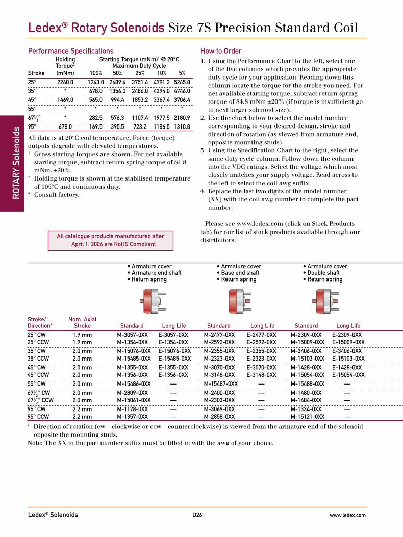
Ledex® Solenoids www.ledex.comD26
ROT
ARY
Sol
enoi
ds
All catalogue products manufactured after April 1, 2006 are RoHS Compliant
Ledex® Rotary Solenoids Size 7S Precision Standard Coil
Performance Specifications Holding Starting Torque (mNm)1 @ 20°C Torque2 Maximum Duty CycleStroke (mNm) 100% 50% 25% 10% 5%25° 2260.0 1243.0 2689.4 3751.6 4791.2 5265.835° * 678.0 1356.0 2486.0 4294.0 4746.045° 1469.0 565.0 994.4 1853.2 3367.4 3706.455° * * * * * *671⁄2° * 282.5 576.3 1107.4 1977.5 2180.995° 678.0 169.5 395.5 723.2 1186.5 1310.8
All data is at 20°C coil temperature. Force (torque) outputs degrade with elevated temperatures.1 Gross starting torques are shown. For net available
starting torque, subtract return spring torque of 84.8 mNm. ±20%.
2 Holding torque is shown at the stabilised temperature of 105°C and continuous duty.
* Consult factory.
How to Order1. Using the Performance Chart to the left, select one
of the five columns which provides the appropriate duty cycle for your application. Reading down this column locate the torque for the stroke you need. For net available starting torque, subtract return spring torque of 84.8 mNm ±20% (if torque is insufficient go to next larger solenoid size).
2. Use the chart below to select the model number corresponding to your desired design, stroke and direction of rotation (as viewed from armature end, opposite mounting studs).
3. Using the Specification Chart to the right, select the same duty cycle column. Follow down the column into the VDC ratings. Select the voltage which most closely matches your supply voltage. Read across to the left to select the coil awg suffix.
4. Replace the last two digits of the model number (XX) with the coil awg number to complete the part number.
Please see www.ledex.com (click on Stock Products tab) for our list of stock products available through our distributors.
• Armature cover • Armature cover • Armature cover • No shafts • Armature end shaft • Base end shaft • Double shaft • Armature end shaft • Base end shaft • Double shaft • 3 tapped holes • 3 tapped holes • 3 tapped holes • 3 tapped holes • Return spring • Return spring • Return spring • Return spring • Return spring • Return spring • Return spring
Stroke/ Nom. Axial Direction* Stroke Standard Long Life Standard Long Life Standard Long Life Standard Long Life Standard Long Life Standard Long Life Standard Long Life25° CW 1.9 mm M-3057-0XX E-3057-0XX M-2477-0XX E-2477-0XX M-2309-0XX E-2309-0XX M-1352-0XX E-1352-0XX M-15491-0XX E-15491-0XX M-2490-0XX E-2490-0XX M-2415-0XX E-2415-0XX 25° CCW 1.9 mm M-1354-0XX E-1354-0XX M-2592-0XX E-2592-0XX M-15009-0XX E-15009-0XX M-2590-0XX E-2590-0XX M-1197-0XX E-1197-0XX M-3362-0XX E-3362-0XX M-15116-0XX E-15116-0XX35° CW 2.0 mm M-15076-0XX E-15076-0XX M-2355-0XX E-2355-0XX M-3406-0XX E-3406-0XX M-2388-0XX E-2388-0XX M-15492-0XX E-15492-0XX M-15498-0XX E-15498-0XX M-15134-0XX E-15134-0XX 35° CCW 2.0 mm M-15485-0XX E-15485-0XX M-2323-0XX E-2323-0XX M-15103-0XX E-15103-0XX M-15616-0XX E-15616-0XX M-15493-0XX E-15493-0XX M-1467-0XX E-1467-0XX M-15137-0XX E-15137-0XX45° CW 2.0 mm M-1355-0XX E-1355-0XX M-3070-0XX E-3070-0XX M-1428-0XX E-1428-0XX M-2950-0XX E-2950-0XX M-3007-0XX E-3007-0XX M-1312-0XX E-1312-0XX M-15502-0XX E-15502-0XX 45° CCW 2.0 mm M-1356-0XX E-1356-0XX M-3148-0XX E-3148-0XX M-15054-0XX E-15054-0XX M-3096-0XX E-3096-0XX M-15014-0XX E-15014-0XX M-1317-0XX E-1317-0XX M-15503-0XX E-15503-0XX55° CW 2.0 mm M-15486-0XX — M-15487-0XX — M-15488-0XX — M-15490-0XX — M-15494-0XX — M-15499-0XX — M-15614-0XX — 671⁄2° CW 2.0 mm M-2809-0XX — M-2400-0XX — M-1480-0XX — M-3350-0XX — M-15495-0XX — M-15500-0XX — M-15504-0XX — 671⁄2° CCW 2.0 mm M-15061-0XX — M-2303-0XX — M-1484-0XX — M-15158-0XX — M-15496-0XX — M-15501-0XX — M-15505-0XX — 95° CW 2.2 mm M-1178-0XX — M-3069-0XX — M-1334-0XX — M-1353-0XX — M-15104-0XX — M-2869-0XX — M-3037-0XX — 95° CCW 2.2 mm M-1357-0XX — M-2858-0XX — M-15121-0XX — M-3289-0XX — M-15497-0XX — M-1316-0XX — M-15506-0XX —
* Direction of rotation (cw – clockwise or ccw – counterclockwise) is viewed from the armature end of the solenoid opposite the mounting studs.
Note: The XX in the part number suffix must be filled in with the awg of your choice.
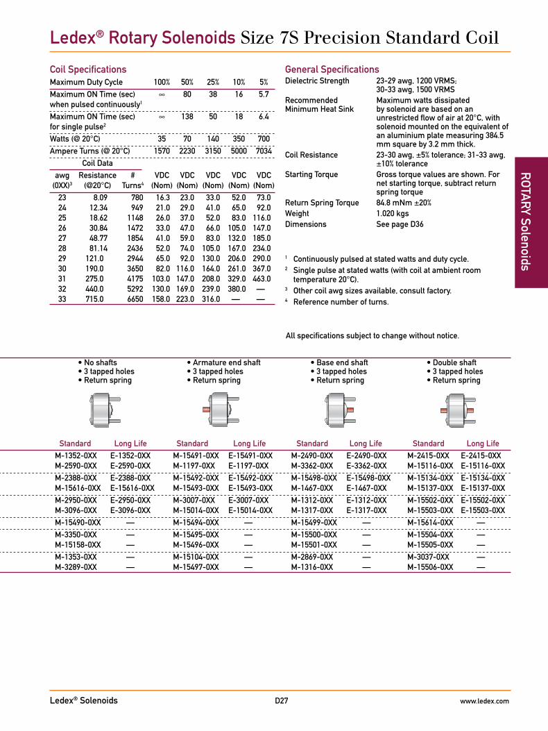
Ledex® Solenoids www.ledex.comD27
ROTA
RY Solenoids
All specifications subject to change without notice.
Coil SpecificationsMaximum Duty Cycle 100% 50% 25% 10% 5%Maximum ON Time (sec) ∞ 80 38 16 5.7 when pulsed continuously1
Maximum ON Time (sec) ∞ 138 50 18 6.4 for single pulse2
Watts (@ 20°C) 35 70 140 350 700Ampere Turns (@ 20°C) 1570 2230 3150 5000 7034 Coil Data awg Resistance # VDC VDC VDC VDC VDC (0XX)3 (@20°C) Turns4 (Nom) (Nom) (Nom) (Nom) (Nom) 23 8.09 780 16.3 23.0 33.0 52.0 73.0 24 12.34 949 21.0 29.0 41.0 65.0 92.0 25 18.62 1148 26.0 37.0 52.0 83.0 116.0 26 30.84 1472 33.0 47.0 66.0 105.0 147.0 27 48.77 1854 41.0 59.0 83.0 132.0 185.0 28 81.14 2436 52.0 74.0 105.0 167.0 234.0 29 121.0 2944 65.0 92.0 130.0 206.0 290.0 30 190.0 3650 82.0 116.0 164.0 261.0 367.0 31 275.0 4175 103.0 147.0 208.0 329.0 463.0 32 440.0 5292 130.0 169.0 239.0 380.0 — 33 715.0 6650 158.0 223.0 316.0 — —
General SpecificationsDielectric Strength 23-29 awg, 1200 VRMS;
30-33 awg, 1500 VRMSRecommended Maximum watts dissipatedMinimum Heat Sink by solenoid are based on an
unrestricted flow of air at 20°C, with solenoid mounted on the equivalent of an aluminium plate measuring 384.5 mm square by 3.2 mm thick.
Coil Resistance 23-30 awg, ±5% tolerance; 31-33 awg, ±10% tolerance
Starting Torque Gross torque values are shown. For net starting torque, subtract return spring torque
Return Spring Torque 84.8 mNm ±20%Weight 1.020 kgsDimensions See page D36
• Armature cover • Armature cover • Armature cover • No shafts • Armature end shaft • Base end shaft • Double shaft • Armature end shaft • Base end shaft • Double shaft • 3 tapped holes • 3 tapped holes • 3 tapped holes • 3 tapped holes • Return spring • Return spring • Return spring • Return spring • Return spring • Return spring • Return spring
Stroke/ Nom. Axial Direction* Stroke Standard Long Life Standard Long Life Standard Long Life Standard Long Life Standard Long Life Standard Long Life Standard Long Life25° CW 1.9 mm M-3057-0XX E-3057-0XX M-2477-0XX E-2477-0XX M-2309-0XX E-2309-0XX M-1352-0XX E-1352-0XX M-15491-0XX E-15491-0XX M-2490-0XX E-2490-0XX M-2415-0XX E-2415-0XX 25° CCW 1.9 mm M-1354-0XX E-1354-0XX M-2592-0XX E-2592-0XX M-15009-0XX E-15009-0XX M-2590-0XX E-2590-0XX M-1197-0XX E-1197-0XX M-3362-0XX E-3362-0XX M-15116-0XX E-15116-0XX35° CW 2.0 mm M-15076-0XX E-15076-0XX M-2355-0XX E-2355-0XX M-3406-0XX E-3406-0XX M-2388-0XX E-2388-0XX M-15492-0XX E-15492-0XX M-15498-0XX E-15498-0XX M-15134-0XX E-15134-0XX 35° CCW 2.0 mm M-15485-0XX E-15485-0XX M-2323-0XX E-2323-0XX M-15103-0XX E-15103-0XX M-15616-0XX E-15616-0XX M-15493-0XX E-15493-0XX M-1467-0XX E-1467-0XX M-15137-0XX E-15137-0XX45° CW 2.0 mm M-1355-0XX E-1355-0XX M-3070-0XX E-3070-0XX M-1428-0XX E-1428-0XX M-2950-0XX E-2950-0XX M-3007-0XX E-3007-0XX M-1312-0XX E-1312-0XX M-15502-0XX E-15502-0XX 45° CCW 2.0 mm M-1356-0XX E-1356-0XX M-3148-0XX E-3148-0XX M-15054-0XX E-15054-0XX M-3096-0XX E-3096-0XX M-15014-0XX E-15014-0XX M-1317-0XX E-1317-0XX M-15503-0XX E-15503-0XX55° CW 2.0 mm M-15486-0XX — M-15487-0XX — M-15488-0XX — M-15490-0XX — M-15494-0XX — M-15499-0XX — M-15614-0XX — 671⁄2° CW 2.0 mm M-2809-0XX — M-2400-0XX — M-1480-0XX — M-3350-0XX — M-15495-0XX — M-15500-0XX — M-15504-0XX — 671⁄2° CCW 2.0 mm M-15061-0XX — M-2303-0XX — M-1484-0XX — M-15158-0XX — M-15496-0XX — M-15501-0XX — M-15505-0XX — 95° CW 2.2 mm M-1178-0XX — M-3069-0XX — M-1334-0XX — M-1353-0XX — M-15104-0XX — M-2869-0XX — M-3037-0XX — 95° CCW 2.2 mm M-1357-0XX — M-2858-0XX — M-15121-0XX — M-3289-0XX — M-15497-0XX — M-1316-0XX — M-15506-0XX —
* Direction of rotation (cw – clockwise or ccw – counterclockwise) is viewed from the armature end of the solenoid opposite the mounting studs.
Note: The XX in the part number suffix must be filled in with the awg of your choice.
1 Continuously pulsed at stated watts and duty cycle.2 Single pulse at stated watts (with coil at ambient room
temperature 20°C).3 Other coil awg sizes available, consult factory.4 Reference number of turns.
Ledex® Rotary Solenoids Size 7S Precision Standard Coil

Ledex® Solenoids www.ledex.comD28
ROT
ARY
Sol
enoi
dsLedex® Rotary Solenoids 1E Dimensions
Notes:
1) All configurations have 250 mm minimum leads, 24 awg, PVC insulation.
2) For electrical specs and performance charts, see pages D10-D11.
mm
Armature Cover Configuration — Armature End Shaft Armature Cover Configuration — Base End Shaft
Armature Cover Configuration — Double Shaft
Double ShaftArmature End Shaft
No Shaft Base End Shaft
All specifications subject to change without notice.
16.66
8.38M2.5 x 0.45thread
13.97max1.07
25.40 + 0.8-0.3
3.96dia.
0.64
27.6 ± 0.413 ± 0.4
4 max8.38 R
SeeNote
#1
3.967 ± 0.025 dia.
9.17 ± 0.381
14.12 ± 0.415.87 max
3 holes equally spaced located1/2 rotary stroke ±3° to left
of centre for R.H. stroke, right ofcentre for L.H. stroke. M2 x 0.4 thread
M2.5 x 0.45thread
16.66
8.38
13.97max
17.07max
26.19 + 0.8-0.3dia.
27.6 ± 0.4
SeeNote
#1
3.967 ± 0.025 dia.
9 ± 0.
0.4 max
M2.5 x 0.45thread
10
Long Life12.9 ± 0.254
Standard12.5 ± 0.254
16.66
8.38
13.97max1.07
25.40 + 0.8-0.3
3 holes equally spaced located1/2 rotary stroke ±3° to left
of centre for R.H. stroke, right ofcentre for L.H. stroke. M2 x 0.4 thread
3.96dia.
0.64
27.6 ± 0.413 ± 0.4
8.38 RSeeNote
#1
3.967 ± 0.025 dia.
9 ± 0.5
14.12 ± 0.415.87 max
M2.5 x 0.45thread
10
16.66
8.38
13.97max
17.07max
26.19 + 0.8-0.3dia.
27.6 ± 0.4
SeeNote#1
3.967 ± 0.025 dia.
9 ± 0.5
Long Life12.9 ± 0.254
Standard12.5 ± 0.254
M2.5 x 0.45thread
16.66
8.38
13.97max
4 max
1.07
25.40 + 0.8-0.3
3 holes equally spaced located1/2 rotary stroke ±3° to left
of centre for R.H. stroke, right ofcentre for L.H. stroke. M2 x 0.4 thread
3.96dia.
0.64
8.38 R
SeeNote
#1
9 ± 0.5
14.12 ± 0.415.87 max
M2.5 x 0.45thread
10
Long Life12.9 ± 0.254
Standard12.5 ± 0.254
16.66
8.38
13.97max1.07
25.40 + 0.8-0.3
3 holes equally spaced located1/2 rotary stroke ±3° to left
of centre for R.H. stroke, right ofcentre for L.H. stroke. M2 x 0.4 thread
3.96dia.
0.64
8.38 R
SeeNote
#1
3.967 ± 0.025 dia.
9 ± 0.5
14.12 ± 0.4
15.87 max
M2.5 x 0.45thread
10
16.66
8.38
13.97max
17.07max
26.19 + 0.8-0.3dia.
SeeNote#1
3.967 ± 0.025 dia.
9 ± 0.5
Long Life12.9 ± 0.254
Standard12.5 ± 0.254

Ledex® Solenoids www.ledex.comD29
ROTA
RY SolenoidsLedex® Rotary Solenoids 2E Dimensions
Notes:
1) All configurations have 250 mm minimum leads, 24 awg, PVC insulation.
2) For electrical specs and performance charts, see pages D12-D13.
mm
Armature Cover Configuration — Armature End Shaft Armature Cover Configuration — Base End Shaft
Armature Cover Configuration — Double Shaft
Double ShaftArmature End Shaft
No Shaft Base End Shaft
All specifications subject to change without notice.
M2.5 x 0.45thread
9.14
18.26
13.97max1.244
28.57 + 0.8-0.3
3 holes equally spaced located1/2 rotary stroke ±3° to left
of centre for R.H. stroke, right ofcentre for L.H. stroke. M2.5 x 0.45 thread
3.96dia.
0.76
28.5 ± 0.413 ± 0.4
4 max9.65 R
SeeNote
#1
3.967 ± 0.025 dia.
9 ± 0.4
15 ± 0.416.66 max
18.26max
M2.5 x 0.45thread 9.14
18.26
13.97max29.36 + 0.8-0.3
28.5 ± 0.4 4 max
SeeNote
#1
3.967 ± 0.025 dia.
9 ± 0.5
10
18.26max
M2.5 x 0.45thread
9.14
18.26
13.97max
29.36 + 0.8-0.3
28.5 ± 0.4
SeeNote
#1
3.967 ± 0.025 dia.
9 ± 0.5
Long Life12.9 ± 0.254
Standard12.5 ± 0.254
M2.5 x 0.45thread 9.14
18.26
13.97max
4 max
1.244
28.57 + 0.8-0.3
3 holes equally spaced located1/2 rotary stroke ±3° to left
of centre for R.H. stroke, right ofcentre for L.H. stroke. M2.5 x 0.45 thread
3.96dia.
0.76
9.65 R
SeeNote
#1
9 ± 0.4
15 ± 0.516.66 max
10
M2.5 x 0.45thread 9.14
18.26
13.97max1.244
28.57 + 0.8-0.3
3 holes equally spaced located1/2 rotary stroke ±3° to left
of centre for R.H. stroke, right ofcentre for L.H. stroke. M2.5 x 0.45 thread
3.96dia.
0.76
9.65 R
SeeNote
#1
3.967 ± 0.025 dia.
9± 0.4
15 ± 0.516.66 max
Long Life12.9 ± 0.254
Standard12.5 ± 0.254
10
18.26max
M2.5 x 0.45thread
9.14
18.26
13.97max
29.36 + 0.8-0.3
SeeNote
#1
3.967 ± 0.025 dia.
9 ± 0.4
Long Life12.9 ± 0.254
Standard12.5 ± 0.254
10
M2.5 x 0.45thread 9.14
18.26
13.97max1.244
28.57 + 0.8-0.3
3 holes equally spaced located1/2 rotary stroke ±3° to left
of centre for R.H. stroke, right ofcentre for L.H. stroke. M2.5 x 0.45 thread
3.96dia.
0.76
28.5 ± 0.413 ± 0.4
9.65 RSeeNote
#1
3.967 ± 0.025 dia.
9 ± 0.5
15 ± 0.416.66 max
Long Life12.9 ± 0.254
Standard12.5 ± 0.254
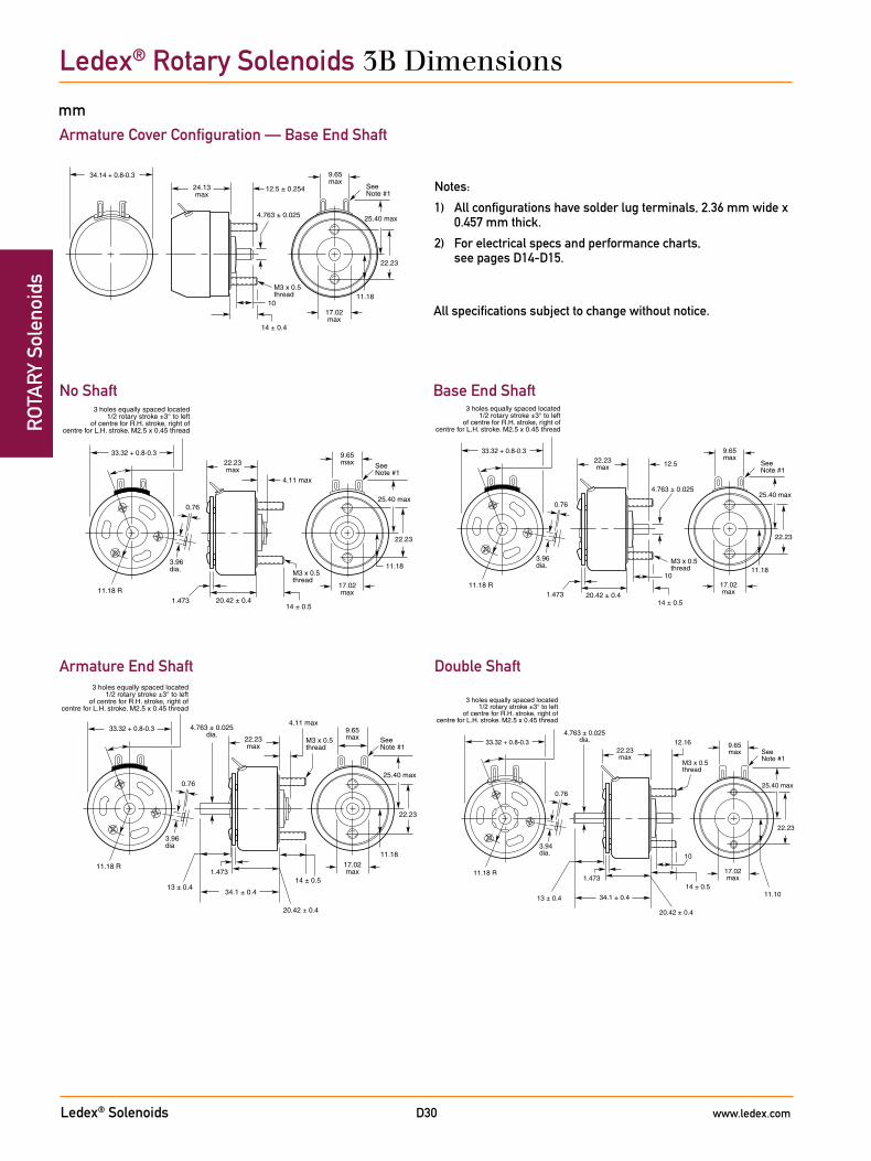
Ledex® Solenoids www.ledex.comD30
ROT
ARY
Sol
enoi
dsLedex® Rotary Solenoids 3B Dimensions
Notes:
1) All configurations have solder lug terminals, 2.36 mm wide x 0.457 mm thick.
2) For electrical specs and performance charts, see pages D14-D15.
Armature Cover Configuration — Base End Shaft
Double ShaftArmature End Shaft
No Shaft Base End Shaft
All specifications subject to change without notice.
mm
M3 x 0.5thread
1.473
9.65max
17.02max
22.23
11.18
25.40 max
4.11 max 33.32 + 0.8-0.3
3 holes equally spaced located1/2 rotary stroke ±3° to left
of centre for R.H. stroke, right ofcentre for L.H. stroke. M2.5 x 0.45 thread
3.96dia
20.42 ± 0.4
13 ± 0.434.1 ± 0.4
14 ± 0.5
11.18 R
0.76
SeeNote #1
22.23max
4.763 ± 0.025dia.
4.763 ± 0.025
M3 x 0.5thread
1011.18
1.473
9.65max
17.02max
22.23
25.40 max
33.32 + 0.8-0.3
3 holes equally spaced located1/2 rotary stroke ±3° to left
of centre for R.H. stroke, right ofcentre for L.H. stroke. M2.5 x 0.45 thread
3.96dia.
20.42 ± 0.4
12.5
14 ± 0.5
11.18 R
0.76
SeeNote #1
22.23max
10
11.10
M3 x 0.5thread
1.473
9.65max
17.02max
22.23
25.40 max
3 holes equally spaced located1/2 rotary stroke ±3° to left
of centre for R.H. stroke, right ofcentre for L.H. stroke. M2.5 x 0.45 thread
3.94dia.
20.42 ± 0.4
13 ± 0.4 34.1 ± 0.4
14 ± 0.5
11.18 R
0.76
SeeNote #1
22.23max
4.763 ± 0.025dia. 12.16 33.32 + 0.8-0.3
4.11 max
11.18M3 x 0.5thread
1.473
9.65max
17.02max
22.23
25.40 max
33.32 + 0.8-0.3
3 holes equally spaced located1/2 rotary stroke ±3° to left
of centre for R.H. stroke, right ofcentre for L.H. stroke. M2.5 x 0.45 thread
3.96dia.
20.42 ± 0.414 ± 0.5
11.18 R
0.76
SeeNote #1
22.23max
24.13max
4.763 ± 0.025
M3 x 0.5thread
1011.18
9.65max
17.02max
22.23
25.40 max
34.14 + 0.8-0.3
12.5 ± 0.254
14 ± 0.4
SeeNote #1
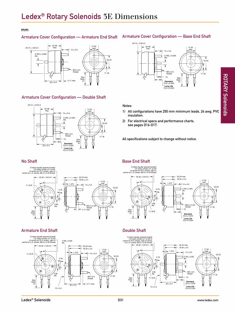
Ledex® Solenoids www.ledex.comD31
ROTA
RY SolenoidsLedex® Rotary Solenoids 3E Dimensions
Notes:
1) All configurations have 250 mm minimum leads, 24 awg, PVC insulation.
2) For electrical specs and performance charts, see pages D16-D17.
mm
Armature Cover Configuration — Armature End Shaft Armature Cover Configuration — Base End Shaft
Armature Cover Configuration — Double Shaft
Double ShaftArmature End Shaft
No Shaft Base End Shaft
All specifications subject to change without notice.
1.473
22.23
M3 x 0.5thread
11.18
17.02max
33.32 + 0.8-0.3
3 holes equally spaced located1/2 rotary stroke ±3° to left
of centre for R.H. stroke, right ofcentre for L.H. stroke. M2.5 x 0.45 thread
3.96dia.
0.76
32 ± 0.4
13 ± 0.4
4.11 max
11.18 R
SeeNote
#1
4.762 ± 0.025 dia.
14 ± 0.4
18.34 ± 0.420.24 max
4.762 ± 0.025dia.
4.11 max
M3 x 0.5thread
22.23
11.18
17.02max34.14 + 0.8-0.3
SeeNote
#1
14 ± 0.5
32 ± 0.4
22.48max
M3 x 0.5thread
10
Long Life12.9 ± 0.254
Standard12.6 ± 0.254
1.473
22.23
11.18
17.02max
33.32 + 0.8-0.3
3 holes equally spaced located1/2 rotary stroke ±3° to left of
centre for R.H. stroke, right of centrefor L.H. stroke. M2.5 x 0.45 thread
3.96dia.
0.76
32 ± 0.4
13 ± 0.4
11.18 RSeeNote
#1
4.762 ± 0.025 dia.
14 ± 0.5
18.34 ± 0.420.24 max
M3 x 0.5thread
10
4.762 ± 0.025dia.
22.23
11.18
17.02max
34.14 + 0.8-0.3
SeeNote
#1
14 ± 0.5
32 ± 0.4
22.48max
Long Life12.9 ± 0.254
Standard12.6 ± 0.254
4.11 max
M2.5 x 0.45thread
1.473
22.23
11.18
17.02max
33.32 + 0.8-0.3
3 holes equally spaced located1/2 rotary stroke ±3° to left
of centre for R.H. stroke, right ofcentre for L.H. stroke. M2.5 x 0.45 thread
3.96dia.
0.76
11.18 R
SeeNote
#1
14 ± 0.5
18.34 ± 0.420.24 max
M2.5 x 0.45thread
10
1.473
22.23
11.18
17.02max
33.32 + 0.8-0.3
3 holes equally spaced located1/2 rotary stroke ±3° to left
of centre for R.H. stroke, right ofcentre for L.H. stroke. M2.5 x 0.45 thread
3.96dia.
0.76
11.18 RSee
Note#1
4.762 ± 0.025 dia.
14 ± 0.5
18.34 ± 0.420.24 max
Long Life12.9 ± 0.254
Standard12.6 ± 0.254
10
Long Life12.9 ± 0.254
Standard12.6 ± 0.254
4.762 ± 0.025dia.
M3 x 0.5thread
22.23
11.18
17.02max
34.14 + 0.8-0.3
SeeNote
#1
14 ± 0.5
22.48max
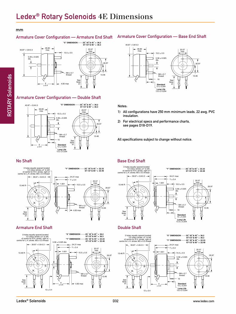
Ledex® Solenoids www.ledex.comD32
ROT
ARY
Sol
enoi
dsLedex® Rotary Solenoids 4E Dimensions
Notes:
1) All configurations have 250 mm minimum leads, 22 awg, PVC insulation.
2) For electrical specs and performance charts, see pages D18-D19.
mm
Armature Cover Configuration — Armature End Shaft Armature Cover Configuration — Base End Shaft
Armature Cover Configuration — Double Shaft
Double ShaftArmature End Shaft
No Shaft Base End Shaft
All specifications subject to change without notice.
1.651
20.57max
26.97
M4 x 0.7thread
24.21 max
13.46
Y ± 0.4
X± 0.4
5.56 ± 0.025 dia.
"X" DIMENSION - - - - 25, 35 & 4567-1/2 & 95
==
36.236.3
"Y" DIMENSION - - - - 25, 35 & 4567-1/2 & 95
==
22.3322.48
39.67 + 0.8-0.3
3 holes equally spaced located1/2 rotary stroke ±3° to left
of centre for R.H. stroke, right ofcentre for L.H. stroke. M3 x 0.5 thread
13 ± 0.4
4.83 max
13.46 R
SeeNote
#1
15.5 ± 0.5
26.97
13.46M4 x 0.7thread
"X" DIMENSION - - - - 25, 35 & 4567-1/2 & 95
==
36.236.3
5.56 ± 0.025dia.
4.83 max
20.57max
40.87 + 0.8-0.3
SeeNote
#1
15.5 ± 0.5
X± 0.4
26.80max
10
M4 x 0.7thread
13 ± 0.4
"X" DIMENSION - - - - 25, 35 & 4567-1/2 & 95
==
36.236.3
"Y" DIMENSION - - - - 25, 35 & 4567-1/2 & 95
==
22.3322.48
1.65120.57max
26.97
24.21 max
13.46
Y ± 0.4
X± 0.4
5.56 ± 0.025 dia.
39.67 + 0.8-0.3
3 holes equally spaced located1/2 rotary stroke ±3° to left
of centre for R.H. stroke, right ofcentre for L.H. stroke. M3 x 0.5 thread
13.46 R
SeeNote
#1
15.5 ± 0.5
Long Life13.3 ± 0.254
Standard13 ± 0.254
10
M4 x 0.7thread
"X" DIMENSION - - - - 25, 35 & 4567-1/2 & 95
==
36.236.3
26.97
13.46
5.56 ± 0.025dia.
20.57max
40.87 + 0.8-0.3
SeeNote
#1
15.5 ± 0.5
X± 0.4
26.80max
Long Life13.3 ± 0.254
Standard13 ± 0.254
M4 x 0.7thread
1.651
"Y" DIMENSION - - - - 25, 35 & 4567-1/2 & 95
==
22.3322.48
20.57max
26.97
24.21 max
13.46
Y ± 0.4
39.67 + 0.8-0.3
3 holes equally spaced located1/2 rotary stroke ±3° to left
of centre for R.H. stroke, right ofcentre for L.H. stroke. M3 x 0.5 thread
4.83 max
13.46 R
SeeNote
#1
15.5 ± 0.5
"Y" DIMENSION - - - - 25, 35 & 4567-1/2 & 95
==
22.3322.48
10
M4 x 0.7thread
1.65120.57max
26.97
24.21 max
13.46
Y ± 0.4
5.56 ± 0.025 dia.
39.67 + 0.8-0.3
3 holes equally spaced located1/2 rotary stroke ±3° to left
of centre for R.H. stroke, right ofcentre for L.H. stroke. M3 x 0.5 thread
13.46 R
SeeNote
#1
15.5 ± 0.5
Long Life13.3 ± 0.254
Standard13 ± 0.254
10
M4 x 0.7thread
26.97
13.46
5.56 ± 0.025dia.
20.57max
40.87 + 0.8-0.3
SeeNote
#1
15.5 ± 0.5
26.80max
Long Life13.3 ± 0.254
Standard13 ± 0.254
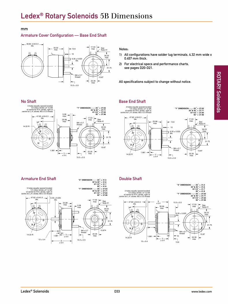
Ledex® Solenoids www.ledex.comD33
ROTA
RY Solenoids
Notes:
1) All configurations have solder lug terminals, 4.32 mm wide x 0.457 mm thick.
2) For electrical specs and performance charts, see pages D20-D21.
Ledex® Rotary Solenoids 5B Dimensions
Armature Cover Configuration — Base End Shaft
Double ShaftArmature End Shaft
No Shaft Base End Shaft
All specifications subject to change without notice.
mm
M4 x 0.7thread
1.981
X± 0.4
Y± 0.4
14.22 R
"X" DIMENSION - - - - 2535 & 45
67-1/295
====
41.541.641.741.8
"Y" DIMENSION - - - - 2535 & 45
67-1/295
====
27.6327.7127.8427.96
22.35max
30.23max
5.08max
17.53max
25.98max
31.75
15.5 ± 0.513 ± 0.4
15.874
47.62 +0.8-0.3dia.
SeeNote #1
6.35 ± 0.025dia.
3 holes equally spaced located1/2 rotary stroke ±3° to left
of centre for R.H. stroke, right ofcentre for L.H. stroke. M3 x 0.5 thread
M4 x 0.7thread
10
"X" DIMENSION - - - - 2535 & 45
67-1/295
====
41.541.641.741.8
"Y" DIMENSION - - - - 2535 & 45
67-1/295
====
27.6327.7127.8427.96
1.981
X± 0.4
Y± 0.4
14.22 R 22.35max
30.23max
30.56max
17.53max
31.75
15.5 ± 0.5
13 ± 0.4 13.6
15.87
47.62 +0.8-0.3dia.
SeeNote #1
6.35 ± 0.025dia.
3 holes equally spaced located1/2 rotary stroke ±3° to left
of centre for R.H. stroke, right ofcentre for L.H. stroke. M3 x 0.5 thread
M4 x 0.7thread
"Y" DIMENSION - - - - 2535 & 45
67-1/295
====
27.6327.7127.8427.96
1.981
Y± 0.4
14.22 R
22.35max
30.23max
5.08max
25.98max
17.53max
31.75
15.5 ± 0.5
15.87
47.62 +0.8-0.3dia.
SeeNote #1
3 holes equally spaced located1/2 rotary stroke ±3° to left
of centre for R.H. stroke, right ofcentre for L.H. stroke. M3 x 0.5 thread
6.35 ± 0.025dia.
10
M4 x 0.7thread
"Y" DIMENSION - - - - 2535 & 45
67-1/295
====
27.6327.7127.8427.96
1.981Y
± 0.414.22 R 22.35
max
30.23max
25.98max
17.53max
31.75
15.5 ± 0.5
15.87
13.6
47.62 +0.8-0.3dia.
SeeNote #1
3 holes equally spaced located1/2 rotary stroke ±3° to left
of centre for R.H. stroke, right ofcentre for L.H. stroke. M3 x 0.5 thread
M4 x 0.7thread
17.53max
1030.23max
22.35max
33.02max
31.75
15.5 ± 0.5
15.87
13.6
48.82 +0.8-0.3dia.
SeeNote #1
6.35 ± 0.025dia.
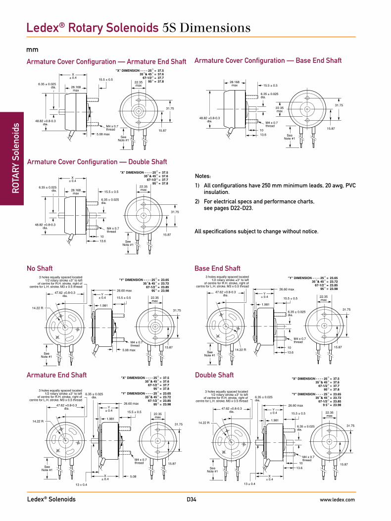
Ledex® Solenoids www.ledex.comD34
ROT
ARY
Sol
enoi
dsLedex® Rotary Solenoids 5S Dimensions
Notes:
1) All configurations have 250 mm minimum leads, 20 awg, PVC insulation.
2) For electrical specs and performance charts, see pages D22-D23.
mm
Armature Cover Configuration — Armature End Shaft Armature Cover Configuration — Base End Shaft
Armature Cover Configuration — Double Shaft
Double ShaftArmature End Shaft
No Shaft Base End Shaft
All specifications subject to change without notice.
5.08
26.60 max
"X" DIMENSION - - - - 2535 & 45
67-1/295
====
37.537.6 37.737.8
"Y" DIMENSION - - - - 2535 & 45
67-1/295
====
23.6523.7223.8523.98
M4 x 0.7thread
1.981
X± 0.4
Y± 0.4
14.22 R
22.35max
31.75
15.5 ± 0.5
13 ± 0.4
15.87
47.62 +0.8-0.3dia.
SeeNote #1
6.35 ± 0.025dia.
3 holes equally spaced located1/2 rotary stroke ±3° to left
of centre for R.H. stroke, right ofcentre for L.H. stroke. M3 x 0.5 thread
M4 x 0.7thread
5.08 max
28.168max
"X" DIMENSION - - - - 2535 & 45
67-1/295
====
37.537.6 37.737.8
X± 0.4
22.35max
31.75
15.5 ± 0.5
15.87
48.82 +0.8-0.3dia.
SeeNote #1
6.35 ± 0.025dia.
M4 x 0.7thread
10
"X" DIMENSION - - - - 2535 & 45
67-1/295
====
37.537.6 37.737.8
"Y" DIMENSION - - - - 2535 & 45
67-1/29 5
====
23.6523.7223.8523.9826.60 max
1.981
X± 0.4
Y± 0.4
14.22 R
22.35max
31.75
15.5 ± 0.5
13 ± 0.4
13.615.87
47.62 +0.8-0.3dia.
SeeNote #1
6.35 ± 0.025dia.
6.35 ± 0.025dia.
3 holes equally spaced located1/2 rotary stroke ±3° to left
of centre for R.H. stroke, right ofcentre for L.H. stroke. M3 x 0.5 thread
10
"X" DIMENSION - - - - 2535 & 45
67-1/295
====
37.537.637.737.8
M4 x 0.7thread
28.168max
X± 0.4
22.35max
31.75
15.5 ± 0.5
15.87
13.6
48.82 +0.8-0.3dia.
SeeNote #1
6.35 ± 0.025dia.
6.35 ± 0.025dia.
5.08 max
M4 x 0.7thread
"Y" DIMENSION - - - - 2535 & 45
67-1/295
====
23.6523.7223.8523.9826.60 max
1.981
Y± 0.4
14.22 R
22.35max
31.75
15.5 ± 0.5
15.87
47.62 +0.8-0.3dia.
SeeNote #1
3 holes equally spaced located1/2 rotary stroke ±3° to left
of centre for R.H. stroke, right ofcentre for L.H. stroke. M3 x 0.5 thread
"Y" DIMENSION - - - - 2535 & 45
67-1/295
====
23.6523.7223.8523.98
M4 x 0.7thread
26.60 max
1.981
Y± 0.4
14.22 R
22.35max
31.75
15.5 ± 0.5
15.87
47.62 +0.8-0.3dia.
SeeNote #1
3 holes equally spaced located1/2 rotary stroke ±3° to left
of centre for R.H. stroke, right ofcentre for L.H. stroke. M3 x 0.5 thread
10
13.6
6.35 ± 0.025dia.
10
M4 x 0.7thread
28.168max
22.35max
31.75
15.5 ± 0.5
15.87
13.6
48.82 +0.8-0.3dia.
SeeNote #1
6.35 ± 0.025dia.

Ledex® Solenoids www.ledex.comD35
ROTA
RY SolenoidsLedex® Rotary Solenoids 6S Dimensions
Notes:
1) All configurations have 250 mm minimum leads, 20 awg, PVC insulation.
2) For electrical specs and performance charts, see pages D24-D25.
mm
Armature Cover Configuration — Armature End Shaft Armature Cover Configuration — Base End Shaft
Armature Cover Configuration — Double Shaft
Double ShaftArmature End Shaft
No Shaft Base End Shaft
All specifications subject to change without notice.
19.05 R2.769
M5 x 0.8thread
6.35 max
18.29
34.11 max
"X" DIMENSION - - - - 2535
45, 67-1/2, & 95
===
47.9047.9548.00
"Y" DIMENSION - - - - 2535
45, 67-1/2, & 95
===
31.0131.0631.14
X± 0.4
Y ± 0.426.16max
36.52
18.5 ± 0.5
14 ± 0.4
57.15 +0.8-0.3dia.
SeeNote #1
7.937 ± 0.025dia.
3 holes equally spaced located1/2 rotary stroke ±3° to left
of centre for R.H. stroke, right ofcentre for L.H. stroke. M4 x 0.7 thread
18.29
"X" DIMENSION - - - - 2535
45, 67-1/2, & 95
===
47.9047.9548.00
M5 x 0.8thread
6.35 max
36.12max
X± 0.4
26.16max
36.52
18.5 ± 0.5
58.72 +0.8-0.3dia.
SeeNote #1
7.937 ± 0.025dia.
13
17.2
19.05 R
"X" DIMENSION - - - - 2535
45, 67-1/2, & 95
===
47.7847.8347.90
"Y" DIMENSION - - - - 2535
45, 67-1/2, & 95
===
31.0131.0631.14
2.769
M5 x 0.8thread
18.29
34.11 max
X± 0.4
Y ± 0.426.16max
36.52
18.5 ± 0.5
16 ± 0.4
57.15 +0.8-0.3dia.
SeeNote #1
7.937 ± 0.025dia.
3 holes equally spaced located1/2 rotary stroke ±3° to left
of centre for R.H. stroke, right ofcentre for L.H. stroke. M4 x 0.7 thread
13
17.2
"X" DIMENSION - - - - 2535
45, 67-1/2, & 95
===
47.9047.9548.00
18.29
M5 x 0.8thread
36.12max
X± 0.4
26.16max
36.52
18.5 ± 0.5
58.72 +0.8-0.3dia.
SeeNote #1
7.937 ± 0.025dia.
6.35 max
"Y" DIMENSION - - - - 2535
45, 67-1/2, & 95
===
31.0131.0631.14
19.05 R2.769
M5 x 0.8thread
18.29
34.11 maxY ± 0.4 26.16
max
36.52
18.5 ± 0.5
57.15 +0.8-0.3dia.
SeeNote #1
3 holes equally spaced located1/2 rotary stroke ±3° to left
of centre for R.H. stroke, right ofcentre for L.H. stroke. M4 x 0.7 thread
7.937 ± 0.025dia.
13
17.2
"Y" DIMENSION - - - - 2535
45, 67-1/2, & 95
===
31.0131.0631.14
19.05 R2.769
M5 x 0.8thread
18.29
34.11 max
Y ± 0.426.16max
36.52
18.5 ± 0.5
57.15 +0.8-0.3dia.
SeeNote #1
3 holes equally spaced located1/2 rotary stroke ±3° to left
of centre for R.H. stroke, right ofcentre for L.H. stroke. M4 x 0.7 thread
1317.2
18.29
M5 x 0.8thread
36.12max
26.16max
36.52
18.5 ± 0.5
58.72 +0.8-0.3dia.
SeeNote #1
7.937 ± 0.025dia.
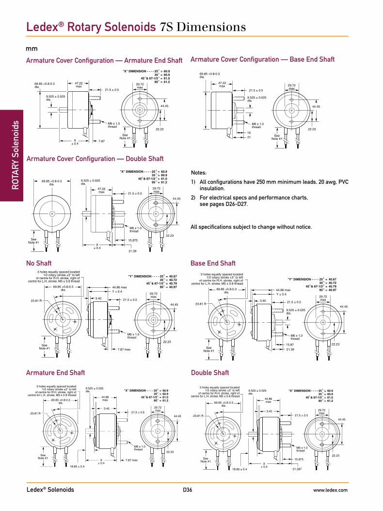
Ledex® Solenoids www.ledex.comD36
ROT
ARY
Sol
enoi
dsLedex® Rotary Solenoids 7S Dimensions
Notes:
1) All configurations have 250 mm minimum leads, 20 awg, PVC insulation.
2) For electrical specs and performance charts, see pages D26-D27.
mm
Armature Cover Configuration — Armature End Shaft Armature Cover Configuration — Base End Shaft
Armature Cover Configuration — Double Shaft
Double ShaftArmature End Shaft
No Shaft Base End Shaft
All specifications subject to change without notice.
M6 x 1.0thread
9.525 ± 0.025dia.
7.87 max
22.23
"X" DIMENSION - - - - 2535
45 & 67-1/295
====
60.960.961.061.2
44.86max
3.40
23.81 R
X± 0.4
29.72max
44.4521.5 ± 0.5
18.85 ± 0.4
69.85 +0.8-0.3dia.
SeeNote #1
3 holes equally spaced located1/2 rotary stroke ±3° to left
of centre for R.H. stroke, right ofcentre for L.H. stroke. M5 x 0.8 thread
M6 x 1.0thread
15.875
21.387
"X" DIMENSION - - - - 2535
45 & 67-1/295
====
60.960.961.061.2
9.525 ± 0.025dia.
22.23
44.86max
3.40
23.81 R
X± 0.4
29.72max
44.4521.5 ± 0.5
18.85 ± 0.4
69.85 +0.8-0.3dia.
SeeNote #1
3 holes equally spaced located1/2 rotary stroke ±3° to left
of centre for R.H. stroke, right ofcentre for L.H. stroke. M5 x 0.8 thread
7.87 max
M6 x 1.0thread
"Y" DIMENSION - - - - 2535
45 & 67-1/295
====
40.6740.7240.7940.97
22.23
44.86 max
3.4023.81 R
Y ± 0.429.72max
44.45
21.5 ± 0.5
69.85 +0.8-0.3dia.
SeeNote #1
3 holes equally spaced located1/2 rotary stroke ±3° to left
of centre for R.H. stroke, right ofcentre for L.H. stroke. M5 x 0.8 thread
7.87
47.22max
"X" DIMENSION - - - - 2535
45 & 67-1/295
====
60.960.961.061.2
9.525 ± 0.025dia.
M6 x 1.0thread
22.23
X± 0.4
29.72max
44.45
21.5 ± 0.5
69.85 +0.8-0.3dia.
SeeNote #1
9.525 ± 0.025dia.
15.87
21.39
"Y" DIMENSION - - - - 2535
45 & 67-1/295
====
40.6740.7240.7940.97
M6 x 1.0thread
22.23
44.86 max
3.4023.81 R
Y ± 0.429.72max
44.45
21.5 ± 0.5
69.85 +0.8-0.3dia.
SeeNote #1
3 holes equally spaced located1/2 rotary stroke ±3° to left
of centre for R.H. stroke, right ofcentre for L.H. stroke. M5 x 0.8 thread
M6 x 1.0thread
16
47.22max
9.525 ± 0.025dia.
22.23
29.72max
44.45
21.5 ± 0.5
21
69.85 +0.8-0.3dia.
SeeNote #1
M6 x 1.0thread
15.875
"X" DIMENSION - - - - 2535
45 & 67-1/295
====
60.960.961.061.2
47.22max
9.525 ± 0.025dia.
22.23
X± 0.4
29.72max
44.45
21.5 ± 0.5
21.39
69.85 +0.8-0.3dia.
SeeNote #1
Related Documents