Intelligent Embedded Solutions, Unit 2, Berkshire Business Centre, Berkshire Drive, Thatcham, Berkshire, RG19 4EW Telephone : +44 (0)1635 294600 Fax : +44 (0)1635 869200 Email: [email protected] www.i-sbc.com A division of Intelligent Group Solutions Ltd 1 © IGS Version V1 March 2015 DATASHEET LED Lighting Shield for Arduino™ and Raspberry-Pi™ IES-SHIELD-RGBW Product Overview The IES-SHIELD-RGBW is a four [4] channel high current LED driver shield capable of driving four [4] 1-12 LED chains. Specifically targeted at the Arduino UNO board user [all other Arduino boards supported] and the Raspberry-Pi. The RGBW features high speed I 2 C communication for easy project integration and smooth brightness control. Each of the four [4] 350mA capable channels features a 1024 step brightness control, open/short circuit protection, current monitoring and can support a LED chain of 1- 12 LED’s [dependant on power supply connected]. This allows the user to create RGBW lighting effects, using the supplied RGBW lamp, or driving external RGB strips /coins etc. or 4x white strips /coins for accent lighting, room lighting, aquarium lighting etc. The built in aquarium mode provides advanced control of the supplied RGBW lamp, or external 10Watt RGBW lamp, to provide simulation of moonlight, sunrise, day and sunset cycles which run on an internal 24 hour timer. The on-board I 2 C pull-ups are jumper configurable to allow disconnection when connecting to the Raspberry-Pi, which has its own pull-ups. The supplied RGBW 4W lamp features high quality OSRAM OSLON LED’s, finned heatsink and has a maximum light output level of 340 lumens. Applications The IES-SHIELD-RGBW has many applications in domestic room lighting, outside lighting, fish ponds, accent lighting and aquarium lighting to name a few. The built in aquarium mode provides timed set and forget moonlight/sunrise/sunset simulation for large or small aquariums. Technical Features z Arduino TM UNO Shield standard form factor for simple integration into any Arduino project z I 2 C interface for simple connection to Arduino or Raspberry-Pi z A complete mono or colour lighting system for rooms, aquariums, fish ponds, external lighting etc. z Four [4] high current [350mA each] LED driver channels supporting 1-12 LED’s per string [1.75 to 17Watts (5- 48VDC supply)]. z I 2 C address links allow up to four [4] shields to be used together z Simple register based control of brightness / colour and sunrise, sunset and moonlight simulation modes z RGBW high brightness LED module with heatsink supplied as standard [other modules available] z LVD, RoHS and WEEE compliant product

Welcome message from author
This document is posted to help you gain knowledge. Please leave a comment to let me know what you think about it! Share it to your friends and learn new things together.
Transcript

Intelligent Embedded Solutions, Unit 2, Berkshire Business Centre, Berkshire Drive, Thatcham, Berkshire, RG19 4EWTelephone : +44 (0)1635 294600 Fax : +44 (0)1635 869200 Email: [email protected] www.i-sbc.comA division of Intelligent Group Solutions Ltd
1
© IG
S V
ersio
n V1
Mar
ch 2
015
DA
TASH
EET
LED Lighting Shield for Arduino™ and Raspberry-Pi™IES-SHIELD-RGBW
Product OverviewThe IES-SHIELD-RGBW is a four [4] channel high current LED driver shield capable of driving four [4] 1-12 LED chains. Specifically targeted at the Arduino UNO board user [all other Arduino boards supported] and the Raspberry-Pi. The RGBW features high speed I2C communication for easy project integration and smooth brightness control.
Each of the four [4] 350mA capable channels features a 1024 step brightness control, open/short circuit protection, current monitoring and can support a LED chain of 1- 12 LED’s [dependant on power supply connected]. This allows the user to create RGBW lighting effects, using the supplied RGBW lamp, or driving external RGB strips /coins etc. or 4x white strips /coins for accent lighting, room lighting, aquarium lighting etc.
The built in aquarium mode provides advanced control of the supplied RGBW lamp, or external 10Watt RGBW lamp, to provide simulation of moonlight, sunrise, day and sunset cycles which run on an internal 24 hour timer.
The on-board I2C pull-ups are jumper configurable to allow disconnection when connecting to the Raspberry-Pi, which has its own pull-ups.
The supplied RGBW 4W lamp features high quality OSRAM OSLON LED’s, finned heatsink and has a maximum light output level of 340 lumens.
ApplicationsThe IES-SHIELD-RGBW has many applications in domestic room lighting, outside lighting, fish ponds, accent lighting and aquarium lighting to name a few. The built in aquarium mode provides timed set and forget moonlight/sunrise/sunset simulation for large or small aquariums.
Technical Features z ArduinoTM UNO Shield standard form factor for simple integration into any Arduino project
z I2C interface for simple connection to Arduino or Raspberry-Pi
z A complete mono or colour lighting system for rooms, aquariums, fish ponds, external lighting etc.
z Four [4] high current [350mA each] LED driver channels supporting 1-12 LED’s per string [1.75 to 17Watts (5-48VDC supply)].
z I2C address links allow up to four [4] shields to be used together
z Simple register based control of brightness / colour and sunrise, sunset and moonlight simulation modes
z RGBW high brightness LED module with heatsink supplied as standard [other modules available]
z LVD, RoHS and WEEE compliant product

www.i-sbc.com
Intelligent Embedded Solutions, Unit 2, Berkshire Business Centre, Berkshire Drive, Thatcham, Berkshire, RG19 4EWTelephone : +44 (0)1635 294600 Fax : +44 (0)1635 869200 Email: [email protected] www.i-sbc.comA division of Intelligent Group Solutions Ltd
2
© IG
S V
ersio
n V1
Mar
ch 2
015
DA
TASH
EET
Products
IES PART NUMBER Description
IES-SHIELD-RGBW LED Lighting Shield RGBW LED lamp
* Raspberry-Pi, Arduino, NANO, UNO & MEGA are trademarkNote: A 12VDC [500mA] power supply is required
Power RequirementsThe IES-SHIELD-RGBW requires two power supplies for operation.
Controller power The power necessary for on-board controller operation (approx. 2- 10mA) is taken from an external battery, mains power adaptor or from the Arduino or Raspberry-Pi board.
The RGBW provides three PCB pads, two marked ‘GND’ and one marked ‘Vin’ in the same format as that present on the UNO board, which should be connected to negative and positive battery/power supply terminals respectively. The input voltage range is 4.75 - 16VDC with the internal circuitry being protected against power supply reversal.
LED power
The power necessary for LED operation is taken from an external battery or mains power adaptor. Connection of the external supply to the RGBW module is through a two (2) way pluggable screw terminal block marked ‘48VDC MAX’. The positive connection is marked ‘+++++’ but is internally polarity protected to prevent damage to the LED drivers.
A supply voltage should be selected dependant on the number of LED’s connected in series as a chain to the LED output. A good rule of thumb is [Number of LED’s in string x 4V] but a minimum input voltage of 12VDC is recommended.
Examples:
Each channel has 6x RED, BLUE and GREEN LED’s connected in a series chain, therefore input supply = 6 x 4V = 24VDC.
Each channel has 12x RED, BLUE and GREEN LED’s connected in a series chain, therefore input supply = 12 x 4V = 48VDC.
DO NOT exceed the maximum input voltage of 48VDC !A supply of 12VDC @ 500mA is recommended for the supplied RGBW 4W lamp.
LED ConnectionThe LED interface is an eight (8) pin horizontal 2.54mm pitch header, pinned as follows:
RED -
RED +
GREEN -
GREEN +
BLUE -
BLUE +
WHITE -
WHITE +
The corresponding chain of coloured LED’s should be connected
with its CATHODE connected to ‘-‘ and its ANODE end connected to ‘+’.
I2C ConnectionThe I2C connections are marked ‘SDA’ and ‘SCL’ and allow connection to the Arduino UNO board ‘ANALOG IN’ pins 4 and 5 or the Rasperberry-Pi GPIO port pins 3 and 5 (see Fig. 2.0) or another I2C Master device.
The IES-SHIELD-RGBW is fitted with pull-up jumpers that can be configured to provide the source current necessary for I2C communication. The following jumpers should normally be set when using the UNO board, as long as the I2C bus does not have existing pull-up’s provided by another device. These jumpers MUST be removed when using the Raspberry-Pi:
SDA
SCL
PULL UP
www.i-sbc.com
Intelligent Embedded Solutions, Unit 2, Berkshire Business Centre, Berkshire Drive, Thatcham, Berkshire, RG19 4EWTelephone : +44 (0)1635 294600 Fax : +44 (0)1635 869200 Email: [email protected] www.i-sbc.comA division of Intelligent Group Solutions Ltd
3
© IG
S V
ersio
n V1
Mar
ch 2
015
DA
TASH
EET
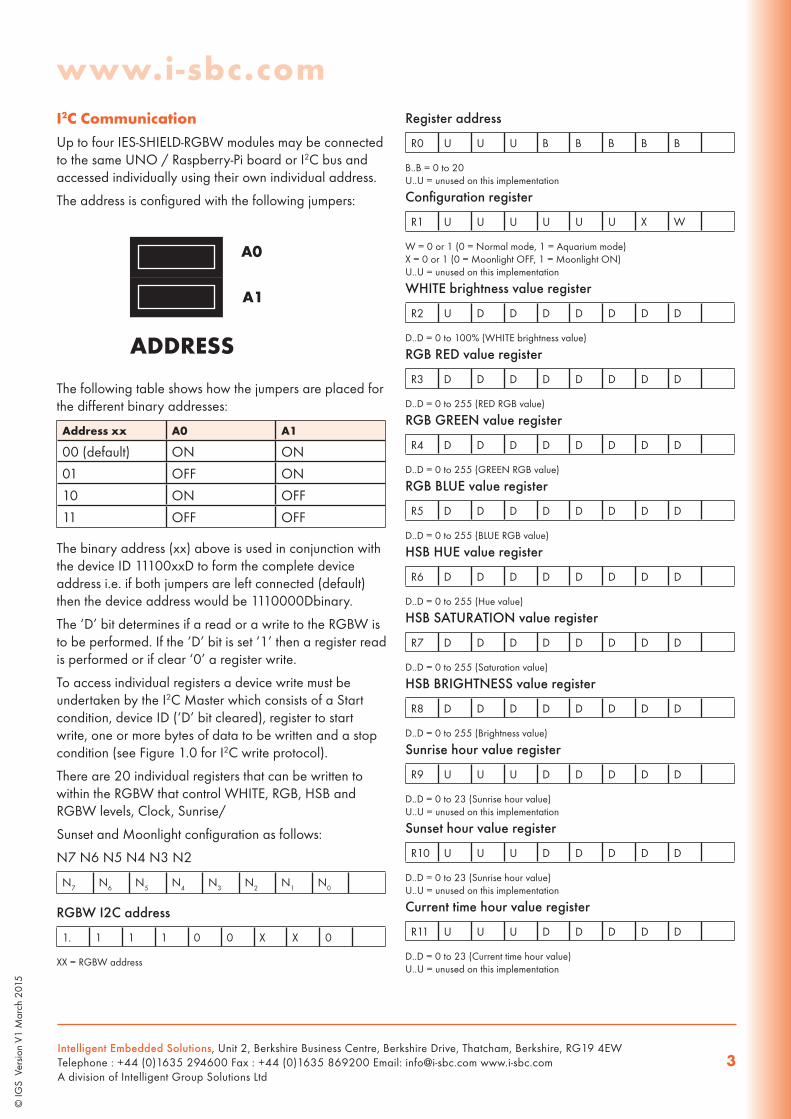
I2C CommunicationUp to four IES-SHIELD-RGBW modules may be connected to the same UNO / Raspberry-Pi board or I2C bus and accessed individually using their own individual address.
The address is configured with the following jumpers:
A0
A1
ADDRESS
The following table shows how the jumpers are placed for the different binary addresses:
Address xx A0 A1
00 (default) ON ON
01 OFF ON
10 ON OFF
11 OFF OFF
The binary address (xx) above is used in conjunction with the device ID 11100xxD to form the complete device address i.e. if both jumpers are left connected (default) then the device address would be 1110000Dbinary.
The ‘D’ bit determines if a read or a write to the RGBW is to be performed. If the ‘D’ bit is set ‘1’ then a register read is performed or if clear ‘0’ a register write.
To access individual registers a device write must be undertaken by the I2C Master which consists of a Start condition, device ID (‘D’ bit cleared), register to start write, one or more bytes of data to be written and a stop condition (see Figure 1.0 for I2C write protocol).
There are 20 individual registers that can be written to within the RGBW that control WHITE, RGB, HSB and RGBW levels, Clock, Sunrise/
Sunset and Moonlight configuration as follows:
N7 N6 N5 N4 N3 N2
N7 N6 N5 N4 N3 N2 N1 N0
RGBW I2C address
1. 1 1 1 0 0 X X 0
XX = RGBW address
Register address
R0 U U U B B B B B
B..B = 0 to 20U..U = unused on this implementation
Configuration register
R1 U U U U U U X W
W = 0 or 1 (0 = Normal mode, 1 = Aquarium mode)X = 0 or 1 (0 = Moonlight OFF, 1 = Moonlight ON)U..U = unused on this implementation
WHITE brightness value register
R2 U D D D D D D D
D..D = 0 to 100% (WHITE brightness value)
RGB RED value register
R3 D D D D D D D D
D..D = 0 to 255 (RED RGB value)
RGB GREEN value register
R4 D D D D D D D D
D..D = 0 to 255 (GREEN RGB value)
RGB BLUE value register
R5 D D D D D D D D
D..D = 0 to 255 (BLUE RGB value)
HSB HUE value register
R6 D D D D D D D D
D..D = 0 to 255 (Hue value)
HSB SATURATION value register
R7 D D D D D D D D
D..D = 0 to 255 (Saturation value)
HSB BRIGHTNESS value register
R8 D D D D D D D D
D..D = 0 to 255 (Brightness value)
Sunrise hour value register
R9 U U U D D D D D
D..D = 0 to 23 (Sunrise hour value)U..U = unused on this implementation
Sunset hour value register
R10 U U U D D D D D
D..D = 0 to 23 (Sunrise hour value)U..U = unused on this implementation
Current time hour value register
R11 U U U D D D D D
D..D = 0 to 23 (Current time hour value)U..U = unused on this implementation

www.i-sbc.com
Intelligent Embedded Solutions, Unit 2, Berkshire Business Centre, Berkshire Drive, Thatcham, Berkshire, RG19 4EWTelephone : +44 (0)1635 294600 Fax : +44 (0)1635 869200 Email: [email protected] www.i-sbc.comA division of Intelligent Group Solutions Ltd
4
© IG
S V
ersio
n V1
Mar
ch 2
015
DA
TASH
EET
Current minute value register
R12 U U D D D D D D
D..D = 0 to 59 (Current time minute value)U..U = unused on this implementation
RED brightness MSB register
R13 U U U U U U D D
D..D = 0x00 to 0x03 (MSB of brightness value)U..U = unused on this implementation
RED brightness LSB register
R14 D D D D D D D D
D..D = 0x00 to 0xFF (LSB of brightness value)
GREEN brightness MSB register
R15 U U U U U U D D
D..D = 0x00 to 0x03 (MSB of brightness value)U..U = unused on this implementation
GREEN brightness LSB register
R16 D D D D D D D D
D..D = 0x00 to 0xFF (LSB of brightness value)
BLUE brightness MSB register
R17 U U U U U U D D
D..D = 0x00 to 0x03 (MSB of brightness value)U..U = unused on this implementation
BLUE brightness LSB register
R18 D D D D D D D D
D..D = 0x00 to 0xFF (LSB of brightness value)
WHITE brightness MSB register
R19 U U U U U U D D
D..D = 0x00 to 0x03 (MSB of brightness value)U..U = unused on this implementation
WHITE brightness LSB register
R20 D D D D D D D D
D..D = 0x00 to 0xFF (LSB of brightness value)
The RGBW also auto increments the register specified for every additional write requested by the Master I2C device, which allows more than one register to be written in one transaction.
This allows for example Register 1 to Register 5, RGB and WHITE levels, to be written in one transaction (see Figure 1.1 for I2C write protocol).
To read individual data and status registers a device write then read must be undertaken by the I2C Master.
The write consists of a Start condition, device ID (‘D’ bit clear), register to start read and a Stop condition.
This is followed by a read, which consists of a Start condition, device ID (‘D‘ bit set), followed by data from the register specified and terminated with a Stop condition. Status registers
There are 12 individual registers that can be read within the RGBW as follows:
N7 N6 N5 N4 N3 N2 N1 N0
RGBW Address
1. 1 1 1 0 0 X X 1
XX = Address select pins
Configuration register
R1 U U U U U U X W
W = 0 or 1 (0 = Normal mode, 1 = Aquarium mode)X = 0 or 1 (0 = Moonlight OFF, 1 = Moonlight ON)U..U = unused on this implementation
RED brightness MSB register
R2 U U U U U U D D
D..D = 0x00 to 0x03 (MSB of brightness value)U..U = unused on this implementation
RED brightness LSB register
R3 U U U U U U D D
D..D = 0x00 to 0xFF (LSB of brightness value)
GREEN brightness MSB register
R4 U U U U U U D D
D..D = 0x00 to 0x03 (MSB of brightness value)U..U = unused on this implementation
GREEN brightness LSB register
R5 D D D D D D D D
D..D = 0x00 to 0xFF (LSB of brightness value)
BLUE brightness MSB register
R6 U U U U U U D D
D..D = 0x00 to 0x03 (MSB of brightness value)U..U = unused on this implementation
BLUE brightness LSB register
R7 D D D D D D D D
D..D = 0x00 to 0xFF (LSB of brightness value)
WHITE brightness MSB register
R8 U U U U U U D D
D..D = 0x00 to 0x03 (MSB of brightness value)U..U = unused on this implementation
WHITE brightness LSB register
R9 D D D D D D D D
D..D = 0x00 to 0xFF (LSB of brightness value)

www.i-sbc.com
Intelligent Embedded Solutions, Unit 2, Berkshire Business Centre, Berkshire Drive, Thatcham, Berkshire, RG19 4EWTelephone : +44 (0)1635 294600 Fax : +44 (0)1635 869200 Email: [email protected] www.i-sbc.comA division of Intelligent Group Solutions Ltd
5
© IG
S V
ersio
n V1
Mar
ch 2
015
DA
TASH
EET
Current time hours value register
R10 U U U D D D D D
D..D = 0 to 23 (Current hour value)U..U = unused on this implementation
Current time minutes value register
R11 U U D D D D D D
D..D = 0 to 59 (Current minutes value)U..U = unused on this implementation
IES-SHIELD-RGBW Firmware
R12 M M M M L L L L
L..L = Firmware minor version 0-15M..M = Firmware major version 0-15
RGB Colour Registers…The RGB colour registers allow a standard RED, GREEN, BLUE (sRGB) colour value to be displayed on the connected LED’s. The colour values set are internally converted to the CIE1931 XYZ colour space for better visual perception.
HSB Colour Registers…The HSB colour registers allow a HUE, SATURATION, BRIGHTNESS [also known as VALUE] colour value to be displayed on the connected LED’s. The colour values set are internally converted to the CIE1931 XYZ colour space for better visual perception.
RGBW Brightness Registers…The R.G.B.W brightness registers allow individual control of the brightness level on each of the four LEDs. The output level is adjustable from zero [0x0000], or OFF, to 1023 [0x03FF], or maximum brightness, by converting the value into hexadecimal and writing the Most Significant Byte [MSB] to the first register and the Least Significant Byte
[LSB] to the second register. For example if a brightness level of 589 was required the hexadecimal representation of this would be 0x024D. The 0x02 hex would be written to the first register and the 0x4D hex to the second.
These registers may also be read to return the internally converted RGB and HSB values.
Aquarium Mode…The IES-SHIELD-RGBW provides an aquarium mode of operation that can simulate sunrise/sunset and moonlight illumination.
Aquarium mode is simply enabled by writing the current time, hour and minute, into the I2C clock registers and then the sunrise hour, sunset hour and configuration control into the relevant I2C registers.
Sunrise is initiated when the clock and sunrise hour (06:00 default) are the same and will continue over a period of 30 minutes until full daylight is reached (5600K). Sunset is initiated when the clock and the sunset hour (21:00 default) are the same and will continue over a period of 30 minutes until darkness is reached.
If the moonlight flag is also set the moon will rise as darkness falls and remain constant during the night until sunrise starts once more.
www.i-sbc.com
Intelligent Embedded Solutions, Unit 2, Berkshire Business Centre, Berkshire Drive, Thatcham, Berkshire, RG19 4EWTelephone : +44 (0)1635 294600 Fax : +44 (0)1635 869200 Email: [email protected] www.i-sbc.comA division of Intelligent Group Solutions Ltd
6
© IG
S V
ersio
n V1
Mar
ch 2
015
DA
TASH
EET
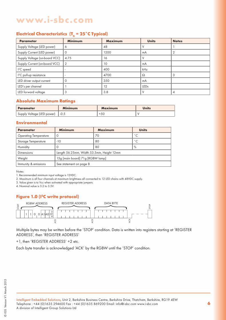
Electrical Characteristics (TA = 25˚C Typical)
Parameter Minimum Maximum Units Notes
Supply Voltage (LED power) 6 48 V 1
Supply Current (LED power) 0 1200 mA 2
Supply Voltage (on-board VCC) 4.75 16 V
Supply Current (on-board VCC) 2 10 mA
I2C speed - 400 kHz
I2C pull-up resistance - 4700 Ω 3
LED driver output current 0 350 mA
LED’s per channel 1 12 LEDs
LED forward voltage 3 3.8 V 4
Absolute Maximum Ratings
Parameter Minimum Maximum Units
Supply Voltage (LED power) -0.5 +50 V
Environmental
Parameter Minimum Maximum Units
Operating Temperature 0 70 ˚C
Storage Temperature -10 80 ˚C
Humidity 0 80 %
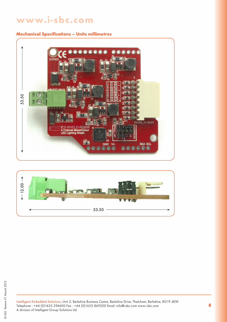
Dimensions Length 56.25mm, Width 53.5mm, Height 12mm
Weight 15g [main board] 71g [RGBW lamp]
Immunity & emissions See statement on page 8
Notes:1. Recommended minimum input voltage is 12VDC.2. Maximum is all four channels at maximum brightness all connected to 12 LED chains with 48VDC supply.3. Value given is to Vcc when activated with appropriate jumpers.4. Nominal value is 3.2 to 3.5V.
Figure 1.0 (I2C write protocol)RGBW ADDRESS REGISTER ADDRESS DATA BYTE
1 0 11 0 A1A0
R/W
-0
STA
RT
STO
P
AC
K
AC
K
AC
K
} } }
Multiple bytes may be written before the ‘STOP’ condition. Data is written into registers starting at ‘REGISTER ADDRESS’, then ‘REGISTER ADDRESS’
+1, then ‘REGISTER ADDRESS’ +2 etc.
Each byte transfer is acknowledged ‘ACK’ by the RGBW until the ‘STOP’ condition.
www.i-sbc.com
Intelligent Embedded Solutions, Unit 2, Berkshire Business Centre, Berkshire Drive, Thatcham, Berkshire, RG19 4EWTelephone : +44 (0)1635 294600 Fax : +44 (0)1635 869200 Email: [email protected] www.i-sbc.comA division of Intelligent Group Solutions Ltd
7
© IG
S V
ersio
n V1
Mar
ch 2
015
DA
TASH
EET
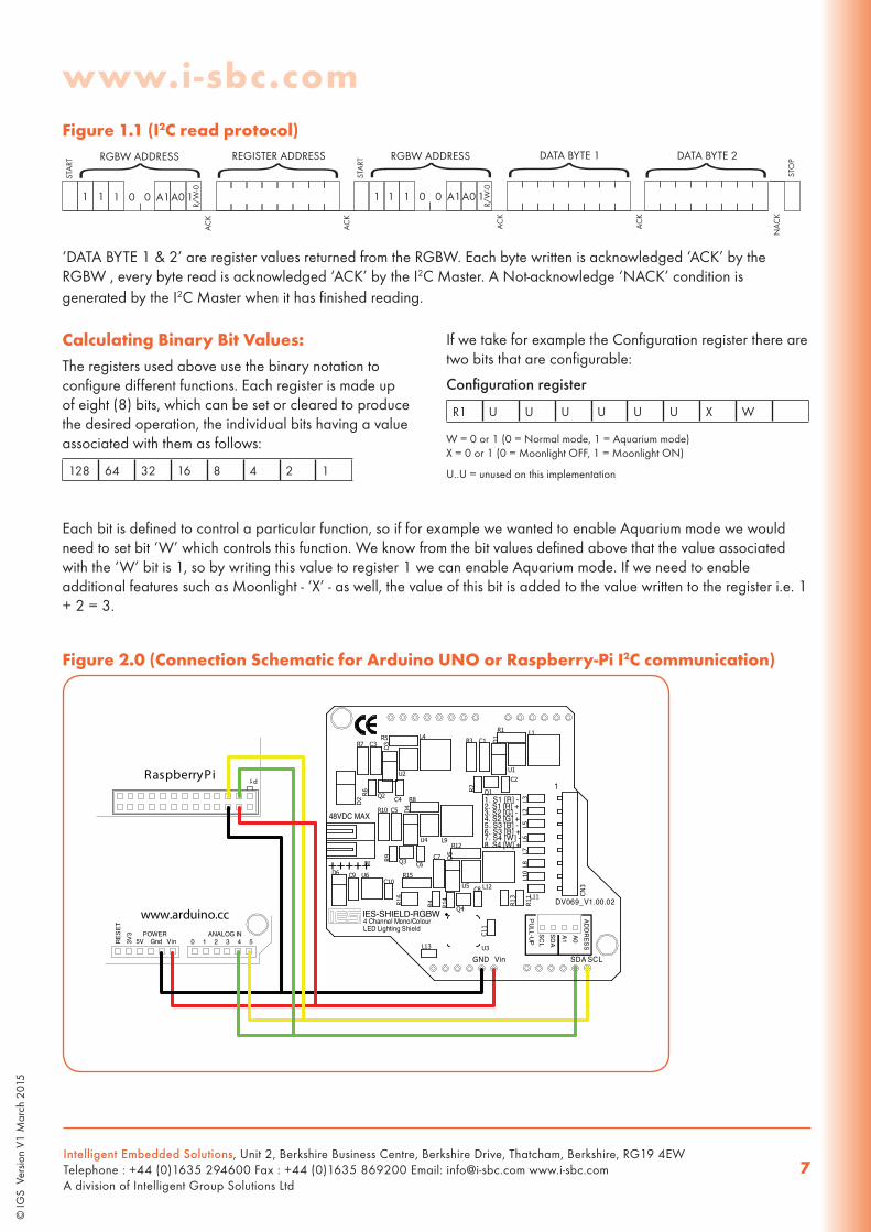
Figure 1.1 (I2C read protocol)RGBW ADDRESS REGISTER ADDRESS
11 11 00 A1A0R/
W-0
STA
RT
STO
P
AC
K
AC
K
AC
K
AC
K
NA
CK
} } RGBW ADDRESS DATA BYTE 1
11 1 10 0 A1A0
R/W
-0
} } DATA BYTE 2 }STA
RT
‘DATA BYTE 1 & 2’ are register values returned from the RGBW. Each byte written is acknowledged ‘ACK’ by the RGBW , every byte read is acknowledged ‘ACK’ by the I2C Master. A Not-acknowledge ‘NACK’ condition is generated by the I2C Master when it has finished reading.
Calculating Binary Bit Values:The registers used above use the binary notation to configure different functions. Each register is made up of eight (8) bits, which can be set or cleared to produce the desired operation, the individual bits having a value associated with them as follows:
128 64 32 16 8 4 2 1
If we take for example the Configuration register there are two bits that are configurable:
Configuration register
R1 U U U U U U X W
W = 0 or 1 (0 = Normal mode, 1 = Aquarium mode)X = 0 or 1 (0 = Moonlight OFF, 1 = Moonlight ON)
U..U = unused on this implementation
Each bit is defined to control a particular function, so if for example we wanted to enable Aquarium mode we would need to set bit ‘W’ which controls this function. We know from the bit values defined above that the value associated with the ‘W’ bit is 1, so by writing this value to register 1 we can enable Aquarium mode. If we need to enable additional features such as Moonlight - ‘X’ - as well, the value of this bit is added to the value written to the register i.e. 1 + 2 = 3.
Figure 2.0 (Connection Schematic for Arduino UNO or Raspberry-Pi I2C communication)
A0A1
SDA
SCL
PULL-UP
ADD
RESS
www.arduino.cc
RESE
T3V
3
5V Gnd Vin 0 1 2 3 4 5ANALOG INPOWER
P1Raspberry Pi
GND Vin SDA SCL
DV069_V1.00.02
4 Channel Mono/ColourLED Lighting Shield
+++++
48VDC MAX
1. S1 [R] -2. S1 [R] +3. S2 [G] -4. S2 [G] +5. S3 [B] -6. S3 [B] +7. S4 [W] -8. S4 [W] +
1
U1
L1
C2
Q1R2
R1
C1 D1R3
U2
L4
C4Q2R6
R5C3 D
3R7
U4 L9
C6Q3R9
R8
C5 D4R10
L3L5
L7L2
L6L8
U5 L12C8
Q4R14
R12
C7 D5
R15 L10
L11
U3
CN3
U6
R4 R11
R13
CN1
D2
D6C10
C9
L13
C11
R16
IES-SHIELD-RGBW
www.i-sbc.com
Intelligent Embedded Solutions, Unit 2, Berkshire Business Centre, Berkshire Drive, Thatcham, Berkshire, RG19 4EWTelephone : +44 (0)1635 294600 Fax : +44 (0)1635 869200 Email: [email protected] www.i-sbc.comA division of Intelligent Group Solutions Ltd
8
© IG
S V
ersio
n V1
Mar
ch 2
015
DA
TASH
EET
Mechanical Specifications – Units millimetres
53.5
0
53.50
12.0
0

www.i-sbc.com
Intelligent Embedded Solutions, Unit 2, Berkshire Business Centre, Berkshire Drive, Thatcham, Berkshire, RG19 4EWTelephone : +44 (0)1635 294600 Fax : +44 (0)1635 869200 Email: [email protected] www.i-sbc.comA division of Intelligent Group Solutions Ltd
9
© IG
S V
ersio
n V1
Mar
ch 2
015
DA
TASH
EET
WEEE Consumer NoticeThis product is subject to Directive 2002/96/EC of the European Parliament and the Council of the European Union on Waste of Electrical and Electronic Equipment (WEEE) and, in jurisdictions adopting that Directive, is marked as being put on the market after August 13, 2005, and should not be disposed of as unsorted municipal/public waste. Please utilise your local WEEE collection facilities in the disposition and otherwise observe all applicable requirements. For further information on the requirements regarding the disposition of this product in other languages please visit www.i-sbc.com
RoHS ComplianceThis product complies with Directive 2002/95/EC of the European Parliament and the Council of the European Union on the Restriction of Hazardous Substances (RoHS) which prohibits the use of various heavy metals (lead, mercury, cadmium, and hexavalent chromium), polybrominated biphenyls (PBB) and polybrominated diphenyl ethers (PBDE).
For further information please contact IESThe values contained in this data sheet can change due to technical innovations. Any such changes will be made without separate notification.
53.0
0
Related Documents


