1 Z4W-V LED Displacement Sensor Low-cost Displacement Sensor with 10-micron Resolution with Red LED ■ Measurement point: 25 mm; measurement range: 4 mm. ■ Easy adjustment, range/stable light indicators. ■ Easy-to-use built-in Amp. ■ High-speed response: 5 ms. ■ Visible beam spot. ■ Enclosure rating: IP66. Ordering Information Sensing distance Resolution Model 254 mm 10 m Z4W-V25R 5M

Welcome message from author
This document is posted to help you gain knowledge. Please leave a comment to let me know what you think about it! Share it to your friends and learn new things together.
Transcript
Z4W-V LED Displacement Sensor
Low-cost Displacement Sensor with 10-micron Resolution with Red LEDMeasurement point: 25 mm;measurement range: 4 mm.
Easy adjustment, range/stable light indicators.
Easy-to-use built-in Amp.
High-speed response: 5 ms.
Visible beam spot.
Enclosure rating: IP66.
Ordering InformationSensing distance Resolution Model
254 mm 10 m Z4W-V25R 5M
1
Z4W-VZ4W-V
Specifications Ratings
Characteristics
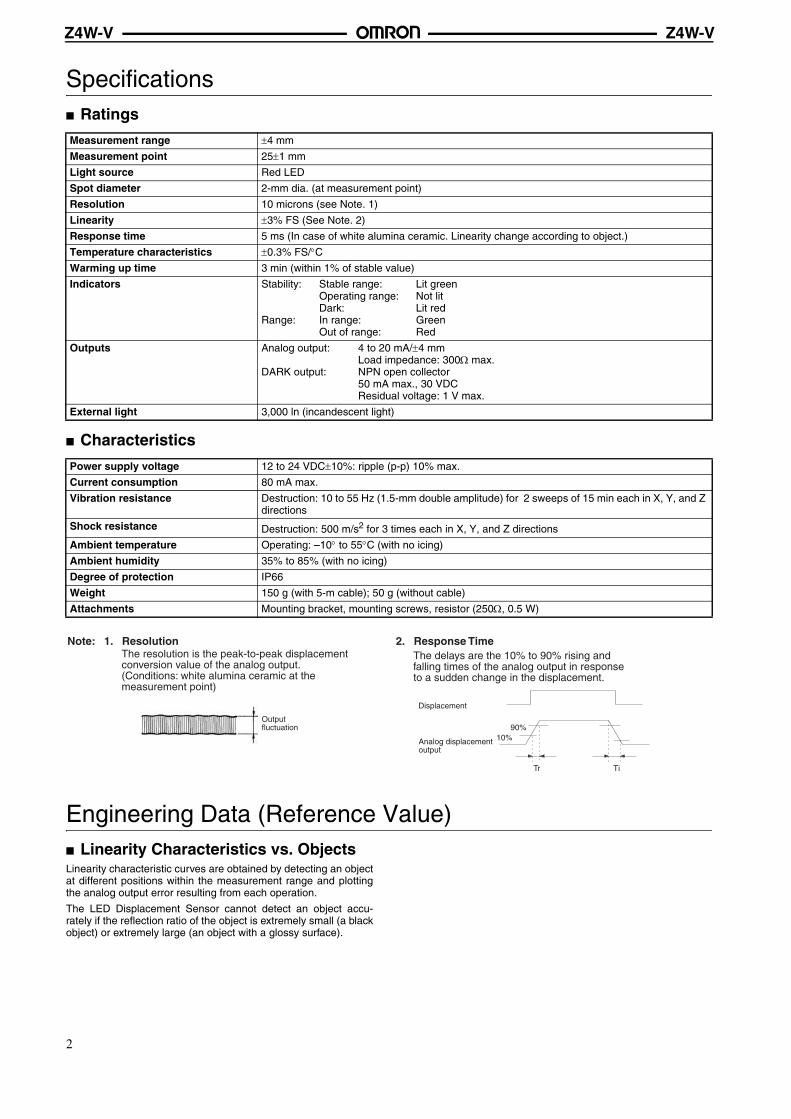
Engineering Data (Reference Value) Linearity Characteristics vs. ObjectsLinearity characteristic curves are obtained by detecting an objectat different positions within the measurement range and plottingthe analog output error resulting from each operation.
The LED Displacement Sensor cannot detect an object accu-rately if the reflection ratio of the object is extremely small (a blackobject) or extremely large (an object with a glossy surface).
Measurement range ±4 mm
Measurement point 25±1 mm
Light source Red LED
Spot diameter 2-mm dia. (at measurement point)
Resolution 10 microns (see Note. 1)
Linearity ±3% FS (See Note. 2)
Response time 5 ms (In case of white alumina ceramic. Linearity change according to object.)
Temperature characteristics ±0.3% FS/°CWarming up time 3 min (within 1% of stable value)
Indicators Stability: Stable range: Lit greenOperating range: Not litDark: Lit red
Range: In range: GreenOut of range: Red
Outputs Analog output: 4 to 20 mA/±4 mmLoad impedance: 300Ω max.
DARK output: NPN open collector50 mA max., 30 VDCResidual voltage: 1 V max.
External light 3,000 ln (incandescent light)
Power supply voltage 12 to 24 VDC±10%: ripple (p-p) 10% max.
Current consumption 80 mA max.
Vibration resistance Destruction: 10 to 55 Hz (1.5-mm double amplitude) for 2 sweeps of 15 min each in X, Y, and Z directions
Shock resistance Destruction: 500 m/s2 for 3 times each in X, Y, and Z directions
Ambient temperature Operating: –10° to 55°C (with no icing)
Ambient humidity 35% to 85% (with no icing)
Degree of protection IP66
Weight 150 g (with 5-m cable); 50 g (without cable)
Attachments Mounting bracket, mounting screws, resistor (250Ω, 0.5 W)
Note: 1. Resolution
Displacement
90%10%
Tr Ti
2. Response TimeThe resolution is the peak-to-peak displacement conversion value of the analog output. (Conditions: white alumina ceramic at the measurement point)
Output fluctuation
The delays are the 10% to 90% rising and falling times of the analog output in response to a sudden change in the displacement.
Analog displacement output
2
Z4W-VZ4W-V
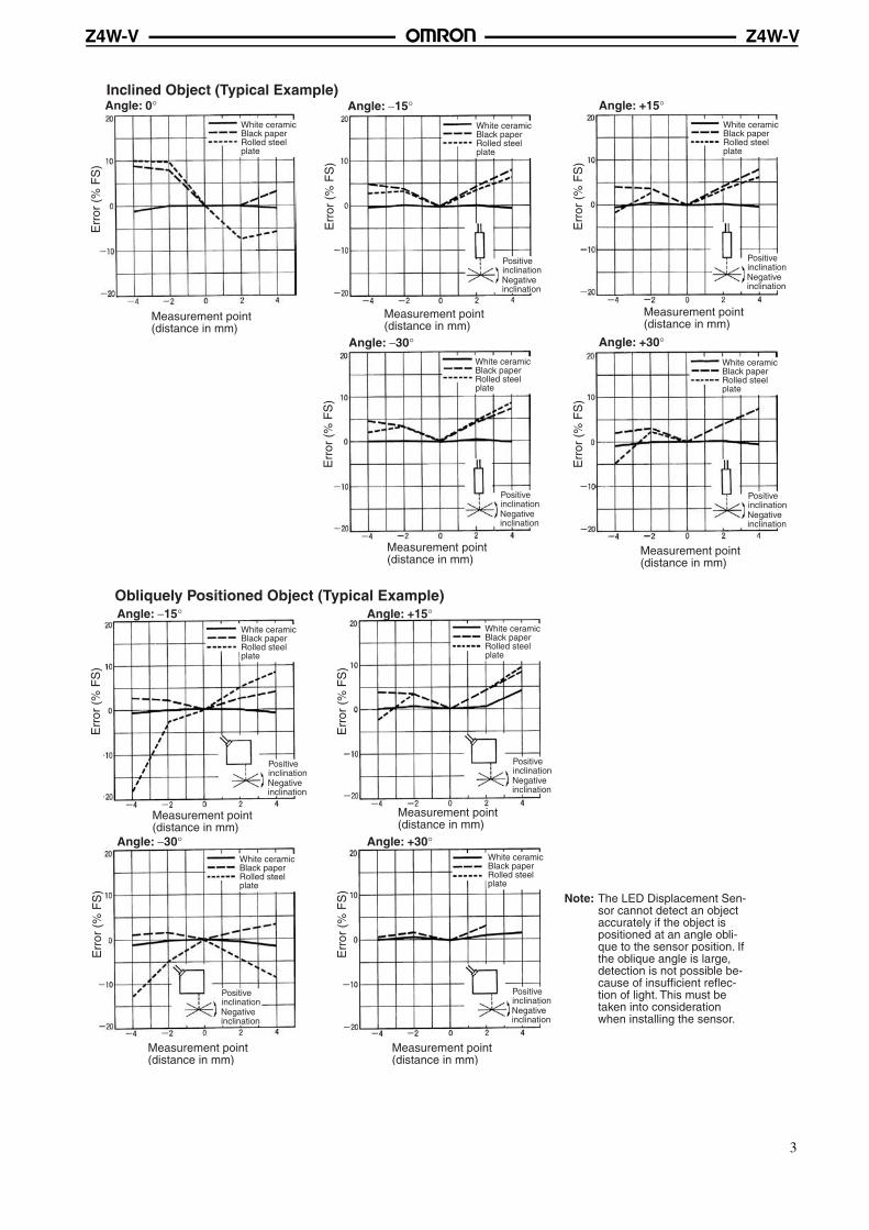
Inclined Object (Typical Example)
Err
or (
% F
S)
Angle: −15° Angle: +15°
Err
or (
% F
S)
Err
or (
% F
S)
Err
or (
% F
S)
Angle: −30° Angle: +30°
Angle: 0°E
rror
(%
FS
)
White ceramic Black paper Rolled steel plate
Measurement point (distance in mm)
White ceramic Black paper Rolled steel plate
White ceramic Black paper Rolled steel plate
White ceramic Black paper Rolled steel plate
White ceramic Black paper Rolled steel plate
Positive inclinationNegative inclination
Positive inclinationNegative inclination
Positive inclinationNegative inclination
Positive inclinationNegative inclination
Measurement point (distance in mm)
Measurement point (distance in mm)
Measurement point (distance in mm)
Measurement point (distance in mm)
Obliquely Positioned Object (Typical Example)
Err
or (
% F
S)
Angle: −15° Angle: +15°
Err
or (
% F
S)
Err
or (
% F
S)
Err
or (
% F
S)
Angle: −30° Angle: +30°
White ceramic Black paper Rolled steel plate
Positive inclinationNegative inclination
Measurement point (distance in mm)
Measurement point (distance in mm)
Measurement point (distance in mm)
Measurement point (distance in mm)
White ceramic Black paper Rolled steel plate
White ceramic Black paper Rolled steel plate
White ceramic Black paper Rolled steel plate
Positive inclinationNegative inclination
Positive inclinationNegative inclination
Positive inclinationNegative inclination
Note: The LED Displacement Sen-sor cannot detect an object accurately if the object is positioned at an angle obli-que to the sensor position. If the oblique angle is large, detection is not possible be-cause of insufficient reflec-tion of light. This must be taken into consideration when installing the sensor.
3
Z4W-VZ4W-V
Sensing Various Objects
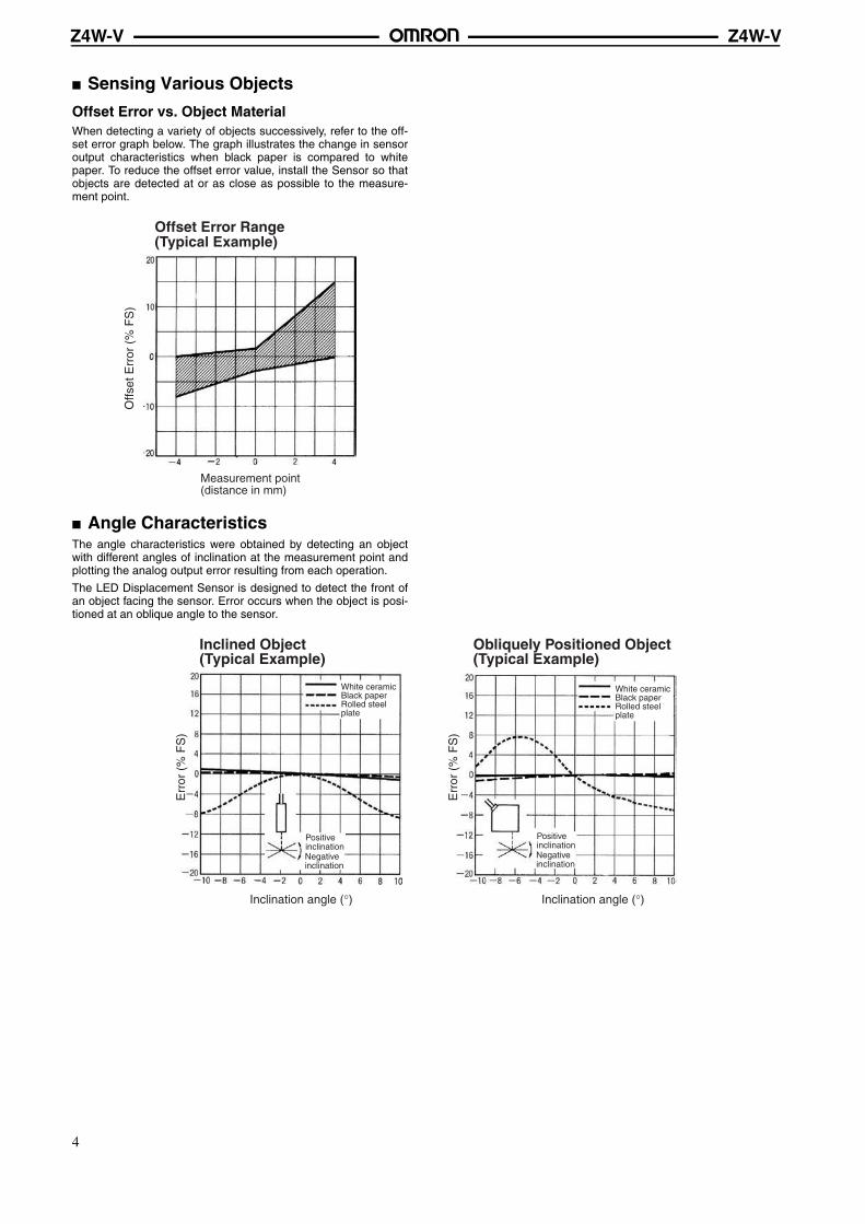
Offset Error vs. Object MaterialWhen detecting a variety of objects successively, refer to the off-set error graph below. The graph illustrates the change in sensoroutput characteristics when black paper is compared to whitepaper. To reduce the offset error value, install the Sensor so thatobjects are detected at or as close as possible to the measure-ment point.
Angle CharacteristicsThe angle characteristics were obtained by detecting an objectwith different angles of inclination at the measurement point andplotting the analog output error resulting from each operation.
The LED Displacement Sensor is designed to detect the front ofan object facing the sensor. Error occurs when the object is posi-tioned at an oblique angle to the sensor.
Offs
et E
rror
(%
FS
)
Measurement point (distance in mm)
Offset Error Range (Typical Example)
Inclined Object (Typical Example)
Inclination angle (°)
Err
or (
% F
S)
Obliquely Positioned Object(Typical Example)
Err
or (
% F
S)
Inclination angle (°)
White ceramic Black paper Rolled steel plate
Positive inclinationNegative inclination
White ceramic Black paper Rolled steel plate
Positive inclinationNegative inclination
4
Z4W-VZ4W-V
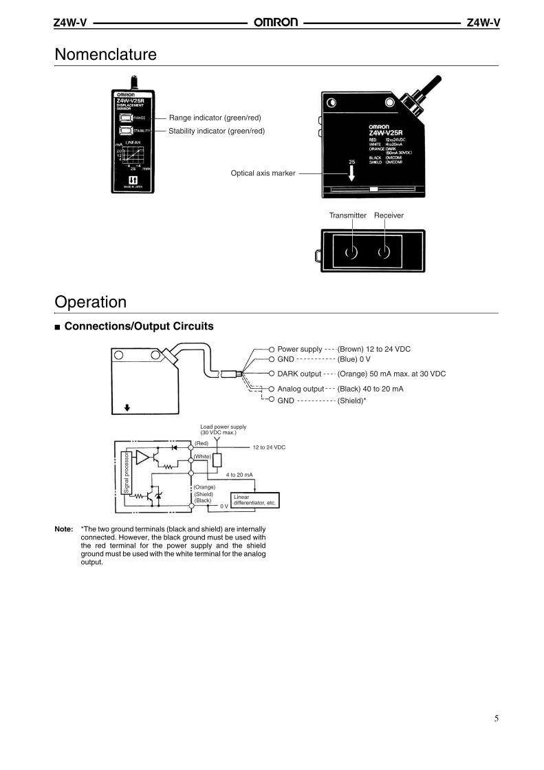
Nomenclature
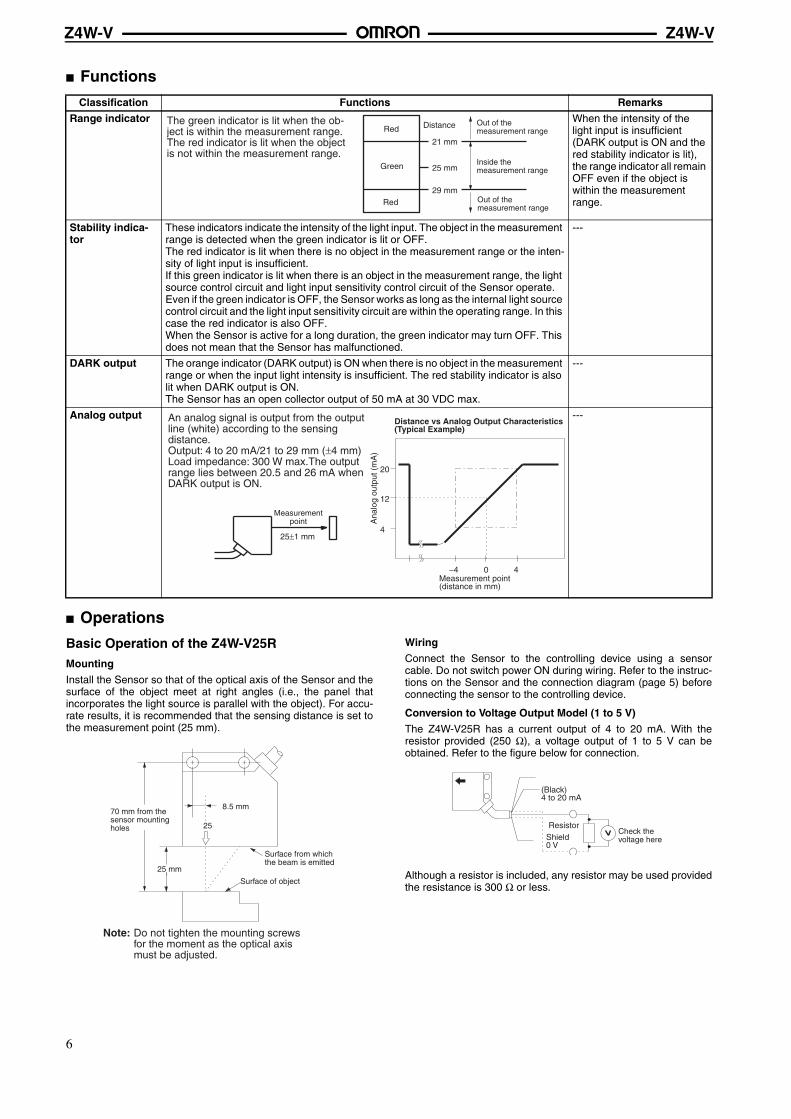
Operation Connections/Output Circuits
Note: *The two ground terminals (black and shield) are internallyconnected. However, the black ground must be used withthe red terminal for the power supply and the shieldground must be used with the white terminal for the analogoutput.
Range indicator (green/red)
Stability indicator (green/red)
Optical axis marker
Transmitter Receiver
Power supply (Brown) 12 to 24 VDCGND (Blue) 0 V
DARK output (Orange) 50 mA max. at 30 VDC
Analog output (Black) 40 to 20 mA
GND (Shield)*
12 to 24 VDC
4 to 20 mA
0 V
(Red)
(White)
(Shield)(Black)
Sig
nal p
roce
ssor
(Orange)
Load power supply (30 VDC max.)
Linear differentiator, etc.
5
Z4W-VZ4W-V
Functions
Operations
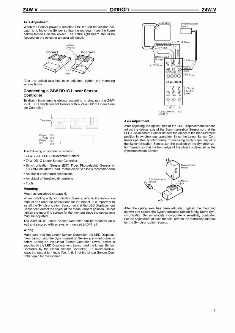
Basic Operation of the Z4W-V25RMounting
Install the Sensor so that of the optical axis of the Sensor and thesurface of the object meet at right angles (i.e., the panel thatincorporates the light source is parallel with the object). For accu-rate results, it is recommended that the sensing distance is set tothe measurement point (25 mm).
Wiring
Connect the Sensor to the controlling device using a sensorcable. Do not switch power ON during wiring. Refer to the instruc-tions on the Sensor and the connection diagram (page 5) beforeconnecting the sensor to the controlling device.
Conversion to Voltage Output Model (1 to 5 V)
The Z4W-V25R has a current output of 4 to 20 mA. With theresistor provided (250 Ω), a voltage output of 1 to 5 V can beobtained. Refer to the figure below for connection.
Although a resistor is included, any resistor may be used providedthe resistance is 300 Ω or less.
Classification Functions Remarks
Range indicator When the intensity of the light input is insufficient (DARK output is ON and the red stability indicator is lit), the range indicator all remain OFF even if the object is within the measurement range.
Stability indica-tor
These indicators indicate the intensity of the light input. The object in the measurement range is detected when the green indicator is lit or OFF.The red indicator is lit when there is no object in the measurement range or the inten-sity of light input is insufficient.If this green indicator is lit when there is an object in the measurement range, the light source control circuit and light input sensitivity control circuit of the Sensor operate.Even if the green indicator is OFF, the Sensor works as long as the internal light source control circuit and the light input sensitivity circuit are within the operating range. In this case the red indicator is also OFF.When the Sensor is active for a long duration, the green indicator may turn OFF. This does not mean that the Sensor has malfunctioned.
---
DARK output The orange indicator (DARK output) is ON when there is no object in the measurement range or when the input light intensity is insufficient. The red stability indicator is also lit when DARK output is ON.The Sensor has an open collector output of 50 mA at 30 VDC max.
---
Analog output ---
21 mm
25 mm
29 mm
Red
Green
Red
DistanceThe green indicator is lit when the ob-ject is within the measurement range. The red indicator is lit when the object is not within the measurement range.
Out of the measurement range
Inside the measurement range
Out of the measurement range
Distance vs Analog Output Characteristics (Typical Example)
Ana
log
outp
ut (
mA
)
Measurement point(distance in mm)
20
12
4
−4 0 4
25±1 mm
An analog signal is output from the output line (white) according to the sensing distance.Output: 4 to 20 mA/21 to 29 mm (±4 mm)Load impedance: 300 W max.The output range lies between 20.5 and 26 mA when DARK output is ON.
Measurement point
25 mm
8.5 mm
25
Surface of object
Note: Do not tighten the mounting screws for the moment as the optical axis must be adjusted.
70 mm from the sensor mounting holes
Surface from which the beam is emitted
(Black)4 to 20 mA
ResistorShield0 V
Check the voltage here
6
Z4W-VZ4W-V
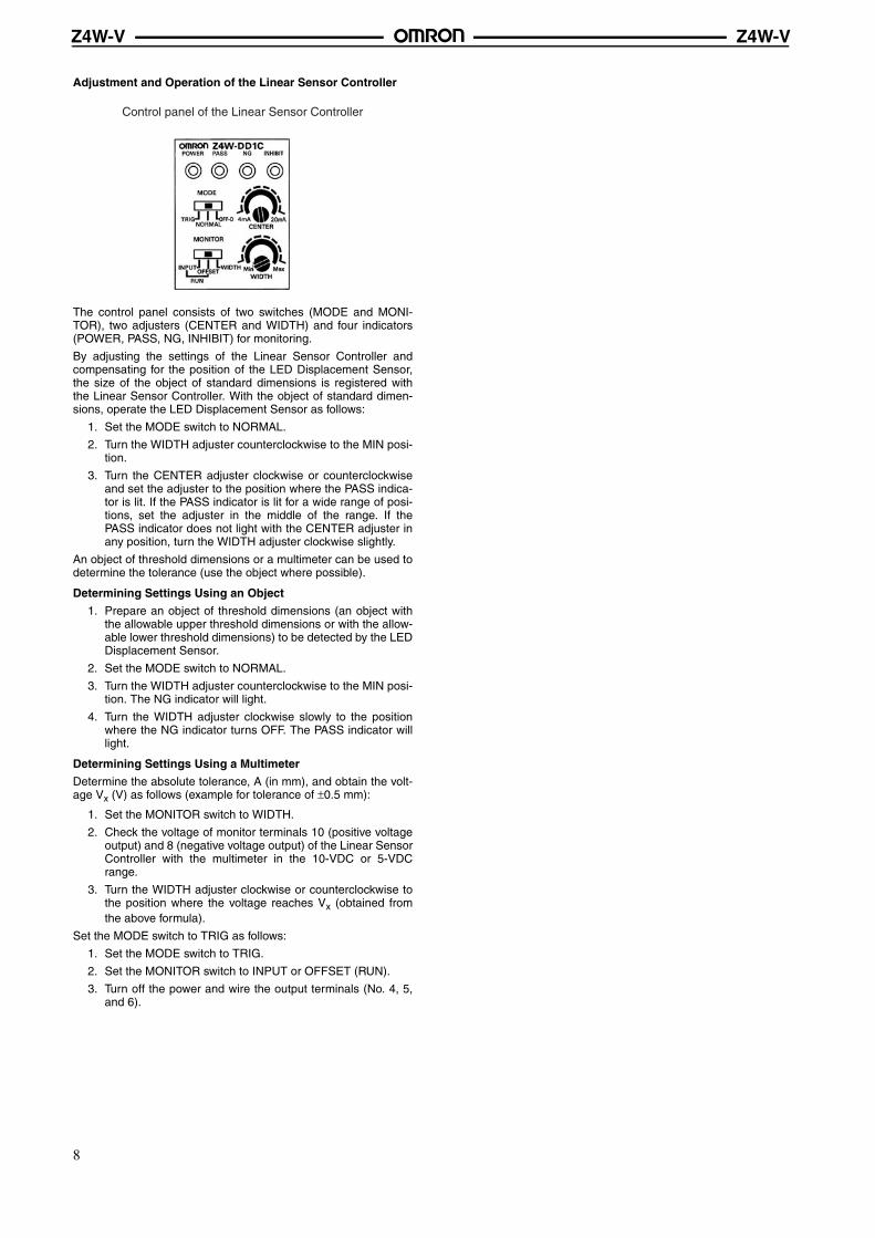
Axis Adjustment
When the Sensor power is switched ON, the red transmitter indi-cator is lit. Move the Sensor so that the red beam (see the figurebelow) focuses on the object. The entire light beam should befocused on the object or an error will result.
After the optical axis has been adjusted, tighten the mountingscrews firmly.
Connecting a Z4W-DD1C Linear Sensor ControllerTo discriminate among objects according to size, use the Z4W-V25R LED Displacement Sensor with a Z4W-DD1C Linear Sen-sor Controller.
The following equipment is required:
• Z4W-V25R LED Displacement Sensor
• Z4W-DD1C Linear Sensor Controller
• Synchronization Sensor (E3X Fiber Photoelectric Sensor orE3C-VM Miniature Head Photoelectric Sensor is recommended)
• An object of standard dimensions
• An object of threshold dimensions
• Tools
Mounting
Mount as described on page 6.
When installing a Synchronization Sensor, refer to the instructionmanual and read the precautions for the model. It is important toinstall the Synchronization Sensor so that the LED DisplacementSensor can detect the object at the measurement position. Do nottighten the mounting screws for the moment since the optical axismust be adjusted.
The Z4W-DD1C Linear Sensor Controller can be mounted on awall and secured with screws, or mounted to DIN rail.
Wiring
Make sure that the Linear Sensor Controller, the LED Displace-ment Sensor, and the Synchronization Sensor are wired correctlybefore turning on the Linear Sensor Controller power (power issupplied to the LED Displacement Sensor and the Linear SensorController by the Linear Sensor Controller). To avoid trouble,leave the output terminals (No. 4, 5, 6) of the Linear Sensor Con-troller open for the moment.
Axis Adjustment
After adjusting the optical axis of the LED Displacement Sensor,adjust the optical axis of the Synchronization Sensor so that theLED Displacement Sensor detects the object at the measurementposition in synchronous operation. Since the Linear Sensor Con-troller operates synchronously on receiving each output signal ofthe Synchronization Sensor, set the position of the Synchroniza-tion Sensor so that the front edge of the object is detected by theSynchronization Sensor.
After the optical axis has been adjusted, tighten the mountingscrews and secure the Synchronization Sensor firmly. Some Syn-chronization Sensor models incorporate a sensitivity controller.For the adjustment of such models, refer to the instruction manualfor the Synchronization Sensor.
Spot
Correct Incorrect
Surface of object
Tolerance
Output
Output NG
ONOFFONOFF
PASS
Z4W-DD1C
Z4W-V25R
4 to 20 mA Black
0 V
+12 V 0 V 4 to 20 mA
FG100 to 240 VAC 50/60Hz
+12 V Brown
DARK output Orange
0 V Blue
Shi
eld
0 V Blue
OutputBlack
12 V Brown
Synchronization sensor
100 mA 30 VDC Max.
Displacement sensor
Synchronization sensor Surface of
object
7
Z4W-VZ4W-V
Adjustment and Operation of the Linear Sensor Controller
The control panel consists of two switches (MODE and MONI-TOR), two adjusters (CENTER and WIDTH) and four indicators(POWER, PASS, NG, INHIBIT) for monitoring.
By adjusting the settings of the Linear Sensor Controller andcompensating for the position of the LED Displacement Sensor,the size of the object of standard dimensions is registered withthe Linear Sensor Controller. With the object of standard dimen-sions, operate the LED Displacement Sensor as follows:
1. Set the MODE switch to NORMAL.
2. Turn the WIDTH adjuster counterclockwise to the MIN posi-tion.
3. Turn the CENTER adjuster clockwise or counterclockwiseand set the adjuster to the position where the PASS indica-tor is lit. If the PASS indicator is lit for a wide range of posi-tions, set the adjuster in the middle of the range. If thePASS indicator does not light with the CENTER adjuster inany position, turn the WIDTH adjuster clockwise slightly.
An object of threshold dimensions or a multimeter can be used todetermine the tolerance (use the object where possible).
Determining Settings Using an Object
1. Prepare an object of threshold dimensions (an object withthe allowable upper threshold dimensions or with the allow-able lower threshold dimensions) to be detected by the LEDDisplacement Sensor.
2. Set the MODE switch to NORMAL.
3. Turn the WIDTH adjuster counterclockwise to the MIN posi-tion. The NG indicator will light.
4. Turn the WIDTH adjuster clockwise slowly to the positionwhere the NG indicator turns OFF. The PASS indicator willlight.
Determining Settings Using a Multimeter
Determine the absolute tolerance, A (in mm), and obtain the volt-age Vx (V) as follows (example for tolerance of ±0.5 mm):
1. Set the MONITOR switch to WIDTH.
2. Check the voltage of monitor terminals 10 (positive voltageoutput) and 8 (negative voltage output) of the Linear SensorController with the multimeter in the 10-VDC or 5-VDCrange.
3. Turn the WIDTH adjuster clockwise or counterclockwise tothe position where the voltage reaches Vx (obtained fromthe above formula).
Set the MODE switch to TRIG as follows:
1. Set the MODE switch to TRIG.
2. Set the MONITOR switch to INPUT or OFFSET (RUN).
3. Turn off the power and wire the output terminals (No. 4, 5,and 6).
Control panel of the Linear Sensor Controller
8
Z4W-VZ4W-V
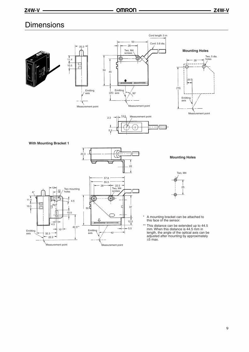
Dimensions
Mounting Holes20.3
11.4
10.5
Measurement point
28550
5045
(25)
Measurement point
Cord length: 5 m
Cord: 3.8 dia.
30°
13.52.3
5.3
Measurement point
28
(8.5)
(70)
Measurement point
Two, M4 screws
Emitting axis
Emitting axis
Emitting axis
Two, 5 dia. holes
Mounting Holes
With Mounting Bracket 1
Two, M4
25
A*
11.4
10.5
1212
4.5
10.5
R27
4.5
10
32.322.2
42.5**
Measurement point
42
5.5
12.5
3750
28 22.555.5
57.8
22
20.3
Measurement point
* A mounting bracket can be attached to this face of the sensor.
** This distance can be extended up to 44.5 mm. When this distance is 44.5 mm in length, the angle of the optical axis can be adjusted after mounting by approximately ±5 max.
Two mounting holes
Two, M4 screws
Emitting axis
Emitting axis
9
Z4W-VZ4W-V
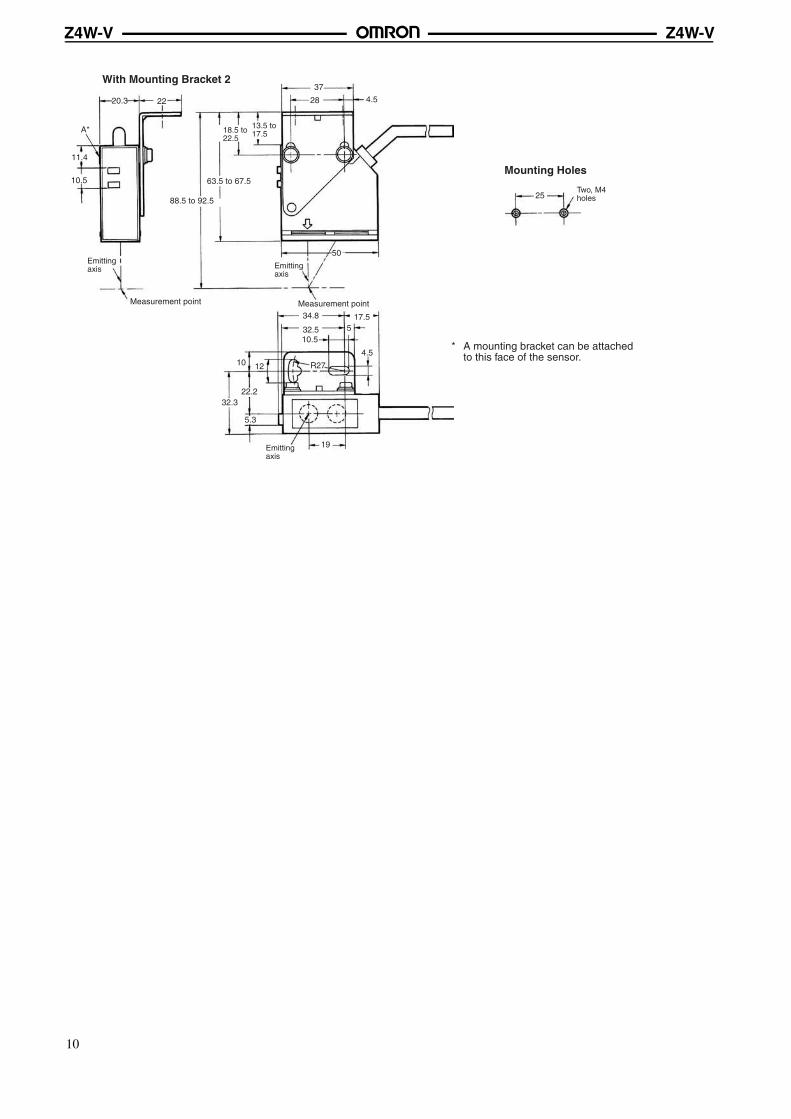
Mounting Holes
With Mounting Bracket 2
Measurement point
A*
11.4
10.5
20.3 22
63.5 to 67.5
88.5 to 92.5
37
28 4.5
50
32.322.2
10 12
5.3
19
4.5
17.55
34.8
32.510.5
R27
Measurement point
25
* A mounting bracket can be attached to this face of the sensor.
Two, M4 holes
Emitting axis Emitting
axis
13.5 to 17.518.5 to
22.5
Emitting axis
10
Z4W-VZ4W-V
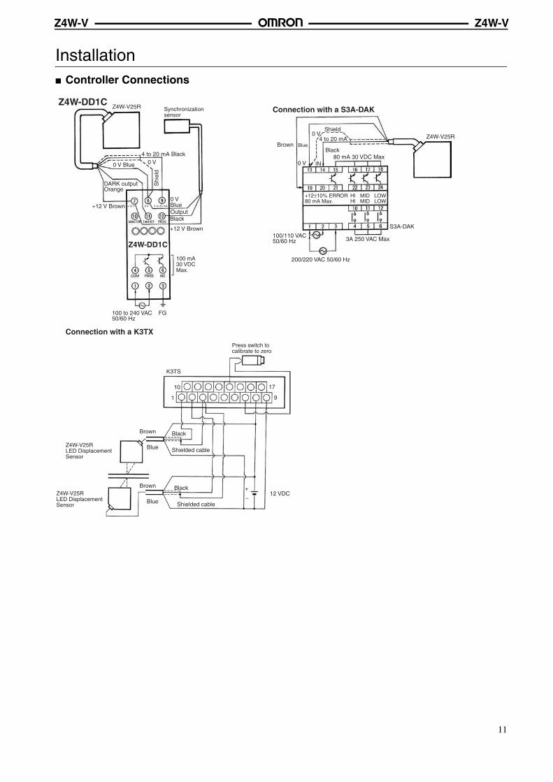
Installation Controller Connections
Z4W-DD1CConnection with a S3A-DAK
Connection with a K3TX
0 V Blue 0 V
DARK output Orange
+12 V Brown
+12 V Brown
0 V BlueOutput Black
+12 V 0 V 4 to 20 mA
FG100 to 240 VAC 50/60 Hz
Z4W-V25R
4 to 20 mA Black
Z4W-DD1C
Shi
eld
Shield0 V
4 to 20 mA
0 V IN
BrownBlack
Blue
80 mA 30 VDC Max
3A 250 VAC Max
S3A-DAK
200/220 VAC 50/60 Hz
100/110 VAC 50/60 Hz
HI MID LOWHI MID LOW
+12±10% ERROR 80 mA Max.
Z4W-V25R
K3TS
Brown Black
Blue Shielded cable
12 VDC
10
1
17
9
+
−
Brown Black
Blue Shielded cable
Synchronization sensor
100 mA 30 VDC Max.
Press switch to calibrate to zero
Z4W-V25R LED Displacement Sensor
Z4W-V25R LED Displacement Sensor
11
Z4W-VZ4W-V
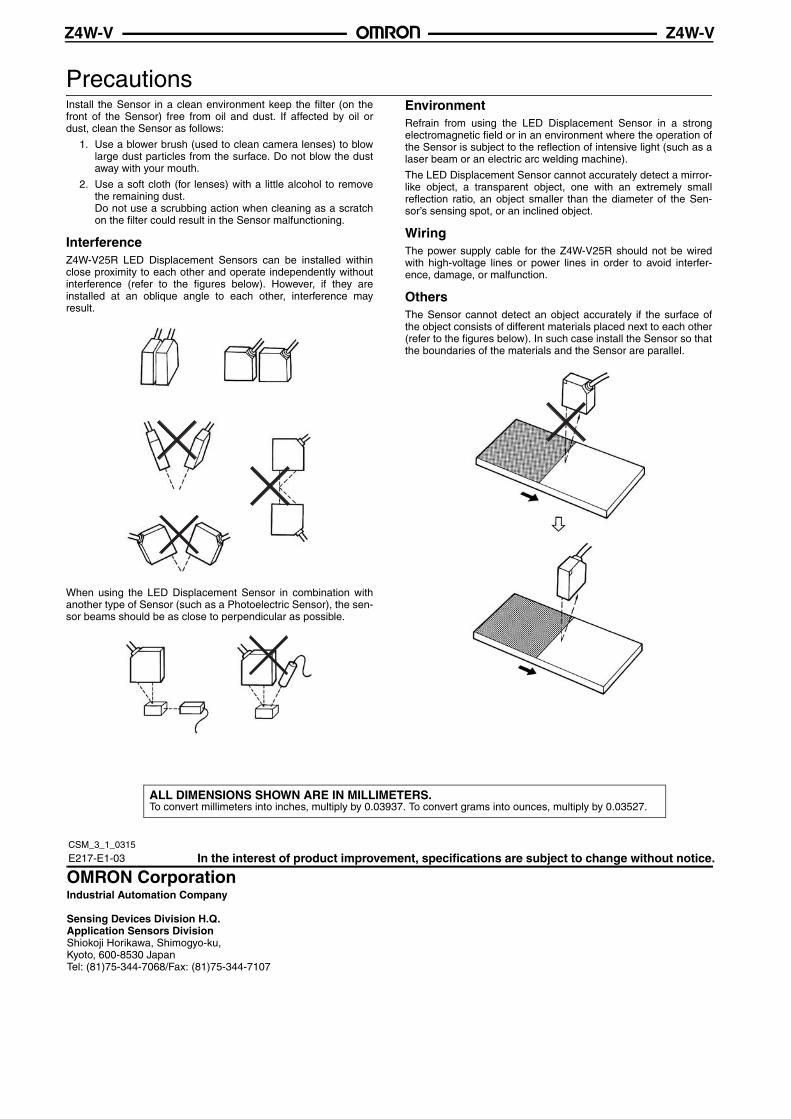
PrecautionsInstall the Sensor in a clean environment keep the filter (on thefront of the Sensor) free from oil and dust. If affected by oil ordust, clean the Sensor as follows:
1. Use a blower brush (used to clean camera lenses) to blowlarge dust particles from the surface. Do not blow the dustaway with your mouth.
2. Use a soft cloth (for lenses) with a little alcohol to removethe remaining dust.Do not use a scrubbing action when cleaning as a scratchon the filter could result in the Sensor malfunctioning.
InterferenceZ4W-V25R LED Displacement Sensors can be installed withinclose proximity to each other and operate independently withoutinterference (refer to the figures below). However, if they areinstalled at an oblique angle to each other, interference mayresult.
When using the LED Displacement Sensor in combination withanother type of Sensor (such as a Photoelectric Sensor), the sen-sor beams should be as close to perpendicular as possible.
EnvironmentRefrain from using the LED Displacement Sensor in a strongelectromagnetic field or in an environment where the operation ofthe Sensor is subject to the reflection of intensive light (such as alaser beam or an electric arc welding machine).
The LED Displacement Sensor cannot accurately detect a mirror-like object, a transparent object, one with an extremely smallreflection ratio, an object smaller than the diameter of the Sen-sor’s sensing spot, or an inclined object.
WiringThe power supply cable for the Z4W-V25R should not be wiredwith high-voltage lines or power lines in order to avoid interfer-ence, damage, or malfunction.
OthersThe Sensor cannot detect an object accurately if the surface ofthe object consists of different materials placed next to each other(refer to the figures below). In such case install the Sensor so thatthe boundaries of the materials and the Sensor are parallel.
In the interest of product improvement, specifications are subject to change without notice.
ALL DIMENSIONS SHOWN ARE IN MILLIMETERS.To convert millimeters into inches, multiply by 0.03937. To convert grams into ounces, multiply by 0.03527.
E217-E1-03
OMRON CorporationIndustrial Automation Company
Sensing Devices Division H.Q.Application Sensors DivisionShiokoji Horikawa, Shimogyo-ku,Kyoto, 600-8530 JapanTel: (81)75-344-7068/Fax: (81)75-344-7107
CSM_3_1_0315
Related Documents