Welcome message from author
This document is posted to help you gain knowledge. Please leave a comment to let me know what you think about it! Share it to your friends and learn new things together.
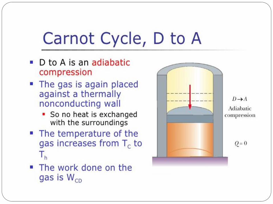
Transcript
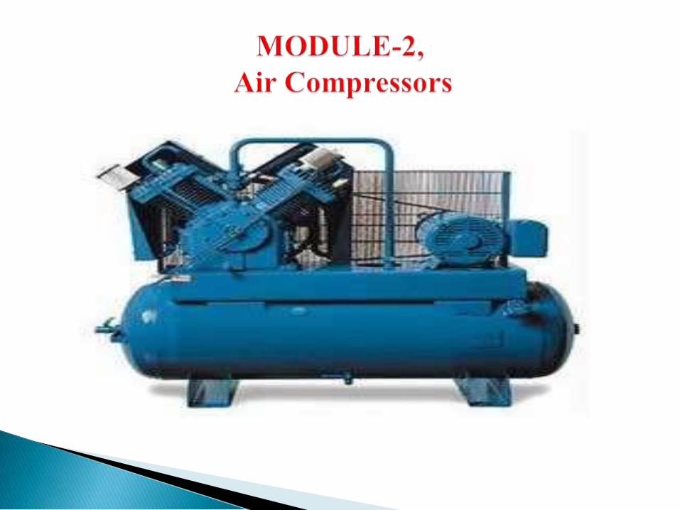
The function of air compressor is to take a definite quantity of fluid (gas
/air) and deliver it at a required pressure.
A basic pneumatic system consist of a source of compressed air, control
valves, pipelines & pipe fittings and pneumatic accessories like filter,
regulator and lubricator
For operating pneumatic tools such as drills, screw drivers,
hammers, chisels
For pneumatic cranes
For pneumatic brakes of automobiles, railways and presses
For agricultural accessories such as dusters and sprayers

For drive of CNC machine tools
For pneumatic conveying of materials
For pneumatic gauging, inspection and low cost automation
systems
An air compressor is a mechanical device that
increases the pressure of air by reducing volume.
Air is compressible, the compressor reduces the
volume of air and induces pressure in the air
An air compressor converts electrical energy into
kinetic energy in the form of the air
The compressed air is stored in the air receiver and
can be used for cleaning under pressure, generating
torque and develop force using actuators
This source is free of cost, safe, flexible and
convenient
Air compressor has very few parts hence
maintenance is very low
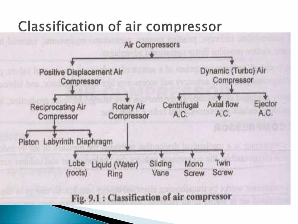
Air compressors are classified according to method
of energy transfer and pressure generation i.e.
positive displacement and dynamic compressors
Positive displacement compressors work on the
principle of increasing the pressure of air by reducing
the volume of air in an enclosed chamber
Dynamic compressors works on the principle of
imparting the energy by rotating vanes of impeller on
air flowing through casing that increases pressure in
air
According to number of stages
Single stage, double stage, three stage of multiple stage
According to action
Single acting or double acting
According to position of cylinder w.r.t. crankshaft
Cylinders inline, vertical, radial position, V-type
cylinder arrangement
According to prime mover
Electric motor drive or IC engine drive, Gas turbine
drives
According to cooling medium
Air cooled, water cooled air compressors

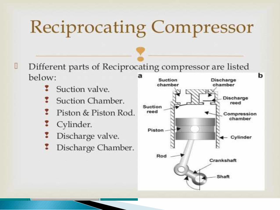

A reciprocating air compressor consist of a piston which is enclosed
withina cylinder andequippedwithsuctionanddischargevalve
Thepistonreceivespower fromelectricmotoror IC engine.
The compression of air is done by first drawing a volume of air into the
cylinder through suction valve during suction stroke of piston and then
compressedanddischarged throughdeliveryvalveduringdeliverystroke

Piston compressors, also called reciprocating compressors, use a
piston and cylinder arrangement to provide compressive force - like
combustion engines or piston pumps. The reciprocating motion of
the piston due to external power compresses the refrigerant inside
the cylinder. Piston compressors have a low initial cost and a
simple, easy to install design. They have a large power output
range and can reach extremely high pressures. However, they have
high maintenance costs, potential vibrational issues, and are not
typically designed to run continuously at full capacity.


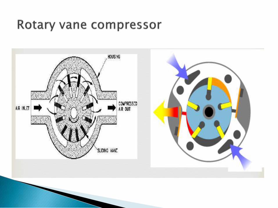
Rotary compressors have two rotating elements, like gears,
between which the refrigerant is compressed. These
compressors are very efficient because the actions of taking in
refrigerant and compressing refrigerant occur
simultaneously. They have very few moving parts, low
rotational speeds, low initial and maintenance costs, and are
forgiving in dirty environments. However, they are limited to
smaller volumes of the gas and produce less pressure than
other types of compressors.
The following diagram shows rotary vane compressor operatio

Screw compressors use a pair of helical rotors or screws which
mesh together to compress the refrigerant between them. They
can produce high pressure for a small quantity of gas
and consume less power than reciprocating compressors. They
have low to medium initial and maintenance costs and few
moving parts. However, they have difficulty in dirty
environments, high rotational speeds, and shorter life
expectancies than other designs.


It is dynamic compressor.
It consist of a rotating impeller which rotates at higher speed
(upto 60000 rpm)
An impeller fitted inside casing force the air to the rim of
impeller, increasing velocity of air.
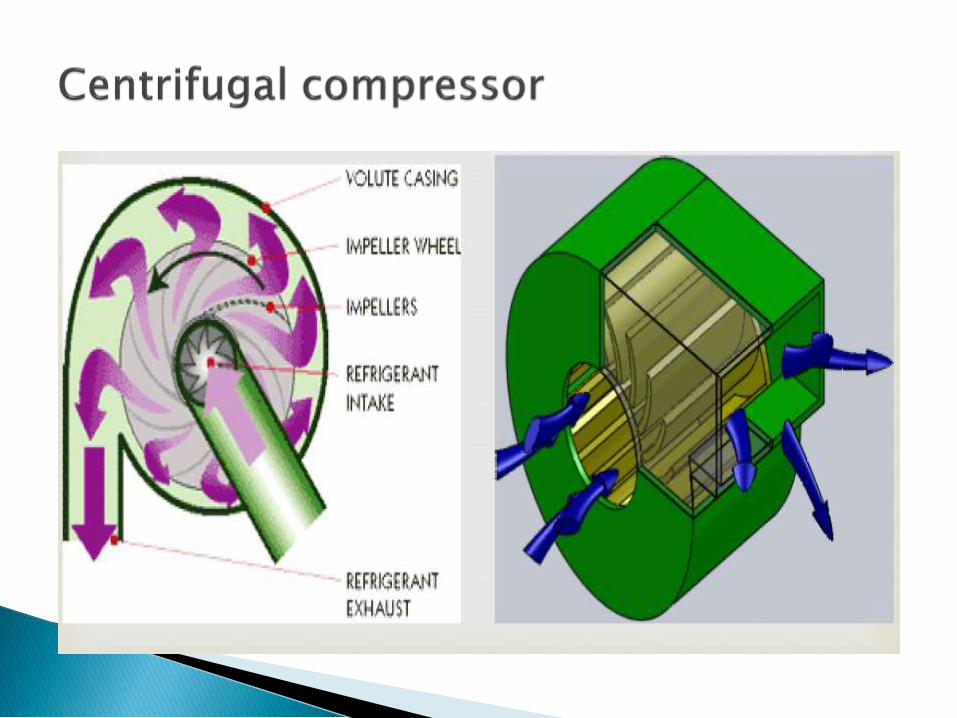

Centrifugal compressors use the rotating action of an impeller
wheel to exert centrifugal force on refrigerant inside a round
chamber (volute). Unlike other designs, centrifugal compressors
do not operate on the positive displacement principle, but have
fixed volume chambers. They are well suited to compressing
large volumes of refrigerant to relatively low pressures. The
compressive force generated by an impeller wheel is small,.
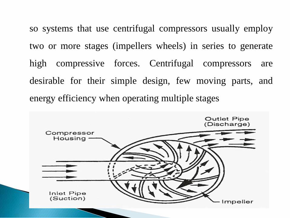
so systems that use centrifugal compressors usually employ
two or more stages (impellers wheels) in series to generate
high compressive forces. Centrifugal compressors are
desirable for their simple design, few moving parts, and
energy efficiency when operating multiple stages

Module -4
Power transmission

I t defined as the movement of energy from its place of generation to a
location where it is applied to perform useful work
Types of power transmission
➢Belt drive
➢Rope drive
➢Chain drive
➢Gear drive.
Power transmission

Belt drive
Selection of belt drive.➢ speed of the driving and driven shaft.➢Power to be transmitted.➢Space available➢Speed reduction ratio.➢Center distance between two shaft.
Types of belt drive
❑ light drive-it use to transmit small powers i.e 10 m/s ex.
Agriculture m/c and small m/c tools
❑Medium Drives-it used to trans mit 10m/s to 22m/s ex.m/c
tool
❑Heavy drives-it used to transmit more then 22m/s
.compressor and generator
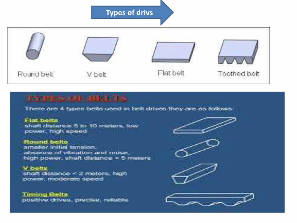
Types of drivs

Materials used
▪ leather belt
▪Cotton belt
▪Rubber belt
▪Balata belts
Types of flat belt drive
1-open belt drive
2- closed belt drive
3-Quarter turn belt drive
4-belt drive with idler pulleys
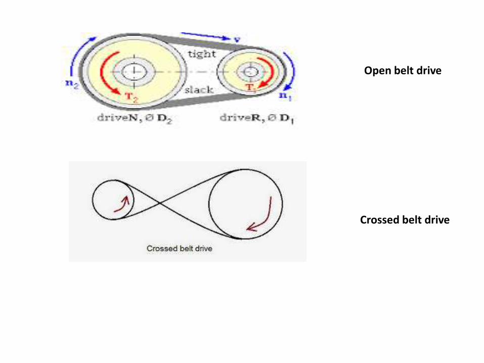
Open belt drive
Crossed belt drive

Quarter turn belt drive
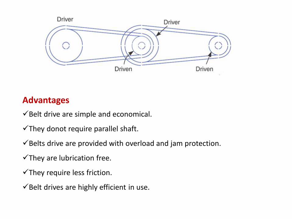
Advantages
✓Belt drive are simple and economical.
✓They donot require parallel shaft.
✓Belts drive are provided with overload and jam protection.
✓They are lubrication free.
✓They require less friction.
✓Belt drives are highly efficient in use.
Disadvantages
➢ belt drives angular velocity ratio is not necessary constant or equal
to the ratio of pulley diameters, because of slipping and stretching
➢Operating temperature are usually restricted to -35 to 85 c
➢Some adjustment of center distance between two shaft required.

Rope drive
Rope drive is used where a large amount of power is needed to transfer for
a long Distance (more then 8m) .the rope over a grooved pulley.
oFiber rope
➢It can use at a distance up to 60m.
➢It made from hemp ,manila or cotton
Advantages
Smooth and quiet , no precise alignment
required high efficiency
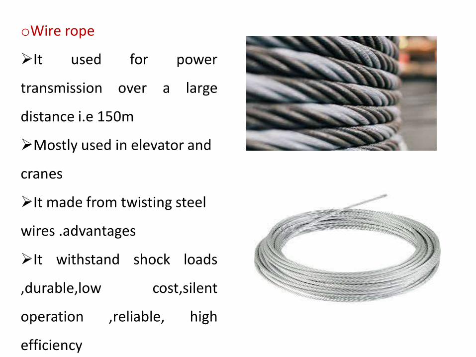
oWire rope
➢It used for power
transmission over a large
distance i.e 150m
➢Mostly used in elevator and
cranes
➢It made from twisting steel
wires .advantages
➢It withstand shock loads
,durable,low cost,silent
operation ,reliable, high
efficiency
Advantages of rope drives
✓Significant power transmission
✓It can be used for long distance
✓Ropes are strong and flexible
✓Provides smooth and quiet operation
✓It can run any direction
✓Low cost and economic
Disadvantages
✓Internal failure of the rope has no sign on external
✓Corrosion of wire
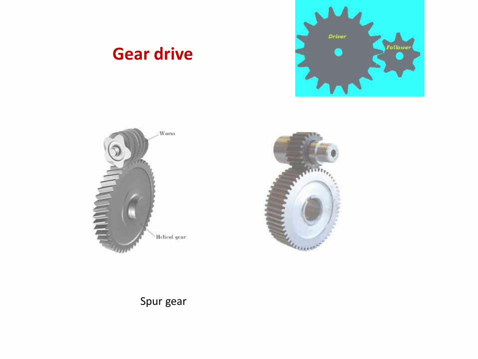
Gear drive
Spur gear
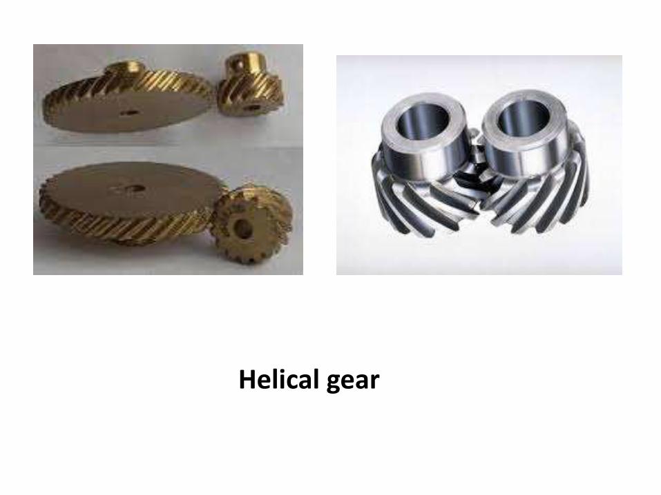
Helical gear
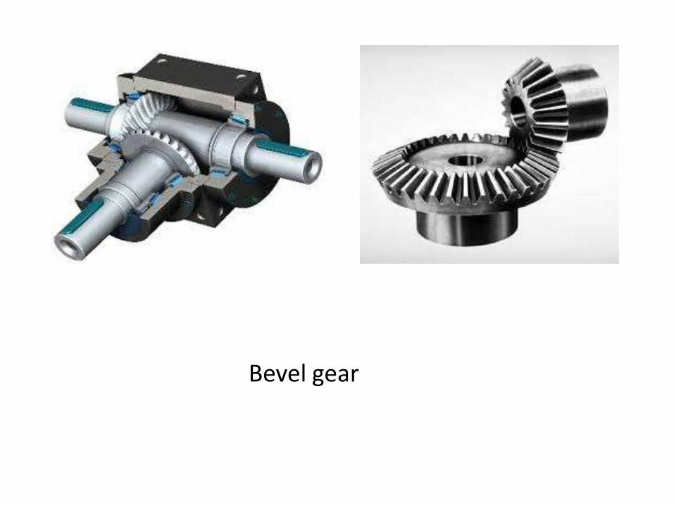
Bevel gear

Rack and pinion
Advantages
➢It transmits exact velocity ratio.
➢It may be used to transmit large power
➢It has high efficiency
➢It has reliable service
➢It has compact lay out
Disadvantages
➢The manufacture of gear required special tools and equipment
➢The error in cutting teeth may cause vibrations and noise
during operation.
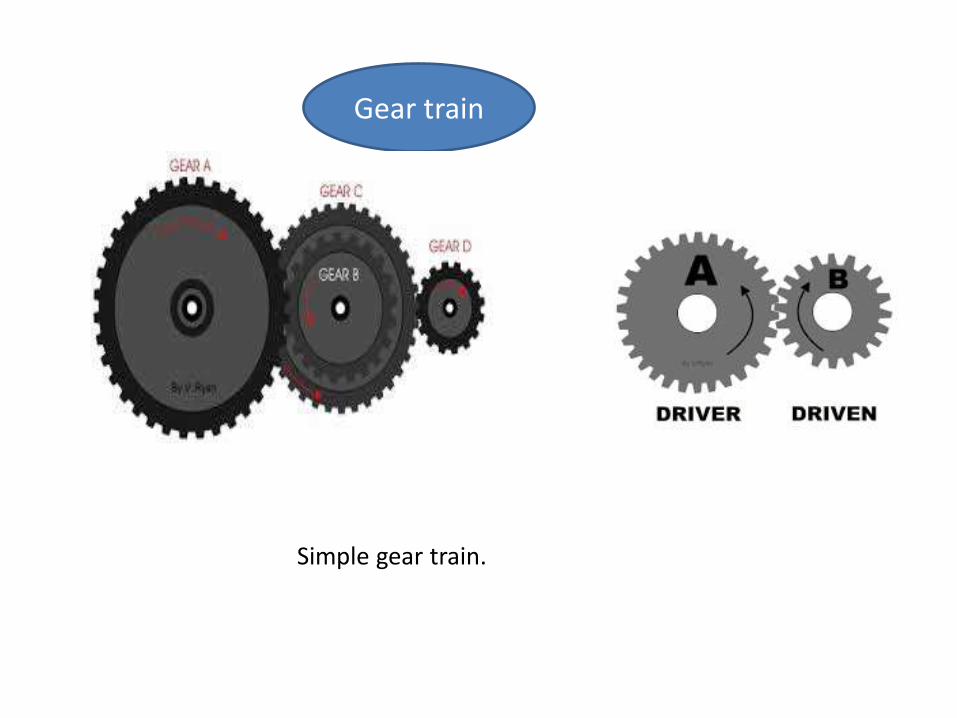
Gear train
Simple gear train.
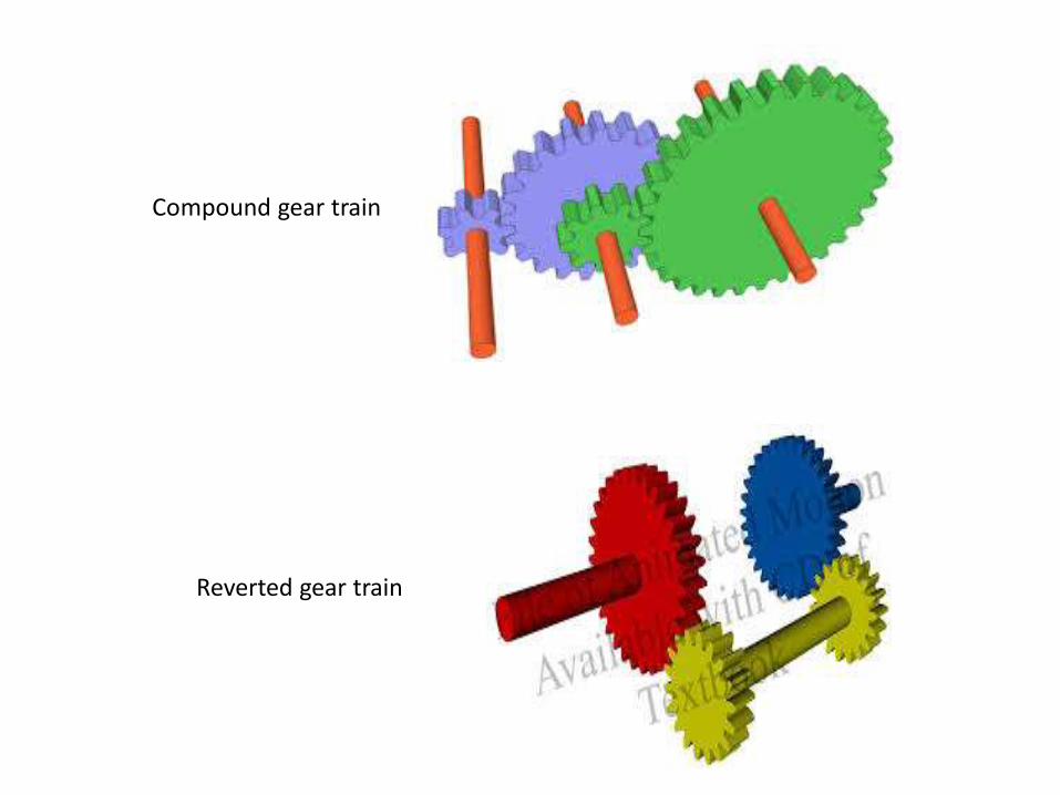
Compound gear train
Reverted gear train

An epicyclic gear train consists of two gears mounted so
that the center of one gear revolves around the center of
the other. A carrier connects the centers of the two
gears and rotates to carry one gear, called the planet gear,
around the other, called the sun gear.

BRAKING
SYSTEMS
BRAKE❖ The device used to stop any vehicle by applying
frictional forces.
❖ One of most important control componants of
vehicle.
❖ They are required to stop vehicle within smallest
possible distance.
❖ This is done by converting kinetic energy of vehicle
into heat energy which is dissipated into atmosphere.
BRAKING
REQUIREMENTS
1. Brakes must be strong enough to stop vehicle
with in a minimum distance in an emergency.
2. Brakes must have good antifade characterstics
i.e. their effectiveness should not decrease with
prolonged application. This requirement
demands cooling of brakes should be very
efficient.
TYPES• The brakes of an automobile are classified
according to as :-
1. Purpose
2. Location
3. Construction
4. Method of actuation
5. Extra braking effort
• Purpose:- From this point of view Brakes are classified as
service or primary and parking or secondry brakes.
• Location:- From this point of view brakes are located at
wheels or at transmission.
• Construction:-From this point of brakes are drum brakes
and disc brakes.
• Method of actuation:- This criterion gives following brake
type :
a) Mechanical Brakes
b) Hydraullic Brakes
c) Electric Brakes
d) Vaccum Brakes
e) Air Brakes
f) By-wire Brakes

DRUM BRAKES Shoes press against a spinning surface. In this
system, that surface is called a drum.
Drum brakes have more parts than disc brakes
and are harder to service, but they are less
expensive to manufacture.
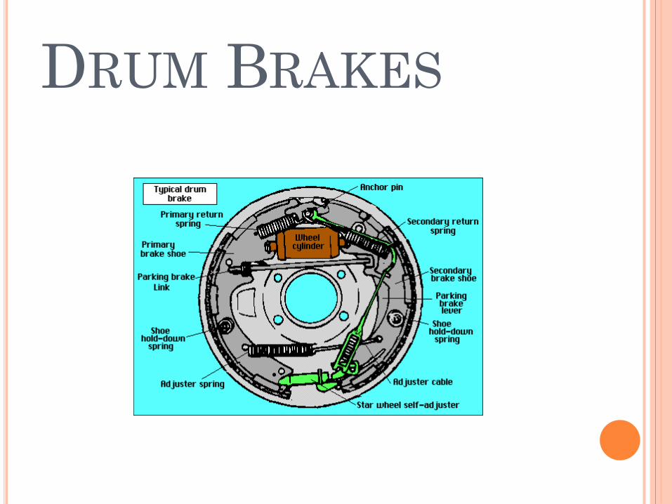
DRUM BRAKES
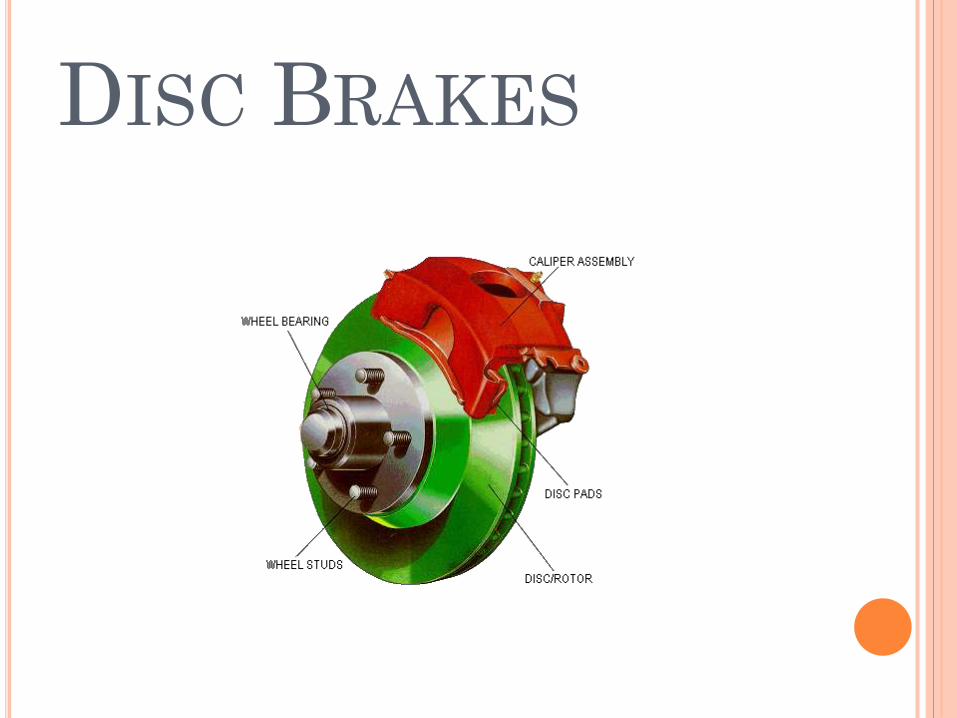
DISC BRAKES• A disc brake consists of a cast iron disc bolted to wheel
hub and stationary housing called calliper. Calliper is
connected to some stationary part of vehical like axle.
• When brakes are applied, piston move friction pads
into contact with disc, applying equal and opposite
force on disc.On releasing brakes, the rubber sealing
rings act as return springs and retract piston and
friction pads away from disc.
DISC BRAKES
MECHANICAL
BRAKES• Mechanical brakes are assemblies consisting of mechanical
elements for the slowing or stopping of vehicle. They use levers or linkages to transmit force from one point to another.
• There are several types of mechanical brakes. Band brakes, the simplest brake configuration, have a metal band lined with heat and wear resistant friction material. Drum brakes, which are commonly used on automobile rear wheels work when shoes press against a spinning surface called a drum. Disc breaks are constructed of brake pads, a caliper, and a rotor. During operation, the brake pads are squeezed against the rotor. Cone brakes are made with a cup and a cone, which is lined with heat and wear resistant material. During actuation, the cone is pressed against the mating cup surface.
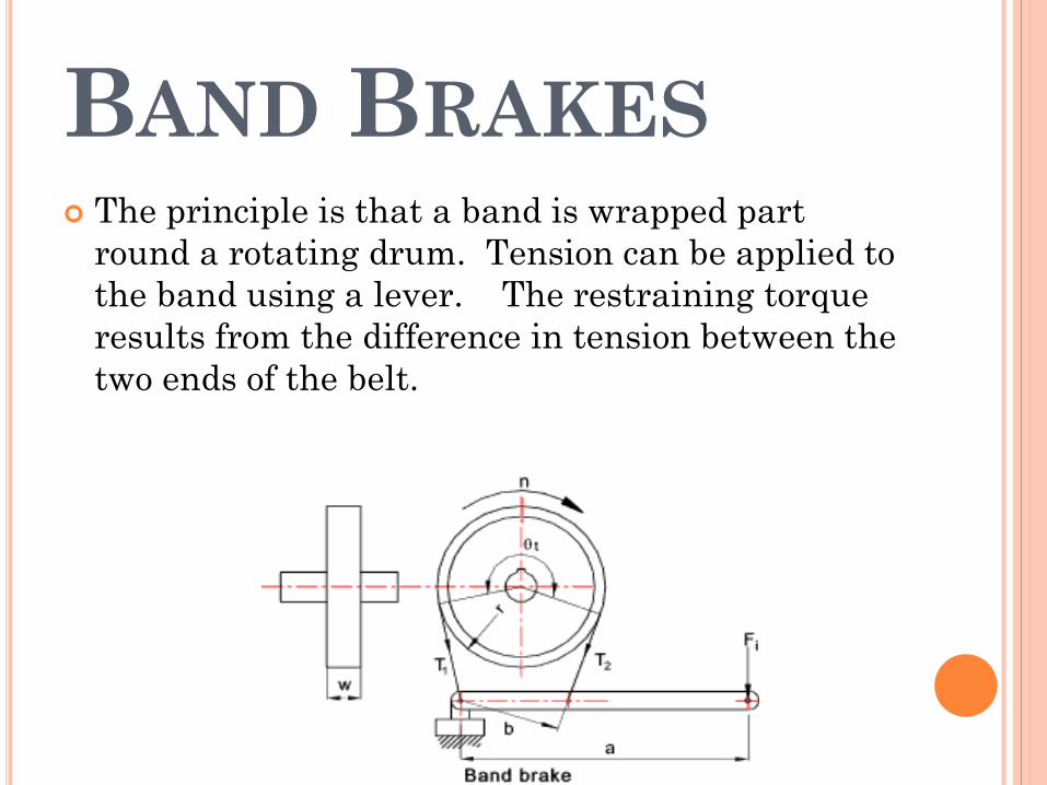
BAND BRAKES The principle is that a band is wrapped part
round a rotating drum. Tension can be applied to
the band using a lever. The restraining torque
results from the difference in tension between the
two ends of the belt.
HYDRAULLIC BRAKES
• The hydraulic brake is an arrangement
of braking mechanism which uses brake fluid specialy
ehtylene glycol to transfer pressure from the
controlling unit to the actual brake mechanism of the
vehicle.
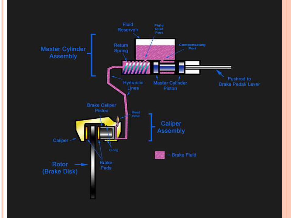
• Parts of hydaullic brakes:-
1. Brake Pedal
2. Push rod
3. Master cylinder assembly
4. Brake calliper assembly
CONT….
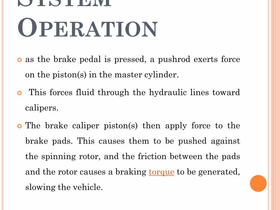
SYSTEM
OPERATION
as the brake pedal is pressed, a pushrod exerts force
on the piston(s) in the master cylinder.
This forces fluid through the hydraulic lines toward
calipers.
The brake caliper piston(s) then apply force to the
brake pads. This causes them to be pushed against
the spinning rotor, and the friction between the pads
and the rotor causes a braking torque to be generated,
slowing the vehicle.

ELECTRICAL
BRAKES• Electric brakes are actuator devices that use an electrical
current or magnetic actuating force to slow or stop the
motion of a rotating vehicle.
• There are two main types of electric brakes: magnetic
and friction.
• Magnetic brakes are non-contact brakes that use magnetic
fields to actuate the braking components.
• Permanent magnetic brake
• Electromagnetic brake
• Eddy current brakes
• Hysteresis powered brakes

PERMANENT
MAGNETIC BRAKE
1. Applications:- electric motors, Robotics
2. Advantages:- High and accurate Torque, long life,
unaffected by power supply, safe and easy to use
3. Disadvantages:- Require a constant current control
to offset the permanent magnetic field.
ELECTROMAGNETIC
BRAKE
1. Applications:- Copy machines, conveyor drives, packaging
machinery, printing machinery, food processing machinery
and factory automation.
2. Advantages:- Fast response time, smooth, reliable, and
backlash free operation, produce high torque, automatic air
gap available.
3. Disadvantages:- Braking force diminishes as speed
diminishes, load cannot be held at a standstill causing safety
concern.
EDDY CURRENT
BRAKES1. Applications:- Train and roller coaster brakes.
2. Advantages:- Noncontact, Frictionless,
resettable, light weight, few moving parts.
3. Disadvantages:- Unusable at low speeds,
generates heat.

HYSTERESIS POWERED
BRAKES1. Applications:- Food and drug packaging operations, clean
rooms, environmental test chambers, load simulation for
life testing on rotating devices, capping, bolting and other
screwing applications.
2. Advantages:- Long, maintenance-free life, cost effective,
operational, smoothness, torque repeatability, broad speed
range, environmental stability, high-dissipation capability.
The torque remains constant and smooth and responds
with increases and decreases in current.
3. Disadvantages:- Experience a salient-pole phenomenon
called "cogging", an undesirable, pulsating output torque
which prevents smooth and efficient operation of these
systems
SERVO BRAKE
SYSTEM1. Servo Mechanism:- A servomechanism, or servo, is an
automatic device that uses error-sensing negative
feedback to correct the performance of a mechanism. It
applies only to systems where the feedback or error-
correction signals help control mechanical position, speed or
other parameters. It is an electronically controlled
mechanical or hydraulic device permitting a large action or
strong forces to be controlled by a small electrical signal.
POWER BRAKES• These are the brakes in which power of engine or battery is
used to enhance the braking effort.
• These are of four types:- Vaccum Brakes, Air Brakes,
Hydraulic Booster Brake and Electro-Hydraulic Booster
brake.
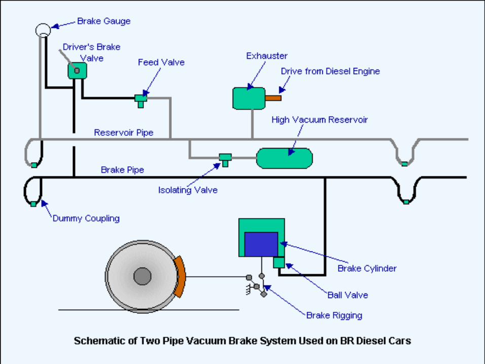
1. Vaccum Brakes:- Vacuum brake system is controlled
through a brake pipe connecting a brake valve in the
driver's cab with braking equipment on every vehicle. The
operation of the brake equipment on each vehicle depends
on the condition of a vacuum created in the pipe by an
ejector or exhauster.
2. Air Brakes:- The operatiom of air brakes is similar to
hydraullic brake except that compressed air is used to
apply brakes instead of hydraullic pressure. Air brakes are
commonly used on heavy vehicles like trucks, buses etc.
3. Antilock Brake System (ABS):- Due to excessive braking
brakes are locked which causes skidding. Skidding is
avoided by releasing braking pressure just before wheels
are lock up and then reapplying same. This process is calles
pressure modulation. A modern ABS consists of an
electronic control unit (ECU)., one sensor on each wheel,an
electrically driven hydraullic pump and pressure
accumlator. Accumlator is used to store hydraulic fluid to
maintain high pressure in braking system. It is charged
with nitrogrn gas. ECU monitors and controls the antilock
function when required.

THANK YOU

clutch
Clutch
➢A clutch is a mechanical device that engages and disengages the
power, transmission, especially from driving shaft to driven shaft.
➢When the clutch is in engaged position, the engine power or rotary motion
of engine crankshaft is transmitted to gear box and then to wheels.
➢When clutch is disengaged, the engine power does not reach to gear box
(and to wheels) although engine is running.
➢Clutch is also used to allow shifting or changing of gears when vehicle is
running. For shifting gears, clutch is first disengaged then gear is shifted and
then clutch is engaged. Clutch has to be disengaged to stop the vehicle and
also at the time of idling

PRINCIPLE OF CLUTCH
It operates on the principle of friction. When two surfaces are
brought in contact and are held against each other due to friction
between them, they can be used to transmit power. If one is rotated,
then other also rotates. One surface is connected to engine and
other to the transmission system of automobile. Thus, clutch is
nothing but a combination of two friction surfaces.
MAIN PARTS OF CLUTCH
It consists of
(a) a driving member,
(b) a driven member, and
(c) an operating member.
➢Driving member has a flywheel which is mounted on the engine
crankshaft. A disc is bolted to flywheel which is known as pressure
plate or driving disc.
➢The driven member is a disc called clutch plate. This plate can
slide freely to and fro on the clutch shaft.
➢The operating member consists of a pedal or lever which can be
pressed to disengaged the driving and driven plate.

TYPES OF CLUTCH
(a) Friction Clutch : It may be (i) single plate clutch, (ii) multi-plate
clutch, or (iii) cone clutch. Multi-plate clutch can be either wet or
dry. A wet clutch is operated in an oil batch whereas a dry clutch
does not use oil.
(b) Centrifugal clutch.
(c) Semi-centrifugal clutch.
(d) Hydraulic clutch.
(e) Positive clutch.
(f) Vacuum clutch.
(g) Electromagnetic clutch

Coupling
coupling
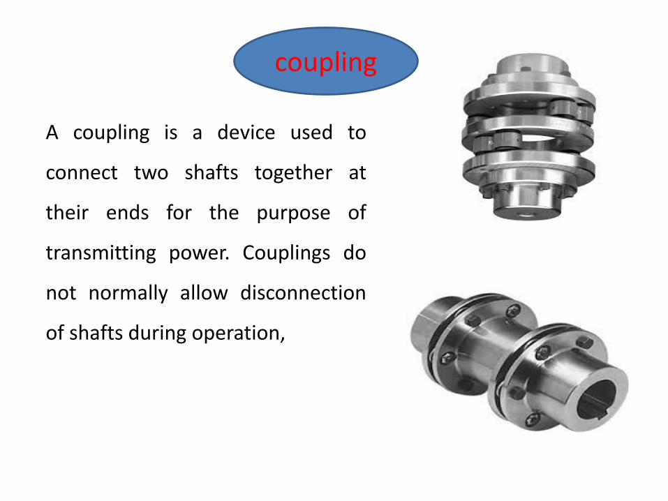
A coupling is a device used to
connect two shafts together at
their ends for the purpose of
transmitting power. Couplings do
not normally allow disconnection
of shafts during operation,

AdvanTges
✓It is easy to connect or disconnect.
✓It should transmit the full power from one shaft to the other
shaft without losses.
✓It hold shaft in perfect alignment.
✓It reduce the transmission of shock loads from one shaft
to another shaft.
Types of shaft
✓Rigid coupling
✓Flexible coupling

Rigid coupling
✓Sleeve and muff coupling .
✓Clamp or split muff coupling.
✓Flange coupling
Sleeve and muff coupling .
➢It consists of a hollow cylinder
whose Inner diameter is the same of
the shaft
✓It is fitted over the ends of the
two shafts by means of gib head key.
✓The power transmitted from one
shaft to other by means of key and
sleeve.

Clamp or split muff coupling.
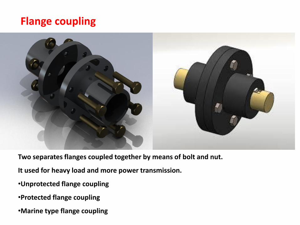
Flange coupling
Two separates flanges coupled together by means of bolt and nut.
It used for heavy load and more power transmission.
•Unprotected flange coupling
•Protected flange coupling
•Marine type flange coupling
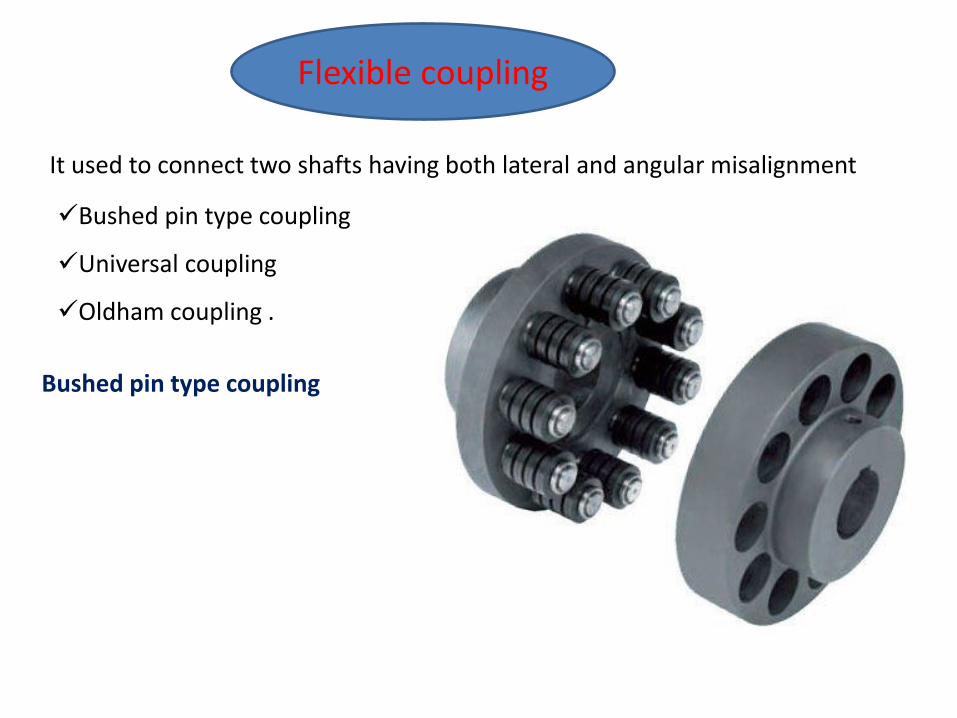
Flexible coupling
It used to connect two shafts having both lateral and angular misalignment
✓Bushed pin type coupling
✓Universal coupling
✓Oldham coupling .
Bushed pin type coupling

Universal coupling
Oldham coupling
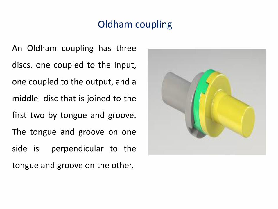
An Oldham coupling has three
discs, one coupled to the input,
one coupled to the output, and a
middle disc that is joined to the
first two by tongue and groove.
The tongue and groove on one
side is perpendicular to the
tongue and groove on the other.
✓The middle disc rotates around its centre at the same speed as
the input and output shafts.
✓Its centre traces a circular orbit, twice per rotation, around the
midpoint between input and output shafts. Often springs are used
to reduce backlash of the mechanism.
✓ An advantage to this type of coupling, as compared to two
universal joints, it is compact size.
Module -2
I C Engine Component
Introduction:
• An Engine is a device which transforms thechemical energy of a fuel into thermal energy anduses this thermal energy to produce mechanicalwork.
• Engines normally convert thermal energy intomechanical work and therefore they are calledheat engines.
• Heat engines can be broadly classified into :
• i) External combustion engines ( E C Engines)
• ii) Internal combustion engines ( I C Engines )


INTERNAL COMBUSTION ENGINE PARTS AND THEIR
FUNCTION
1. Cylinder :- It is a container fitted with piston, where the fuel is
burnt and power is produced.
2.Cylinder Head/Cylinder Cover:-One end of the cylinder is closed by
means of cylinder head. This consists of inlet valve for admitting air
fuel mixture and exhaust valve for removing the products of
combustion.
3. Piston:- Piston is used to reciprocate inside the cylinder. It
transmits the energy to crankshaft through connecting rod.
4. Piston Rings:- These are used to maintain a pressure tight seal
between the piston and cylinder walls and also it transfer the heat
from the piston head to cylinder walls.

5. Connecting Rod:- One end of the connecting rod is connected to
piston through piston pin while the other is connected to crank
through crank pin. It transmits the reciprocatory motion of piston to
rotary crank.
6. Crank:- It is a lever between connecting rod and crank shaft.
7. Crank Shaft:- The function of crank shaft is to transform
reciprocating motion in to a rotary motion.
8. Fly wheel:- Fly wheel is a rotating mass used as an energy storing
device.
9. Crank Case:- It supports and covers the cylinder and the crank
shaft. It is used to store the lubricating oil.

Bore: The inside diameter of the cylinder is called the bore.
Stroke: The linear distance along the cylinder axis between the two
limiting positions of the piston is called stroke.
Top Dead Centre (T.D.C) : The top most position of the piston
towards cover end side of the cylinder” is called top dead centre. In
case of horizontal engine, it is called as inner dead centre
Bottom Dead Centre (B.D.C):The lowest position of the piston
towards the crank end side of the cylinder is called bottom dead
centre. In case of horizontal engine, it is called outer dead centre
(O.D.C).
Clearance Volume: The volume contained in the cylinder above the top of
the piston, when the piston is at the top dead centre is called clearance
volume.
Compression ratio : It is the ratio of total cylinder volume to clearance
volume.
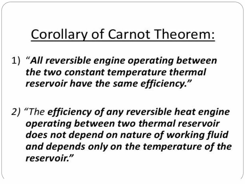
Laws of Thermodynamics


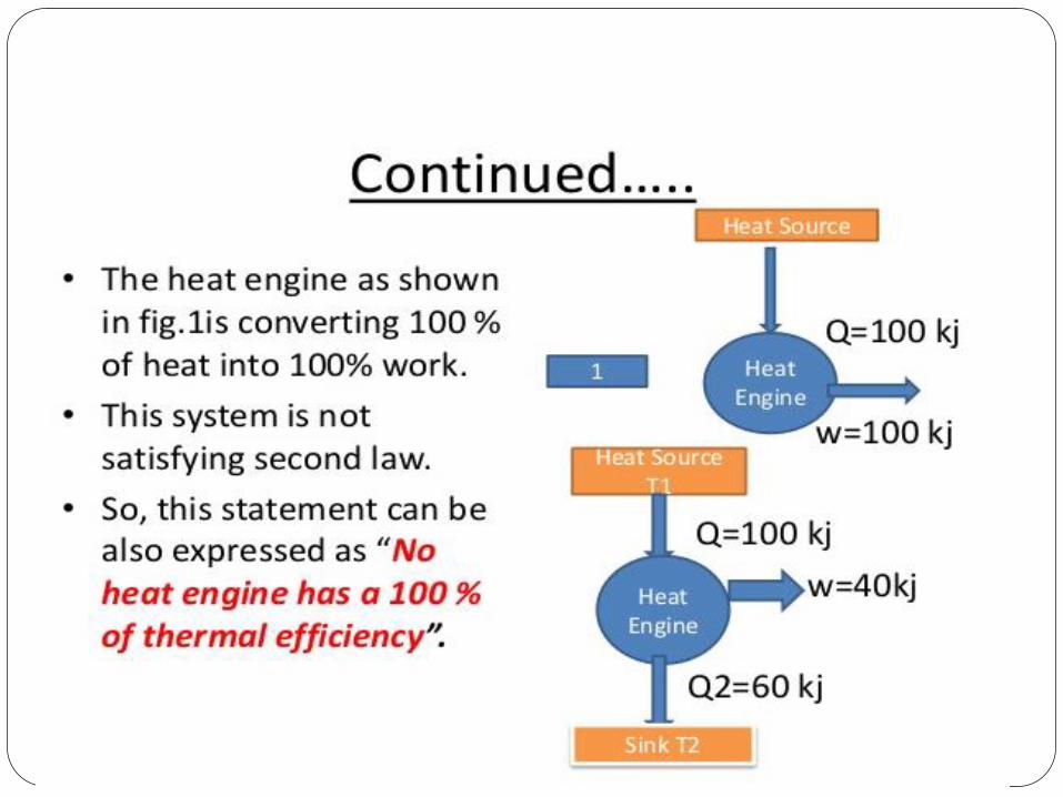


Violation of Kelvin-Plank Statement

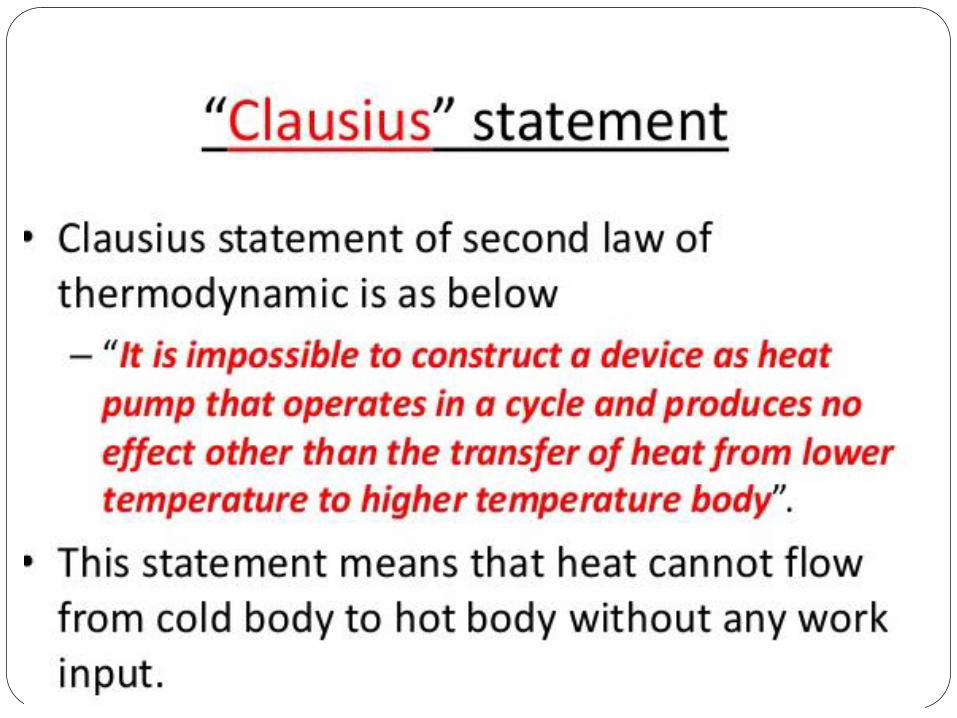
Violation of Clausius Statement


Pressure
Measurements
▪ INTRODUCTION
▪ UNITS OF PRESSURE
▪ CLASSIFICATION OF PRESSURE MEASUREMENT
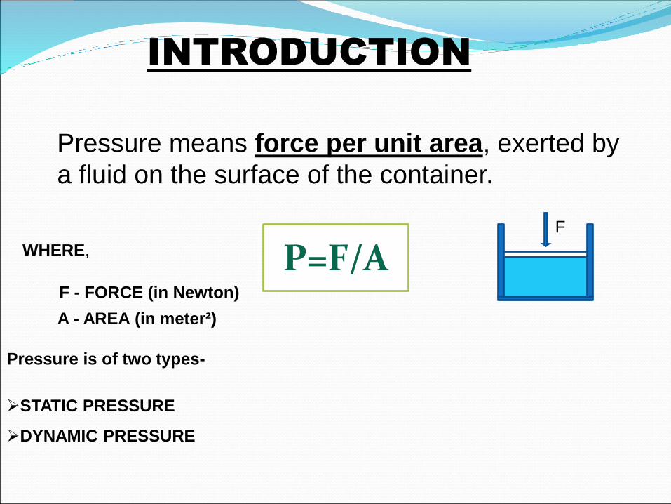
INTRODUCTION
Pressure means force per unit area, exerted by
a fluid on the surface of the container.
P=F/AF - FORCE (in Newton)
A - AREA (in meter²)
Pressure is of two types-
➢STATIC PRESSURE
➢DYNAMIC PRESSURE
WHERE,
F
➢Pressure is of two types-
1- STATIC PRESSURE
2- DYNAMIC PRESSURE
STATIC PRESSURE- when the force in a system under pressure is constant or static (i.e. unvarying), the pressure is said to be static pressure.
DYNAMIC PRESSURE- If the force is varying, on the other hand, the pressure is said to be dynamic pressure.

1 atm = 14.7 Psi at sea level
= 101.3 Kilo Pascal
= 760 mm of Hg
= 10.3 m of water
= 1013 mili bar
1 Pascal = 1N/m2
1 Bar = 100 Pascal
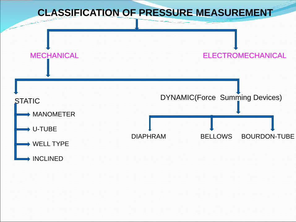
MECHANICAL ELECTROMECHANICAL
STATICDYNAMIC(Force Summing Devices)
MANOMETER
U-TUBE
WELL TYPE
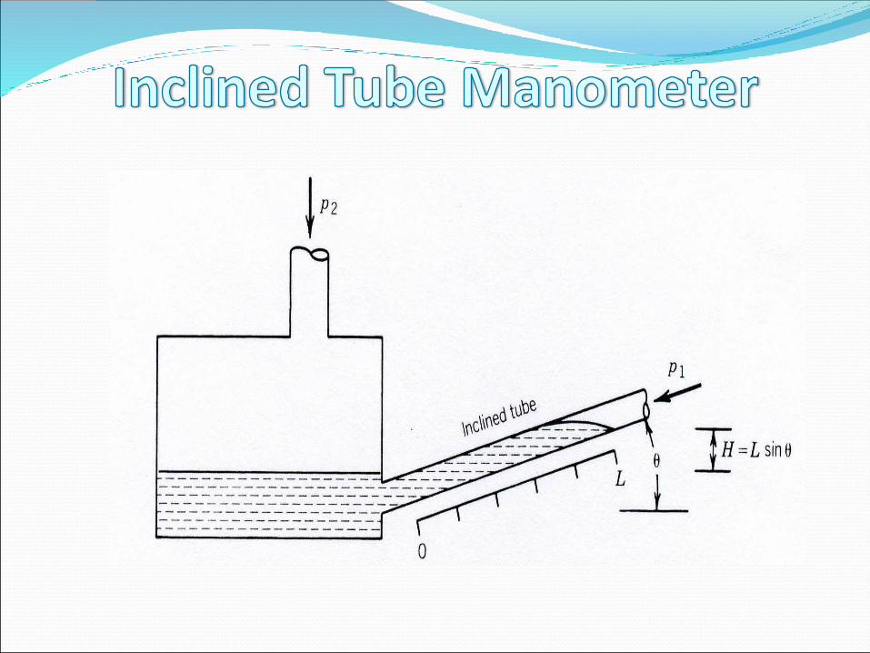
INCLINED
DIAPHRAM BELLOWS BOURDON-TUBE
CLASSIFICATION OF PRESSURE MEASUREMENT
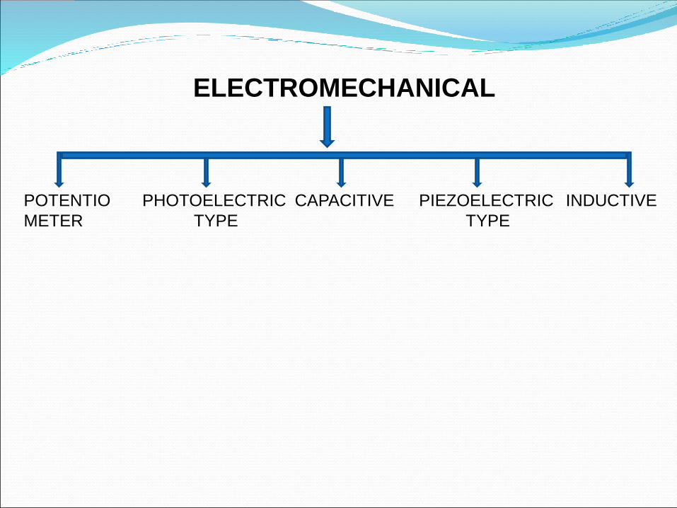
ELECTROMECHANICAL
POTENTIO
METER
PHOTOELECTRIC
TYPE
CAPACITIVE PIEZOELECTRIC
TYPE
INDUCTIVE
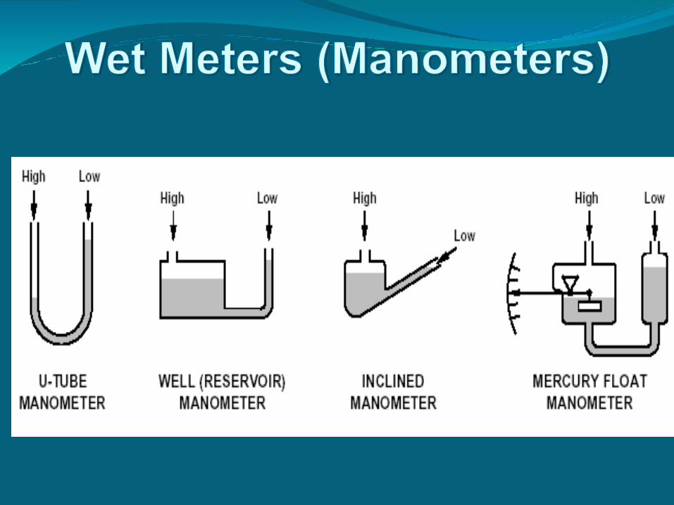
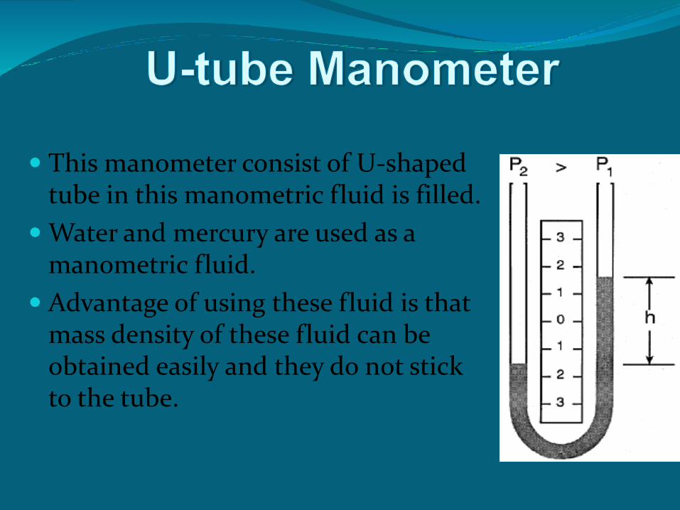
This manometer consist of U-shaped tube in this manometric fluid is filled.
Water and mercury are used as a manometric fluid.
Advantage of using these fluid is that mass density of these fluid can be obtained easily and they do not stick to the tube.
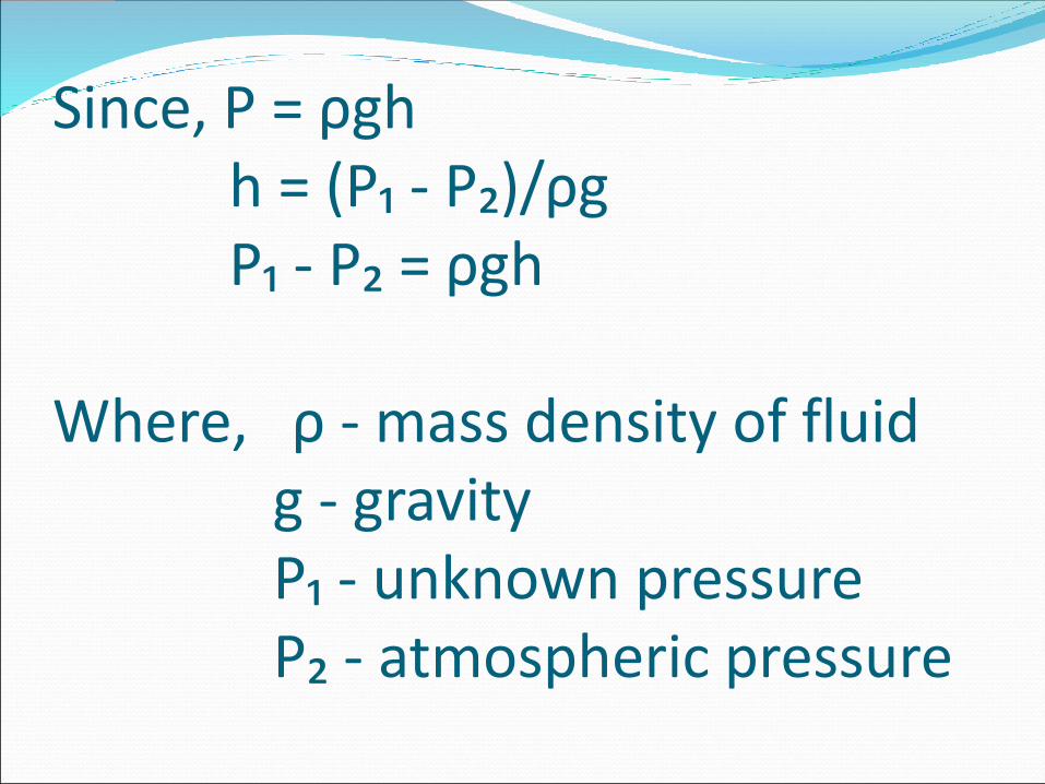
Since, P = ρghh = (P₁ - P₂)/ρgP₁ - P₂ = ρgh
Where, ρ - mass density of fluidg - gravityP₁ - unknown pressureP₂ - atmospheric pressure
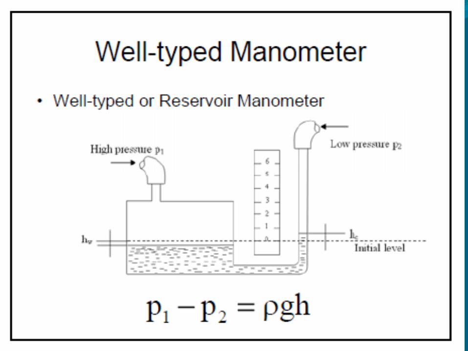
➢The well type manometer is widely usedbecause of inconvenience; the reading ofonly a single leg is required in it.It consist of a very large-diameter vessel(well) connected on one side to a verysmall-sized tube.Thus the zero level moves very little whenpressure is applied.
➢The force summing devices are those which converts the applied pressure into displacements by primary transducers while generated displacements may be measured by secondary transducers.
➢The commonly used force summing devices are-
1- DIAPHRAGM
2- BALLOWS
3- BOURDON TUBE
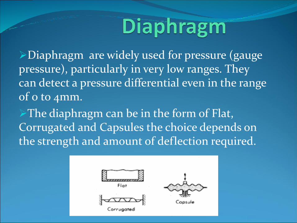
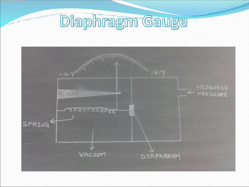
➢Diaphragm are widely used for pressure (gauge pressure), particularly in very low ranges. They can detect a pressure differential even in the range of 0 to 4mm.
➢The diaphragm can be in the form of Flat, Corrugated and Capsules the choice depends on the strength and amount of deflection required.
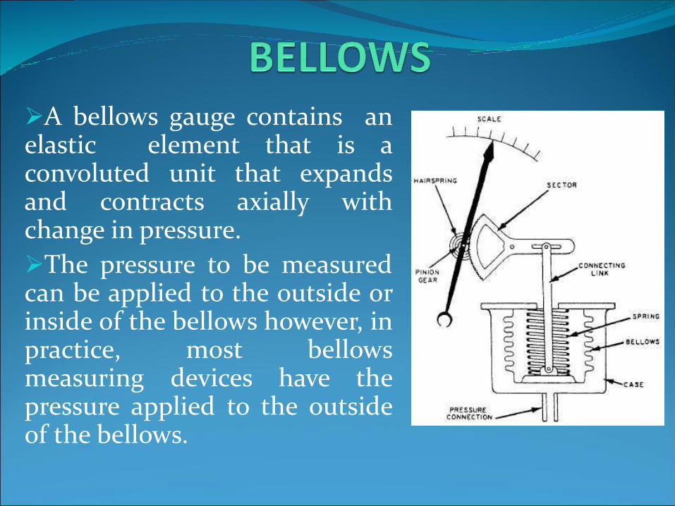
➢A bellows gauge contains anelastic element that is aconvoluted unit that expandsand contracts axially withchange in pressure.
➢The pressure to be measuredcan be applied to the outside orinside of the bellows however, inpractice, most bellowsmeasuring devices have thepressure applied to the outsideof the bellows.

➢An elastic transducer , that is bourdon tube which is fixed and open at one end to receive the pressure which is to be measured. The other end of the bourdon tube is free and closed.
➢The bourdon tube is in a bent form to look like a circular arc.
➢All the various form of bourdon tube have the common feature that they are constructed the tube of non circular cross-section


Chapter -2
REFRIGERATORS AND HEAT PUMPS

The transfer of heat from a low-
temperature region to a high-temperature
one requires special devices called
refrigerators
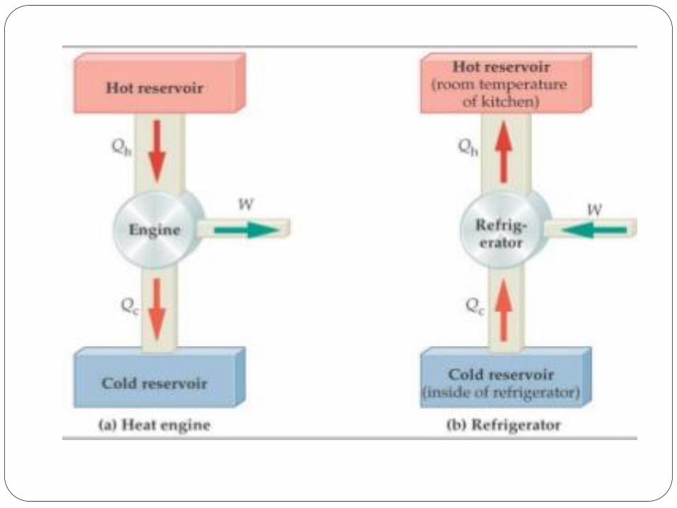
The objective of a refrigerator is to
remove heat (QL) from the cold medium;
the objective of a heat pump is to supply
heat (QH) to a warm medium.
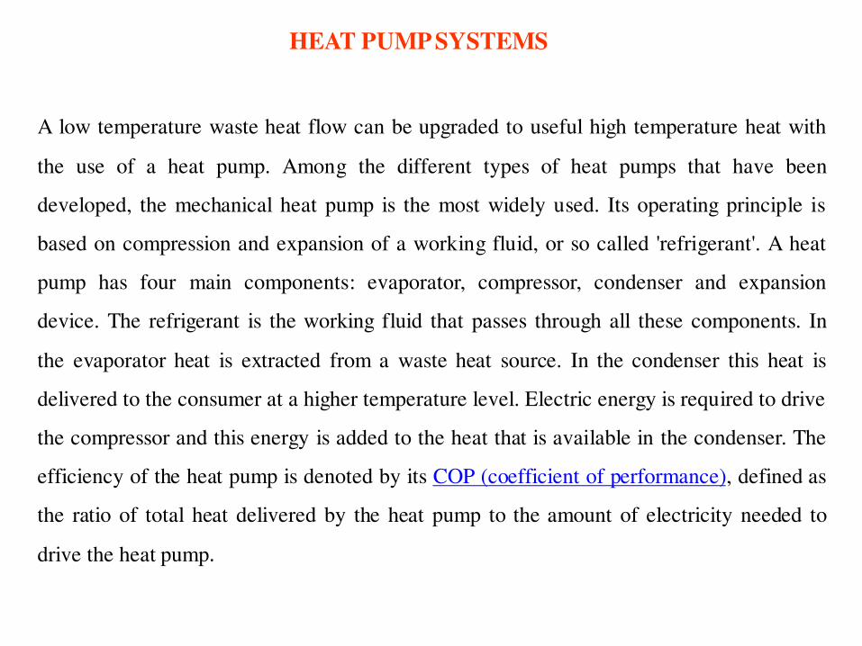
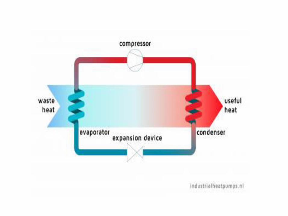
HEAT PUMP SYSTEMS
A low temperature waste heat flow can be upgraded to useful high temperature heat with
the use of a heat pump. Among the different types of heat pumps that have been
developed, the mechanical heat pump is the most widely used. Its operating principle is
based on compression and expansion of a working fluid, or so called 'refrigerant'. A heat
pump has four main components: evaporator, compressor, condenser and expansion
device. The refrigerant is the working fluid that passes through all these components. In
the evaporator heat is extracted from a waste heat source. In the condenser this heat is
delivered to the consumer at a higher temperature level. Electric energy is required to drive
the compressor and this energy is added to the heat that is available in the condenser. The
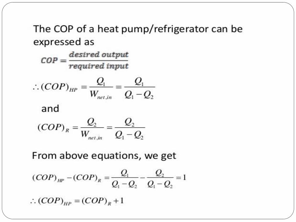
efficiency of the heat pump is denoted by its COP (coefficient of performance), defined as
the ratio of total heat delivered by the heat pump to the amount of electricity needed to
drive the heat pump.

Applications of Heat pumps
space heating; heating and cooling of process streams; water heating for washing, sanitation and cleaning; steam production; drying/dehumidification; evaporation; distillation; concentration

WORKING PRINCIPLE OF
REFRIGERATOR
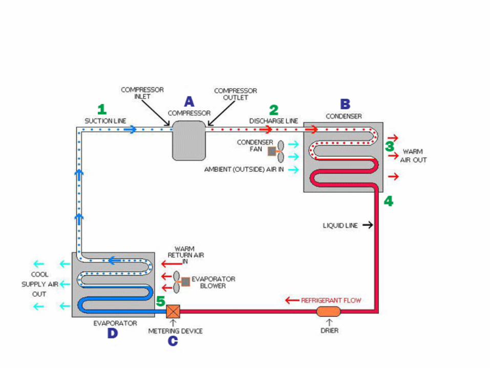

The letters A-D indicate the different system components. The numbers 1-5
indicate the different physical states of the refrigerant fluid as it moves
through the system.
State 1 is the state after the refrigerant passes through an evaporator (D), where
warm air heats the fluid and converts it completely to vapor.
State 2 is the state after the fluid passes through a compressor (A) which
increases the fluid's pressure and temperature up to superheated levels.
States 3 and 4 are when the fluid passes through an condensor (B),
which transfers heat to the ambient and condenses the fluid to liquid.
State 5 is the state after the fluid passes through an expansion valve or metering
device (C), which lowers the pressure of the fluid. This cools the fluid and
subsequently turns the liquid into a liquid/vapor mixture.

MODULE -2
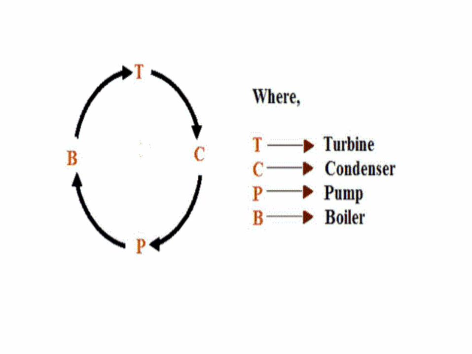
STEAM POWER PLANT

STEAM POWER PLANT
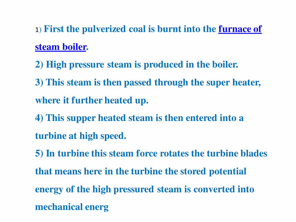
1) First the pulverized coal is burnt into the furnace of
steam boiler.
2) High pressure steam is produced in the boiler.
3) This steam is then passed through the super heater,
where it further heated up.
4) This supper heated steam is then entered into a
turbine at high speed.
5) In turbine this steam force rotates the turbine blades
that means here in the turbine the stored potential
energy of the high pressured steam is converted into
mechanical energ
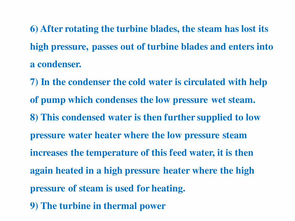
6) After rotating the turbine blades, the steam has lost its
high pressure, passes out of turbine blades and enters into
a condenser.
7) In the condenser the cold water is circulated with help
of pump which condenses the low pressure wet steam.
8) This condensed water is then further supplied to low
pressure water heater where the low pressure steam
increases the temperature of this feed water, it is then
again heated in a high pressure heater where the high
pressure of steam is used for heating.
9) The turbine in thermal power
Temperature Measurement

Introduction
The accurate measurement of temperature is vital across
abroad spectrum of human activities,
Including industrial processes (e.g. making steel)
Manufacturing;
Monitoring (in food transport and storage),
Health and safety.
In fact, in almost every sector, temperature is one of the
key parameters to be measured
The means of accurately measuring temperatures has long
fascinated people.
One of the differences between temperature and other
physical concepts, such as mass or length, is that it is
subjective.
Different people will have different perceptions of what is hot
and what is cold.
To make objective measurements, we must use thermometer
in which some physical property of a substance changes with
temperature in a reliable and reproducible way.
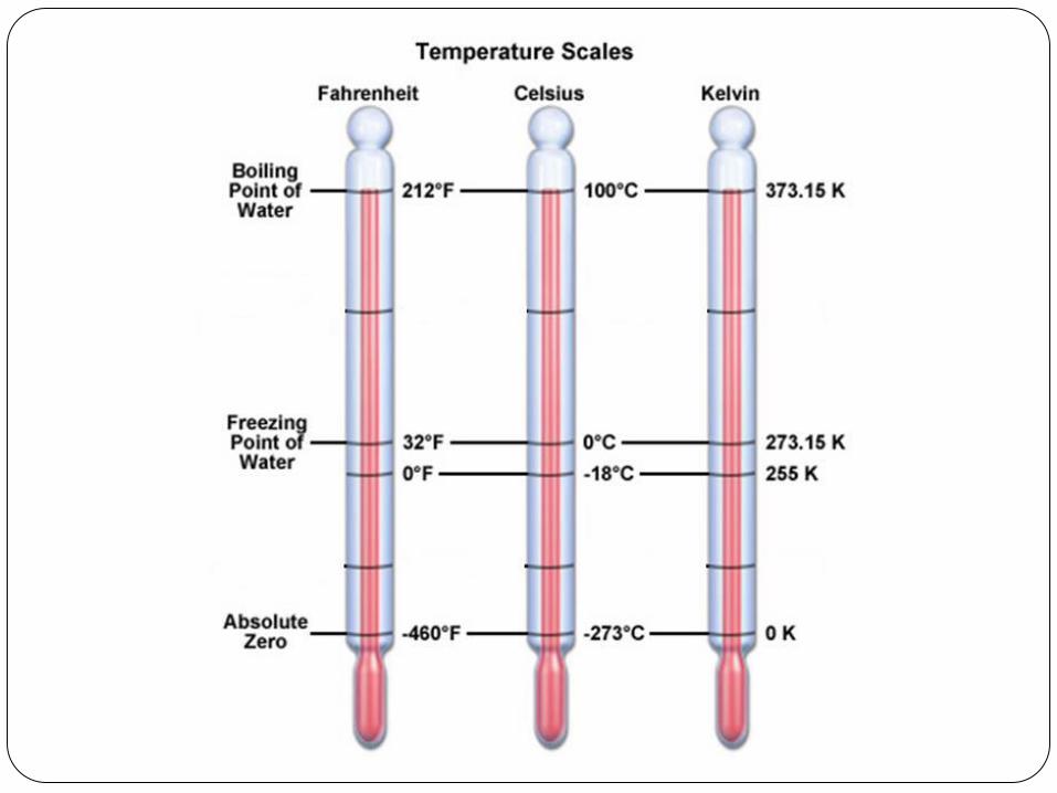
Scale Temperature is a measure of the thermal energy in the body.
Normally measured in degrees [°]using one of the
following scales.
1. Fahrenheit.[°F]
2. Celsius or centigrade. [°C]
3. Kelvin .[°K]
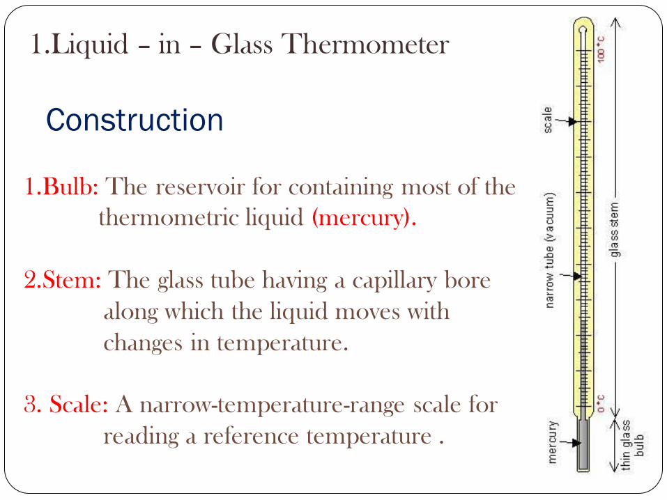
1.Bulb: The reservoir for containing most of the
thermometric liquid (mercury).
2.Stem: The glass tube having a capillary bore
along which the liquid moves with
changes in temperature.
3. Scale: A narrow-temperature-range scale for
reading a reference temperature .
Construction
1.Liquid – in – Glass Thermometer

The volume of mercury changes slightly with
temperature; the small change in volume drives the
narrow mercury column a relatively long way up the
tube.
The space above the mercury may be filled
with nitrogen or it may be at less than atmospheric
pressure, a partial vacuum.
Advantages
1) Simplicity in use & low cost.
2) Portable device.
3) Checking physical damage is easy.
4) Power source not require.
Disadvantages
1) Can not used for automatic recording.
2) Time lag in measurement.
3) Range is limited to about 300 °C .
2.Bimetallic Thermometer
In an industry, there is always a need to measure and
monitor temperature of a particular spot, field or
locality.
The industrial names given to such temperature
sensors are Temperature Indicators (TI) or
Temperature Gauges (TG).
All these temperature gauges belong to the class of
instruments that are known as bimetallic sensors.
Bimetallic Thermometer
Two basic principles of operation is to be followed in
the case of a bimetallic sensor.
1) A metal tends to undergo a volumetric dimensional
change (expansion/contraction), according to the
change in temperature.
2) Different metals have different co-efficient of temperatures. The rate of volumetric change
depends on this co-efficient of temperature.
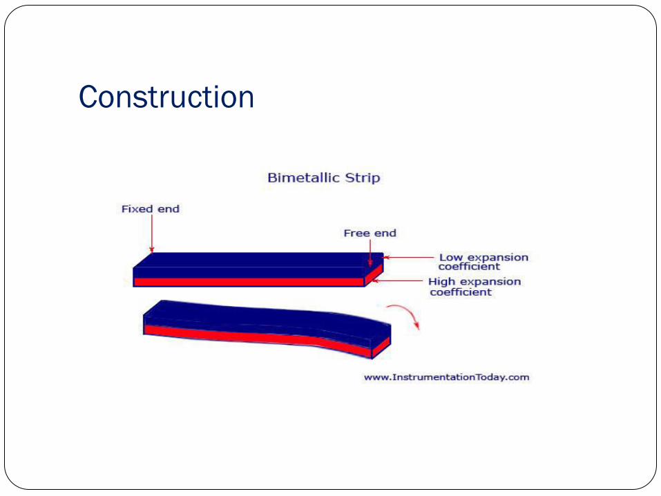

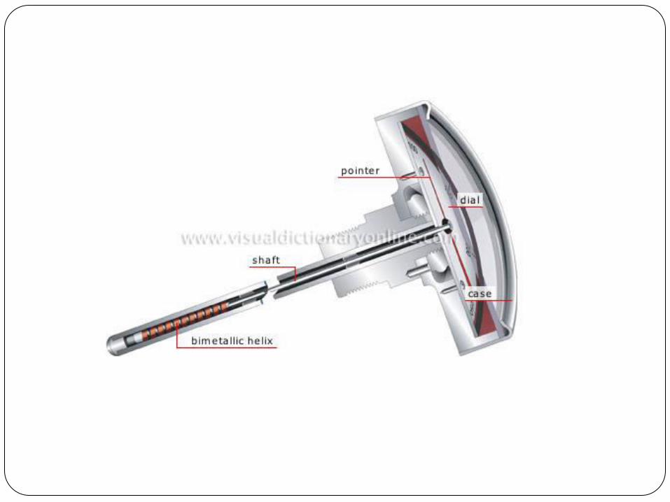
The device consists of a bimetallic strip of two different metals .
They are bonded together to form a spiral or a twisted helix.
Both these metals are joined together at one end by either welding or riveting.
It is bonded so strong that there will not be any relative motion between the two.
The image of a bimetallic strip is shown below.
Construction
A change in temperature causes the free end of the
strip to expand or contract due to the different
coefficients of expansion of the two metals.
This movement is linear to the change in
temperature and the deflection of the free end can be
read out by attaching a pointer to it.
This reading will indicate the value of temperature.
Bimetallic strips are available in different forms like
helix type, cantilever, spiral, and also flat type.
Advantages 1) Power source not required
2) Robust, easy to use and cheap.
3) Can be used to 500 °C.
Disadvantages 1) Not very accurate.
2) Limited to applications where manual reading is acceptable.
3) Not suitable for very low temperatures because the expansion of metals tend to be too similar, so the device becomes a rather insensitive thermometer
Pressure Thermometer
1. Liquid Pressure Thermometers.
2. Vapour Pressure Thermometers.
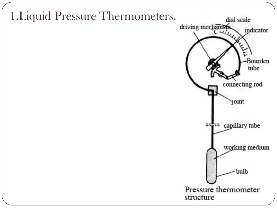
1.Liquid Pressure Thermometers.
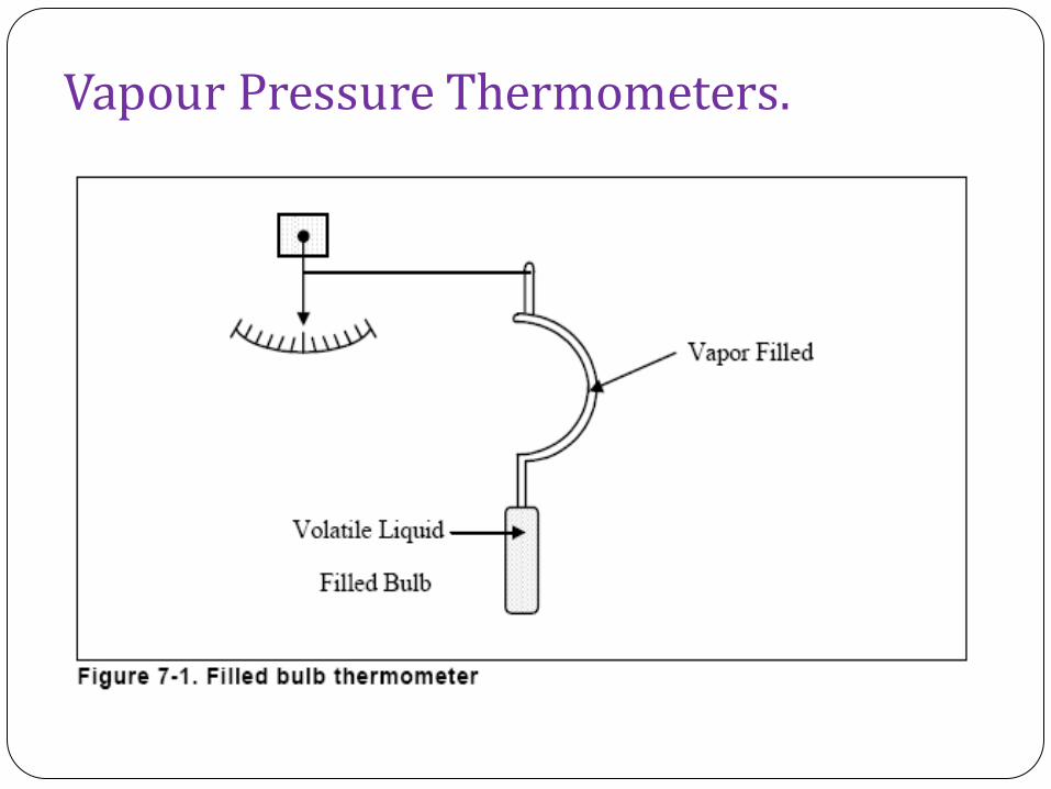
Vapour Pressure Thermometers.

Resistance Temperature Detector (RTD)
RTD can also be called a resistance thermometer as
the temperature measurement will be a measure of the
output resistance.
The main principle of operation of an RTD is that
when the temperature of an object increases or
decreases, the resistance also increases or decreases proportionally.
ie. positive temperature coefficient

RTD Types
RTD types are broadly classified according to the
different sensing elements used.
Platinum, Nickel and Copper are the most commonly
used sensing elements.
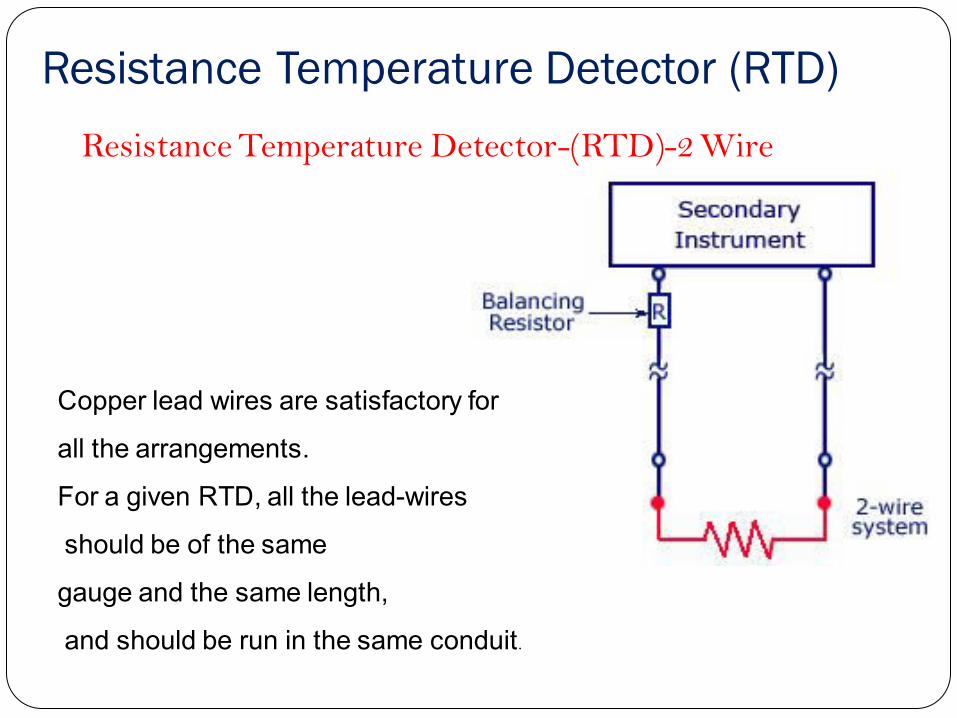
Resistance Temperature Detector (RTD)
Copper lead wires are satisfactory for
all the arrangements.
For a given RTD, all the lead-wires
should be of the same
gauge and the same length,
and should be run in the same conduit.
Resistance Temperature Detector-(RTD)-2 Wire
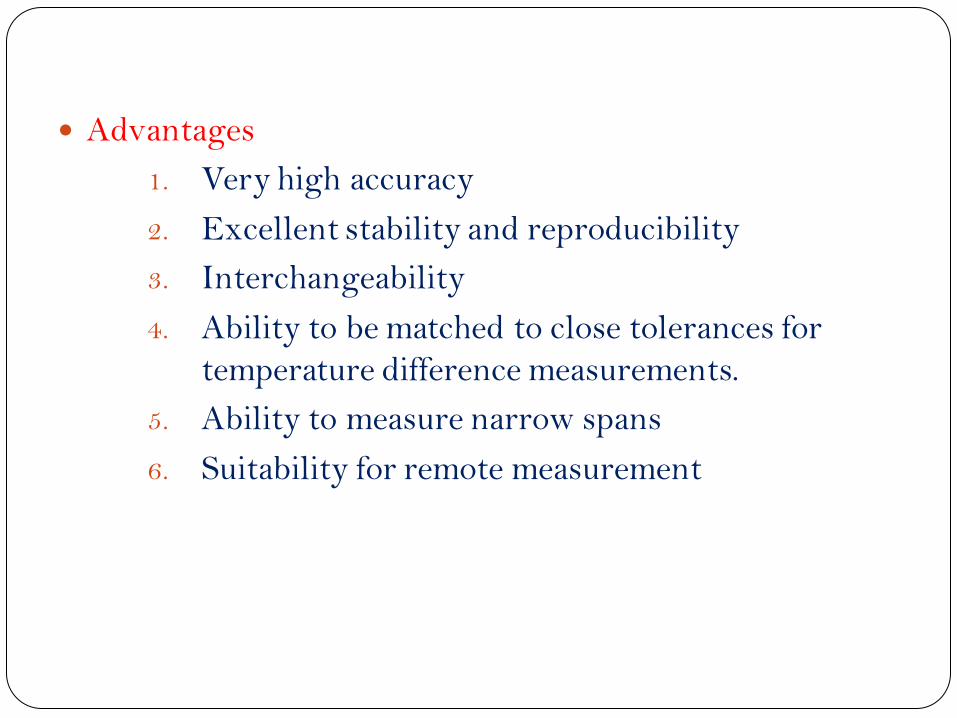
Advantages
1. Very high accuracy
2. Excellent stability and reproducibility
3. Interchangeability
4. Ability to be matched to close tolerances for temperature difference measurements.
5. Ability to measure narrow spans
6. Suitability for remote measurement
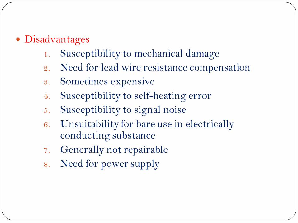
Disadvantages
1. Susceptibility to mechanical damage
2. Need for lead wire resistance compensation
3. Sometimes expensive
4. Susceptibility to self-heating error
5. Susceptibility to signal noise
6. Unsuitability for bare use in electrically conducting substance
7. Generally not repairable
8. Need for power supply
Pyrometer
A pyrometer is a device that is used for the temperature measurement of an object.
The device actually tracks and measures the amount of heat that is radiated from an object.
The thermal heat radiates from the object to the optical system present inside the pyrometer.
The optical system makes the thermal radiation into a better focus and passes it to the detector.

In an optical pyrometer, a brightness comparison is made to measure the temperature.
The device compares the brightness produced by the radiation of the object whose temperature is to be measured,
For an object, its light intensity always depends on the temperature of the object.
After adjusting the temperature, the current passing through it is measured using a multimeter, as its value will be proportional to the temperature of the source when calibrated.
The working of an optical pyrometer is shown in the figure below.


As shown in the figure above, an optical pyrometer has the following components.
1. An eye piece at the left side and an optical lens on the right.
2. A reference lamp, which is powered with the help of a battery.
3. A rheostat to change the current and hence the brightness intensity.
4. So as to increase the temperature range which is to be measured, an absorption screen is fitted between the optical lens and the reference bulb.
Working 1.The radiation from the source is emitted and the
optical objective lens captures it. 2.The lens helps in focusing the thermal radiation on to the
reference bulb. 3.The observer watches the process through the eye piece
and corrects it in such a manner that the reference lamp filament has a sharp focus and the filament is super-imposed on the temperature source image.
4.The observer starts changing the rheostat values and the current in the reference lamp changes.
5.This in turn, changes its intensity. This change in current can be observed in three different ways.

The filament is dark. That is, cooler than the temperature source.
Filament is bright. That is, hotter than the temperature source.
Filament disappears. Thus, there is equal brightness between the filament and temperature source
At this time, the current that flows in the reference lamp is measured, as its value is a measure of the temperature of the radiated light in the temperature source, when calibrated.
Advantages
1. Provides a very high accuracy with +/-5º Celsius.
2. The biggest advantage of this device is that, there is no direct contact between the pyrometer and the object whose temperature is to be found out.
Disadvantages
1. As the measurement is based on the light intensity, the device can be used only in applications with a minimum temperature of 700º Celsius.
2. The device is not useful for obtaining continuous values of temperatures at small intervals.
Applications
1. Used to measure temperatures of liquid metals or highly heated materials.
2. Can be used to measure furnace temperatures.

Radiation Pyrometer

the radiation pyrometer has an optical system, including a lens, a mirror and an adjustable eye piece. The heat energy emitted from the hot body is passed on to the optical lens, which collects it and is focused on to the detector with the help of the mirror and eye piece arrangement. The detector may either be a thermistor or photomultiplier tubes. Though the latter is known for faster detection of fast moving objects, the former may be used for small scale applications. Thus, the heat energy is converted to its corresponding electrical signal by the detector and is sent to the output temperature display device.


CONTENT
Thermodynamics
Application of Thermodynamics:
Introduction to Fluid Mechanics and Heat transfer:
Production processes
Engineering materials:
Fasteners and Power transmission devices:
Mechanical Measurements:
Chapter-1
Thermodynamics
What is Thermodynamics Themodynamics is derived from two Greek words :
therme & dynamics
Therme means heat and dynamics means transfer.
So Thermodynamics means the heat transfer between the systems.
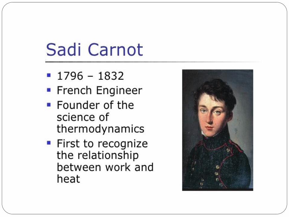
It is the relationship between
work
heat
other forms of energy.
Scope of Thermodynamics Knowledge of thermodynamics is required to design
any device involving the interchange between heat and work, or the conversion of material to produce heat (combustion).
Thermodynamics helps us to know about different processes occurring in our day-to-day life and how to deal with that.
System In Thermodynamics, the small region of the universe, on which
we are giving our concentration for our study is termed as SYSTEM.
System is of three types . They are open system closed system isolated system The rest of the universe outside the system close enough to the
system to have some perceptible effect on the system is called the SURROUNDINGS.
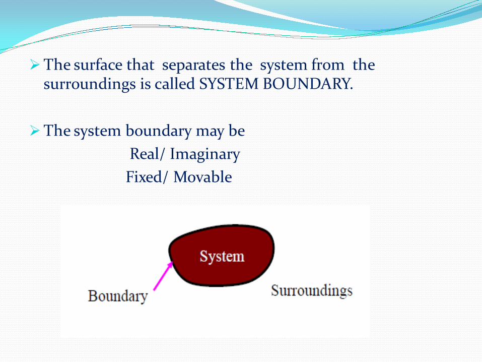
The surface that separates the system from the surroundings is called SYSTEM BOUNDARY.
The system boundary may be
Real/ Imaginary
Fixed/ Movable
Open System
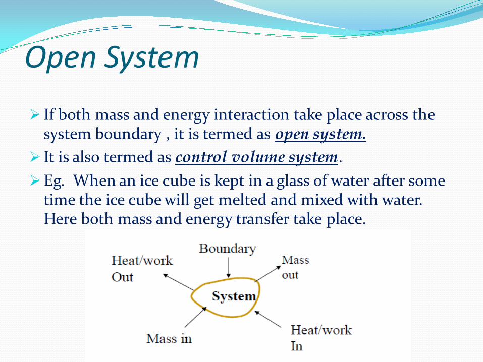
If both mass and energy interaction take place across the system boundary , it is termed as open system.
It is also termed as control volume system.
Eg. When an ice cube is kept in a glass of water after some time the ice cube will get melted and mixed with water. Here both mass and energy transfer take place.
Closed System
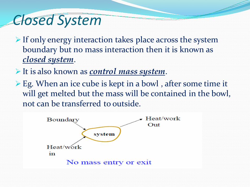
If only energy interaction takes place across the system boundary but no mass interaction then it is known as closed system.
It is also known as control mass system.
Eg. When an ice cube is kept in a bowl , after some time it will get melted but the mass will be contained in the bowl, not can be transferred to outside.

Isolated System If there is no mass nor energy interaction take place across
the system boundary, then it is termed as isolated system.

Types of systems Mass flow Work Heat
Open
Closed
× Isolated
× × × Thermally Isolated
× × Mechanically Isolated
× ×

Control Volume It is a properly selected region in space. It usually encloses a
device that involves mass flow such as a compressor, turbine, or nozzle.
In general, any arbitrary region in space can be selected as a control volume.
The boundaries of a control volume are called a control surface.
Macroscopic and Microscopic
approach of Thermodynamics MMacroscopic
acroscopic
MicrMicroscopic oscopic
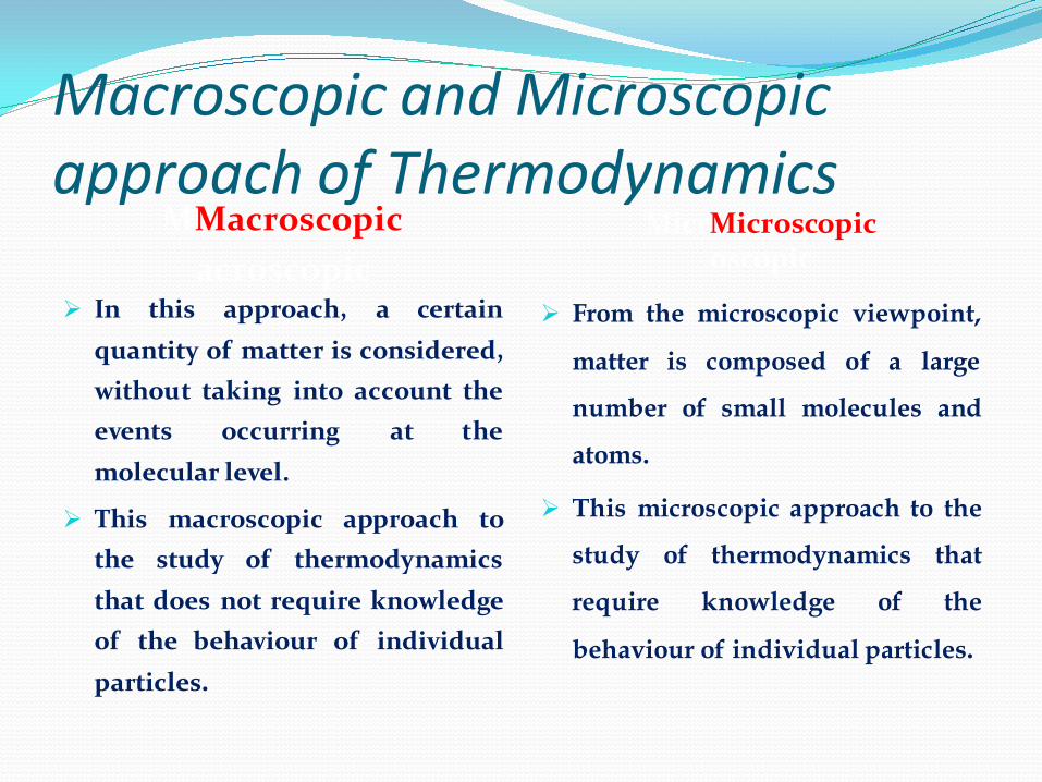
In this approach, a certain
quantity of matter is considered,
without taking into account the
events occurring at the
molecular level.
This macroscopic approach to
the study of thermodynamics
that does not require knowledge
of the behaviour of individual
particles.
From the microscopic viewpoint,
matter is composed of a large
number of small molecules and
atoms.
This microscopic approach to the
study of thermodynamics that
require knowledge of the
behaviour of individual particles.
Macroscopic Microscopic
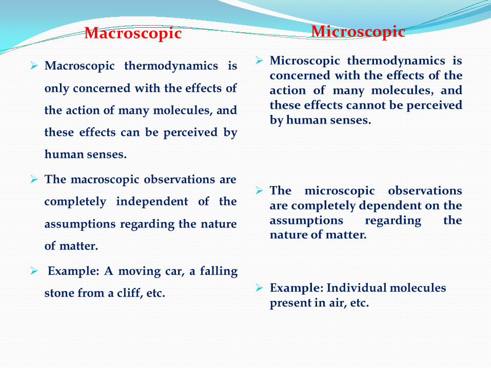
Macroscopic thermodynamics is
only concerned with the effects of
the action of many molecules, and
these effects can be perceived by
human senses.
The macroscopic observations are
completely independent of the
assumptions regarding the nature
of matter.
Example: A moving car, a falling
stone from a cliff, etc.
Microscopic thermodynamics is concerned with the effects of the action of many molecules, and these effects cannot be perceived by human senses.
The microscopic observations are completely dependent on the assumptions regarding the nature of matter.
Example: Individual molecules present in air, etc.
Properties of System Any characteristic of a system by which it’s physical condition may be described is called a property.
Pressure, temperature, volume, mass, viscosity, thermal
conductivity, modulus of elasticity, thermal expansion
coefficient, electric resistivity, velocity, elevation, etc.
Properties are considered to be either intensive or extensive.
Contd.. Intensive Property:- The property which is independent
of mass is termed as intensive property.
Eg. Temperature, pressure, specific volume, density etc. .
Extensive Property:- The property which is dependent on mass is termed as extensive property.
Eg. Mass, Volume, enthalpy, entropy etc. .
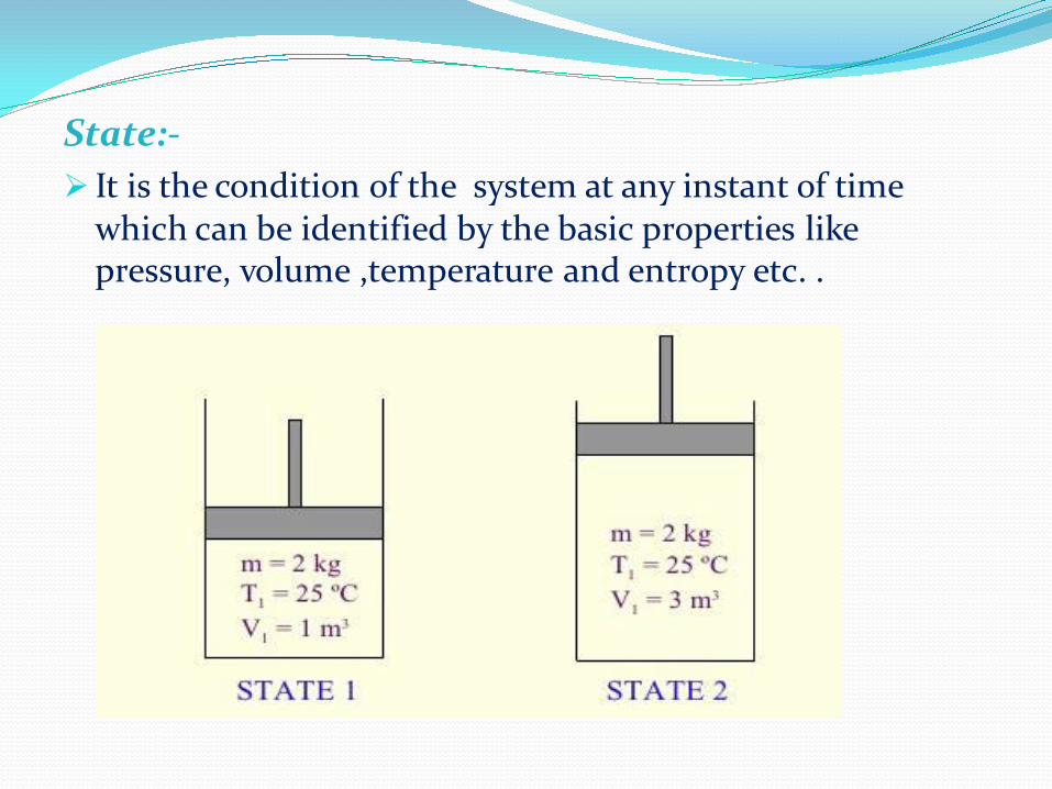
State:-
It is the condition of the system at any instant of time which can be identified by the basic properties like pressure, volume ,temperature and entropy etc. .

Path or Process:-
The succession of states passed through during a change of state is called the path of the system. A system is said to go through a process if it goes through a series of changes in state. Consequently:
It may be
reversible
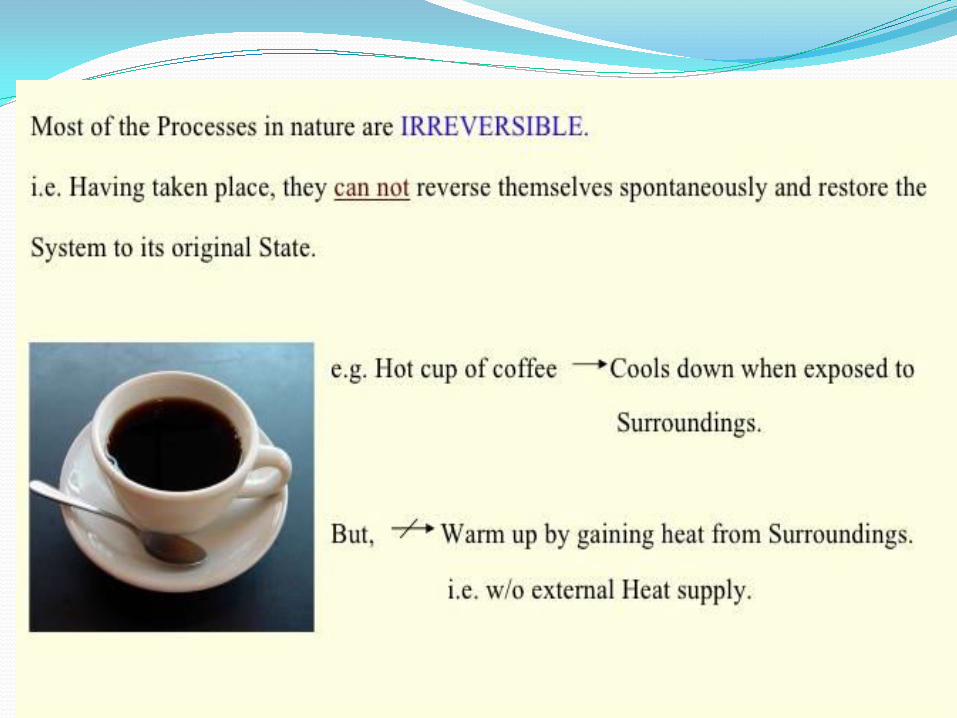
irreversible.
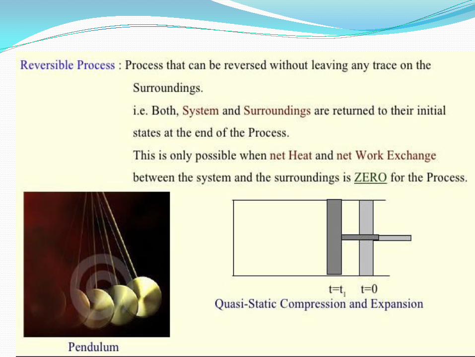
After removal of the force causing the motion if the system comes back to its initial state without leaving any stress on the surroundings, then it is known as reversible process.
After removal of the force causing the motion if the system comes back to its initial state leaving any stress on the surroundings, then it is known as irreversible process.
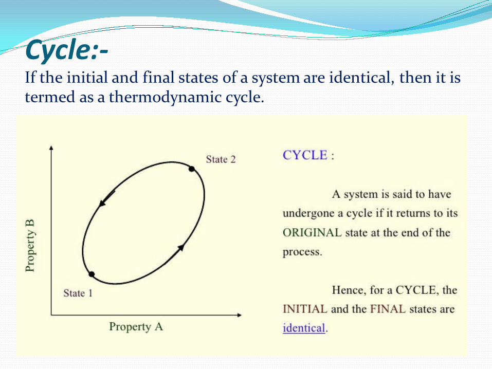
Cycle:- If the initial and final states of a system are identical, then it is termed as a thermodynamic cycle.

Types of processes Isothermal Process:- The process in which temperature
remains constant during the change of states is termed as Isothermal Process.
Isobaric Process:- The process in which pressure remains constant during the change of states is termed as Isobaric Process.
Isochoric Process:- The process in which volume remains constant during the change of states is termed as Isochoric Process.
Adiabatic Process:- The process in which there is no heat interaction between the system and the surroundings is called Adiabatic Process.
Contd.. Isentropic Process:- The process in which entropy remains
constant during the change of states is known as Isentropic Process.
Isenthalpic Process:- The process in which enthalpy remains constant during the change of states is known as Isenthalpic Process.
Polytropic Process:- A polytropic process is a thermodynamic process that obeys the relation:
PVⁿ = C
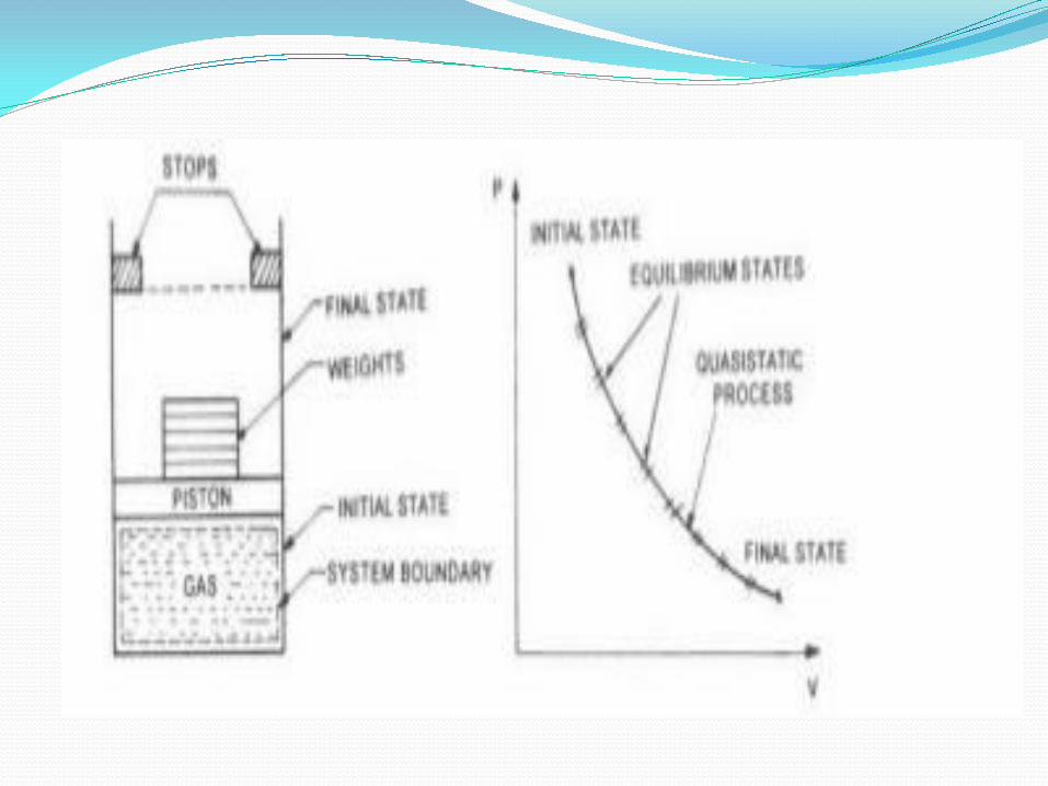
Quasistatic Process
Quasi-----almost
Static-----stable
A quasi-static process is a thermodynamic process that happens slowly enough for the system to remain in internal equilibrium.
When a process proceeds in such a manner that the system remains infinitesimally close to an equilibrium state all the time, it is called quasi-static or quasi-equilibrium process.
It is an idealised process and is not a true representation of the actual process.
Non-quasi-static process is not able to characterise the entire system by a single state, thus cannot tell the process path for the system as a whole.
Equilibrium State
A system is said to be in an equilibrium state if its
properties will not change without some perceivable
effect in the surroundings.
Equilibrium generally requires all properties to be uniform throughout the system.
There are mechanical, thermal, phase, and chemical equilibrium
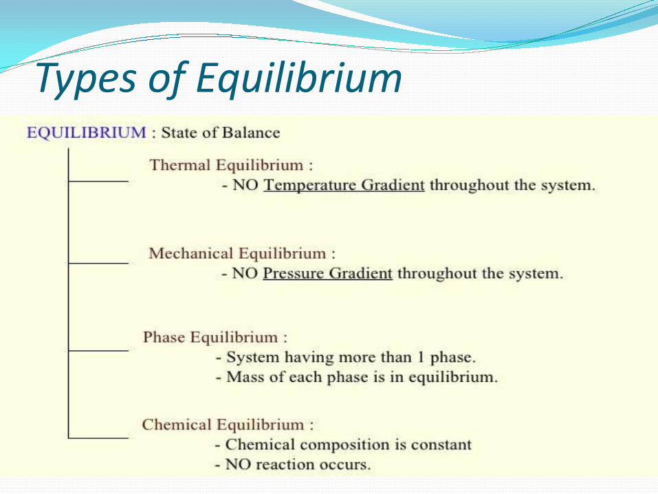
Types of Equilibrium

Point function & Path function Point function:-
If the thermodynamic property depends only on the state(point) but not on the path, then it is termed as Point function.
It is considered as the system property.
It has exact differential value at any instant of time.
Eg. Pressure,volume,temp,internal energy,enthapy,entropy etc.th function:-

If the thermodynamic property depends on both the nature of process between the states , then it is termed as Path function.
It is not considered as the system property.
It is inexact differential.
Eg. Work,heat etc


Velocity of fluid flow
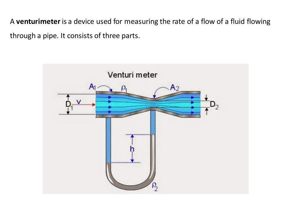
A venturimeter is a device used for measuring the rate of a flow of a fluid flowing
through a pipe. It consists of three parts.

1.A short converging part
2.Throat
3.Diverging part
It is based on the principle of Bernoulli’s equation. Inside of the venturimeter
pressure difference is created by reducing the cross-sectional area of the flow
passage. The pressure difference is measured by using a differential U-tube
manometer. This pressure difference helps in the determination of rate of flow
of fluid or discharge through the pipe line. As the inlet area of the venturi is large
than at the throat, the velocity at the throat increases resulting in decrease of
pressure. By this, a pressure difference is created between the inlet and the
throat of the venturi.
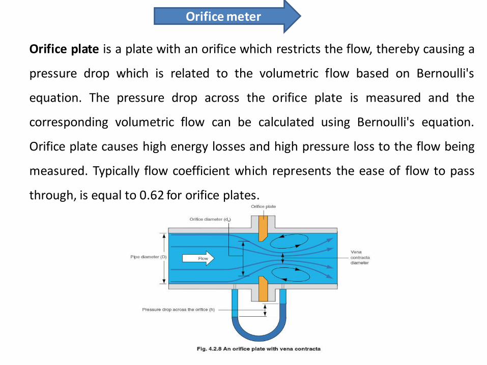
Orifice meter
Orifice plate is a plate with an orifice which restricts the flow, thereby causing a
pressure drop which is related to the volumetric flow based on Bernoulli's
equation. The pressure drop across the orifice plate is measured and the
corresponding volumetric flow can be calculated using Bernoulli's equation.
Orifice plate causes high energy losses and high pressure loss to the flow being
measured. Typically flow coefficient which represents the ease of flow to pass
through, is equal to 0.62 for orifice plates.
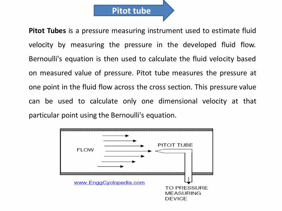
Pitot tube
Pitot Tubes is a pressure measuring instrument used to estimate fluid
velocity by measuring the pressure in the developed fluid flow.
Bernoulli's equation is then used to calculate the fluid velocity based
on measured value of pressure. Pitot tube measures the pressure at
one point in the fluid flow across the cross section. This pressure value
can be used to calculate only one dimensional velocity at that
particular point using the Bernoulli's equation.
3
4.2. Definitions Thermodynamics is the study of energy interactions between systems and the effect of these interactions on the system properties. Energy transfer between systems takes place in the form of heat and/or work. Thermodynamics deals with systems in equilibrium. A thermodynamic system is defined as a quantity of matter of fixed mass and identity upon which attention is focused for study. In simple terms, a system is whatever we want to study. A system could be as simple as a gas in a cylinder or as complex as a nuclear power plant. Everything external to the system is the surroundings. The system is separated from the surroundings by the system boundaries. Thermodynamic systems can be further classified into closed systems, open systems and isolated systems. A control volume, which may be considered as an open system, is defined as a specified region in space upon which attention is focused. The control volume is separated from the surroundings by a control surface. Both mass and energy can enter or leave the control volume.
The first and an extremely important step in the study of thermodynamics is to choose and identify the system properly and show the system boundaries clearly. A process is defined as the path of thermodynamic states which the system passes through as it goes from an initial state to a final state. In refrigeration and air conditioning one encounters a wide variety of processes. Understanding the nature of the process path is very important as heat and work depend on the path.
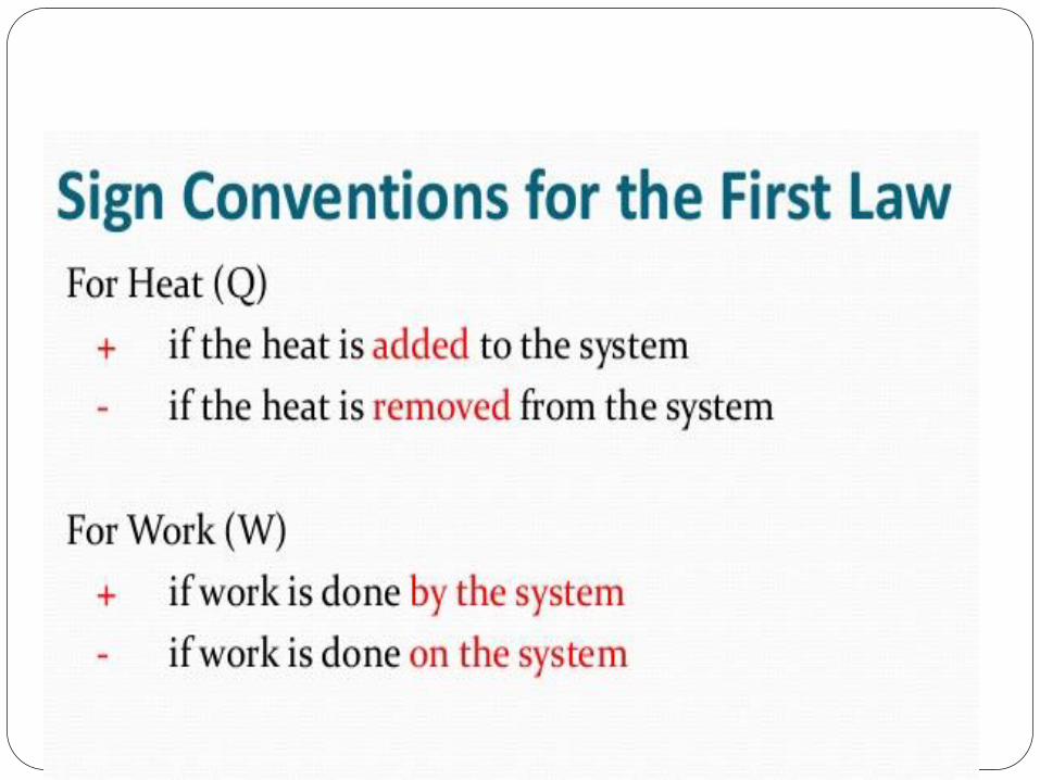
A system is said to have undergone a cycle if beginning with an initial state it goes through different processes and finally arrives at the initial state. 4.2.1. Heat and work:
Heat is energy transferred between a system and its surroundings by virtue of a temperature difference only. The different modes of heat transfer are: conduction, convection and radiation.
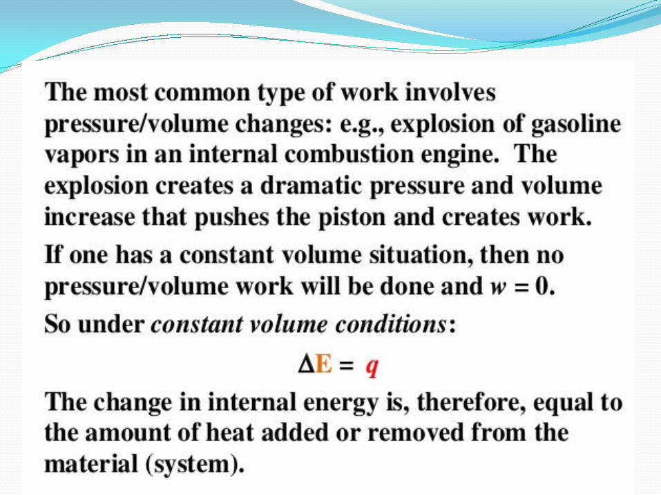
Heat is a way of changing the energy of a system by virtue of a temperature difference only. Any other means for changing the energy of a system is called work. We can have push-pull work (e.g. in a piston-cylinder, lifting a weight), electric and magnetic work (e.g. an electric motor), chemical work, surface tension work, elastic work, etc.
Mechanical modes of work: In mechanics work is said to be done when a force ‘F’ moves through a distance ‘dx’. When this force is a mechanical force, we call the work done as a mechanical mode of work. The classical examples of mechanical mode of work are:
1. Moving system boundary work 2. Rotating shaft work 3. Elastic work, and 4. Surface tension work
Version 1 ME, IIT Kharagpur 3

4
For a moving system boundary work, the work done during a process 1-2 is given by:
(4.1) ∫=2
121 dV.pW
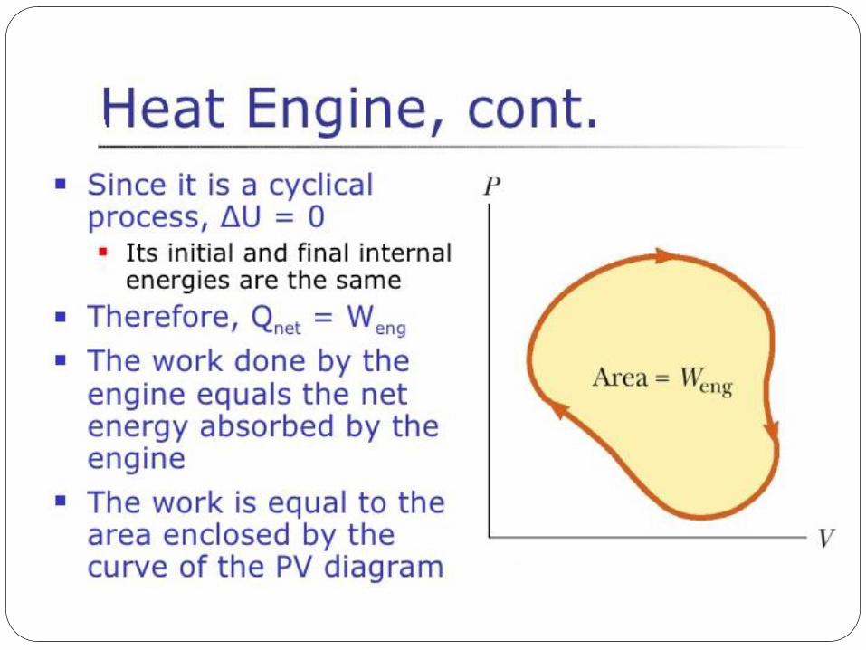
where ‘p’ is the pressure acting on the system boundary and ‘dV’ is the differential volume. It is assumed that the process is carried out very slowly so that at each instant of time the system is in equilibrium. Typically such a process is called a quasi-equilibrium process. For rigid containers, volume is constant, hence moving boundary work is zero in this case. For other systems, in order to find the work done one needs to know the relation between pressure p and volume V during the process. Sign convention for work and heat transfer: Most thermodynamics books consider the work done by the system to be positive and the work done on the system to be negative. The heat transfer to the system is considered to be positive and heat rejected by the system is considered to be negative. The same convention is followed throughout this course. 4.2.2. Thermodynamic Functions: There are two types of functions defined in thermodynamics, path function and point function. Path function depends on history of the system (or path by which system arrived at a given state). Examples for path functions are work and heat. Point function does not depend on the history (or path) of the system. It only depends on the state of the system. Examples of point functions are: temperature, pressure, density, mass, volume, enthalpy, entropy, internal energy etc. Path functions are not properties of the system, while point functions are properties of the system. Change in point function can be obtained by from the initial and final values of the function, whereas path has to defined in order to evaluate path functions. Figure 4.1 shows the difference between point and path functions. Processes A and B have same initial and final states, hence, the change in volume (DVA and DVB) for both these processes is same (3 m3), as volume is a point function, whereas the work transferred (WA and WB) for the processes is different since work is a path function. It should also be noted that the cyclic integrals of all point functions is zero, while the cyclic integrals of path functions may be or may not be zero.
Version 1 ME, IIT Kharagpur 4 Fig. 4.1. Difference between point and path functions

5
4.3. Thermodynamic properties
A system is specified and analyzed in terms of its properties. A property is any characteristic or attribute of matter, which can be evaluated quantitatively. The amount of energy transferred in a given process, work done, energy stored etc. are all evaluated in terms of the changes of the system properties. A thermodynamic property depends only on the state of the system and is independent of the path by which the system arrived at the given state. Hence all thermodynamic properties are point functions. Thermodynamic properties can be either intensive (independent of size/mass, e.g. temperature, pressure, density) or extensive (dependent on size/mass, e.g. mass, volume) Thermodynamic properties relevant to refrigeration and air conditioning systems are temperature, pressure, volume, density, specific heat, enthalpy, entropy etc.
It is to be noted that heat and work are not properties of a system. Some of the properties, with which we are already familiar, are: temperature, pressure, density, specific volume, specific heat etc. Thermodynamics introduces certain new properties such as internal energy, enthalpy, entropy etc. These properties will be described in due course. 4.3.1. State postulate: This postulate states that the number of independent intensive thermodynamic properties required to specify the state of a closed system that is:
a) Subject to conditions of local equilibrium b) Exposed to ‘n’ different (non-chemical) work modes of energy transport, and c) Composed of ‘m’ different pure substances
is (n+m). For a pure substance (m = 1) subjected to only one work mode (n = 1) two independent intensive properties are required to fix the state of the system completely (n + m = 2). Such a system is called a simple system. A pure gas or vapour under compression or expansion is an example of a simple system. Here the work mode is moving system boundary work. 4.4. Fundamental laws of Thermodynamics Classical thermodynamics is based upon four empirical principles called zeroth, first, second and third laws of thermodynamics. These laws define thermodynamic properties, which are of great importance in understanding of thermodynamic principles. Zeroth law defines temperature; first law defines internal energy; second law defines entropy and the third law can be used to obtain absolute entropy values. The above four thermodynamic laws are based on human observation of natural phenomena; they are not mathematically derived equations. Since no exceptions to these have been observed; these are accepted as laws. Conservation of mass is a fundamental concept, which states that mass is neither created nor destroyed.
The Zeroth law of thermodynamics states that when two systems are in thermal equilibrium with a third system, then they in turn are in thermal equilibrium with each other. This implies that
Version 1 ME, IIT Kharagpur 5
6
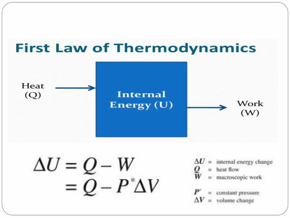
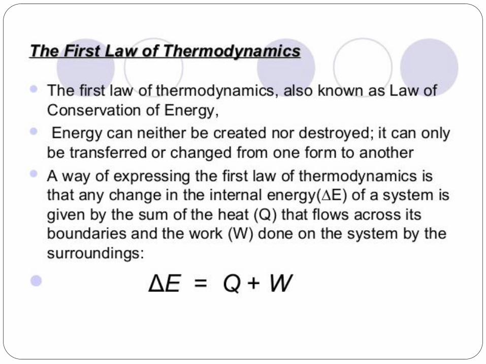
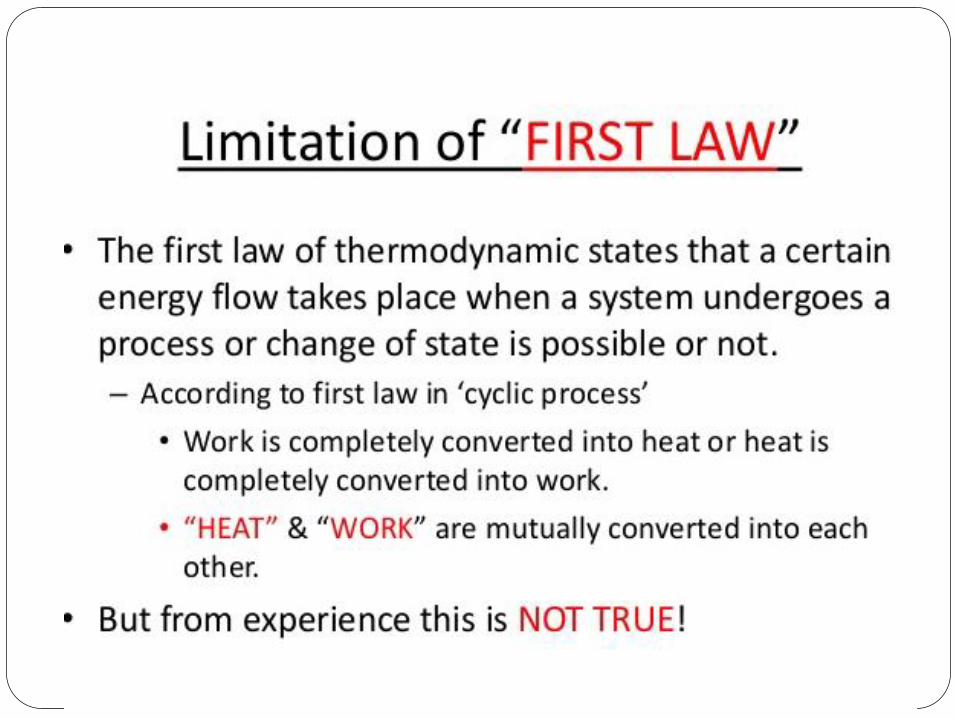
some property must be same for the three systems. This property is temperature. Thus this law is the basis for temperature measurement. Equality of temperature is a necessary and sufficient condition for thermal equilibrium, i.e. no transfer of heat. The First law of thermodynamics is a statement of law of conservation of energy. Also, according to this law, heat and work are interchangeable. Any system that violates the first law (i.e., creates or destroys energy) is known as a Perpetual Motion Machine (PMM) of first kind. For a system undergoing a cyclic process, the first law of thermodynamics is given by:
∫ ∫= WQ δδ (4.2)
where ∫ = cycletheduringtransferheatnetQδ ∫ = cycletheduringtransferworknetWδ Equation (4.2) can be written as:
∫ =− 0)WQ( δδ (4.3) This implies that )WQ( δδ − must be a point function or property of the system. This property is termed as internal energy, U. Mathematically, internal energy can be written as:
WQdU δδ −= (4.4)
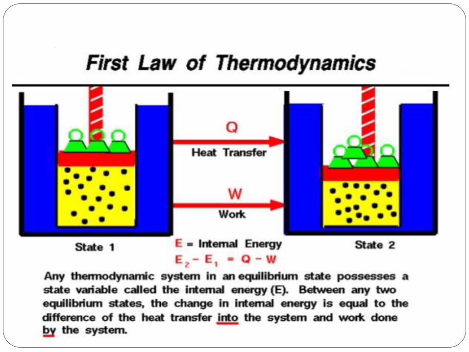
The internal energy of a system represents a sum total of all forms of energy viz. thermal, molecular, lattice, nuclear, rotational, vibrational etc. 4.4.1. First law of thermodynamics for a closed system: Let the internal energy of a closed system at an equilibrium state 1 be U1. If 1Q2 amount of heat is transferred across its boundary and 1W2 is the amount of work done by the system and the system is allowed to come to an equilibrium state 2. Then integration of Eqn. (4.4) yields,
2 1 1 2 1U U Q W2− = − (4.5)
If m is the mass of the system and u denotes the specific internal energy of the system then,
2 1 1 2 1 2( ) (m u u m q w )− = − (4.6) or, 2 1 1 2 1u u q w2− = − (4.7)
where, 1q2 and 1w2 are heat transfer and work done per unit mass of the system. Flow Work: In an open system some matter, usually fluid enters and leaves the system. It requires flow work for the fluid to enter the system against the system pressure and at the same time flow work is required to expel the fluid from the system. It can be shown that the specific flow work is given by the product of pressure, p and specific volume, v, i.e., flow work = pv.
Version 1 ME, IIT Kharagpur 6
7
Enthalpy: In the analysis of open systems, it is convenient to combine the specific flow work ‘pv’ with internal energy ‘u’ as both of them increase the energy of the system. The sum of specific internal energy and specific flow work is an intensive property of the system and is called specific enthalpy, h. Thus specific enthalpy, h is given by:
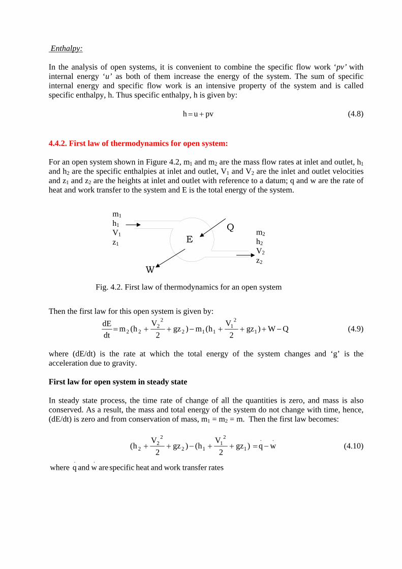
pvuh += (4.8) 4.4.2. First law of thermodynamics for open system: For an open system shown in Figure 4.2, m1 and m2 are the mass flow rates at inlet and outlet, h1 and h2 are the specific enthalpies at inlet and outlet, V1 and V2 are the inlet and outlet velocities and z1 and z2 are the heights at inlet and outlet with reference to a datum; q and w are the rate of heat and work transfer to the system and E is the total energy of the system.
Q
W
m2h2 V2z2
m1h1 V1z1 E
Fig. 4.2. First law of thermodynamics for an open system
Then the first law for this open system is given by:
QW)gz2
Vh(m)gz
2V
h(mdtdE
1
21
112
22
22 −+++−++= (4.9)
where (dE/dt) is the rate at which the total energy of the system changes and ‘g’ is the acceleration due to gravity. First law for open system in steady state In steady state process, the time rate of change of all the quantities is zero, and mass is also conserved. As a result, the mass and total energy of the system do not change with time, hence, (dE/dt) is zero and from conservation of mass, m1 = m2 = m. Then the first law becomes:
..
1
21
12
22
2 wq)gz2
Vh()gz
2V
h( −=++−++ (4.10)
ratestransferworkandheatspecificarewandqwhere..
Version 1 ME, IIT Kharagpur 7
8
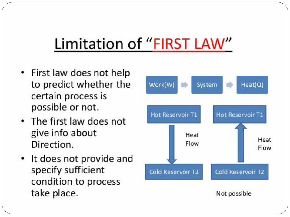
Second law of thermodynamics: The second law of thermodynamics is a limit law. It gives the upper limit of efficiency of a system. The second law also acknowledges that processes follow in a certain direction but not in the opposite direction. It also defines the important property called entropy.
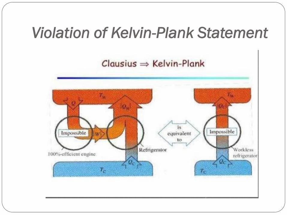
It is common sense that heat will not flow spontaneously from a body at lower temperature to a body at higher temperature. In order to transfer heat from lower temperature to higher temperature continuously (that is, to maintain the low temperature) a refrigeration system is needed which requires work input from external source. This is one of the principles of second law of thermodynamics, which is known as Clausius statement of the second law. Clausius’ statement of second law
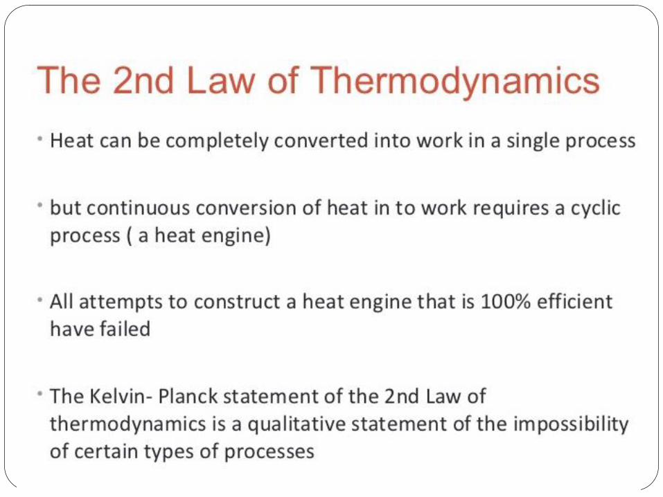
It is impossible to transfer heat in a cyclic process from low temperature to high temperature without work from external source. It is also a fact that all the energy supplied to a system as work can be dissipated as heat transfer. On the other hand, all the energy supplied as heat transfer cannot be continuously converted into work giving a thermal efficiency of 100 percent. Only a part of heat transfer at high temperature in a cyclic process can be converted into work, the remaining part has to be rejected to surroundings at lower temperature. If it were possible to obtain work continuously by heat transfer with a single heat source, then automobile will run by deriving energy from atmosphere at no cost. A hypothetical machine that can achieve it is called Perpetual Motion Machine of second kind. This fact is embedded in Kelvin-Planck Statement of the Second law.
Kelvin-Planck statement of second law It is impossible to construct a device (engine) operating in a cycle that will produce no effect other than extraction of heat from a single reservoir and convert all of it into work. Mathematically, Kelvin-Planck statement can be written as:
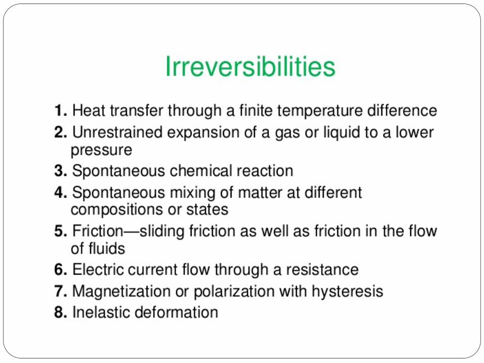
0Wcycle ≤ (for a single reservoir) (4.11) Reversible and Irreversible Processes A process is reversible with respect to the system and surroundings if the system and the surroundings can be restored to their respective initial states by reversing the direction of the process, that is, by reversing the heat transfer and work transfer. The process is irreversible if it cannot fulfill this criterion. If work is done in presence of friction, say by movement of piston in a cylinder then a part of the work is dissipated as heat and it cannot be fully recovered if the direction of process is reversed. Similarly, if heat is transferred through a temperature difference from higher temperature to a lower temperature, its direction cannot be reversed since heat transfer from lower temperature to higher temperature would require external work input. These are two examples of irreversible processes.
Version 1 ME, IIT Kharagpur 8

9
Reversible process is a hypothetical process in which work is done in absence of friction and heat transfer occurs isothermally. Irreversibility leads to loss in work output and loss in availability and useful work.
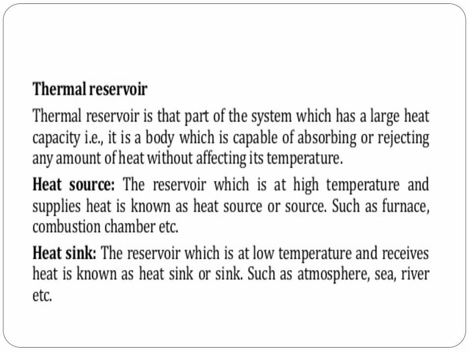
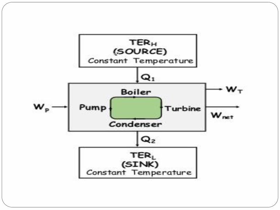
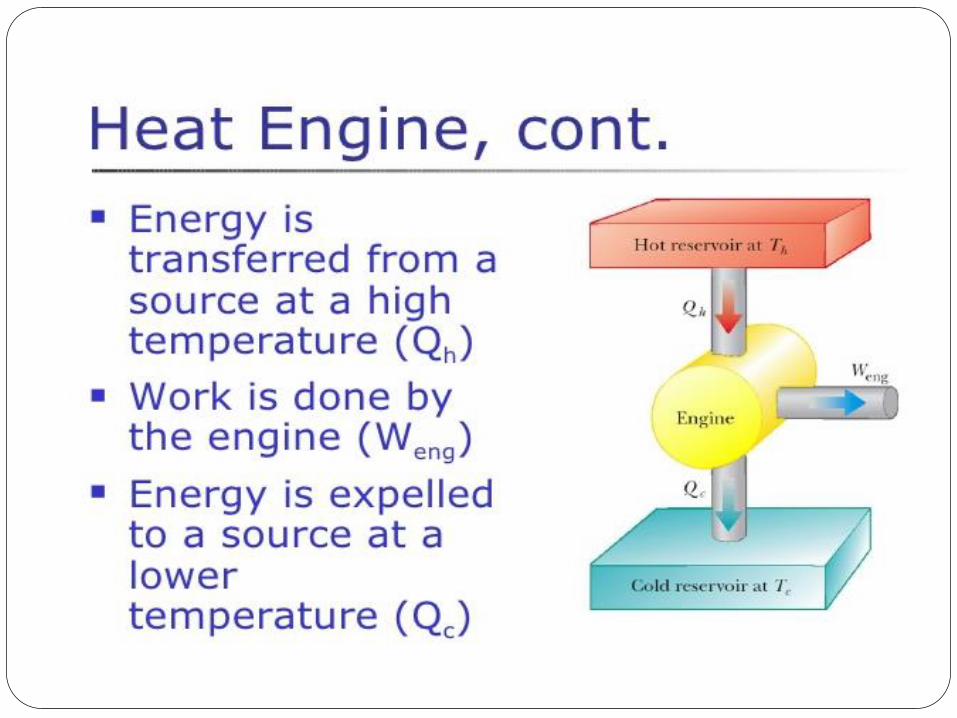
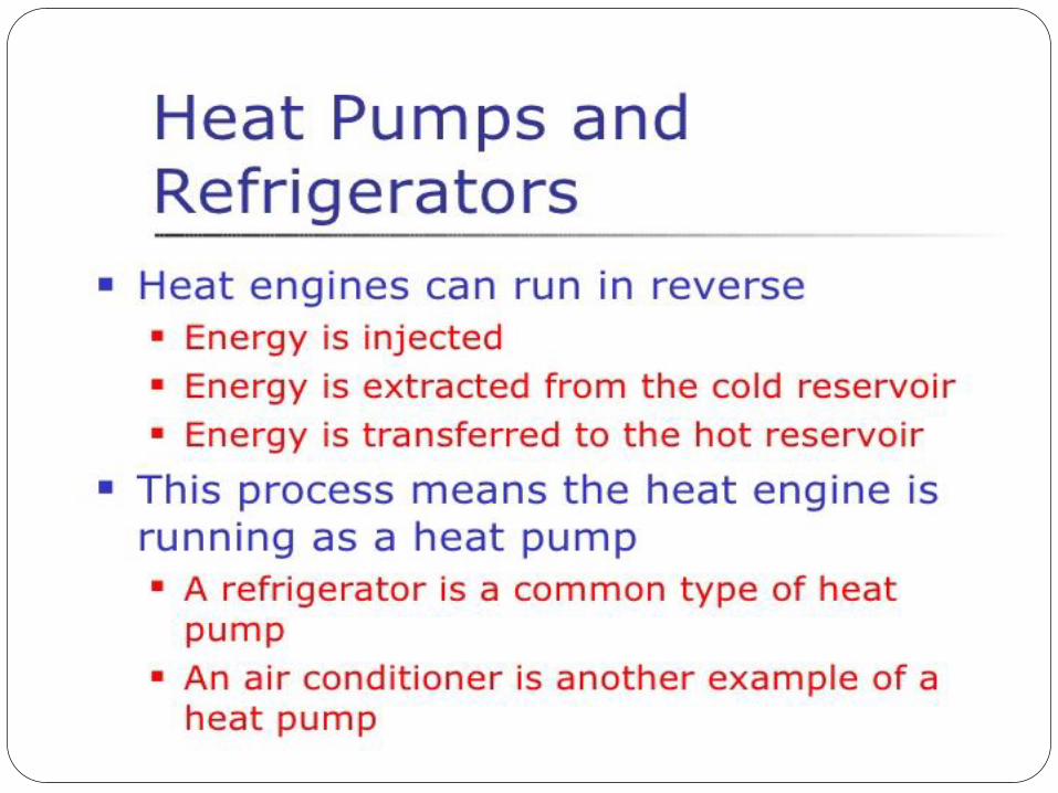
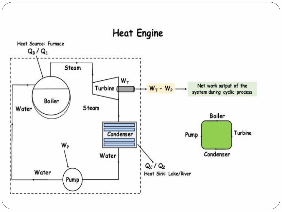
4.4.3. Heat engines, Refrigerators, Heat pumps: A heat engine may be defined as a device that operates in a thermodynamic cycle and does a certain amount of net positive work through the transfer of heat from a high temperature body to a low temperature body. A steam power plant is an example of a heat engine.
A refrigerator may be defined as a device that operates in a thermodynamic cycle and transfers a certain amount of heat from a body at a lower temperature to a body at a higher temperature by consuming certain amount of external work. Domestic refrigerators and room air conditioners are the examples. In a refrigerator, the required output is the heat extracted from the low temperature body.
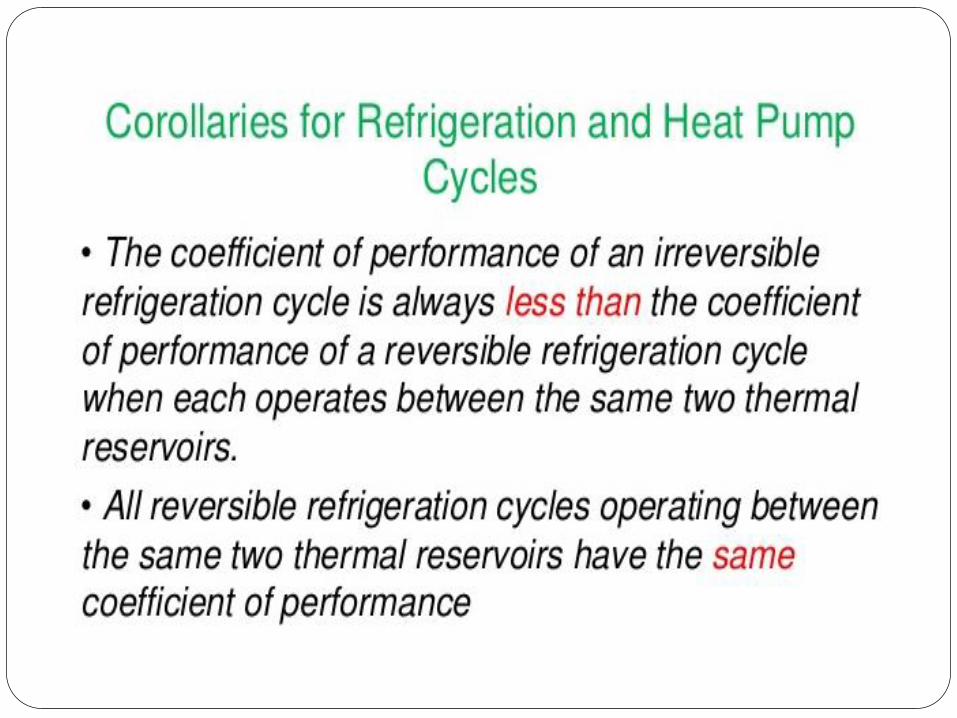
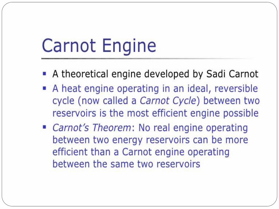
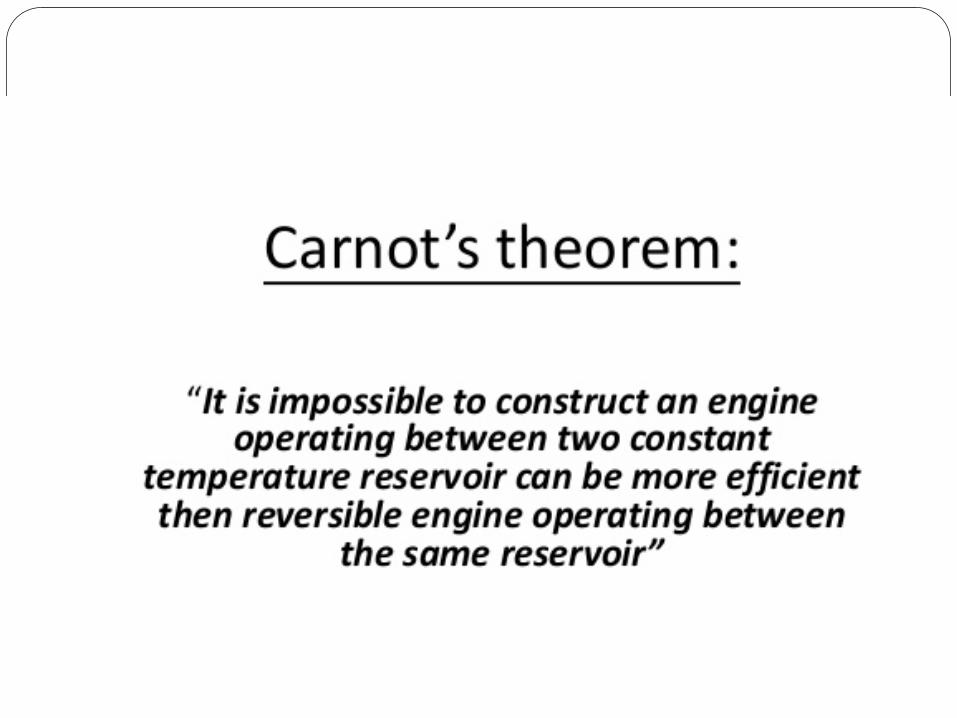
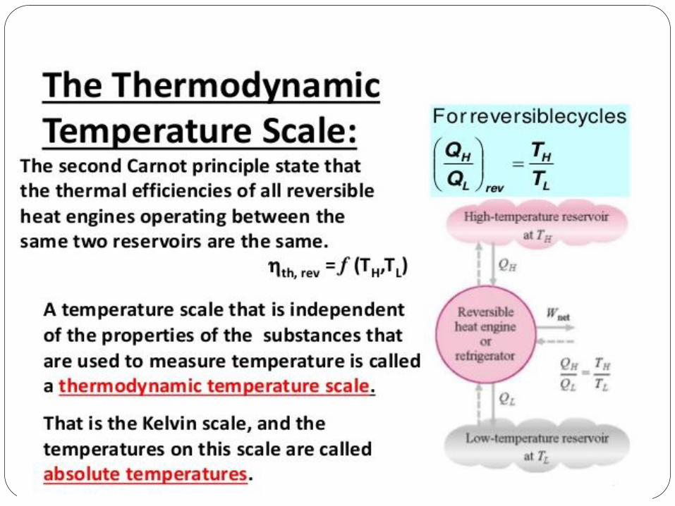
A heat pump is similar to a refrigerator, however, here the required output is the heat rejected to the high temperature body. Carnot’s theorems for heat engines: Theorem 1: It is impossible to construct a heat engine that operates between two thermal reservoirs and is more efficient than a reversible engine operating between the same two reservoirs. Theorem 2: All reversible heat engines operating between the same two thermal reservoirs have the same thermal efficiency. The two theorems can be proved by carrying out a thought experiment and with the help of second law. Carnot’s theorems can also be formed for refrigerators in a manner similar to heat engines. Carnot efficiency: The Carnot efficiencies are the efficiencies of completely reversible cycles operating between two thermal reservoirs. According to Carnot’s theorems, for any given two thermal reservoirs, the Carnot efficiency represents the maximum possible efficiency.
Version 1 ME, IIT Kharagpur 9

10
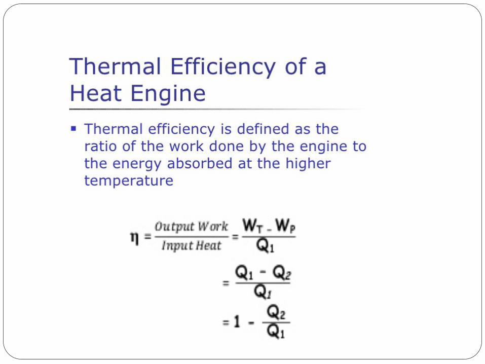
Thermal efficiency for a heat engine, ηHE is defined as:
H
C
H
cycleHE Q
Q1
QW
−==η (4.12)
where Wcycle is the net work output, QC and QH and are the heat rejected to the low temperature reservoir and heat added (heat input) from the high temperature reservoir, respectively.
It follows from Carnot’s theorems that for a reversible cycle (H
CQQ ) is a function of temperatures
of the two reservoirs only. i.e. H
CQQ )( , HC TTφ= .
If we choose the absolute (Kelvin) temperature scale then:
H
C
H
CTT
= (4.13)
hence, H
C
H
CHE,Carnot T
T1
1 −=−=η (4.14)
The efficiency of refrigerator and heat pump is called as Coefficient of Performance (COP). Similarly to heat engines, Carnot coefficient of performance for heat pump and refrigerators COPHP and COPR can be written as
CH
C
CH
C
cycle
CR,Carnot
CH
H
CH
H
cycle
HHP,Carnot
TTT
QQQ
WQ
COP
TTT
QQQ
WQ
COP
−===
−=
−==
−
(4.15)
where = work input to the reversible heat pump and refrigerator cycleW
HQ = heat transferred between the system and the hot reservoir = heat transferred between the system and cold reservoir CQ HT = temperature of the hot reservoir = temperature of the cold reservoir CT Clausius inequality: The Clausius inequality is a mathematical form of second law of thermodynamics for a closed system undergoing a cyclic process. It is given by:
0≤⎟⎠⎞
⎜⎝⎛∫
bTQδ (4.16)
In the above equation (4.16), Qδ represents the heat transfer at a part of the system boundary during a portion of the cycle, and T is the absolute temperature at that part of the boundary. The subscript “b” serves as a reminder that the integrand is evaluated at the boundary of the system executing the cycle. The equality applies when there are no internal irreversibilities as the
Version 1 ME, IIT Kharagpur 10
11
system executes the cycle, and inequality applies when there are internal irreversibilities are present. Entropy: As mentioned before, second law of thermodynamics introduces the property, entropy. It is a measure of amount of disorder in a system. It is also a measure of the extent to which the energy
of a system is unavailable. From Clausius inequality, 0TQ
rev,b
=∫ ⎟⎠⎞
⎜⎝⎛ δ for a reversible cycle. This
implies that the quantity rev,bT
Q⎟⎠⎞
⎜⎝⎛ δ must be a point function, hence a property of the system. This
property is named as ‘entropy’ by Clausius. The entropy change between any two equilibrium states 1 and 2 of a system is given by:
revTQSS
int
2
112 ⎟
⎟
⎠
⎞
⎜⎜
⎝
⎛=− ∫
δ (4.17)
Where , are the entropies at states 1 and 2. The subscript “int rev” is added as a reminder that the integration is carried out for any internally reversible process between the two states.
2S 1S
In general, for any process 1-2, the entropy change can be written as:
2
2 11 b
QS STδ⎛ ⎞
− ≥ ⎜⎝ ⎠∫ ⎟ (4.18)
The equality applies when there are no internal irreversibilities as the system executes the cycle, and inequality applies when there are internal irreversibilities are present. Equation (4.18) can also be written as:
σδ+⎟
⎟
⎠
⎞
⎜⎜
⎝
⎛=− ∫
bTQSS
2
112 (4.19)
where ⎩⎨⎧=>
systemtheinwithinpresentilitiesirreversibnosystemthewithinpresentilitiesirreversib
00
:σ
The above equation may be considered as an entropy balance equation for a closed system. If the end states are fixed, the entropy change on the left side of Eqn. (4.19) can be evaluated independently of the details of the process. The two terms on the right side depend explicitly on the nature of the process and cannot be determines solely from the knowledge of end states. The first term on the right side of the equation is interpreted as entropy transfer. The direction of entropy transfer is same as that of heat transfer. The entropy change of a system is not accounted solely by the entropy transfer. We have to include another term for entropy generation due to internal irreversibililies in the system. The second term in Eqn. (4.19) accounts for this, and is interpreted as entropy production. The value of entropy production cannot be negative. It can
Version 1 ME, IIT Kharagpur 11
12
have either zero or positive value. But the change in entropy of the system can be positive, negative, or zero.
⎪⎩
⎪⎨
⎧
<=>
−000
:12 SS (4.20)
Principle of increase of entropy: According the definition of an isolated system one can write:
0=Δ isolE (4.21) because no energy transfers takes place across its boundary. Thus the energy of the isolated system remains constant. An entropy balance for an isolated energy is written as:
isolb
isol TQS σδ
+⎟⎟
⎠
⎞
⎜⎜
⎝
⎛=Δ ∫
2
1 (4.22)
Since there are there are no energy transfers in an isolated system, the first term in the above equation is zero, hence the above equation reduces to:
0S isolisol >σ=Δ (4.23) where isolσ is the total amount of entropy produced within the isolated system, since this cannot be negative, it implies that the entropy of an isolated system can only increase. If we consider a combined system that includes the system and its surroundings, then the combined system becomes an isolated system. Then one can write:
0SS isolgssurroundinsystem >σ=Δ+Δ (4.24) since entropy is produced in all actual processes, only processes that can occur are those for which the entropy of the isolated system increases. Energy of an isolated system is conserved whereas entropy of an isolated system increases. This is called the principle of increase of entropy. Third law of thermodynamics: This law gives the definition of absolute value of entropy and also states that absolute zero cannot be achieved. Another version of this law is that “the entropy of perfect crystals is zero at absolute zero”. This statement is attributed to Plank. This is in line with the concept that entropy is a measure of disorder of the system. If ‘ω’ is the probability of achieving a particular state out of a large number of states; then entropy of the system is equal to ln(ω). The transitional movement of molecules ceases at absolute zero and position of atoms can be uniquely specified. In addition, if we have a perfect crystal, then all of its atoms are alike and their positions can be
Version 1 ME, IIT Kharagpur 12
Related Documents