Lecture : The ultrasound imaging system

Welcome message from author
This document is posted to help you gain knowledge. Please leave a comment to let me know what you think about it! Share it to your friends and learn new things together.
Transcript
Lecture: The ultrasound imaging system

The high-end ultrasound system from the outside
• High-quality screen
• Stereo speakers :-)
• Lots of buttons
• Small printer
• Probe connectors
• Input for ECG and auxillary pressure, and more
• Optical storage (VCR is finally out)

The high-end ultrasound imaging system
• Portable within buildings
• Weight ~ 200kg
• Multiple probe support
• Phased-array, (curved) linear-array, 2-D arrays, transesophagael (TEE)
• A range of imaging modalities
• 1-D / 2-D / 3-D / 4-D B-mode and Doppler imaging, duplex, triplex
• State-of-the art image quality and features
• Coded excitation, compound scanning, post-processing, real-time 3-D imaging
• High connectivity
• Patient reporting and data storage• PACS / DiCOM support• Support for legacy storage formats
Sequoia 512 iU2
2
Logic 9
Vivid E
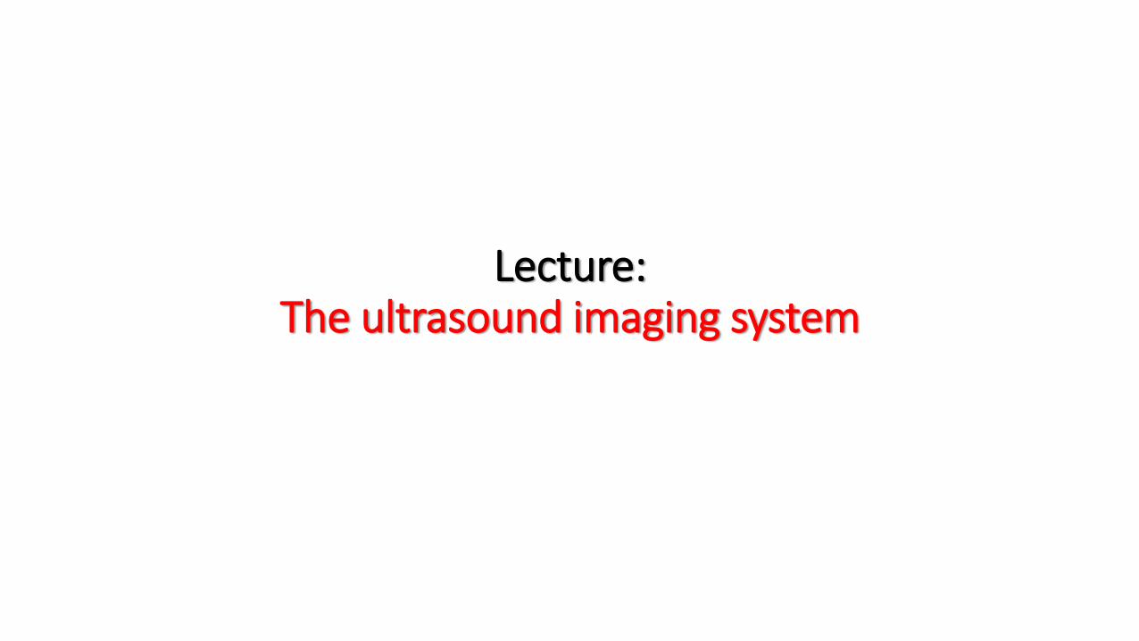
The compact ultrasound imaging system
• Portable lap-top sized scanner
• Weight ~ 5-10 kg• Battery operated
• Close to high-end functionality
• Multiple probe support
• Phased-array, (curved) linear-array, TEE
• Several modalities
• 2-D B-mode and Doppler imaging, duplex and triplex capabilities, 3-D (mechanical)
• Connectivity
• Patient reporting and data storage
• PACS / DiCOM support
Cypress
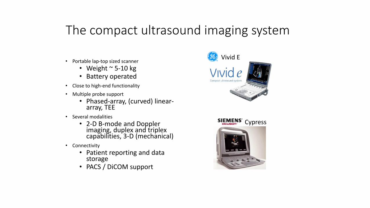
The hand-carried ultrasound system
• Very portable• Weight ~ 1-3 kg
• Simple functionality
• Fast boot-up time
• Varying probe support• Phased-array, (curved) linear-array
• The most important modalities• 2-D B-mode and color-Doppler
imaging
• Limited connectivity• Frame buffer
• Data transfer
Sonosite iLook
(2002)
SonoHeart Elite
(2002)
Philips OptiGo
(2001)
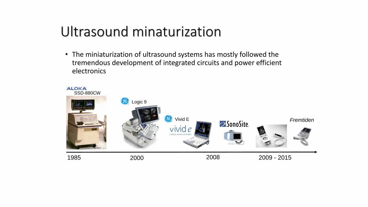
Ultrasound minaturization
• The miniaturization of ultrasound systems has mostly followed the tremendous development of integrated circuits and power efficient electronics
1985 2000 2009 - 2015
Logic 9
SSD-880CW
FremtidenVivid E
2008

Medical ultrasound imagingModalities
Time
De
pth
M-mode (motion) B-mode (brightness)

Medical ultrasound imagingModalities
PW-Doppler Color-DopplerH
as
tig
het
Tid
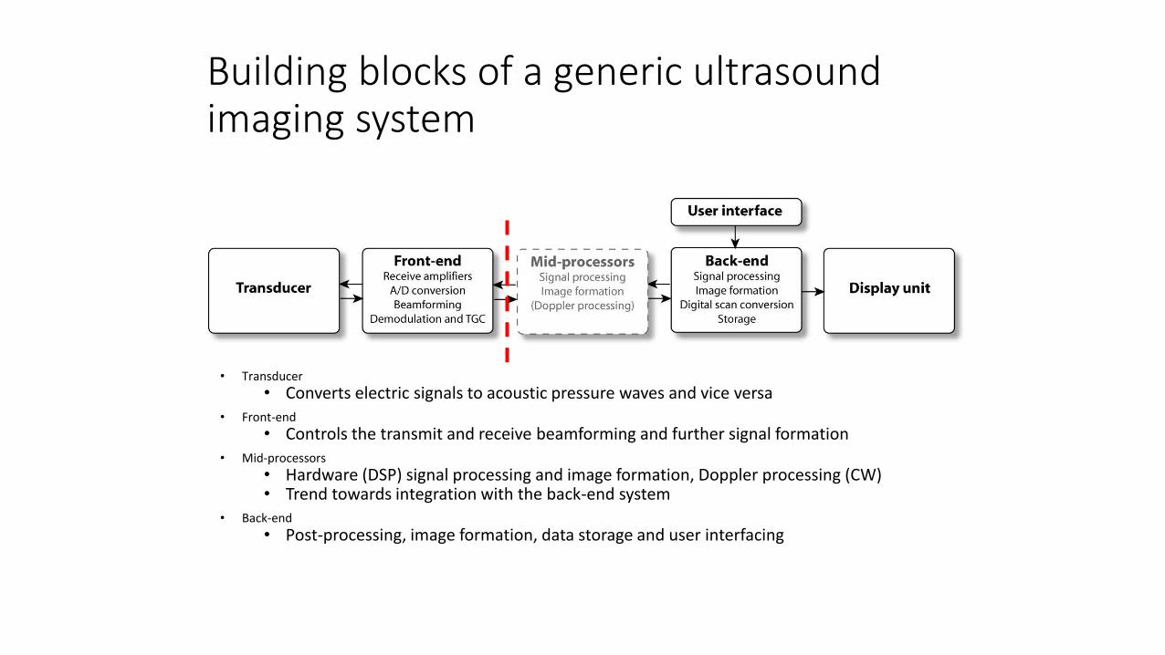
Building blocks of a generic ultrasound imaging system
• Transducer
• Converts electric signals to acoustic pressure waves and vice versa• Front-end
• Controls the transmit and receive beamforming and further signal formation• Mid-processors
• Hardware (DSP) signal processing and image formation, Doppler processing (CW)• Trend towards integration with the back-end system
• Back-end
• Post-processing, image formation, data storage and user interfacing
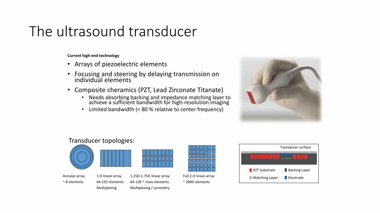
The ultrasound transducer
Current high-end technology
• Arrays of piezoelectric elements
• Focusing and steering by delaying transmission on individual elements
• Composite cheramics (PZT, Lead Zirconate Titanate)• Needs absorbing backing and impedance matching layer to
achieve a sufficient bandwidth for high-resolution imaging• Limited bandwidth (< 80 % relative to center frequency)
PZT Substrate Backing Layer
Matching Layer Electrode
. . .
Transducer surface
Annular array
~ 8 elements
1-D linear array
64-192 elements
Multiplexing
Full 2-D linear array
~ 2000 elements
1.25D-1.75D linear array
64-128 * rows elements
Multiplexing / symmetry
Transducer topologies:

Transducer shape and function
• Ultrasound transducers are optimized for a given frequency range
• Due to the fundamental resonance modes
• Due to frequency dependent attenuation
Transducers come in different shapes
• The acoustic window varies with application
• Typical applications
• Cardiac: phased-array, 1-5 MHz
• Abdominal: curvilinear array, 2-7 MHz
• Central vessels: Linear array, 5-10 MHz
• Peripheral: Linear array, 8-15 MHz
• Intravascular (catheter) > 20 MHz
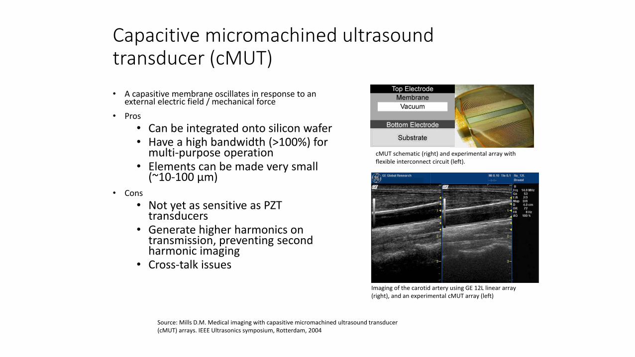
Capacitive micromachined ultrasound transducer (cMUT)
• A capasitive membrane oscillates in response to an external electric field / mechanical force
• Pros
• Can be integrated onto silicon wafer• Have a high bandwidth (>100%) for
multi-purpose operation• Elements can be made very small
(~10-100 μm)• Cons
• Not yet as sensitive as PZT transducers
• Generate higher harmonics on transmission, preventing second harmonic imaging
• Cross-talk issues
cMUT schematic (right) and experimental array with flexible interconnect circuit (left).
Imaging of the carotid artery using GE 12L linear array (right), and an experimental cMUT array (left)
Source: Mills D.M. Medical imaging with capasitive micromachined ultrasound transducer (cMUT) arrays. IEEE Ultrasonics symposium, Rotterdam, 2004
N
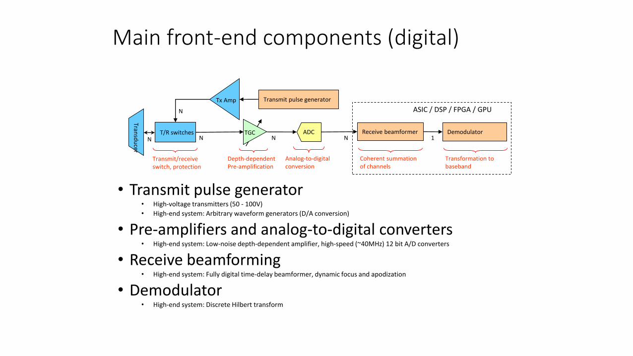
Main front-end components (digital)
• Transmit pulse generator• High-voltage transmitters (50 - 100V)
• High-end system: Arbitrary waveform generators (D/A conversion)
• Pre-amplifiers and analog-to-digital converters• High-end system: Low-noise depth-dependent amplifier, high-speed (~40MHz) 12 bit A/D converters
• Receive beamforming• High-end system: Fully digital time-delay beamformer, dynamic focus and apodization
• Demodulator• High-end system: Discrete Hilbert transform
Transd
ucer
T/R switches
Tx Amp Transmit pulse generator
ADC Receive beamformer
Depth-dependent Pre-amplification
Analog-to-digital conversion
DemodulatorNN 1
Coherent summation of channels
Transformation to baseband
N
N ASIC / DSP / FPGA / GPU
Transmit/receive switch, protection
TGC

Mid-processors
• Special purpose hardware components for signal processing and image formation
• Application specific integrated circuits (ASICs)
• Digital signal processors (DSPs)
• Field programmable gate arrays (FPGAs)
• Typical tasks:• Computationally intensive signal processing
• Image formation processing
• Doppler processingFigure: Mid-processors, special purpose hardware for signal processing and image formation
The rapid improvement in computational power of general purpose CPUs has moved an increasing number of mid-prosessing tasks to software in the back-end system

Back-end system
• Implemented using general purpose CPUs and systems
• Controls an increasing number of tasks:
• Software-based Doppler processing
• Post-processing of ultrasound data
• Image scan conversion
• Data storage and connectivity
• Latest developments• GPU (parallel) processing
• Software beamformingFigure: Plans for the Intel IA-32 system-on-chip. Dimensions ~ 4/4/0.4 cm (h/w/d), Pentium M processor, 600-1200 MHz, 13-22 W power consumption
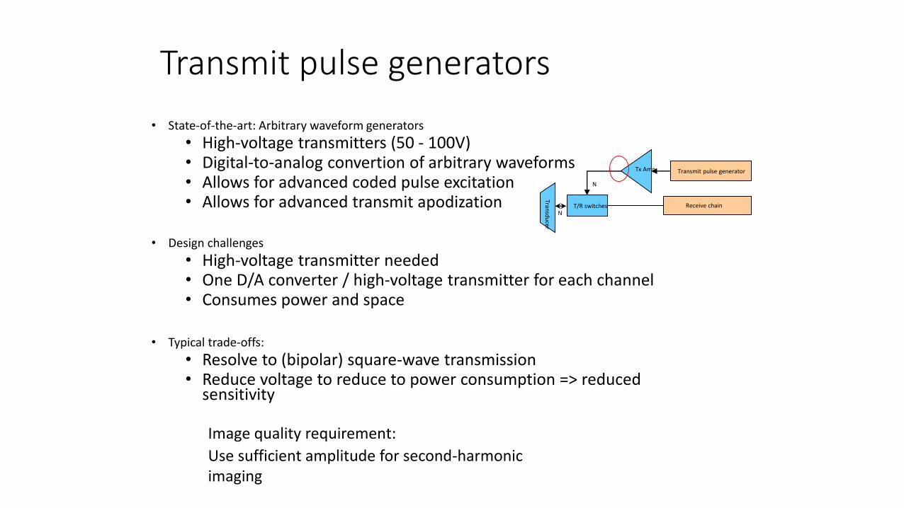
Transmit pulse generators
• State-of-the-art: Arbitrary waveform generators
• High-voltage transmitters (50 - 100V)• Digital-to-analog convertion of arbitrary waveforms• Allows for advanced coded pulse excitation• Allows for advanced transmit apodization
• Design challenges
• High-voltage transmitter needed• One D/A converter / high-voltage transmitter for each channel• Consumes power and space
• Typical trade-offs:
• Resolve to (bipolar) square-wave transmission• Reduce voltage to reduce to power consumption => reduced
sensitivity
Image quality requirement:
Use sufficient amplitude for second-harmonic imaging
T/R switches
Tx Amp Transmit pulse generator
N
N
Transd
ucer
Receive chain
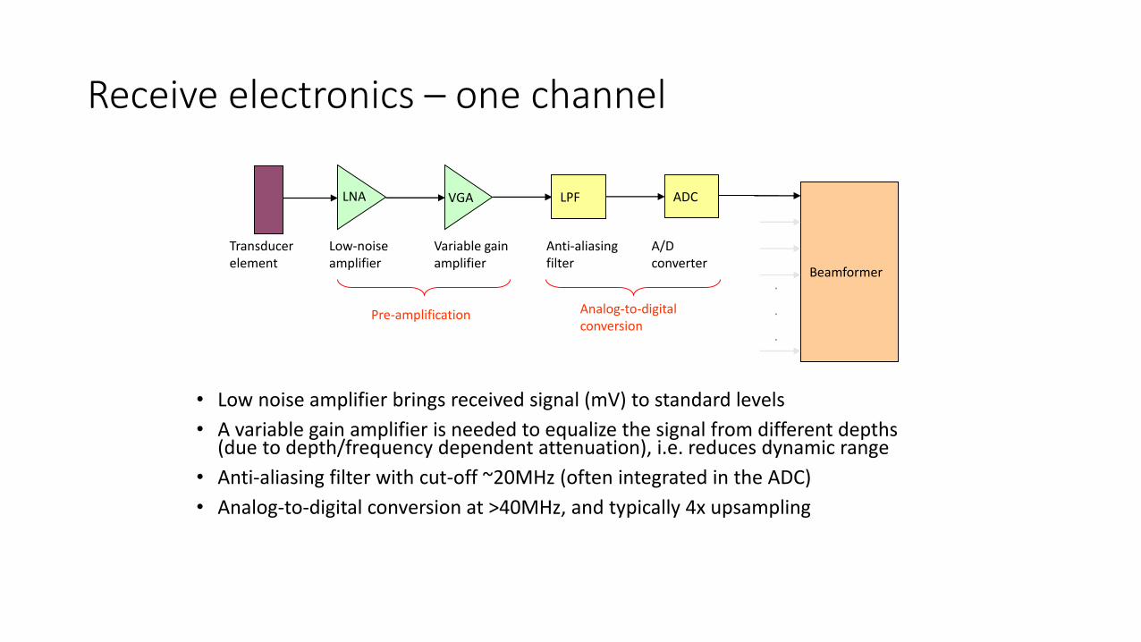
Receive electronics – one channel
• Low noise amplifier brings received signal (mV) to standard levels
• A variable gain amplifier is needed to equalize the signal from different depths(due to depth/frequency dependent attenuation), i.e. reduces dynamic range
• Anti-aliasing filter with cut-off ~20MHz (often integrated in the ADC)
• Analog-to-digital conversion at >40MHz, and typically 4x upsampling
LPF ADCLNA VGA
Transducer element
Anti-aliasing filter
A/D converter
Low-noise amplifier
Variable gain amplifier
Beamformer
Pre-amplification Analog-to-digital conversion
.
.
.

The dynamic range in ultrasound imaging
• The dynamic range of the received ultrasound echoes are influenced by
• Reflection losses, 20-30 dB, frequency dependent attenuation 1 dB/MHz·cm (pulse-echo)
• Example: Cardiac imaging• Freq. 2 MHz, depth 20 cm => 60-70 dB dynamic
range• Second-harmonic imaging => ~ 80-100 dB
Implications:
• Low-noise and depth dependent pre-amplifiers are needed to reduce the dynamic range
• High-resolution A/D-converters needed (at least 12 bit)
Depth
Transducer
Scattering sources
Source: Schafer M. E. and Lewin P. A. The influence of front-end hardware on digital ultrasonic imaging. IEEE Trans. Son. Ultrason., vol. 31, pp. 295-306, 1984

Channel count vs. image quality
• The channel count is proportional to the number of aperture elements
• Smaller elements are desired to increase the fundamental lateral resolution, and to avoid grating lobes
• Larger apertures are desired to obtain a narrow focus and to increase sensitivity
Annular array
~ 8 elements
1-D linear array
64-192 elements
1.25D-1.75D linear array
64-128 * rows elements
Transducer topologies:
Full 2-D linear array
~ 2000 elements
A/D
.
.
.
No
. of
chan
nel
s
Aperture vs. beam width
Depth
=> Trade-off between channel count and image quality
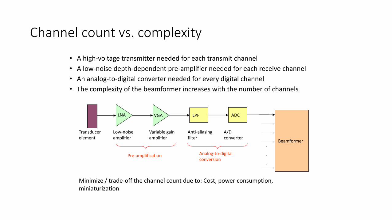
Channel count vs. complexity
• A high-voltage transmitter needed for each transmit channel
• A low-noise depth-dependent pre-amplifier needed for each receive channel
• An analog-to-digital converter needed for every digital channel
• The complexity of the beamformer increases with the number of channels
LPF ADCLNA VGA
Transducer element
Anti-aliasing filter
A/D converter
Low-noise amplifier
Variable gain amplifier
Beamformer
Pre-amplification Analog-to-digital conversion
.
.
.
Minimize / trade-off the channel count due to: Cost, power consumption, miniaturization
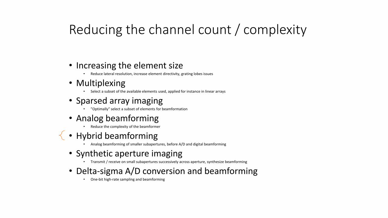
Reducing the channel count / complexity
• Increasing the element size• Reduce lateral resolution, increase element directivity, grating lobes issues
• Multiplexing• Select a subset of the available elements used, applied for instance in linear arrays
• Sparsed array imaging• ”Optimally” select a subset of elements for beamformation
• Analog beamforming• Reduce the complexity of the beamformer
• Hybrid beamforming• Analog beamforming of smaller subapertures, before A/D and digital beamforming
• Synthetic aperture imaging• Transmit / receive on small subapertures successively across aperture, synthesize beamforming
• Delta-sigma A/D conversion and beamforming• One-bit high-rate sampling and beamforming
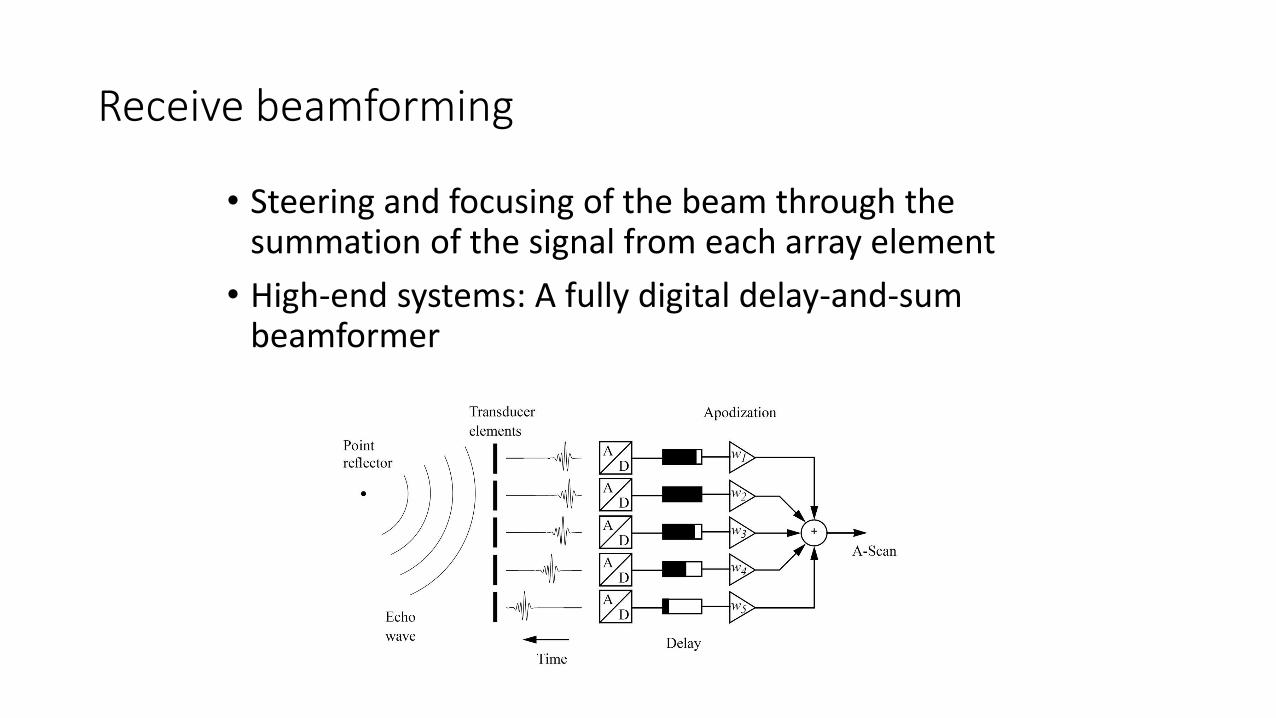
Receive beamforming
• Steering and focusing of the beam through the summation of the signal from each array element
• High-end systems: A fully digital delay-and-sum beamformer
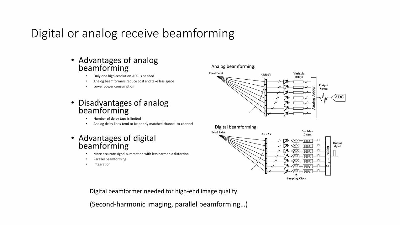
Digital or analog receive beamforming
• Advantages of analog beamforming
• Only one high-resolution ADC is needed
• Analog beamformers reduce cost and take less space
• Lower power consumption
• Disadvantages of analog beamforming
• Number of delay taps is limited
• Analog delay lines tend to be poorly matched channel-to-channel
• Advantages of digital beamforming
• More accurate signal summation with less harmonic distortion
• Parallel beamforming
• Integration
Digital beamforming:
Analog beamforming:
Digital beamformer needed for high-end image quality
(Second-harmonic imaging, parallel beamforming…)
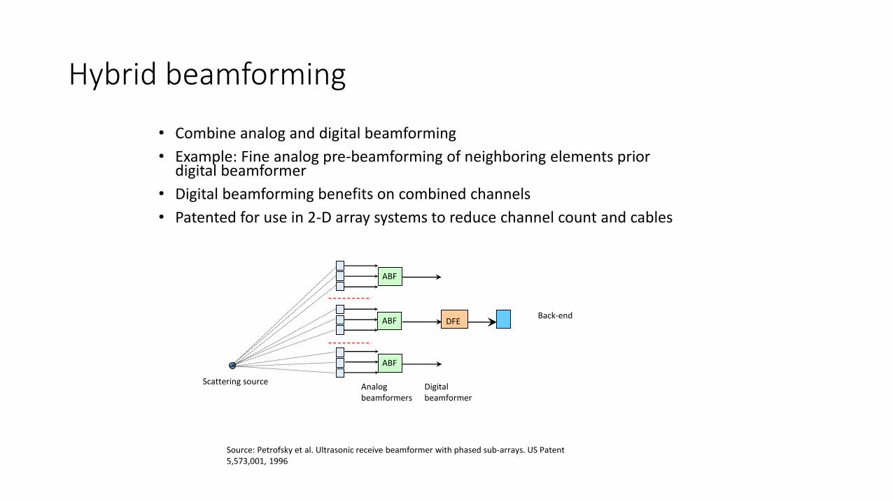
Hybrid beamforming
• Combine analog and digital beamforming
• Example: Fine analog pre-beamforming of neighboring elements prior digital beamformer
• Digital beamforming benefits on combined channels
• Patented for use in 2-D array systems to reduce channel count and cables
ABF
ABF
ABF
DFE
Analog beamformers
Digital beamformer
Back-end
Scattering source
Source: Petrofsky et al. Ultrasonic receive beamformer with phased sub-arrays. US Patent 5,573,001, 1996
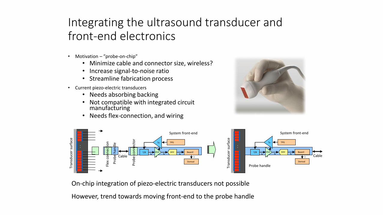
Integrating the ultrasound transducer and front-end electronics
• Motivation – ”probe-on-chip”
• Minimize cable and connector size, wireless?• Increase signal-to-noise ratio• Streamline fabrication process
• Current piezo-electric transducers
• Needs absorbing backing• Not compatible with integrated circuit
manufacturing• Needs flex-connection, and wiring
On-chip integration of piezo-electric transducers not possible
However, trend towards moving front-end to the probe handle
. .
Tran
sdu
cer
surf
ace
System front-end
T/R VGA
Tx TPG
ADC Beamf.
Demod
N N1
N
NCable
Pro
be
han
dle
Pro
be
con
nec
tor
Flex
co
nn
ecti
on
System front-end
T/R VGA
Tx TPG
ADC Beamf.
Demod
N N1
N
N
. .
Tran
sdu
cer
surf
ace
Cable
Probe handle

Synthetic aperture imaging
• Transmit and / or receive on single elements or subapertures successively across an aperture
• Reconstruct a high-resolution image by combining several low-resolution images
• Pros:• Reduced number of high-voltage transmit channels and / or receive channels
• An increased frame rate and dynamic focus on both transmit and receive can be achieved
• Cons:• Reduced sensitivity and spatial resolution
• Suceptible to motion artifacts
• Computationally demanding with large memory requirements
Sources:
Karaman et al. Synthetic Aperture Imaging for Small Scale Systems. IEEE Trans. on Ultrason., Ferroelect., and Freq. Contr., vol. 42, May 1995
Kim J-J. and Song T.K. Real-Time High-Resolution 3D Imaging Method Using 2D Phased Arrays Based on Sparse Synthetic Focusing Technique. IEEE Ultrasonics symposium proceedings, 2006
Coherently combine images from several low resolution emissions to produce final image
Related Documents