J.W. Morris, Jr. University of California, Berkeley MSE 200A Fall, 2008 Environmental Interactions • Chemical reaction between the material and its environment • Beneficial interactions: materials processing – Carburization and nitriding hardens for wear resistance – “Doping” adds electrically active species – Interfacial compounds are used as diffusion barriers • Harmful interactions – Oxidation • Materials “burn” slowly at high T – Corrosion • Electrochemical reactions oxidize near room temperature

Welcome message from author
This document is posted to help you gain knowledge. Please leave a comment to let me know what you think about it! Share it to your friends and learn new things together.
Transcript

J.W. Morris, Jr. University of California, Berkeley
MSE 200A Fall, 2008
Environmental Interactions
• Chemical reaction between the material and its environment
• Beneficial interactions: materials processing – Carburization and nitriding hardens for wear resistance – “Doping” adds electrically active species – Interfacial compounds are used as diffusion barriers
• Harmful interactions – Oxidation
• Materials “burn” slowly at high T – Corrosion
• Electrochemical reactions oxidize near room temperature

J.W. Morris, Jr. University of California, Berkeley
MSE 200A Fall, 2008
Mechanism of Parabolic Oxidation
• Diffusion through coherent oxide film – Metal is ordinarily more mobile, diffuses to oxidize at free surface – Growth is diffusion controlled – Thickness increases roughly as mean diffusion distance (<x> = √2Dt)
• Film diffusivity controls oxidation – Oxidation is a high-T phenomenon (rate increases exponentially with T) – Oxides with low D (high QD) are protective
• Film forms, but cannot growth
metal
oxide 2e - O O 2 O = MO
M ++ δ
€
δ = k t
€
k = Aexp− QD
kT

J.W. Morris, Jr. University of California, Berkeley
MSE 200A Fall, 2008
Mechanisms of Linear Oxidation
• Linear oxidation is the addition of many parabolic steps – Oxide does not fit perfectly on surface ⇒ mechanical strain – Strain increases as film thickens – At critical thickness, film ruptures, exposing fresh surface – Process repeats
• To suppress film rupture, suppress film growth – Minimize diffusion through film
δ
t

J.W. Morris, Jr. University of California, Berkeley
MSE 200A Fall, 2008
Engineering Oxidation Resistance: Alloying to Create Protective Films - Stainless Steel
• The corrosion rate of Fe decreases with Cr – Asymptotes at > 8% Cr (“stainless steel”)
• Preferential incorporation of Cr into the oxide film – Film is essentially Cr2O3 when Cr >8%.
• Protective film no better than protective oxide – Stainless steel liable to oxidation in presence of Cl (attacks Cr2O3) – Stainless steel oxidizes at sufficiently high T
ln (k)
Cr (wt%)5 10 15 20
• Influence of Cr on the oxidation rate of Fe
€
k = Aexp −QD
kT

J.W. Morris, Jr. University of California, Berkeley
MSE 200A Fall, 2008
Engineering Oxidation Resistance: Protective Coatings
• Protect high temperature structures with oxidation-resistant coatings – Ex: turbine blades in jet engines
• Properties required of a protective coating – Good oxidation resistance (Al, Cr) – Resistance to spall (fracture of coating)
• Matching coefficient of thermal expansion • Intermediate bonding layer
• Common choices: CoCrAlY, NiCrAlY – Co, Ni, Cr/Al ratio control adjust thermal expansion – Y improves adhesion at interface (often add additional “bonding layer”
protective coating
protected structure
bonding layer

J.W. Morris, Jr. University of California, Berkeley
MSE 200A Fall, 2008
Environmental Interactions: Aqueous Corrosion
• The primary source of degradation of structures – Particularly steel structures (“rust”)
• Corrosion is a low-temperature oxidation mechanism – Normal oxidation is prevented by the natural oxide coating – In corrosion, the protective coating does not automatically form – In the reaction: M++ + O= = MO
• The metal ions form at one location (the “anode”) • The oxygen forms at another (the “cathode”) • The two do not ordinarily develop a good protective coating
• Corrosion is an electrochemical process – Requires both electrical and chemical contact between
• Anode, where electrons and metal ions are generated • Cathode, where electrons are consumed, O= is generated

J.W. Morris, Jr. University of California, Berkeley
MSE 200A Fall, 2008
Electrochemistry: The Galvanic cell completes the circuit
• Two dissimilar metals (e.g., Zn, Cu) – Connected electrically (e.g., by a wire) – In contact with an electrolyte (e.g., ZnSO4|CuSO4) – React according to potential (Δϕ = ϕCu - ϕZn)
• Δϕ > 0 ⇒ Zn + 2Cu+ → Zn++ + Cu
• Complete circuit permits dissolution – Electrons swept from anode (Zn) to cathode (Cu) – Ions (SO4
=) swept from cathode to anode
Half-cell potentials:
€
φZn = φZn0 +
RT2Fln[Zn++]
€
φCu = φCu0 +
RT2Fln[Cu++]
Zn
Cu Zn ++
Cu +
SO 4 =
SO 4 =
V
e - Zn ÷ Zn ++ + 2 Cu+ + e- ↔ Cu
Zn dissolves, Cu is plated

J.W. Morris, Jr. University of California, Berkeley
MSE 200A Fall, 2008
The Galvanic Series in Seawater
Increasingly anodic ‘ TinMagnesium NickelMagnesium alloys Brasses (Cu-Zn)Zinc CopperAluminum Bronzes (Cu-Sn)Al-Cu alloys Silver soldersMild steel Nickel (passive)Wrought iron Monel (70Ni-30Cu)Cast iron Titanium18Cr-8Ni stainless steel (non-passivated) 18Cr-8Ni stainless steel (passive)50Pb-50Sn solder GoldLead Increasing cathodic ’
• The more anodic material in the couple is corroded
• Note: alloys are (generally) cathodic to pure metals – Free energy decreases on alloying

J.W. Morris, Jr. University of California, Berkeley
MSE 200A Fall, 2008
Concentration Cell
• Let a cell have Zn at both electrodes
• If the Zn concentration is different – A potential difference is developed – The side with the lower Zn concentration has lower potential – Lower Zn is the anode; is corroded
€
φZn = φZn0 +
RT2Fln[Zn++]
Zn ⇔ Zn++ + 2e-
€
Δφ =RT2Fln
Zn++[ ]1Zn++[ ]2

J.W. Morris, Jr. University of California, Berkeley
MSE 200A Fall, 2008
• Anode reactions: – Fe → Fe++ + 2e-
• Cathode reactions: – Normal cathode reaction:
2e- + 1/2O2 + H2O → 2(OH)-
– Acidic solution: 2e- + 2H+ → H2
– Strong potential: 2e- + H2O → 1/2H2 + (OH)-
• Oxidation reaction: – Fe++ + 2(OH)- → FeO + H2O – Note FeO may not coat surface
Cathode Reactions in Fe Corrosion
V
Fe Fe
H2O
OH- OH-
Fe++
Fe++

J.W. Morris, Jr. University of California, Berkeley
MSE 200A Fall, 2008
Galvanic Couples
• Dissimilar metal contact – Any two dissimilar conductors constitute a galvanic couple
• Microstructural heterogeneities – More stable grain or region (lowest free energy) is the cathode – High free energy due to:
• Mechanical deformation (defects) • Chemical heterogeneity • Phase or microstructural difference

J.W. Morris, Jr. University of California, Berkeley
MSE 200A Fall, 2008
Oxygen Concentration Cells
• Water immersion – [O2] decreases with depth – Cathode at surface – Anode at depth ⇒ Corrosion below water line
• Pitting corrosion – O2 denuded at base of pit – O2 replenished at surface – Anode at pit base ⇒ Corrosion deepens pit
€
φ =ϕ º+ RTnFln
O2[ ]1/ 2
OH−[ ]2
2e- + 1/2O2 + H2O ↔ 2OH- Cathode:

J.W. Morris, Jr. University of California, Berkeley
MSE 200A Fall, 2008
Crevice Corrosion
• Oxygen concentration cells develop at crevices – Rapid “crevice corrosion”
• Attacks rivets, screw heads, etc .
€
φ =ϕ º+ RTnFln
O2[ ]1/ 2
OH−[ ]2
2e- + 1/2O2 + H2O ↔ 2OH- Cathode:

J.W. Morris, Jr. University of California, Berkeley
MSE 200A Fall, 2008
Rate of Corrosion: Influence of Interface Polarization
• Rate of corrosion proportional to current density (i)
• Interface polarization – Ions produced too rapidly to diffuse away – Concentration build-up lowers Δφ – Steady state when Δφ = ρi (Ohm’s Law for Acathode = Aanode)
• ρ = electrical resistivity of conductor connecting anode to cathode
φ
log(i) i
Δφ=ρi
€
dmdt
= kiAI = iA
-

J.W. Morris, Jr. University of California, Berkeley
MSE 200A Fall, 2008
Rate of Corrosion: Effect of Anode Area
• Corrosion current determined by – Polarization determined by current density, determines φ = φ(i) – Actual current (I = iA) must be constant through circuit
• As anode area shrinks relative to cathode – Current density increases (corrosion rate increases) – Corrosion potential increases – Both change less strongly than area ratio
FeAnode electrolyte
Fe++
Fe++ OH-
OH-
cathode
I = iA
φ
log(I=iA)
Increasing AFe
Anode area increased Cathode area fixed
-

J.W. Morris, Jr. University of California, Berkeley
MSE 200A Fall, 2008
Protection Against Corrosion
• Break the circuit – Break electrical contact between metals – Break chemical contact with electrolyte
• Provide an alternate circuit – “cathodic protection”

J.W. Morris, Jr. University of California, Berkeley
MSE 200A Fall, 2008
Corrosion Protection: Breaking the Circuit
• Isolate anode from cathode – Insert insulator at dissimilar metal surface – Fe||Cu piping into a home – Teflon “sleeves” for rivets on aircraft
• Isolate metal from electrolyte by impermeable “paint” – Can paint either or both, but should paint cathode – Pin-hole break in anode risks catastrophic pitting corrosion – “Passivation”: material paints itself with oxide, like Al, Cr, stainless

J.W. Morris, Jr. University of California, Berkeley
MSE 200A Fall, 2008
Cathodic Protection
• Make the material the cathode
• Add a more anodic metal – “Sacrificial anode” – Must be in circuit
• Impose a reverse voltage – Reverse the sign of Δφ
FeMg
cathode
V
Fe
cathode
J.W. Morris, Jr. University of California, Berkeley
MSE 200A Fall, 2008
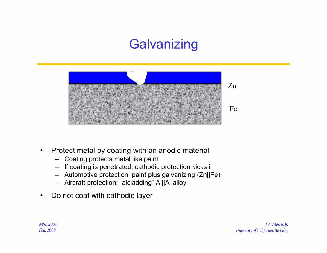
Galvanizing
• Protect metal by coating with an anodic material – Coating protects metal like paint – If coating is penetrated, cathodic protection kicks in – Automotive protection: paint plus galvanizing (Zn||Fe) – Aircraft protection: “alcladding” Al||Al alloy
• Do not coat with cathodic layer
Zn
Fe
J.W. Morris, Jr. University of California, Berkeley
MSE 200A Fall, 2008
Interfaces
• The engineering importance of surfaces – Wetting
• Frying pans and car waxes • Detergents • Lubricants
– Bonding • Glues • Solders
– Catalysis • Adsorption
– Capillarity • Tree sap and blood vessels
• The thermodynamics of surfaces – Surface tension – Wetting criteria

J.W. Morris, Jr. University of California, Berkeley
MSE 200A Fall, 2008
Interfaces and Wetting
• Conditions of equilibrium - open system – T, V (or A), {µ} fixed for interface
⇒ Ω(T,V,{µ}) = min = E - TS + ΣµkNk = - PV
• Assign excess quantities to surface
• ΩS(T,A,{µ}) = Ω - (Ωα + Ωβ )
transition shell dividing surface
€
ΩS =σA =min. (shape)
€
ΩS =σ =min. (state)
α
β

J.W. Morris, Jr. University of California, Berkeley
MSE 200A Fall, 2008
Wetting: The Contact Angle
• The “Young Equation” determines the “contact angle” – Balance of forces at the periphery of a drop on a rigid surface
• The wetting angle, θ ranges from 0 (wetting) to π (de-wetting)
€
cos(θ) =σ SV −σ SL
σ LV

J.W. Morris, Jr. University of California, Berkeley
MSE 200A Fall, 2008
Film Formation (Spreading)
• Spreading: LV+SL interfaces have lower energy than SV – Want for painting, coating, soldering, etc.
• To promote spreading – Raise σSV: e.g., clean the interface
• Flux in soldering removes oxides from surface – Lower σSL: e.g., include reactive species in L
• Sn in solder forms intermetallic compounds with Cu, Ni or Au – Lower σLV: e.g., add surfactant (species that adsorbs at LV interface)
• Flux in solder coats surface, lowers σLV
S
L V
€
σ SL +σ LV ≤σ SV

J.W. Morris, Jr. University of California, Berkeley
MSE 200A Fall, 2008
De-Wetting
• De-wetting: film of vapor preferred between S and L – LV+SV interfaces have lower energy than SL – Want for “non-stick” coatings (frying pans, car wax).
• To promote de-wetting – Lower σSV: e.g., add surfactants or low-σ coatings to solid
• Teflon on frying pans – Lower σLV: e.g., add surfactant (species that adsorbs at LV interface) – Raise σSL: e.g., remove any possible surfactants or reactive species
€
σ SV +σ LV ≤σ SLS
L V
Related Documents