Reinforced Concrete II Hashemite University Dr. Hazim Dwairi 1 The Hashemite University Department of Civil Engineering Lecture Lecture 9 9 – Footings Footings Dr Hazim Dwairi Dr Hazim Dwairi Reinforced Concrete II Reinforced Concrete II Dr. Hazim Dwairi Dr. Hazim Dwairi The Hashemite University The Hashemite University Dr. Hazim Dwairi Dr. Hazim Dwairi Footings Definition Footings Definition • Footings are structural members used to support Footings are structural members used to support columns and walls to transmit and distribute their columns and walls to transmit and distribute their columns and walls to transmit and distribute their columns and walls to transmit and distribute their loads to the soil in such a way that the load loads to the soil in such a way that the load bearing capacity of the soil is not exceeded, bearing capacity of the soil is not exceeded, excessive settlement, differential settlement, or excessive settlement, differential settlement, or rotation are prevented and adequate safety rotation are prevented and adequate safety against overturning or sliding is maintained. against overturning or sliding is maintained. Reinforced Concrete II Reinforced Concrete II • Since the soil is generally weaker than concrete Since the soil is generally weaker than concrete columns and walls, the contact area between the columns and walls, the contact area between the footing and the soil is much larger than between footing and the soil is much larger than between the supported members and footing. the supported members and footing. Dr. Hazim Dwairi Dr. Hazim Dwairi The Hashemite University The Hashemite University

Welcome message from author
This document is posted to help you gain knowledge. Please leave a comment to let me know what you think about it! Share it to your friends and learn new things together.
Transcript
Reinforced Concrete II Hashemite University
Dr. Hazim Dwairi 1
The Hashemite University
Department of Civil Engineering
Lecture Lecture 9 9 –– FootingsFootings
Dr Hazim DwairiDr Hazim Dwairi
Reinforced Concrete IIReinforced Concrete IIDr. Hazim DwairiDr. Hazim Dwairi The Hashemite UniversityThe Hashemite University
Dr. Hazim DwairiDr. Hazim Dwairi
Footings DefinitionFootings Definition
•• Footings are structural members used to support Footings are structural members used to support columns and walls to transmit and distribute theircolumns and walls to transmit and distribute theircolumns and walls to transmit and distribute their columns and walls to transmit and distribute their loads to the soil in such a way that the load loads to the soil in such a way that the load bearing capacity of the soil is not exceeded, bearing capacity of the soil is not exceeded, excessive settlement, differential settlement, or excessive settlement, differential settlement, or rotation are prevented and adequate safety rotation are prevented and adequate safety against overturning or sliding is maintained.against overturning or sliding is maintained.
Reinforced Concrete IIReinforced Concrete II
g g gg g g•• Since the soil is generally weaker than concrete Since the soil is generally weaker than concrete
columns and walls, the contact area between the columns and walls, the contact area between the footing and the soil is much larger than between footing and the soil is much larger than between the supported members and footing.the supported members and footing.
Dr. Hazim DwairiDr. Hazim Dwairi The Hashemite UniversityThe Hashemite University
Reinforced Concrete II Hashemite University
Dr. Hazim Dwairi 2
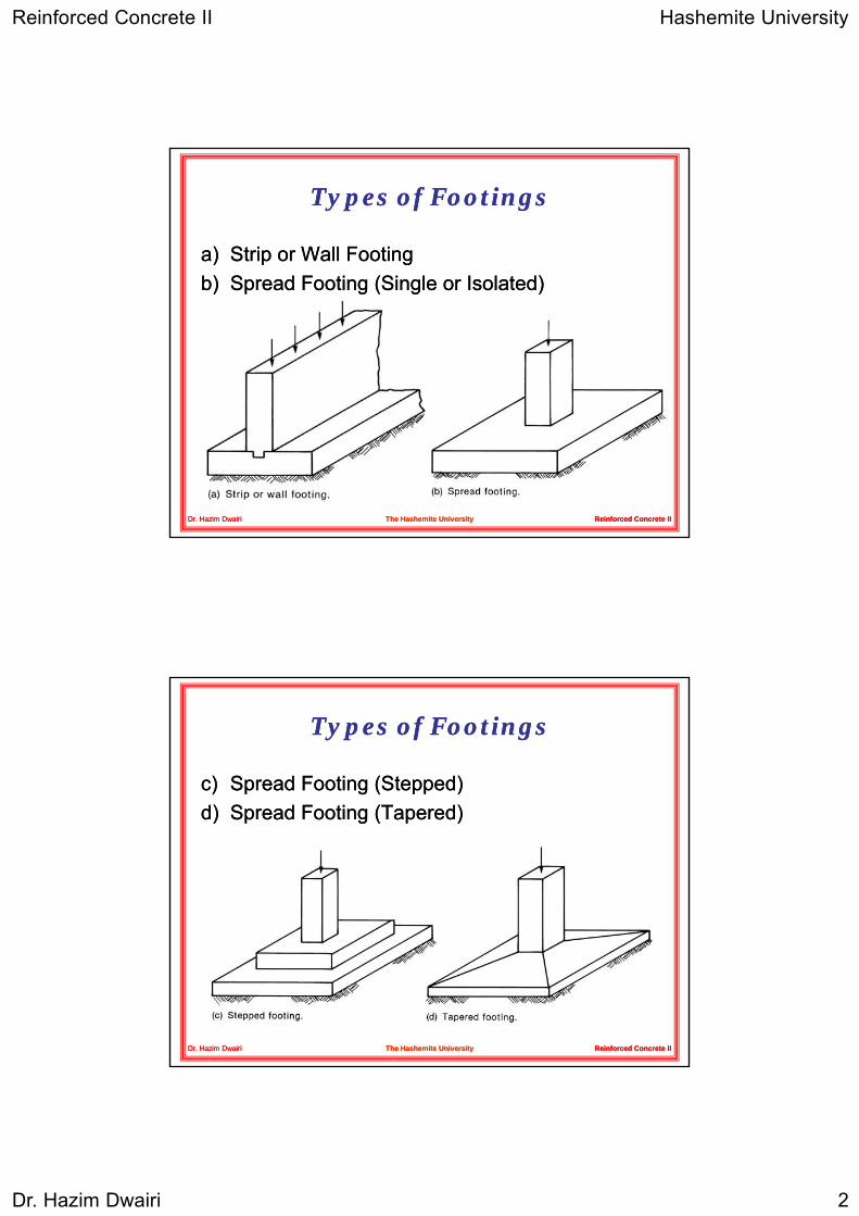
Types of FootingsTypes of Footings
a)a) Strip or Wall FootingStrip or Wall Footingb)b) S d F ti (Si l I l t d)S d F ti (Si l I l t d)b)b) Spread Footing (Single or Isolated)Spread Footing (Single or Isolated)
Reinforced Concrete IIReinforced Concrete IIDr. Hazim DwairiDr. Hazim Dwairi The Hashemite UniversityThe Hashemite University
Types of FootingsTypes of Footings
c)c) Spread Footing (Stepped)Spread Footing (Stepped)d)d) S d F ti (T d)S d F ti (T d)d)d) Spread Footing (Tapered)Spread Footing (Tapered)
Reinforced Concrete IIReinforced Concrete IIDr. Hazim DwairiDr. Hazim Dwairi The Hashemite UniversityThe Hashemite University
Reinforced Concrete II Hashemite University
Dr. Hazim Dwairi 3
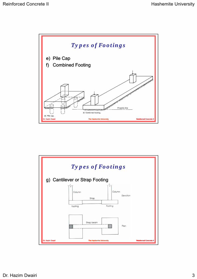
Types of FootingsTypes of Footings
e)e) Pile CapPile Capf)f) C bi d F tiC bi d F tif)f) Combined FootingCombined Footing
Reinforced Concrete IIReinforced Concrete IIDr. Hazim DwairiDr. Hazim Dwairi The Hashemite UniversityThe Hashemite University
Types of FootingsTypes of Footings
g)g) Cantilever or Strap FootingCantilever or Strap Footing
Reinforced Concrete IIReinforced Concrete IIDr. Hazim DwairiDr. Hazim Dwairi The Hashemite UniversityThe Hashemite University

Reinforced Concrete II Hashemite University
Dr. Hazim Dwairi 4
Types of FootingsTypes of Footings
h)h) Mat or Raft FootingMat or Raft Footing
Reinforced Concrete IIReinforced Concrete IIDr. Hazim DwairiDr. Hazim Dwairi The Hashemite UniversityThe Hashemite University
Distribution of Soil PressureDistribution of Soil Pressure
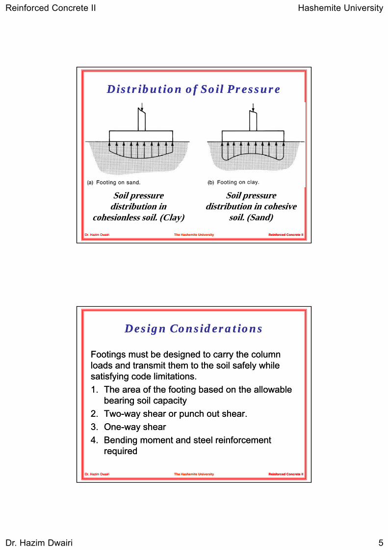
•• When the column load When the column load PP is applied on the is applied on the ppppcentroidcentroid of the footing, a of the footing, a uniform pressure is uniform pressure is assumed to develop on assumed to develop on the soil surface below the soil surface below the footing area.the footing area.
Reinforced Concrete IIReinforced Concrete IIDr. Hazim DwairiDr. Hazim Dwairi The Hashemite UniversityThe Hashemite University
•• However the actual distribution of the soil is not However the actual distribution of the soil is not uniform, but depends on may factors especially uniform, but depends on may factors especially the composition of the soil and degree of the composition of the soil and degree of flexibility of the footing.flexibility of the footing.
Reinforced Concrete II Hashemite University
Dr. Hazim Dwairi 5
Distribution of Soil PressureDistribution of Soil Pressure
Reinforced Concrete IIReinforced Concrete IIDr. Hazim DwairiDr. Hazim Dwairi The Hashemite UniversityThe Hashemite University
Soil pressure distribution in
cohesionless soil. (Clay)
Soil pressure distribution in cohesive
soil. (Sand)
Design ConsiderationsDesign Considerations
Footings must be designed to carry the column Footings must be designed to carry the column loads and transmit them to the soil safely whileloads and transmit them to the soil safely whileloads and transmit them to the soil safely while loads and transmit them to the soil safely while satisfying code limitations.satisfying code limitations.1.1. The area of the footing based on the allowable The area of the footing based on the allowable
bearing soil capacity bearing soil capacity 2.2. TwoTwo--way shear or punch out shear.way shear or punch out shear.33 OO hh
Reinforced Concrete IIReinforced Concrete II
3.3. OneOne--way shear way shear 4.4. Bending moment and steel reinforcement Bending moment and steel reinforcement
requiredrequired
Dr. Hazim DwairiDr. Hazim Dwairi The Hashemite UniversityThe Hashemite University
Reinforced Concrete II Hashemite University
Dr. Hazim Dwairi 6
Design ConsiderationsDesign Considerations
Footings must be designed to carry the column Footings must be designed to carry the column loads and transmit them to the soil safely whileloads and transmit them to the soil safely whileloads and transmit them to the soil safely while loads and transmit them to the soil safely while satisfying code limitations.satisfying code limitations.1.1. Bearing capacity of columns at their baseBearing capacity of columns at their base2.2. Dowel requirementsDowel requirements3.3. Development length of barsDevelopment length of bars
Reinforced Concrete IIReinforced Concrete II
4.4. Differential settlementDifferential settlement
Dr. Hazim DwairiDr. Hazim Dwairi The Hashemite UniversityThe Hashemite University
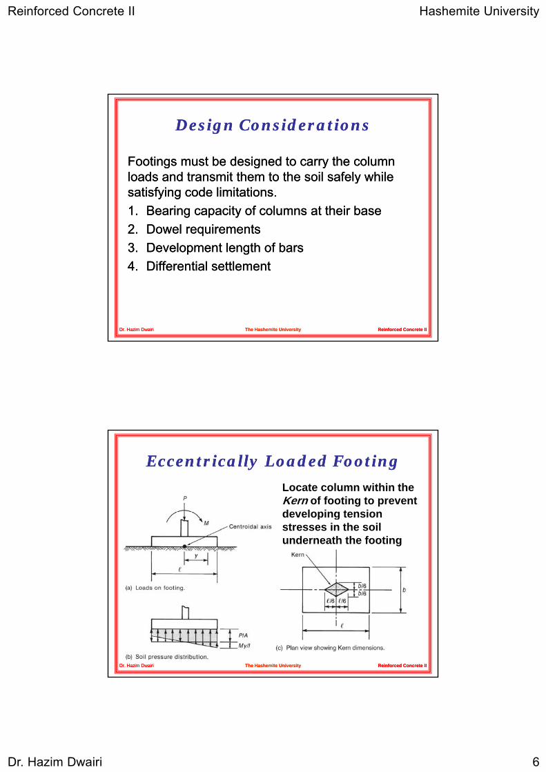
Eccentrically Loaded FootingEccentrically Loaded Footing
Locate column within the Kern of footing to prevent developing tensiondeveloping tension stresses in the soil underneath the footing
Reinforced Concrete IIReinforced Concrete IIDr. Hazim DwairiDr. Hazim Dwairi The Hashemite UniversityThe Hashemite University
Reinforced Concrete II Hashemite University
Dr. Hazim Dwairi 7
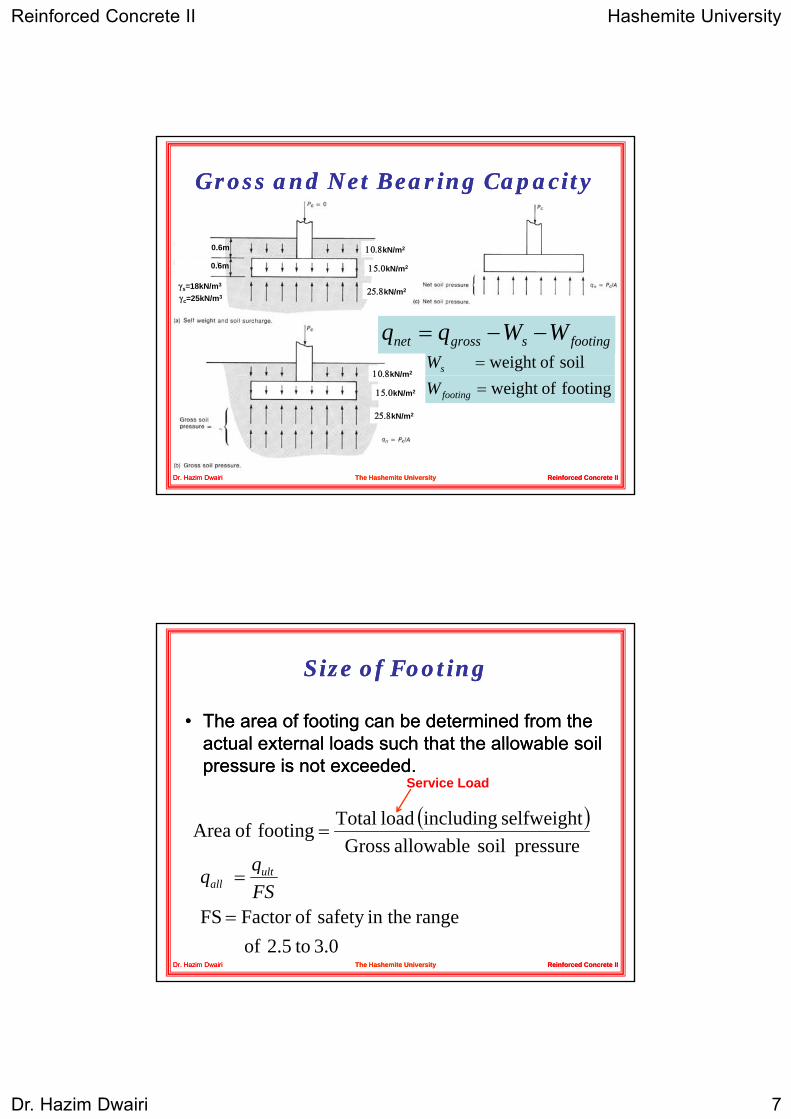
Gross and Net Bearing CapacityGross and Net Bearing Capacity
0.6m 10.8kN/m2
0.6m
γs=18kN/m3
γc=25kN/m3
15.0kN/m2
25.8kN/m2
10 8kN/m2
footingsgrossnet WWqq −−=soil ofweight =sW
Reinforced Concrete IIReinforced Concrete IIDr. Hazim DwairiDr. Hazim Dwairi The Hashemite UniversityThe Hashemite University
10.8kN/m
15.0kN/m2
25.8kN/m2
footing ofweight =footingW
Size of FootingSize of Footing
•• The area of footing can be determined from the The area of footing can be determined from the actual external loads such that the allowable soilactual external loads such that the allowable soilactual external loads such that the allowable soil actual external loads such that the allowable soil pressure is not exceeded.pressure is not exceeded.
( )pressure soil allowable Gross
selfweight including load Total footing of Area =
q
Service Load
Reinforced Concrete IIReinforced Concrete IIDr. Hazim DwairiDr. Hazim Dwairi The Hashemite UniversityThe Hashemite University
3.0 to2.5 of range in thesafety ofFactor FS =
=FSq q ult
all
Reinforced Concrete II Hashemite University
Dr. Hazim Dwairi 8
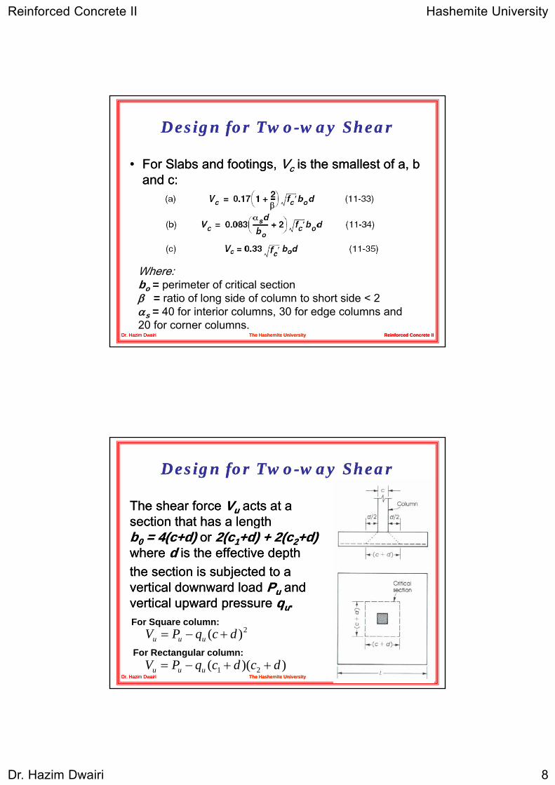
Design for TwoDesign for Two--way Shearway Shear
•• For Slabs and footings, For Slabs and footings, VVcc is the smallest of a, b is the smallest of a, b and c:and c:and c:and c:
Reinforced Concrete IIReinforced Concrete IIDr. Hazim DwairiDr. Hazim Dwairi The Hashemite UniversityThe Hashemite University
Where:bo = perimeter of critical sectionβ = ratio of long side of column to short side < 2αs = 40 for interior columns, 30 for edge columns and 20 for corner columns.
Design for TwoDesign for Two--way Shearway Shear
The shear force The shear force VVuu acts at a acts at a section that has a lengthsection that has a lengthsection that has a length section that has a length bb00 = = 44((c+dc+d) ) or or 22(c(c11+d) + +d) + 22(c(c22+d) +d) where where d d is the effective depthis the effective depththe section is subjected to a the section is subjected to a vertical downward load vertical downward load PPuu and and vertical upward pressurevertical upward pressure qq
Reinforced Concrete IIReinforced Concrete II
vertical upward pressurevertical upward pressure qquu..
Dr. Hazim DwairiDr. Hazim Dwairi The Hashemite UniversityThe Hashemite University
2)( dcqPV uuu +−=For Square column:
For Rectangular column:))(( 21 dcdcqPV uuu ++−=
Reinforced Concrete II Hashemite University
Dr. Hazim Dwairi 9
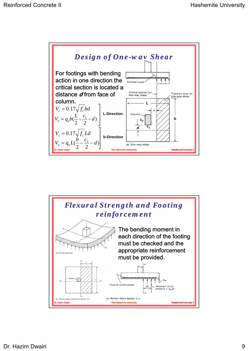
Design of OneDesign of One--way Shearway Shear
For footings with bending For footings with bending action in one direction theaction in one direction theaction in one direction the action in one direction the critical section is located a critical section is located a distance distance dd from face of from face of column. column.
bdfV cc'17.0=
b
L
)( 1 dcLbVL-Direction
Reinforced Concrete IIReinforced Concrete IIDr. Hazim DwairiDr. Hazim Dwairi The Hashemite UniversityThe Hashemite University
b
c1
c2)22
( 1 dbqV uu −−=
LdfV cc'17.0=
)22
( 2 dcbLqV uu −−=b-Direction
d
Flexural Strength and Footing Flexural Strength and Footing reinforcement reinforcement
The bending moment in The bending moment in each direction of the footing each direction of the footing must be checked and the must be checked and the appropriate reinforcement appropriate reinforcement must be provided.must be provided.
Reinforced Concrete IIReinforced Concrete IIDr. Hazim DwairiDr. Hazim Dwairi The Hashemite UniversityThe Hashemite University
Reinforced Concrete II Hashemite University
Dr. Hazim Dwairi 10
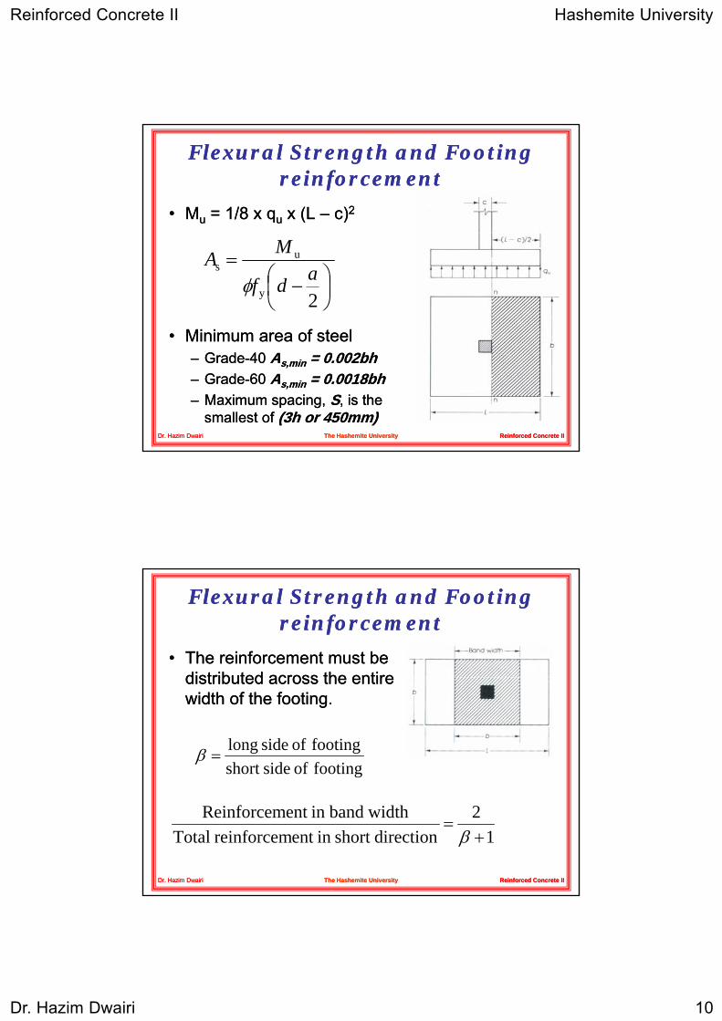
Flexural Strength and Footing Flexural Strength and Footing reinforcement reinforcement
•• MMuu = = 11//8 8 x x qquu x (L x (L –– c)c)22
•• Minimum area of steelMinimum area of steel
2y
us
⎟⎠⎞
⎜⎝⎛ −
=adf
MAφ
Reinforced Concrete IIReinforced Concrete II
–– GradeGrade--40 40 AAs,mins,min = = 00..002002bhbh–– GradeGrade--60 60 AAs,mins,min = = 00..00180018bhbh–– Maximum spacing, Maximum spacing, SS, is the , is the
smallest of smallest of ((33h or h or 450450mm)mm)Dr. Hazim DwairiDr. Hazim Dwairi The Hashemite UniversityThe Hashemite University
Flexural Strength and Footing Flexural Strength and Footing reinforcement reinforcement
•• The reinforcement must be The reinforcement must be distributed across the entiredistributed across the entiredistributed across the entire distributed across the entire width of the footing.width of the footing.
footing of sideshort footing of side long
=β
Reinforced Concrete IIReinforced Concrete IIDr. Hazim DwairiDr. Hazim Dwairi The Hashemite UniversityThe Hashemite University
12
directionshort in ent reinforcem Total widthbandin ent Reinforcem
+=β
Reinforced Concrete II Hashemite University
Dr. Hazim Dwairi 11
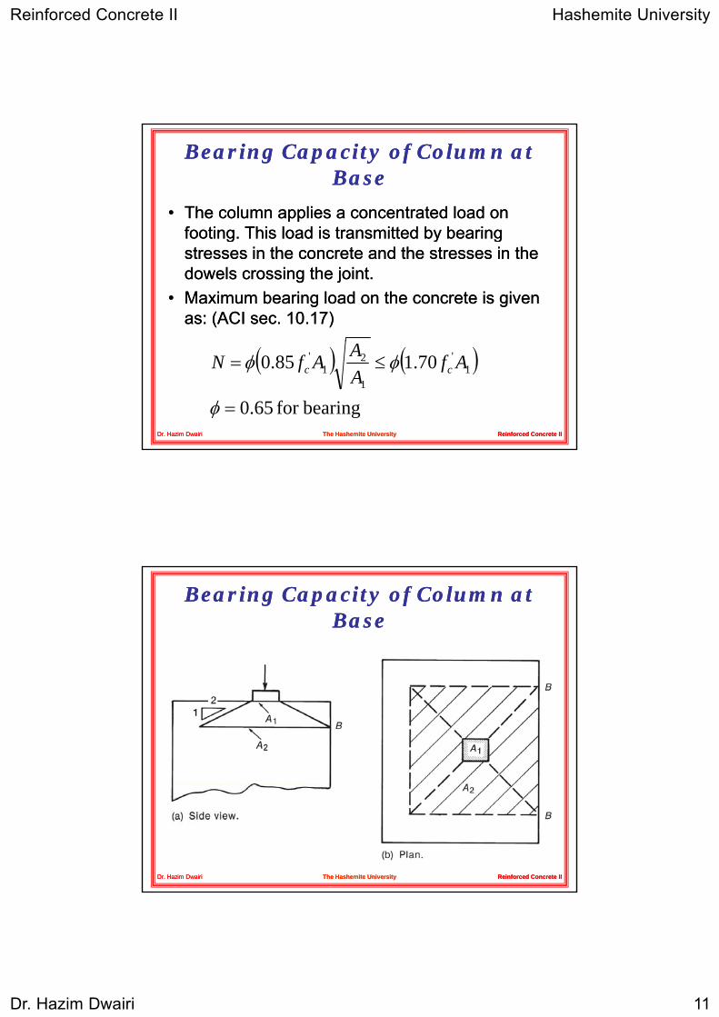
Bearing Capacity of Column at Bearing Capacity of Column at BaseBase
•• The column applies a concentrated load on The column applies a concentrated load on footing This load is transmitted by bearingfooting This load is transmitted by bearingfooting. This load is transmitted by bearing footing. This load is transmitted by bearing stresses in the concrete and the stresses in the stresses in the concrete and the stresses in the dowels crossing the joint.dowels crossing the joint.
•• Maximum bearing load on the concrete is given Maximum bearing load on the concrete is given as: (ACI sec. as: (ACI sec. 1010..1717))
Reinforced Concrete IIReinforced Concrete IIDr. Hazim DwairiDr. Hazim Dwairi The Hashemite UniversityThe Hashemite University
( ) ( )bearingfor 0.65
70.185.0 1'
1
21
'
=
≤=
φ
φφ AfAAAfN cc
Bearing Capacity of Column at Bearing Capacity of Column at BaseBase
Reinforced Concrete IIReinforced Concrete IIDr. Hazim DwairiDr. Hazim Dwairi The Hashemite UniversityThe Hashemite University
Reinforced Concrete II Hashemite University
Dr. Hazim Dwairi 12
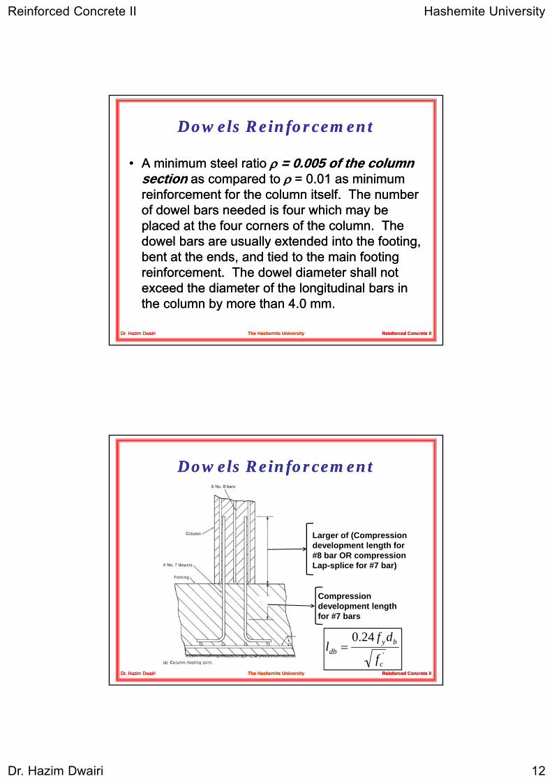
Dowels ReinforcementDowels Reinforcement
•• A minimum steel ratio A minimum steel ratio ρρ = = 00..005 005 of the column of the column sectionsection as compared toas compared to ρρ == 00 0101 as minimumas minimumsectionsection as compared to as compared to ρρ = = 00..01 01 as minimum as minimum reinforcement for the column itself. The number reinforcement for the column itself. The number of dowel bars needed is four which may be of dowel bars needed is four which may be placed at the four corners of the column. The placed at the four corners of the column. The dowel bars are usually extended into the footing, dowel bars are usually extended into the footing, bent at the ends, and tied to the main footing bent at the ends, and tied to the main footing
Reinforced Concrete IIReinforced Concrete II
, g, greinforcement. The dowel diameter shall not reinforcement. The dowel diameter shall not exceed the diameter of the longitudinal bars in exceed the diameter of the longitudinal bars in the column by more than the column by more than 44..0 0 mm.mm.
Dr. Hazim DwairiDr. Hazim Dwairi The Hashemite UniversityThe Hashemite University
Dowels ReinforcementDowels Reinforcement
Compression
Larger of (Compression development length for #8 bar OR compression Lap-splice for #7 bar)
Reinforced Concrete IIReinforced Concrete IIDr. Hazim DwairiDr. Hazim Dwairi The Hashemite UniversityThe Hashemite University
'
24.0
c
bydb
f
dfl =
development length for #7 bars
Reinforced Concrete II Hashemite University
Dr. Hazim Dwairi 13
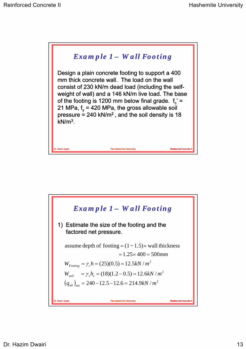
Example Example 1 1 –– Wall FootingWall Footing
Design a plain concrete footing to support a Design a plain concrete footing to support a 400 400 mm thick concrete wall The load on the wallmm thick concrete wall The load on the wallmm thick concrete wall. The load on the wall mm thick concrete wall. The load on the wall consist of consist of 230 230 kNkN/m dead load (including the self/m dead load (including the self--weight of wall) and a weight of wall) and a 146 146 kNkN/m live load. The base /m live load. The base of the footing is of the footing is 1200 1200 mm below final grade. mm below final grade. ffcc’ = ’ = 21 21 MPaMPa, , ffyy = = 420 420 MPaMPa, the gross allowable soil , the gross allowable soil pressure = pressure = 240 240 kNkN/m/m2 2 , and the soil density is , and the soil density is 18 18
Reinforced Concrete IIReinforced Concrete II
pp , y, ykNkN/m/m33..
Dr. Hazim DwairiDr. Hazim Dwairi The Hashemite UniversityThe Hashemite University
Example Example 1 1 –– Wall FootingWall Footing
1)1) Estimate the size of the footing and the Estimate the size of the footing and the factored net pressurefactored net pressurefactored net pressure.factored net pressure.
2/5.12)5.0)(25(50040025.1
thicknesswall1.5)~(1footing ofdepth assume
mkNhWmm
cFooting ===
=×=×=
γ
Reinforced Concrete IIReinforced Concrete IIDr. Hazim DwairiDr. Hazim Dwairi The Hashemite UniversityThe Hashemite University
( ) 2
2
/9.2146.125.12240
/6.12)5.02.1)(18(
mkNq
mkNhW
netall
sssoil
=−−=
=−== γ
Reinforced Concrete II Hashemite University
Dr. Hazim Dwairi 14
Example Example 1 1 –– Wall FootingWall Footing
:loadservice totalCalculateLLDLPservice +=
( ) 80.175.1376:strip) m-1(consider width footing Estimate
376 146230
mbUSEmPb service
service
=⇒===
=+=
Reinforced Concrete IIReinforced Concrete IIDr. Hazim DwairiDr. Hazim Dwairi The Hashemite UniversityThe Hashemite University
( )2/1.283
80.11466.12302.1
80.1 75.19.214
mkNq
mbUSEmq
b
u
netall
=×+×
=
⇒
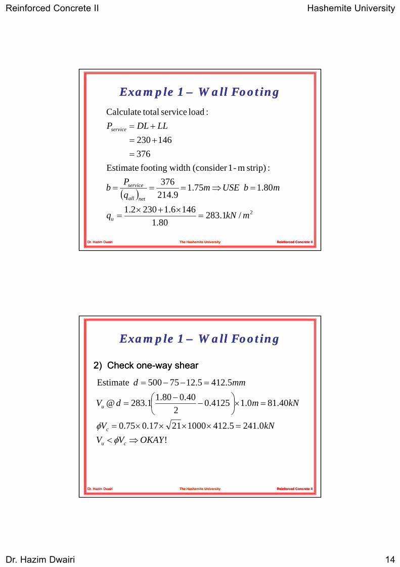
Example Example 1 1 –– Wall FootingWall Footing
2)2) Check oneCheck one--way shearway shear
!0.2415.41210002117.075.0
40.810.14125.02
40.080.11.283@
5.4125.1275500 Estimate
OKAYVVkNV
kNmdV
mmd
c
u
=××××=
=×⎟⎠⎞
⎜⎝⎛ −
−=
=−−=
φφ
Reinforced Concrete IIReinforced Concrete IIDr. Hazim DwairiDr. Hazim Dwairi The Hashemite UniversityThe Hashemite University
!OKAYVV cu ⇒<φ
Reinforced Concrete II Hashemite University
Dr. Hazim Dwairi 15
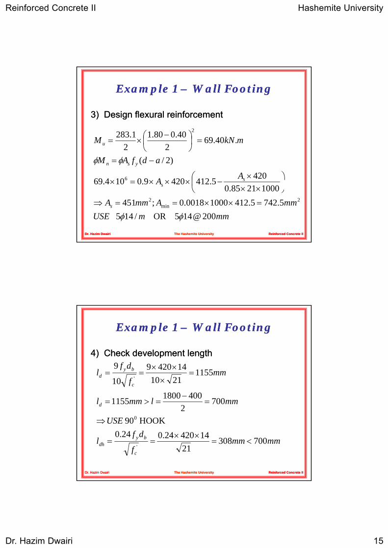
Example Example 1 1 –– Wall FootingWall Footing
3)3) Design flexural reinforcementDesign flexural reinforcement
AA
adfAM
mkNM
s
ysn
u
4205.4124209.0104.69
)2/(
.40.692
40.080.12
1.283
6
2
φφ
⎟⎞
⎜⎛ ×
−×××=×
−=
=⎟⎠⎞
⎜⎝⎛ −
×=
Reinforced Concrete IIReinforced Concrete IIDr. Hazim DwairiDr. Hazim Dwairi The Hashemite UniversityThe Hashemite University
mmmUSEmmAmmA
A
s
s
200@145 OR /145 5.7425.41210000018.0;451
10002185.05.4124209.0104.69
2min
2
φφ=××==⇒
⎟⎠
⎜⎝ ××
××××
Example Example 1 1 –– Wall FootingWall Footing
4)4) Check development lengthCheck development lengthdf 1442099
USE
mmlmml
mmf
dfl
d
c
byd
HOOK90
7002
40018001155
11552110
14420910
9
0
'
⇒
=−
=>=
=×
××==
Reinforced Concrete IIReinforced Concrete IIDr. Hazim DwairiDr. Hazim Dwairi The Hashemite UniversityThe Hashemite University
mmmmf
dfl
USE
c
bydh 700308
211442024.024.0
HOOK 90
'<=
××==
⇒
Reinforced Concrete II Hashemite University
Dr. Hazim Dwairi 16
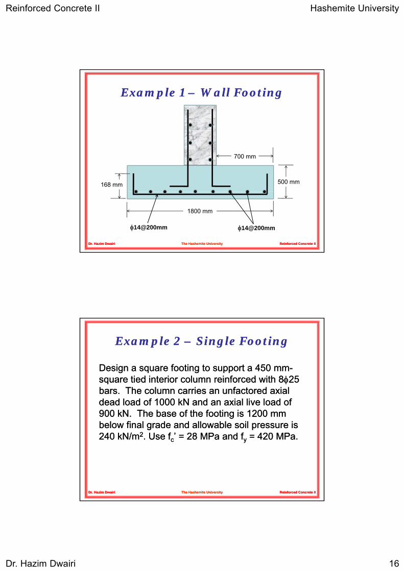
Example Example 1 1 –– Wall FootingWall Footing
700 mm
500 mm168 mm
Reinforced Concrete IIReinforced Concrete IIDr. Hazim DwairiDr. Hazim Dwairi The Hashemite UniversityThe Hashemite University
1800 mm
φ14@200mm φ14@200mm
Example Example 2 2 –– Single FootingSingle Footing
Design a square footing to support a Design a square footing to support a 450 450 mmmm--square tied interior column reinforced withsquare tied interior column reinforced with 88φφ2525square tied interior column reinforced with square tied interior column reinforced with 88φφ25 25 bars. The column carries an bars. The column carries an unfactoredunfactored axial axial dead load of dead load of 1000 1000 kNkN and an axial live load of and an axial live load of 900 900 kN.kN. The base of the footing is The base of the footing is 1200 1200 mm mm below final grade and allowable soil pressure is below final grade and allowable soil pressure is 240 240 kNkN/m/m22. Use . Use ffcc’ = ’ = 28 28 MPaMPa and and ffyy = = 420 420 MPaMPa..
Reinforced Concrete IIReinforced Concrete II
cc yy
Dr. Hazim DwairiDr. Hazim Dwairi The Hashemite UniversityThe Hashemite University
Reinforced Concrete II Hashemite University
Dr. Hazim Dwairi 17
Example Example 2 2 –– Single FootingSingle Footing
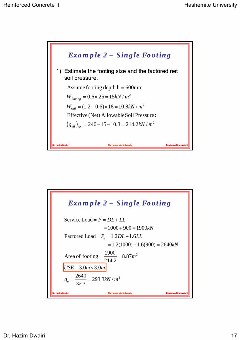
1)1) Estimate the footing size and the factored net Estimate the footing size and the factored net soil pressuresoil pressuresoil pressure.soil pressure.
2
2
PS ilAll bl(N t)Eff ti/8.1018)6.02.1(
/15256.0600mmhdepth footing Assume
mkNW
mkNW
soil
footing
=×−=
=×=
=
Reinforced Concrete IIReinforced Concrete IIDr. Hazim DwairiDr. Hazim Dwairi The Hashemite UniversityThe Hashemite University
( ) 2/2.2148.1015240:PressureSoilAllowable(Net) Effective
mkNq netall =−−=
Example Example 2 2 –– Single FootingSingle Footing
Load Service LLDLP +==
287.8214.21900footing of Area
2640)900(6.1)1000(2.1 6.12.1 Load Factored
19009001000
m
kNLLDLP
kN
u
==
=+=+==
=+=
Reinforced Concrete IIReinforced Concrete IIDr. Hazim DwairiDr. Hazim Dwairi The Hashemite UniversityThe Hashemite University
2/3.29333
26400.30.3
214.2
mkNq
mmUSE
u =×
=
×

Reinforced Concrete II Hashemite University
Dr. Hazim Dwairi 18
Example Example 2 2 –– Single FootingSingle Footing
2)2) Check thickness for twoCheck thickness for two--way shearway shear
⎪⎪⎪⎧
⎟⎞
⎜⎛
=⎟⎟⎠
⎞⎜⎜⎝
⎛+
=+==×−−=
d
dbfdbf
mmbPerimetermmdAverage
ococ
o
'' 51.02117.0
3750)5.487450(4 5.487255.175600
αβ
Reinforced Concrete IIReinforced Concrete IIDr. Hazim DwairiDr. Hazim Dwairi The Hashemite UniversityThe Hashemite University
⎪⎪⎪
⎩
⎪⎨ =⎟⎟
⎠
⎞⎜⎜⎝
⎛+=
dbf
dbfdbfb
dofmallestV
oc
ococo
sc
'
''
33.0
59.02083.0 s α
Example Example 2 2 –– Single FootingSingle Footing
( ) 3.23829375.02.2932640
2.23945.48737502833.075.02
u
c
kNV
kNVφ
=×−=
=××××=
3)3) Check oneCheck one--way shearway shear
( )OKAYshear way -Two cu
u
VV φ<
9.6923)4875.0245.0
23(3.293u kNV =×−−×=
Reinforced Concrete IIReinforced Concrete IIDr. Hazim DwairiDr. Hazim Dwairi The Hashemite UniversityThe Hashemite University
OKAYshear way -One 7.9865.48730002817.075.0
cu
c
VVkNV
φφ
<=××××=
Reinforced Concrete II Hashemite University
Dr. Hazim Dwairi 19
Example Example 2 2 –– Single FootingSingle Footing
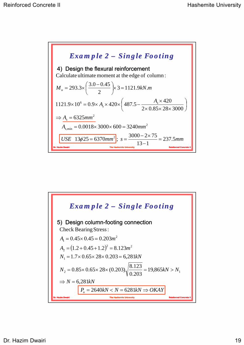
4)4) Design the flexural reinforcementDesign the flexural reinforcement:column of edge at themoment ultimate Calculate
A
AA
mkNM
ss
u
632530002885.02
4205.4874209.0109.1121
.9.112132
45.00.33.293
2
6 ⎟⎠⎞
⎜⎝⎛
××××
−×××=×
=×⎟⎠⎞
⎜⎝⎛ −
×=
Reinforced Concrete IIReinforced Concrete IIDr. Hazim DwairiDr. Hazim Dwairi The Hashemite UniversityThe Hashemite University
mmsmmUSE
mmA
mmA
s,
s
5.237113
7523000 ; 63702513
324060030000018.0
6325
2
2min
2
=−×−
==
=××=
=⇒
φ
Example Example 2 2 –– Single FootingSingle Footing
5)5) Design columnDesign column--footing connectionfooting connection:StressBearingCheck
( )kNN
mA
mA
=×××==++=
=×=
1238
281,6203.02865.07.1123.82.145.02.1
203.045.045.0:Stress BearingCheck
1
222
21
Reinforced Concrete IIReinforced Concrete IIDr. Hazim DwairiDr. Hazim Dwairi The Hashemite UniversityThe Hashemite University
OKAYkNNkNPkNN
NkNN
u ⇒=<==⇒
>=×××=
62812640 281,6
865,19203.0123.8)203.0(2865.085.0 12
Reinforced Concrete II Hashemite University
Dr. Hazim Dwairi 20
Example Example 2 2 –– Single FootingSingle Footing
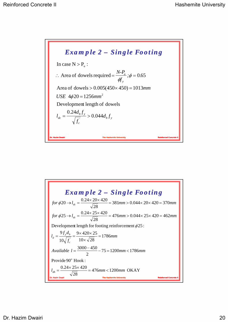
N-P 60i dd lfA
:PN caseIn u>
φy
u
mmUSEmm
.;f
N P
dowels oflength t Developmen1256204
1013)450450(005.0dowels of Area
650required dowels of Area
2=
=×>
==∴
φ
φφ
Reinforced Concrete IIReinforced Concrete IIDr. Hazim DwairiDr. Hazim Dwairi The Hashemite UniversityThe Hashemite University
yb
c
ybdc fd
f
fdl 044.0
24.0'
>=
Example Example 2 2 –– Single FootingSingle Footing
42025240
37042020044.038128
4202024.0 20 mmmmlfor dc
××
=××>=××
=→φ
4503000
17862810
25420910
9:25ent reinforcem footingfor length t Developmen
46242025044.047628
4202524.0 25
'mm
f
dfl
mmmmlfor
c
byd
dc
−
=×
××==
=××>=××
=→
φ
φ
Reinforced Concrete IIReinforced Concrete IIDr. Hazim DwairiDr. Hazim Dwairi The Hashemite UniversityThe Hashemite University
OKAY 120047628
4202524.0:Hook 90 Provide
17861200752
4503000
o
mmmml
mmmmlAvailable
dh <=××
=
<=−=
Reinforced Concrete II Hashemite University
Dr. Hazim Dwairi 21
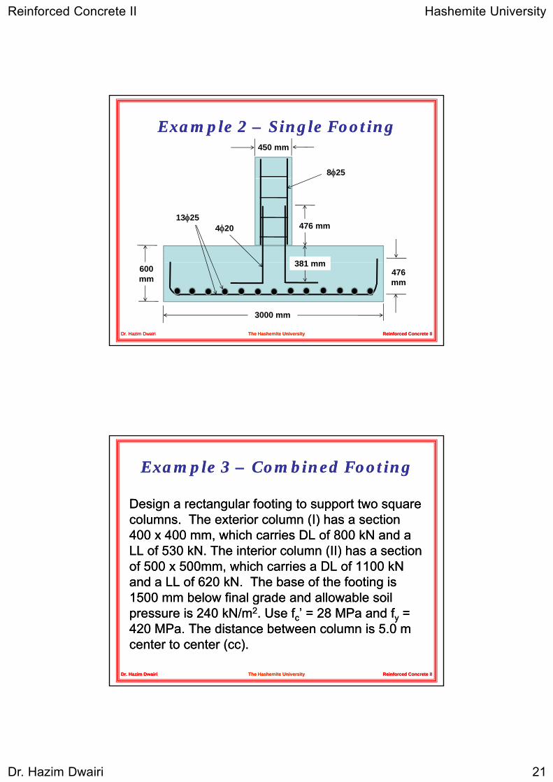
Example Example 2 2 –– Single FootingSingle Footing
8φ25
450 mm
476 mm
381 mm
13φ254φ20
Reinforced Concrete IIReinforced Concrete IIDr. Hazim DwairiDr. Hazim Dwairi The Hashemite UniversityThe Hashemite University
3000 mm
600 mm
476 mm
381 mm
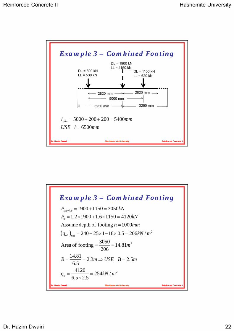
Example Example 3 3 –– Combined FootingCombined Footing
Design a rectangular footing to support two square Design a rectangular footing to support two square columns The exterior column (I) has a sectioncolumns The exterior column (I) has a sectioncolumns. The exterior column (I) has a section columns. The exterior column (I) has a section 400 400 x x 400 400 mm, which carries DL of mm, which carries DL of 800 800 kNkN and a and a LL of LL of 530 530 kN.kN. The interior column (II) has a section The interior column (II) has a section of of 500 500 x x 500500mm, which carries a DL of mm, which carries a DL of 1100 1100 kNkNand a LL of and a LL of 620 620 kN.kN. The base of the footing is The base of the footing is 1500 1500 mm below final grade and allowable soil mm below final grade and allowable soil
Reinforced Concrete IIReinforced Concrete II
ggpressure is pressure is 240 240 kNkN/m/m22. Use . Use ffcc’ = ’ = 28 28 MPaMPa and and ffyy = = 420 420 MPaMPa. The distance between column is . The distance between column is 55..0 0 m m center to center (cc).center to center (cc).
Dr. Hazim DwairiDr. Hazim Dwairi The Hashemite UniversityThe Hashemite University
Reinforced Concrete II Hashemite University
Dr. Hazim Dwairi 22
Example Example 3 3 –– Combined FootingCombined Footing
DL = 800 kNLL = 530 kN
DL = 1100 kNLL = 620 kN
DL = 1900 kNLL = 1150 kN
LL = 530 kN LL = 620 kN
5000 mm2820 mm 2820 mm
3250 mm3250 mm
Reinforced Concrete IIReinforced Concrete IIDr. Hazim DwairiDr. Hazim Dwairi The Hashemite UniversityThe Hashemite University
mmlUSEmml
6500 54002002005000min
==++=
Example Example 3 3 –– Combined FootingCombined Footing
412011506.119002.1305011501900
kNPkNP
u
service
=×+×==+=
( )2
2
8114
81.14206
3050footing of Area
/2065.0181252401000 footing ofdepth Assume
m
mkNqmmh
netall
u
==
=×−×−=
=
Reinforced Concrete IIReinforced Concrete IIDr. Hazim DwairiDr. Hazim Dwairi The Hashemite UniversityThe Hashemite University
2/2545.25.6
4120
5.2 3.25.681.14
mkNq
mBUSEmB
u =×
=
=⇒==

Reinforced Concrete II Hashemite University
Dr. Hazim Dwairi 23
Example Example 3 3 –– Combined FootingCombined Footing
6500 mm
2500 mm
2820
3250 3250
1080
1300 1400
1400
Reinforced Concrete IIReinforced Concrete IIDr. Hazim DwairiDr. Hazim Dwairi The Hashemite UniversityThe Hashemite University
500400230 8204550
Example Example 3 3 –– Combined FootingCombined Footing
)31081(254)5306180021(:Icolumn for shear way -Two90025751000 Average
V
mmd
×××+×=
=−−=
:IIcolumn for shear way -TwoOK! 428490047602833.075.0
4760)1300210802(1451
)3.108.1(254)5306.18002.1(
uc
o
u
VkNV
mmbkN
V
>=××××=
=×+×==
××−×+×=
φ
Reinforced Concrete IIReinforced Concrete IIDr. Hazim DwairiDr. Hazim Dwairi The Hashemite UniversityThe Hashemite UniversityOK! 504090056002833.075.0
5600)900500(41814
)9.05.0(254)6206.111002.1( 2
uc
o
u
VkNV
mmbkN
V
>=××××=
=+×==
+×−×+×=
φ
Reinforced Concrete II Hashemite University
Dr. Hazim Dwairi 24
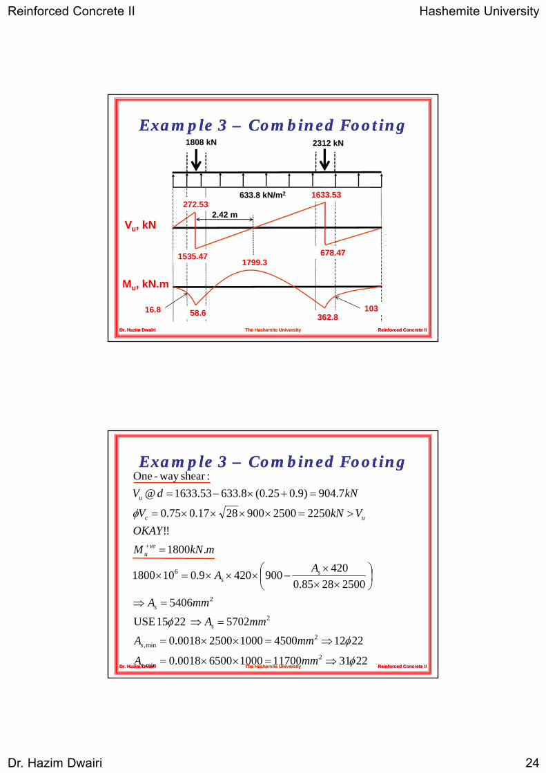
Example Example 3 3 –– Combined FootingCombined Footing1808 kN 2312 kN
633.8 kN/m2
272.53
1535.47
1633.53
678.47
2.42 mVu, kN
Reinforced Concrete IIReinforced Concrete IIDr. Hazim DwairiDr. Hazim Dwairi The Hashemite UniversityThe Hashemite University
535
58.6 362.8
1799.3
Mu, kN.m
16.8 103
Example Example 3 3 –– Combined FootingCombined Footing
2250250090028170750
7.904)9.025.0(8.63353.1633@:shearway -One
φ >=××××=
=+×−=
VkNV
kNdVu
25002885.04209004209.0101800
.1800!!
225025009002817.075.0
6
φ
⎟⎠⎞
⎜⎝⎛
×××
−×××=×
=
>=××××=
+
AA
mkNMOKAY
VkNV
ss
veu
uc
Reinforced Concrete IIReinforced Concrete IIDr. Hazim DwairiDr. Hazim Dwairi The Hashemite UniversityThe Hashemite University223111700100065000018.0
22124500100025000018.0
5702 2215 USE
5406
2min,
2min,
2
2
φ
φ
φ
⇒=××=
⇒=××=
=⇒
=⇒
mmA
mmA
mmA
mmA
s
s
s
s
Reinforced Concrete II Hashemite University
Dr. Hazim Dwairi 25
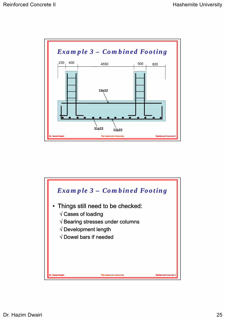
Example Example 3 3 –– Combined FootingCombined Footing
230 400 4550 500 820
15φ22
Reinforced Concrete IIReinforced Concrete IIDr. Hazim DwairiDr. Hazim Dwairi The Hashemite UniversityThe Hashemite University
12φ2231φ22
Example Example 3 3 –– Combined FootingCombined Footing
•• Things still need to be checked:Things still need to be checked:√√√√ Cases of loadingCases of loading√√ Bearing stresses under columnsBearing stresses under columns√√ Development lengthDevelopment length√√ Dowel bars if neededDowel bars if needed
Reinforced Concrete IIReinforced Concrete IIDr. Hazim DwairiDr. Hazim Dwairi The Hashemite UniversityThe Hashemite University
Related Documents