Lecture #8 Distributed Loads Reference Chapter 4, Section 9

Lecture #8 Distributed Loads Reference Chapter 4, Section 9.
Dec 17, 2015
Welcome message from author
This document is posted to help you gain knowledge. Please leave a comment to let me know what you think about it! Share it to your friends and learn new things together.
Transcript

Lecture #8
Distributed LoadsReference Chapter 4, Section 9
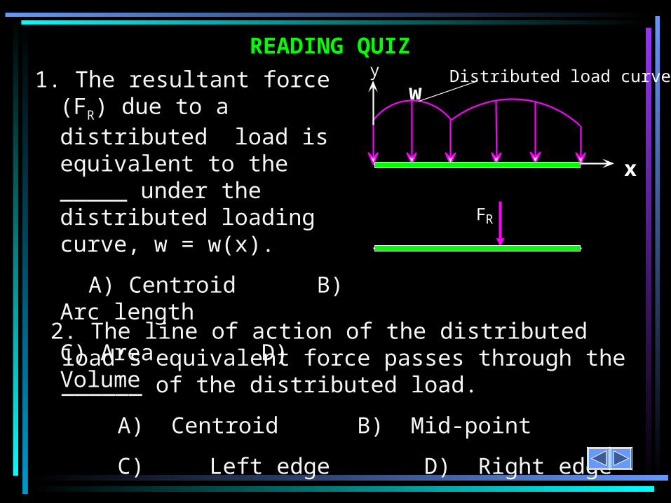
READING QUIZ
2. The line of action of the distributed load’s equivalent force passes through the ______ of the distributed load.
A) Centroid B) Mid-point
C) Left edge D) Right edge
1. The resultant force (FR) due to a distributed load is equivalent to the _____ under the distributed loading curve, w = w(x).
A) Centroid B) Arc length
C) Area D) Volume
x
w
FR
Distributed load curvey

APPLICATIONS
To analyze the load’s effect on the steel beams, it is often helpful to reduce this distributed load to a single force. How would you do this?
There is a bundle (called a bunk) of 2” x 4” boards stored on a storage rack. This lumber places a distributed load (due to the weight of the wood) on the beams holding the bunk.

APPLICATIONS (continued)
The uniform wind pressure is acting on a triangular sign (shown in light brown).
To be able to design the joint between the sign and the sign post, we need to determine a single equivalent resultant force and its location.
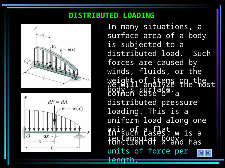
DISTRIBUTED LOADING
In such cases, w is a function of x and has units of force per length.
In many situations, a surface area of a body is subjected to a distributed load. Such forces are caused by winds, fluids, or the weight of items on the body’s surface.
We will analyze the most common case of a distributed pressure loading. This is a uniform load along one axis of a flat rectangular body.
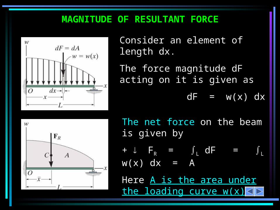
MAGNITUDE OF RESULTANT FORCE
The net force on the beam is given by
+ FR = L dF = L w(x) dx = A
Here A is the area under the loading curve w(x).
Consider an element of length dx.
The force magnitude dF acting on it is given as
dF = w(x) dx

LOCATION OF THE RESULTANT FORCE
The total moment about point O is given as
+ MRO = L x dF = L x w(x) dx
Assuming that FR acts at , it will produce the moment about point O as
+ MRO = ( ) (FR) = L w(x) dx
x
xx
The force dF will produce a moment of (x)(dF) about point O.
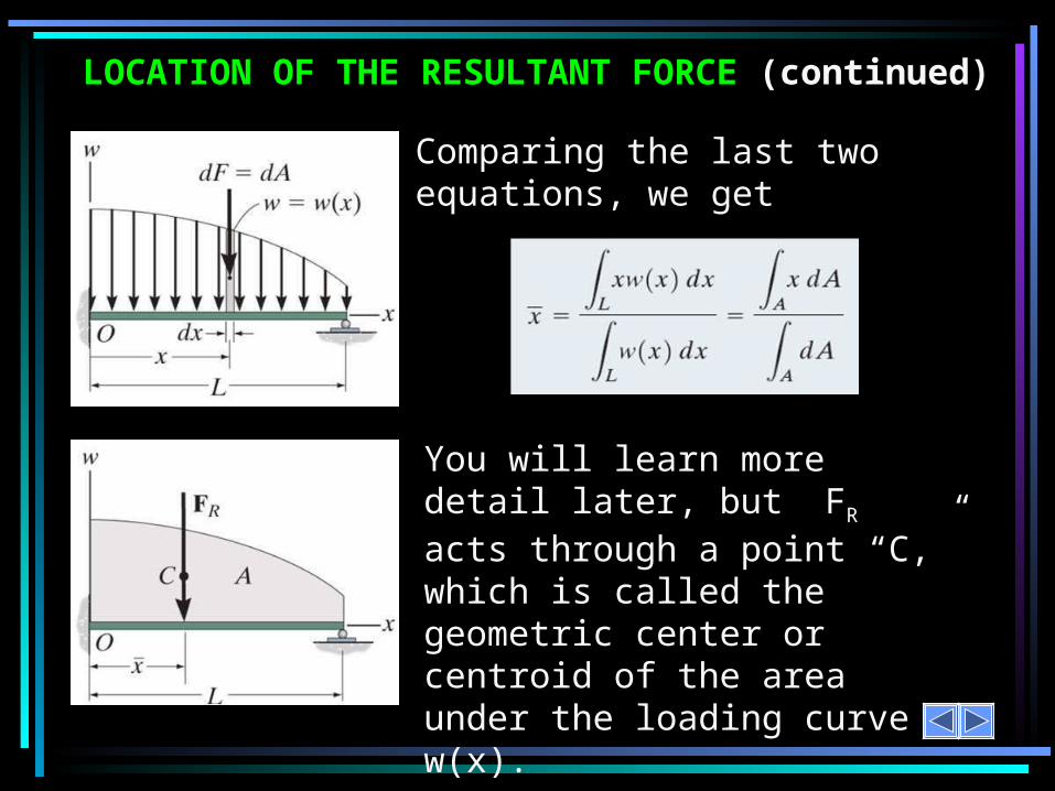
LOCATION OF THE RESULTANT FORCE (continued)
Comparing the last two equations, we get
You will learn more detail later, but FR acts through a point “C,” which is called the geometric center or centroid of the area under the loading curve w(x).

EXAMPLESUntil you learn more about centroids, we will consider only rectangular and triangular loading diagrams whose centroids are well defined and shown on the inside back cover of your textbook.
Look at the inside back cover of your textbook. You should find the rectangle and triangle cases. Finding the area of a rectangle and its centroid is easy!
Note that triangle presents a bit of a challenge but still is pretty straightforward.

EXAMPLES
The rectangular load: FR = 400 10 = 4,000 lb and = 5 ft.x
The triangular loading:FR = (0.5) (600) (6) = 1,800 N and = 6 – (1/3) 6 = 4 m.
Please note that the centroid in a right triangle is at a distance one third the width of the triangle as measured from its base.
x
Now lets complete the calculations to find the concentrated loads (which is a common name for the resultant of the distributed load).
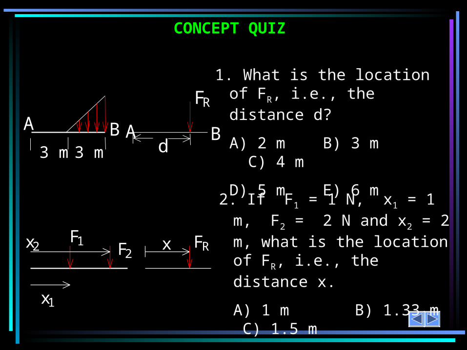
CONCEPT QUIZ
2. If F1 = 1 N, x1 = 1 m, F2 = 2 N and x2 = 2 m, what is the location of FR, i.e., the distance x.
A) 1 m B) 1.33 m C) 1.5 m
D) 1.67 m E) 2 m
FRxF2F1
x1
x2
1. What is the location of FR, i.e., the distance d?
A) 2 m B) 3 m C) 4 m
D) 5 m E) 6 m
FR
BAd
BA
3 m 3 m

GROUP PROBLEM SOLVING
1) The distributed loading can be divided into three parts. (one rectangular loading and two triangular loadings).
2) Find FR and its location for each of these three distributed loads.
3) Determine the overall FR of the three point loadings and its location.
Given: The loading on the beam as shown.
Find: The equivalent force and its location
from point A.
Plan:

GROUP PROBLEM SOLVING (continued)
For the left triangular loading of height 8 kN/m and width 3 m,
FR1 = (0.5) 8 kN/m 3 m = 12 kN
x1 = (2/3)(3m) = 2 m from A
For the top right triangular loading of height 4 kN/m and width 3 m,
FR2 = (0.5) (4 kN/m) (3 m) = 6 kN
and its line of action is at = (1/3)(3m) + 3 = 4 m from Ax2
For the rectangular loading of height 4 kN/m and width 3 m,
FR3 = (4 kN/m) (3 m) = 12 kN
and its line of action is at = (1/2)(3m) + 3 = 4.5 m from Ax3

GROUP PROBLEM SOLVING (continued)
For the combined loading of the three forces, add them.
FR = 12 kN + 6 kN + 12 kN = 30 kN
+ MRA = (2) (12) + 4 (6) + (4.5) 12 = 102 kN • m
Now, (FR x) has to equal MRA = 102 kN • m
So solve for x to find the equivalent force’s location.Hence, x = (102 kN • m) / (30 kN) = 3.4 m from A.

ATTENTION QUIZ
1. FR = ____________
A) 12 N B) 100 N
C) 600 N D) 1200 N
2. x = __________.
A) 3 m B) 4 m
C) 6 m D) 8 m
FR100 N/m
12 m x

Example 1: Draw FBD, show resultant loads and then find the reactions at A and B:
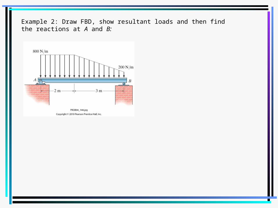
Example 2: Draw FBD, show resultant loads and then find the reactions at A and B:

Example 3: Draw FBD, show resultant loads and then find the reactions at A and B:
Distributed Loads in 3D
• A distributed load in 3D is called a pressure.
• The units of Pressure are:– Lb/in2 (PSI)– Lb/ft2
– N/m2 (Pa)

Distributed Loads in 3D• Consider a 2 ft by
2 ft square plate with a uniform pressure of 15 PSI on it, what is the magnitude and location of the equivalent force created by this pressure?
Related Documents