Lecture 7_Flow in Pipes
Dec 07, 2015
fluid mechanics
Welcome message from author
This document is posted to help you gain knowledge. Please leave a comment to let me know what you think about it! Share it to your friends and learn new things together.
Transcript


2
Objectives
• Have a deeper understanding of laminar and
turbulent flow in pipes and the analysis of fully
developed flow
• Calculate the major and minor losses associated
with pipe flow in piping networks and determine
the pumping power requirements
• Understand various velocity and flow rate
measurement techniques and learn their
advantages and disadvantages
-MFA-
ERT 205 FLUID MECHANICS ENGINEERING [email protected]

3
7–1 ■ INTRODUCTION• Liquid or gas flow through pipes or ducts is commonly used in heating and
cooling applications and fluid distribution networks.
• The fluid in such applications is usually forced to flow by a fan or pump
through a flow section.
• We pay particular attention to friction, which is directly related to the pressure
drop and head loss during flow through pipes and ducts.
• The pressure drop is then used to determine the pumping power requirement.
Circular pipes can
withstand large
pressure differences
between the inside
and the outside
without undergoing
any significant
distortion, but
noncircular pipes
cannot.
-MFA-
ERT 205 FLUID MECHANICS ENGINEERING [email protected]

4
• Theoretical solutions are obtained only for a few simple cases such as
fully developed laminar flow in a circular pipe.
Therefore, we must rely on experimental results and empirical relations for
most fluid flow problems rather than closed-form analytical solutions.
Average velocity Vavg is defined
as the average speed through a
cross section. For fully developed
laminar pipe flow, Vavg is half of
the maximum velocity umax.
Velocity
profile
-MFA-
ERT 205 FLUID MECHANICS ENGINEERING [email protected]

5
7–2 ■ LAMINAR AND
TURBULENT FLOWS
The behavior of
colored fluid
injected into the
flow in laminar and
turbulent flows in a
pipe.
Laminar: Smooth
streamlines and highly
ordered motion.
Turbulent: Velocity
fluctuations and highly
disordered motion.
Transition: The flow
fluctuates between
laminar and turbulent
flows.
Most flows encountered
in practice are turbulent.
Laminar flow is encountered when
highly viscous fluids such as oils flow
in small pipes or narrow passages.
Laminar and
turbulent flow
regimes of candle
smoke. -MFA-
ERT 205 FLUID MECHANICS ENGINEERING [email protected]

6
Reynolds Number
The transition from laminar to turbulent
flow depends on the geometry, surface
roughness, flow velocity, surface
temperature, and type of fluid.
The flow regime depends mainly on the
ratio of inertial forces to viscous forces
(Reynolds number).
The Reynolds number can be
viewed as the ratio of inertial
forces to viscous forces
acting on a fluid element.
At large Reynolds numbers, the inertial
forces, which are proportional to the
fluid density and the square of the fluid
velocity, are large relative to the viscous
forces, and thus the viscous forces
cannot prevent the random and rapid
fluctuations of the fluid (turbulent).
At small or moderate Reynolds
numbers, the viscous forces are large
enough to suppress these fluctuations
and to keep the fluid ―in line‖ (laminar).
-MFA-
ERT 205 FLUID MECHANICS ENGINEERING [email protected]

7
For flow through noncircular
pipes, the Reynolds number
is based on the hydraulic
diameter
For flow in a circular pipe:
The hydraulic diameter Dh = 4Ac/p is
defined such that it reduces to ordinary
diameter for circular tubes.
In the
transitional flow
region of 2300
Re 4,000,
the flow
switches
between
laminar and
turbulent
seemingly
randomly.
Re ≤ 2300 Laminar
2300 ≤ Re ≤ 4000 Transition
Re ≥ 4000 Turbulent
-MFA-
ERT 205 FLUID MECHANICS ENGINEERING [email protected]

Fully Developed Pipe Flow
-There are some major differences between laminar and turbulent fully
developed pipe flows
(a) Laminar
• Can solve exactly
• Flow is steady
• Velocity profile is parabolic
• Pipe roughness not important
• It turns out that Vavg = 1/2Umax and u(r)= 2Vavg(1 - r2/R2)
-MFA-
ERT 205 FLUID MECHANICS ENGINEERING [email protected]

(b) Turbulent
• Cannot solve exactly (too complex)
• Flow is unsteady (3D swirling eddies), but it is steady in the mean
• Mean velocity profile is fuller (shape more like a top-hat profile, with very sharp slope at the wall)
• Pipe roughness is very important
• Vavg 85% of Umax (depends on Re a bit)
• No analytical solution, but there are some good semi-empirical expressions that approximate the velocity profile shape.
Instantaneous
profiles
Fully Developed Pipe Flow
-MFA-
ERT 205 FLUID MECHANICS ENGINEERING [email protected]

10
7-3■ PRESSURE DROP AND HEAD LOSS (MAJOR LOSSES)• A quantity of interest in the analysis of pipe flow is the pressure drop ∆P
since it is directly related to the power requirements of the fan or pump to
maintain flow.
• A pressure drop due to viscous effects represents an irreversible
pressure loss, and it is sometimes called pressure loss PL.
LAMINAR FLOW:
pressure loss for all types
of fully developed
internal flows
dynamic
pressure
Darcy
friction
factor
Circular pipe,
laminarHead
loss
In laminar flow, the friction factor is a function of the Reynolds number only and is
independent of the roughness of the pipe surface.
The head loss represents the additional height that the fluid needs to be raised by
a pump in order to overcome the frictional losses in the pipe.
-MFA-
ERT 205 FLUID MECHANICS ENGINEERING [email protected]
11
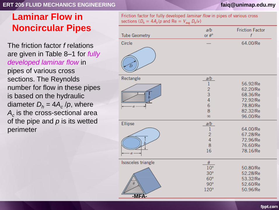
The friction factor f relations
are given in Table 8–1 for fully
developed laminar flow in
pipes of various cross
sections. The Reynolds
number for flow in these pipes
is based on the hydraulic
diameter Dh = 4Ac /p, where
Ac is the cross-sectional area
of the pipe and p is its wetted
perimeter
Laminar Flow in
Noncircular Pipes
-MFA-
ERT 205 FLUID MECHANICS ENGINEERING [email protected]

12
Colebrook equation (for smooth and rough pipes)
f is minimum for
a smooth pipe
and increases
with roughness.
TURBULENT FLOW:
pressure loss for all types
of fully developed
internal flows
Head
loss
• Determine f using (a) Moody Chart or (b) Colebrook Equation
• f in fully developed turbulent pipe flow depends on the Reynolds number and
the relative roughness /D.
-MFA-
ERT 205 FLUID MECHANICS ENGINEERING [email protected]


14
At very large Reynolds numbers, the friction factor
curves on the Moody chart are nearly horizontal, and
thus the friction factors are independent of the
Reynolds number. See Fig. A–12 for a full-page
moody chart.
In calculations, we should
make sure that we use the
actual internal diameter
of the pipe, which may be
different than the nominal
diameter.
-MFA-
ERT 205 FLUID MECHANICS ENGINEERING [email protected]

15
Types of Fluid Flow Problems
1. Determining the pressure drop (or head
loss) when the pipe length and diameter
are given for a specified flow rate (or
velocity)
2. Determining the flow rate when the pipe
length and diameter are given for a
specified pressure drop (or head loss)
3. Determining the pipe diameter when the
pipe length and flow rate are given for a
specified pressure drop (or head loss)
The three types of problems
encountered in pipe flow.
To avoid tedious
iterations in head
loss, flow rate, and
diameter calculations,
these explicit relations
that are accurate to
within 2 percent of the
Moody chart may be
used.-MFA-
ERT 205 FLUID MECHANICS ENGINEERING [email protected]


20
7–4 ■ MINOR LOSSES
The fluid in a typical piping system passes
through various fittings, valves, bends,
elbows, tees, inlets, exits, enlargements,
and contractions in addition to the pipes.
These components interrupt the smooth
flow of the fluid and cause additional
losses because of the flow separation and
mixing they induce.
In a typical system with long pipes, these
losses are minor compared to the total
head loss in the pipes (the major losses)
and are called minor losses.
Minor losses are usually expressed in
terms of the loss coefficient KL.For a constant-diameter section of a pipe with a
minor loss component, the loss coefficient of the
component (such as the gate valve shown) is
determined by measuring the additional
pressure loss it causes and dividing it by the
dynamic pressure in the pipe.Head loss due
to component -MFA-
ERT 205 FLUID MECHANICS ENGINEERING [email protected]
21
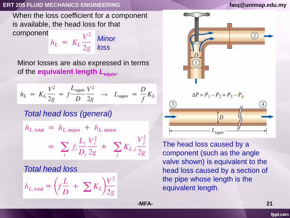
When the loss coefficient for a component
is available, the head loss for that
component isMinor
loss
Minor losses are also expressed in terms
of the equivalent length Lequiv.
The head loss caused by a
component (such as the angle
valve shown) is equivalent to the
head loss caused by a section of
the pipe whose length is the
equivalent length.
Total head loss (general)
Total head loss
-MFA-
ERT 205 FLUID MECHANICS ENGINEERING [email protected]


27
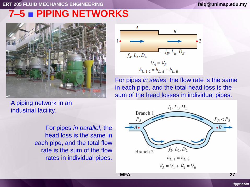
7–5 ■ PIPING NETWORKS
A piping network in an
industrial facility.
For pipes in series, the flow rate is the same
in each pipe, and the total head loss is the
sum of the head losses in individual pipes.
For pipes in parallel, the
head loss is the same in
each pipe, and the total flow
rate is the sum of the flow
rates in individual pipes.
-MFA-
ERT 205 FLUID MECHANICS ENGINEERING [email protected]

28
the steady-flow
energy equation
When a pump
moves a fluid from
one reservoir to
another, the useful
pump head
requirement is
equal to the
elevation difference
between the two
reservoirs plus the
head loss.The efficiency of the pump–motor
combination is the product of the
pump and the motor efficiencies.
Piping Systems with Pumps and Turbines
-MFA-
ERT 205 FLUID MECHANICS ENGINEERING [email protected]


32
7-6 ■ PUMP SELECTION
• Device used to move/transport liquids through pipes & channels.
• Pump increases the mechanical energy, velocity & pressure of the liquid.
• 2 main forms are the positive displacement type & centrifugal pumps.
• Both of which are commonly used for delivery against high pressures &
where nearly constant delivery rates are required.
-MFA-
ERT 205 FLUID MECHANICS ENGINEERING [email protected]

Pump
Positive-displacement
pump
Reciprocating pump
Piston
Plunger
Diaphragm
Rotary pump
Gear
Screw
Lobe
Vane
Centrifugal pump
PUMP SELECTION
-MFA-
ERT 205 FLUID MECHANICS ENGINEERING [email protected]

34
• Force the liquid by changing volume.
• It delivers a pulsating/periodic flow as the cavity volume
opens, traps & squeezes the fluid.
• Advantage: deliver any fluid regardless of viscosity.
• Can operate up to 300 atm (high pressure) but only produces
very low flowrate (100 gal/min).
• At constant rotation speed, it produces nearly constant
flowrate.
POSITIVE DISPLACEMENT PUMP (PDP)
• Flowrate cannot be varied except by changing the
displacement/speed.
• Mechanical efficiency varies from 40-50% for small pumps & 70-
90% for large pumps.
• PDP are classified into two general categories:
- (a) Reciprocating Pump (piston pump, plunger pump, diaphragm
pump)
- (b) Rotary Pump (single rotor, multiple rotors – gear, lobe,
multiple screw)
-MFA-
ERT 205 FLUID MECHANICS ENGINEERING [email protected]

35
(i) Piston pump:
Liquid is drawn through an inlet check valve into
the cylinder by withdrawing of piston & forced
out through discharge check valve on return
stroke.
Piston may be motor driven through reducing
gears.
Max. discharge for piston pumps ~ 50 atm.
(A)-RECIPROCATING PUMPS
-MFA-
ERT 205 FLUID MECHANICS ENGINEERING [email protected]
36
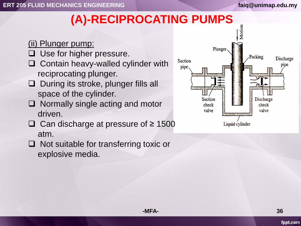
(ii) Plunger pump:
Use for higher pressure.
Contain heavy-walled cylinder with
reciprocating plunger.
During its stroke, plunger fills all
space of the cylinder.
Normally single acting and motor
driven.
Can discharge at pressure of ≥ 1500
atm.
Not suitable for transferring toxic or
explosive media.
(A)-RECIPROCATING PUMPS
-MFA-
ERT 205 FLUID MECHANICS ENGINEERING [email protected]

37
(iii) Diaphragm pump:
o Made of reciprocating flexible diaphragm
metal/plastic/rubber.
o Can handle toxic/corrosive liquids.
o Handle only small to moderate amount of
liquid ~ 100 gal/min.
o Develop pressure up to 100 atm.
(A)-RECIPROCATING PUMPS
-MFA-
ERT 205 FLUID MECHANICS ENGINEERING [email protected]

38
• Contains no check valve.
• Minimize leakage due to close tolerance between moving and
stationary parts.
• Work well with clean and moderately viscous liquids.
• Discharge pressure up to 200 atm or more.
Rotary Lobe Pump Peristaltic Pump
(B)-ROTARY PUMPS
-MFA-
ERT 205 FLUID MECHANICS ENGINEERING [email protected]
39
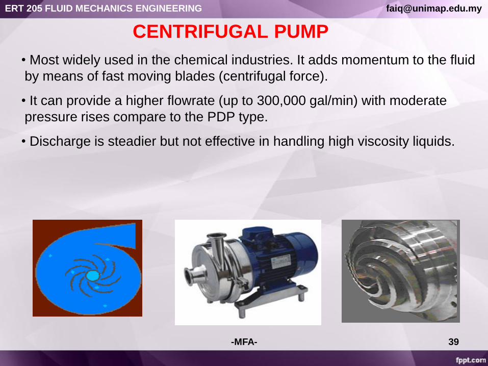
CENTRIFUGAL PUMP
• Most widely used in the chemical industries. It adds momentum to the fluid
by means of fast moving blades (centrifugal force).
• It can provide a higher flowrate (up to 300,000 gal/min) with moderate
pressure rises compare to the PDP type.
• Discharge is steadier but not effective in handling high viscosity liquids.
-MFA-
ERT 205 FLUID MECHANICS ENGINEERING [email protected]

41
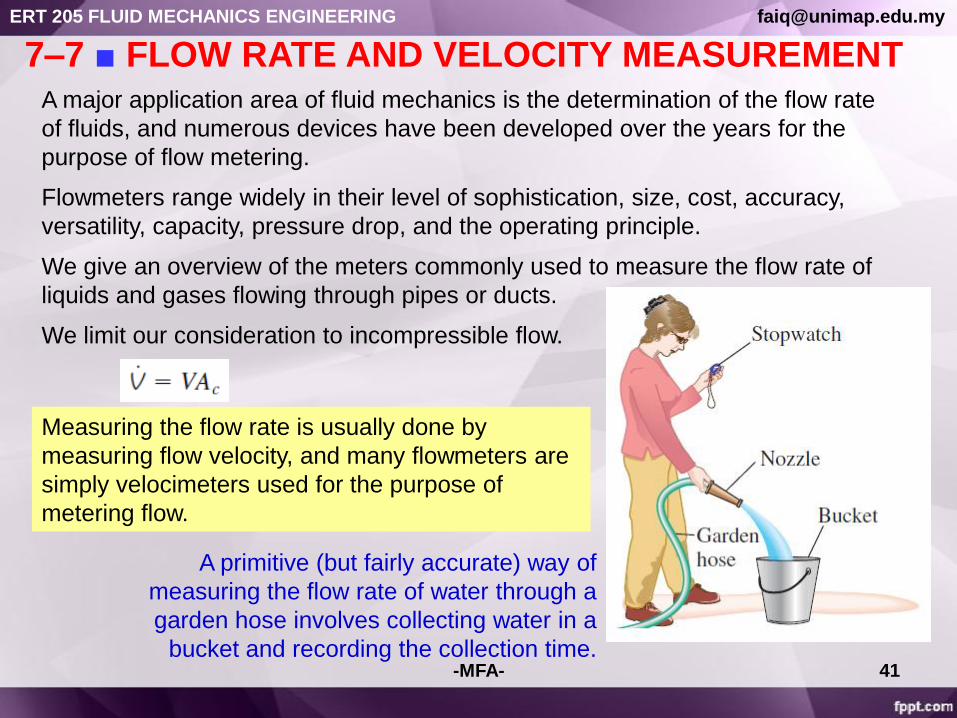
7–7 ■ FLOW RATE AND VELOCITY MEASUREMENTA major application area of fluid mechanics is the determination of the flow rate
of fluids, and numerous devices have been developed over the years for the
purpose of flow metering.
Flowmeters range widely in their level of sophistication, size, cost, accuracy,
versatility, capacity, pressure drop, and the operating principle.
We give an overview of the meters commonly used to measure the flow rate of
liquids and gases flowing through pipes or ducts.
We limit our consideration to incompressible flow.
A primitive (but fairly accurate) way of
measuring the flow rate of water through a
garden hose involves collecting water in a
bucket and recording the collection time.
Measuring the flow rate is usually done by
measuring flow velocity, and many flowmeters are
simply velocimeters used for the purpose of
metering flow.
-MFA-
ERT 205 FLUID MECHANICS ENGINEERING [email protected]

42
Pitot and Pitot-Static ProbesPitot probes (also called Pitot tubes) and Pitot-static probes are widely used for
flow speed measurement.
A Pitot probe is just a tube with a pressure tap at the stagnation point that
measures stagnation pressure, while a Pitot-static probe has both a stagnation
pressure tap and several circumferential static pressure taps and it measures both
stagnation and static pressures
(a) A Pitot probe measures stagnation pressure at the nose of the
probe, while (b) a Pitot-static probe measures both stagnation
pressure and static pressure, from which the flow speed is calculated.-MFA-
ERT 205 FLUID MECHANICS ENGINEERING [email protected]

43
Measuring flow velocity with a
Pitotstatic probe. (A manometer
may be used in place of the
differential pressure transducer.)
Close-up of a Pitot-static probe, showing
the stagnation pressure hole and two of
the five static circumferential pressure
holes.-MFA-
ERT 205 FLUID MECHANICS ENGINEERING [email protected]

44
Obstruction Flowmeters:
Orifice, Venturi, and
Nozzle Meters
Flow through a constriction in a pipe.
Flowmeters based on this principle
are called obstruction flowmeters
and are widely used to measure
flow rates of gases and liquids.
-MFA-
ERT 205 FLUID MECHANICS ENGINEERING [email protected]

45
The losses can be accounted for by incorporating a correction factor called the
discharge coefficient Cd whose value (which is less than 1) is determined
experimentally.
The value of Cd depends on both b and the Reynolds number, and
charts and curve-fit correlations for Cd are available for various types of
obstruction meters.
For flows with high Reynolds numbers (Re > 30,000), the value of
Cd can be taken to be 0.96 for flow nozzles and 0.61 for orifices.
-MFA-
ERT 205 FLUID MECHANICS ENGINEERING [email protected]


50
The total amount of mass or volume of a fluid that
passes through a cross section of a pipe over a
certain period of time is measured by positive
displacement flowmeters.
There are numerous types of displacement
meters, and they are based on continuous filling
and discharging of the measuring chamber. They
operate by trapping a certain amount of incoming
fluid, displacing it to the discharge side of the
meter, and counting the number of such
discharge–recharge cycles to determine the total
amount of fluid displaced.
A nutating disk flowmeter.
A positive
displacement
flowmeter with
double helical
three-lobe
impeller design.
Positive Displacement Flowmeters
-MFA-
ERT 205 FLUID MECHANICS ENGINEERING [email protected]
51
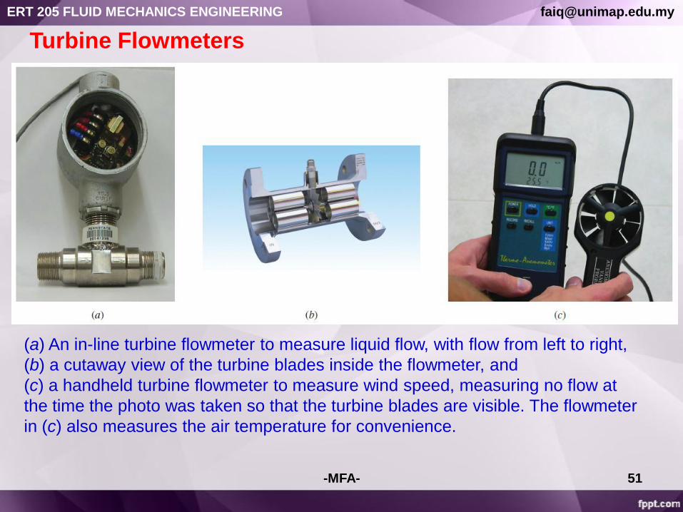
Turbine Flowmeters
(a) An in-line turbine flowmeter to measure liquid flow, with flow from left to right,
(b) a cutaway view of the turbine blades inside the flowmeter, and
(c) a handheld turbine flowmeter to measure wind speed, measuring no flow at
the time the photo was taken so that the turbine blades are visible. The flowmeter
in (c) also measures the air temperature for convenience.
-MFA-
ERT 205 FLUID MECHANICS ENGINEERING [email protected]

52
Paddlewheel Flowmeters
Paddlewheel flowmeter to
measure liquid flow, with
flow from left to right, and a
schematic diagram of
its operation.
Paddlewheel flowmeters are low-cost
alternatives to turbine flowmeters for
flows where very high accuracy is not
required.
The paddlewheel (the rotor and the
blades) is perpendicular to the flow
rather than parallel as was the case
with turbine flowmeters.
-MFA-
ERT 205 FLUID MECHANICS ENGINEERING [email protected]

53
Variable-Area Flowmeters (Rotameters)
A simple, reliable, inexpensive, and easy-to-install
flowmeter with reasonably low pressure drop and
no electrical connections that gives a direct reading
of flow rate for a wide range of liquids and gases is
the variable-area flowmeter, also called a
rotameter or floatmeter.
A variable-area flowmeter consists of a vertical
tapered conical transparent tube made of glass or
plastic with a float inside that is free to move.
As fluid flows through the tapered tube, the float
rises within the tube to a location where the float
weight, drag force, and buoyancy force balance
each other and the net force acting on the float is
zero.
The flow rate is determined by simply matching the
position of the float against the graduated flow
scale outside the tapered transparent tube.
The float itself is typically either a sphere or a
loose-fitting piston-like cylinder.
Two types of variable-area
flowmeters: (a) an ordinary
gravity-based meter and (b) a
spring-opposed meter.
-MFA-
ERT 205 FLUID MECHANICS ENGINEERING [email protected]

54
Ultrasonic Flowmeters
The operation of a transit time ultrasonic
flowmeter equipped with two transducers.
Ultrasonic flowmeters operate using sound waves in the ultrasonic range
( beyond human hearing ability, typically at a frequency of 1 MHz).
Ultrasonic (or acoustic) flowmeters operate by generating sound waves with
a transducer and measuring the propagation of those waves through a
flowing fluid.
There are two basic kinds of ultrasonic flowmeters: transit time and
Doppler-effect (or frequency shift) flowmeters.
L is the distance between the transducers and K is a constant
ERT 205 FLUID MECHANICS ENGINEERING [email protected]
55
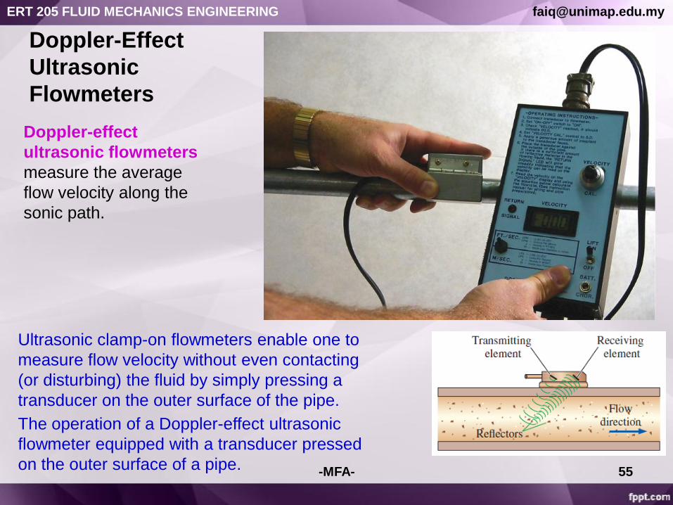
Doppler-Effect
Ultrasonic
Flowmeters
Doppler-effect
ultrasonic flowmeters
measure the average
flow velocity along the
sonic path.
The operation of a Doppler-effect ultrasonic
flowmeter equipped with a transducer pressed
on the outer surface of a pipe.
Ultrasonic clamp-on flowmeters enable one to
measure flow velocity without even contacting
(or disturbing) the fluid by simply pressing a
transducer on the outer surface of the pipe.
-MFA-
ERT 205 FLUID MECHANICS ENGINEERING [email protected]

56
Electromagnetic FlowmetersA full-flow electromagnetic flowmeter is a nonintrusive device that consists of a
magnetic coil that encircles the pipe, and two electrodes drilled into the pipe
along a diameter flush with the inner surface of the pipe so that the electrodes
are in contact with the fluid but do not interfere with the flow and thus do not
cause any head loss.
Insertion electromagnetic flowmeters operate similarly, but the magnetic field is
confined within a flow channel at the tip of a rod inserted into the flow.
(a) Full-flow and (b) insertion
electromagnetic flowmeters,
-MFA-
ERT 205 FLUID MECHANICS ENGINEERING [email protected]
57
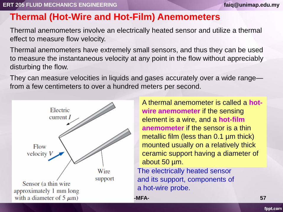
Thermal (Hot-Wire and Hot-Film) Anemometers
The electrically heated sensor
and its support, components of
a hot-wire probe.
Thermal anemometers involve an electrically heated sensor and utilize a thermal
effect to measure flow velocity.
Thermal anemometers have extremely small sensors, and thus they can be used
to measure the instantaneous velocity at any point in the flow without appreciably
disturbing the flow.
They can measure velocities in liquids and gases accurately over a wide range—
from a few centimeters to over a hundred meters per second.
A thermal anemometer is called a hot-
wire anemometer if the sensing
element is a wire, and a hot-film
anemometer if the sensor is a thin
metallic film (less than 0.1 µm thick)
mounted usually on a relatively thick
ceramic support having a diameter of
about 50 µm.
-MFA-
ERT 205 FLUID MECHANICS ENGINEERING [email protected]

58
Laser Doppler Velocimetry
Laser Doppler velocimetry (LDV), also called laser velocimetry (LV) or laser
Doppler anemometry (LDA), is an optical technique to measure flow velocity at
any desired point without disturbing the flow.
Unlike thermal anemometry, LDV involves no probes or wires inserted into the
flow, and thus it is a nonintrusive method.
Like thermal anemometry, it can accurately measure velocity at a very small
volume, and thus it can also be used to study the details of flow at a locality,
including turbulent fluctuations, and it can be traversed through the entire flow
field without intrusion.
A dual-beam LDV system in forward scatter mode.-MFA-
ERT 205 FLUID MECHANICS ENGINEERING [email protected]

REFERENCE
Cengel, Y. A. Cimbala, J. M. ―Fluid
Mechanics: Fundamental and
Applications, First edition in SI units‖
McGraw-Hill. 2006
-MFA- 59
ERT 205 FLUID MECHANICS ENGINEERING [email protected]
Related Documents