4.2 Instrumentation: Pressure, Flow, & Level

Welcome message from author
This document is posted to help you gain knowledge. Please leave a comment to let me know what you think about it! Share it to your friends and learn new things together.
Transcript
4.2 Instrumentation:Pressure, Flow, & Level

Pressure
• Piezoresistive transducers – Resistance bridge – 4 active arm
strain-gauge – Calibration required at temperature – Example: Endevco 8510B – Typical price:
• Pressure capillary extension – Extend capillary from cold
environment up through cryostat to room temperature environment
– Ensure leak-tight – Check mean free path length for low
pressure (vacuum) applications
~ $1K per each

Pressure
• Variable reluctance transducers – Magnetically permeable
stainless steel diaphragm clamped between inductive pick-up coils
– Diaphragm displacement changes induction of both coils
– AC bridge / amplifier circuit converts inductive change to proportional DC output voltage

Cryogenic flow metering techniques
1. Pressure drop devices based on Bernoulli Principle a) Venturi b) Orifice plate c) Pitot tube
2. Friction pressure drop (packed screens) 3. Hot wire anemometers based on h = f(v) 4. Acoustic flow meters based on Doppler effect 5. Turbine flow meters where frequency ~ velocity 6. Optical techniques (Laser Doppler)
Single phase flows
Two phase flows 1. Void fraction measurement (Av/A)
a) Capacitance measurement b) Optical characterization
2. Quality measurement (mv/m)
These techniques are for the most part all used in classical fluid flows.
The unique “cryogenic” features have to do with instrumentation used to detect signal and need for low heat leak.
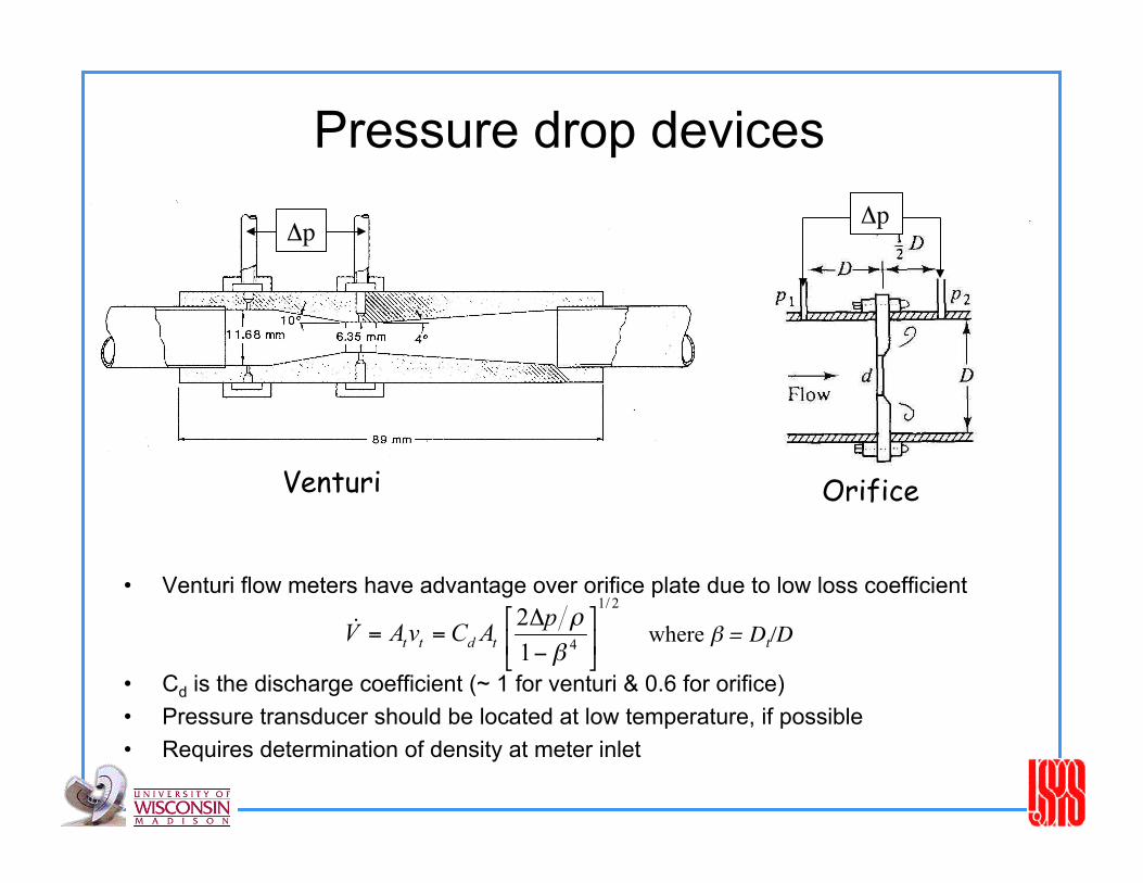
Pressure drop devices
• Venturi flow meters have advantage over orifice plate due to low loss coefficient
• Cd is the discharge coefficient (~ 1 for venturi & 0.6 for orifice) • Pressure transducer should be located at low temperature, if possible • Requires determination of density at meter inlet
Δp
where β = Dt/D
Δp
Venturi Orifice

Packed Screen (AC) Gas flow meters
• Pressure drop is proportional to, and in phase with the mass flow rate
• Other impedance contributions to pressure drop are negligible • Pressure transducers (Endevco, PCB Piezotronics) can be
calibrated for use at cryogenic temperatures

Hot Wire Anemometers

Turbine flow meters
• Rotation speed is proportional to volumetric flow rate
• Linear response function allows a wide range of operation
V
n
.

• Measurement of flow quality (mv/m) in a two phase mixture (liquid + vapor) is difficult. – Vapor velocity and liquid velocity may be different – Flow regime is not known
• Measurement of void fraction (Av/A) is more straightforward – Capacitive meter based on different dielectric constant
– Optical techniques
• Total mass flow rate can be determined in some part of the circuit where the fluid is single phase using a conventional flow meter
Two phase flow measurement
Co-axial capacitor

RF Void Fraction Measurement
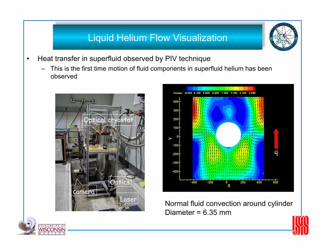
Liquid Helium Flow Visualization
• Heat transfer in superfluid observed by PIV technique – This is the first time motion of fluid components in superfluid helium has been
observed
Laser camera
Optics
Optical cryostat
Normal fluid convection around cylinder Diameter = 6.35 mm

2-phase Helium Flow Visualization

2-phase Helium Flow Visualization

CHF Investigation: modeling • A physical description of void fraction growth or force balance requires
knowledge of bubble size, frequency, spacing and velocity
θ
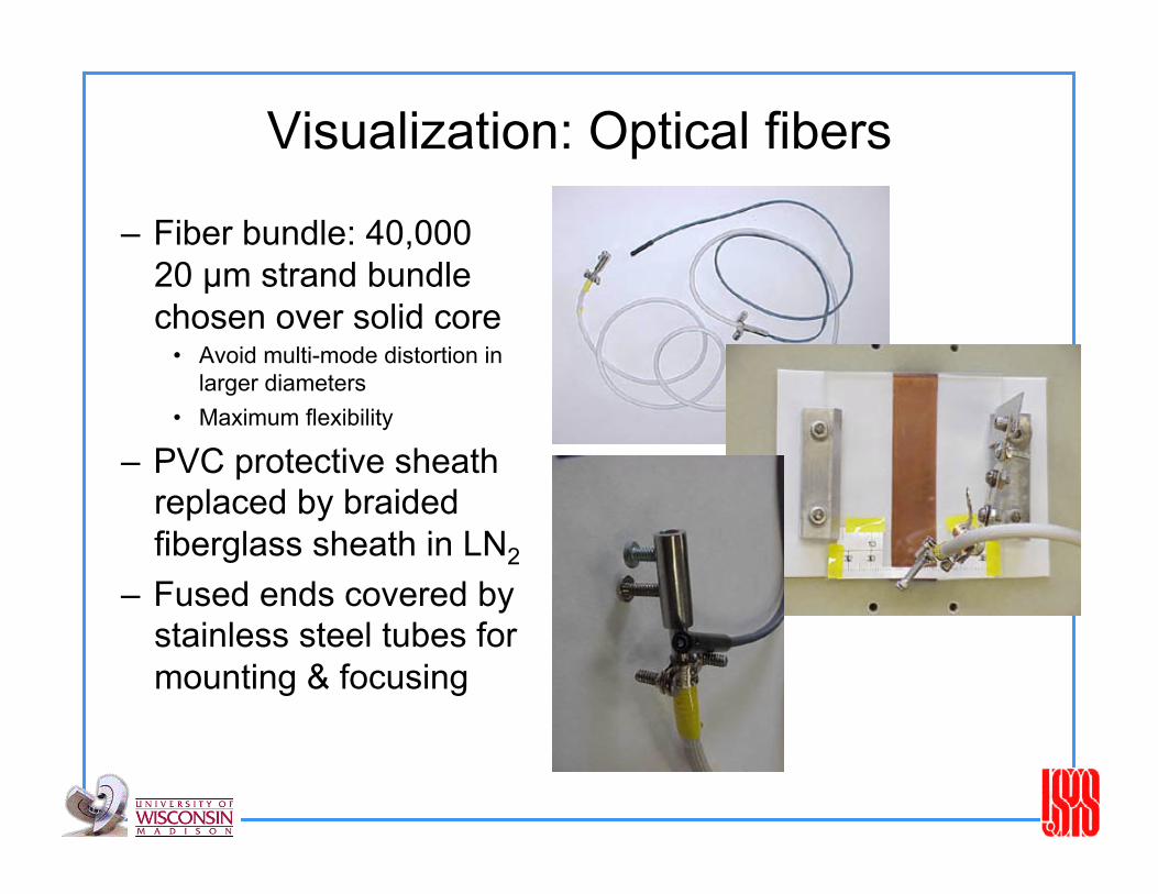
Visualization: Optical fibers
– Fiber bundle: 40,000 20 µm strand bundle chosen over solid core
• Avoid multi-mode distortion in larger diameters
• Maximum flexibility
– PVC protective sheath replaced by braided fiberglass sheath in LN2
– Fused ends covered by stainless steel tubes for mounting & focusing

Visualization: Image Capture
• Phillips CCD camera – Direct fiber to fiber image
transfer. – Camera pixel density
provides ~ 10,000 pixels for 1.9 mm diameter image.
– Minimal illumination required: 4 - LED array provides more illumination than necessary (especially with illumination increase when submerged in LN2).

Visualization: Image Capture • Questar QM100 Images
SLR: • Ektachrome P1600, pushed to 6400. • 1/250 s shutter speed • halogen lamp illumination • horizontal channel - slow bubble motion
Digital camcorder ‘still’ • 1/3000 s shutter speed • halogen lamp illumination • black line spacing in upper right is 1 mm. • vertical channel - ‘fast’ bubble capture

Visualization: Image capture
• CCD Images
• Aperature speed of 1/500 s • Excellent image quality captured on vhs tape - quality reduced upon digitization • Note regular spacing of bubbles (vertical channel flow)

Visualizing Phase Change

Liquid level measurement techniques Continuous level measurement
Superconducting wire level device
Capacitive level measuring systems
Transmission line system
Ultrasonic level measurement
Hydrostatic (head) level measurement
Discrete level measurement
Liquid-vapor detectors (resistive, superconducting)
Acoustic “Dip stick” method
Mass measurement (gauging)
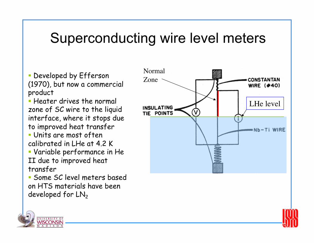
Superconducting wire level meters
LHe level
Normal Zone Developed by Efferson
(1970), but now a commercial product Heater drives the normal zone of SC wire to the liquid interface, where it stops due to improved heat transfer Units are most often calibrated in LHe at 4.2 K Variable performance in He II due to improved heat transfer Some SC level meters based on HTS materials have been developed for LN2
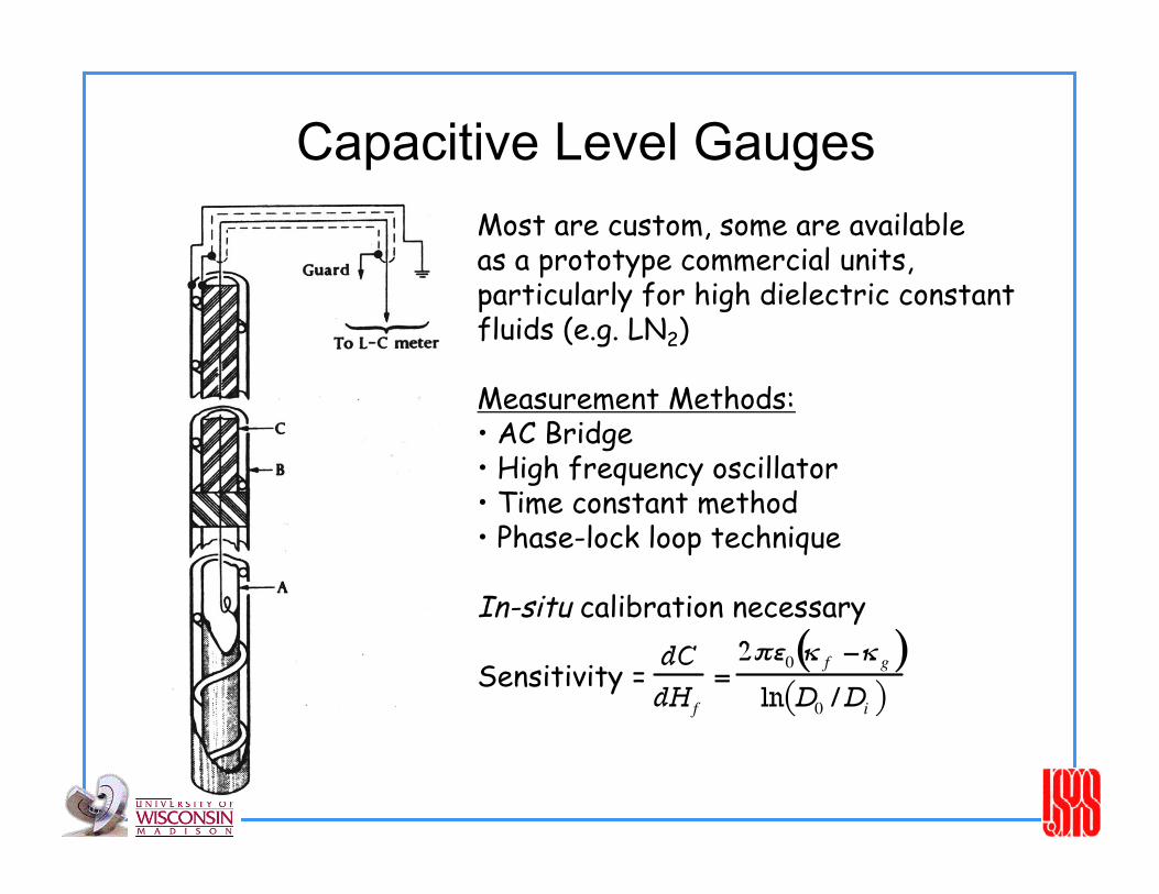
Capacitive Level Gauges Most are custom, some are available as a prototype commercial units, particularly for high dielectric constant fluids (e.g. LN2)
Measurement Methods: • AC Bridge • High frequency oscillator • Time constant method • Phase-lock loop technique
In-situ calibration necessary
Sensitivity =

Differential pressure (head) gauge Q
He H2 Ne N2 O2 Ar ρl 125 70.8 807 1141
ρg 1.33 9.4 4.6 4.47 5.77
Requirements • No liquid in vertical
leg of lower capillary tube
• dp/dL = Δρ g = 1.06 (Pa/mm)helium
• Heat load may be large to keep vapor line dry
16.7
1240 1394

Ultrasonic level measurement
Signal travels at sound speed
≈ 200 m/s for LHe
Level ~ resonant frequency

Discrete level measurement techniques
• Liquid vapor detection (LVD) • Types of devices:
– Superconducting thin films (SnAu)
– Hot wire or film – Semiconductors
• Operating current must be sufficient to self heat the sensor in vapor, but not in liquid
• Sensor must be small to minimize heat generation in liquid

“Dip Stick” level measurement
Acoustic oscillation changes frequency & amplitude when capillary leaves liquid
p p
t

Heat Pulse Mass Gauging Measurement of He II volume (mass) by heat pulse technique
mass = Q/∆h Technique used extensively for space based He II cryostats but also pressurized He II systems for superconducting magnets
From Volz, et al Advances in Cryo. Engn. Vol 35 (1990)

Summary of Level Measurement Techniques
Availability Readout Range of heat Deposition
Continuous Level Measurement Capacitive gauge Prototype Frequency Less than 1mW Superconducting wire Commercial Voltage Tens of mW’s Transmission line Development Frequency On the order of µW
Heat transfer based Development Power/temperature Tens of mW’s Floats Development Visual/voltage Negligible Hydrostatic Development Pressure On the order of mW’s Ulrasonic Development Frequency Less than 1 µW
Liquid-Vapor Detectors SC wire Development Voltage On the order of mW’s Resistive Development Voltage On the order of mW’s Ultrasonic Development Frequency Less than 1 µW
Optical Development Light intensity Less than 1 µW
Mass gauging Internal energy change Development Temperature On the order of 1 Joule
Related Documents