The Design of Highway Alignments Norman W. Garrick Lecture 4 Part 1 Street and Highway Design

Lecture 4 Part 1 Horizontal Curves
Dec 22, 2015
surveying
Welcome message from author
This document is posted to help you gain knowledge. Please leave a comment to let me know what you think about it! Share it to your friends and learn new things together.
Transcript
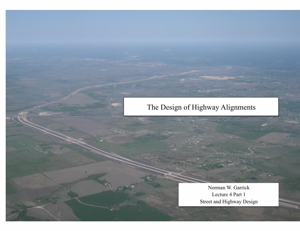
The Design of Highway Alignments
Norman W. Garrick Lecture 4 Part 1
Street and Highway Design

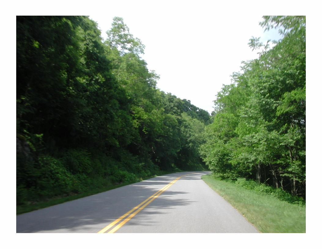
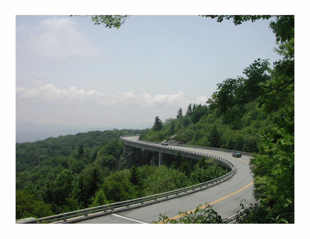
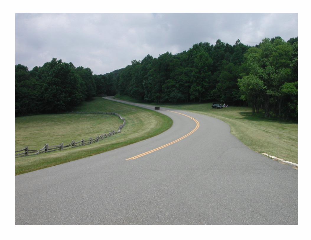
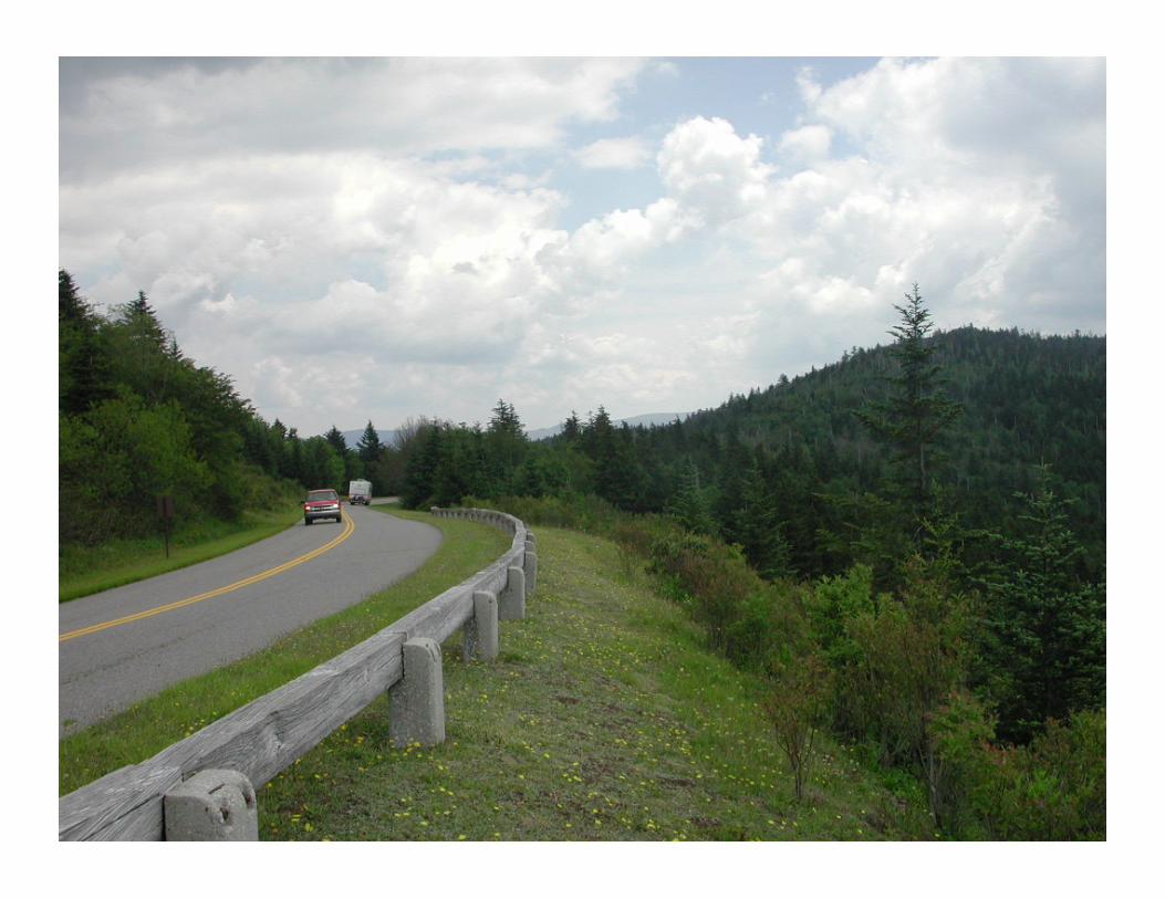
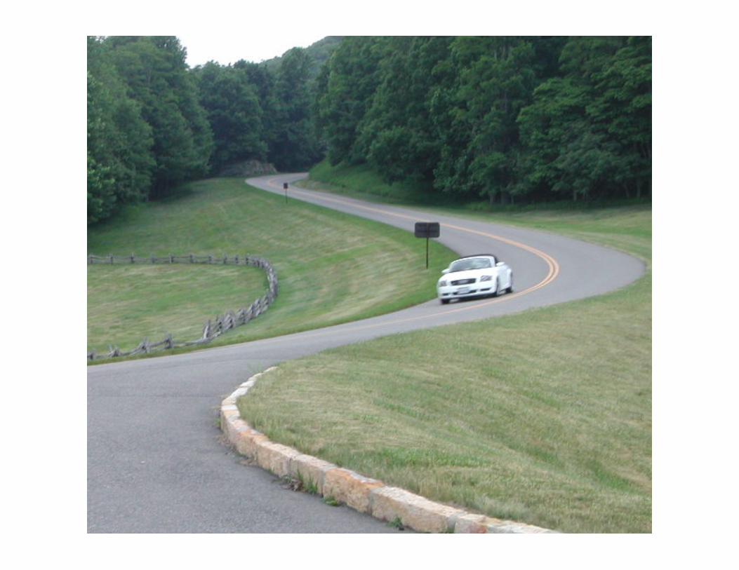
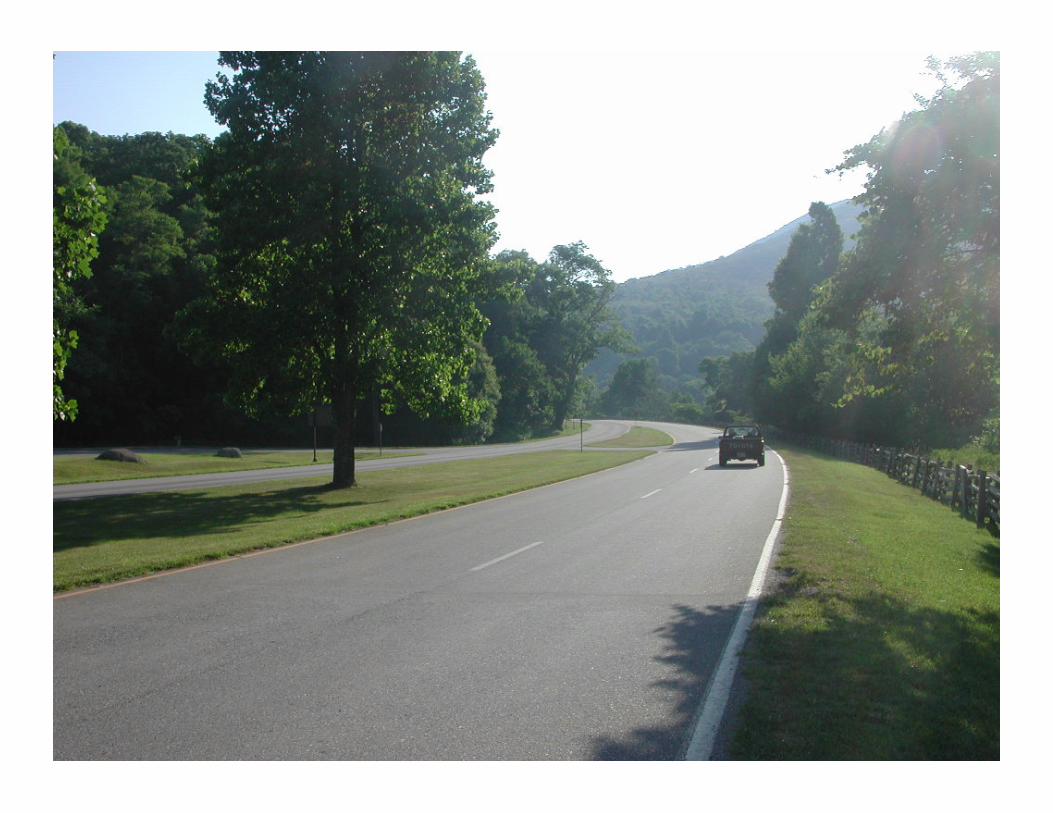
Blue Ridge Parkway

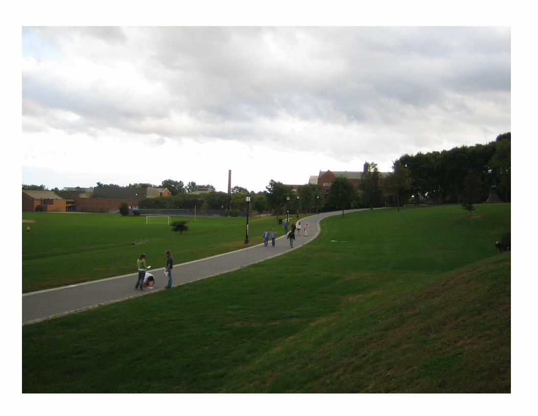
Trinity College Lower Long Walk


Storrs Heights An un-engineered alignment


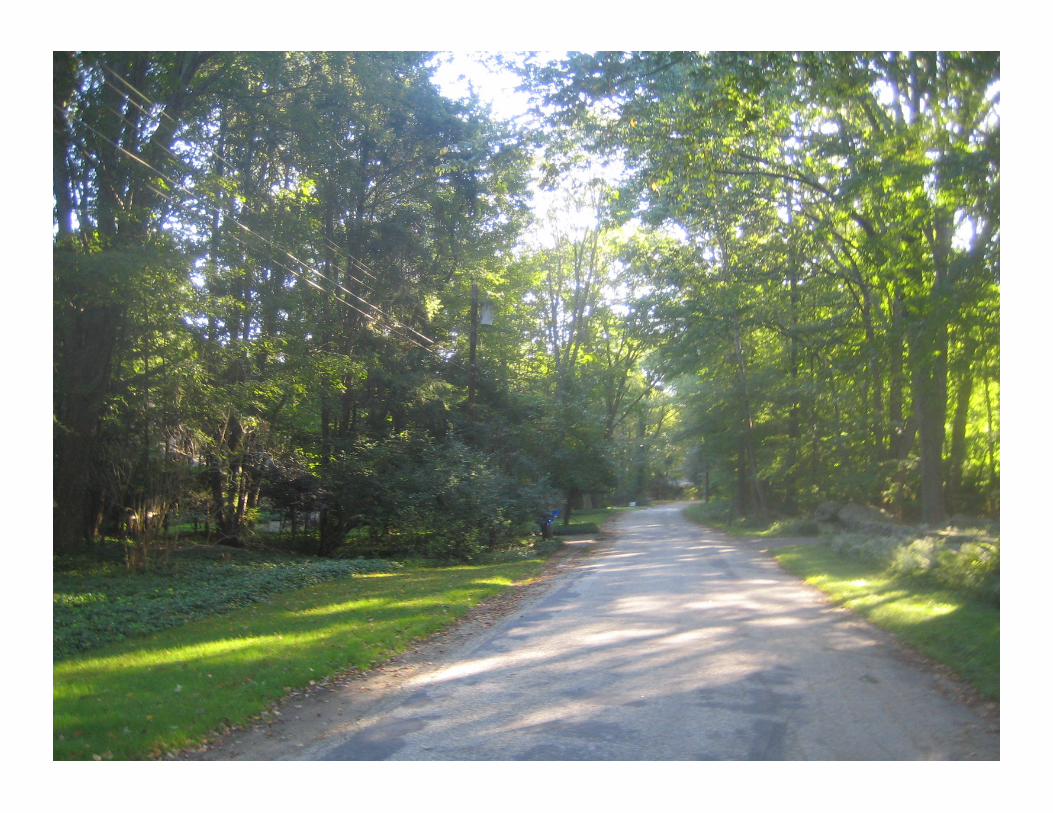
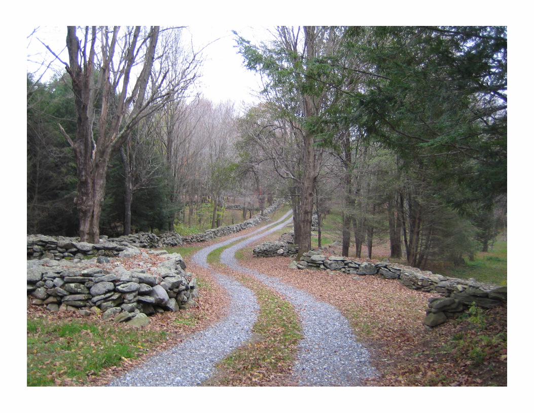
A Driveway in Willington, CT Likely engineered alignment
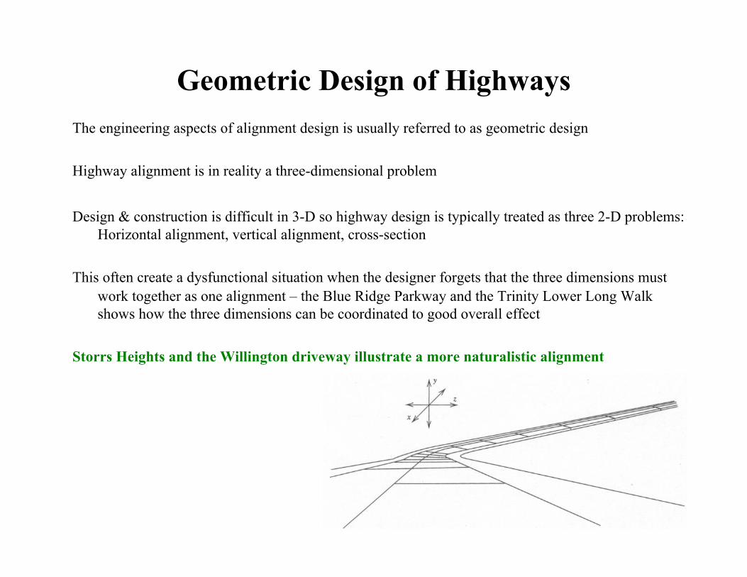
Geometric Design of Highways The engineering aspects of alignment design is usually referred to as geometric design
Highway alignment is in reality a three-dimensional problem
Design & construction is difficult in 3-D so highway design is typically treated as three 2-D problems: Horizontal alignment, vertical alignment, cross-section
This often create a dysfunctional situation when the designer forgets that the three dimensions must work together as one alignment – the Blue Ridge Parkway and the Trinity Lower Long Walk shows how the three dimensions can be coordinated to good overall effect
Storrs Heights and the Willington driveway illustrate a more naturalistic alignment
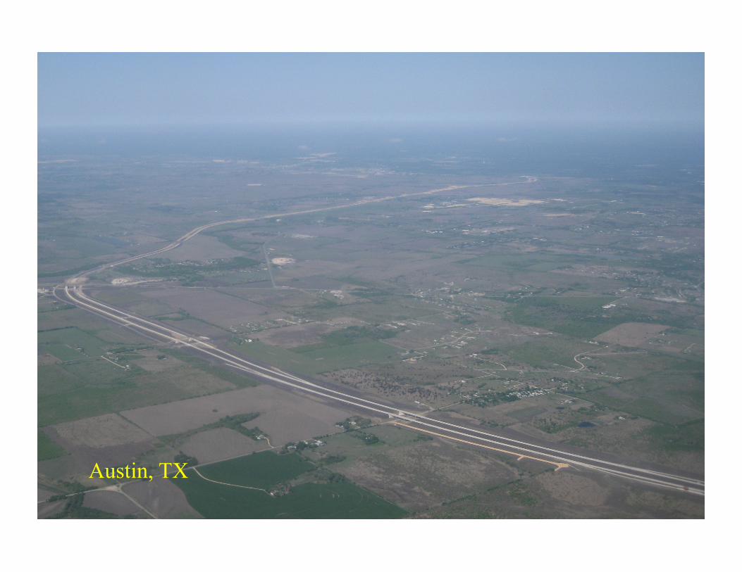
Austin, TX
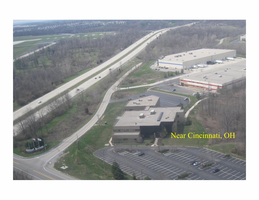
Near Cincinnati, OH

Components of Highway Design
Plan View
Profile View
Horizontal Alignment
Vertical Alignment
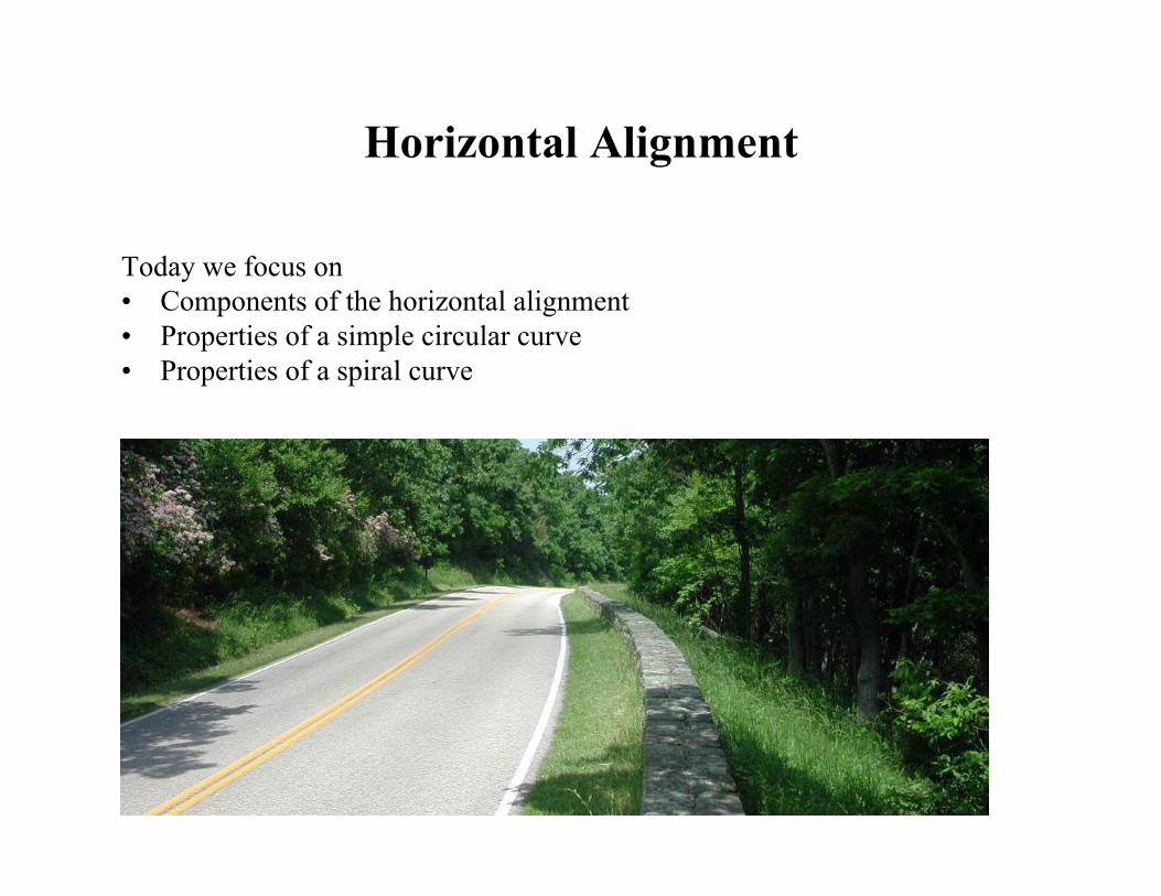
Horizontal Alignment
Today we focus on • Components of the horizontal alignment • Properties of a simple circular curve • Properties of a spiral curve

Horizontal Alignment
Tangents Curves
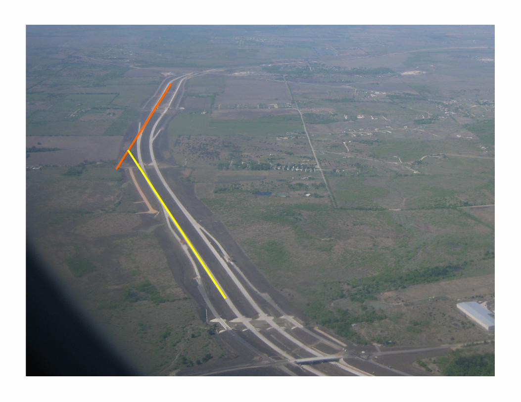
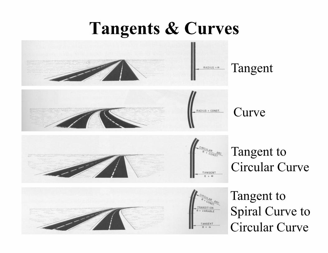
Tangents & Curves
Tangent
Curve
Tangent to Circular Curve
Tangent to Spiral Curve to Circular Curve

Layout of a Simple Horizontal Curve R = Radius of Circular Curve BC = Beginning of Curve (or PC = Point of Curvature) EC = End of Curve (or PT = Point of Tangency) PI = Point of Intersection T = Tangent Length
(T = PI – BC = EC - PI) L = Length of Curvature
(L = EC – BC) M = Middle Ordinate E = External Distance C = Chord Length Δ = Deflection Angle
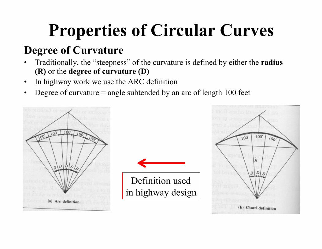
Properties of Circular Curves Degree of Curvature • Traditionally, the “steepness” of the curvature is defined by either the radius
(R) or the degree of curvature (D) • In highway work we use the ARC definition • Degree of curvature = angle subtended by an arc of length 100 feet
Definition used in highway design
Degree of Curvature Equation for D
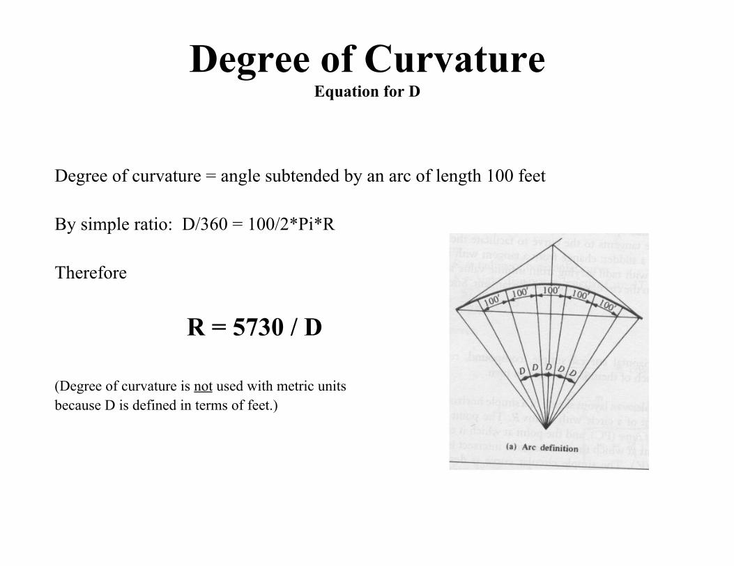
Degree of curvature = angle subtended by an arc of length 100 feet
By simple ratio: D/360 = 100/2*Pi*R
Therefore
R = 5730 / D
(Degree of curvature is not used with metric units because D is defined in terms of feet.)

Length of Curve
By simple ratio: D/ Δ = ?
D/ Δ = 100/L
L = 100 Δ / D
Therefore
L = 100 Δ / D Or (from R = 5730 / D, substitute for D = 5730/R)
L = Δ R / 57.30
(note: D is not Δ )
Properties of Circular Curves
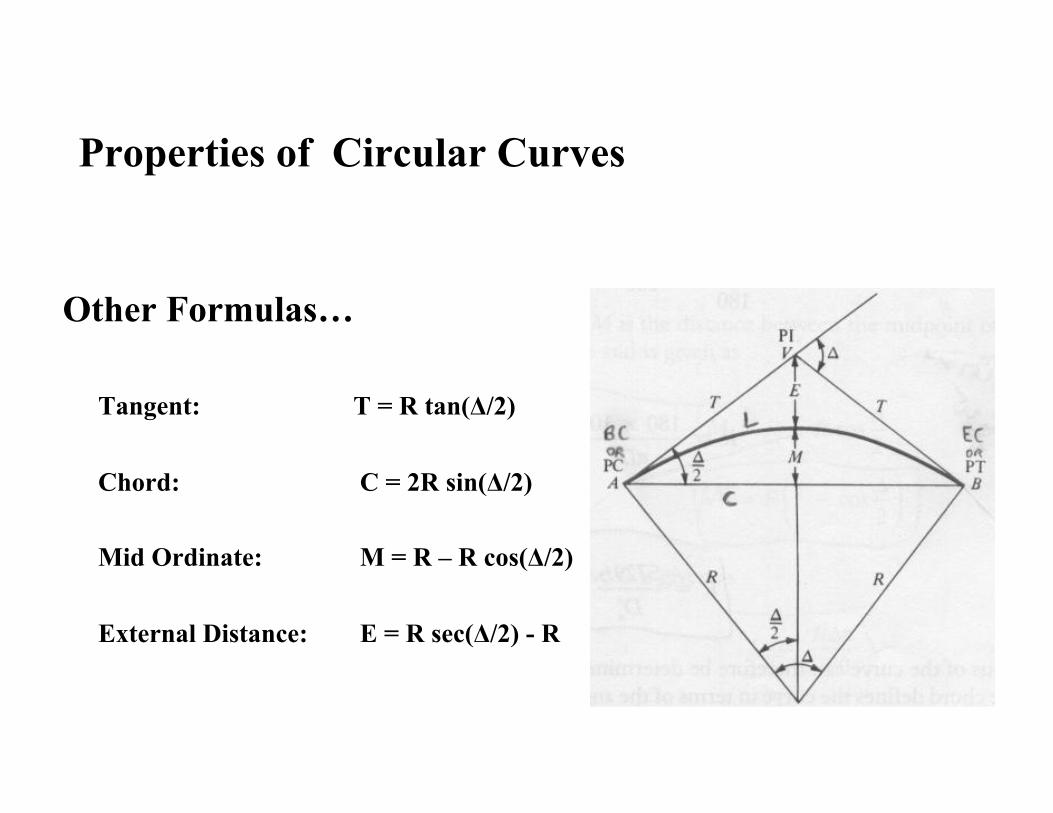
Other Formulas…
Tangent: T = R tan(Δ/2)
Chord: C = 2R sin(Δ/2)
Mid Ordinate: M = R – R cos(Δ/2)
External Distance: E = R sec(Δ/2) - R
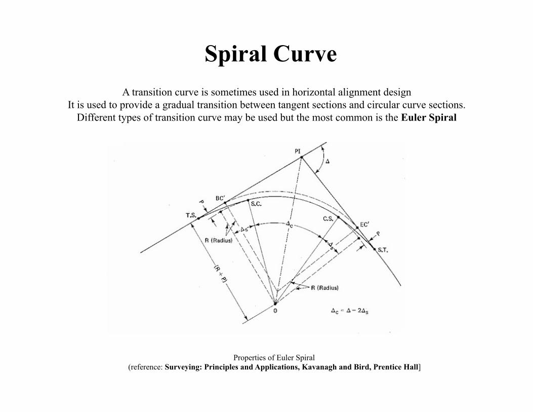
Spiral Curve A transition curve is sometimes used in horizontal alignment design
It is used to provide a gradual transition between tangent sections and circular curve sections. Different types of transition curve may be used but the most common is the Euler Spiral
Properties of Euler Spiral (reference: Surveying: Principles and Applications, Kavanagh and Bird, Prentice Hall]
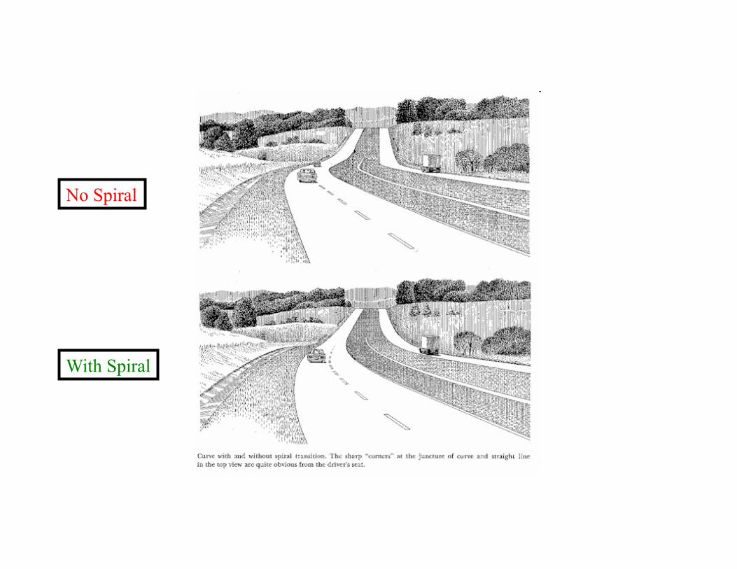
No Spiral
With Spiral

Degree of Curvature of a spiral at any point is proportional to its length at that point
The spiral curve is defined by ‘k’ the rate of increase in degree of curvature per station (100 ft)
In other words,
k = 100 D/ Ls
Characteristics of Euler Spiral
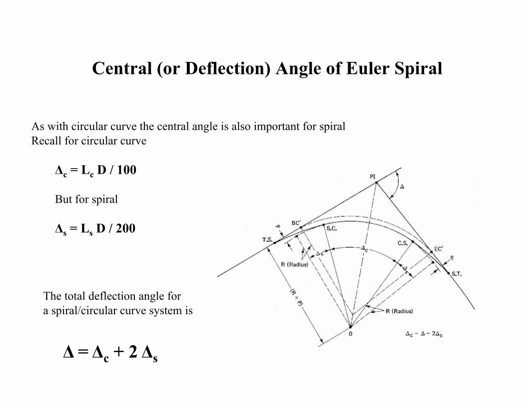
As with circular curve the central angle is also important for spiral Recall for circular curve
Δc = Lc D / 100
But for spiral
Δs = Ls D / 200
Central (or Deflection) Angle of Euler Spiral
The total deflection angle for a spiral/circular curve system is
Δ = Δc + 2 Δs
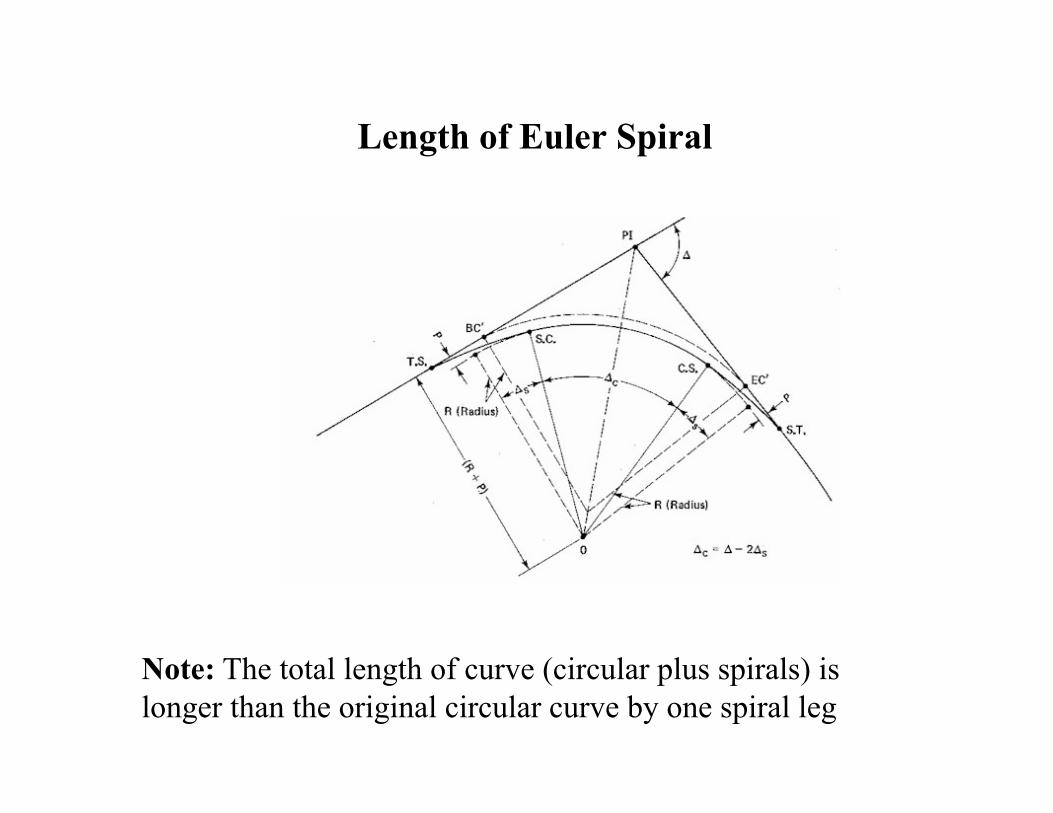
Length of Euler Spiral
Note: The total length of curve (circular plus spirals) is longer than the original circular curve by one spiral leg
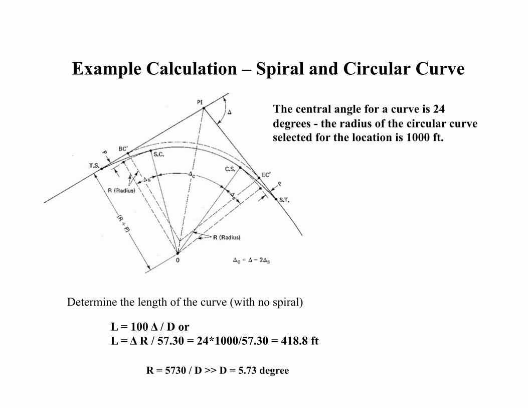
Example Calculation – Spiral and Circular Curve
The central angle for a curve is 24 degrees - the radius of the circular curve selected for the location is 1000 ft.
Determine the length of the curve (with no spiral)
L = 100 Δ / D or L = Δ R / 57.30 = 24*1000/57.30 = 418.8 ft
R = 5730 / D >> D = 5.73 degree

Example Calculation – Spiral and Circular Curve
The central angle for a curve is 24 degrees - the radius of the circular curve selected for the location is 1000 ft
If a spiral with central angle of 4 degrees is selected for use, determine the
i) k for the spiral, ii) ii) length of each spiral leg, iii) iii) total length of curve
Δs = 4 degrees
Δs = Ls D / 200 >> 4 = Ls * 5.73/200 >> Ls = 139.6 ft
k = 100 D/ Ls = 100 * 5.73/ 139.76 = 4.1 degree/100 feet
Total Length of curve = length with no spiral + Ls = 418.8+139.76 = 558.4 feet
Related Documents