MODULE -1 TRANSFORMER TESTING TRAINING SESSION ON TRAINING SESSION ON QUALITY & TESTING OF QUALITY & TESTING OF TRANSFORMER TRANSFORMER PRESENTED BY PRESENTED BY RAZA AFTAB RAZA AFTAB SUPPORTED BY SUPPORTED BY JAHANZEB AHMED & JAHANZEB AHMED & MUHAMMAD SHAFIQUE MUHAMMAD SHAFIQUE

Lecture # 2, Measurment of Impedance Voltage & Load Loss
Dec 25, 2015
Testing
Welcome message from author
This document is posted to help you gain knowledge. Please leave a comment to let me know what you think about it! Share it to your friends and learn new things together.
Transcript

MODULE -1 TRANSFORMER TESTING
TRAINING SESSION ON TRAINING SESSION ON QUALITY & TESTING OF QUALITY & TESTING OF
TRANSFORMERTRANSFORMERPRESENTED BY PRESENTED BY
RAZA AFTABRAZA AFTAB
SUPPORTED BY SUPPORTED BY JAHANZEB AHMED & JAHANZEB AHMED &
MUHAMMAD SHAFIQUEMUHAMMAD SHAFIQUE

MODULE -1 TRANSFORMER TESTING
TRAINING SESSION ON QUALITY & TESTING TRAINING SESSION ON QUALITY & TESTING OF TRANSFORMEROF TRANSFORMER
CONTENTSCONTENTS
1. Measurement of No-Load Loss & Acoustic Sound Level √
2. Measurement of Impedance Voltage & Load Loss
3. Separate Source & Induce Over-voltage withstand test (with measurement of Partial Discharges)
4. Lightning impulse over-voltage withstand test
5. Heat run (temperature rise test)
6. Measurement of zero-sequence impedance
7. Measurement of voltage & current harmonics
8. Tests on OLTC & Insulating Oil
MODULE -1 TRANSFORMER TESTING
TRAINING SESSION ON QUALITY & TESTING TRAINING SESSION ON QUALITY & TESTING OF TRANSFORMEROF TRANSFORMER
Measurement of Load Loss & Impedance voltage
DEFINITIONIt is the absorbed active power at rated frequency and reference temperature associated with a pair of windings when rated current is flowing through the line terminals of one of the windings and the terminals of the other winding are short-circuited.
Load losses has an importance from the economical point of view. .
Load loss = ohmic loss of windings and internal connections + stray losses (eddy current losses due to leakage field)
MODULE -1 TRANSFORMER TESTING
TRAINING SESSION ON QUALITY & TESTING TRAINING SESSION ON QUALITY & TESTING OF TRANSFORMEROF TRANSFORMER
Measurement of Load Loss & Impedance voltage
PURPOSEThe purpose of this test is to determine the power losses (I2R) in the windings for the capitalization of losses and for determining the required loading during the temperature rise test. The test is performed at principal and extreme tap positions if the taps provided are > + 5%.
IEC declare it as a routine test
AFFECTED BYTemperature, I2, frequency, instrument accuracy at low power factorCLASS
MODULE -1 TRANSFORMER TESTING
TRAINING SESSION ON QUALITY & TESTING TRAINING SESSION ON QUALITY & TESTING OF TRANSFORMEROF TRANSFORMER
Measurement of Load Loss & Impedance voltage
STANDARDS
IEC 60076-1, Clause 10.1 & 10.4 and IEC 60076-8, Clause 10TOLERANCE
S PL: +15% of guaranteed value provided total loss does
not exceed guaranteed value by more than 10%.
MODULE -1 TRANSFORMER TESTING
TRAINING SESSION ON QUALITY & TESTING TRAINING SESSION ON QUALITY & TESTING OF TRANSFORMEROF TRANSFORMER
Measurement of Load Loss & Impedance voltage
EQUIPMENTS/INSTRUMENTS1. Motor-Generator Set2. Adapter Transformer3. Power Analyzer4. Precision Current Transformer5. Precision Potential Transformer6. Compensation Capacitors

MODULE -1 TRANSFORMER TESTING
TRAINING SESSION ON QUALITY & TESTING TRAINING SESSION ON QUALITY & TESTING OF TRANSFORMEROF TRANSFORMER
Measurement of Load Loss & Impedance voltage
MEASURING CIRCUIT
MODULE -1 TRANSFORMER TESTING
TRAINING SESSION ON QUALITY & TESTING TRAINING SESSION ON QUALITY & TESTING OF TRANSFORMEROF TRANSFORMER
Measurement of Load Loss & Impedance voltage
PROCEDURERated current is generally applied to the HV windings with the LV short circuited. The test is usually carried out at the principal and extreme taps. Test current should be close to the value of rated current as much as possible and the voltage waveform should be in sinusoidal form with rated frequency. If rated current is not available, then current greater than 50% is preferable. The voltage, current and load losses for each phase should be measured during the test. In case that the generator could not supply the system, the reactive power is encountered by using the capacitor banks.

MODULE -1 TRANSFORMER TESTING
TRAINING SESSION ON QUALITY & TESTING TRAINING SESSION ON QUALITY & TESTING OF TRANSFORMEROF TRANSFORMER
Measurement of Load Loss & Impedance voltage
PROCEDURE - continued…..The readings have to be taken as quickly as possible to prevent the temperature changes in the windings and the applied current should be sustained 25% - 100% of rated current. This increases the accuracy of the reading.
Now according to IEC the measured value of the losses shall be referred to a winding temperature 75ºC. The transformer is at ambient (tm) temperature when the measurements are carried out, the loss value are corrected to the reference temperature (75ºC) according to the standards as follows:
MODULE -1 TRANSFORMER TESTING
TRAINING SESSION ON QUALITY & TESTING TRAINING SESSION ON QUALITY & TESTING OF TRANSFORMEROF TRANSFORMER
Measurement of Load Loss & Impedance voltage
PROCEDURE - continued…..The d.c. losses Pac at the measuring temperature tm are
calculated using the resistance values RHV and RLV obtained in the resistance measurement: RHV and RLV between the line terminals.
DC losses at tm measuring temperature Pdc = 1.5(I2.RHV + I2.RLV)
Additional losses at tm measuring temperature Pac = Pkm - Pdc

MODULE -1 TRANSFORMER TESTING
TRAINING SESSION ON QUALITY & TESTING TRAINING SESSION ON QUALITY & TESTING OF TRANSFORMEROF TRANSFORMER
Measurement of Load Loss & Impedance voltage
PROCEDURE - continued…..If the measuring current is different than the rated current, then the load losses are calculated referring the rated current as follows:
Pk = Pkm. (IN/Im)2 where: Im = Measured currentPkm = Measured load lossesPk = Load losses at rated
current
MODULE -1 TRANSFORMER TESTING
TRAINING SESSION ON QUALITY & TESTING TRAINING SESSION ON QUALITY & TESTING OF TRANSFORMEROF TRANSFORMER
Measurement of Load Loss & Impedance voltage
PROCEDURE - continued…..The load losses at reference temperature:
Pk = Pdc. t1 + 75ºC + Pac. t1 + 75ºC where: Im = Measured current ts + tm ts + tm Pkm = Measured load losses
Pk = Load losses at rated It1 = 235ºC for Copper = 225ºC for Aluminum

MODULE -1 TRANSFORMER TESTING
TRAINING SESSION ON QUALITY & TESTING TRAINING SESSION ON QUALITY & TESTING OF TRANSFORMEROF TRANSFORMER
Measurement of Load Loss & Impedance voltage
TEST RESULTS
Following items are recorded in the test report:
1. Impedance voltage2. Measured current3. Load losses at the measured current4. Ambient temperature5. Load losses at rated current & reference temperature6. Percentage impedance at rated current & reference temperature

MODULE -1 TRANSFORMER TESTING
TRAINING SESSION ON QUALITY & TESTING TRAINING SESSION ON QUALITY & TESTING OF TRANSFORMEROF TRANSFORMER
Measurement of Load Loss & Impedance voltage
PRECAUTIONS
1. CT secondary should be shorted.2. Condenser bushing taps to be earthed.3. Readings should be taken quickly to keep the temperature almost constant.4. Voltage should be measured at the terminals to avoid addition of cable losses.5. Applied current should be controlled for gradual increase from zero to prevent inrush current.
MODULE -1 TRANSFORMER TESTING
TRAINING SESSION ON QUALITY & TESTING TRAINING SESSION ON QUALITY & TESTING OF TRANSFORMEROF TRANSFORMER
Measurement of Load Loss & Impedance voltage
DEFINITIONIt is the equivalent series impedance Z = R + jX in (a.c.) ohms at rated frequency and reference temperature, across the terminals of one winding of a pair, when the terminals of the other winding are short circuited.
For a 3-phase transformer the impedance is expressed as phase impedance, in a transformer having a tapped winding, the short circuit impedance is referred to a particular tapping unless other specified, the principal tapping applies.
Short circuit impedance voltage is an important parameter for the parallel operation of the transformers and fault calculations.

MODULE -1 TRANSFORMER TESTING
TRAINING SESSION ON QUALITY & TESTING TRAINING SESSION ON QUALITY & TESTING OF TRANSFORMEROF TRANSFORMER
Measurement of Load Loss & Impedance voltage
PURPOSEThe purpose of determining the short circuit impedance voltage is the parallel operation of the transformer and fault calculations. The test is performed at principal and extreme tap positions if the taps provided are > + 5%.
IEC declare it as a routine test
AFFECTED BYTemperature, I2, frequency, instrument accuracy at low power factorCLASS

MODULE -1 TRANSFORMER TESTING
TRAINING SESSION ON QUALITY & TESTING TRAINING SESSION ON QUALITY & TESTING OF TRANSFORMEROF TRANSFORMER
Measurement of Load Loss & Impedance voltage
STANDARDS
IEC 60076-1, Clause 10.1 & 10.4 and IEC 60076-8, Clause 10TOLERANCE
S For a 2-winding or specified 1st winding pair of multi-winding :- principle tapping ± 7.5% (if Z ≥ 10%), ± 10% (if Z < 10%); any other tapping: ± 10% (if Z ≥ 10%), ± 15% (if Z < 10%). Auto connected winding pair or specified 2nd winding pair of multi-winding :- principal tapping: ± 10% of declared value; any other tapping of the pair: ± 15%. Further winding pairs: to be agreed but ≥ ± 15% of declared value.
MODULE -1 TRANSFORMER TESTING
TRAINING SESSION ON QUALITY & TESTING TRAINING SESSION ON QUALITY & TESTING OF TRANSFORMEROF TRANSFORMER
Measurement of Load Loss & Impedance voltage
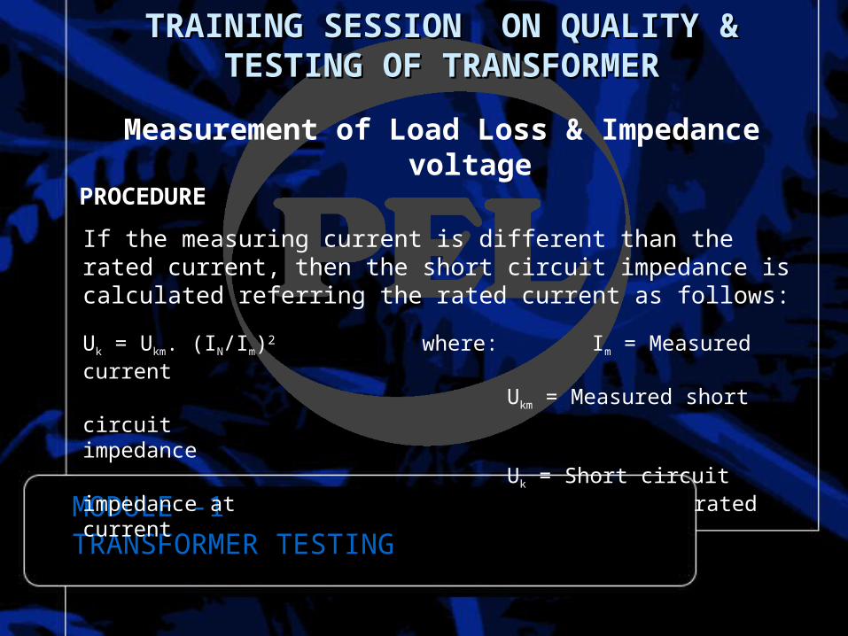
PROCEDURE
If the measuring current is different than the rated current, then the short circuit impedance is calculated referring the rated current as follows:
Uk = Ukm. (IN/Im)2 where: Im = Measured currentUkm = Measured short circuit impedanceUk = Short circuit impedance at rated current

MODULE -1 TRANSFORMER TESTING
TRAINING SESSION ON QUALITY & TESTING TRAINING SESSION ON QUALITY & TESTING OF TRANSFORMEROF TRANSFORMER
Measurement of Load Loss & Impedance voltage
PROCEDURE
The short circuit impedance at measuring temperature tm can be calculated as follows:
Ukm = 100. (Ukm/Un) %
URM = 100. (Pkm/SN) % Ohmic component
Ukm = √U2km – U2
RM % Inductive component
MODULE -1 TRANSFORMER TESTING
TRAINING SESSION ON QUALITY & TESTING TRAINING SESSION ON QUALITY & TESTING OF TRANSFORMEROF TRANSFORMER
Measurement of Load Loss & Impedance voltage
PROCEDURE
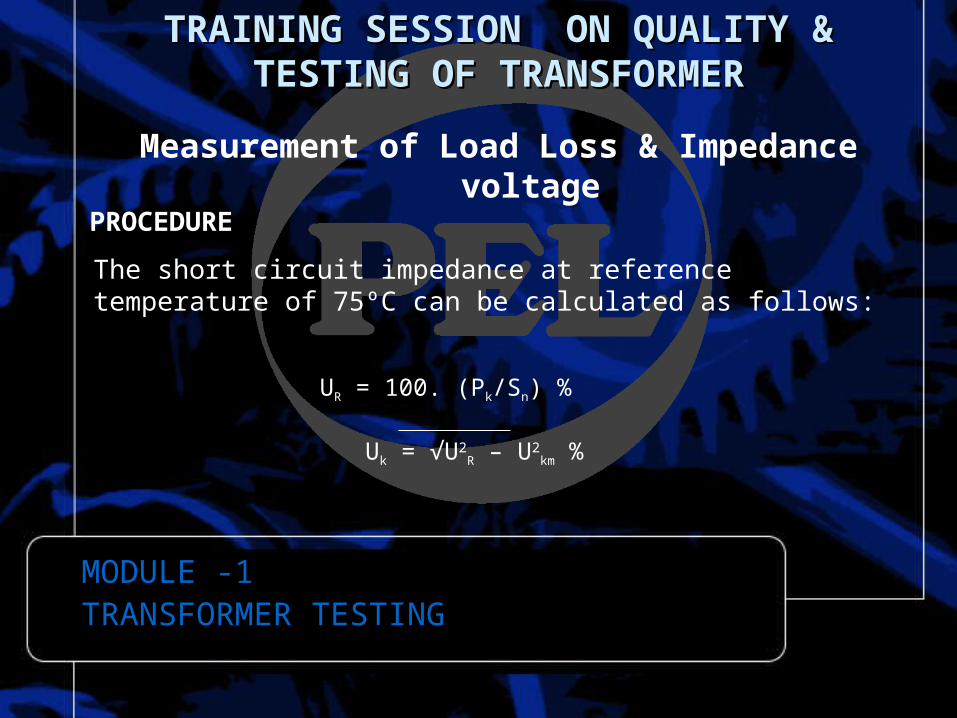
The short circuit impedance at reference temperature of 75ºC can be calculated as follows:
UR = 100. (Pk/Sn) %
Uk = √U2R – U2
km %

THANK YOU
Related Documents