1 Lecture 2 Introduction to VHDL Aim of HDLs (documentation/verification/synthesis) Four main parts of VHDL description Library declarations Built-in type: bit The most popular type: std_logic Entity (definition of interface) Ports (the most popular: in, out, inout) Parameters (generics) Architecture (definition of functionality) Declarations (constants, signals, types, functions, components) Body (concurrent statements as pieces of hardware) Configuration Two types of digital elements (combinational and sequential) Basic concurrent statements Concurrent assignment Component instantiation Simulations Testbench Delayed assignments Inertial vs transport assignment Authors: Rafał Kiełbik, Grzegorz Jabłoński

Welcome message from author
This document is posted to help you gain knowledge. Please leave a comment to let me know what you think about it! Share it to your friends and learn new things together.
Transcript
1
Lecture 2
Introduction to VHDLAim of HDLs (documentation/verification/synthesis)Four main parts of VHDL description
Library declarationsBuilt-in type: bitThe most popular type: std_logic
Entity (definition of interface)Ports (the most popular: in, out, inout)Parameters (generics)
Architecture (definition of functionality)Declarations (constants, signals, types, functions, components)Body (concurrent statements as pieces of hardware)
ConfigurationTwo types of digital elements (combinational and sequential)Basic concurrent statements
Concurrent assignmentComponent instantiation
SimulationsTestbenchDelayed assignmentsInertial vs transport assignment
Authors: Rafał Kiełbik, Grzegorz Jabłoński

2
Aim of HDLs (documentation/verification/synthesis)

3
About VHDL● VHDL is a hardware description language
– Describes behaviour of electronic system
– Based on this description, the system will be implemented
● Very High Speed Integrated Circuits Hardware Description Language
– Created by order of USA Department of Defense
● VHDL 87● VHDL 93● VHDL 2008
● The first HDL to become the IEEE standard
– IEEE 1076
– IEEE 1164 describes multivalue logic
● Originally developed to document the behavior of the ASICs
● Later used also for simulations
● Today VHDL can be used for synthesis, but not all VHDL constructs are synthesizable
VHDL
SynthesizableVHDL

4
Four main parts of VHDL description
5
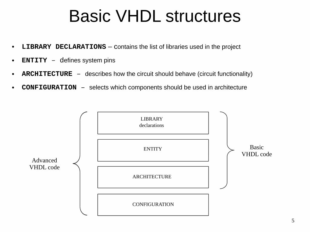
Basic VHDL structures
● LIBRARY DECLARATIONS – contains the list of libraries used in the project
● ENTITY – defines system pins
● ARCHITECTURE – describes how the circuit should behave (circuit functionality)
● CONFIGURATION – selects which components should be used in architecture
LIBRARYdeclarations
ENTITY
ARCHITECTURE
BasicVHDL code
CONFIGURATION
AdvancedVHDL code

6
Library declaration
LIBRARY library_name;USE library_name.package_name.package_parts;
● To see the content of the library in the project, two lines of code are needed:– the first containing the library name, and
– the second – the use clause

7
Most frequently used libraries● Three different libraries, are usually needed in the project:
– ieee
– std
– work
–
–
● std and work libraries are included by default, there is no need to do it explicitly
LIBRARY ieee; -- A semi-colon (;) indicates the end of a statement or a declarationUSE ieee.std_logic_1164.all; -- Double dash (--) indicates a comment
LIBRARY std; -- Included by default USE std.standard.all;USE std.textio.all
LIBRARY work; -- Library containing ll the modules already compiledUSE work.all;

8
Package STANDARD is provided with compiler
package STANDARD is
-- predefined enumeration types:type BOOLEAN is (FALSE, TRUE);type BIT is ('0', '1');type SEVERITY_LEVEL is (NOTE, WARNING, ERROR, FAILURE);
-- predefined numeric types:type INTEGER is range -2147483647 to 2147483647;
-- predefined array types: type STRING is array (POSITIVE range <>) of CHARACTER; type BIT_VECTOR is array (NATURAL range <>) of BIT;...
Why BIT is not good enough?
‘1’
‘0’
‘?’‘0’
‘1’ ‘?’
Tri-state logic
Error - short circuit

9
std_ulogic from package STD_LOGIC_1164
PACKAGE std_logic_1164 IS
TYPE std_ulogic IS ('U', -- Uninitialized 'X', -- Forcing Unknown '0', -- Forcing 0 '1', -- Forcing 1 'Z', -- High Impedance 'W', -- Weak Unknown 'L', -- Weak 0 'H', -- Weak 1 '-' -- Don't care );
Now every thing is clear!
‘1’
‘0’
‘X’
Error - short circuit
‘0’
‘1’ ‘Z’
Tri-state logic

10
From std_ulogic to std_logic
PACKAGE std_logic_1164 IS
... CONSTANT resolution_table : stdlogic_table := ( -- --------------------------------------------------------- -- | U X 0 1 Z W L H - | | -- --------------------------------------------------------- ( 'U', 'U', 'U', 'U', 'U', 'U', 'U', 'U', 'U' ), -- | U | ( 'U', 'X', 'X', 'X', 'X', 'X', 'X', 'X', 'X' ), -- | X | ( 'U', 'X', '0', 'X', '0', '0', '0', '0', 'X' ), -- | 0 | ( 'U', 'X', 'X', '1', '1', '1', '1', '1', 'X' ), -- | 1 | ( 'U', 'X', '0', '1', 'Z', 'W', 'L', 'H', 'X' ), -- | Z | ( 'U', 'X', '0', '1', 'W', 'W', 'W', 'W', 'X' ), -- | W | ( 'U', 'X', '0', '1', 'L', 'W', 'L', 'W', 'X' ), -- | L | ( 'U', 'X', '0', '1', 'H', 'W', 'W', 'H', 'X' ), -- | H | ( 'U', 'X', 'X', 'X', 'X', 'X', 'X', 'X', 'X' ) -- | - | );
FUNCTION resolved ( s : std_ulogic_vector ) RETURN std_ulogic;
SUBTYPE std_logic IS resolved std_ulogic;...

11
Resolution function – example 1
‘1’
‘0’
‘X’
Error - short circuit
...'X', -- Forcing Unknown'0', -- Forcing 0'1', -- Forcing 1...
PACKAGE std_logic_1164 IS CONSTANT resolution_table : stdlogic_table := ( -- --------------------------------------------------------- -- | U X 0 1 Z W L H - | | -- --------------------------------------------------------- ( 'U', 'U', 'U', 'U', 'U', 'U', 'U', 'U', 'U' ), -- | U | ( 'U', 'X', 'X', 'X', 'X', 'X', 'X', 'X', 'X' ), -- | X | ( 'U', 'X', '0', 'X', '0', '0', '0', '0', 'X' ), -- | 0 | ( 'U', 'X', 'X', '1', '1', '1', '1', '1', 'X' ), -- | 1 | ( 'U', 'X', '0', '1', 'Z', 'W', 'L', 'H', 'X' ), -- | Z | ( 'U', 'X', '0', '1', 'W', 'W', 'W', 'W', 'X' ), -- | W | ( 'U', 'X', '0', '1', 'L', 'W', 'L', 'W', 'X' ), -- | L | ( 'U', 'X', '0', '1', 'H', 'W', 'W', 'H', 'X' ), -- | H | ( 'U', 'X', 'X', 'X', 'X', 'X', 'X', 'X', 'X' ) -- | - | );

12
PACKAGE std_logic_1164 IS CONSTANT resolution_table : stdlogic_table := ( -- --------------------------------------------------------- -- | U X 0 1 Z W L H - | | -- --------------------------------------------------------- ( 'U', 'U', 'U', 'U', 'U', 'U', 'U', 'U', 'U' ), -- | U | ( 'U', 'X', 'X', 'X', 'X', 'X', 'X', 'X', 'X' ), -- | X | ( 'U', 'X', '0', 'X', '0', '0', '0', '0', 'X' ), -- | 0 | ( 'U', 'X', 'X', '1', '1', '1', '1', '1', 'X' ), -- | 1 | ( 'U', 'X', '0', '1', 'Z', 'W', 'L', 'H', 'X' ), -- | Z | ( 'U', 'X', '0', '1', 'W', 'W', 'W', 'W', 'X' ), -- | W | ( 'U', 'X', '0', '1', 'L', 'W', 'L', 'W', 'X' ), -- | L | ( 'U', 'X', '0', '1', 'H', 'W', 'W', 'H', 'X' ), -- | H | ( 'U', 'X', 'X', 'X', 'X', 'X', 'X', 'X', 'X' ) -- | - | );
Resolution function – example 2
R
‘1’
‘L’‘1’
Pull-down resistor
...'X', -- Forcing Unknown'0', -- Forcing 0'1', -- Forcing 1... 'L', -- Weak 0...
13
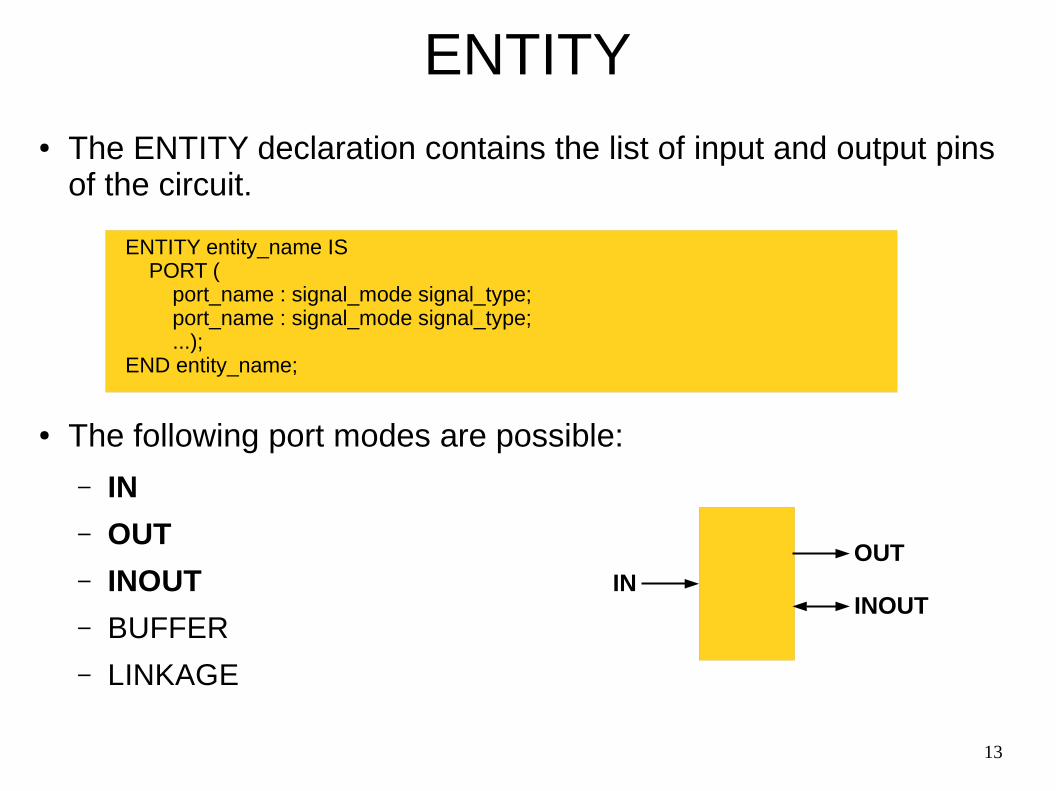
ENTITY● The ENTITY declaration contains the list of input and output pins
of the circuit.
● The following port modes are possible:
– IN
– OUT
– INOUT
– BUFFER
– LINKAGE
ENTITY entity_name IS PORT ( port_name : signal_mode signal_type; port_name : signal_mode signal_type; ...);END entity_name;
INOUT
INOUT

14
ENTITY Example
ENTITY nand_gate IS PORT (a, b : IN BIT; x : OUT BIT);END nand_gate;

15
ENTITY with GENERIC● The ENTITY can be parametrized:
ENTITY entity_name IS GENERIC (
parameter_name : parameter type;parameter_name : parameter type;
...) PORT ( port_name : signal_mode signal_type; port_name : signal_mode signal_type; ...);END entity_name;
INOUT
INOUT
n

16
Parametrized ENTITY Example
ENTITY nand_gate IS GENERIC(width : NATURAL := 8) PORT (a, b : IN BIT_VECTOR(width-1 downto 0); x : OUT BIT_VECTOR(width-1 downto 0));END nand_gate;
88
8

17
ARCHITECTURE
● ARCHITECTURE* describes, how the circuit should behave.
ARCHITECTURE architecture_name OF entity_name IS
[declarations]
BEGIN
(code)
END architecture_name;
*VHDL is case INSENSITIVE == vhdl IS CASE insensitive
Practical hint:- use small letters for keywords- use small letters or CamelStyle for names of variables, signals, functions- use capital letters for constants- be consistent

18
ARCHITECTURE - declarationsarchitecture architecture_name of entity_name is
-- CONSTANTS, e.g.: constant MASK : std_logic_vector(7 downto 0) := x”FF”;
-- SIGNALS, e.g.: signal internal_sum : integer;
-- TYPES, e.g.: type short_vector is array(3 downto 0) of std_logic;
-- FUNCTIONS / PROCEDURES, e.g.: function convert_vector_to_number(vec: short_vector) return natural is
… end function;
-- COMPONENTS, e.g.: component nand_gate is generic(width : natural := 8) port (a, b : in bit_vector(width-1 downto 0); x : out bit_vector(width-1 downto 0)); end component nand_gate;
begin
(code)
end architecture_name;
19
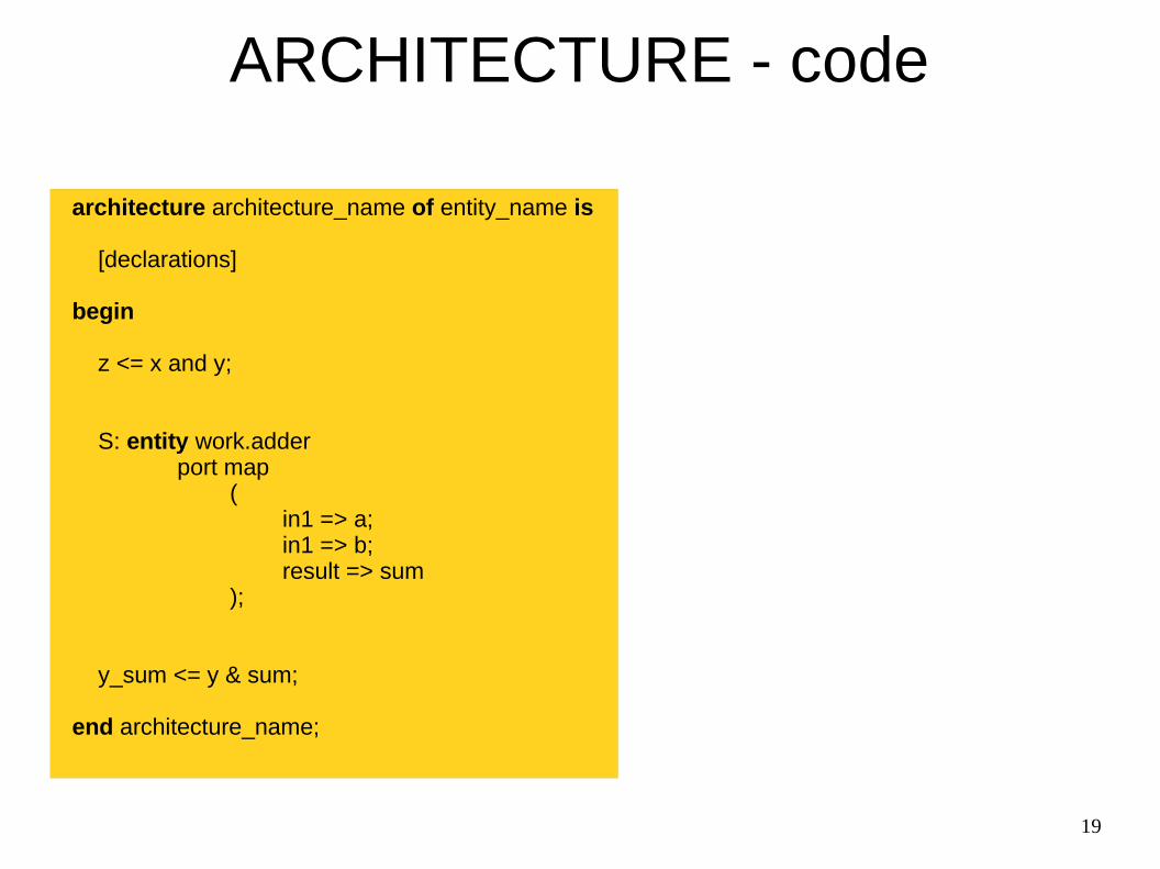
ARCHITECTURE - code
architecture architecture_name of entity_name is
[declarations]
begin
z <= x and y;
S: entity work.adderport map
(in1 => a;in1 => b;result => sum
);
y_sum <= y & sum;
end architecture_name;

20
Concurrent statements: pieces of hardware
architecture architecture_name of entity_name is
[declarations]
begin
z <= x and y;
S: entity work.adderport map
(in1 => a;in1 => b;result => sum
);
z_sum <= z & sum;
end architecture_name;
andx
zy
addera
sumb
z_sum
21
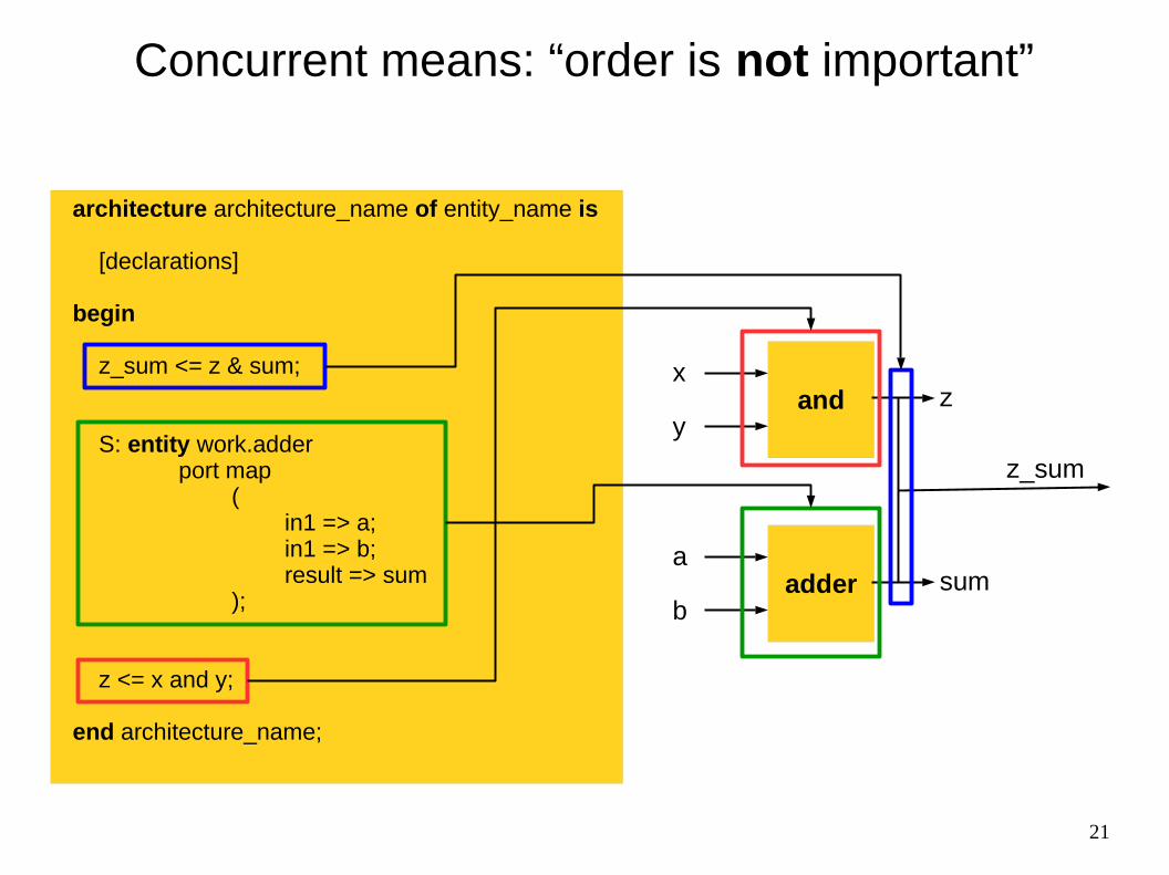
Concurrent means: “order is not important”
architecture architecture_name of entity_name is
[declarations]
begin
z_sum <= z & sum;
S: entity work.adderport map
(in1 => a;in1 => b;result => sum
);
z <= x and y;
end architecture_name;
andx
zy
addera
sumb
z_sum

22
CONFIGURATION - exampleentity my_entity is
port( a : in std_logic; b : out std_logic);
end entity;
-- =================================================architecture my_arch of my_entity is
component submodule isport( a : in std_logic; b : out std_logic);
end component;
begin
L1: submoduleport map (a => a, b => b);
end my_arch;
-- =================================================configuration my_config of my_entity is for my_arch for L1:submodule use entity work.similar_submodule(arch_1) end for; end for;end configuration;
“submodule” vs. “similar_submodule” - the names can be different, also the names of the ports can be different, types must allow mapping
“arch_1” - different architectures of the same entity can be defined and used when required

23
Two types of digital elements (combinational and sequential)

24
Digital Logic:Combinational vs Sequential
ab
q
clk
clk
a
b
q
a
b
f
a
b
f
asynchronous (“immediate”) changes
clock-synchronized changes

25
Combinational delaysab
q
clk
clk
a
b
q
a
b
f
a
b
f
clock-synchronized changes
Dt
asynchronous (“immediate”) changes

26
LUT – Look-up Table
00000001
a
b
c
f
LUT
000
001
010
011
100
101
110
111
f
00000001
a
b
c
LUTa b c f
0 0 0 0
0 0 1 0
0 1 0 0
0 1 1 0
1 0 0 0
1 0 1 0
1 1 0 0
1 1 1 1
Truth table Symbol Internal structure
27
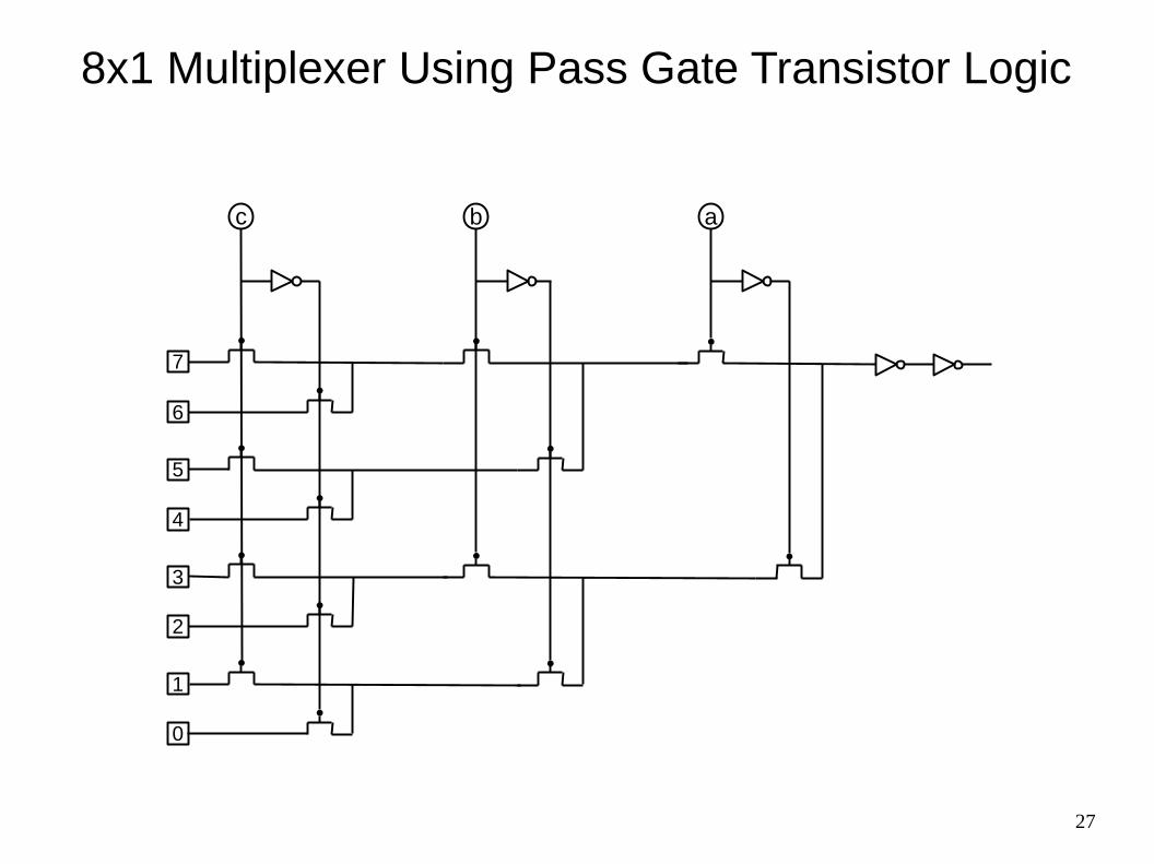
8x1 Multiplexer Using Pass Gate Transistor Logic
7
6
5
4
3
2
1
0
c b a
28
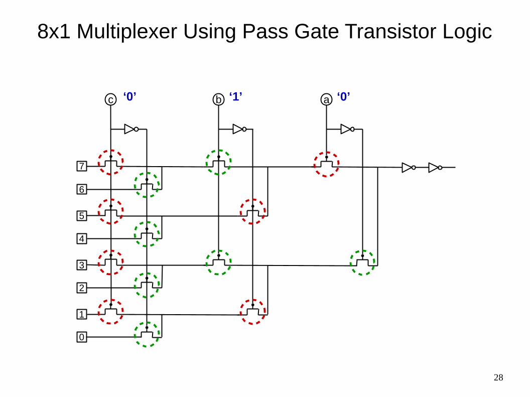
8x1 Multiplexer Using Pass Gate Transistor Logic
7
6
5
4
3
2
1
0
c b a‘0’ ‘1’ ‘0’

29
8x1 Multiplexer Using Pass Gate Transistor Logic
7
6
5
4
3
2
1
0
c b a‘0’ ‘1’ ‘0’

30
asynchronous (“immediate”) changes
Setup & Hold Time – No Input Changes Allowed
ab
q
clk
clk
a
b
q
a
b
f
a
b
f
clock-synchronized changes
th
ts hold time
setup time

31
Latch in CMOS
D
clk = 1 Q = D
D
clk = 0 Q = const
t1
t2

32
Flip-Flop in CMOS
t1
t2
D
clk = 0
Q = const
D
clk = 1
Q = const

33
Latch vs Flip-Flop in Timings
clk
D
QLatch
QFlip-Flop
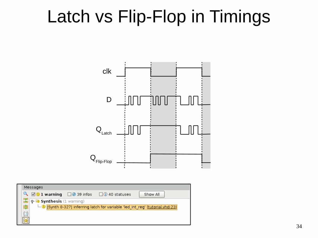
34
Latch vs Flip-Flop in Timings
clk
D
QLatch
QFlip-Flop
35
Basic concurrent statements

36
Concurrent Signal Assignmententity my_entity is
port( a : in std_logic; b : out std_logic);end entity;
architecture my_arch of my_entity is signal c : std_logic; signal d, e: std_logic_vector(7 downto 0); signal i, j, k: integer; signal t: boolean;begin
-- redirections b <= a; -- Ports can be used as signals c <= a; a <= c; -- ERROR: cannot write input port c <= b; -- ERROR: cannot read output port c <= d(3);
-- operations(1)
b <= a and c; -- logical, binary (and, or, nand, nor, xor, xnor) b <= not a; -- logical, unary
k <= i + j; -- arithmetical, binary (+, -, *, /, **, mod(2), rem(3)) k <= - j; -- arithmetical, unary (+, -, abs)
t <= (j <= i); -- relational (=, /=, <, <=, >, >=)
e <= d sll 3; -- shifts (sll, srl, sla, sra, rol, ror)
e <= d(4 downto 0) & “000”; -- concatenation
end my_arch;
(2) mod - rounds down, has sign of divisor(3) rem - rounds towards 0, has sign of dividend
(1) http://www.vhdl.renerta.com/mobile/source/vhd00047.htm

37
Component Instantiationentity my_entity is
port( a : in std_logic;b : out std_logic);
end entity;
-- =================================================architecture my_arch of my_entity is
component submodule_1 isport( a : in std_logic; b : out std_logic);
end component;
begin
L1: submodule_1port map (a => a, b => b); -- Named mapping
L2: submodule_1port map (a, b); -- Positional mapping (dangerous!)
L3: entity work.submodule_2 -- No component declaration requiredport map (a => a, b => b);
end my_arch;

38
Component Instantiationentity my_entity is
port( a : in std_logic;b : out std_logic);
end entity;
-- =================================================architecture my_arch of my_entity is
component submodule_1 isport( a : in std_logic; b : out std_logic);
end component;
begin
L1: submodule_1port map (a => a, b => b); -- Named mapping
L2: submodule_1port map (a, b); -- Positional mapping (dangerous!)
L3: entity work.submodule_2 -- No component declaration requiredport map (a => a, b => b);
end my_arch;
ERROR:XST:528 - Multi-source in Unit <my_entity> on signal <b>; this signal is connected to multiple drivers
ERROR:XST:528 - Multi-source in Unit <my_entity> on signal <b>; this signal is connected to multiple drivers

39
Simulations

40
Testing Using Graphical Tools
Specification of inputs
Analysis of waveforms

41
Testbench
Testing in VHDL
UUT
andx zy
addera sumb
z_sum
STIMULI (in VHDL)
x
y
a
b
VERIFICATION (in VHDL)
...wait 17 ns;assert z_sum = “0110”
report “Not Correct”severity ERROR
...

42
Testbench Has No Ports
entity my_entity_testbench isend entity;
-- =================================================architecture my_arch_testbench of my_entity_testbench is
signal a : std_logic;signal b : std_logic;
begin
UUT: entity work.my_entity(my_arch) port map (a => a, b => b);
-- STIMULI:a <= ...
-- VERIFICATION:...wait 17 ns;assert b = ‘1’ report “b is not 1” -- report printed when assertion fails severity WARNING -- type SEVERITY_LEVEL is (NOTE, WARNING, ERROR, FAILURE);...
end my_arch_testbench;
-- Unit Under Test (UUT)entity my_entity is
port( a : in std_logic; b : out std_logic);
end entity;
-- =================================================architecture my_arch of my_entity is...end my_arch;

43
Concurrent assignments with delays - NOT for SYNTHESIS
d <= ‘1’ after 5 ns, ‘0’ after 17 ns, ‘1’ after 32 ns, ‘Z’ after 51 ns;
clk <= not clk after 5 ns; -- PERIOD: 10 ns
x <= x1 after t1, x2 after t2, x3 after t3, … -- t1 < t2 < t3 ...
package STANDARD is(1)
...type time is range -2147483647 to 2147483647 units fs; ps = 1000 fs; ns = 1000 ps; us = 1000 ns; ms = 1000 us; sec = 1000 ms; min = 60 sec; hr = 60 min; end units; subtype delay_length is time range 0 fs to time'high;
(1) https://www.hdlworks.com/hdl_corner/vhdl_ref/VHDLContents/StandardPackage.htm

44
Inertial vs Transport Delay
10 ns
a
20 ns 30 ns 40 ns
b
a <= ‘1’ after 13 ns, ‘0’ after 15 ns;b <= a after 10 ns;
a <= ‘1’ after 13 ns, ‘0’ after 15 ns;b <= transport a after 10 ns;
10 ns
a
20 ns 30 ns 40 ns
b
Related Documents