Lecture 17 Small AC Signal Model of FET FET Small AC Signal Model 1-1 Wednesday 6/12/2017

Welcome message from author
This document is posted to help you gain knowledge. Please leave a comment to let me know what you think about it! Share it to your friends and learn new things together.
Transcript
Lecture 17
Small AC Signal Model of FET
FET Small AC Signal Model 1-1 Wednesday 6/12/2017

Outline Small AC Signal Equivalent Circuits for
FETs Amplifier Circuits Examples
Introduction to Power Electronics Power Semiconductor Devices
• Power MOSFET
FET Small AC Signal Model 1-2

Revisiting MOSFET
FET Small AC Signal Model 1-3
MOSFET Characteristics Curve
FET Small-Signal Model
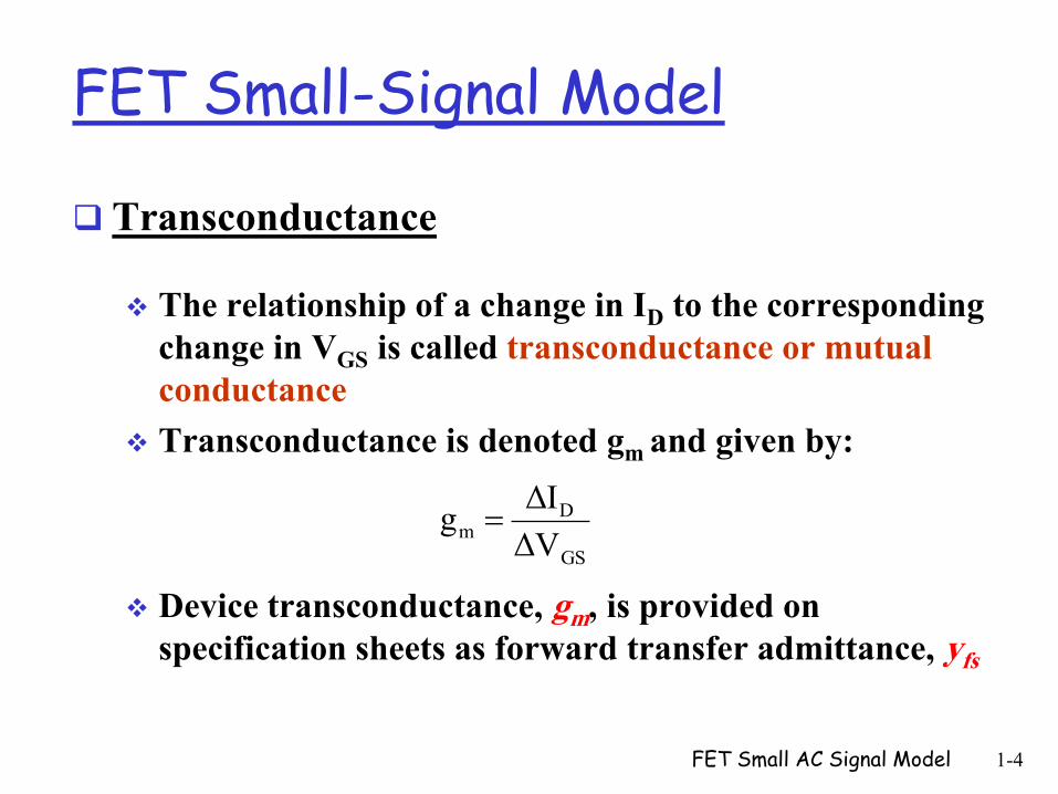
Transconductance
The relationship of a change in ID to the corresponding
change in VGS is called transconductance or mutual
conductance
Transconductance is denoted gm and given by:
Device transconductance, gm, is provided on
specification sheets as forward transfer admittance, yfs
FET Small AC Signal Model 1-4
GS
Dm
VΔ
IΔg

Graphical Determination of gm
FET Small AC Signal Model 1-5
Mathematical Definitions of gm
FET Small AC Signal Model 1-6
GS
Dm
V
Ig
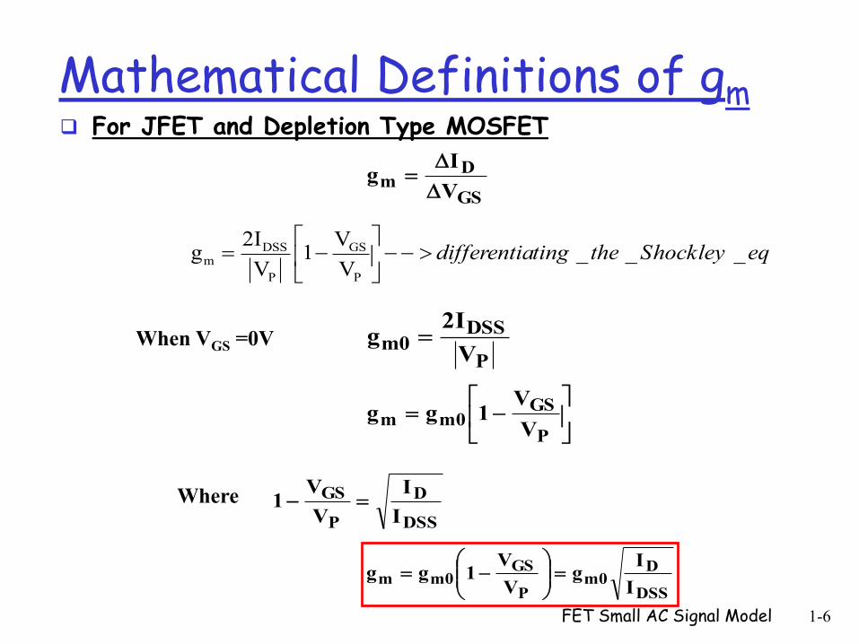
DSS GSm
P P
2I Vg 1 _ _ _
V Vdifferentiating the Shockley eq
P
DSSm0
V
2Ig
P
GSm0m
V
V1gg
DSS
D
P
GS
I
I
V
V1
DSS
Dm0
P
GSm0m
I
Ig
V
V1gg
When VGS =0V
Where
For JFET and Depletion Type MOSFET

Mathematical Definitions of gm
For Enhancement Type MOSFET
FET Small AC Signal Model 1-7
GS
Dm
V
Ig
K
I)VV( D
TGS
DD
m I2K
I2Kg K
Where
2
TGSD VVKI
TGSm VVK2g

FET AC Equivalent Circuit
FET Small AC Signal Model 1-8
Zi
osdo
y
1rZ
constant VD
DSd GSI
Vr
Input impedance:
Output Impedance:
where:
yos= output admittance parameter listed on FET specification sheets.
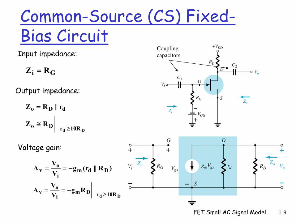
Common-Source (CS) Fixed-Bias Circuit
FET Small AC Signal Model 1-9
Gi RZ
dDo r||RZ
10RrDo
Dd
RZ
Input impedance:
Output impedance:
)R||(rgV
VA Ddm
i
ov
Dd 10RrDmi
ov Rg
V
VA
Voltage gain:
Coupling
capacitors
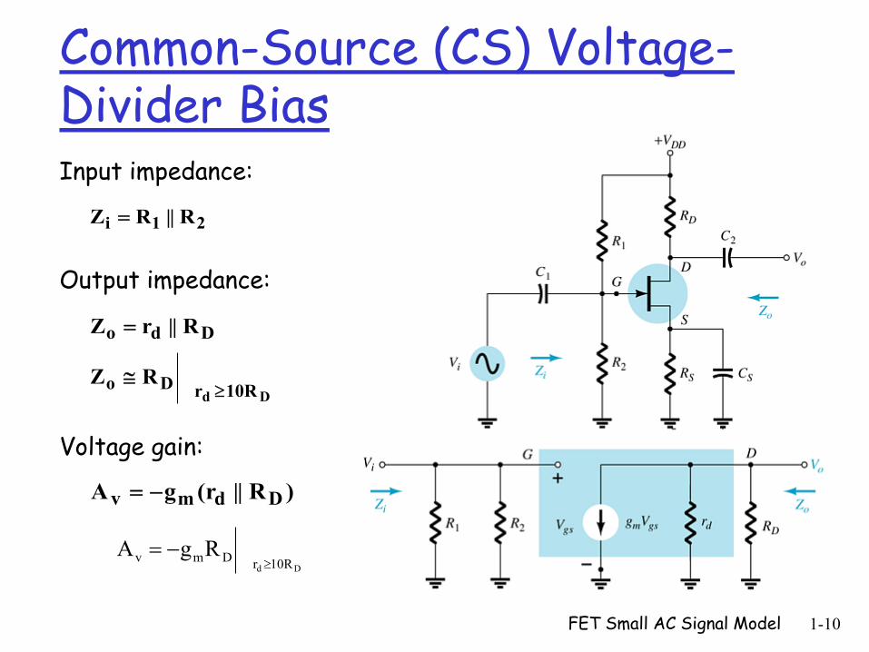
Common-Source (CS) Voltage-Divider Bias
FET Small AC Signal Model 1-10
21i R||RZ
Ddo R||rZ
10RrDo
Dd
RZ
Input impedance:
Output impedance:
)R||(rgA Ddmv
Dd 10RrDmv RgA
Voltage gain:

Example (1)
FET Small AC Signal Model 1-11
The fixed-bias configuration had an operating point defined by VGSQ = - 2 V and IDQ = 5.625 mA, with IDSS = 10 mA and VP = -8 V. The value of yos is provided as 40 μS.
(a) Determine gm
(b) Find rd
(c) Determine Zi
(d) Calculate Zo
(e) Determine the voltage gain Av
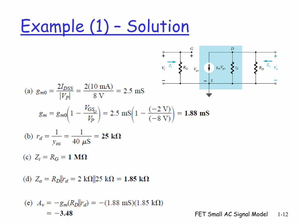
Example (1) – Solution
FET Small AC Signal Model 1-12

Small AC Signal Equivalent Model for MOSFET
- The ac equivalent model for MOSFETs is exactly the same as that employed for JFETs
- The only difference offered by D-MOSFETs is that VGSQ can be positive for n-channel devices and negative for p-channel units
- The result is that gm can be greater than gm0
FET Small AC Signal Model 1-13
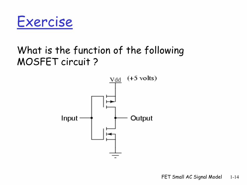
Exercise
What is the function of the following MOSFET circuit ?
FET Small AC Signal Model 1-14

MOSFET related Application
Complementary MOSFET Motor Controller
FET Small AC Signal Model 1-15
Power Electronics Technology
Power electronics is the application of solid-state (e.g., crystalline semiconductor) electronics for the control and conversion of electric power
The potential for applications of power electronics become wider used in a great variety of high power product, including heat
controls, light controls, electric motor control, power supplies, vehicle propulsion system and high voltage direct current (HVDC) systems
Many power semiconductor devices (e.g., power MOSFET) are available and directed to the field of power electronics A power semiconductor device is an electronic device that can
be used as switches in power electronic circuits FET Small AC Signal Model 1-16
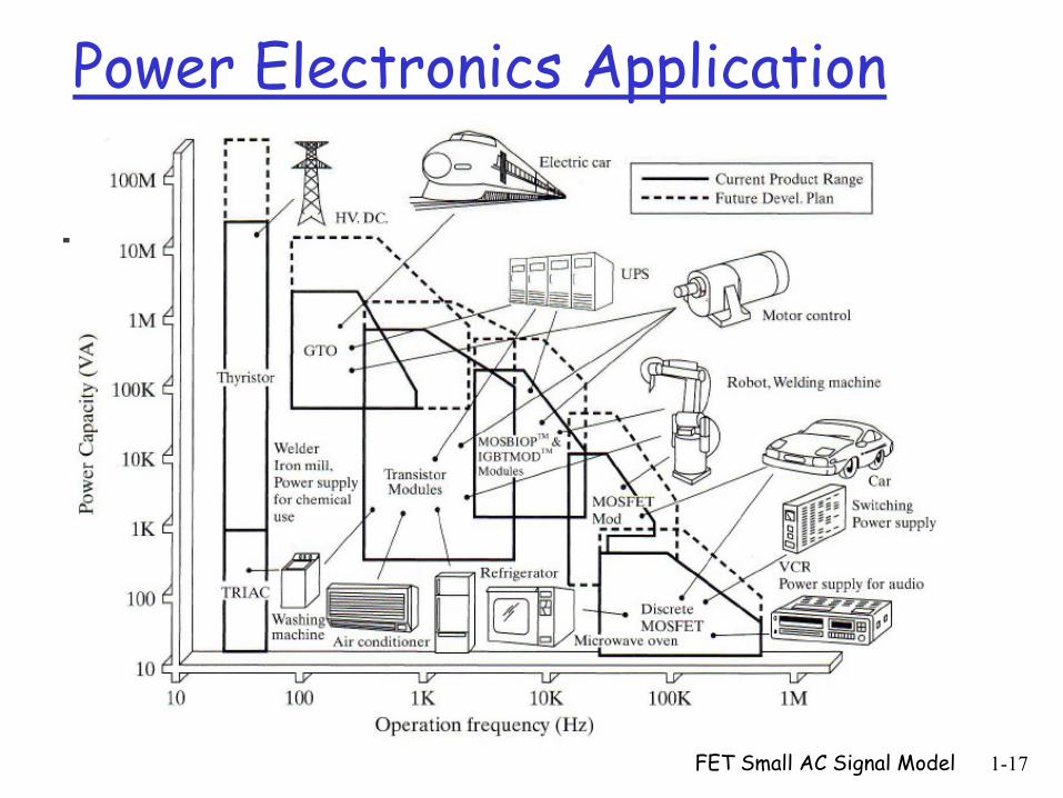
Power Electronics Application
FET Small AC Signal Model 1-17

Power Semiconductor Devices
Interesting parameters Breakdown voltage
On-resistance
Rise and fall times
Safe operating area
Thermal resistance
Different power transistors BJT (Bipolar Junction Transistor)
MOSFET (Metal Oxide Semiconductor Field effect transistor)
IGBT (Insulated Gate Bipolar Transistor) FET Small AC Signal Model 1-18
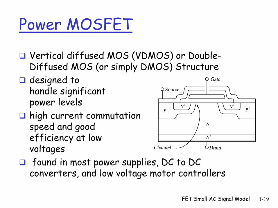
Power MOSFET
Vertical diffused MOS (VDMOS) or Double-Diffused MOS (or simply DMOS) Structure
designed to handle significant power levels
high current commutation speed and good efficiency at low voltages
found in most power supplies, DC to DC converters, and low voltage motor controllers
FET Small AC Signal Model 1-19
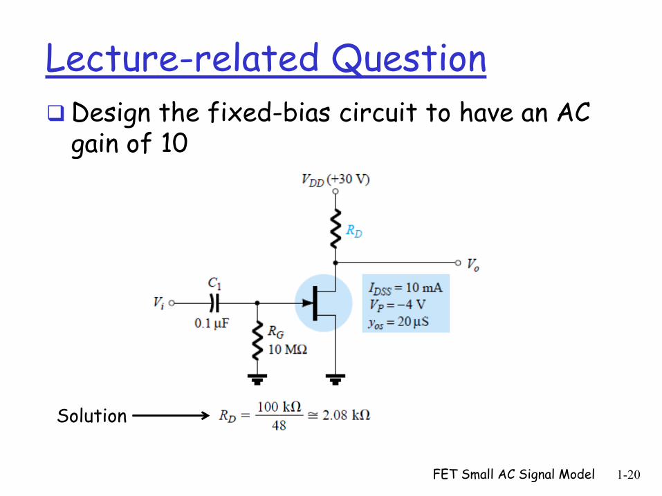
Lecture-related Question
Design the fixed-bias circuit to have an AC gain of 10
FET Small AC Signal Model 1-20
Solution

FET Small AC Signal Model 1-21
Lecture Summary
Covered material
Small AC Signal Equivalent Circuits for FETs Amplifier Circuits Examples
Introduction to Power Electronics Power Semiconductor Devices
• Power MOSFET
Material to be covered next lecture
Introduction to operational amplifiers and their applications
Related Documents