LECTURE 12 BIOREMEDIATION

Welcome message from author
This document is posted to help you gain knowledge. Please leave a comment to let me know what you think about it! Share it to your friends and learn new things together.
Transcript

LECTURE 12
BIOREMEDIATION

Bioremediation
Bioremediation is the use of microorganisms to destroy or immobilize waste materials
Microorganisms include:Bacteria (aerobic and anaerobic)FungiActinomycetes (filamentous bacteria)

Bioremediation mechanism
Microorganisms destroy organic contaminants in the course of using the chemicals for their own growth and reproductionOrganic chemicals provide:
carbon, source of cell building material electrons, source of energy
Cells catalyze oxidation of organic chemicals (electron donors), causing transfer of electrons from organic chemicals to some electron acceptor
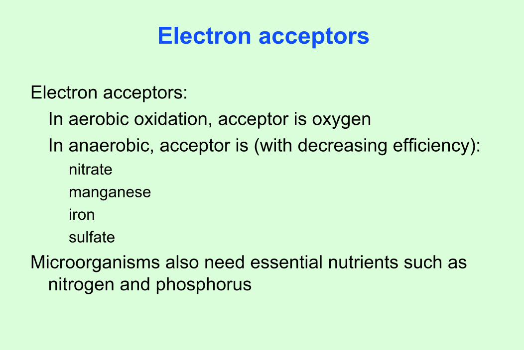
Electron acceptors
Electron acceptors:In aerobic oxidation, acceptor is oxygenIn anaerobic, acceptor is (with decreasing efficiency):
nitratemanganeseironsulfate
Microorganisms also need essential nutrients such as nitrogen and phosphorus
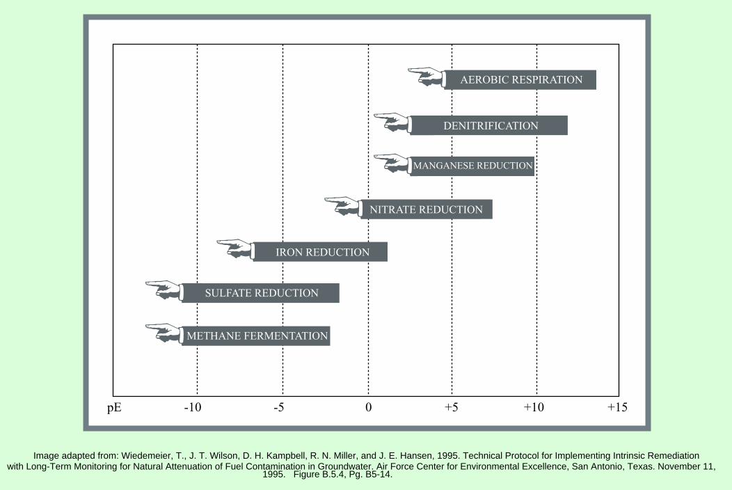
pE -10 -5 0 +5 +10 +15
AEROBIC RESPIRATION
IRON REDUCTION
SULFATE REDUCTION
NITRATE REDUCTION
MANGANESE REDUCTION
METHANE FERMENTATION
DENITRIFICATION
Image adapted from: Wiedemeier, T., J. T. Wilson, D. H. Kampbell, R. N. Miller, and J. E. Hansen, 1995. Technical Protocol for Implementing Intrinsic Remediationwith Long-Term Monitoring for Natural Attenuation of Fuel Contamination in Groundwater. Air Force Center for Environmental Excellence, San Antonio, Texas. November 11,
1995. Figure B.5.4, Pg. B5-14.
Bacterial growth
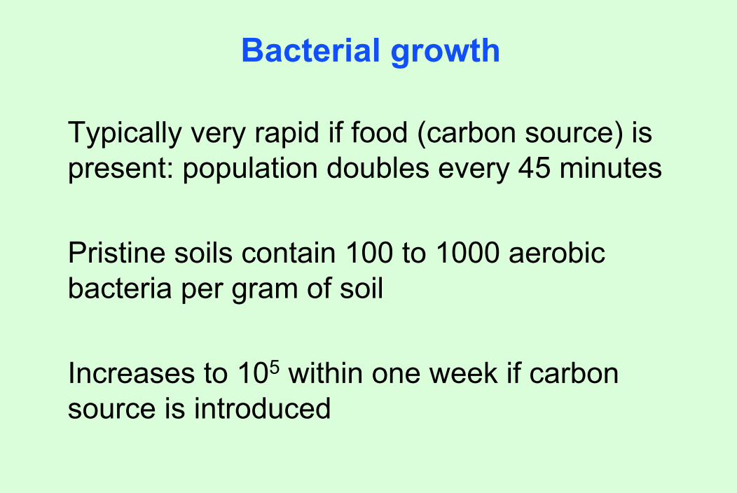
Typically very rapid if food (carbon source) is present: population doubles every 45 minutes
Pristine soils contain 100 to 1000 aerobic bacteria per gram of soil
Increases to 105 within one week if carbon source is introduced
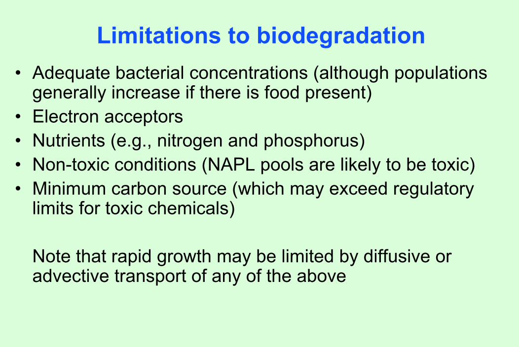
Limitations to biodegradation• Adequate bacterial concentrations (although populations
generally increase if there is food present)• Electron acceptors• Nutrients (e.g., nitrogen and phosphorus)• Non-toxic conditions (NAPL pools are likely to be toxic)• Minimum carbon source (which may exceed regulatory
limits for toxic chemicals)
Note that rapid growth may be limited by diffusive or advective transport of any of the above

History of bioremediation
1972 - First commercial application: Sun Oil pipeline spill in Ambler, Pennsylvania
1970s - Continuing bioremediation projects by Richard Raymond of Sun Oil
mid-1980s - emphasis on bioengineering organisms for bioremediation. This technology did not live up to its initial promise
1990s - emphasis switched to greater reliance on natural microorganisms and techniques to enhance their performance
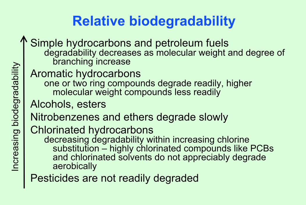
Relative biodegradabilitySimple hydrocarbons and petroleum fuels
degradability decreases as molecular weight and degree of branching increase
Aromatic hydrocarbonsone or two ring compounds degrade readily, higher
molecular weight compounds less readilyAlcohols, estersNitrobenzenes and ethers degrade slowlyChlorinated hydrocarbons
decreasing degradability within increasing chlorine substitution – highly chlorinated compounds like PCBs and chlorinated solvents do not appreciably degrade aerobically
Pesticides are not readily degraded
Incr
easi
ng b
iode
grad
abili
ty
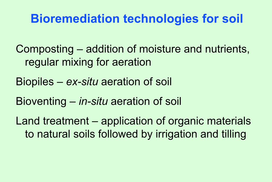
Bioremediation technologies for soil
Composting – addition of moisture and nutrients, regular mixing for aeration
Biopiles – ex-situ aeration of soil
Bioventing – in-situ aeration of soil
Land treatment – application of organic materials to natural soils followed by irrigation and tilling
Composting
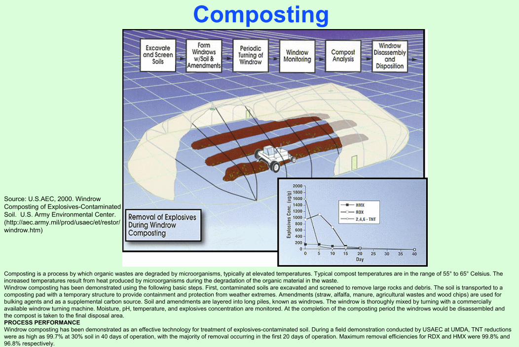
Source: U.S.AEC, 2000. Windrow Composting of Explosives-Contaminated Soil. U.S. Army Environmental Center. (http://aec.army.mil/prod/usaec/et/restor/windrow.htm)
Composting is a process by which organic wastes are degraded by microorganisms, typically at elevated temperatures. Typical compost temperatures are in the range of 55° to 65° Celsius. The increased temperatures result from heat produced by microorganisms during the degradation of the organic material in the waste. Windrow composting has been demonstrated using the following basic steps. First, contaminated soils are excavated and screened to remove large rocks and debris. The soil is transported to a composting pad with a temporary structure to provide containment and protection from weather extremes. Amendments (straw, alfalfa, manure, agricultural wastes and wood chips) are used for bulking agents and as a supplemental carbon source. Soil and amendments are layered into long piles, known as windrows. The windrow is thoroughly mixed by turning with a commercially available windrow turning machine. Moisture, pH, temperature, and explosives concentration are monitored. At the completion of the composting period the windrows would be disassembled and the compost is taken to the final disposal area. PROCESS PERFORMANCEWindrow composting has been demonstrated as an effective technology for treatment of explosives-contaminated soil. During a field demonstration conducted by USAEC at UMDA, TNT reductions were as high as 99.7% at 30% soil in 40 days of operation, with the majority of removal occurring in the first 20 days of operation. Maximum removal efficiencies for RDX and HMX were 99.8% and96.8% respectively.

Composting
See image at the Web site of Resource Recovery Systems of Nebraska, Inc., KV Compost Equipment, Windrow Composting. http://www.rrskw.com/windrow_composting.htm.Accessed May 11, 2004.
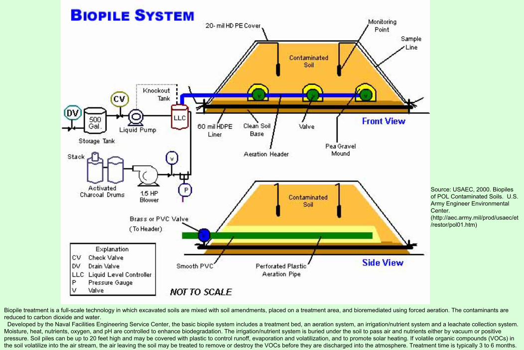
Source: USAEC, 2000. Biopilesof POL Contaminated Soils. U.S. Army Engineer Environmental Center. (http://aec.army.mil/prod/usaec/et/restor/pol01.htm)
Biopile treatment is a full-scale technology in which excavated soils are mixed with soil amendments, placed on a treatment area, and bioremediated using forced aeration. The contaminants are reduced to carbon dioxide and water. Developed by the Naval Facilities Engineering Service Center, the basic biopile system includes a treatment bed, an aeration system, an irrigation/nutrient system and a leachate collection system.
Moisture, heat, nutrients, oxygen, and pH are controlled to enhance biodegradation. The irrigation/nutrient system is buried under the soil to pass air and nutrients either by vacuum or positive pressure. Soil piles can be up to 20 feet high and may be covered with plastic to control runoff, evaporation and volatilization, and to promote solar heating. If volatile organic compounds (VOCs) in the soil volatilize into the air stream, the air leaving the soil may be treated to remove or destroy the VOCs before they are discharged into the atmosphere. Treatment time is typically 3 to 6 months.
Biopile
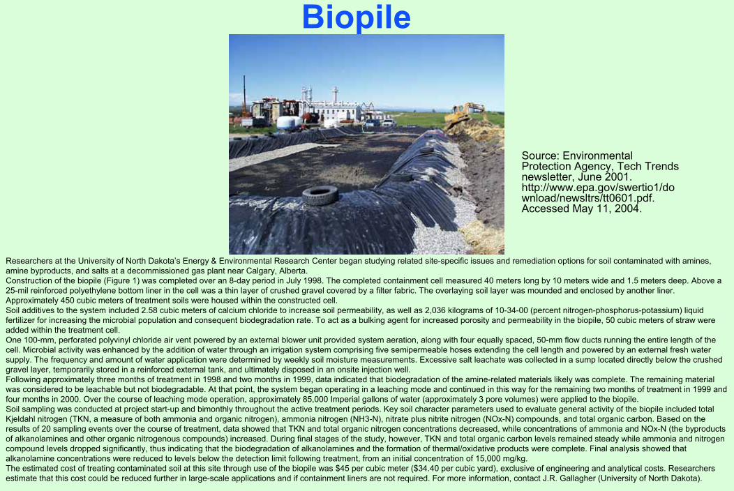
Source: Environmental Protection Agency, Tech Trends newsletter, June 2001. http://www.epa.gov/swertio1/download/newsltrs/tt0601.pdf. Accessed May 11, 2004.
Researchers at the University of North Dakota’s Energy & Environmental Research Center began studying related site-specific issues and remediation options for soil contaminated with amines, amine byproducts, and salts at a decommissioned gas plant near Calgary, Alberta. Construction of the biopile (Figure 1) was completed over an 8-day period in July 1998. The completed containment cell measured 40 meters long by 10 meters wide and 1.5 meters deep. Above a 25-mil reinforced polyethylene bottom liner in the cell was a thin layer of crushed gravel covered by a filter fabric. The overlaying soil layer was mounded and enclosed by another liner. Approximately 450 cubic meters of treatment soils were housed within the constructed cell. Soil additives to the system included 2.58 cubic meters of calcium chloride to increase soil permeability, as well as 2,036 kilograms of 10-34-00 (percent nitrogen-phosphorus-potassium) liquid fertilizer for increasing the microbial population and consequent biodegradation rate. To act as a bulking agent for increased porosity and permeability in the biopile, 50 cubic meters of straw were added within the treatment cell. One 100-mm, perforated polyvinyl chloride air vent powered by an external blower unit provided system aeration, along with four equally spaced, 50-mm flow ducts running the entire length of the cell. Microbial activity was enhanced by the addition of water through an irrigation system comprising five semipermeable hoses extending the cell length and powered by an external fresh water supply. The frequency and amount of water application were determined by weekly soil moisture measurements. Excessive salt leachate was collected in a sump located directly below the crushed gravel layer, temporarily stored in a reinforced external tank, and ultimately disposed in an onsite injection well. Following approximately three months of treatment in 1998 and two months in 1999, data indicated that biodegradation of the amine-related materials likely was complete. The remaining material was considered to be leachable but not biodegradable. At that point, the system began operating in a leaching mode and continued in this way for the remaining two months of treatment in 1999 and four months in 2000. Over the course of leaching mode operation, approximately 85,000 Imperial gallons of water (approximately 3 pore volumes) were applied to the biopile. Soil sampling was conducted at project start-up and bimonthly throughout the active treatment periods. Key soil character parameters used to evaluate general activity of the biopile included total Kjeldahl nitrogen (TKN, a measure of both ammonia and organic nitrogen), ammonia nitrogen (NH3-N), nitrate plus nitrite nitrogen (NOx-N) compounds, and total organic carbon. Based on the results of 20 sampling events over the course of treatment, data showed that TKN and total organic nitrogen concentrations decreased, while concentrations of ammonia and NOx-N (the byproducts of alkanolamines and other organic nitrogenous compounds) increased. During final stages of the study, however, TKN and total organic carbon levels remained steady while ammonia and nitrogen compound levels dropped significantly, thus indicating that the biodegradation of alkanolamines and the formation of thermal/oxidative products were complete. Final analysis showed that alkanolamine concentrations were reduced to levels below the detection limit following treatment, from an initial concentration of 15,000 mg/kg. The estimated cost of treating contaminated soil at this site through use of the biopile was $45 per cubic meter ($34.40 per cubic yard), exclusive of engineering and analytical costs. Researchers estimate that this cost could be reduced further in large-scale applications and if containment liners are not required. For more information, contact J.R. Gallagher (University of North Dakota).
Biopile aeration system
See image at the Web site of Flinders Bioremediation, Pty., Full-Scale Bioremediation. http://www.scieng.flinders.edu.au/biology/research/Bioremediation/html/full.html.Accessed May 11, 2004.

Biopile performance on TPH
Site Name Summary Beginning Levels
Levels Attained
Costs
Marine Corps Mountain Warfare Training Center Bridgeport,CA
Pilot study at fuel-leaking UST site-aerated soil pile on lined bed
TPH 1,200 ppm 120 ppm after 2 months
$88/metric ton ($80/ton)
Marine Corps Air Ground Combat Center Twenty-Nine Palms, CA
Fuel from UST and spills research project
702 ppm average TPH
234 ppm average
$6/m³($27/yd³)
Note: 1 m3 ≈ 1.5 metric ton
Source: USAEC, 2000. Biopiles of POL Contaminated Soils. U.S. Army Engineer Environmental Center. (http://aec.army.mil/prod/usaec/et/restor/pol01.htm)

Requirements for soil bioremediation
Environmental Factor Optimum conditions
Available soil moisture 25-85% water holding capacity
Oxygen >0.2 mg/L DO, >10% air-filled pore space for aerobic degradation
Redox potential Eh > 50 millivolts
Nutrients C:N:P = 120:10:1 molar ratio
pH 5.5 to 8.5
Temperature 15-45ºC

Example design calculations
Moisture for biopile375 yd3 gasoline-contaminated soil with otherwise low organic contentAssume: porosity, n = 30%
initial saturation, S = 20%Desired water content = 25 to 85%, use 60%Water needed = 375 yd3 (0.30) (0.6 – 0.2) = 45 yd3
= 1215 ft3 = 9,090 gallons
Example design calculations
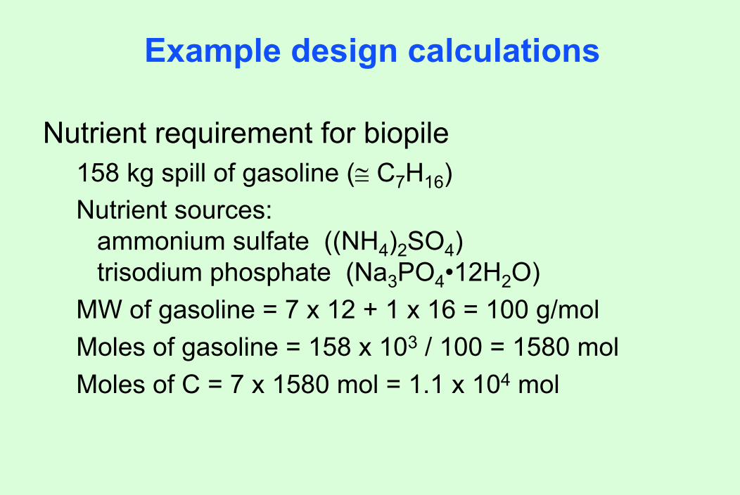
Nutrient requirement for biopile158 kg spill of gasoline (≅ C7H16)Nutrient sources:
ammonium sulfate ((NH4)2SO4)trisodium phosphate (Na3PO4•12H2O)
MW of gasoline = 7 x 12 + 1 x 16 = 100 g/molMoles of gasoline = 158 x 103 / 100 = 1580 molMoles of C = 7 x 1580 mol = 1.1 x 10⁴ mol

Example design calculations
Molar ratio C:N:P = 120:10:1Moles of N needed = 10/120 x 1.1 x 104 = 920 molMoles of ((NH4)2SO4) needed = 920 / 2 = 460 molMW of ((NH4)2SO4) = (14 + 4) x 2 + 32 + 4 x 16 = 132Mass of ((NH4)2SO4) needed = 132 g/mol x 460 mol
= 6.1 x 10⁵ g = 61 kgBy similar calculation:Mass of (Na3PO4•12H2O) needed = 35 kg

Example design calculations
Oxygen requirement for biopileC7H16 + 22O2 → 7CO2 + 8H2O 1 mole (100 g) gasoline requires 22 moles (704 g) O2
Oxygen content of air = 21% by volume = 210,000 ppmv
1 ppmv = 1 atm x 32 g/mol 1000 mg/g x 0.0821 L atm/(mol ºK) x 293 ºK
= 0.00133 mg/L2.1 x 105 ppmv = 280 mg/L = 0.28 g/L

Example design calculations
Oxygen needed for 158 kg spill of gasoline (≅ C7H16)100 g gasoline needs ~700 g oxygen158 kg gasoline x 7 = 1106 kg O2 = 1.1 x 10⁶ g O2
Water in pile = 375 yd3 (0.30) (0.6) = 67.5 yd3
= 52 m3 = 52,000 LAt saturation at 20ºC and 1 atm, DO = 9.2 mg/L
Mass of oxygen in soil moisture = = 52,000 L x 9.2 mg/L x 0.001 g/mg= 480 g O2

Example design calculations
480 g O2 in soil moisture is much less than 1.1 x 10⁶
g O2 requiredAt 0.28 g/L air, air requirement is:
1.1 x 10⁶ g / 0.28 g/L = 3.95 x 10⁶ L air = 3,950 m3 air
Air void volume in pile = 375 yd3 (0.30) (0.4) = 45 yd3 = 34 m3
Need to exchange 3950 / 34 = 116 void volumes to fulfill oxygen requirement

Bioventing
Source: USAEC, 2000. Bioventing of POL Contaminated Soils. U.S. Army Environmental Center. (http://aec.army.mil/prod/usaec/et/restor/pol03.htm)
Developed by the Air Force Center for Environmental Excellence, bioventing stimulates the in-situ biodegradation of POLs by providing oxygen to microorganisms in the soil. The system supplies oxygen by injecting air directly into the residual contamination (see below). In contrast to soil vapor vacuum extraction (SVE), bioventing uses low airflow rates to provide only enough oxygen to sustain microbial activity. Optimal flow rates maximize biodegradation as vapors move slowly through biologically active soil while minimizing volatilization of contaminants. A basic bioventing system includes a well and a blower, which pumps air through the well and into the soil. Bioventing has been approved in 38 states and all 10 Environmental Protection Agency (EPA) regions.

BioventingSiteName
Summary BeginningLevels
1 YearResults
Costs
Fort RuckerSWMU 14
JP-4 fuel, motor oil, tanker truck washout fluids from a waste disposal pit.
TPH=25,000 mg/kgBTEX=10 mg/kg
AverageTPH=16.9 mg/kgBTEX not detected
$60K for 20,000 cubic yards of oxygenated soil ($3/cubic yard)
Fort CarsonBldg. 8200
Petroleum contaminated soils from USTs at a former fueling system. Increased cost due to 12-inch concrete pad over the site.
BTEX=17 mg/kgTPH=1,350 mg/kg
TPH reduction rate of 170 mg/kg/yr.
$119K for 6,500 cubic yards of oxygenated soil ($18.31/cubic yard)
Fort BlissBldg. 675
Petroleum contaminated soils at 18 to 55 feet below ground from leaking UST.
AverageBTEX=1,350 mg/kg
BTEX=690 mg/kg
$73K for 12,700 cubic yards of oxygenated soil
Fort Drum Bulk Fuel Storage Area 1595
Pilot scale field test.Petroleum contaminated soil.
AverageTPH=15,00 mg/kgBTEX=8.6 mg/kg
TPH=600 mg/kgBTEX=0.25 mg/kg
Not available
Source: USAEC, 2000. Bioventing of POL Contaminated Soils. U.S. Army Environmental Center. (http://aec.army.mil/prod/usaec/et/restor/pol03.htm)

Bioremediation technology for floating product
Bioslurping – two-phase vapor extraction that also encourages biodegradation

Source: USAEC, 2000. Bioslurping of POL Contaminated Soils. U.S. Army Environmental Center. (http://aec.army.mil/prod/usaec/et/restor/pol02.htm)
Now comes a dynamic new technology that accomplishes both actions at once. Bioslurping teams vacuum-assisted free-product recovery with bioventing to simultaneously recover free product and remediate the vadose zone. Developed by the Air Force Center for Environmental Excellence, the bioslurper system uses a "slurp" tube that extends into the free-product layer. Much like a straw draws soda and air through
crushed ice in a drinking glass, the pump draws liquid (including free product) and soil gas up the tube in the same process stream. The driving force of the vacuum provides better product recovery than conventional methods that rely only on gravity. The product flow proceeds horizontally, reducing the entrapment or "smearing" typical of conventional pump systems. Bioventing occurs as the system extracts soil gas from the subsurface - oxygen flow from the entering air promotes aerobic biodegradation throughout the affected vadose zone and capillary fringe.

Bioremediation technologies for ground water
Bioremediation - addition of one or more of the following to stimulate bacterial growth:NutrientsCarbon source (dextrose, molasses)OxygenCirculation

Amendment introduction methods
Injection wellsInfiltrationPassive introduction of chemicals

Amendment introduction via injection wells
Organic Amendment Zone
Groundwater Flow DirectionInjected
Amendment
GROUNDWATER LEVEL
Ground Surface
Extent of Dissolved Contaminant Plume
Amendment Injection Wells
DNAPL
Reactive Zone: Area of Enhanced Contaminant Degradation
AQUITARD
Amendment introduction via trenches
See image at the Web site of Enzyme Technologies, Inc., “MTBE and BTEX Degradation Using Enzyme-catalyzed Dissolved Oxygen In Situ Treatment Gas Station Site, Cheshire, CT.” http://www.enzymetech.com/projects/20-A/chesh_sp/chesh_sp.pdf. Accessed May 11, 2004.
Bioremediation - infiltration
See image at the Web site of Enzyme Technologies, Inc., “MTBE and BTEX Degradation Using Enzyme-catalyzed Dissolved Oxygen In Situ Treatment Gas Station Site, Cheshire, CT.” http://www.enzymetech.com/projects/20-A/chesh_sp/chesh_sp.pdf. Accessed May 11, 2004.
Total BTEX Reduction
See image at the Web site of Enzyme Technologies, Inc., “MTBE and BTEX Degradation Using Enzyme-catalyzed Dissolved Oxygen In Situ Treatment Gas Station Site, Cheshire, CT.” http://www.enzymetech.com/projects/20-A/chesh_sp/chesh_sp.pdf. Accessed May 11, 2004.

Amendment introduction via passive introduction
Oxygen release compound (magnesium peroxide):
MgO2 + H2O → ½ O2 + Mg(OH)2
Oxygen Release Compound (ORC)
See images at the Web site of Regenesis Bioremediation Products, Inc., ORC Images. http://www.regenesis.com/products/orc/images.aspx. Accessed May 11, 2004.
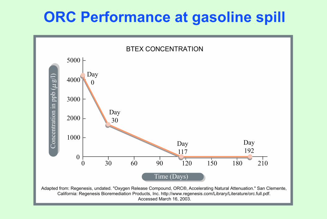
ORC Performance at gasoline spill
30
Day30
Day0
Day117
Day192
60 90 120 150 180 21000
1000
2000
3000
4000
5000
BTEX CONCENTRATION
Adapted from: Regenesis, undated. "Oxygen Release Compound, ORC®, Accelerating Natural Attenuation." San Clemente, California: Regenesis Bioremediation Products, Inc. http://www.regenesis.com/Library/Literature/orc.full.pdf.
Accessed March 16, 2003.
Con
cent
ratio
n in
ppb
( g
/l)µ
Time (Days)

Amendments to create anaerobic conditions
Carbon sources:AcetatePropionateEthanolLactateMolassesVegetable oilHRC (Lactic acid)
Panciera, Matthew A., Olga Zelennikov, Barth F. Smets, Gregory M. Dobbs, 2001. Differential stimulation of haloreduction by carbon addition to subsurface soils. In: Sixth Annual In-Situ and On-Site Bioremediation Conference, San Diego, CA, June 3-7, 2001. Battelle Press, Columbus, OH. http://www.regenesis.com/pdf%20files/Battell%2001%20abs.paper/PANCIERA%20ZELENNIKOVA%20SMETS%20and%20DOBBS%20-%20B2001%20-%20Abs.pdf

Hydrogen release compound
See image at the Web site of RegenesisBioremediation Products, Inc., http://www.regenesis.com/library/HRC%20Brochure.pdfAccessed May 11, 2004.

HRC Case Study
00
20
4060
80100120140
160180
50 100 150
PCE, TCE, DCE & VC Mass ChangesHRC Field Demonstration in WI
PCE,
TC
E &
DC
E in
gra
ms
& V
C in
mill
igra
ms
200 250 300
Adapted from: Regenesis, undated. "Hydrogen Release Compound (HRC®)." Case History #H-1.1,HRC Field Demonstration Cedarburgh, Wisconsin. San Clemente, California: Regenesis Bioremediation
Products, Inc. http://www.regenesis.com/Library/Case_Histories/HRC_Case%20Hist/HRC_Case_History_H1.1.htm.Accessed March 16, 2003.
VC
TCE
DCE
PCE
Time (days)

Broome County Landfill Site, New York Pump and treat remedy
Pump and treat system:$2.5 million capital$350,000 annual O&M$6.8 million present value
Broome County Landfill Web site: http://www.gobroomecounty.com/dpw/DPWLandfill.php
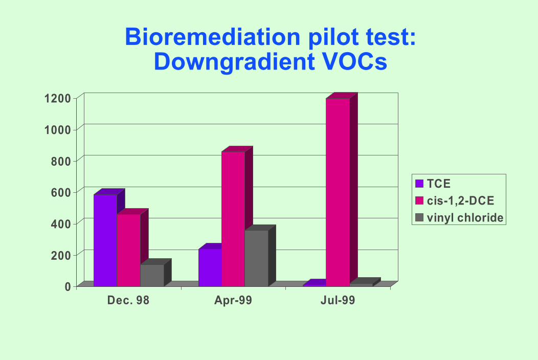
Downgradient VOCs
0
200
400
600
800
1000
1200
Dec. 98 Apr-99 Jul-99
TCEcis-1,2-DCEvinyl chloride
Bioremediation pilot test:
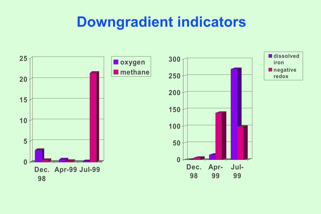
Downgradient indicators
0
5
10
15
20
25
Dec.98
Apr-99 Jul-99
oxygenmethane
0
50
100
150
200
250
300
Dec.98
Apr-99
Jul-99
dissolvedironnegativeredox
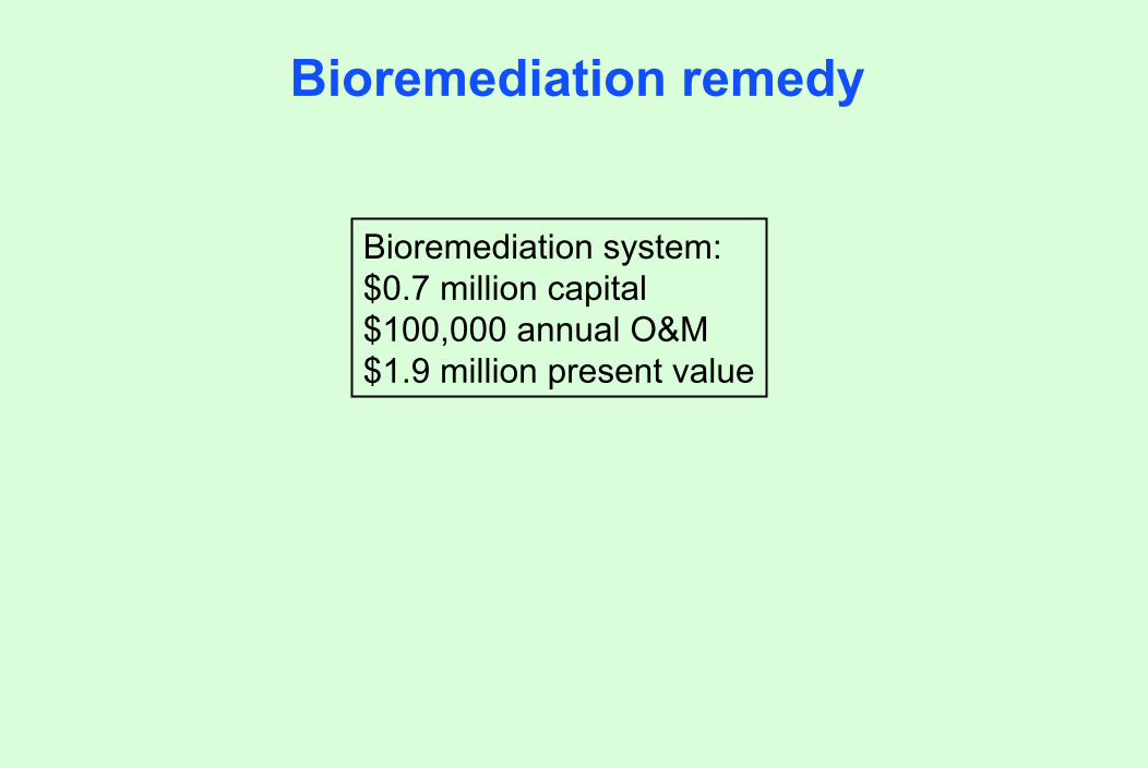
Bioremediation remedy
Bioremediation system:$0.7 million capital$100,000 annual O&M$1.9 million present value

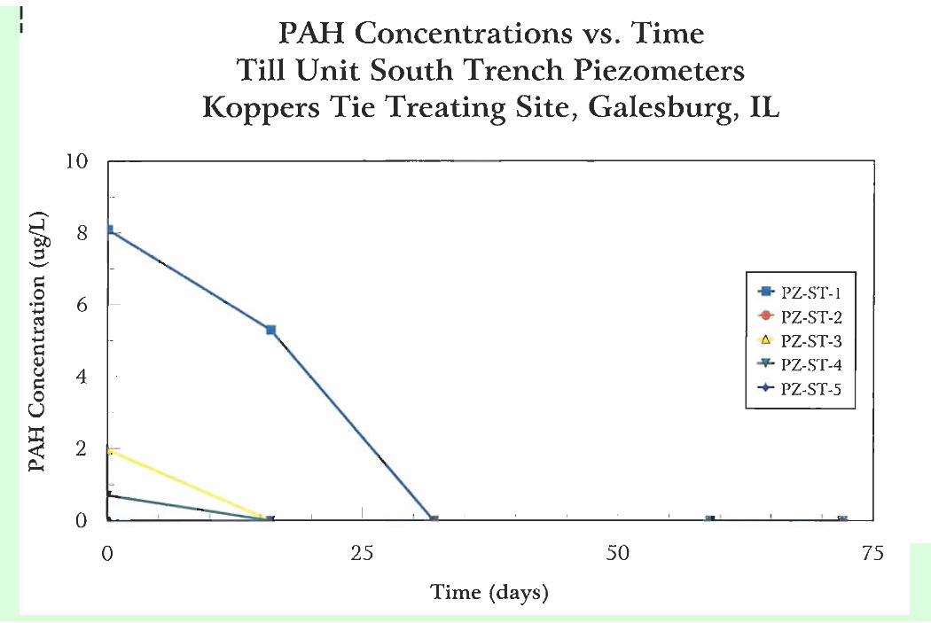
Koppers Superfund Site, Galesburg, IL
Till Layer
Groundwater Flow
Aquifer Air Flow
Horizontal Pipes Slotted onBottom in 10 Sections
Along Trench
Unsaturated Zone
Well/Piezometer Ports@ Each Section Along Trench
Potential Source
Dissolved Constituent
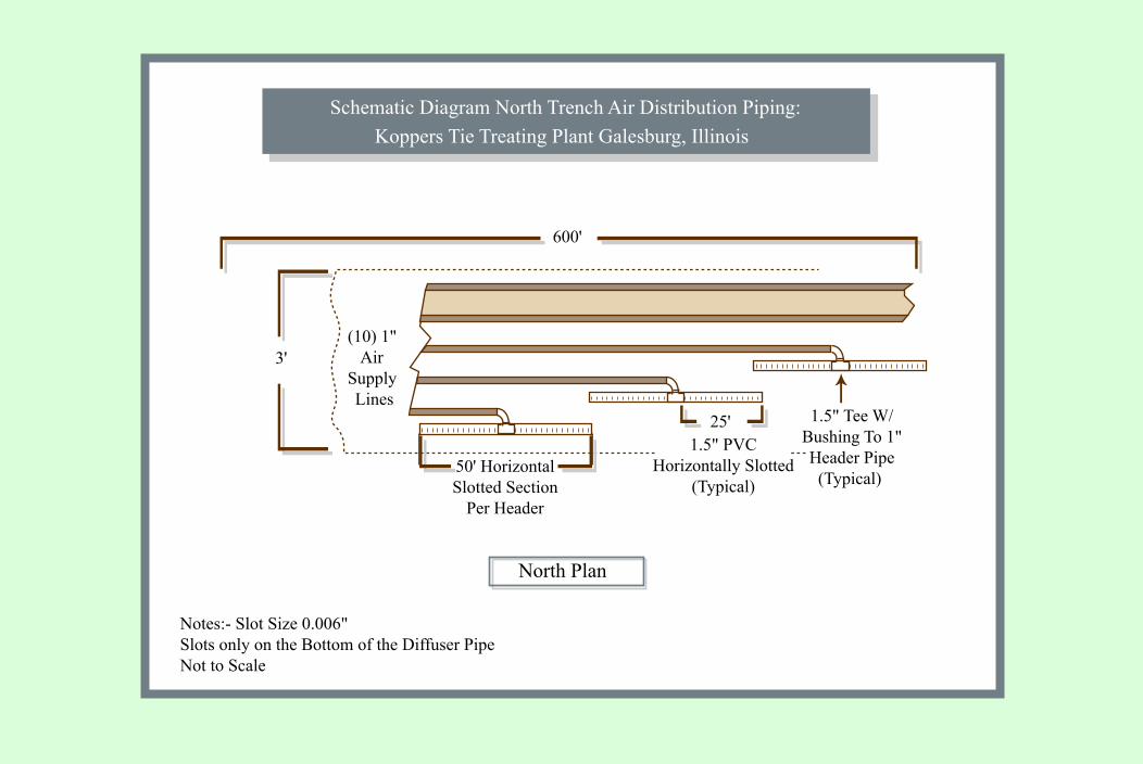
Microbial Fence System Schematic: Koppers Tie Treating Site, Galesburg, Illinois

600'
3'
50' Horizontal Slotted Section
Per Header
Notes:- Slot Size 0.006"Slots only on the Bottom of the Diffuser PipeNot to Scale
North Plan
25'1.5" PVC
Horizontally Slotted(Typical)
1.5" Tee W/Bushing To 1"Header Pipe
(Typical)
(10) 1" Air
Supply Lines
600'
3'
50' Horizontal Slotted Section
Per Header
Notes:- Slot Size 0.006"Slots only on the Bottom of the Diffuser PipeNot to Scale
North Plan
Schematic Diagram North Trench Air Distribution Piping:Koppers Tie Treating Plant Galesburg, Illinois
25'1.5" PVC
Horizontally Slotted(Typical)
1.5" Tee W/Bushing To 1"Header Pipe
(Typical)
(10) 1" Air
Supply Lines

PREDICTED CONCENTRATION OF NAPHTHALENE AT RECEPTOR WELL
With Soil Removal
0
0.2
0.4
0.6
0.8
0 10000 20000 30000 40000 50000Time (years)
Con
cent
ratio
n (m
g/l)
Without Soil Removal

Compressor Building
Well with ORC socksSW - 4SW - 3 SW - 5
304B
308C
SW - 2SW - 1
Trestle
PZ-NT-4
308CBaseline 1.252 Hours 3.7
Existing PiezometerExisting Monitoring WellBuildingEstimated Limit of Elevated Dissolved OxygenEnd of Northern TrenchRailroad Tracks
SW-1Baseline 1.452 Hours 5.8
SW-5Baseline 1.452 Hours 4.2
304BBaseline 1.952 Hours 1.2
SW-4Baseline 2.152 Hours 5.1
Dissolved Oxygen (mg/L) Sand Aquifer Pilot Test WellsKoppers Tie Treating Plant Galesburg, Illinois

Affected by DNAPL?
Affected by ORC

DO history after ORC removal
Related Documents