Lecture # 10 Electrolysis & Energy Storage Ahmed F. Ghoniem March 4, 2020 • Storage technologies, for mobile and stationary applications.. • Fuel Cells and Electrolysis, some more electrochemistry.. • CO 2 reduction/reuse via electrolysis Shi, Yu et al in Literature/Luo Yu Electrolysis …. © Ahmed F. Ghoniem 1

Welcome message from author
This document is posted to help you gain knowledge. Please leave a comment to let me know what you think about it! Share it to your friends and learn new things together.
Transcript
Lecture # 10
Electrolysis & Energy Storage
Ahmed F. Ghoniem March 4, 2020
• Storage technologies, for mobile and stationary applications.. • Fuel Cells and Electrolysis, some more electrochemistry.. • CO2 reduction/reuse via electrolysis
Shi, Yu et al in Literature/Luo Yu Electrolysis ….
© Ahmed F. Ghoniem 1

Energy Storage Capacity
© Source unknown. All rights reserved. This content is excluded from our Creative Commons license. For more information, see https://ocw.mit.edu/fairuse.
Chris Mutty and Scott Seo 2019 paper for reference 2
)SM
g n l ) R s s d n s s sae y ii ii lln no os s s smc t eyi y yi Wii yin tt tct cl l r l laoe a oi oaei r eclr c m tr rp hte i dy i a tcf f ts r cf p c oi ie ose es er o rl a Gea ssr e e h l tt e( gg ct otadwa ee ss PVl Phrmia ln ar eaCo gi lo ol So(l mo Bia tss oc oiGa i s PhBim yle oh rtc co em Elre
Th
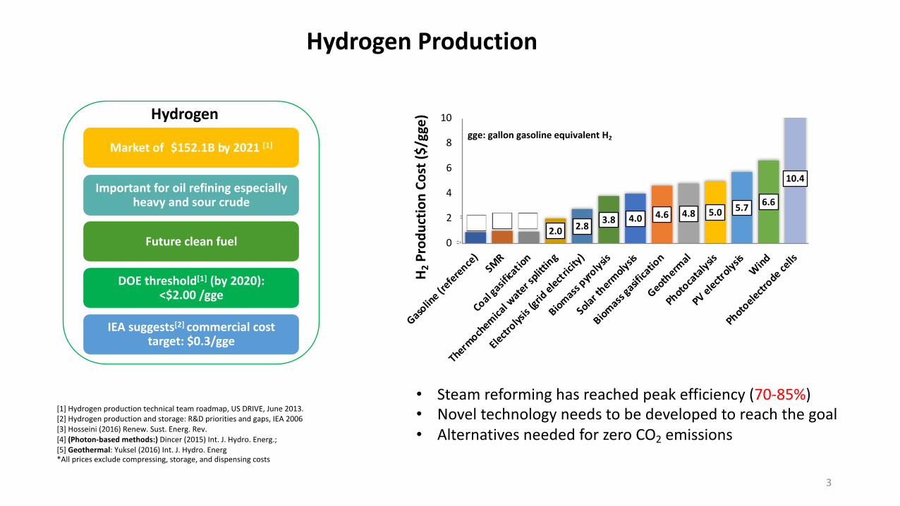
Hydrogen Production
Market of $152.1B by 2021 [1]
Important for oil refining especiallyheavy and sour crude
Future clean fuel
DOE threshold[1] (by 2020):<$2.00 /gge
IEA suggests[2] commercial cost target: $0.3/gge
Hydrogen
0.9 1.0 1.0 2.0 2.8 3.8 4.0 4.6 4.8 5.0 5.7 6.6
10.4
0
2
4
6
8
10 gge: gallon gasoline equivalent H2
H 2 P
rodu
ctio
n Co
st ($
/gge
) • Steam reforming has reached peak efficiency (70-85%)
[1] Hydrogen production technical team roadmap, US DRIVE, June 2013. • Novel technology needs to be developed to reach the goal[2] Hydrogen production and storage: R&D priorities and gaps, IEA 2006 [3] Hosseini (2016) Renew. Sust. Energ. Rev. [4] (Photon-based methods:) Dincer (2015) Int. J. Hydro. Energ.; • Alternatives needed for zero CO2 emissions [5] Geothermal: Yuksel (2016) Int. J. Hydro. Energ *All prices exclude compressing, storage, and dispensing costs
3
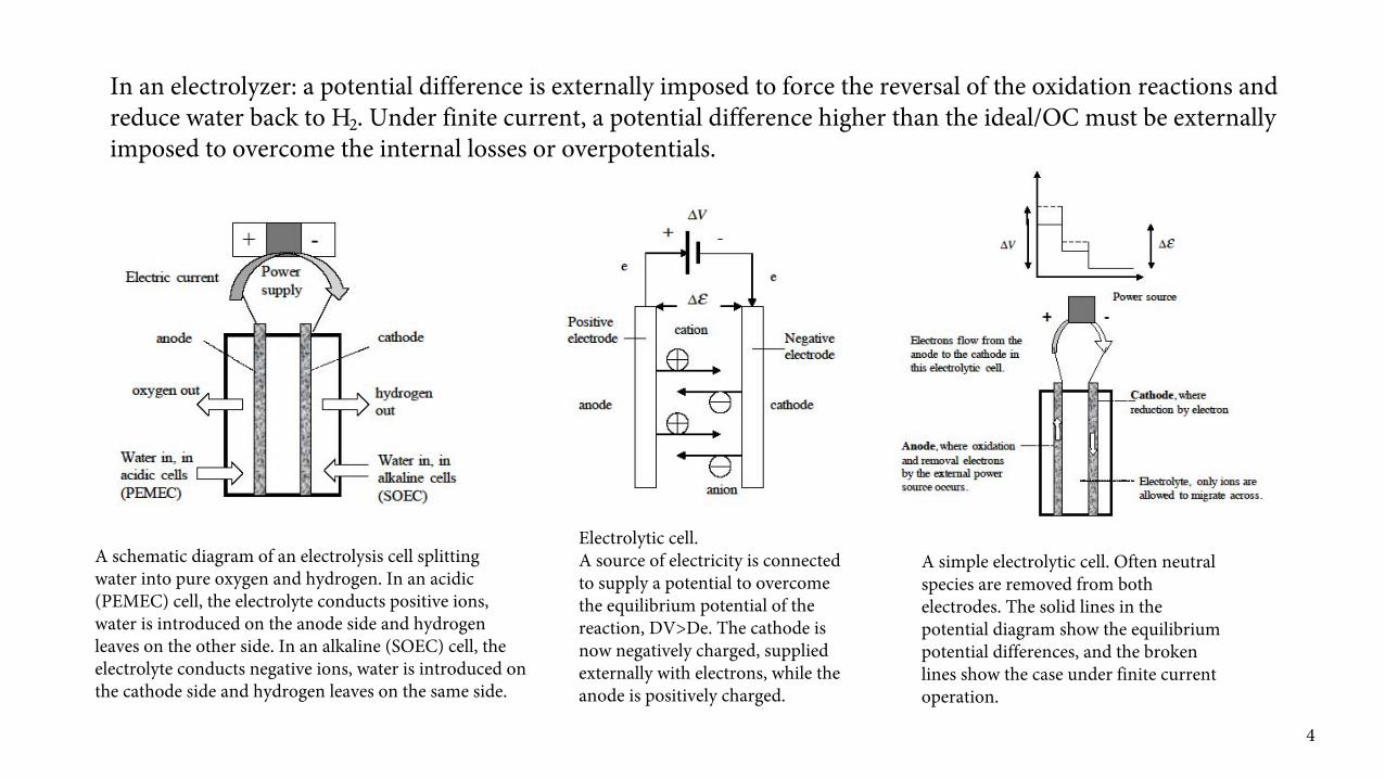
In an electrolyzer: a potential difference is externally imposed to force the reversal of the oxidation reactions and reduce water back to H . Under finite current, a potential difference higher than the ideal/OC must be externally2
imposed to overcome the internal losses or overpotentials.
A schematic diagram of an electrolysis cell splitting water into pure oxygen and hydrogen. In an acidic (PEMEC) cell, the electrolyte conducts positive ions, water is introduced on the anode side and hydrogen leaves on the other side. In an alkaline (SOEC) cell, the electrolyte conducts negative ions, water is introduced on the cathode side and hydrogen leaves on the same side.
Electrolytic cell. A source of electricity is connected to supply a potential to overcome the equilibrium potential of the reaction, DV>De. The cathode is now negatively charged, supplied externally with electrons, while the anode is positively charged.
A simple electrolytic cell. Often neutral species are removed from both electrodes. The solid lines in the potential diagram show the equilibrium potential differences, and the broken lines show the case under finite current operation.
4

Electrolysis reduces water back to H2
Can be used to store an “infinite” amount of energy (from electricity) in the form of chemical energy Operates as the reverse of a fuel cell
Overall Reaction: 1H2O → H2 + O2 with ΔHR ~ 242 kJ/mol_H2 and ΔGR ~ 224 kJ/mol_H22
In an acidic (electrolyte transporting +ve ions) cell (PEM): 1H2O → O2 + 2H+ + 2e- and 2H+ + 2e− → H22
In an alkline (electrolyte transporting -ve ions) cell: 12H2O + 2e− → H2 + 2OH− and 2OH− → O2 + 2e− + H2O2
In Solid Oxide (electrolyte transporting -ve ions) cells: (SOEC) H2O + 2e− → H2 + O2− and 2O2- → O2 + 4e-
© Source unknown. All rights reserved. This content is excluded from our Creative Commons license. For more information, see https://ocw.mit.edu/fairuse.
5

(SOEC) (AEC) (PEM):
2H2O + 2e− → H2 + 2OH− 1 H2O + 2e− → H2 + O2− H2O → O2 + 2H+ + 2e-
2 2OH− →
1 O2 + 2e− + H2O 2O2- → O2 + 4e-
2 2H+ + 2e− → H2
Courtesy Elsevier, Inc., http://www.sciencedirect.com. Used with permission.
6

CO2 Reuse
Solid Oxide Electrolysis and Fuel Cells
Electrolysis can be used to split water and/or CO2 But similar to SOFC’s the high T solid oxide type is more compatible with CO2 splitting
1CO2 → CO + O2 ΔHR ~ 280 kJ/mol_CO 2
In an alkalyine (electrolyte transporting -ve ion) SOEC cell: CO2 + 2e− → CO + O2−
2O2- → O2 + 4e-
Oxygen electrode O2- –> ½O2+2e-
Fuel electrode H2O+2e- –> H2+O2-
CO2+2e- –> CO+O2-
Oxygen electrode ½O2+2e- –> O2-
Fuel electrode H2+O2- –> H2O+2e-
CO+O2- –> CO2+2e-
2e-
From wind, solar, nuclear
O2
+
SOEC -
H2O H2 CO2 CO
O2
+ SOFC 2e-
Powers motors, bulbs, etc. -
H2O H2 CO2 CO
7

Electrolysis reduces water back to H2Can be used to store an “infinite” amount of energy (from electricity) in the form of chemical energy
Operates as the reverse of a fuel cell
The thermodynamics are very similar to that of a fuel cell
QQ − W = ΔHR and = ΔSR= Hout − Hin = Sout − SinT *
(−W = H − TS )out − H − TS ( = ΔHR − TΔSR)in
W = −ΔGR and Q = TΔSR
Q = TΔSR = ΔHR − ΔGR
reversing the original (FC) reaction, we have ΔHR > 0 and ΔGR > 0In electrolysis, both work is added and heat is added (when ΔHR > ΔGR )
A fuel cell produces work and rejects heat, an electrolyzer needs both
8
Q H2/CO
W
Oxygen H2O/CO2 Chemical
reactions @ T *
Environment
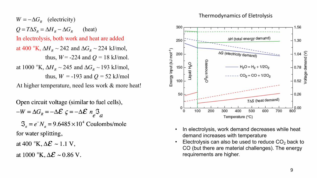
W = −ΔGR (electricity) Q = TΔSR = ΔHR − ΔGR (heat) In electrolysis, both work and heat are added
at 400 oK, ΔHR ~ 242 and ΔGR ~ 224 kJ/mol, thus, W = -224 and Q = 18 kJ/mol.
at 1000 oK, ΔHR ~ 245 and ΔGR ~ 193 kJ/mol, thus, W = -193 and Q = 52 kJ/mol
At higher temperature, need less work & more heat!
Thermodynamics of Eletrolysis
• In electrolysis, work demand decreases while heat demand increases with temperature
• Electrolysis can also be used to reduce CO2 back to CO (but there are material challenges). The energy requirements are higher.
9

Electrolysis for production of H2 and/or co-production of H2/CO and synthesis fuels
(a) Single element(b) A stack
© Wiley. All rights reserved. This content is excluded from our Creative Commons license. For more information, see https://ocw.mit.edu/fairuse.
Shi et al, Handbook of Clean Energy Systems, 2015, Wiley 10

At finite current, an electrolyzer suffers from the same losses as a FC, generating positive internal voltage drop that must be compensated for externally,
+ ! + !ΔεEC = Δε o + η!a,act + η!a,conc ηa,FU + η!el ,oh + η!c,act + η!c,conc ηa,FU
η! ≡ (positive) overpotential
Therefore, the imposed external potential difference in electrolysis must be higher than the open circuit potential. The difference between the actual imposed potential difference and the open circuit values are expected to be of the same order of magnitude to those in fuel cells, at the same current (see two sides arrows in figure).
In this case, the difference between the ideal work and actual work is heat dissipated in the cell, which is typically the heat required by first law analysis.
Reversible voltage (zero current) and actual voltage of an electrolyzer at finite current at different T. Lower T reduces the OC voltage, but at finite current, kinetics are sluggish and diffusivity is lower leading to more losses and higher operating voltage
11
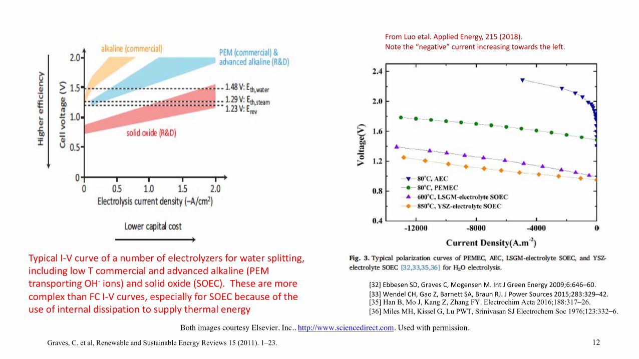
Typical I-V curve of a number of electrolyzers for water splitting, including low T commercial and advanced alkaline (PEM transporting OH- ions) and solid oxide (SOEC). These are more complex than FC I-V curves, especially for SOEC because of the use of internal dissipation to supply thermal energy
From Luo etal. Applied Energy, 215 (2018). Note the “negative” current increasing towards the left.
[32] Ebbesen SD, Graves C, Mogensen M. Int J Green Energy 2009;6:646–60. [33] Wendel CH, Gao Z, Barnett SA, Braun RJ. J Power Sources 2015;283:329–42. [35] Han B, Mo J, Kang Z, Zhang FY. Electrochim Acta 2016;188:317–26. [36] Miles MH, Kissel G, Lu PWT, Srinivasan SJ Electrochem Soc 1976;123:332–6.
Both images courtesy Elsevier, Inc., http://www.sciencedirect.com. Used with permission.
Graves, C. et al, Renewable and Sustainable Energy Reviews 15 (2011). 1–23. 12

At finite current, it is not necessary to supply heat to the electrolysis cell externally, internal dissipation is
sufficient to generate the necessary heat. Therefore only electricity is needed, at the actual potential
(including the overpotentials) required to run the electrolysis reactions. The heat generation rate is I(V-Voc).
Several efficiencies are usually defined: a second law efficiency, and a first law like efficiency which can be
based on either the enthalpy or Gibbs free energy of the produced hydrogen:
= ΔεOC ηII Δε
JH 2 i Δ ⌢hR,H2=ηthermal i i Δε
JH 2 i ΔGR,H2=ηwork i i Δε
Anode Cathode Electrolyte T (C) Cell Voltage (V) ηth ηII IrO2 10%Pt Vulcan Nafion 80 1.65 89.70% 74.55%
Ir0.6Ru0.4O2 20%Pt/C Nafion 115 90 1.567 94.45% 78.49%
IrO2 Pt/C Nafion 112 80 1.63 90.80% 75.46%
Ir0.5Ru0.5O2 Pt/C Nafion 112 80 1.65 89.70% 74.55%
Ir Pt/C Nafion 112 80 1.72 86.05% 71.51%
Ru Pt/C Nafion 112 80 1.79 82.68% 68.72%
IrO2 nano film 20%Pt/C Nafion 117 80 1.83 80.87% 67.21%
Ir Black Pt/Vulcan XC72 Nafion 115 90 1.7 87.06% 72.35%
Ir Black Pd/Vulcan XC72 Nafion 115 90 1.67 88.62% 73.65%
Ir Black Co(dmg) Nafion 115 90 2.45 60.41% 50.20%
Ir Black α-H4SiW12O40 Nafion 115 90 2 74.00% 61.50%
20%RuO2/ATO (SnO2)
50%Pt/C Nafion 212 80 1.56 94.87% 78.85%
Efficiency of a number of PEMEC. Note that the conditions at which these efficiency were determined could be very different, that is, the current or hydrogen production rate. The thermal efficiency is higher than the voltage efficiency because of the internal use of the heat generated by dissipation (Le Chang). 13
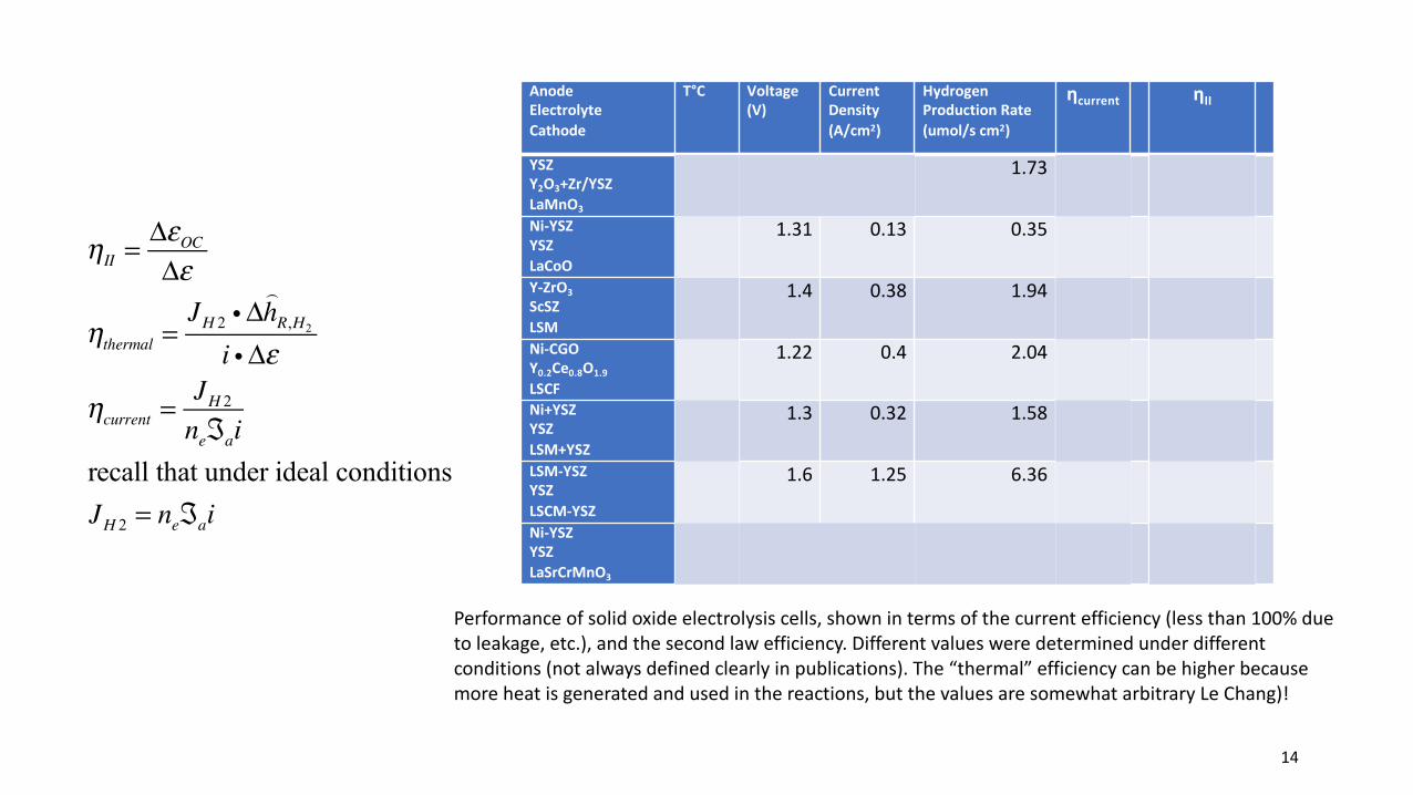
ΔεOC ηII = Δε
JH 2 i Δh⌢ R,H2=ηthermal i i Δε
JH 2=ηcurrent neℑai recall that under ideal conditions
JH 2 = neℑai
Anode Electrolyte Cathode
T°C Voltage (V)
Current Density (A/cm2)
Hydrogen Production Rate (umol/s cm2)
ηcurrent ηII
YSZ Y2O3+Zr/YSZ LaMnO3
997 1.32 0.37 1.73 90.2% 61.56%
Ni-YSZ YSZ LaCoO
950 1.31 0.13 0.35 51.9% 36.28%
Y-ZrO3 ScSZ LSM
900 1.4 0.38 1.94 98.5% 65.43%
Ni-CGO Y0.2Ce0.8O1.9
LSCF
820 1.22 0.4 2.04 98.4% 76.94%
Ni+YSZ YSZ LSM+YSZ
750 1.3 0.32 1.58 95.2% 71.44%
LSM-YSZ YSZ LSCM-YSZ
850 1.6 1.25 6.36 98.2% 57.98%
Ni-YSZ YSZ LaSrCrMnO3
770 1.29 0.35 1.82 100% 75.11%
Performance of solid oxide electrolysis cells, shown in terms of the current efficiency (less than 100% due to leakage, etc.), and the second law efficiency. Different values were determined under different conditions (not always defined clearly in publications). The “thermal” efficiency can be higher because more heat is generated and used in the reactions, but the values are somewhat arbitrary Le Chang)!
14

MIT OpenCourseWare https://ocw.mit.edu/
2.60J Fundamentals of Advanced Energy Conversion Spring 2020
For information about citing these materials or our Terms of Use, visit: https://ocw.mit.edu/terms.
Related Documents