VLSI DESIGN JYOTI YADAV

Welcome message from author
This document is posted to help you gain knowledge. Please leave a comment to let me know what you think about it! Share it to your friends and learn new things together.
Transcript

VLSI DESIGNJYOTI YADAV
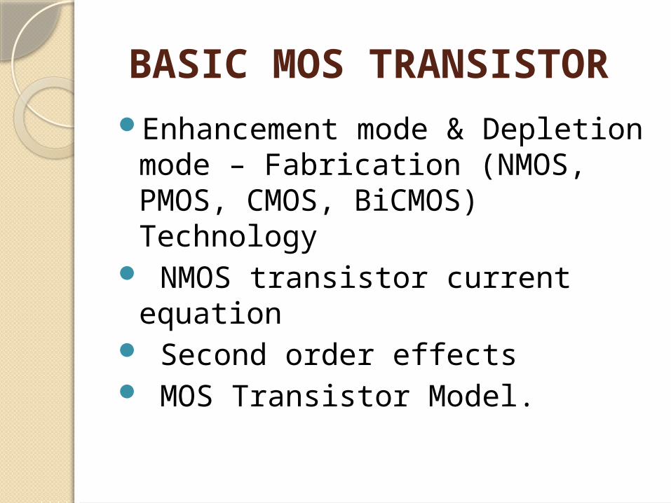
BASIC MOS TRANSISTOR
Enhancement mode & Depletion mode – Fabrication (NMOS, PMOS, CMOS, BiCMOS) Technology
NMOS transistor current equation
Second order effects MOS Transistor Model.

Required BookD.A.Pucknell, K.Eshraghian,
„Basic VLSI Design‟,
Neil H.E. Weste and Kamran Eshraghian; Principles of CMOS VLSI Design
Pratima Manhas by Katraia & Sons

HistoryT-R-A-N-S-I-S-T-O-R =
TRANsfer resiSTOR

Levels of IntegrationSSI: - (10-100) transistors
◦ Example: Logic gates MSI: - (100-1000)
◦ Example: counters LSI: - (1000-20000)
◦ Example: 8-bit chip VLSI: - (20000-1000000)
◦Example: 16 & 32 bit up ULSI: - (1000000-10000000)
◦Example: Special processors, virtual reality machines, smart sensors.

Moore‟s LawNumber of transistors embedded
on the chip doubles after every one and a half years.
Transistors become smaller, faster, consume less power, and are cheaper to manufacture
No other technology has grown so fast so long


Comparison of available technologies

GaAs technology is better but still it is not used because of growing difficulties of GaAs crystal
CMOS looks to be a better option compared to nMOS since it consumes a lesser power.
BiCMOS technology is also used in places where high driving capability is required and from the graph it confirms that, BiCMOS consumes more power compared to CMOS

Silicon LatticeSilicon is a semiconductor Transistors are built on a silicon
substrate Silicon is a Group IV material Forms crystal lattice with bonds
to four neighbors

DopantsPure silicon has no free carriers and
conducts poorlyAdding dopants increases the
conductivity Group V: extra electron (n-type)Group III: missing electron, called
hole (p-type)

Basic MOS TransistorsMetal Oxide Semiconductor
transistor Structure consists of a layer of
Metal (gat e), a layer of oxide (Sio2) and a layer of semiconductor.
Four terminals: gate, source, drain, body

CONT..
The phenomenon used to control the current in a semiconductor, by applying an electric field perpendicular to the surface is called the field effect.
The basic transistor principle is that the voltage between two terminals controls the current through the third terminal.

Sl No BJT MOSFET1 It is a Bipolar Device It is majority carrier Device
2 Current control Device Voltage control Device.
3 Output is controlled by controlling base current
Output is controlled by controlling gate voltage
4 Negative temperature coefficient Positive temperature coefficient
5 So paralleling of BJT is difficult. So paralleling of MOSFET is easy.
6 Losses are low. Losses are higher than BJTs.
7 So used in high power applications. Used in low power applications.
8 BJTs have high voltage and current ratings.
MOSFETs have less voltage and current ratings.
9 Switching frequency is lower than MOSFET. Switching frequency is high.
Comparison


TypenMOSpMOS
Mode•Enhancement mode transistor •Going to form after giving a proper positive gate voltage
•Depletion mode transistor •Channel will be present by the implant. •Can be removed by giving a proper negative gate voltage

Two-Terminal MOS Structure
The heart of the MOSFET is the metal-oxide-semiconductor capacitor shown in Figure.

Cont..
When a larger positive voltage is applied to the gate, the magnitude of the induced electric field increases. Minority carrier electrons are attracted to the oxide semiconductor interface, as shown in Figure. This region of minority carrier electrons is called an electron inversion layer.

Cont..
When a larger negative voltage is applied, a region of positive charge is created at the oxide-semiconductor interface, as shown in Figure. This region of minority carrier holes is called a hole inversion layer.

Cont..The term enhancement mode
means that a voltage must be applied to the gate to create an inversion layer. For the MOS capacitor with a p-type substrate, a positive gate voltage must be applied to create the electron inversion layer; for the MOS capacitor with an n-type substrate, a negative gate voltage must be applied to create the hole inversion layer.

n-Channel Enhancement-Mode MOSFET
We will now apply the concepts of an inversion layer charge in a MOS capacitor to create a transistor.
Transistor Structure:

Cont..
Figure shows a simplified cross section of a MOS field-effect transistor. The gate, oxide, and p-type substrate regions are the same as those of a MOS capacitor. In addition, we now have two n-regions, called the source terminal and drain terminal. The current in a MOSFET is the result of the flow of charge in the inversion layer, also called the channel region, adjacent to the oxide–semiconductor interface.

Basic Transistor Operation
With zero bias applied to the gate, the source and drain terminals are separated by the p-region, as shown in Figure. The current in this case is essentially zero. If a large enough positive gate voltage is applied, an electron inversion layer is created at the oxide–semiconductor interface and this layer “connects” the n-source to the n-drain, as shown in Figure.

A current can then be generated between the source anddrain terminals. Since a voltage must be applied to the gate to create the inversion charge, this transistor is called an enhancement-mode MOSFET. Also, since the carriers in the inversion layer are electrons, this device is also called an n-channel MOSFET (NMOS).

Cont..The source terminal supplies carriers
that flow through the channel, and the drain terminal allows the carriers to drain from the channel. For the n-channel MOSFET, electrons flow from the source to the drain with an applied drain-to-source voltage.
The magnitude of the current is a function of the amount of charge in the inversion layer, which in turn is a function of the applied gate voltage.

nMOS OperationBody is commonly tied to ground (0
V) When the gate is at a low voltage: P-type body is at low voltage Source-body and drain-body diodes
are OFF No current flows, transistor is OFF

When the gate is at a high voltage:◦Positive charge on gate of MOS capacitor◦ Negative charge attracted to body◦ channel under gate gets “inverted” to
n-type◦ Now current can flow through n-type
silicon from◦source through channel to drain,
transistor is ON

pMOS TransistorSimilar, but doping and voltages
reversedBody tied to high voltage (VDD)Gate low: transistor ONGate high: transistor OFFBubble indicates inverted
behavior

N-MOS enhancement mode transistor
Transistor is normally off Made ON by giving a positive
gate voltage. By giving a +ve gate voltage a
channel of electrons is formed between source drain.
Current is carried by Electrons


P-MOS enhancement mode transistor
Normally on. A Channel of Holes can be
performed by giving a –ve gate voltage.
Current is carried by holes The mobility is of holes less than
that of electrons P-Mos is slower.


N-MOS depletion mode transistor
Normally ON, even with Vgs=0. Channel will be implanted while
fabricating To cease to exist, a – ve voltage
must be applied between gate and source.


Threshold VoltageTo establish the channel between
the source and the drain a minimum voltage (Vt) must be applied between gate and source.
This minimum voltage is called as ―Threshold Voltage

Enhancement mode Transistor action
Vgs > Vt Vds = 0
Since Vgs > Vt and Vds = 0, Channel is formed but no current flows between drain and source.

Vgs > Vt Vds < Vgs - Vt This region is called the non-saturation Region or linear region where the drain current increases linearly with Vds. When Vds is increased the drain side becomes more reverse biased (hence more depletion region towards the drain end) and the channel starts to pinch. This is called as the pinch off point.

Vgs > Vt Vds > Vgs - Vt Called Saturation Region where the drain current remains almost constant. As the drain voltage is increased further beyond (Vgs-Vt) the pinch off point starts to move from the drain end to the source end. Even if the Vds is increased more and more, the increased voltage gets dropped in the depletion region leading to a constant current. The typical threshold voltage for an enhancement mode transistor is given by Vt = 0.2 * Vdd.

Depletion mode Transistor action
Difference is, channel is established due to the implant even when Vgs = 0
Channel can be cut off by applying a –ve voltage between the gate and source.
Threshold voltage of depletion mode transistor is around 0.8*Vdd.
Related Documents