Leaving Certificate Technology Manufacturing Systems Project Management Concurrent Engineering Manufacturing System Design and Control

Welcome message from author
This document is posted to help you gain knowledge. Please leave a comment to let me know what you think about it! Share it to your friends and learn new things together.
Transcript

L e a v i n g C e r t i f i c a t e
Technology
Manufacturing Systems Project Management
Concurrent Engineering
Manufacturing System Design and Control


Project Management Behavioural Dynamics in Team Work Project work often involves working as a team to achieve a particular task. Working as a team, a group of people can achieve much better results than if they were to work on their own. One definition of a team is: two or more individuals associated in some joint action. These joint actions should have some mission or objective that achieves results. Most teams however, reflect the dictionary definition of a group—any collection of or assemblage of persons or things. Many groups of individuals who call themselves a team end up failing due to poor team dynamics. Team dynamics are defined as the motivating and driving forces that propel a team toward its goal or mission. For good team dynamics the following must be achieved:
• Identify a team leader • Establish roles and responsibilities and discuss what each • person “brings to the team” • Establish a set of goals/objectives • Establish an agenda for managing the time allocated to the project • Establish a method to determine how the team will reach agreement • Establish a set of ground rules for running team meetings • Do not waste time getting started
Identify a Team Leader In any team endeavour a leader must either be identified or emerge. Often the leader is a person with the best level of expertise in the area of the project. A project will often have a champion as well. The champion is not a full member of the team but will provide guidance and encouragement to the team as a whole. The teacher will often assume this role in a school setting. Establish Roles and Responsibilities and Discuss What Each Team Member “brings to the team” Identify the skills, knowledge and experience that each team member can contribute to the team. When this is established each person knows “what they bring to the team” and his/her role(s) and responsibilities can be assigned to the strengths of the individual members. Establish a Set of Goals/Objectives A common mistake for teams is to focus on the ‘what’ of their work. Teams must remember that the ‘what’ cannot be achieved without giving due consideration to ‘how’ the work is to be done. Recognition of the goals of a project team is important. If the team has clearly defined goals then it is easier to agree on assignment of tasks etc. Project management tools such as Work Breakdown Structure and Gantt charts are useful for this process.
Manufacturing Systems
© t4 Galway Education Centre 1

Establish an Agenda for the Time Allocated to the Project All projects undertaken will have a time frame. The team that manages their time best will have a far greater chance of achieving better results than a team that does not manage their time effectively. Establishing and agenda for the work of the team is critical to good time management. Again project management tools such as WBS and Gantt charts are useful for this process. Establish a Method to Determine How the Team Will Reach Agreement Everyday individuals make decisions quickly. Whether deciding what to wear or what to have for breakfast, individuals use some rational (or sometimes irrational) method to make a decision. However, when two or more people attempt to make even the simplest decision, chaos can result. How are decisions made in a group of two or more? Without a formal method agreed on before decision making occurs, informal methods are commonly used. In some groups, the person who has the loudest voice has the final say. In other cases, it is the person who feels the strongest about the issue. In other cases, it is the person who holds the largest position of authority. These informal ways waste a lot of time. Establishing a method for reaching a decision will help to eliminate this problem. Establish a Set of Ground Rules for Running the Meeting When teams meet, there should be a set of standards that establish how the team members will behave towards one another. This is not just a way to ensure courtesy to one another, but also a way to ensure that the team’s time together ends up being used effectively and efficiently. Failure to set ground rules affects performance. Several people talking at the same time, individuals trying to “pull rank etc. could be avoided by establishing ground rules. Do Not Waste Time Getting Started Many teams waste a lot of time at the start pf a project before the real work begins. To help eliminate this problem a team should include someone with good project management skills.
Manufacturing Systems
2 © t4 Galway Education Centre

Concurrent Engineering Concurrent Engineering is an important component of the Design Process so it is best explained in this context. The Design Process Design has a huge impact on the quality of a product or a service. Poor designs may not meet customer needs or may be so difficult to make that problems with quality occur. Costly designs make the product more expensive and therefore less competitive in the marketplace. If the design process takes too long the product may be beaten to market with a new product by a competitor. However, rushing to market with a product that has flaws may do more harm than good and earn the product a bad reputation. Therefore it is important that the design process be managed effectively. An effective design process:
• Matches the product or service to the customer’s requirements • Ensures that these requirements are met in the simplest and least costly
manner • Reduces the amount of time required for the design stage • Minimises the number of revisions required between early designs and the
final design
Manufacturing Systems
© t4 Galway Education Centre 3

The stages in the design process of a commercial product are shown in the figure below:
Preliminary Design
Form Design
Functional Design
Production Design
Revising and testing prototypes
Manufacturing Specifications
Design Specifications
Feasibility Study
Idea Generation
Suppliers R&D Customers
Marketing Competitors
Product or Service concept
Performance Specifications
Pilot run and final tests
Final Design and process plans
Product Launch
Manufacturing Systems
4 © t4 Galway Education Centre
Idea Generation The first stage is where the idea for a new project is generated.
Form Design
Functional Design
Production Design
Feasibility Study
Idea Generation
Pilot run and final tests
Product Launch
The idea for a new or revised product can originate from a number of sources including:
• Customer suggestions • Market research • New technological developments • The company’s research and development department
Sometimes the idea can come from a competing company. The techniques described below take this into account.
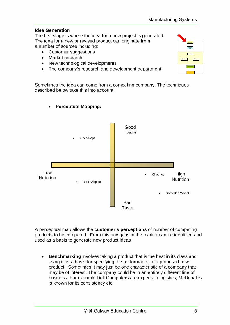
• Perceptual Mapping:
Low Nutrition
Good Taste
Bad Taste
High Nutrition
• Coco Pops
• Rice Krispies
• Cheerios
• Shredded Wheat
A perceptual map allows the customer’s perceptions of number of competing products to be compared. From this any gaps in the market can be identified and used as a basis to generate new product ideas
• Benchmarking involves taking a product that is the best in its class and using it as a basis for specifying the performance of a proposed new product. Sometimes it may just be one characteristic of a company that may be of interest. The company could be in an entirely different line of business. For example Dell Computers are experts in logistics, McDonalds is known for its consistency etc.
Manufacturing Systems
© t4 Galway Education Centre 5

• Reverse Engineering involves carefully dismantling and inspecting a competitor’s product to look for design features that can be incorporated into a new product. Ford used this technique in designing one new model where they copied BMW’s tyre and jack storage, Audi’s accelerator pedal and Toyota’s fuel-gauge accuracy among 300 other features.
Feasibility Study Once a promising idea has been identified the feasibility of it needs to be ascertained before investing money in its development. The cost of developing a new idea and commercialising it can run into millions of Euro so this is an important stage. The first stage is to conduct a market analysis. This involves carrying out customer surveys, interviews, or other market tests. The market analysis assesses whether there is enough demand for the proposed product to invest in developing it further. If a demand for the project exists, then an economic analysis is done. This takes the cost of developing the product and compares it to the estimated amount of sales. From this a price range for the product can be arrived at. There is a considerable amount of risk involved as data used in the analysis are far from certain.
Form Design
Functional Design
Production Design
Feasibility Study
Idea Generation
Pilot run and final tests
Product Launch
If the feasibility study gives a favourable outcome, a technical and strategic analysis can be made e.g. does the company have the technology/skills to make the product? Is it in line with the core strengths of the company (See earlier section on product positioning…) At the end of this process a product/performance specification is arrived at. This describes the function of the new product and what it should do to satisfy customer needs. Design of the Form and Function The next stage is to design the actual product. There are three aspects to this:
• Design of the Form of the Product This refers to the physical appearance of it – colour, shape size and style. This involves issues such as the Image of the product, market appeal and in many cases the functional design of the product must be adjusted to make the product look or feel right. For example a sports car manufacturer will spend time getting the exhaust note to sound right to fit in with the overall image of the car.
Form Design
Functional Design
Production Design
Feasibility Study
Idea Generation
Pilot run and final tests
Product Launch
• Design of the Function of the Product.
This refers to how the product will perform and how it will work – how well it meets the performance specification arrived at earlier. In and MP3 player, the storage capacity and audio/graphics capability would be examples of this.
Manufacturing Systems
6 © t4 Galway Education Centre

Production Design Once the form and function are specified the next stage is to design how the product will be made. This is an important stage in the process because designs that are difficult to make will often result in poor-quality products. As the design and manufacture stages are often separated in a company it is not uncommon for a design to go to manufacture and for the manufacturing people –who know the manufacturing processes better than the designers- to redesign parts of the product on the factory floor. These late changes are costly and difficult to implement. When designing for the production process two principles are useful:
1. Design Simplification This reduces the number of parts, assemblies and options in a product as well as avoiding fasteners, tools and adjustments wherever possible.
2. Design Standardisation
Using standardised parts that can be interchanged can simplify the process. One way of doing this is by having a modular design where standard building blocks or modules are combined in a variety of ways to create a unique finished product. Modular design is common in the electronics and motor industry. For example Dell Computers use a variety of standard modules (Hard Disk, Monitor, Memory etc) to build a PC. Toyota uses the same chassis for the Corolla, Camry and Lexus in America. Campbell’s use four basic broths: beef, chicken, tomato and seafood bisque which are produced in large volumes. They then add special ingredients to product the 125 varieties that appear in the shops. During this stage, a number of prototypes are built and tested.
Manufacturing Systems
© t4 Galway Education Centre 7

Pilot Testing After several refinements of the design a pilot run of the manufacturing process is conducted. Any adjustments are made before the final specification is agreed on. In this way the design specifications for the new product have considered how the product will be made.
Form Design
Functional Design
Production Design
Feasibility Study
Idea Generation
Pilot run and final tests
Product Launch
The final design consists of a detailed set of production drawings and specifications for the product.
Form Design
Functional Design
Production Design
Feasibility Study
Idea Generation
Pilot run and final tests
Product Launch
Once this is in place the product is ready to be launched. This involves ramping up the production and rolling out the marketing plans. Activity 1: Design of a hand held lamp (1) The picture below shows a part complete design for a hand held lamp. Do the following: 1. Name the people who would be involved in the design of the lamp 2. What tasks have been carried out to arrive at the point depicted in the image? 3. What are the remaining stages in the process of getting the product to the market? 4. Draw a flow diagram to show how the design information moves from the design department to the manufacturing department.
Manufacturing Systems
8 © t4 Galway Education Centre

Improving the Design Process The approach to design and manufacture described above is linear and sequential. There are a number of drawbacks to this approach including lack of communication between the people involved at the different stages of the process, designers not being aware of the issues that affect the product at the manufacturing stage, inefficiency when a design needs to be revised at a late stage in the process etc. The design process can be improved if the decision making process is revised so that all the participants work as a group as shown in the figure below.
A multi functional design team is put in place to replace the old linear process. Members of the team come from all parts of the design/manufacture spectrum. The characteristics of this approach are:
• Establish a multifunctional design team • Make design decisions concurrently rather than sequentially • Design for manufacture and assembly • Review designs to prevent failures and to ensure value • Design for the environment • Measure design quality • Use Quality Function Deployment • Engage in collaborative design.
These concepts are discussed in more detail below. Design Teams This approach has proved to be successful worldwide. A team would typically consist of people from marketing, engineering and manufacturing. Sometimes, customers, dealers and suppliers are involved as well. These are the so-called ‘create, make and market’ functions that inform the design and manufacturing process from the very beginning of the product development.
Manufacturing Systems
© t4 Galway Education Centre 9

Concurrent Design This is facilitated by the existence of the design team and helps to improve the quality of early design decisions and thereby reduce the length and cost of the design process. The design decisions overlap and the next stage of a design begins before the preceding one is complete. Concurrent design also involves the customer in the design process.
Activity 2: Design of a hand held lamp (2) Imagine that the lamp design team have decided to take a concurrent design approach. Do the following: 1. Name the people who would be involved in the design team. 2. What evidence is there that concurrent design is being used? 3. What tasks have been carried out to arrive at the point depicted in the image? 3. What are the remaining stages in the process to get the product to the market? 4. State what tasks will be conducted concurrently and explain how. 5. What technologies are used to facilitate this? 6. Draw a block diagram to show what processes are conducted in parallel. Indicate how the information is shared between them at each stage.
Activity 3: Imagine you are in charge of a design team who need to have a new design of mountain bike ready for the Christmas market. You want to use concurrent engineering to speed up the process and make it more efficient.
• Describe how your team will approach all the design tasks described earlier.
• Who do you need on the team? • What technologies do you need?
Think about the following areas:
• Concept design and idea generation • Prototypes and the form and function of the product • The feasibility of manufacture of your final design • Packaging, advertising (images and other material needed for promoting
the product prior to release).
Manufacturing Systems
10 © t4 Galway Education Centre

Design for Manufacture and Assembly This is the process of designing an artefact so that it can be produced easily and economically. It emphasises the importance of incorporating production design early in the design process. When successful it not only improves the overall product design but can reduce the time and cost of product design and manufacture. DFM guidelines are:
• Minimise the number of parts and sub-assemblies. Avoid tools, fasteners etc.
• Use Standard parts when possible and repeatable, well understood processes
• Design parts for more than one use and use modular designs • Design for ease of assembly, minimal handling. • Allow for easy testing and replacement of parts
Design for Assembly is a set of procedures for reducing the number of parts in an assembly and for reducing the number of assembly steps required. It is based on generic part shapes and their associated assembly times e.g. fitting a nut onto a bolt or snapping a cover onto a computer casing. Automated and manual assembly differ in this respect and there is a different approach for each. Activity 4: Take a familiar item such as a mobile phone or a household appliance or a computer. Identify one place where design for assembly has been used on the product. Reviewing Designs to Prevent Failures and to Ensure Value Before finalising a design, formal procedures for analysing possible failures and assessing the value of every part and component is performed. One technique used to do this is Value Analysis (VA). Value Analysis Value analysis tries to eliminate unnecessary failures and functions in a product design. The function of every part, material and operation that makes up the design is evaluated and the following questions asked of it:
• Can we do without it? • Does it do more than is required? • Does it cost more than it is worth? • Can something else do a better job? • Can it be made by a less costly method or a less costly material? • Can it be made cheaper, better, faster by someone else?
Manufacturing Systems
© t4 Galway Education Centre 11

Activity 5: Take the casing from the pond level project. Imagine that you want to produce the alarm in quantity for sale as part of a transition year business project. Conduct your own value analysis on the housing and come up with some recommendations on how it should be made and whether it should be bought in or made in the technology room. Use the internet to find real world suppliers of similar casings in your research. Look at the websites for Rapid Electronics, Maplin Electronics, Radionics and similar companies.
Manufacturing Systems
12 © t4 Galway Education Centre

Quality Function Deployment (QFD) QFD is a collection of matrices that converts the needs of the customer into technical specifications at all stages of the design and manufacture process. The most popular matrix is called the House of Quality.
1 2
3
4
5
6
Procedure:
1. Customer requirements prioritised (scale or %) 2. Competitive product evaluation 3. Engineering characteristics 4. Interrelationships of 1 & 3 5. Relations between engineering characteristics 6. Targets for new product
We will now apply this technique to the housing for the pond water alarm. The first thing we do is to find out what attributes are important to the potential users of the alarm. As part of the market research for the school based company, you make a survey a number of people in your area who have gardens. This is called the ‘Voice of the Customer’ and it gives the following table items and weightings
Wei
ghtin
g
Attribute Sensitive to water level 25Durable 15Makes a loud noise 10Inexpensive 25Small 10Looks Good 15
Total 100
Manufacturing Systems
© t4 Galway Education Centre 13
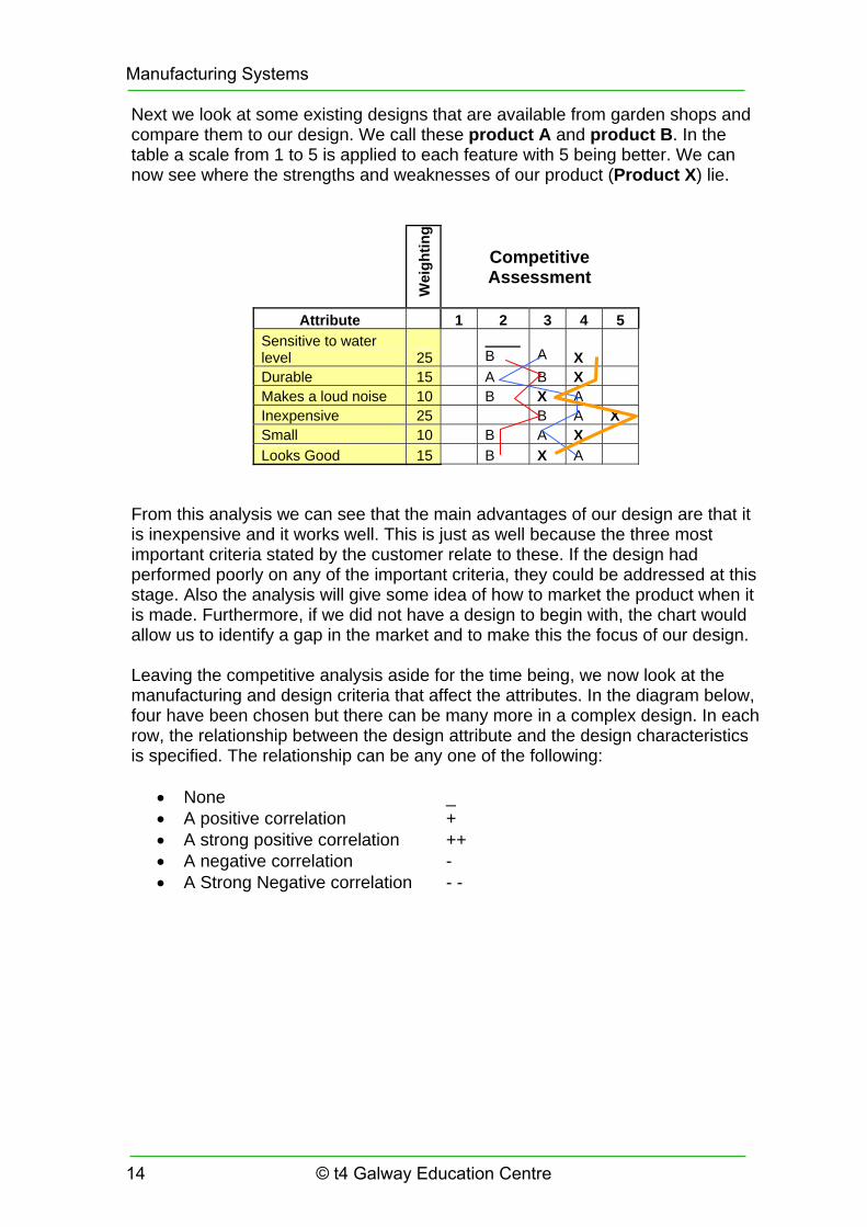
Next we look at some existing designs that are available from garden shops and compare them to our design. We call these product A and product B. In the table a scale from 1 to 5 is applied to each feature with 5 being better. We can now see where the strengths and weaknesses of our product (Product X) lie.
Wei
ghtin
g
Competitive Assessment
Attribute 1 2 3 4 5 Sensitive to water level 25
B
A X
Durable 15 A B X Makes a loud noise 10 B X A Inexpensive 25 B A X Small 10 B A X Looks Good 15 B X A
From this analysis we can see that the main advantages of our design are that it is inexpensive and it works well. This is just as well because the three most important criteria stated by the customer relate to these. If the design had performed poorly on any of the important criteria, they could be addressed at this stage. Also the analysis will give some idea of how to market the product when it is made. Furthermore, if we did not have a design to begin with, the chart would allow us to identify a gap in the market and to make this the focus of our design. Leaving the competitive analysis aside for the time being, we now look at the manufacturing and design criteria that affect the attributes. In the diagram below, four have been chosen but there can be many more in a complex design. In each row, the relationship between the design attribute and the design characteristics is specified. The relationship can be any one of the following:
• None _ • A positive correlation + • A strong positive correlation ++ • A negative correlation - • A Strong Negative correlation - -
Manufacturing Systems
14 © t4 Galway Education Centre

Wei
ghtin
g
Com
plex
ity o
f Circ
uit
Ener
gy E
ffici
ency
Mat
eria
l for
Cas
ing
Cos
t of S
enso
r
Attribute
Sensitive to water level 25 ++ + ++Durable 15 + Makes a loud noise 10 + - Inexpensive 25 -- + -- Small 10 - - Looks Good 15 +
Next we look at the design attributes themselves. There will often be a trade-off between one and another. We can look at this by constructing the roof of the house of quality
Com
plex
ity o
f Circ
uit
Ener
gy E
ffici
ency
Mat
eria
l for
Cas
ing
Cos
t of S
enso
r
+
+-
From this we can see that there are no major conflicts between the design considerations. A less complex circuit will, consume less power. A superior quality sensor (costs more) will be more energy efficient.
Manufacturing Systems
© t4 Galway Education Centre 15
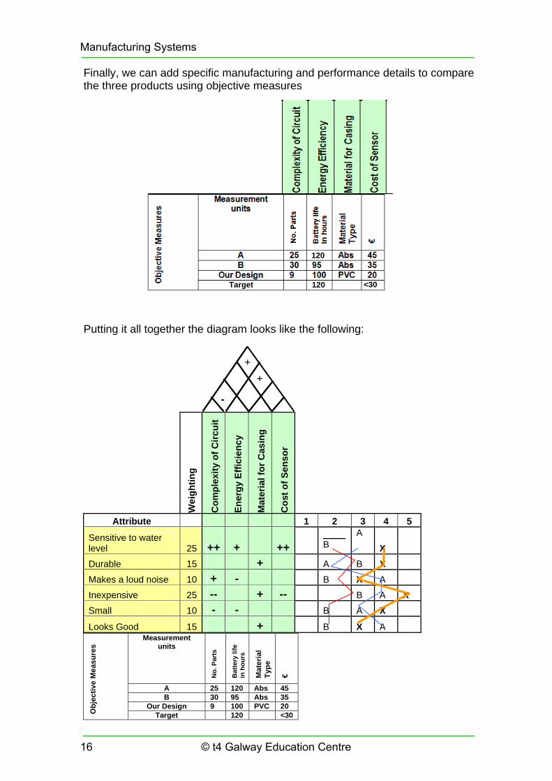
Finally, we can add specific manufacturing and performance details to compare the three products using objective measures
Target
120
120 <30
Putting it all together the diagram looks like the following:
Wei
ghtin
g
Com
plex
ity o
f Circ
uit
Ener
gy E
ffici
ency
Mat
eria
l for
Cas
ing
Cos
t of S
enso
r
Attribute 1 2 3 4 5
Sensitive to water level 25 ++ + ++
B
A
X
Durable 15 + A B X
Makes a loud noise 10 + - B X A
Inexpensive 25 -- + -- B A X Small 10 - - B A X
Looks Good 15 + B X A
Measurement units
No.
Par
ts
Bat
tery
life
in
hou
rs
Mat
eria
l Ty
pe
€
A 25 120 Abs 45 B 30 95 Abs 35
Our Design 9 100 PVC 20
Obj
ectiv
e M
easu
res
Target 120 <30
++
-
Manufacturing Systems
16 © t4 Galway Education Centre

The Role of Feature-based CAD in Design and Manufacturing of a Product In the last number of years, new products have become more common and product life cycles have become shorter. For example Sony introduced over 160 different models of Walkman during the 1990s. The ability to get new products to market quickly has revolutionised the competitive market and has changed the nature of manufacturing. One of the reasons behind this is the advancement of the technologies available for designing products.It begins with Computer Aided Design (CAD) and includes related technologies such as Computer Aided Manufacturing (CAM) and Computer Aided Engineering (CAE) CAD Modelling Modern CAD systems use feature based solid modelling to model the part or assembly being designed. Using this approach a part or design can be visualised and manipulated on a computer screen in a realistic manner. Assemblies can be made up from individual components and their function tested. Textures and lighting effects can be applied to the surface of the components to give photo-realistic effects. Manufacturing drawings can be generated automatically from the CAD model. However the biggest advantage is that once an item has been modelled in the CAD system, both the part and its manufacturing requirements can be shared with the entire design and manufacturing team. For example, the geometry from the CAD model can be used by the shop floor CAM system directly to produce the part. It can be used by the marketing team to generate images for the packaging (even though the item has not been manufactured yet). It can be used to simulate the behaviour of the product under the stresses and forces it may experience in use by importing it to a CAE system and conducting a finite element analysis on it. Rapid prototyping machines can be used to ‘grow’ a prototype part from plastic in a short time and this can be used to evaluate the ‘look and feel’ of the product. As all of these functions take data from the same CAD model, all can be conducted concurrently. This means that any or all of the manufacturing problems can be seen at an early stage. Any changes in the design can be seen by all concerned immediately. This greatly assists in speeding up the design and prototyping process. In the school, SolidWorks can be used to design a three dimensional model and assembly. It is possible to animate the workings of assemblies and to generate working drawings directly from them. The design itself can be machined in a short time on soft material such as modelling foam using a desktop router. Alternatively two dimensional parts can be laser-cut if required.
Manufacturing Systems
© t4 Galway Education Centre 17

Activity 6: Think about the CAD/CAM systems available in the Technology room. How much of the above is it possible to use in a school based design project? Consider the following areas:
• Design of form/function • Prototyping • Production of working drawings • Manufacturing of mechanisms/linkages etc • Finishing e.g. logos etc
Testing and Product Design The previous sections showed how the design of the product takes into account the needs of the user, the form and function of the item itself and its impact on the environment. In each of these areas there is design intent. However good the judgement of the design team might be, it is not possible to predict with absolute confidence how the item will perform in practice. Therefore it is necessary to carefully test the product before it is put into mass production. Remember that mass production is usually very expensive to set up and cannot be changed easily once in place. Usually a set of prototypes are made up and used for testing. Prototypes are usually made individually or in small batches using conventional (i.e. non mass-production) equipment. Tests can be as simple as investigating whether the product meets its performance specifications. In other cases the expected life of the product may be of interest. Sometimes it is useful to know the means by which the product is likely to fail. These three scenarios are now considered. Testing a Design or Product for Performance Specifications Consider again our pond alarm project.
Some of the design characteristics we identified were that it should be sensitive to the water level and that it should be durable.
Manufacturing Systems
18 © t4 Galway Education Centre

We might set up a series of tests as follows: Test Procedure Minimum
performance Result
Casing Seal
Submerge in water for 8 hours Remove, Dry, disassemble and inspect
No evidence of water ingress
Sensitivity of sensor
Submerge probes to 8mm in sample of pond water Retract
Alarm should trigger before 8mm is reached Alarm should reset within 1 min
Battery life Trigger alarm and measure time until battery depletes.
Alarm should sound for 1 hour minimum
Ability to withstand extreme weather
Place in freezer at -15°C and in oven at 50°C for 1 hour
No damage should be apparent to casing or function
Alarm Volume Trigger in an unobstructed area then move away until alarm is no longer audible
Should be audible up to 30m
There are more tests that could be carried out to establish other characteristics of the design. For example, the how the alarm reacts to corrosion of the probes might be of interest. However this would normally take a long time to develop – it might be possible to dip the probes into a corrosive substance (e.g. a dilute acid) to accelerate the process. A similar approach might be taken with the housing to estimate how long it might survive in use. This type of testing is called accelerated testing. It is widely used where products are expected or required to last for a given lifetime. Two types of accelerated testing are described in the next section. Activity 7: Take any project you have completed in the Technology class and devise a set of tests that will determine how well it meets the design criteria you set out for it. If you have completed a design folio, these will be the set of criteria you set out at the end of the analysis phase of your work.
Manufacturing Systems
© t4 Galway Education Centre 19

Activity 8: Testing is an important part of validating a design. If the product tests successfully what does it tell you about your design? Think about what you might do if the product fails any of the tests. How will it affect the design? Activity 9: Take a familiar product (such as a wristwatch) and do the following:
• Choose two criteria that you think the design should meet. • Devise two tests to measure them.
The Role of Accelerated Testing for Simple Products A designer may need information about the expected life of a design in order to estimate its reliability. As it is not possible to test all products, a sample (or prototype) is usually taken and the tests are conducted on these. Where the expected life of the product is long it is usual to conduct accelerated tests to capture the life data for the product. These tests cause the product to fail in the same manner as when in normal use but in a much shorter time. Performed correctly, accelerated testing can significantly reduce test times, resulting in reduced time to market, lower product development costs and lower warranty costs, as well as other benefits.
There are a variety of types of accelerated testing approaches and the accelerated testing strategy must be carefully designed to fit the product under consideration
Qualitative Accelerated Tests Accelerated testing methods can be either qualitative or quantitative. Qualitative accelerated tests (sometimes called “torture tests” or “shake and bake” tests) are used primarily to reveal probable failure modes for the product so that engineers can improve the product design. These tests are performed on small samples with the test units subjected to a single severe level of stress (e.g. stress cycling, cold to hot, etc.). If the specimen survives, it passes the test. Otherwise, appropriate actions will be taken to improve the product’s design in order to eliminate the cause(s) of failure that were identified during the test.
A good qualitative accelerated test quickly reveals the failure modes that will occur under normal use conditions but does not introduce failure modes that will never be encountered in real life situations. These tests can provide valuable information about the types of stresses and the stress levels that should be applied in subsequent quantitative accelerated life testing. However, in general, they do not provide information that can be used to quantify the life characteristics of the product under normal use conditions.
Manufacturing Systems
20 © t4 Galway Education Centre

Quantitative Accelerated Life Tests Quantitative accelerated life tests on the other hand, are designed to quantify the life of the product and to produce the data required for accelerated life data analysis. This type of test involves the controlled application of accelerated stress conditions in order to stimulate product failure and provide life data more quickly. The life data obtained from these tests can be used to estimate reliability of the product
QALT tests can employ usage rate acceleration or overstress acceleration to speed up the times-to-failure for the products under test. With usage rate acceleration, which is appropriate for products that do not operate continuously under normal conditions, the analyst operates the products under test at a greater rate than normal to simulate longer periods of operation under normal conditions. For example, if an appliance manufacturer assumes that the average washing machine will be used about six hours per week, then the manufacturer can test a sample of products continuously to reduce the test time by a factor of 28. With this testing approach, one week of continuous testing can be used to simulate 28 weeks of operation under normal use conditions.
However, this testing method is not effective for products that have a very high or continuous usage rate under normal conditions. Some electronic devices, for example, are expected to operate continuously under normal use conditions. Usage rate acceleration is not an option for this type of product and a different type of accelerated life test must be used in order to obtain data for these products quickly. In these cases, overstress acceleration is used instead. With overstress acceleration, one or more environmental factors that are known to cause the product to fail under normal conditions (such as temperature, voltage, humidity, etc.) are increased in order to stimulate the product to fail more quickly during the test. The stress types and stress levels used in overstress acceleration tests must be carefully chosen so that they accelerate the failure modes for the product but do not introduce failure modes that would never occur under normal use conditions. Normally, these stress levels will fall outside the product specification limits but inside the design limits. The data from this type of test require special accelerated life data analysis techniques, which include a mathematical model to “translate” the overstress data back into normal usage.
Manufacturing Systems
© t4 Galway Education Centre 21

Example: A designer wants to make a washing machine that will last for ten years in normal use. It is expected that a typical household will use the machine three times a week for a wash cycle that will last for 2 hours on average. A prototype machine has been made and needs to be tested. What type of test should be used? How long must the machine survive during the test? Answer: The total hours life required for the machine is: 2 hours/wash x 3 washes/week x 52 weeks/year x 10 years = 3120 hours Use a quantitative accelerated test. Run the machine constantly for 3120 hours. Activity 10: You have a task of choosing a 6v light bulb for a project. You have a choice of three bulbs, each from a different manufacturer. You want to choose the bulb that is likely to last the longest in normal use. Devise an accelerated test to identify the most suitable bulb. Assume you have access to a variable voltage power supply Activity 11: Consider an office chair. These chairs wear out from repeated loading from people sitting down on them and getting up again. Try to estimate the number of times a person might sit on an average chair in your classroom. Assume a test rig is available that can apply a load to the chair that is equivalent to a person sitting on it once every ten seconds. How long must the chair be tested to give an equivalent life of ten years?
Manufacturing Systems
22 © t4 Galway Education Centre

Design for the Environment (DfE) Each year millions of home and office appliances, computers and vehicles are disposed of. This has prompted governments and industry to consider the environmental impact of the product design. Design for Environment involves designing products from recycled material, using materials or components that can be recycled, designing a product so that it is easier to repair than discard and minimising unnecessary packaging. As shown in the figure it also includes minimising the energy used during manufacture, consumption and disposal.
There are three major elements of design for the environment:
• Design for environmental manufacturing, • Design for environmental packaging, and • Design for disposal and recycling.
Design for environmental manufacturing involves the following considerations: • Non-toxic processes & production materials • Minimum energy utilization • Minimize emissions • Minimize waste, scrap & by-products
Design for environmental packaging involves the following considerations: • Minimum of packaging materials • Reusable pallets and packaging • Recyclable packaging materials • Bio-degradable packaging materials
Manufacturing Systems
© t4 Galway Education Centre 23

Activity 12: Examine the packaging that comes with a new computer or new household appliance.
Is all of it necessary? What materials are used? Are they recyclable? Do they make use of recycled materials themselves? Can you make a suggestion for improvement?
Design for disposal & recycling involves the following considerations:
• Re-use / refurbishment of components & assemblies • Material selection to enable re-use (e.g., thermoset plastics vs.
thermoplastics) and minimize toxicity • Avoids filler material in plastics such as fibreglass and graphite • Minimum number of materials / colours to facilitate separating materials
and re-use • Material identification to facilitate re-use • Design to enable materials to be easily separated • Design for disassembly (e.g., fracture points, fastening vs. bonding) • Avoid use of adhesives • Limit contaminants - additives, coatings, metal plating of plastics, etc. • Maximize use of recycled or ground material with virgin material • Design for serviceability to minimize disposal of non-working products
Activity 13: Take a household appliance and try to identify as many of the ideas listed above in its manufacture and design. To support design for recycling, design for disassembly needs to be addressed. Design for disassembly enhances maintainability or serviceability of a product, and it enables recycling of materials, component parts, assemblies, and modules. There are a number of principles to facilitate disassembly:
• Provide ready access to parts, fasteners, etc. to support disassembly. • Design modular products to enable modules to be disassembled for
service or re-use. • Minimize weight of individual parts and modules to facilitate disassembly. • Use joining and fastening techniques to facilitate disassembly (e.g.,
fasteners instead of adhesives) • Minimize fragile parts and leads to enable re-use and re-assembly. • Use connectors instead of hard-wired connections. • Design to enable use of common hand tools for disassembly.
Activity 14: Examine a desktop computer or monitor and identify two features on it that allow easy disassembly
Manufacturing Systems
24 © t4 Galway Education Centre

In the EU car manufacturers are required to pay for the recycling of all cars made after 2001 and a Product Recycling Fund applies to all consumer electronic items purchased new. The fee is based on the size of the item and varies from less than one Euro for small items such as hairdryers and increases to ten euro or more for large items such as televisions, cookers and refrigerators. The consumer pays the fee when purchasing a new item and it entitles them to return it for recycling when its life is over. Activity 15: Visit a hardware or electrical shop and find out how much the PRF costs for:
• A hairdryer or similar item • A cooker or fridge • A microwave oven • A mobile phone or MP3 player
The Impact of Product Life Cycle on the Environment The section on Design for the Environment dealt with ways to minimise the negative impact on the environment that a product might have. In this section, we will look at how these ideas might be incorporated into the design of a simple product. Here, we take the product life cycle to mean the design, manufacture, use and disposal stages of a typical product. At each of these stages, it is possible to incorporate, recycling, re-use and waste strategies into the product specification. Case study 1: Desktop computer Design Stage: The design could specify the following Reusable components e.g. monitor, keyboard Recycled materials where possible Minimise toxic materials used Manufacture: Use ethical work practices and sources for raw materials Use ‘clean’ manufacturing processes Minimise transport of components and materials Implement quality procedures to minimise waste etc. Use: Low power consumption Serviceable items rather than replaceable e.g. disk drive, peripherals etc. Disposal: Design for disassembly – use easily dismantled fixings etc. Identify materials used for recycling Minimise mixed materials to facilitate separation later
Manufacturing Systems
© t4 Galway Education Centre 25

Case study 2: Milk Carton Design: Look at designs that minimise the use of raw material per unit volume Avoid designs that use more than one material if possible (e.g. plastic cap on paper carton) Manufacture: Minimise material waste during printing and folding of carton Specify recyclable paper. Minimise toxic inks and coatings on outside Use: Allow resealing of carton to prevent spoiling of contents Disposal: Design to allow easy crushing or compacting of carton to facilitate recycling Make carton easy to rinse to facilitate recycling Activity 16: Take the following products and try to analyse them in a similar manner:
1. Hand held flashlight 2. Electric fan heater 3. Mobile phone handset 4. Electric light bulb 5. Metal drink can
Manufacturing Systems
26 © t4 Galway Education Centre

Manufacturing System Design and Control Facility Layout and Work Flow Facility layout refers to the arrangement of machines, departments, workstations, storage areas, aisles and common areas within a factory. The objective of facility layout decisions is to ensure a smooth flow of work, material, people and information through the system. When thinking about the following section, keep in mind the ideas from the product process matrix that were discussed earlier. There are three basic types of layout:
• Process • Product • Fixed-Position
And three hybrid layouts:
• Cellular • Flexible Manufacturing Systems • Mixed-model Assembly Lines
Process Layouts group together similar activities according to the process they perform. An example would be to locate all the drills together in one area of a workshop and lathes in another. In a department store, women’s clothes, men’s clothes and children’s clothes are located in separate departments. This is suitable for low volume or batch production where there is variation between the jobs or customers. This layout is flexible but not as efficient due to the generalised nature of it.
Lathe Department
Milling Department Drilling Department
Grinding D t t
Painting Department
Receiving and Assembly
L L
L L
L
L
L
L
M M M
G G G G
D D D D
D D D D
P P
A A A
Manufacturing Systems
© t4 Galway Education Centre 27

Product layouts are better known as assembly lines and they arrange the activities in a line according to the sequence of operations needed to make a particular product. The line is set up for one particular product and specialised machines are often used. This type of layout is efficient but not flexible.
IN
OUT
Fixed position layouts are used for projects in which the product is too big or heavy to move such as the construction of an Aircraft. These are usually specialised to the project involved. Equipment and parts are moved in and out of the work area as required. Hybrid Layouts Cellular layouts attempt to combine the flexibility of the process layout with the efficiency of the product layout. Machines are grouped into cells that process families of parts with similar shapes (or more accurately, similar features e.g. bored hole, threading operation etc.). Group Technology is a system that is used to classify parts within a family and identify similar characteristics or operations that need to be carried out on it.
The family of parts shown above have the same features but differ in size and number of them. However the processes and machinery used to manufacture
Manufacturing Systems
28 © t4 Galway Education Centre

them will be similar. This means that a work cell can be set up to process them. A work cell resembles a small assembly line i.e. a product layout. The layout between the cells is treated as a process layout. Design of a work cell Consider a process-based layout shown below. Three products are produced and the route of each one through the individual machines that make up the workshop are shown below.
4 6
5
1
2
11
9
8
7
12 10
3
Raw Materials
Assembly
Notice the distance that each part must travel and the irregularity of the part routings. By examining the route of each part through the process, it is possible to come up with a more efficient arrangement for the machines. In this case they can be rearranged into three cells as shown below:
4
6
51
2 11
98
7
12 10
3
Raw Materials
Assembly
Manufacturing Systems
© t4 Galway Education Centre 29

The process paths are identical but the order is more logical and transit time, setup time and inventory are reduced since similar parts are produced together in each cell and the distance from machine to machine is reduced. It is possible to design the layout of each cell so that each worker has easy access to more than one machine as it is usual for workers to be able to operate more than one machine. A U-Shaped layout is common such as that shown in cells 1 and 3 above. Cells are designed with the path the worker will take between the machines in mind. A typical U-Shaped layout is shown below:
Activity 17: For each of the scenarios below, decide what processes are involved. Draw a flowchart to show how they interact with one another and devise a cellular layout to optimise each one. 1. Family kitchen 2. Fast food outlet serving the usual variety of items 3. Airport passenger terminal departures area with ticket issue, automated check-in, shopping, restaurant and security control for boarding. 4. Technology room
Manufacturing Systems
30 © t4 Galway Education Centre

Automated Manufacturing Cells The design of cells lends itself to automation. Automation is expensive and it is uncommon for a company to automate an entire factory at one time. Cellular layouts can be automated one cell at a time. The figure below shows a manufacturing cell consisting of a CNC lathe, Milling machine and Grinder being tended by a robot. The raw material and finished parts arrive and leave by a conveyor.
Flexible Manufacturing Systems. The idea of the flexible manufacturing system is an ambitious one. It involves automating the entire manufacture of a product or family of products. The system controls the entire flow of work between individual machines. Conveyors, automatically guided vehicles and robots are used to load, unload and transfer the work from station to station. The software used to control the system is very complex and the entire system is typically very expensive. There are very few (less than 400) full size flexible manufacturing systems in use worldwide due to their cost and complexity. A much more common approach is to base the system on a Flexible Manufacturing Cell which is a much smaller version of the FMS. A flexible manufacturing cell can be as simple as two CNC machines and a robot. Two or more flexible manufacturing cells are usually considered to be a FMS. Each cell will make a family of parts as described earlier. The ideas of Group Technology are very important and form the basis of how much of the work is organised within the cell. It is usual to have more than one job in progress at any given time with each particular item following its own path through the cells. The routing of the parts within and between the cells is controlled by software that organises the transport of the part and the sequencing of the operations carried out on the part.
Manufacturing Systems
© t4 Galway Education Centre 31

There are a number of possibilities for the layout of the cells within a FMS of this type. Some possibilities are shown below.
Progressive FMS
Load Station Unload Station Pallet
In a progressive FMS like that shown above, all the parts follow the same progression through the machinery. This approach works best where group technology can be easily applied to the parts being made. i.e. they fall into well defined families.
Closed Loop FMS
Pallet
Unload Load
In the closed loop FMS shown above, the parts can each follow different paths and the cell can allow for a greater variety of parts than the progressive cell. Parts can visit stations in alternative orders and can skip stations if they are not required. A third type of layout is the ladder layout. This is so called because the machines appear to be located on the steps of a ladder. This offers more
Manufacturing Systems
32 © t4 Galway Education Centre

flexibility than the two types of cell described previously. Parts can be routed to and from any machine in any sequence as the path layout allows greater flexibility in routing.
Ladder FMS layout
Load/Unload
Activity 18: Look at the composite photograph of a FMS cell below. Try to identify as many parts of the cell as you can.
Picture: www.majortool.com
Manufacturing Systems
© t4 Galway Education Centre 33

Activity 19: Use the internet to research how companies use FMS cells to manufacture products. It might be helpful to search for images at first to locate the most useful sites. Try the following site as a starting point. http://www.mapromec.fi/document.aspx?docID=413 Mixed Model Assembly Lines The traditional approach to assembly lines is to have one setup for a particular product. This is run for a set time and then the line is shut down for a changeover to another type of product. The problems with this type of approach have been explained earlier in the section on JIT – changeovers cause a loss in production and cost money to perform. Long runs of one product mean inflexibility in response to customer demand etc. A Mixed Model Assembly Line is one way of overcoming this problem. In mixed model assembly lines more than one type of product is processed by the line during a run. This is achieved by the following means. First, changeover time is reduced to a minimum by standardising equipment and procedures. Second, the workers are trained to work on more than one workstation at a time. This allows them to help one another if necessary. Thirdly, the layout of the lines is changed to allow the workers to assist one another as needed. This also allows increased efficiency as shown in the diagram below.
Straight line traditional layout. In this arrangement station 3 will need to wait nine minutes until the next part comes along.
A B C
9 min 12 min 3 min
A
B
C
9 min
12 min 3 min
U Shaped line for mixed model assembly. Operators share the tasks at A and C. This means no wasted time as both stations take 12 mins total time.
Finally, the order of the products through the line is chosen so that the individual differences between long and short operations cancel one another out as much as possible. For example a model that had a long drilling operation might be followed by another with a short drilling operation.
Manufacturing Systems
34 © t4 Galway Education Centre

Consider the fast-food restaurant example from earlier. At present the food is prepared as follows. a) Employee 1 Cook Burger buns 6 mins b) Employee 2 Cook Fries 5 mins c) Employee 2 Pack Fries 1 minute d) Employee 1 Assemble Burger 2 min Minimum time for Burger and Fries is 8 minutes This can be considered as a mixed model assembly process where the fries represent one model and the burger another. They share some characteristics in common e.g. how they are cooked but there are obvious differences also. The assembly process for a food order looks like the following:
A&B 6 Mins
C&D 2 min
Total time 8 min
Alternative layout Total time 7 min
A&B 6 Mins
C 1 min
D 2 min
By retraining the employee at D (Assembling the burger) to share the task of cooking, (A and B) the process can be made more efficient.
Manufacturing Systems
© t4 Galway Education Centre 35

Capacity Management The demand for a product or service produced by a firm can fluctuate over time. It is very important that an economical means of meeting the demand is devised. If a firm does not have enough capacity to meet an increase in demand it will likely lose business from not being able to supply its product or service. On the other hand if there is excess capacity it will be uneconomical and will result in losses from maintaining unused resources, labour etc. Capacity planning is used to establish the overall level of productive resources for a firm and to try to match it to present and anticipated levels of demand. When to increase capacity and How much to increase capacity are two key decisions in this regard. When to increase capacity? There are three basic strategies for timing of capacity expansions.
• Capacity Lead Strategy – capacity is expanded in anticipation of expected growth. This is often done by new businesses expecting to gain custom from their competitors. e.g. building a new shopping centre with shops, parking etc.
• Capacity Lag Strategy – capacity is increased after an increase in demand has been documented. This is common where competition is weak and there is an assumption that lost customers will return once the capacity has been expanded.
• Average Capacity Strategy – capacity is expanded to coincide with the average expected demand. This is done usually where there is an expectation that some of the additional output will be used or sold.
The figure below shows the different strategies: Lead Capacity
Demand
Capacity
Quantity
Time
Manufacturing Systems
36 © t4 Galway Education Centre

Lag Capacity
Demand
Capacity
Time
Quantity
Average Capacity
Demand
Capacity
Quantity
Time
Manufacturing Systems
© t4 Galway Education Centre 37

How much to increase capacity?
apacity and how certain the increase in emand will be as well as other factors.
a t efficient
ay to work as mistakes tend to be made and things will go wrong.
. Sometimes a negative cushion is used – Airlines ommonly allow overbooking.
ust in Time Manufacturing (JIT)
s
obsolete
s
are
er by
ea where they are customised, boxed and sent to
aiting delivery trucks.
pliers
re
. t the parts ordered from it are available
minutes to deliver em to the plant.
This depends on the cost of increasing cd The optimum level of capacity is when the unit cost for operation is lowest. This might be the running cost per room in a hotel or the production cost per item in manufacturing plant. Operating at 100% of capacity is rarely the mosw Often a capacity cushion of 20 % is used where there is 20% spare capacity to allow for unexpected demandsc J Modern products have shortened life cycles, and there is much pressure on manufacturers for a quick response to the customer. One way of ensuring aquick turnaround time is to hold an inventory of stock items to that they are available when they are needed. However holding these items costs money athey need to be bought and stored prior to use. In a climate of rapid product change, there is a possibility that the inventory items may becomebefore they are used, therefore increasing the cost even further. A better approach is to make the production process leaner and more agile. If the suppliers are coordinated with the manufacturing company then it is possible to implement what is known as Just in Time manufacturing. Dell Computers useJIT at their manufacturing plants around the world. A typical Dell plant allocatejust a tiny part of its floor area for incoming parts. In one plant that has a floor area the size of 23 football fields, the incoming parts area is just 3metres squ– the size of a bedroom in an average house. A plant will assemble tens of thousands of computers each day. Computer controlled conveyors move the parts quickly through the plant where components are added to the computer. Drives, chips and other components are added according to customer ordworkers who respond to red or green lights on component drawers. The assembly process takes three or four minutes after which the computers aremoved to the finishing arw How it works Online orders are downloaded to a factory planning system which generates a production schedule every two hours for the plant. The system notifies supof Dell’s exact material needs and works out schedule for assembling the machines depending on the availability of the materials. As the machines abeing built, the parts needed for the next two-hour set of orders are being shipped from supplier hubs. These are mini-warehouses that are maintained by the suppliers and contain two weeks worth of components near the Dell factoryThe hub has 15 minutes to confirm thaand 1 hour and 15 th
Manufacturing Systems
38 © t4 Galway Education Centre

Issues such as quality of the supplied parts must be guaranteed if JIT is to work. Therefore quality systems must be in place before a supplier is accepted by a large manufacturer such as Dell. Concepts such as six-sigma described earlier allow the quality of the supplied parts to be guaranteed. JIT originated in Toyota in the 1950s and is more than just a means for reducing inventory. To work properly, the entire production process must be streamlined and efficient. The underlying concept is ‘eliminate waste’ This means eliminating anything other than the minimum amount of materials, parts, space, tools or time than is essential. While the idea is simple it is difficult to put into practice. Where there are a number of stages or processes in manufacturing a product, each must be carefully set up so that the amount of time, materials etc required are known and controlled. Quality must be carefully controlled at each stage as one defective component will affect all the subsequent stages. For example, one late delivery or a batch containing a faulty keyboard would have a significant effect on the computer assembly process described above. Another important concept is that that the volume of items being made should be more or less steady, even if they are of different type. This allows the production processes to be optimised and synchronized. For example, a car manufacturer may produce 2000 cars per week but these may be of different type and model, e.g. passenger car may be followed on the assembly line by a SUV and then by a van etc, according to the customer orders for that week. The upstream processes that make the drivetrains and bodywork produce these at a constant and predictable rate. As the processes involved are standardised, each can make one of a family of parts e.g. engines without any need to stop or change the setup. Once made, each individual item joins the assembly line at the correct place and just when it is needed for assembly. This means the assembly process can be more flexible. Compare this to a system where all vans are made at the start of the month followed by a changeover to making cars and then SUVs etc. In this case a SUV ordered at the start of the month would not be ready until some weeks later. Production time would be lost due to the time spent changing the tooling to a different model. On the other hand the JIT process would be able to make any type of vehicle in any order at any time – the benefits of this are obvious. Activity 20: Look at one large fast food restaurant that you are familiar with. Consider the following questions. 1. How steady is the volume of trade 2. How standardised are their products – are there common items for example in different types of burger 3. How standardised is the production process for them. Does the production time vary for any given item? 4. Look at the process of making e.g. a burger in reverse from the point of order. What steps are involved in manufacture? How many items are stored between each stage of the process?
Manufacturing Systems
© t4 Galway Education Centre 39

One big problem for JIT systems is to control the flow of product through the factd4ory. You will have noticed from the previous example that it is difficult to decide exactly when to start making a batch of fries or when to start frying a burger or how many to cook at a time. If too many are made they will deteriorate and too few will mean customers will be kept waiting. Consider the following scenario: On a busy Saturday night, sixty portions of fries are sold every hour. Fries take five minutes to cook and each batch holds five servings. The optimum situation would be as follows: To begin, the counter staff, start with five servings ready to go. They immediately order another batch and begin to sell the fries they have. By the time they run out (i.e. after five minutes) the batch is ready. They take these and order another batch etc. The advantages of this system are obvious. There are always just enough fries to serve the customers. They are always freshly cooked and warm. There isn’t any wasted material. This system is called a PULL system – production of the item is governed by demand for the finished item, this in turn ‘pulls’ items from upstream in the production process. For example, a bucket of raw fries might hold 200 servings and needs to be held in a cold room. How often should the frying station request the raw fries? Furthermore, the supplier of the fries delivers in batches of five buckets at a time. They deliver daily – what quantity should be ordered and when?
Manufacturing Systems
40 © t4 Galway Education Centre
Activity 21: This system works well because the demand and the process time are constant. Towards the end of the night, custom slows down and the demand drops to one portion of fries every five minutes – describe the problems this will cause for the JIT system The scenario above is a simple one. Imagine the complexity where an item such as a car is being built with dozens of sub assemblies, each in turn consisting of hundreds of components. All of the components need to be manufactured just in time. Regulating the flow of the components is one major problem as we have just seen. (The issues of standardisation, quality etc described earlier are others) One widely used system for controlling flow of product is the Kanban system. Kanban Systems: Kanban is the Japanese word for card. Kanbans are used in JIT as part of a ‘pull’ system that is used to regulate flow of the materials and component parts through the manufacturing system. A major problem in assembling a complex item is the coordination of the parts and sub-assemblies as they move along the production line. With a car, these amount to dozens of sub-assemblies consisting of thousands of components. Taiichi Ohno who worked with Toyota got inspiration for the idea when visiting a supermarket when in America. He observed that most Americans did not keep large stocks of food at home. Instead, they visited the nearby supermarkets to purchase items as they needed them. The supermarkets in turn fully control their inventory by replenishing items on their own shelves only as they are removed. Customers actually ‘pull through’ the items they need and supermarkets only order as much as they can sell. Applying this concept to the manufacturing system, each stage of the process requests parts/assemblies from the preceding stations only as they need them. This is in contrast to the traditional ‘push’ model where one station would complete its work and pass it on to the next whether it was needed or not. With a ‘pull’ system the operations are forced to work in coordination with one another. To regulate the flow of materials, Ohno introduced kanbans in the Toyota plant. Kanbans are a very simple concept. A Kanban contains a basic description of the part required, the number required, and other information about the part. Kanbans are used like order forms for components and are passed from one station to another to initiate the production or movement of parts within the manufacturing plant. Kanbans are often attached to boxes or containers that are used to transport the items concerned. In the example above from a car manufacturing plant, the container holds four air flow meter assemblies. The container will arrive containing the four items and the kanban card. The card is immediately sent back to reorder another lot of airflow meters. By the time they arrive, the last of the original four meters will have been used. The new four meters are accepted and
Manufacturing Systems
© t4 Galway Education Centre 41

the kanban reissued again – see the similarities with the fries example given previously. Obviously, the production process must be in a steady state i.e. fixed rate production and each of the sub processes involved must be understood and controlled thoroughly. Remember the problem solving tools for quality in the core section. Looking at the card itself, the information contained is as follows:
• The quantity of items in the container • The part number and description • The address at the top left states where the full container is to be
delivered • The address on the top right corner specifies where the empty container is
to be picked up • The lower left corner states the preceding process. (The sub-contract
supplier in this case) • Finally, the bottom right corner specifies the subsequent process (N2)
The card is bar-coded to speed up reading the information and to eliminate error. Activity 22: Design a Kanban system for the fast food restaurant in the previous example. Concentrate on the fries only. There should be one card for each stage in the process.
Manufacturing Systems
42 © t4 Galway Education Centre
Related Documents