LE750 Instruction Manual

Welcome message from author
This document is posted to help you gain knowledge. Please leave a comment to let me know what you think about it! Share it to your friends and learn new things together.
Transcript

LE750Instruction
Manual
Page - 1
LE750 - Rotary Cutter Controller designed and developed byLyons Electronics.
Lyons Electronics2 Grange GardensCAMPTON NR. SHEFFORDBedfordshireUnited KingdomSG17 5PD
Telephone: Hitchin (01462) 811888Facsimile: Hitchin (01462) 811898
Lyons Electronics has now been established for over 16 years. During that period we have been concentratingmainly on electronic control systems for the Plastics Extrusion Industry.
Units manufactured by Lyons Electronics include Rotary Cutter Controllers, High Speed Switches forcontrolling Vacuum, Pneumatic and Electromagnetic Clutches, Microprocessor Bubble Tubing controllers,Sequencers for synchronising complex lines, and Guillotine and Saw controllers.
All of our electronic controllers have been designed to achieve the highest accuracy's available from theequipment in which they have been installed and to be robust and reliable.
LE750 Instruction Manual
While every precaution has been taken to ensure that the information contained in this package is correct, noresponsibility for errors or omissions is assumed.
No part of this publication may be reproduced, stored in a retrieval system, or transmitted in any form, or by anymeans, electronic or otherwise, without the prior specific written permission of Lyons Electronics. The onlyexceptions are for the purpose of private or study use.

Page - 2
LE750 Features
* Light touch-sensitive membrane panel
* Bright clear displays for easy readability
* Rotary cutter control
* Feed or Take-off control
* Automatic or Manual Batch Sorting
* 4 Lengths available with associated batches and outputs
* 4 different cutting modes plus an option for special applications
* 2 Tachometers to show Blade revolutions per minute and line speed in metres or feet per minute
* 2 x 10 decade total counters
* Ten year memory retention
* Automatic self-testing
* System testing for engineers
* Synchronising to and from external controls possible
* Dimensions - 250mm wide x 100mm high x 170mm deep.(250mm deep with connectors attached)Panel cut-out 225mm x 95mmFixing Dimensions 235mm x 60mm

Page - 3
Contents
Section 1
Introduction........................................................................................5
Section 2
Power-up Condition............................................................................6
Section 3
Panel Controls ....................................................................................7Start / Stop..........................................................................................7Auxiliary On / Off ..............................................................................7Cut Mode ...........................................................................................7
Timer .........................................................................................7Counter ......................................................................................7End Sense...................................................................................8Continuous .................................................................................8Option........................................................................................8
Alarm Reset........................................................................................8Sample Cut.........................................................................................8Total En / Dis .....................................................................................8Run Order ..........................................................................................9Prog / Enter ........................................................................................9Length, Batch, Delay, Timers..............................................................9Total10Tacho ...............................................................................................10Batch Count......................................................................................11Clear ................................................................................................11Sounder ............................................................................................11
Section 4
Panel Control Programming..............................................................12Preset Limits and Ranges ..................................................................18
Section 5
Unusual Key Combinations ..............................................................19Total 1 Reset ....................................................................................19Select Next Length in Run Order ......................................................19Length Programming (Trimming) .....................................................19

Page - 4
Section 6
Single Length Setting........................................................................20Dual Length Setting (Flip-flop) .........................................................20
Section 7
Programming Timers (Output Triggering).........................................21Re-triggering Parameters ..................................................................21Example - Batch Sorting using Timer 1 only .....................................21Example - Batch Sorting using both Timers.......................................22Automatic Batch Sorting...................................................................22Manual Batch Sorting .......................................................................22Automatic Power Down....................................................................23Complete Internal System Block Diagram.........................................23Setting Tachometer Sample Timers...................................................24Typical Tachometer Sample Timer Settings ......................................25
Section 8
External Programming Unit ..............................................................27Test Procedures ................................................................................28Initialising Presets.............................................................................29Error Codes ......................................................................................30External Connections Terminal Strip.................................................31High Speed Switch / Main Relay Connections...................................31Balanced Inputs ................................................................................31Balanced Outputs..............................................................................32Power Dissipation of 12 volt Supply .................................................32Cleaning...........................................................................................32

Page - 5
Section 1
Introduction
The LE750 is a microprocessor-based controller for rotary cutting machines using electromagnetic, pneumaticor vacuum clutch / brake units as the cutting medium. The LE750 can also control external equipment forautomatic Batch processing in synchronisation with the cut, and operate Feed or Take off systems.
The front panel consists of a sixteen key flat membrane panel, with a single 6-digit High Brightness display andvarious LED indicators mounted behind the panel. The panel can easily be wiped clean. The internal electronicsare protected to IP50.
TACHO TOTALBATCHCOUNT
CLEAR- +
LENGTH BATCH DELAY TIMERS
PROG/ENTER
RUNORDER
TOTALEN/DIS
SAMPLECUT
1 2 3 4ALARMRESET
CUTMODE
START
AUXILIARYON
/ STOP
/ OFFTIMER 2 / BATCH
BATCH COUNT
BATCH PRESET
LENGTH PRESET
TOTAL
TIMER PRESET
RUN ORDER
TACHO
TIMER
COUNTER
END SENSE
CONTINUOUS
OPTION
STEP
MOTOR
PUMP / CLUTCH
CHECK / ERROR
TIMER 1
The 6-digit display is used to show all presets, counts, and error codes etc.. An indicator along with a value inthe step window is used to indicate display source.
Displayed Parameters include: -
4 Lengths4 Batches4 Delays2 Timers2 Tachometers2 Tachometer Sample Timers2 Totals1 Batch Count1 Run Order9 Error Codes1 Dash Display1 Sign-on Code1 EPROM version
Other indicators are also used. Five are used to show cut mode selected. An indicator next to the counter lightsor flashes when external pulses are being received on the clock input. The status of the motor, pump, timers andauxiliary are shown to confirm output condition. Program mode, start mode and Total 1 / Batch Countenable / disable status are also confirmed.
The operator can select certain default operating conditions by means of an external programmer plug-in unit.

Page - 6
Extensive electrical interference protection is included. All inputs and outputs are optically isolated from themicroprocessor supply and balanced for common mode noise rejection (electrical noise picked up in one wire iscancelled in the second wire). Cable screening and twisted pair should be implemented. Connections are viascrew terminals, which can be plugged and un-plugged without further re-wiring. Connections on the rear of theunit are for interfacing with the machine and possibly some external devices.
Section 2
Power-up Condition
STEP
When power is first applied to the controller the EPROM check-sum number will be shown. Shortly after, it willissue a beep and a sign-on message. The sign-on message indicates the version number of the suppliedcontroller. Special versions will therefore have different version numbers to a standard unit. The message showsin the six digits of the display window and consists of 2 dashes, a 2-digit number, followed by 2 dashes.
Please quote your EPROM check-sum and version code when discussing any applications with LyonsElectronics.
The sign-on message will show for 7 seconds, after which the previous Batch count value will be displayed. Cutmode and Total En / Dis status will be the same as it was before the last power down. The motor, pump,auxiliary and timers will all be off.

Page - 7
Section 3
Panel Controls
START
/ STOPis used to start and stop the cutter. "Start" switches on the vacuum pump (if fitted), and after a
1 second delay the motor will start. "Stop" will stop the motor, and after a 20 second delay the vacuum pumpwill switch off. The cutter will not start if guard 1 is open, and an error 1 is indicated to show why it was notpossible. The same error (error 1) will occur if a guard is opened while running, and the machine will stopautomatically. The cut signal will only be issued while the motor is enabled. Motor, pump and start statuses areindicated on the front panel.
AUXILIARYON / OFF
is used for starting and stopping an auxiliary device. This will usually be for controlling a feedconveyor when fitted to a combined puller / cutting machine. A guard 2 circuit is associated with this system,and as with the cutter the second guard will disable the auxiliary output and show an error 2. An indicator on theauxiliary switch shows the status of the auxiliary output.
CUTMODE
is used to select a cutting system from the following: -
TIMER is an internal time generator, which is quartz crystal derived reading in milliseconds (1,000 pulses persecond). Timing can be set from 1 millisecond to 99.999 seconds (almost 1 minute 40 seconds). The externalprogrammer can be used to set a times 4 (x 4). Each digit would then be equivalent to 4 milliseconds, whichwould extend the maximum value to 399.996 seconds (almost 6 minutes 40 seconds).
Use of the timer for length cutting is popular, as no sensors are required. However, accuracy will rely heavily onthe accuracy of the line speed stability. Line speed drift is a common problem on pullers without tachometerfeedback. The actual product length relates to a timed interval.
COUNTER counts pulses from an external measuring device (i.e. an Encoder).
Example 1: - a 2,000 pulse per revolution encoder with a 0.5 metre circumference wheel will give 4,000 pulsesper metre. A 25 metre maximum length at 0.25-mm increments will be possible. With the times 4 (x 4) selected,a maximum of 100 metres will be possible at 1-mm increments.
Example 2: - a 1,200 pulse per revolution encoder with a 12 inch circumference wheel will give .010 inchincrements to a maximum length of 999.99 inches. Using the times 4 (x 4) the range will be extended to3,999.96 inches.
Longer lengths would require a coarser resolution encoder.

Page - 8
END SENSE is used for cut triggering from a fixed position downstream from the cutter. End Sense is mainlyused for rigid material. Triggering is possible by operating a switch, or breaking a light beam using the leadingedge of the profile. A fixed anti-bounce set at 100 milliseconds is used to protect against re-triggering normallycaused by material springing in front of the sensor as it is cut. Most optical sensors include anti-bounce circuitryso longer anti-bounce times can be obtained from these units if required.
A hold-off timer is also available during which period the End Sense signal is ignored. In End Sense mode thepreset lengths have no function, so Length 4 preset has been made available to be used as the Hold-off timerpreset, with the value relating to milliseconds of Hold-off time.
CONTINUOUS clutch will be locked on with the blade running continuously. The blade will relate to themotor revolutions per minute (or geared ratio if belts and pulleys are involved). Length control is obtained bycontrol of the blade revolutions per minute or feed speed. Brake pulses (blade revolutions) are counted on thetotal and batch counters as normal.
OPTION not used at present. In future, this function could provide optical detection of a flat collar in acorrugated tube prior to the cutting position. The microprocessor would then measure the remaining distance sothat the cut occurs in the centre of the collar.
The operator can change cutting modes at any time. Indication of the selected mode is shown to the right of theCut Mode switch.
ALARMRESET
is used to reset the batch indicator (and sounder, if selected). An external reset terminal that offers thesame function is available at the rear of the control unit. The alarm indicator / sounder can be operated oncompletion of a batch. The external programmer must initially enable it. (See Section 8 - External ProgrammingUnit). The system also requires that lengths 2 and 4 are not in use since timer 2 shares this output although it hasa higher priority over batch. The sounder will beep in time with the indicator when selected and in an alarmstate. This warning indicates to the operator that the batch has been completed and is ready for packing. Ifrequired, the external programmer can select the cutter or auxiliary to switch off at this point. This can be usefulwhen preparing kits such as medical packs with the machine powering down after each kit is completed. Thisoption is not recommended when extruding.
SAMPLECUT
will reset the counter or timer and initiate a cut. The length following will be correct and the shortpiece will not be counted on the batch counter. The sample is useful for checking profile dimensions particularlywhen producing long lengths. If it is operated just after a cut, a small piece of profile can be made available fortesting without scrapping a lot of material.
TOTALEN/DIS
will enable the Batch and Total 1 counter to count or not count. Indication within the switch showswhen total 1 is enabled.
Page - 9
RUNORDER
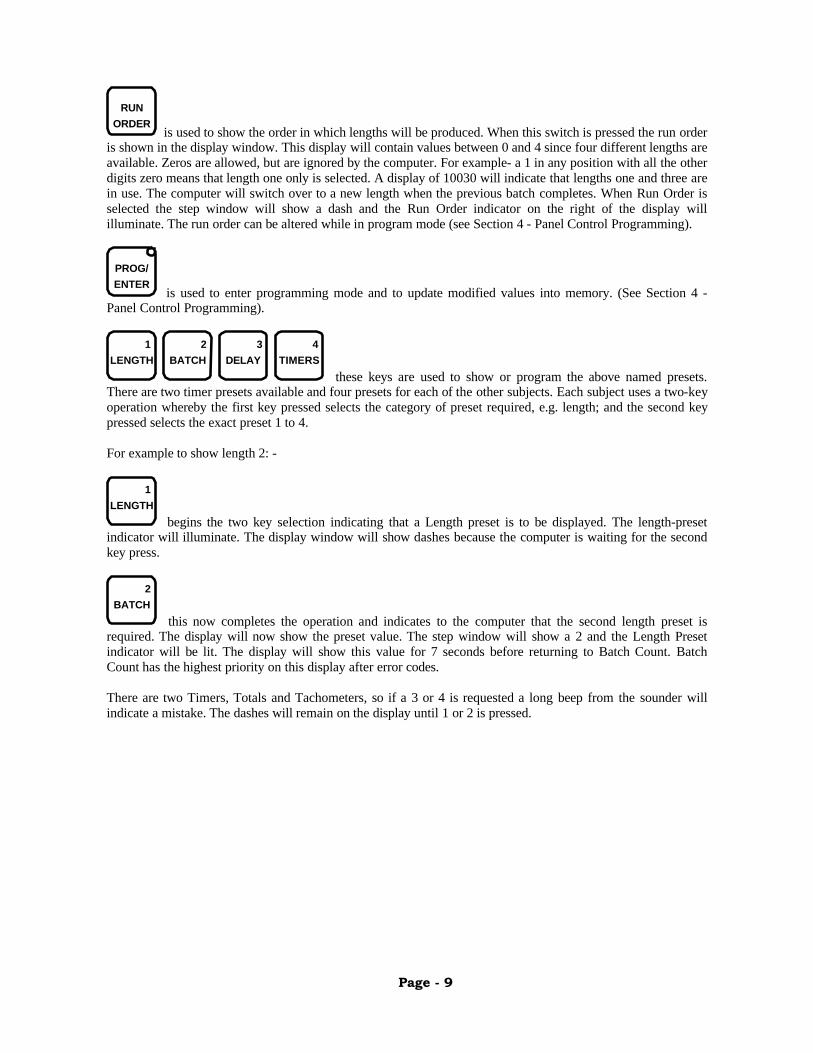
is used to show the order in which lengths will be produced. When this switch is pressed the run orderis shown in the display window. This display will contain values between 0 and 4 since four different lengths areavailable. Zeros are allowed, but are ignored by the computer. For example- a 1 in any position with all the otherdigits zero means that length one only is selected. A display of 10030 will indicate that lengths one and three arein use. The computer will switch over to a new length when the previous batch completes. When Run Order isselected the step window will show a dash and the Run Order indicator on the right of the display willilluminate. The run order can be altered while in program mode (see Section 4 - Panel Control Programming).
PROG/ENTER
is used to enter programming mode and to update modified values into memory. (See Section 4 -Panel Control Programming).
LENGTH BATCH DELAY TIMERS1 2 3 4
these keys are used to show or program the above named presets.There are two timer presets available and four presets for each of the other subjects. Each subject uses a two-keyoperation whereby the first key pressed selects the category of preset required, e.g. length; and the second keypressed selects the exact preset 1 to 4.
For example to show length 2: -
LENGTH1
begins the two key selection indicating that a Length preset is to be displayed. The length-presetindicator will illuminate. The display window will show dashes because the computer is waiting for the secondkey press.
BATCH2
this now completes the operation and indicates to the computer that the second length preset isrequired. The display will now show the preset value. The step window will show a 2 and the Length Presetindicator will be lit. The display will show this value for 7 seconds before returning to Batch Count. BatchCount has the highest priority on this display after error codes.
There are two Timers, Totals and Tachometers, so if a 3 or 4 is requested a long beep from the sounder willindicate a mistake. The dashes will remain on the display until 1 or 2 is pressed.

Page - 10
TOTAL+
does not show a numeric value in the step window. This is because a total can be as much as 10decades in length (9,999,999,999 maximum). Instead a small "o" is shown. If this "o" is shown in the top half ofthe step window, this indicates that the 5 digits displayed are the most significant. This display holds for 7seconds so that the information can be recorded. Next, the display will select an "o" in the lower half of the stepwindow to indicate that the least significant 5 digits of the total are being displayed. The display will nowdefault to show the low order 5 digits until another selection is made. The 5 most significant digits are notshown if they contain zeros.
Most significant 5 decades
STEP
Least significant 5 decades
STEP
These readings indicate a total value of 312,759 pieces.
It is possible to reset Total 1 only. (See Section 5 - Unusual Key Combinations and Section 1 - Clear key andTotal En / Dis key).
Total key functions as an add 1 ("+") operation during programming of a preset. (See Section 4 - Programming).
TACHO-
When selected will latch the tachometer value into the display. Batch Count will not re-appear in thedisplay after the usual 7-second delay. This allows the operator to adjust motor speeds while monitoring thedisplay. After the motor has been adjusted as required, the operator may press the Batch Count switch to force areturn to the Batch Count display.
Tacho 2 reads pulses from an external length measuring encoder directly linked to the profile movement. Thepulses are sampled for a user-defined time in order to indicate the speed of the profile. A decimal point is fixedso that the display reads in tenths of the chosen scale. For example the display may be used to indicate tenths offeet per minute or tenths of metres per minute.

Page - 11
Line Speed Indication
TACHO TOTALBATCHCOUNT
CLEAR- +
LENGTH BATCH DELAY TIMERS
PROG/ENTER
RUNORDER
TOTALEN/DIS
SAMPLECUT
1 2 3 4ALARMRESET
CUTMODE
START
AUXILIARYON
/ STOP
/ OFFTIMER 2 / BATCH
BATCH COUNT
BATCH PRESET
LENGTH PRESET
TOTAL
TIMER PRESET
RUN ORDER
TACHO
TIMER
COUNTER
END SENSE
CONTINUOUS
OPTION
STEP
MOTOR
PUMP / CLUTCH
CHECK / ERROR
TIMER 1
.
Tacho 1 is normally used to indicate blade revolutions per minute with Tacho 2 being used for profile velocity.The above example is showing that the profile is being extruded at 100.0 feet per minute.
When in the programming mode, using Tacho will select the tachometer sample timer. It is also used to reducepreset values and has a subtract 1 ("-") operation. (See Section 4 - Programming. See also Section 7 - SettingTachometer Sample Timers).
BATCHCOUNT
will display the Batch Count being processed. In program mode it is used to select the next digit to bealtered. (See Section 4 - Programming).
CLEARis used to reset the Batch Count. It is also used to reset the preset values to zero when in program
mode. (See Section 4 - Programming. Also see Section 5 - Unusual Key Combinations).
Sounder
All keys cause the sounder to beep. An incorrect key operation will create an extended beep. The batch alarm orother alarms from incorrect running of the machine will also operate this beeper by means of pulsing orstretching the sound of the beep. A sounder output facility is available to enable louder sounders to be used innoisy environments.

Page - 12
Section 4
Panel Control Programming
There are two programming methods used on the LE750. Most programming is carried out via the front panelfor the adjustment of presets, etc.. There is also an external programming device for setting various defaultcharacteristics. (See Section 8 - External Programming Unit).
All presets can be altered via the front panel. The available presets are - 4 Lengths, 4 Batches, 4 Delays, 2Timers, 2 Tachometer Sample Timers, and Run Order.
In Section 3 it was explained that most of these presets require a 2 key operation before the preset value will beshown in the display. Only Run Order uses a single key operation. The key operations for programming are thesame as those for preset inspection. The difference is that the Prog / Enter key has to be pressed before altering apreset, and it must be pressed again when the preset has been modified.
The programming sequence is as follows: -
PROG/ENTER
informs the computer that the operator is about to alter a preset. Prog / Enter indicator inside theswitch will light, and all 6 digits will show dashes to indicate that more key presses are expected.
Operate 1 or 2 key press sequence of the required preset.
For example, for Length 3 use: -
LENGTH1
DELAY3
BATCH COUNT
BATCH PRESET
LENGTH PRESET
TOTAL
TIMER PRESET
RUN ORDER
TACHO
STEP
The required preset will now be shown in the display window. Step will show a value between 1 and 4, or forRun Order a dash will be shown. An indicator to the right of the display will show which preset has beenselected. The program indicator will still be lit. There will be one digit flashing on the preset, since only onedigit can be altered at a time.
Next, alter the value of the display to the required value by using: -
TACHO TOTALBATCHCOUNT
CLEAR- +
TACHO-
will reduce a flashing digit by 1. If the digit is 0 then pressing this key will change it to a 9. Whenprogramming Run Order a 4 will be selected after a 0 since this is the maximum value.
TOTAL+
will increase a flashing digit by 1. If the digit is 9 then pressing this key will change it to a 0. Whenprogramming Run Order a 0 will be shown after a 4.

Page - 13
BATCHCOUNT
will select the next digit to be altered. When the key is pressed the current flashing digit stopsflashing and the digit to the right begins. Pressing this key while the right most digit is selected will select thefirst digit again.
CLEARmay be used to zero the display. All digits in the large window will zero whether they had been
flashing or not. Use this with care - for minor trimming alterations it is unlikely that this key will be used.
PROG/ENTER
this key is used after the preset has been altered to inform the computer that programming iscomplete. The value shown in the display is now entered into its correct preset location, and the display willrevert to showing the condition of the Batch Count. The program indicator will be extinguished.
Example 1: - Modifying Length Preset 3 to 02500.
The display is presently showing Batch Count with a 1 in the Step window. The Batch Count indicator is on.Length 1 is being processed using Counter Mode (Encoder mounted on product).
TACHO TOTALBATCHCOUNT
CLEAR- +
LENGTH BATCH DELAY TIMERS
PROG/ENTER
RUNORDER
TOTALEN/DIS
SAMPLECUT
1 2 3 4ALARMRESET
CUTMODE
START
AUXILIARYON
/ STOP
/ OFFTIMER 2 / BATCH
BATCH COUNT
BATCH PRESET
LENGTH PRESET
TOTAL
TIMER PRESET
RUN ORDER
TACHO
TIMER
COUNTER
END SENSE
CONTINUOUS
OPTION
STEP
MOTOR
PUMP / CLUTCH
CHECK / ERROR
TIMER 1

Page - 14
PROG/ENTER
indicator will light and the display will show dashes. The Batch Count indicator will turn off.
TACHO TOTALBATCHCOUNT
CLEAR- +
LENGTH BATCH DELAY TIMERS
PROG/ENTER
RUNORDER
TOTALEN/DIS
SAMPLECUT
1 2 3 4ALARMRESET
CUTMODE
START
AUXILIARYON
/ STOP
/ OFFTIMER 2 / BATCH
BATCH COUNT
BATCH PRESET
LENGTH PRESET
TOTAL
TIMER PRESET
RUN ORDER
TACHO
TIMER
COUNTER
END SENSE
CONTINUOUS
OPTION
STEP
MOTOR
PUMP / CLUTCH
CHECK / ERROR
TIMER 1
LENGTH1
Length preset indicator will light. Dashes will still be seen in the display and the PROG / ENTERindicator will still be on.
TACHO TOTALBATCHCOUNT
CLEAR- +
LENGTH BATCH DELAY TIMERS
PROG/ENTER
RUNORDER
TOTALEN/DIS
SAMPLECUT
1 2 3 4ALARMRESET
CUTMODE
START
AUXILIARYON
/ STOP
/ OFFTIMER 2 / BATCH
BATCH COUNT
BATCH PRESET
LENGTH PRESET
TOTAL
TIMER PRESET
RUN ORDER
TACHO
TIMER
COUNTER
END SENSE
CONTINUOUS
OPTION
STEP
MOTOR
PUMP / CLUTCH
CHECK / ERROR
TIMER 1

Page - 15
DELAY3
Informs the computer of the numeric value of the previous key press. Step will show a 3, and theLength preset indicator will be on. The display is therefore showing Length Preset 3. Prog indicator will still beon. The previous preset value of will be shown in the large display window with the first digit flashing. In thisexample the previous preset was 01375.
TACHO TOTALBATCHCOUNT
CLEAR- +
LENGTH BATCH DELAY TIMERS
PROG/ENTER
RUNORDER
TOTALEN/DIS
SAMPLECUT
1 2 3 4ALARMRESET
CUTMODE
START
AUXILIARYON
/ STOP
/ OFFTIMER 2 / BATCH
BATCH COUNT
BATCH PRESET
LENGTH PRESET
TOTAL
TIMER PRESET
RUN ORDER
TACHO
TIMER
COUNTER
END SENSE
CONTINUOUS
OPTION
STEP
MOTOR
PUMP / CLUTCH
CHECK / ERROR
TIMER 1
BATCHCOUNT
The first digit is correct, so this key will be pressed to select the next digit to the right. The 0 stopsflashing and the 1 in the next space starts flashing.
STEP
TOTAL+
The second digit should be a 2, so this key is pressed once to change from a 1 to a 2.
STEP
BATCHCOUNT
Press this key again to select the third digit.
STEP
Page - 16
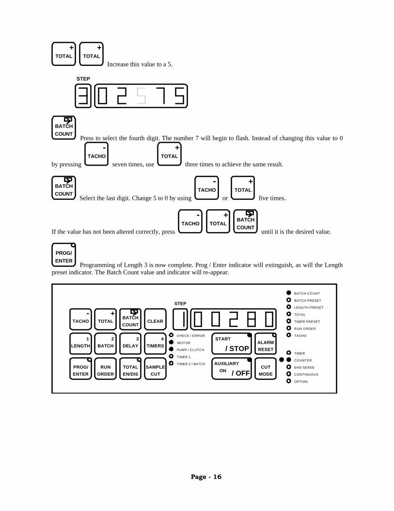
TOTAL+
TOTAL+
Increase this value to a 5.
STEP
BATCHCOUNT
Press to select the fourth digit. The number 7 will begin to flash. Instead of changing this value to 0
by pressing TACHO
-
seven times, use TOTAL
+
three times to achieve the same result.
BATCHCOUNT
Select the last digit. Change 5 to 0 by using TACHO
-
or TOTAL
+
five times.
If the value has not been altered correctly, press TACHO
-TOTAL
+BATCHCOUNT
until it is the desired value.
PROG/ENTER
Programming of Length 3 is now complete. Prog / Enter indicator will extinguish, as will the Lengthpreset indicator. The Batch Count value and indicator will re-appear.
TACHO TOTALBATCHCOUNT
CLEAR- +
LENGTH BATCH DELAY TIMERS
PROG/ENTER
RUNORDER
TOTALEN/DIS
SAMPLECUT
1 2 3 4ALARMRESET
CUTMODE
START
AUXILIARYON
/ STOP
/ OFFTIMER 2 / BATCH
BATCH COUNT
BATCH PRESET
LENGTH PRESET
TOTAL
TIMER PRESET
RUN ORDER
TACHO
TIMER
COUNTER
END SENSE
CONTINUOUS
OPTION
STEP
MOTOR
PUMP / CLUTCH
CHECK / ERROR
TIMER 1
Page - 17
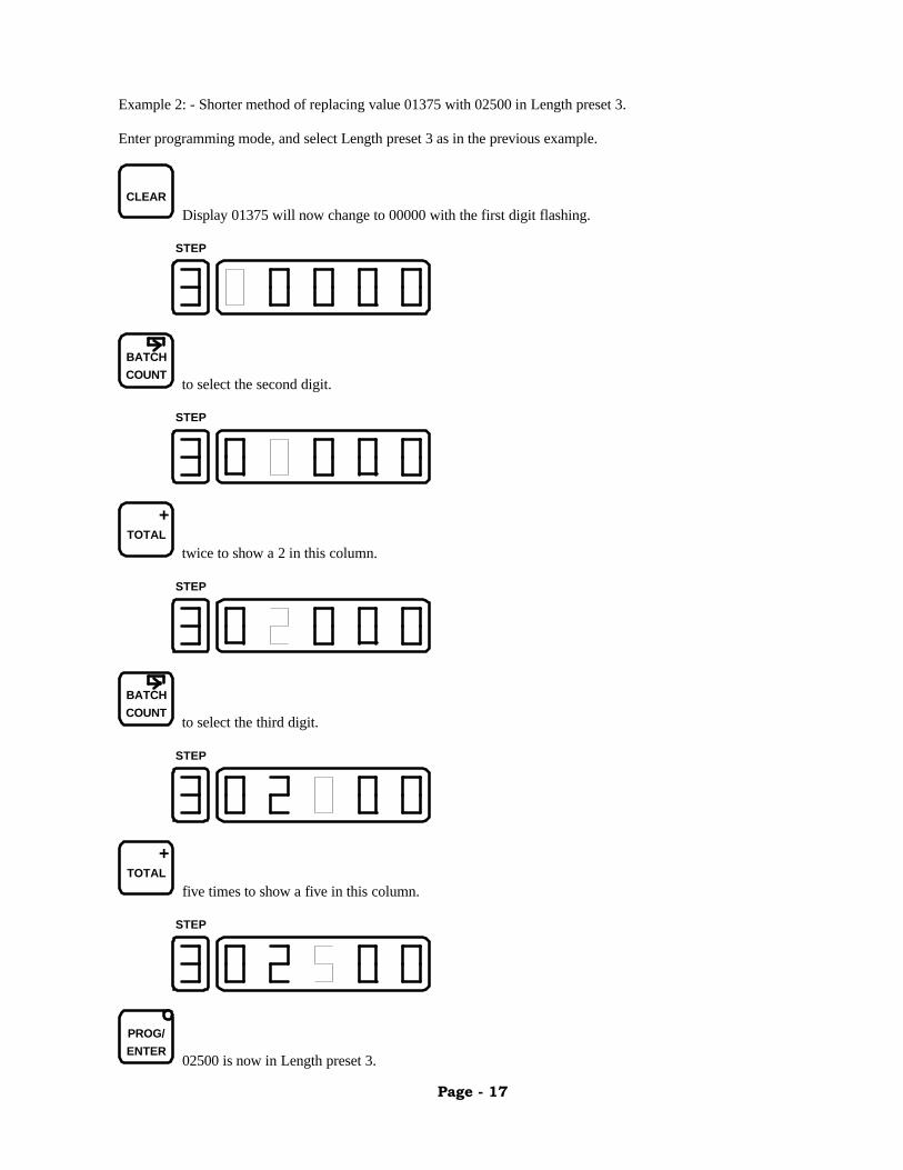
Example 2: - Shorter method of replacing value 01375 with 02500 in Length preset 3.
Enter programming mode, and select Length preset 3 as in the previous example.
CLEARDisplay 01375 will now change to 00000 with the first digit flashing.
STEP
BATCHCOUNT
to select the second digit.
STEP
TOTAL+
twice to show a 2 in this column.
STEP
BATCHCOUNT
to select the third digit.
STEP
TOTAL+
five times to show a five in this column.
STEP
PROG/ENTER
02500 is now in Length preset 3.

Page - 18
Preset Limits and Ranges
It is only possible to program four of the digits when altering delays, timers and Tacho sample timers. The mostsignificant digit after the step window will be blank. The computer will not allow a value of 00000 to be enteredexcept when setting delays and timers.
Lengths and Batches may have any value between 00001 and 99999. A small value in a length preset is allowedbut may show as an error when the cutter is run due to clutch protection limits. The likely error is when thevalue is so short that the cutter is trying to operate at a faster cut rate than is permitted (error 4). The blade mustalso be able to complete a revolution before another cut command is issued.
Delays and Timers can range from between 0000 and 9999. These are normally used for controlling externalequipment only, although the timing can also be used to delay a batch alarm or provide a delayed power downstate. (See Section 7 - Programming Timer outputs).
Tachometer sample timers can only have a value of between 0100 and 2099. (See Section 7 - SettingTachometer sample timers)
Run Order will contain numbers between 0 and 4 only. There are 4 possible lengths so numbers 5 to 9 are notavailable. (See Section 3 - Run order)
Trying to enter values outside of the allowable range results in the computer issuing an extended beep. Theprogram mode will remain active until an acceptable value is entered.
Page - 19
Section 5
Unusual Key Combinations
The key operations described so far have all been fairly straightforward and work in the manner expectedrelating to the wording on the switches. However, functions requiring a defined key sequence are mentioned inthis section.
Total 1 Reset
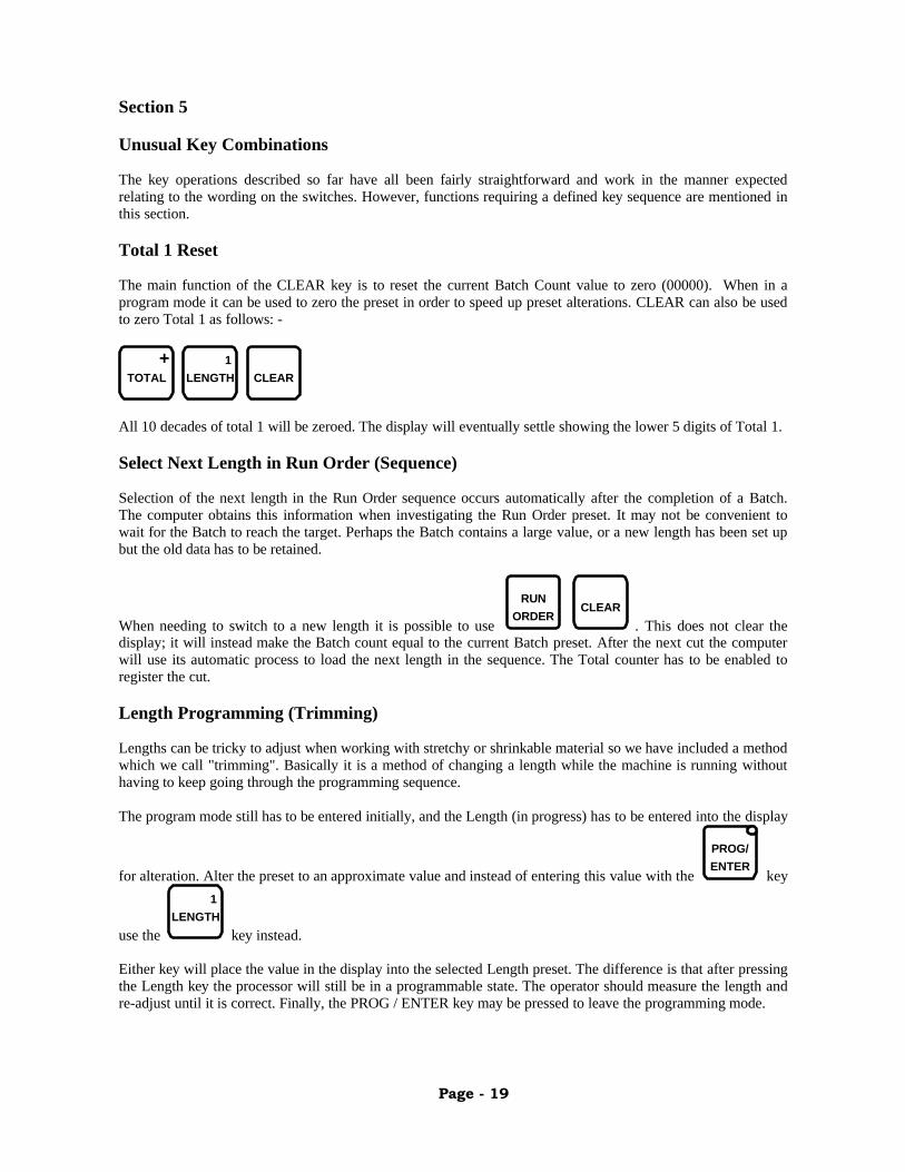
The main function of the CLEAR key is to reset the current Batch Count value to zero (00000). When in aprogram mode it can be used to zero the preset in order to speed up preset alterations. CLEAR can also be usedto zero Total 1 as follows: -
TOTAL+
LENGTH1
CLEAR
All 10 decades of total 1 will be zeroed. The display will eventually settle showing the lower 5 digits of Total 1.
Select Next Length in Run Order (Sequence)
Selection of the next length in the Run Order sequence occurs automatically after the completion of a Batch.The computer obtains this information when investigating the Run Order preset. It may not be convenient towait for the Batch to reach the target. Perhaps the Batch contains a large value, or a new length has been set upbut the old data has to be retained.
When needing to switch to a new length it is possible to use
RUNORDER
CLEAR. This does not clear the
display; it will instead make the Batch count equal to the current Batch preset. After the next cut the computerwill use its automatic process to load the next length in the sequence. The Total counter has to be enabled toregister the cut.
Length Programming (Trimming)
Lengths can be tricky to adjust when working with stretchy or shrinkable material so we have included a methodwhich we call "trimming". Basically it is a method of changing a length while the machine is running withouthaving to keep going through the programming sequence.
The program mode still has to be entered initially, and the Length (in progress) has to be entered into the display
for alteration. Alter the preset to an approximate value and instead of entering this value with the
PROG/ENTER
key
use the LENGTH
1
key instead.
Either key will place the value in the display into the selected Length preset. The difference is that after pressingthe Length key the processor will still be in a programmable state. The operator should measure the length andre-adjust until it is correct. Finally, the PROG / ENTER key may be pressed to leave the programming mode.

Page - 20
Section 6
Single Length Setting
The rotary cutter will usually be set to cut one particular product length, perhaps in batches of 100 or 1,000pieces for packing purposes.
Example: - An order is received for 1,000,000 pieces at 120 mm. These pieces are to be packed in groups of 50.
For this example we are assuming that an encoder measuring wheel providing 4,000 pulses per metre is fitted tothe feed belts or profile. Each millimetre consists of 4 pulses, so to achieve 120 mm we will need to enter120 x 4 = 480. Enter 480 into Length preset 1. Select Counter Mode using the Cut Mode key.
The batch required is 50 so enter 50 into Batch preset 1. Set Run Order to 10000 (the 1 can be entered in anycombination or position; 00100 and 11110 will be equivalent).
Start the machine and concentrate on obtaining the correct profile shape. If the Batch count shows a 1 in the step
window then Length 1 is ready for running. If any other length is in progress use
RUNORDER
followed by
CLEARfollowed by
SAMPLECUT
. After the next cut Length 1 will be ready and active. If not it may have beenbecause the Total En / Dis function was off. Switch it on and try again.
Measure the cut pieces to see if the lengths are correct. If the material shrinks when cooled then wait beforemeasuring. Re-adjust the length if required to compensate for material shrinkage. When altering the length it isadvisable to use the trimming method mentioned in the previous section. When the lengths are correct press
PROG/ENTER
to get back to normal running mode. Reset Batch Count using CLEAR
and prepare to pack the firstbatch. Reset Total 1. Ensure that Total 1 and Batch are enabled. Previous pieces can be discarded.
The Blade revolutions per minute and blade attack angle may have to be adjusted for the type of material beingcut.
Dual Length Setting (Flip-flop)
Dual length suggests that two different lengths can be cut from the same profile. With the LE750 all four lengthscan be set independently and set to operate in a sequence.
For example: - It is possible to cut 5,000 pieces at 120 mm followed by 1,000 pieces at 180 mm. Each length isadjusted individually as in the previous example using Length and Batch presets 1 and 2. Run Order must theninclude a 1 and a 2 to select those presets. Run Order can have 12000, 10020, or 12120 each will perform thesame function.
The use of various lengths of the same profile may be required for the preparation of medical kits. Possibly thebatches will be set to 1. The main use of the flip-flop action is for batch sorting i.e. in conjunction with adischarge table. Timers would be programmed to output the batches into different piles or containers. In thisinstance Length and Batch presets 1 and 2 will have the same values. However, the associated timers will be setdifferently to allow each batch to travel different distances along the table.
Page - 21
Section 7
Programming Timers (Output Triggering)
The timer outputs provided are ideal for downstream-of-the-cutter batch sorting. They can also be used forequipment upstream-of-the-cutter, and for triggering such items as drilling or punching machines that areworking in synchronisation with the same profile. Following is an explanation of the different types of batchsorting available (upstream equipment can be set using the same principles).
Each length has an associated Delay. The length in progress will trigger the delay of the same number wheneach cut is made. The delay value ranges from 0000 to 9,999 milliseconds.
Length 1 triggers Delay 1" 2 " " 2" 3 " " 3" 4 " " 4
At the end of the delay duration one of the two timers will be triggered. The timers are connected directly tooutputs and the value depicts the duration of the timer output in milliseconds. Outputs are likely to be connectedto a transistorised relay, with external load (solenoid) connected via the relay contacts.
Delay 1 triggers Timer 1" 2 " " 2" 3 " " 1" 4 " " 2
It can be seen that Delays 1 and 3 trigger the same timer output. This would be used in the example of adischarge table where Timer 1 output operates the discharge solenoid. Delays 1 and 3 would then be setdifferently so that the batches would travel to different ends of the discharge table.
Re-Triggering Parameters
A timer will begin when an associated delay ends. The output associated with the timer will switch on at thispoint. When the timer ends the associated output will switch off. If a delay is not allowed to time-out then theassociated output will never switch on. Likewise, the output will never switch off if the associated timer is notallowed to time-out.
Example of a product being sorted by Batch using Timer 1 output only
In this example each pulse from the external encoder equals 1 mm. Lengths of 500 mm and batches of 100 arerequired.
Length 1 = 00500Length 3 = 00500
Batch 1 = 00100Batch 3 = 00100
Delay 1 = 1000 (1 second)Delay 3 = 2500 (2.5 seconds)
Timer 1 = 1000 (1 second)
Run Order = 13000
Page - 22
Example of a product being sorted by Batch using both timer outputs
In this example there are two air valves downstream of the cutter angled to blow the cut profile into boxesplaced on either side of the take-off table. They are positioned in the same place with one facing towards thefront and the other towards the back. The same requirements as in the previous example will be processed.
Length 1 = 00500Length 2 = 00500
Batch 1 = 00100Batch 2 = 00100
Delay 1 = 1000Delay 2 = 1000
Timer 1 = 0100Timer 2 = 0100
Run Order = 12000
In this case the timer outputs are set shorter to provide a short puff of air in order to blow the pieces into theirrelevant boxes. As an alternative the solenoids could both be set facing the same way but spaced apart. Delays 1and 2 would then be set to position the batches into two different locations.
Automatic Batch Sorting
Timer 2 can also be used as a Batch output. The requirements are that switch 3 of the External Programmershould be sampled in the "off" position (See Section 8 - External Programming Unit). Also, lengths 2 and 4must be disabled in the Run Order preset otherwise they will be given priority. The computer automaticallyselects Timer 2 as a Batch output when it detects that Lengths 2 or 4 will not be using it. Length 1 completing aBatch will now start Delay 2. Batch 3 will initiate Delay 4 in exactly the same way. Delays 2 and 4 triggerTimer 2 as before.
Secondary batch sorting can then be provided by the Timer 2 output. For example, previously it was shown thatlengths 1 and 3 could be configured to sort a length into two different piles. Timer 2 will now be triggered byeach Batch completion since Run Order does not contain a number 2 or 4. The batch can then be used to operateanother intermediate discharge operation, or to step a conveyor, or to trigger an automatic packing device. It isadvisable to set Delays 2 or 4 slightly longer than Delays 1 or 3 to allow the last length to drop before the batchfunction is operated.
Manual Batch Sorting
When material is being packed manually by an operator some indication of a completed batch could be anadvantage. It may be that a container is being used to collect pieces as they drop from the cutting bush. To fillthis container with 1,000 pieces, for example, may take a long time. The operator may need to carry out othertasks during this period. The external programmer may be used to set the machine for manual or automatic batchusing switch 3 (See Section 8 - External Programming Unit). When set for manual operation, each completionof a batch will cause the Alarm Reset switch indicator to flash. The buzzer may also be selected to sound bysetting switch 4 of the external programmer. The operator would then press the Alarm Reset to switch off thealarm after he has attended the situation.

Page - 23
Example: - Length 1 is being used and is cutting pieces at 100 mm; the Batch is set to 1,000. The operator seesthe indicator flashing and/or hears the alarm so attends to the machine. He replaces the container, and notes thevalue shown in the Batch count display. The number of pieces shown on the display is surplus. This amount issimply removed and placed in the new box. The operator then resets the alarm and seals the full box.
Timer 2 / Batch will latch on in this mode so it may be used to operate a flashing beacon. The Alarm Reset keywill reset the latch.
Run Order must not contain a 2 or a 4 for the same reasons discussed with the automatic batch processingexample. The Batch alarm activation may be delayed by the values set in Delays 2 and 4. This too was explainedin the examples on automatic batch processing.
Automatic Power Down
The external programmer can be used to switch off the cutter and/or auxiliary once the batch is complete. Thiscan be useful when preparing medical kits from material supplied on a reel. This function is not recommendedfor use on extruded lines. Switches 5 and 6 in conjunction with switch 3 on the external programmer set theautomatic power down. (See Section 8 - External Programming Unit).
Delays 2 or 4 should be set long enough to allow the last piece of the batch to be cut successfully before themachine powers down.
Complete Internal System Block Diagram
DELAY 1
DELAY 2
DELAY 3
DELAY 4
TIMER 1
TIMER 2
LATCH
BATCH 1
BATCH 2
BATCH 3
BATCH 4
LENGTH 1
LENGTH 2
LENGTH 3
LENGTH 4
TIMER 1 OUTPUT
TIMER 2 OUTPUT
Run Orderincludes a2 or a 4
EP3 setRun Orderexcludes a2 or a 4
Alarm orExternalReset
ALARM RESETINDICATOR
BUZZER
POWER DOWN
POWER DOWN
AUXILIARY
CUTTER
EP4
EP5
EP6
EP=External Programmer
Page - 24
Setting Tachometer Sample Timers
A Tachometer is used to inform the operator of the speed of a particular device. It would be set to showmeaningful units of measure. For the rotary cutter this is usually the blade revolution per minute, although themotor revolutions per minute may be preferred. Similarly, it may be required that the line speed is shown in feetor metres per minute.
The LE750 has 2 digital tachometers. Tachometer 1 is set for showing blade revolutions per minute andTachometer 2 is set to show line speed. A cutter will most likely be set to show blade speed when supplied. Thiswould have been factory preset to match the internal pulley ratios and should not require alteration. The feedtachometer may also be pre-set before delivery on occasions when an external encoder is supplied with themachine.
If either tachometer needs re-calibrating use the following formulae: -
Cutter Tachometer Example
The equation to calculate the sample timer is: -
60,000 x B = Sample valueT X M
T = teeth on pick upB = Blade RevolutionM = Motor Revolution
A 60-tooth pulley is attached to the motor shaft (this also acts as a flywheel). The sensor is picking up a signalfrom this wheel. For each revolution of clutch output the input (motor) has to rotate twice. Set the timer up asfollows: -
60,000 x 1 = 50060 x 2
The value 60,000 is used to convert a minute to milliseconds.
When the motor is rotating at 800 revolutions per minute, the blade should be rotating at 400 revolutions perminute.
800 x 60 = 800 pulses per second60
Sample timer 1 is set to 500 so Tachometer 1 display will read: -
800 x 500 = 4001,000
This reading is in fact showing the amount of pulses received in 500 milliseconds but is interpreted as Bladerevolutions per minute.
Page - 25
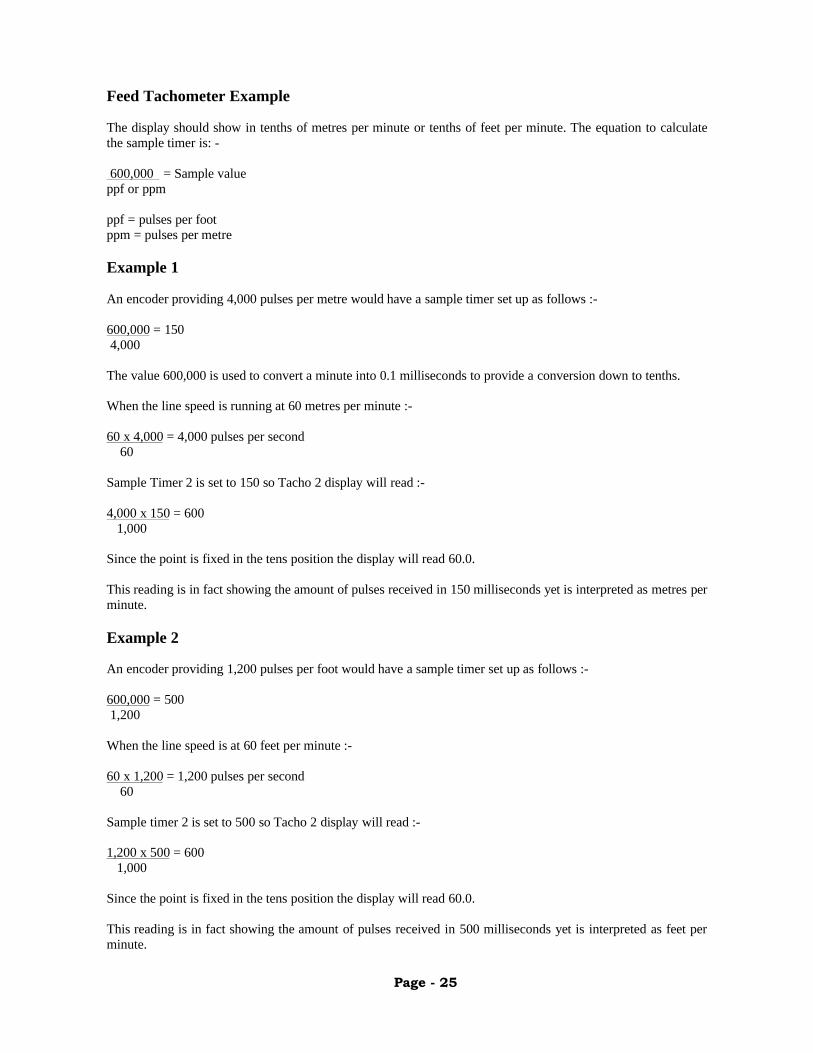
Feed Tachometer Example
The display should show in tenths of metres per minute or tenths of feet per minute. The equation to calculatethe sample timer is: -
600,000 = Sample valueppf or ppm
ppf = pulses per footppm = pulses per metre
Example 1
An encoder providing 4,000 pulses per metre would have a sample timer set up as follows :-
600,000 = 1504,000
The value 600,000 is used to convert a minute into 0.1 milliseconds to provide a conversion down to tenths.
When the line speed is running at 60 metres per minute :-
60 x 4,000 = 4,000 pulses per second60
Sample Timer 2 is set to 150 so Tacho 2 display will read :-
4,000 x 150 = 6001,000
Since the point is fixed in the tens position the display will read 60.0.
This reading is in fact showing the amount of pulses received in 150 milliseconds yet is interpreted as metres perminute.
Example 2
An encoder providing 1,200 pulses per foot would have a sample timer set up as follows :-
600,000 = 5001,200
When the line speed is at 60 feet per minute :-
60 x 1,200 = 1,200 pulses per second60
Sample timer 2 is set to 500 so Tacho 2 display will read :-
1,200 x 500 = 6001,000
Since the point is fixed in the tens position the display will read 60.0.
This reading is in fact showing the amount of pulses received in 500 milliseconds yet is interpreted as feet perminute.
Page - 26
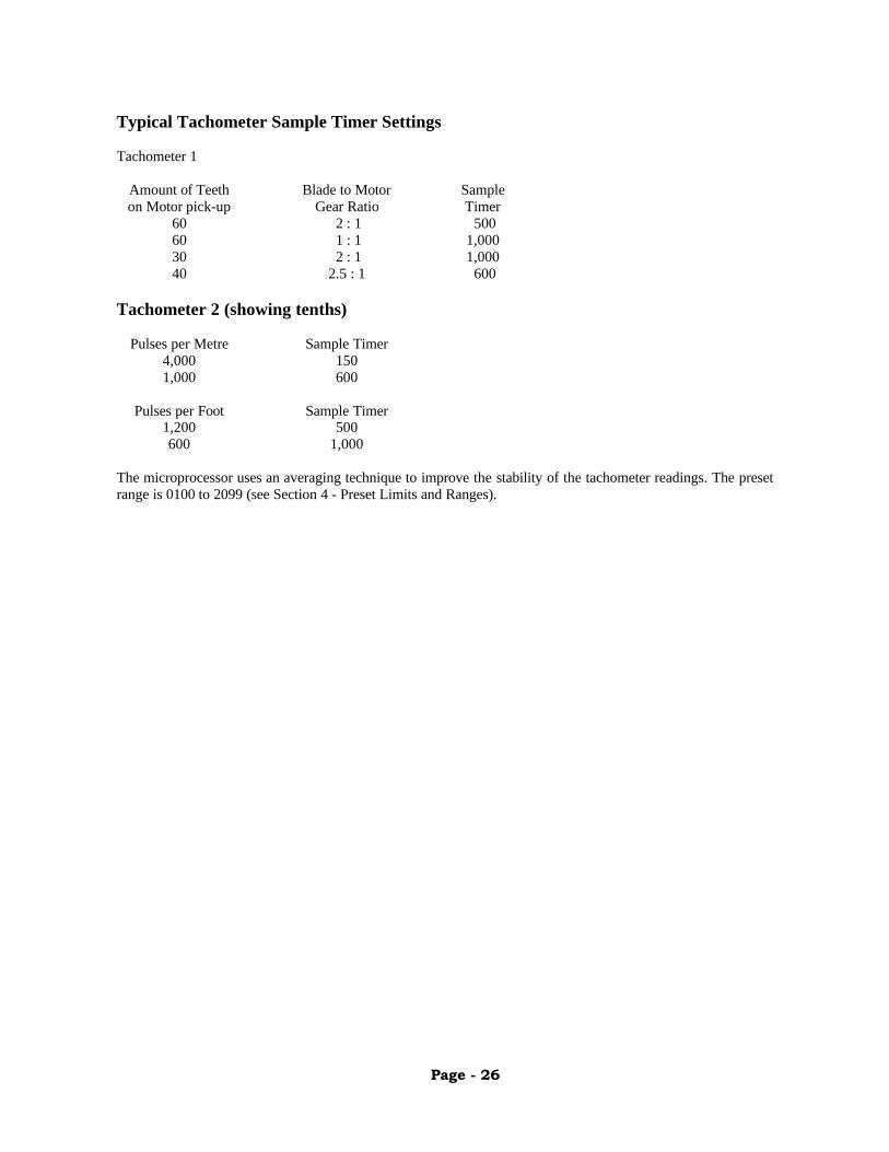
Typical Tachometer Sample Timer Settings
Tachometer 1
Amount of Teeth Blade to Motor Sampleon Motor pick-up Gear Ratio Timer
60 2 : 1 50060 1 : 1 1,00030 2 : 1 1,00040 2.5 : 1 600
Tachometer 2 (showing tenths)
Pulses per Metre Sample Timer4,000 1501,000 600
Pulses per Foot Sample Timer1,200 500600 1,000
The microprocessor uses an averaging technique to improve the stability of the tachometer readings. The presetrange is 0100 to 2099 (see Section 4 - Preset Limits and Ranges).
Page - 27
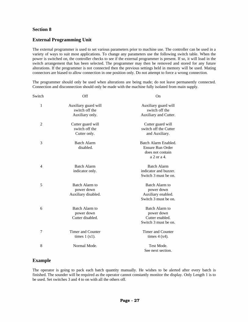
Section 8
External Programming Unit
The external programmer is used to set various parameters prior to machine use. The controller can be used in avariety of ways to suit most applications. To change any parameters use the following switch table. When thepower is switched on, the controller checks to see if the external programmer is present. If so, it will load in theswitch arrangement that has been selected. The programmer may then be removed and stored for any futurealterations. If the programmer is not connected then the previous settings held in memory will be used. Matingconnectors are biased to allow connection in one position only. Do not attempt to force a wrong connection.
The programmer should only be used when alterations are being made; do not leave permanently connected.Connection and disconnection should only be made with the machine fully isolated from main supply.
Switch Off On
1 Auxiliary guard will Auxiliary guard willswitch off the switch off the
Auxiliary only. Auxiliary and Cutter.
2 Cutter guard will Cutter guard willswitch off the switch off the CutterCutter only. and Auxiliary.
3 Batch Alarm Batch Alarm Enabled.disabled. Ensure Run Order
does not containa 2 or a 4.
4 Batch Alarm Batch Alarmindicator only. indicator and buzzer.
Switch 3 must be on.
5 Batch Alarm to Batch Alarm topower down power down
Auxiliary disabled. Auxiliary enabled.Switch 3 must be on.
6 Batch Alarm to Batch Alarm topower down power down
Cutter disabled. Cutter enabled.Switch 3 must be on.
7 Timer and Counter Timer and Countertimes 1 (x1). times 4 (x4).
8 Normal Mode. Test Mode.See next section.
Example
The operator is going to pack each batch quantity manually. He wishes to be alerted after every batch isfinished. The sounder will be required as the operator cannot constantly monitor the display. Only Length 1 is tobe used. Set switches 3 and 4 to on with all the others off.
Page - 28
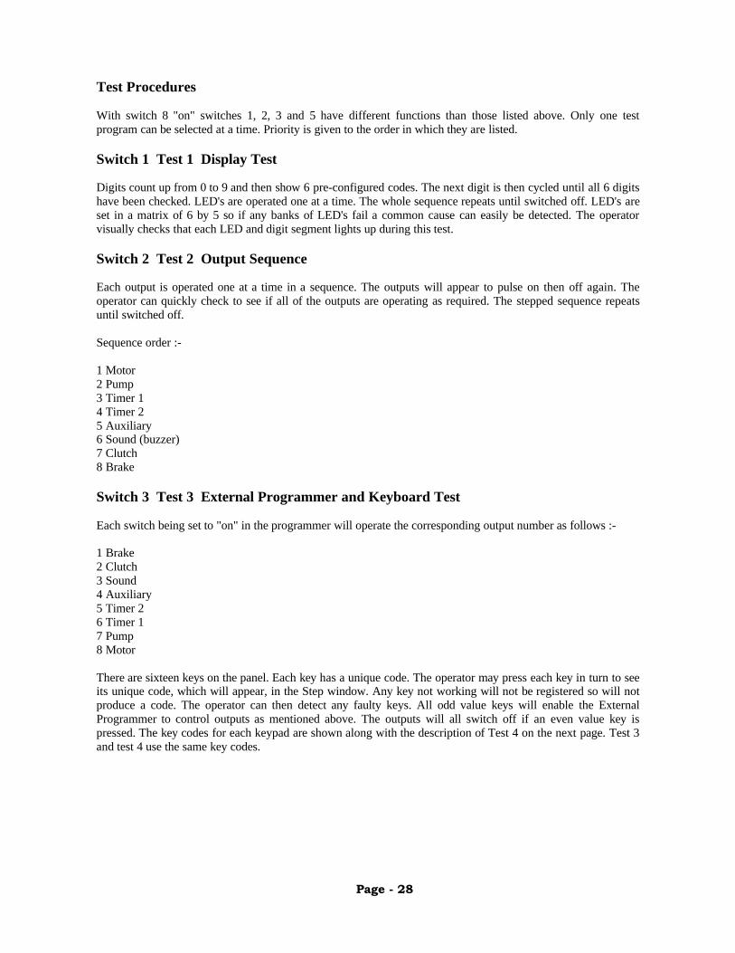
Test Procedures
With switch 8 "on" switches 1, 2, 3 and 5 have different functions than those listed above. Only one testprogram can be selected at a time. Priority is given to the order in which they are listed.
Switch 1 Test 1 Display Test
Digits count up from 0 to 9 and then show 6 pre-configured codes. The next digit is then cycled until all 6 digitshave been checked. LED's are operated one at a time. The whole sequence repeats until switched off. LED's areset in a matrix of 6 by 5 so if any banks of LED's fail a common cause can easily be detected. The operatorvisually checks that each LED and digit segment lights up during this test.
Switch 2 Test 2 Output Sequence
Each output is operated one at a time in a sequence. The outputs will appear to pulse on then off again. Theoperator can quickly check to see if all of the outputs are operating as required. The stepped sequence repeatsuntil switched off.
Sequence order :-
1 Motor2 Pump3 Timer 14 Timer 25 Auxiliary6 Sound (buzzer)7 Clutch8 Brake
Switch 3 Test 3 External Programmer and Keyboard Test
Each switch being set to "on" in the programmer will operate the corresponding output number as follows :-
1 Brake2 Clutch3 Sound4 Auxiliary5 Timer 26 Timer 17 Pump8 Motor
There are sixteen keys on the panel. Each key has a unique code. The operator may press each key in turn to seeits unique code, which will appear, in the Step window. Any key not working will not be registered so will notproduce a code. The operator can then detect any faulty keys. All odd value keys will enable the ExternalProgrammer to control outputs as mentioned above. The outputs will all switch off if an even value key ispressed. The key codes for each keypad are shown along with the description of Test 4 on the next page. Test 3and test 4 use the same key codes.
Page - 29
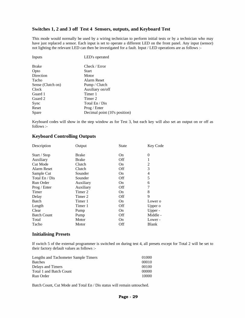
Switches 1, 2 and 3 off Test 4 Sensors, outputs, and Keyboard Test
This mode would normally be used by a wiring technician to perform initial tests or by a technician who mayhave just replaced a sensor. Each input is set to operate a different LED on the front panel. Any input (sensor)not lighting the relevant LED can then be investigated for a fault. Input / LED operations are as follows :-
Inputs LED's operated
Brake Check / ErrorOpto StartDirection MotorTacho Alarm ResetSense (Clutch on) Pump / ClutchClock Auxiliary on/offGuard 1 Timer 1Guard 2 Timer 2Sync Total En / DisReset Prog / EnterSpare Decimal point (10's position)
Keyboard codes will show in the step window as for Test 3, but each key will also set an output on or off asfollows :-
Keyboard Controlling Outputs
Description Output State Key Code
Start / Stop Brake On 0Auxiliary Brake Off 1Cut Mode Clutch On 2Alarm Reset Clutch Off 3Sample Cut Sounder On 4Total En / Dis Sounder Off 5Run Order Auxiliary On 6Prog / Enter Auxiliary Off 7Timer Timer 2 On 8Delay Timer 2 Off 9Batch Timer 1 On Lower oLength Timer 1 Off Upper oClear Pump On Upper -Batch Count Pump Off Middle -Total Motor On Lower -Tacho Motor Off Blank
Initialising Presets
If switch 5 of the external programmer is switched on during test 4, all presets except for Total 2 will be set totheir factory default values as follows :-
Lengths and Tachometer Sample Timers 01000Batches 00010Delays and Timers 00100Total 1 and Batch Count 00000Run Order 10000
Batch Count, Cut Mode and Total En / Dis status will remain untouched.

Page - 30
Error Codes
Code Caused by Remedy
1 Guard 1 is open. Check Guard switchesand connections.
2 Guard 2 is open. As 1.
3 Blade rotating Reduce blade speed.too fast may
damage clutch.
4 Trying to operate Set a longer Length.clutch in excess
of safe limit.
5 Blade Jammed. Clear jam. Faultcould also be causedby a fault in the High
Speed Switch or clutch.
6 Clutch was triggered Check connections.but did not switch Check High Speed Switch
on. and clutch.
7 Brake was triggered As 6.but did not switch
on.
8 A signal was detected Brake not holding on.from the brake sensor Check clutch and Highwhen the brake was Speed Switch.
already on. Occasionally, error 8will happen just at the
moment when the motor isstopping. In this instancethe error may be ignored.It may be caused by the
delay in braking.
9 The value in the cut Try using the sample key.preset is too short This initiates a cut and
for the processor to re-sets the preset. Ifhandle. To avoid a the error remains then
possible lock up the the value is deemed tooprocessor has set short to be processed.the preset to an
extremely high value.

Page - 31
External Connections Terminal Strip
Upper Pin Lower
Motor Relay 1 0 voltsPump Relay 2 12 voltsHSS Brake 3 Brake Sensor -HSS Clutch 4 Brake Sensor +HSS Sense 5 Guard 2 -HSS 0v 6 Guard 2 +HSS 24v 7 Auxiliary CDirection 8 Auxiliary EGuard 1 9 Timer 1 C12 volts 10 Timer 1 E0 volts 11 Timer 2 CClock 12 Timer 2 ETacho - 13 SoundTacho + 14 Opt Input12 volts 15 12 volts0 volts 16 0 voltsOpto - 17 SyncOpto + 18 Reset
All the terminals are isolated from the microprocessor 5-volt power supply via opto isolation circuitry.
High Speed Switch / Main Relay Connections
The first 7 terminals on the upper row are connected to the High Speed Switch and to the main relays. The HighSpeed Switch provides power for this section. Without this supply these outputs would not be present. Eachoutput is via optically isolated drivers and should read 0 volts when off, or 15 volts when on. The current driveis 7-milliamp maximum each.
See Electrical Schematic drawing 1
Balanced Inputs
Balanced inputs are provided for the Tacho, Opto (End Sense) and Brake sensor. These voltages can beconnected to any external supply source between 5 and 30 volts D.C.. Guard 2 is also a balanced input but israted at 10 to 25 volts D.C.. The 12-volt supply terminals present on the rear terminal strip may be used as thesupply source for these inputs. Current-limiting resistors have been selected to suit these ranges and areinternally fitted.
See Electrical Schematic drawing 2
Other un-balanced inputs are referenced to the microprocessor 12-volt power supply. Current-limiting resistorshave been internally fitted to suit.
Sync
This input is available to re-start the Run Order sequence. It allows an external device to be able to synchronisethe cutting sequence. The sync input may initiate a cut (see Opt function), reset the batch, and load in the firstlength preset shown in the Run Order.

Page - 32
Opt
This input changes the behaviour of the Sync input. The level of the Opt input will determine whether the Syncedge will make a cut or not. With this input left open or held at 12 volts the Sync edge will initiate a cut. Whenconnected to 0 volts no cut will occur except when the first chosen Length is complete.
Reset
An external reset is available which is used to reset the batch alarm. It has exactly the same function as theAlarm Reset on the fascia panel.
Direction
At present this input is not being used.
Balanced Outputs
Timers 1 and 2, and Auxiliary are available as optically isolated N.P.N. transistor outputs (C = Collector, E =Emitter). These can be connected to isolated circuits using a power source between 5 and 24 volts. In non-isolated applications the controllers' 12 volts may be used. Power dissipation is 150-milliwatts maximum.Larger current drive must be provided by an external amplified source. An external current limiting resistor (orload) is required which must be selected to limit the above maximum ratings.
See Electrical Schematic drawings 3A and 3B.
Transistor Potential 3A Potential 3B
on v- v+off v+ v-
Typical Resistive Load
5v = 500R10v = 1K
External sounder load must be less than 100-milliamps. Suitable piezo-electric type buzzers are generallyavailable.
Power Dissipation of 12 volt Supply
The 12 volt power supply available on the external connections is designed to supply all of the sensors requiredto achieve a typical cutting / packing system. The sum total of all loads connected to this supply should notexceed 300-milliamps. Relays and solenoids cannot be directly driven from any outputs or supply. To operatesuch devices an output needs to operate an external transistor or transistorised relay connected to a morepowerful source.
See Electrical Schematic drawing 4
Cleaning
The panel of the microprocessor controller is designed as a flat membrane-type to allow for easy cleaning. Asoft cloth with clean water or with a mild detergent is all that is required to clean the panel. Wipe dry afterwards.Ensure that the unit is fully isolated when carrying out this procedure. Also, make sure the unit is totally drybefore applying power.
Related Documents


![[ENG] Instruction manual for laser cutter · 2018-04-26 · Instruction manual for laser cutter ... Should a ”User Account ontrol”-notification show up when running the file,](https://static.cupdf.com/doc/110x72/5ea93618a87f4f1b7b124442/eng-instruction-manual-for-laser-cutter-2018-04-26-instruction-manual-for-laser.jpg)