All 316 SS Construction TFE Wetted Parts LOW PRESSURE DIAPHRAGM LOW PRESSURE DIAPHRAGM INSTALLATION, OPERATION, AND MAINTENANCE MANUAL S E R I E S O F M E T E R I N G P U M P S S E R I E S O F M E T E R I N G P U M P S LD

Welcome message from author
This document is posted to help you gain knowledge. Please leave a comment to let me know what you think about it! Share it to your friends and learn new things together.
Transcript

All 316 SS Construction
TFE Wetted Parts
LOW PRESSURE DIAPHRAGMLOW PRESSURE DIAPHRAGM
INSTALLATION, OPERATION, ANDMAINTENANCE MANUAL
S E R I E S O F M E T E R I N G P U M P SS E R I E S O F M E T E R I N G P U M P SLD


TABLE OF CONTENTS
Section Description Page
1.0 FUNCTIONAL DESCRIPTION 2
1.1 Physical Description 3
1.2 Capabilities 3
1.3 Specifications Table 4
1.4 General Operating Sequence 4
2.0 INSTALLATION OF PUMP AND CONTROLLER 5
2.1 General Requirements 5
2.2 Pump Location & Dimensions 5
2.3 Suction / Discharge Piping 5
2.4 Air / Gas Supply 6
3.0 START UP, OPERATION & SHUTDOWN 6
3.1 Start Up 6
3.2 Operation 8
3.3 Shutdown / Storage 8
4.0 MAINTENANCE 9
4.1 Disassembly and Assembly 9
4.1.2 Controller 9
4.1.3.1 LD100 Series 11
4.1.3.2 LD200 Series 13
4.1.3.3 LD400 Series 13
4.2 Preventive Maintenance 14
4.3 Troubleshooting Guide 15
5.0 LIMITED WARRANTY 14
INTRODUCTION AND OVERVIEWThis manual contains specific, comprehensive procedures for the installation, operation, and maintenance of the Williams LD-Series PneumaticMetering Pumps.
For user convenience, the manual is divided into four sections:
SECTION 1.0: FUNCTIONAL DESCRIPTION
SECTION 1.0 contains a physical description, the capabilities, and the operating sequence of the pumps.
SECTION 2.0: INSTALLATION OF PUMP AND CONTROLLER
SECTION 2.0 contains specific procedures for installing the pumps and their various components including the controller.
SECTION 3.0: STARTUP, OPERATION, SHUTDOWN, AND STORAGE
SECTION 3.0 contains procedures for setup, operation, shutdown, and storage of the pumps.
SECTION 4.0: MAINTENANCE & TROUBLESHOOTING
SECTION 4.0 contains procedures for both regular and corrective maintenance.
SECTION 5.0: LIMITED WARRANTY
SECTION 5.0 contains information outlining the limited warranty offered with the pump.

2
Air is supplied at a constant regulated pressure to the CONTROLLER. This air passesthrough the controller to the pump via the CONTROL SPOOL and SUPPLY VALVE. At thesame time, a small volume of air travels up the CONTROL AIR PASSAGE through theNEEDLE VALVE to the top of the CONTROL SPOOL. The NEEDLE VALVE CONTROLS thespeed at which the pressure builds on top of the CONTROL SPOOL. As the pressureincreases, the CONTROL SPOOL descends, closing the SUPPLY VALVE and opening theEXHAUST VALVE. As the pressure is exhausted from both the pump and the top of theCONTROL SPOOL, the CONTROL SPOOL is then forced upward, starting another cycle.The NEEDLE VALVE ultimately controls the rate at which the OSCILLAMATIC cycles.
The PNEUMATIC RELAY is a pilot-operated valve designed to provide the higher air or gas flow rates necessary for for higher pressures from100 to 150 psi. The PNEUMATIC RELAY is actuated by the pulses produced by the OSCILLAMATIC CONTROLLER.
CONTROLLER
PUMP
RELAY
FLOW DISCHARGECONTROLLER
RELAY PO4-6S
PUMP 1EXHAUST
AIR SUPPLY
PUMP 2EXHAUST
PUMP 1
PUMP 2
FLOW INLET
CONTROLLER-PNEUMATIC RELAY COMBINATION
TYPICAL INSTALLATION
OSCILLAMATIC® CONTROLLER
PILOT PULSES FROMCONTROLLER
EXHAUST
SINGLE ACTING DOUBLE ACTING
PUMP
SUPPLYPRESSURE
SUPPLY PRESSURE
EXHAUST NO. 1
PUMP POWERSTROKE NO. 1
PUMP RETURNSTROKE NO. 2
EXHAUST NO. 2
TYPICAL INSTALLATIONFOR 150 PSI (10.3 BAR)
AIR SUPPLY
TYPICAL INSTALLATION FORDUPLEXED PUMPS
Includes:1 Controller 2 Pumps1 Relay 1 Manifold
PILOT PULSESFROMCONTROLLER
STROKE RATECONTROL KNOB NEEDLE
VALVE
OPTIONAL 3-15CONTROL CONTROL PORTAIR PASSAGE
CONTROL SPOOL
SUPPLYTO PUMP AIR/GAS SUPPLY
TO CONTROLLER
SUPPLY VALVEEXHAUSTTO PUMP
EXHAUST VALVE
CONTROL METHODS FOR THE PUMP
SOLENOID VALVESThe pumps can be automated byreplacing the CONTROLLER with a3-way electro-pneumaticSOLENOID VALVE. The SOLENOIDVALVE can be cycled in order toachieve the desired pump output.Flow tracking can be accomplishedby having a FLOWMETER or PHMETER signal interpreted by ourWPC9001 or a PLC.
PUMP &CONTROLLER
DUMP VALVE
AIR/GASDRYER
PRESSUREREGULATOR
AIR/GASSUPPLY
INLET FILTERCHEMICAL
SUPPLY
(1)
FLOWMETER (optional)
PROCESS FLUID
CHECK VALVE
TOTALIZER
PUMP & (1)
3-WAY SOLENOID VALVE
FLOWOR PHMETER
PROCESS FLUID
WPC 9001OR PLC
24VDCPULSE
4-20mASIGNAL
CHECK VALVE
FLOWMETER
TOTALIZER
PUMP
DUMP VALVE
AIR/GASDRYER PRESSURE
REGULATOR
AIR/GASSUPPLY
(1)
RATE SETTINGGAUGE
INLET FILTER
CHEMICALSUPPLY
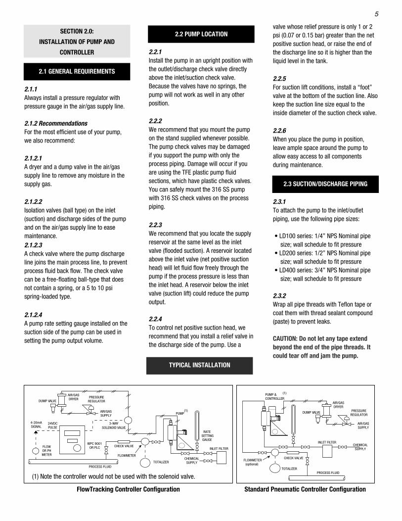
FlowTracking Controller Configuration
(1) Note the controller would not be used with the solenoid valve.
Standard Pneumatic Controller Configuration

3
1.2.1.2 Air/Gas Supply Pressure:A regulator always must be used to controlthe air/gas power supply. The controllerwill operate with supply pressures up to100 psig (6.9 bar). With supply pressuresover 100 psig (6.9 bar), it is essential touse a pressure regulator between thesupply and the controller to prevent thehigher pressures from accidentallydamaging the controller. If you need tooperate at supply pressures over 125 psig(8.62 bar), contact your distributor orWilliams Instrument for information on howto apply our pneumatic relay.
* The process pressure is the pressure of the streamor reservoir into which the metering pump isdischarging.
1.2.2 Pumps1.2.2.1 ViscositiesThe pumps will provide catalogperformance on fluids with viscosities upto 6000 SSU (Saybolt Second Universal) or1280 CP (Centipoise). Although the pumpscan operate on higher viscosity fluids,there will be a reduction in catalogperformance.
1.2.2.2 Suction LiftSuction lift reduces maximum pumpingvolume. The maximum suction lift withoutflow loss that each pump can handle is: 60inches (1524 mm) (all models)
A foot valve is recommended in the supplyline of the suction check valve.
SECTION 1.0: FUNCTIONALDESCRIPTION
1.1 PHYSICAL DESCRIPTION
1.1.1 Mark X Oscillamatic® Controller(35-100 psi)The controller consists of an upper and alower chamber, separated by a slidingspool. A capillary tube, controlled by aneedle valve, transfers the supply air/gasfrom the lower to the upper chamber.When the spool is in its highest position, apilot plug closes a vent and opens thesupply air/gas to the pump. When thespool is in its lowest position, the pilot plugprevents the supply air/gas from enteringthe pump, and opens the air/gas vent to letit exhaust the pump. The spool thenreturns to its highest position to repeat thecycle.
1.1.2 Mark XII Oscillamatic® Controller(30 - 100 psi)The Mark XII Controller operates on thesame operating principal as the Mark XController. The Mark XII has the samechambers which are separated withflexible diaphragms rather than slidingseals. See paragraph 1.1.1. above for adescription of operation.
1.1.3 PumpThe pneumatic diaphragm metering pump(DWG. 1) consists of a liquid chamber andan air chamber separated by a diaphragm.In the liquid chamber, the suction (inlet)and discharge (outlet) ports have checkvalves that control the direction of the fluidflow. A pipe nipple connects the controllerto the pump air chamber. In the airchamber, the air/gas power supply fromthe controller enters and exhausts throughthe pipe nipple connector. When thecontroller exhausts the air/gas supply, thefluid suction pressure and the return springforce the diaphragm backwards. Thediaphragm stops when the end of thediaphragm stem, which is attached to theair chamber side of the diaphragm,collides with the end of the stroke adjuster.
1.2 CAPABILITIES
1.2.1 Controller1.2.1.1 Air/Gas SupplyThe Controller will operate with air orvirtually any gas, such as nitrogen ornatural gas, that is dry and clean. Nooilers. No oxygen.
WARNING: TO PREVENT INJURY WHEN YOUUSE A FLAMMABLE GAS SUCH AS NATURALGAS, MAKE SURE THAT YOU VENT IT SAFELY.CAUTION: If you think the gas might damagethe standard viton seals in either the pumpor the controller, contact your distributor orWilliams Instrument for advice.
SUPPLY BODY STROKES ELASTOMER SPOOL MODELS PRESSURE MATERIAL (SPM) OPTIONS STYLE
MK XIIA 30-100 PSI (2.0-6.9 Bar) 316 ss 1 - 45 Neoprene, Buna N, Viton® Diaphragm
MK X 35-100 PSI (2.4-6.9 Bar) 316 ss 1 - 45 Buna/TFE, Viton®/TFE U-Cup
CONTROLLER COMPARISON

4
When the controller sends the supplyair/gas into the motor chamber through thenipple connector, the air/gas pressure onthe diaphragm overcomes the combinedforce of the process fluid pressure on thediaphragm and the diaphragm returnspring. The pressure moves the diaphragminto the pump liquid chamber. When theexternal controller exhausts the air/gas,the diaphragm return spring pulls thediaphragm out of the pump liquidchamber.
1.4.3 Pump (Liquid Chamber)The pump operating cycle consists of twoparts: discharge and suction.Discharge occurs when the diaphragmmoves into the pump liquid chamber,decreasing the fluid chamber’s volume,and raising the pressure of the fluid in thechamber. This higher pressure closes thesuction check valve and opens thedischarge check valve, sending the fluidinto the discharge line. The suction part ofthe cycle occurs when the diaphragmmoves out of the pump chamber,increasing the chamber volume andlowering the pressure of the fluid in theliquid chamber. This lower pressure opensthe suction check valve and closes thedischarge check valve, sending fluid fromthe suction line into the pump liquidchamber.
When high pressure air/gas enters thesupply port, it passes around and throughthe spool and past the open upper seat tothe motor cylinder port.High pressure air/gas passes through thecontrol passage in the controller, past thevalve stem, and into the valve body upperchamber which causes pressure to buildup in the chamber. Because the surfacearea of the upper U-cup diaphragm ismuch larger than that of the middle U-cupdiaphragm, the downward force on thespool is greater than the upward force.This pressure pushes the spool down untilthe pilot plug seats itself on the uppervalve seat, shutting off the air/gas supply.As the spool continues to move down, itpushes the pilot plug until the plug isunseated from the lower valve seat andallows the air/gas to exhaust through thelower valve from both the motor cylinderand the valve body volume chamber.
When the pressure in the chamber is lowenough, the spool spring starts pushingthe spool upward. The exhaust springpushes the pilot plug upward, and thecontroller returns to its initial position.
1.4.2 Pump Motor (Air Chamber)Air/gas and the diaphragm return springforce the diaphragm to move alternatelyinto and out of the pump liquid chamber.
1.2.2.3 Operating Temperature RangeThe range of operating temperaturedepends on the pump and diaphragmmaterial. The recommended range withour standard PTFE diaphragm is:
LIQUID END TEMPERATUREMATERIAL RANGE
316 SS +40ºF to 185ºFPTFE +40ºF to 185ºF
Contact your distributor or WilliamsInstrument if you need further informationon the operating temperature range.
1.2.2.4 Metered FluidsThe pumps can work with many kinds ofacids, caustics, solvents, and slurriesdepending on the pump materials. Contactyour distributor or Williams Instrument forthe correct pump material to use with aparticular fluid.
1.4 GENERAL OPERATING SEQUENCE
1.4.1 Oscillamatic® ControllerThe spool spring forces the spool upwardto its highest position and unseats the topof the pilot plug from the upper seat. Theexhaust spring forces the pilot plugupward and seats it on the lower seat. Thisblocks the air/gas exhaust port.
Max. Air UsageMaximum Maximum At Max. Volume Approx.
Volume Discharge Maximum ShippingGPH / LPH Pressure * Air Supply Weight
LD100-316-TFE 1 0.75 / 2.8 80 5.52 100.80 1-45 1.0 TFE 100 6.9 20 0.64 7.0 3.1
LD200-316-TFE 2 10.0 / 37.8 98 6.76 100.96 1-45 14.0 TFE 100 6.9 255 5.78 9.12 4.1
LD400-316-TFE 4 45.0 / 170.3 93 6.41 100.93 1-45 63.0 TFE 100 6.9 1200 27.30 17.25 7.8
LD100-TFE-TFE 1 0.75 / 2.8 75 5.17 100.75 1-45 1.0 TFE 100 6.9 20 0.64 6.0 2.7
LD200-TFE-TFE 2 10.0 / 37.8 93 6.41 100.93 1-45 14.0 TFE 100 6.9 255 5.78 7.25 3.2
LD400-TFE-TFE 4 45.0 / 170.3 90 6.20 100.90 1-45 63.0 TFE 100 6.9 1200 27.30 11.5 5.2
Strokes Volume Diaphragm Air to Per Per
PSI BarSize Fluid Minute Stroke Standard DiaphragmModels (Inch) Simplex PSI Bar Pressure (SPM) (cc) Material (STD) PSI Bar SCF/D SCM/D Lbs. Kg.
SPECIFICATIONS TABLE
NOTE: * with 100 PSI Air Supply Max.The controller and relay combination using 150 psig air can only be used with the all 316ss pumps.
5
SECTION 2.0:
INSTALLATION OF PUMP AND
CONTROLLER
2.1 GENERAL REQUIREMENTS
2.1.1Always install a pressure regulator withpressure gauge in the air/gas supply line.
2.1.2 RecommendationsFor the most efficient use of your pump,we also recommend:
2.1.2.1A dryer and a dump valve in the air/gassupply line to remove any moisture in thesupply gas.
2.1.2.2Isolation valves (ball type) on the inlet(suction) and discharge sides of the pumpand on the air/gas supply line to easemaintenance.2.1.2.3A check valve where the pump dischargeline joins the main process line, to preventprocess fluid back flow. The check valvecan be a free-floating ball-type that doesnot contain a spring, or a 5 to 10 psispring-loaded type.
2.1.2.4A pump rate setting gauge installed on thesuction side of the pump can be used insetting the pump output volume.
2.2 PUMP LOCATION
2.2.1Install the pump in an upright position withthe outlet/discharge check valve directlyabove the inlet/suction check valve.Because the valves have no springs, thepump will not work as well in any otherposition.
2.2.2We recommend that you mount the pumpon the stand supplied whenever possible.The pump check valves may be damagedif you support the pump with only theprocess piping. Damage will occur if youare using the TFE plastic pump fluidsections, which have plastic check valves.You can safely mount the 316 SS pumpwith 316 SS check valves on the processpiping.
2.2.3We recommend that you locate the supplyreservoir at the same level as the inletvalve (flooded suction). A reservoir locatedabove the inlet valve (net positive suctionhead) will let fluid flow freely through thepump if the process pressure is less thanthe inlet head. A reservoir below the inletvalve (suction lift) could reduce the pumpoutput.
2.2.4To control net positive suction head, werecommend that you install a relief valve inthe discharge side of the pump. Use a
valve whose relief pressure is only 1 or 2psi (0.07 or 0.15 bar) greater than the netpositive suction head, or raise the end ofthe discharge line so it is higher than theliquid level in the tank.
2.2.5For suction lift conditions, install a “foot”valve at the bottom of the suction line. Alsokeep the suction line size equal to theinside diameter of the suction check valve.
2.2.6When you place the pump in position,leave ample space around the pump toallow easy access to all componentsduring maintenance.
2.3 SUCTION/DISCHARGE PIPING
2.3.1To attach the pump to the inlet/outletpiping, use the following pipe sizes:
• LD100 series: 1/4” NPS Nominal pipesize; wall schedule to fit pressure
• LD200 series: 1/2” NPS Nominal pipesize; wall schedule to fit pressure
• LD400 series: 3/4” NPS Nominal pipesize; wall schedule to fit pressure
2.3.2Wrap all pipe threads with Teflon tape orcoat them with thread sealant compound(paste) to prevent leaks.
CAUTION: Do not let any tape extendbeyond the end of the pipe threads. Itcould tear off and jam the pump.
TYPICAL INSTALLATION
PUMP &CONTROLLER
DUMP VALVE
AIR/GASDRYER
PRESSUREREGULATOR
AIR/GASSUPPLY
INLET FILTERCHEMICAL
SUPPLY
(1)
FLOWMETER (optional)
PROCESS FLUID
CHECK VALVE
TOTALIZER
PUMP & (1)
3-WAY SOLENOID VALVE
FLOWOR PHMETER
PROCESS FLUID
WPC 9001OR PLC
24VDCPULSE
4-20mASIGNAL
CHECK VALVE
FLOWMETER
TOTALIZER
PUMP
DUMP VALVE
AIR/GASDRYER PRESSURE
REGULATOR
AIR/GASSUPPLY
(1)
RATE SETTINGGAUGE
INLET FILTER
CHEMICALSUPPLY
FlowTracking Controller Configuration
(1) Note the controller would not be used with the solenoid valve.
Standard Pneumatic Controller Configuration

6
2.3.3Recommended: Install a strainer no largerthan 100 microns before the inlet checkvalve to avoid damaging the check valves.Install a line check valve at the point ofliquid injection to maintain a filleddischarge line.
2.4 AIR/GAS SUPPLY
2.4.1Attach the controller to the air/gas powersupply regulator with 1/4” NPT piping ortubing.
2.4.2Wrap the pipe threads with Teflon tape orcoat them with thread sealantcompound(paste), making sure you do notlet any tape extend beyond the end of thepipe threads because it could tear off andjam the controller.
2.4.3If you need to use a relay with thecontroller, or if you use a solenoid valveinstead of the controller, please refer totypical installation diagram above, orcontact your distributor or WilliamsInstrument directly for information on suchinstallations.
NOTE: 40 psi above the dischargepressure will ensure full capacity of thepump.
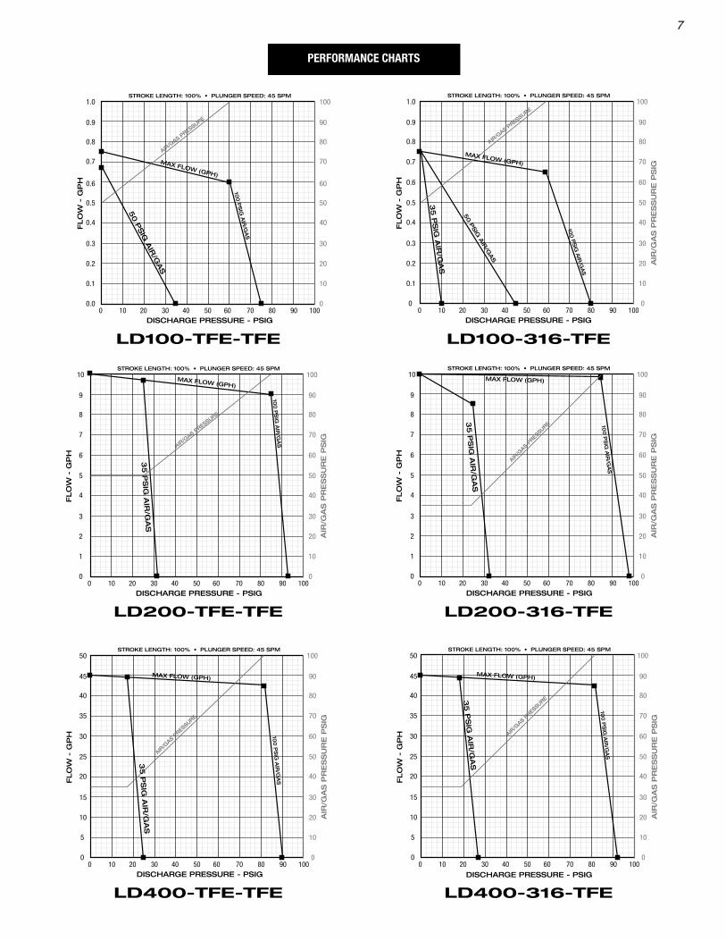
Refer to the performance charts on thefollowing page for the exact air/gaspressure.
3.1.2.3Use the controller’s rate adjustment andthe pump’s stroke length adjustment toobtain the desired flow rate for yourapplication. Use a pump rate setting gauge to set the flow or use a graduated flask orbeaker to time the flow rate with a stopwatch. (Refer to Section 1.3, SpecificationsTable, on page 4 for maximum pumpperformance.)
3.1.2.4The controller is preset at the factory toprovide 45 strokes per minute maximum.This value will fall on the 100 mark, sincethe scale is only used for a reference.However, at ZERO on the scale thecontroller will have little or no output to thepump. The controller can be adjusted asnecessary to another maximum value.
SECTION 3.0:STARTUP, OPERATION, AND SHUTDOWN
While the procedures for startup, operationand shutdown/storage are easy to perform,following them carefully and correctly willimprove the performance and increase thelife of your pump.
3.1 STARTUP
3.1.1 Air/Gas Supply
3.1.1.1Make sure that the primary air/gas supply— a compressor, a tank of gas, or otherresource— is turned OFF.
3.1.1.2Set the pressure regulator to ZEROpressure.
3.1.2 Controller & Pumps
3.1.2.1Rotate the stroke rate knob on thecontroller clockwise(CW) to ZERO on thestroke rate reference scale.
3.1.2.2Turn ON the main air/gas supply to theregulator and adjust the regulator topressure 20 to 40 psi above the pumpdischarge pressure.
DIMENSIONS
MODEL A B C D E F G H J
LD100-TFE 7.10 5.88 1.66 1/4”NPTM 1/4”NPTM 2.50 2.50 1.13 5.53
LD100-316 7.35 5.72 1.52 1/4”NPTM 1/4”NPTM 2.50 2.50 1.13 5.53
LD200-TFE 7.75 6.45 1.25 1/2” NPTM 1/2” NPTM 2.50 2.50 1.13 6.10
LD200-316 7.85 6.12 1.90 1/2” NPTM 1/2” NPTM 2.50 2.50 1.13 6.10
LD400-TFE 10.32 8.32 2.72 3/4” NPTM 3/4” NPTM 2.50 2.50 1.50 8.00
LD400-316 10.60 8.12 2.45 3/4” NPTM 3/4” NPTM 2.50 2.50 1.50 8.00
0 10 20 30 40 50 60 70 80 90 100
0.9
1.0
0.8
0.7
0.6
0.5
0.4
0.3
0.2
0.1
0.0
90
100
80
70
60
50
40
30
20
10
0
FLO
W -
GP
H
STROKE LENGTH: 100% • PLUNGER SPEED: 45 SPM
AIR
/GA
SP
RE
SS
UR
EP
SIG
100
PS
IG A
IR/G
AS
50 P
SIG
AIR
/GAS
AIR/G
AS PRESSURE
DISCHARGE PRESSURE - PSIG
MAX FLOW (GPH)
LD100-TFE-TFE
0 10 20 30 40 50 60 70 80 90 100
90
100
80
70
60
50
40
30
20
10
0
0.9
1.0
0.8
0.7
0.6
0.5
0.4
0.3
0.2
0.1
0
FLO
W -
GP
H
STROKE LENGTH: 100% • PLUNGER SPEED: 45 SPM
DISCHARGE PRESSURE - PSIG
AIR
/GA
S P
RE
SS
UR
E P
SIG
100 P
SIG
AIR
/GA
SAIR
/GAS P
RESSURE
35
PS
IG A
IR/G
AS
50 P
SIG
AIR
/GAS
MAX FLOW (GPH)
LD100-316-TFE
7
0 10 20 30 40 50 60 70 80 90 100
9
10
8
7
6
5
4
3
2
1
0
90
100
80
70
60
50
40
30
20
10
0
FLO
W -
GP
H
STROKE LENGTH: 100% • PLUNGER SPEED: 45 SPM
AIR
/GA
S P
RE
SS
UR
E P
SIG
100
PS
IG A
IR/G
AS
AIR/G
AS PRESSURE
35
PS
IG A
IR/G
AS
DISCHARGE PRESSURE - PSIG
MAX FLOW (GPH)
LD200-TFE-TFE
0 10 20 30 40 50 60 70 80 90 100
9
10
8
7
6
5
4
3
2
1
0
90
100
80
70
60
50
40
30
20
10
0
FLO
W -
GP
H
STROKE LENGTH: 100% • PLUNGER SPEED: 45 SPM
AIR
/GA
S P
RE
SS
UR
E P
SIG
100
PS
IG A
IR/G
AS
AIR/G
AS PRES
SURE
35
PS
IG A
IR/G
AS
DISCHARGE PRESSURE - PSIG
MAX FLOW (GPH)
LD200-316-TFE
0 10 20 30 40 50 60 70 80 90 100
45
50
40
35
30
25
20
15
10
5
0
90
100
80
70
60
50
40
30
20
10
0
FLO
W -
GP
H
STROKE LENGTH: 100% • PLUNGER SPEED: 45 SPM
AIR
/GA
S P
RE
SS
UR
E P
SIG
100
PS
IG A
IR/G
AS
AIR/G
AS PRESSURE
35
PS
IG A
IR/G
AS
DISCHARGE PRESSURE - PSIG
MAX FLOW (GPH)
LD400-TFE-TFE
0 10 20 30 40 50 60 70 80 90 100
45
50
40
35
30
25
20
15
10
5
0
90
100
80
70
60
50
40
30
20
10
0
FLO
W -
GP
H
STROKE LENGTH: 100% • PLUNGER SPEED: 45 SPMA
IR/G
AS
PR
ES
SU
RE
PS
IG
100
PS
IG A
IR/G
AS
AIR/G
AS PRESSURE3
5 P
SIG
AIR
/GA
S
DISCHARGE PRESSURE - PSIG
MAX FLOW (GPH)
LD400-316-TFE
PERFORMANCE CHARTS

8
3.1.2.5To adjust the controller stroke rate knob,loosen the set screw and remove the knoband spring. Adjust the valve stem with yourfingers to the desired rate. Turn the stemclockwise (CW) to decrease the stroke rateor counterclockwise (CCW) to increase therate. Attach and set the knob at the desiredposition on the scale or at the 100 mark.To do so, install spring and knob on stem.Press down on the knob until springpressure is felt, tighten set screw andreseal with latex paint.
3.1.2.6The pump’s stroke length adjuster scale isfactory set so that a ZERO reading equalszero stroke length. To calibrate the scale:
• Turn the stroke length adjuster knobCW until it bottoms the diaphragminside the pump.
• Loosen the Allen screw (3/32” hex) onthe end of the knob. Remove the knob.
• Rotate the cylinder until ZERO on thescale lines up with the scale indicatorVee notch on the pump body.
• Retighten set screw and replace knob. • Tighten Allen screw against flat on
shaft.
The stroke length can now be selectedfrom zero to 100% in 10% increments.
3.2.1Set the stroke rate knob to a mark on thescale that will produce the flow rate closeto what you want on the controller. A goodaverage speed is 25 - 35 SPM. Measurethe flow. Repeat and adjust as necessary.Lock stroke length with thumb screw.
NOTE: The Stroke Rate Scale on thecontroller is only a reference. At theZERO setting on the scale the pump willnot stroke, but as the knob is rotatedtoward 100, the rate will increase tomaximum of 45 strokes per minute.Since the scale is meant as a reference,you must time the exhaust of thecontroller in order to accurately set thestroke rate. Record this value andstroke length.
3.2.2For best accuracy, count the number ofpump strokes in a one minute interval. Ashort quick way is to count the strokes in15 second intervals and multiply by 4.
3.3 SHUTDOWN/STORAGE
3.3.1Set the pressure regulator to ZERO andturn the air/gas supply to the OFF position.
3.3.2.If you want to store the pump, flush out thepump chamber with a solvent or water,and blow dry with compressed air.
CAUTION: To avoid damaging the pumpwhen you clean it, make sure you use asolvent compatible with the meteredfluid that will not damage thediaphragm in the pump. For arecommended solvent, contact yourdistributor or Williams Instrument.
3.3.3You may leave the pump and controllerassembled. Be sure to store them in a dry,protected place.
3.1.2.7After the desired setting has been made,the wing thumb screw can be used to lockthe adjustment. For extreme vibrationconditions the black plastic wing can bebroken off and a 5/32 hex wrench may beused to further tighten screw.
NOTE: The stroke length is notproportional to pump flow. Controllerrate is proportional to flow.
3.2 OPERATION
Open all service valves. Apply air tocontroller. Confirm air pressure. Shortlyafter the pump begins to operate, themetered liquid should begin to flow throughthe pump. The pump is self priming. If thesupply reservoir is below the inlet valve(suction lift) and a foot valve is in thesuction line, it will take a few seconds forthe liquid flow to begin. Without a footvalve, it will take longer for the flow tostart. Once you have set the speed andstroke according to the procedure above,operation of both the controller and pumpis automatic and continuous at the strokerate as long as the pressure regulatormaintains a constant air/gas supplypressure.
DISCHARGECHECK VALVE
FACE PLATE
DIAPHRAGM
SUCTIONCHECK VALVE
STROKEADJUSTERRETURN
SPRING
MOTORCHAMBER
MOUNTINGBRACKET
STROKERATE KNOB
THUMBSCREWSTROKE ADJUSTER
9
SECTION 4.0MAINTENANCE
This section provides procedures fordisassembly and reassembly of thecontroller and the pump as well as thosefor preventive and corrective maintenance.Easy to perform, these procedures areessential to the reliability, durability, andperformance for your pump.
4.1 DISASSEMBLY AND ASSEMBLY
When you remove air/gas or process fluidpiping, be sure to cover the open ports inboth the controller and the pump to keepout dirt.
4.1.1 Required Tools(Tools differ according to the pump model.)
• Adjustable Wrench: 15”• Adjustable Wrench: 8”• Vise with soft jaws and vee notch• Hex Wrenches: 3/32”, 5/32”, 1/4”,
3/8”, and 1/2”• Blade Screwdriver: 1/8”• MK-X Screwdriver (Part No. WIC-
TOOL-I) with 1/4” Hex Socket Drivecontaining special lower seatspanner tool
• Open End Wrenches
4.1.2 Controllers4.1.2.1 Mark XII Controller DisassemblyRefer to the Mark XII Controller Parts List.To disassemble, do the following:
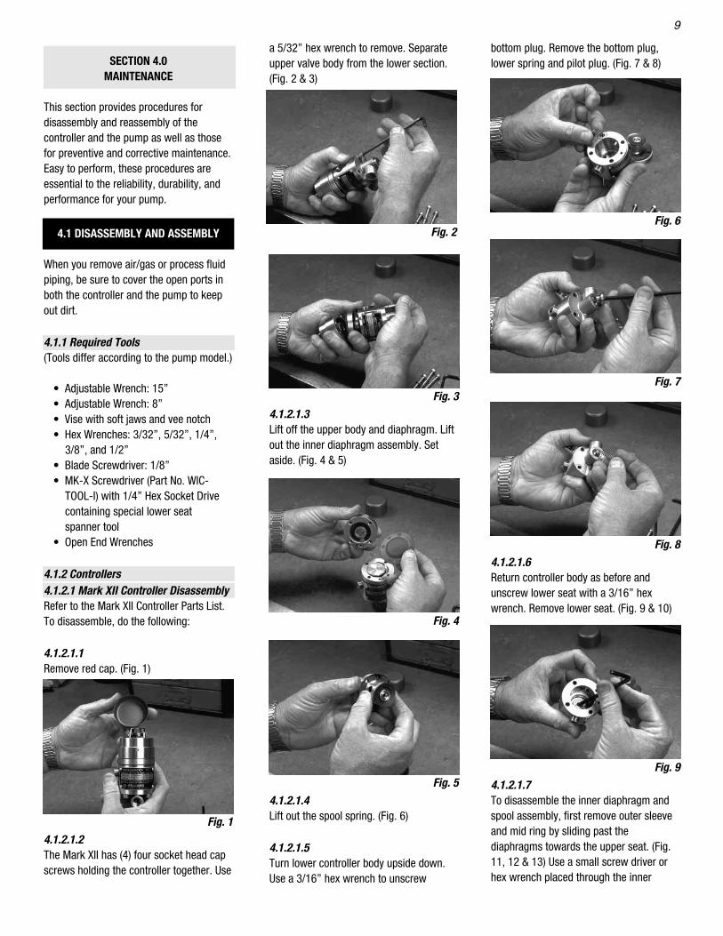
4.1.2.1.1Remove red cap. (Fig. 1)
4.1.2.1.2The Mark XII has (4) four socket head capscrews holding the controller together. Use
a 5/32” hex wrench to remove. Separateupper valve body from the lower section.(Fig. 2 & 3)
4.1.2.1.3Lift off the upper body and diaphragm. Liftout the inner diaphragm assembly. Setaside. (Fig. 4 & 5)
4.1.2.1.4Lift out the spool spring. (Fig. 6)
4.1.2.1.5Turn lower controller body upside down.Use a 3/16” hex wrench to unscrew
bottom plug. Remove the bottom plug,lower spring and pilot plug. (Fig. 7 & 8)
4.1.2.1.6 Return controller body as before andunscrew lower seat with a 3/16” hexwrench. Remove lower seat. (Fig. 9 & 10)
4.1.2.1.7To disassemble the inner diaphragm andspool assembly, first remove outer sleeveand mid ring by sliding past thediaphragms towards the upper seat. (Fig.11, 12 & 13) Use a small screw driver orhex wrench placed through the inner
Fig. 2
Fig. 3
Fig. 4
Fig. 5
Fig. 1
Fig. 6
Fig. 7
Fig. 8
Fig. 9

10
spacer holes and with a 9/16” wrenchunscrew the upper seat and lowerdiaphragm. (Fig. 14) Place the topdiaphragm stop (and inner sleeve withscrew driver/hex wrench) into a soft jawvice with a vee notch. Lightly clamp topdiaphragm stop. Unscrew inner sleeve.(Fig. 15) Remove the mid diaphragm fromthe top diaphragm stop. (Fig. 16) Removethe lower diaphragm from the upper seat.(Fig. 18)
4.1.2.1.9To install the inner assembly into the lowercontroller body, be sure to reinstall thelower seat and spool spring. Make sure thecapillary holes in the upper diaphragm, themid ring and the mid diaphragm are in linewith the capillary hole of the lower body.Use a small awl or hex wrench to threadtogether. Install (1) one of the (4) bodyscrews from the under side through theloose parts and through the topdiaphragm. Now remove the awl and placeon top of the assembly the upper controllerbody. Insure its capillary hole is inline withthe others. Loosely thread together the (1)one body screw. Install remaining (3) threescrews and torque all to 28 - 32 inchpounds.
4.1.2.2 Mark X Controller DisassemblyRefer to the MK-X Controller Parts List.To disassemble the controller, do thefollowing:
4.1.2.1.8Clean all metal parts. Inspect and orreplace all three diaphragms. Toreassemble, push the mid diaphragm ontothe top diaphragm stop. Push the lowerdiaphragm onto the upper seat. Thread theinner spacer onto these (2) two diaphragmassemblies. With a screw driver and 9/10”wrench, tighten securely, but not enoughto pucker the diaphragms. Install the midring, counter bore first, onto the diaphragmassembly past the lower diaphragm andthen past the mid diaphragm. Somemaneuvering of the diaphragms will beneeded. Install the outer sleeve by slidingpast the lower diaphragm. Insure thenarrow seat on the sleeve goes against themid diaphragm and the wider seat isagainst the lower diaphragm. Somemaneuvering of the lower diaphragm willalso be needed. The inner assembly is nowcomplete. (Fig. 17 & 19)
Fig. 10
Fig. 15
Fig. 16
Fig. 14
Fig. 11
Fig. 12
Fig. 13
Fig. 17
Fig. 18
Fig. 19

11
4.1.2.2.1Clamp the lower end of the controller bodyin a bench vise. (Fig. 20) Use soft jaws tohold controller. Remove red cap.
4.1.2.2.2Use an adjustable wrench on the flats atthe top of the valve body assembly;unscrew and pull off the upper valve bodyassembly. (Fig.21)
4.1.2.2.3Lift out the spool, with the three attachedU-cups and the spool alignment O-ring.(Fig.22)
4.1.2.2.4Lift out the spool spring. (Fig.23)
above procedure. Also, when necessary,refer to Section 2.0: Installation of Pumpand Controller.
4.1.3 PumpRefer to the appropriate pump parts listand drawing. For all pumps, first removethe controller and pipe nipple. The checkvalve removal can be done more easilyafter the face plate is removed from thepump.
Check Valve 316SS TFEWrench size Models Models
LD 100 - 9/16” 9/16” 5/8”LD 200 - 3/4” 7/8” 1 1/16”LD 400 - 7/8” 1 1/8” 1 1/4”
To disassemble your pump, follow theapplicable procedure below:
4.1.3.1 LD 100 SeriesNOTE: Photos shown are of the LD200-316 Model. The LD100-316 model issimilar in construction.
4.1.3.1.1Use a 5/32” hex wrench to remove the sixscrews and washers that fasten the backplate, spring housing and pump stand.Separate the pump stand and springhousing from the back plate and faceplate. (Fig. 28, 29, 30)
4.1.2.2.5Using the proper spanner-type bladescrewdriver (Part No. WIC-TOOL-1) for theMK-X, unscrew the lower seat and remove.(Fig.24 & 25)
4.1.2.2.6Lift out the pilot plug and exhaust spring.(Fig. 26)
4.1.2.2.7Remove the body O-ring that isolates thecontrol passage. (Fig. 27)Clean all parts. Inspect. Replace alldamage parts, seals and o-rings.To reassemble the controller, reverse the Fig. 28
Fig. 29
Fig. 20
Fig. 21
Fig. 24
Fig. 25
Fig. 26
Fig. 27
Fig. 22
Fig. 23
12
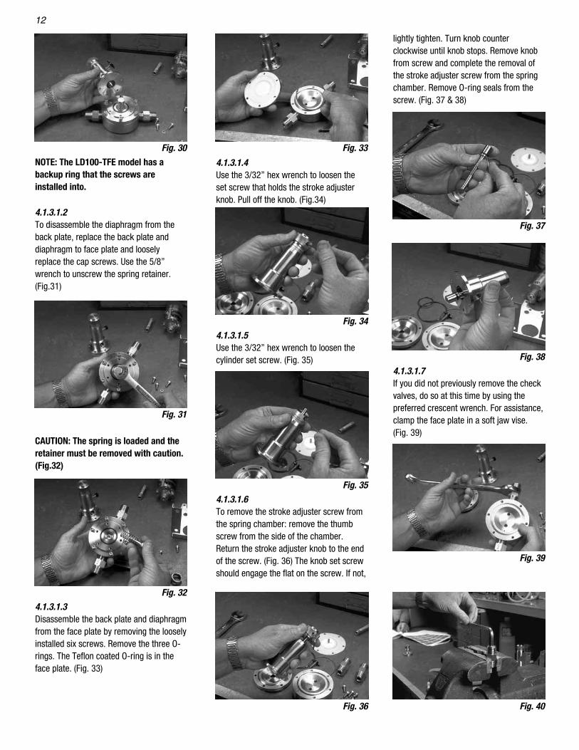
NOTE: The LD100-TFE model has abackup ring that the screws areinstalled into.
4.1.3.1.2To disassemble the diaphragm from theback plate, replace the back plate anddiaphragm to face plate and looselyreplace the cap screws. Use the 5/8”wrench to unscrew the spring retainer.(Fig.31)
CAUTION: The spring is loaded and theretainer must be removed with caution.(Fig.32)
4.1.3.1.3Disassemble the back plate and diaphragmfrom the face plate by removing the looselyinstalled six screws. Remove the three O-rings. The Teflon coated O-ring is in theface plate. (Fig. 33)
lightly tighten. Turn knob counterclockwise until knob stops. Remove knobfrom screw and complete the removal ofthe stroke adjuster screw from the springchamber. Remove O-ring seals from thescrew. (Fig. 37 & 38)
4.1.3.1.7If you did not previously remove the checkvalves, do so at this time by using the preferred crescent wrench. For assistance,clamp the face plate in a soft jaw vise.(Fig. 39)
4.1.3.1.4Use the 3/32” hex wrench to loosen theset screw that holds the stroke adjusterknob. Pull off the knob. (Fig.34)
4.1.3.1.5Use the 3/32” hex wrench to loosen thecylinder set screw. (Fig. 35)
4.1.3.1.6To remove the stroke adjuster screw fromthe spring chamber: remove the thumbscrew from the side of the chamber.Return the stroke adjuster knob to the endof the screw. (Fig. 36) The knob set screwshould engage the flat on the screw. If not,
Fig. 30
Fig. 31
Fig. 33
Fig. 34
Fig. 35
Fig. 36
Fig. 37
Fig. 38
Fig. 39
Fig. 32
Fig. 40

13
4.1.3.2.8.3For the LD 200 - TFE models, use the 3/8”hex wrench to remove the retainer. Inspectseat area for damage or imbedded dirt.Replace as necessary. (Fig. 42 & 43)
4.1.3.2.8.4When reassembling check valves back onto the pump, note the flow direction arrowon the check valves. The suction checkvalve arrow points into the pump. Thedischarge arrow points away from thepump.
4.1.3.3 LD 400 SeriesNOTE: Photos shown are of the LD200-316 model. The LD400-316 is similar inconstruction.
4.1.3.3.1Use the 5/32” Allen wrench to remove the(6) six screws that fasten the springchamber and pump stand to the backplate. Separate the components. (Fig. 28,29, 30)
4.1.3.3.2Place the back plate and face plateassembly, name plate side down. Using a3/4” wrench, unscrew the spring retainerscrew. (Fig. 31)
CAUTION: The spring is loaded and theretainer must be removed with caution.Remove the spring retainer anddiaphragm return spring. (Fig. 32)
4.1.3.3.3Use the 5/32” hex wrench to remove the(8) eight screws that fasten the back plateto the face plate. Separate thecomponents. Remove the (3) three O-rings. The coated O-ring is removed fromthe face plate. (Fig. 33)
NOTE: The LD400-TFE Model has aBackup Ring that the screws areinstalled into.
4.1.3.3.4 To disassemble the stroke adjustermechanism, remove the wing thumbscrew.
and face plate assembly, name plate sidedown. Using a 5/8” wrench, unscrew thespring retainer screw. (Fig. 31)
CAUTION: The spring is loaded and theretainer must be removed with caution.Remove the spring retainer screw anddiaphragm return spring. (Fig. 32)
4.1.3.2.3Disassembly of the back plate anddiaphragm from the face plate requiresremoval of the (6) six screws. Use the5/32” hex wrench. Separate thecomponents. Remove (3) O-rings. Thecoated O-ring is removed from the faceplate. (Fig. 33)
NOTE: The LD 200-TFE has a BackupRing that the screws are installed into.
4.1.3.2.4Use the 3/32” hex wrench to loosen theset screw that holds the stroke adjusterknob. Pull off the knob. (Fig. 34)
4.1.3.2.5Use the 3/32” hex wrench to loosen thecylinder set screw. (Fig. 35)
4.1.3.2.6To remove the stroke adjuster screw fromthe spring chamber, follow the instructionsof paragraph 4.1.3.1.6.
4.1.3.2.7If you did not previously remove the checkvalves, do so at this time by using a 7/8”wrench. For assistance, clamp the faceplate in a soft jaw vise. (Fig. 39)
4.1.3.2.8 When rebuilding check valves 4.1.3.2.8.1Clamp the check valve in the soft jaw viseand use a 3/8” hex wrench to unscrew theretainer. (Fig. 40)
4.1.3.2.8.2Remove the ball sleeve with Teflon O-ringand inspect ball and seat area for damage.Replace the Teflon O-ring and all damagedparts. (Fig. 41)
4.1.3.1.8 When rebuilding check valves4.1.3.1.8.1Clamp check valve in a soft jaw vise anduse a 3/16” hex wrench to unscrew theretainer. (Fig. 40)
4.1.3.1.8.2Remove the ball and sleeve with Teflonseat. Inspect for damage. (Fig. 41)4.1.3.1.8.3Remove the Teflon O-ring and replace alldamaged parts. (Fig. 41)
4.1.3.1.8.4For the LD 100 - TFE model, inspect theseat area for damage. Replace if damagedor imbedded with dirt. Inspect check valvesealing ring. (Fig. 42)
4.1.3.1.8.5When reassembling, note the flowdirection arrow on the check valves. Thesuction check valve points into the pump.The discharge arrow points away from thepump.
4.1.3.2 LD 200 SeriesUse the 5/32” hex wrench to remove thesix screws that fasten the spring chamberand pump stand from the back plate.Separate the components. (Fig. 28, 29 &30)
4.1.3.2.2To disassemble the spring retainer screwfrom the diaphragm, place the back plate
Fig. 41
Fig. 42

14
WILLIAM INSTRUMENT, INC. will repair or replace any pump due to defects in material or workmanship for a period of up to twelve months from
the date of shipment. Product failure due to any other reason including, but not limited to misuse, negligence, accident, normal wear and usage,
or improper installation and operation, will not be remedied under this warranty. This warranty is valid only if the repairs are performed by
WILLIAMS INSTRUMENT, INC. and returned to the factory for inspection (freight prepaid) within the warranty period. No claim for labor or
consequential damages will be allowed.
SECTION 5.0
LIMITED WARRANTY
4.1.3.3.9.2For the LD400-TFE models, use the 1/2”hex wrench to remove the retainer. Inspectthe seat area for damage or imbedded dirt.Replace parts as necessary. (Fig. 42 & 43)
4.1.3.3.9.3When reassembling, note the flowdirection arrow on the check valves. Thesuction check valve points into the pump.The discharge arrow points away from thepump. To reassemble your pump, reversethe applicable disassembly procedures.
4.2 PREVENTIVE MAINTENANCE
4.2.1 Periodic Maintenance Schedule4.2.1.1At least every 6 months, inspect the pumpdiaphragm. If it is cracked, rough, ordiscolored, replace it.
4.1.3.3.5Use the 3/32” hex wrench to loosen theset screw that holds the stroke adjusterknob. Pull off the knob. (Fig. 34)
4.1.3.3.6Use the 3/32” hex wrench to loosen thecylinder set screw.
4.1.3.3.7To remove the stroke adjuster screw fromthe spring chamber, follow the instructionsin paragraph 4.1.3.1.6.
4.1.3.3.8If you did not previously remove the checkvalves, do so at this time by using the1 1/8” wrench. For assistance, clamp theface plate in a soft jaw vise. (Fig. 39)
4.1.3.3.9 When Rebuilding Check Valve4.1.3.3.9.1For the LD 400 - 316 model, clamp thecheck valve in the soft jaw vise. With a1/2” hex wrench remove the retainer balland sleeve. Inspect the ball and Teflon O-ring for damage. Replace the Teflon O-ringand all damaged parts. (Fig. 40 & 41)
4.2.1.2At least every 12 months, disassemble andinspect the pump inlet and outlet checkvalves.
4.2.1.3At least every 12 months, inspect thepump diaphragm return spring. If it iscracked, chipped, or flaking, replace it.
4.2.1.4At least every 12 months, replace the MK Xcontroller spool U-cups. If a MK XII is used,replace the three diaphragms.
4.2.2 Cleaning and LubricationWhen pump is disassembled, clean allinterior and exterior surfaces with a goodquality solvent, and blow dry with highpressure air.
CAUTION: Make sure to use a solvent forcleaning that is correct for the processfluid and will not damage the seals inyour pump. Contact your distributor orWilliams Instrument for arecommended solvent.
Use silicone grease to lubricate all seals,O-rings and other surfaces that create aseal or have sliding contact with anothersurface. Request our G321M1 or G321M4(1 oz. or 4 oz. container) for this purpose.
Fig. 43
15
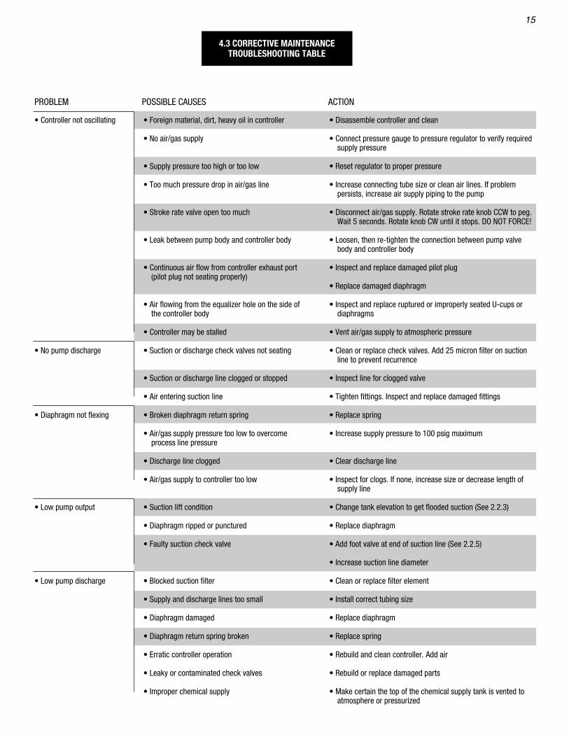
• Controller not oscillating
• No pump discharge
• Diaphragm not flexing
• Low pump output
• Low pump discharge
• Foreign material, dirt, heavy oil in controller
• No air/gas supply
• Supply pressure too high or too low
• Too much pressure drop in air/gas line
• Stroke rate valve open too much
• Leak between pump body and controller body
• Continuous air flow from controller exhaust port(pilot plug not seating properly)
• Air flowing from the equalizer hole on the side ofthe controller body
• Controller may be stalled
• Suction or discharge check valves not seating
• Suction or discharge line clogged or stopped
• Air entering suction line
• Broken diaphragm return spring
• Air/gas supply pressure too low to overcomeprocess line pressure
• Discharge line clogged
• Air/gas supply to controller too low
• Suction lift condition
• Diaphragm ripped or punctured
• Faulty suction check valve
• Blocked suction filter
• Supply and discharge lines too small
• Diaphragm damaged
• Diaphragm return spring broken
• Erratic controller operation
• Leaky or contaminated check valves
• Improper chemical supply
• Disassemble controller and clean
• Connect pressure gauge to pressure regulator to verify requiredsupply pressure
• Reset regulator to proper pressure
• Increase connecting tube size or clean air lines. If problempersists, increase air supply piping to the pump
• Disconnect air/gas supply. Rotate stroke rate knob CCW to peg.Wait 5 seconds. Rotate knob CW until it stops. DO NOT FORCE!
• Loosen, then re-tighten the connection between pump valvebody and controller body
• Inspect and replace damaged pilot plug
• Replace damaged diaphragm
• Inspect and replace ruptured or improperly seated U-cups ordiaphragms
• Vent air/gas supply to atmospheric pressure
• Clean or replace check valves. Add 25 micron filter on suctionline to prevent recurrence
• Inspect line for clogged valve
• Tighten fittings. Inspect and replace damaged fittings
• Replace spring
• Increase supply pressure to 100 psig maximum
• Clear discharge line
• Inspect for clogs. If none, increase size or decrease length ofsupply line
• Change tank elevation to get flooded suction (See 2.2.3)
• Replace diaphragm
• Add foot valve at end of suction line (See 2.2.5)
• Increase suction line diameter
• Clean or replace filter element
• Install correct tubing size
• Replace diaphragm
• Replace spring
• Rebuild and clean controller. Add air
• Rebuild or replace damaged parts
• Make certain the top of the chemical supply tank is vented toatmosphere or pressurized
4.3 CORRECTIVE MAINTENANCETROUBLESHOOTING TABLE
PROBLEM POSSIBLE CAUSES ACTION


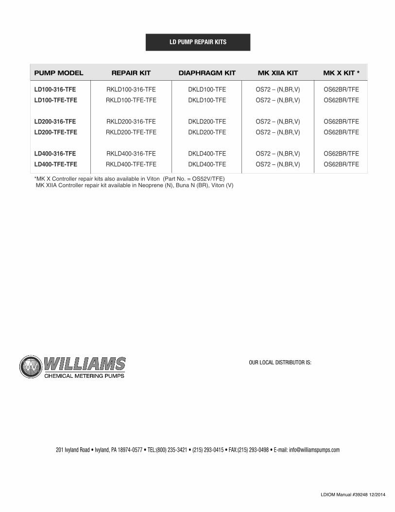
201 Ivyland Road • Ivyland, PA 18974-0577 • TEL:(800) 235-3421 • (215) 293-0415 • FAX:(215) 293-0498 • E-mail: [email protected]
OUR LOCAL DISTRIBUTOR IS:
PUMP MODEL REPAIR KIT DIAPHRAGM KIT MK XIIA KIT MK X KIT *
LD100-316-TFE RKLD100-316-TFE DKLD100-TFE OS72 – (N,BR,V) OS62BR/TFE
LD100-TFE-TFE RKLD100-TFE-TFE DKLD100-TFE OS72 – (N,BR,V) OS62BR/TFE
LD200-316-TFE RKLD200-316-TFE DKLD200-TFE OS72 – (N,BR,V) OS62BR/TFE
LD200-TFE-TFE RKLD200-TFE-TFE DKLD200-TFE OS72 – (N,BR,V) OS62BR/TFE
LD400-316-TFE RKLD400-316-TFE DKLD400-TFE OS72 – (N,BR,V) OS62BR/TFE
LD400-TFE-TFE RKLD400-TFE-TFE DKLD400-TFE OS72 – (N,BR,V) OS62BR/TFE
*MK X Controller repair kits also available in Viton (Part No. = OS52V/TFE)MK XIIA Controller repair kit available in Neoprene (N), Buna N (BR), Viton (V)
LD PUMP REPAIR KITS
LDIOM Manual #39248 12/2014
Related Documents


