RLE TECHNOLOGIES LD1500 USER GUIDE

Welcome message from author
This document is posted to help you gain knowledge. Please leave a comment to let me know what you think about it! Share it to your friends and learn new things together.
Transcript

RLE TECHNOLOGIES
LD1500 USER GUIDE

©2009 RLE Technologies 110068 Rev 1.0 (1/2009)

LD1500

©2008 RLE Technologies 110068 Rev 1.0 (1/2009)
PRODUCT REGISTRATION
Product registration helps RLE Technologies inform owners of:
Product Upgrades Firmware Enhancements New Products and Technologies Special Offers Available Only to Registered Users
Submit registration information on the Support/Product Registration webpage at www.rletech.com.
**Any information provided to RLE Technologies through the registration form will be regarded as confidential. RLE will not
sell or distribute any of the information to third parties. To read our Privacy Policy, please visit our website: www.rletech.com**
TECHNICAL SUPPORT
Personal assistance is available Monday through Friday, from 8:00 a.m. to 5:00 p.m. MST.
For more information, please download the Product User Guide located on the Products/LD5100 section on our website at www.rletech.com,
A request for assistance may be sent to [email protected].
Otherwise, please call us directly at: (970) 484-6510 - press “2” for technical support
The following information is located on the bottom of each LD1500 unit. Please have this information available whenever a technical support call is placed:
Product Model Number _____________________________________________________
Product Serial Number _____________________________________________________
Product Manufacture Date ___________________________________________________

User Guide: LD1500 Table of Contents
www.rletech.com 970 484-6510 i
TABLE OF CONTENTS Chapter 1: Product Overview ........................................................................................................................................1
1-1 Description ......................................................................................................................................................1
1-2 Operation.........................................................................................................................................................1
1-3 Mechanical Description...................................................................................................................................1
1-4 Installation.......................................................................................................................................................1
1-5 Reference map.................................................................................................................................................1
1-6 Web Interface..................................................................................................................................................2
Chapter 2: Connections and Settings.............................................................................................................................3
2-1 Connections.....................................................................................................................................................3
Chapter 3: Installation ...................................................................................................................................................5
3-1 Installing the Unit............................................................................................................................................5
3-2 Connecting the Water Leak Detection Cable ..................................................................................................5
3-3 Apply Power to the Unit .................................................................................................................................7
3-4 Communication...............................................................................................................................................7
Chapter 4: Webpage Interface .......................................................................................................................................9
4-1 Home/Main Menu ...........................................................................................................................................9
4-2 Cable status .....................................................................................................................................................9
4-3 Alarm Log .....................................................................................................................................................10
4-4 Firmware .......................................................................................................................................................10
4-5 Configuration ................................................................................................................................................11
Chapter 5: Modbus Communication............................................................................................................................18
5-1 Implementation Basics ..................................................................................................................................18
5-2 Packet Communications for the LD1500 ......................................................................................................19
5-3 RTU Framing ................................................................................................................................................21
Appendix A: Updating Firmware ................................................................................................................................22
A-1 Updating the Flash Firmware via web interface/tftp .....................................................................................22
Appendix B: Preventive Maintenance .........................................................................................................................23
Appendix C: Troubleshooting .....................................................................................................................................24
Appendix D: Technical Specifications ........................................................................................................................26

List of Figures and Tables User Guide: LD1500
ii 970 484-6510 www.rletech.com
LIST OF FIGURES AND TABLES
Figure 2-1: LD1500 Connections ................................................................................................................................. 3
Figure 3-1: Water Leak Detection Cable (SC).............................................................................................................. 5
Figure 3-2: Cable Installation Methods ........................................................................................................................ 6
Figure 4-1: LD1500 Log In Page.................................................................................................................................. 9
Figure 4-2: Home Page................................................................................................................................................. 9
Figure 4-3:Cable Status .............................................................................................................................................. 10
Figure 4-4: Alarm Log Page ....................................................................................................................................... 10
Figure 4-5: Firmware Page ......................................................................................................................................... 10
Figure 4-6: Configuration Menu................................................................................................................................. 11
Figure 4-7: Leak Configuration Page ......................................................................................................................... 12
Figure 4-8: Web Configuration................................................................................................................................... 12
Figure 4-9: Network/IP Settings ................................................................................................................................. 12
Figure 4-10: SNMP Configuration Page..................................................................................................................... 13
Figure 4-11: SNMP/Syslog Communities Configuration ........................................................................................... 14
Figure 4-12: SNMP Trap Test .................................................................................................................................... 14
Figure 4-13: Modbus/EIA-485 Configuration Page ................................................................................................... 15
Figure 4-14: BACnet Configuration ........................................................................................................................... 15
Figure 4-15: BACnet BDT Configuration .................................................................................................................. 16
Figure 4-16: BACnet Alarm ....................................................................................................................................... 16
Figure 4-17: System Management Page ..................................................................................................................... 17
Figure 4-18: Exit to Bootloader Page ......................................................................................................................... 17
Table 1: Exception Codes ........................................................................................................................................... 18
Table 2: Read Output Registers Packet Structure ....................................................................................................... 19
Table 3: Output Registers ........................................................................................................................................... 19
Table 4: Read Input Registers Packet Structure.......................................................................................................... 20
Table 5: Input Registers.............................................................................................................................................. 20
Table 6: Status Flags (Register 30001):...................................................................................................................... 20
Table 7: Preset Single Register Packet Structure........................................................................................................ 20
Table 8: Preset Multiple Registers Packet Structure................................................................................................... 21
Table 9: Response Sample.......................................................................................................................................... 21

User Guide: LD1500 Chapter 1: Product Overview
www.rletech.com 970 484-6510 1
CHAPTER 1: PRODUCT OVERVIEW
1-1 DESCRIPTION The LD1500 is a complete monitoring system that detects and reports the presence of water and other conductive liquids. The LD1500 couples SeaHawk Leak Detection Cable (SC) with an advanced control panel. Each LD1500 monitors up to 1500 feet (457.2m) of SC cable. When a conductive liquid comes in contact with the SC cable, an Alarm LED is illuminated red on the front panel, the distance to the leak is shown on the LD1500’s webpage, and alarm notifications are distributed via user-configurable Modbus (EIA-485 RTU or TCP/IP), BACnet (EIA-485 MS/TP or IP), or SNMP.
1-2 OPERATION When the LD1500’s analog circuitry measures a current in excess of the user-defined leak threshold, the unit’s microprocessor computes the distance to the leak. The unit then annunciates the leak and logs the alarm in its event log. The LD1500 provides a webpage interface to allow users to get updates on the unit’s conditions via the Internet or local area network. The LD1500 also provides Modbus and BACnet outputs via EIA-485, twisted-pair wire or TCP/IP.
The LD1500 is a supervised system—it continually monitors the cable for continuity. A cable break or excess contamination of the cable causes an Alarm indication and notification.
1-3 MECHANICAL DESCRIPTION The LD1500 is built with one circuit board: The main board is mounted inside of the enclosure.
1-4 INSTALLATION The LD1500 is a wall mounted device. Before applying power to the unit, ensure that all connections are correct and all screw terminals are secure. The LD1500 is powered by 24 VAC or 24 VDC power. DO NOT connect 115/230 VAC to the unit; damage will occur to the circuitry.
1-5 REFERENCE MAP Users are advised to purchase a framed reference map (FM1114) for use with the LD1500 to aid in locating any detected leaks along the SC cable; to view sample maps, go to the SeaHawk Accessories webpage at www.rletech.com. Once all the SC cable is installed, compare this reference map with the actual cable installation. Note any discrepancies and return the map to the original author for correction. Keep a copy for use until the map is revised.
NOTE: The LD1500 produces an alarm in the following conditions:
Leak Detected
Cable Break (or Cable Fault)
Cable Contamination
Loss of Communications

Chapter 1: Product Overview User Guide: LD1500
2 970 484-6510 www.rletech.com
1-6 WEB INTERFACE The LD1500’s webpage interface provides remote information updates via network communications. The interface’s menu structure is as follows: Home
Alarm Status Model sysUpTime
Cable Status Self-test
Alarm Log Firmware Configuration Menu
Leak Settings Web Settings Network/IP Settings SNMP SNMP/Syslog Community 1 SNMP/Syslog Community 2 SNMP Trap Test
o Send Test Trap – Leak Detected o Send Test Trap – Cable Break o Send Test Trap - Contamination
Modbus/EIA-485 o Modbus Slave Register Display
BACnet o BACnet Information
BACnet BDT BACnet Alarm System Management
o Exit to Bootloader o Restore Factory Defaults
A more detailed description of the webpage interface can be found in Chapter 4: Webpage Interface, beginning on page 9.

User Guide: LD1500 Chapter 2: Connections and Settings
www.rletech.com 970 484-6510 3
CHAPTER 2: CONNECTIONS AND SETTINGS
The LD1500 is comprised of one board. All connections are accessible when the unit is inside of its enclosure. The connectors on the main board, found at the bottom of the following photograph, are labeled TB1 through TB3 and P1 through P4.
P1 TB1Power
TB2Cable
Interface
P2RJ45
SW1 TB3EIA-485
P4EIA-232
Craft Port
Figure 2-1: LD1500 Connections
2-1 CONNECTIONS
2-1.1 P1: Input Power This is an optional barrel connection for input power (as you may also use TB1 for input power) with the following connection:
Inside positive (+) Outside negative (-)
Power is recommended to be supplied by a 24VDC wall adapter power supply (part #WA-DC-24), which is not included with the LD1500 and can be purchased separately. For more information on RLE power supplies, visit the Falcon Accessories webpage at www.rletech.com, or contact RLE.
2-1.2 TB1: Input Power This is an optional two position connector (as you may also use P1 for input power) with the following connections:
TB1-1 24VDC positive (+) TB1-2 24VDC negative (-)
Chapter 2: Connections and Settings User Guide: LD1500
4 970 484-6510 www.rletech.com
Polarity suggestions are optional, as the LD1500 power inputs are connected directly to an internal bridge rectifier. 24VAC uses the same power connector as 24VDC.
2-1.3 TB2: Cable Interface The SeaHawk Water Leak Detection Cable (SC) connects to TB2. A 15 foot (4.57m) non-sensing leader cable is required (included in a leader cable kit: part #LC-KIT) to connect the LD1500 to the SC cable. Connect the cable wires to TB2 as follows:
TB2-1 White wire TB2-2 Black wire TB2-3 Green wire TB2-4 Red wire
2-1.4 P2: RJ45 Network A 10/100 Ethernet connection is available to connect the LD1500 on a local area network. Use a crossover cable for initial connection and configuration. The default settings are as follows:
IP Address: 10.0.0.188 Subnet Mask: 255.255.255.0
2-1.5 SW1.1: Ethernet Port Configuration Switch SW1.1, when switched DOWN, enables 10/100BASE-T Auto Negotiate. When switched UP, it locks the Ethernet port in 100BASE-T. Auto Negotiate does not work with some gigabit switches; therefore, the LD1500 ships with switch SW1.1 in the UP, 100BASE-T locked, position.
2-1.6 SW1.2:EIA-485 Termination Switch SW1.2, when switched ON (DOWN), places a termination resistor across the + and – terminals of the EIA-485 port. This is used when the LD1500 is the last unit on an EIA-485 network.
2-1.7 TB3: EIA-485 Modbus Port TB4 connects to an EIA-485 network. A grounded shield contact is provided for connection to shielded cable. If the shield contact is used, verify the power connector is properly grounded and there is no voltage potential between units on the network. The EIA-485 port is set to 8 data bits, no parity, and 1 stop bit (8, N, 1). Connect the EIA-485 wires to TB4 as follows:
TB3-1 A (+) TB3-2 B (-) TB3-3 Shield
2-1.8 P4: EIA-232 Connector The EIA-232 uses a baud rate of 9600. The EIA-232 port is set to 8 data bits, no parity, and 1 stop bit (8, N, 1). A straight through cable should be used to connect a terminal or PC to the LD1500. This connection should only be used for Setting of the IP address, advanced diagnostics, firmware uploading, and troubleshooting only.

User Guide: LD1500 Chapter 3: Installation
www.rletech.com 970 484-6510 5
CHAPTER 3: INSTALLATION
3-1 INSTALLING THE UNIT The LD1500 is a wall mounted device. There are four mounting holes on the sides of the unit spaced 6.6 inches (.167m) apart. Use drywall anchors if securing the unit to drywall.
3-2 CONNECTING THE WATER LEAK DETECTION CABLE The LD1500 requires a leader cable (included in the leader cable kit: part #LC-KIT). One end of this leader cable connects into the LD1500. This end of the cable has four stripped, bare wires. The other end features a mating connector which connects with the SeaHawk Water Leak Detection Cable (SC). The end of the cable is finished with a removable End-of-Line terminator (EOL).
Connect the 15 foot (4.57m) leader cable to the LD1500. From left to right, with the screws of the terminal block connector facing up, the wires that screw into the terminal connector should be colored: white, black, green, and red. If the terminal connector is removed from the end of the cable, make sure the wires are in this same order when the connector is reapplied. Once the leader cable is plugged into the terminal block, it is ready to be connected to the SC cable. To do this, unscrew the EOL from the end of the leader cable. Attach the first length of SC cable to the leader cable. Route the SC cable according to a cable layout diagram, if provided. Lay the cable according to the following guidelines on the next page. Secure the EOL on the unoccupied end of the SC cable.
Figure 3-1: Water Leak Detection Cable (SC)
NOTE: A Leader Cable Kit (part #LC-KIT) is required to connect the LD1500 to SeaHawk
Water Leak Detection Cable (SC). The kits are not included with the LD1500 and can be purchased separately.

Chapter 3: Installation User Guide: LD1500
6 970 484-6510 www.rletech.com
3-2.1 Securing Cable to the Floor Secure the SC cable to the floor with either J-clips (part #JC), or one of the other approved methods shown in Figure 3.2. J-clips (part #JC), available from RLE and designed specifically for use with SC cable, are the manufacturer’s recommended installation method and can be installed as follows:
Place one J-clip every 3 feet (.914m) along the length of the SC cable and one at each turn of the cable.
If the cable is installed over an obstruction, place a J-clip on the cable on both sides, as close to the obstruction as possible.
Do not install the cable directly in front of an air conditioner. Allow a minimum of 6 feet (1.83m) between the unit and the cable. If the cable is too close to the air conditioning unit’s air stream, the moisture from the humidifier may cause false leak readings. If the cable must be installed in front of an air conditioning unit, place the J-clips 12 to 18 inches (.305m to .457m) apart.
Figure 3-2: Cable Installation Methods
NOTE:
It is important to finish the end of the SeaHawk Water Leak Detection Cable (SC) with the end terminator (EOL). If the EOL terminator is not present, a cable fault will register. Note any variances between the cable layout diagram and the actual cable installation.

User Guide: LD1500 Chapter 3: Installation
www.rletech.com 970 484-6510 7
3-3 APPLY POWER TO THE UNIT Once the SeaHawk Water Leak Detection Cable (SC) is connected to the unit, power may be applied. The LD1500 operates on 24VDC or 24VAC power. RLE recommends that power be supplied by a 24VDC wall adapter power supply (part #WA-DC-24).
A power supply should be run to the location of the unit. Before applying power to the unit, ensure all cable and communication connections are complete. The LD1500 should begin booting upon power. Wait approximately one minute. No alarm should be present. On the webpage interface, under the Cable Status link, the cable length is displayed. If this reading varies by more than ±5% of the actual length of cable installed, verify the installation. The LD1500 should not require any calibration. If any calibration is required, verify that the cable current is 0 (zero) before calibrating or false and inaccurate readings will occur. Set the system name, alarm configuration, feet/meters, etc., through the webpage submenus.
3-4 COMMUNICATION The LD1500 will not communicate over a user’s network the first time it is connected to the network. The manufacturer programs the LD1500 with a default IP address: 10.0.0.188, subnet: 255.255.255.0 and gateway (Def Route): 10.0.0.1. These settings must be changed to IP addresses that correspond with the user’s network before the LD1500 can communicate over the network.
3-4.1 Set the LD1500’s IP Address
Via the Web browser
Via the EIA-232 interface
3-4.1.1 Set the LD1500’s IP Address Using a Web Browser
1. Plug the crossover network cable that shipped with the LD1500 unit into the laptop or workstation that will be used to configure the LD1500. This cable is not intended to be connected to a network hub.
2. Write down the computer’s IP address and Subnet Mask. Then change the IP address and Subnet Mask of the computer from its existing address to one that will allow it to communicate with the LD1500, such as 10.0.0.190. It may be beneficial to set the IP address to one that is one number different from the Falcon’s IP address. Consult the computer’s manual or your IT Department before attempting this.
3. Connect the other end of the network cable to the Ethernet port on the LD1500. Access the LD1500 through a Web browser by typing the IP address into the location bar. Enter the LD1500 user name and password when prompted.
NOTE:
A power supply is not included with the LD1500. The recommended 24VDC power supply (part #WA-DC-24) can be purchased separately. For more information on RLE power supplies, visit the Falcon Accessories webpage at www.rletech.com, or contact RLE.
NOTE:
The default user name is “ld1500” (use all lower case, as user name is case sensitive). There is no default password - leave the password field empty.

Chapter 3: Installation User Guide: LD1500
8 970 484-6510 www.rletech.com
4. Select the Configuration Menu link, then select the Network Settings link. Change the IP address, Subnet Mask, and Def Route to ones provided by the network administrator. Press the Submit Changes button. The LD1500 will save the new IP address and reboot. You must now use the new IP address and reset your computer to its original IP address and Subnet Mask.
5. Change the IP address of your computer back to its original IP address. If the computer was configured as DHCP (the network domain controller assigns an IP address) return it to this state. This may require assistance from your IT Department, or you may need to consult the computer’s manual.
6. The computer and the LD1500 are now both configured to communicate on the network. Both should be accessible via the network. Connect the PC and the LD1500 to the network. From the PC Web browser, type in the IP address of the LD1500. Enter the user name and password as stated above to verify network access to the LD1500.
3-4.1.2 Set the LD1500’s IP Address using an EIA-232 Connection
To use the EIA-232 interface:
1. Connect the EIA-232 port (P4) on the LD1500 to a terminal or PC running terminal emulation software (such as HyperTerminal) with a 9-pin male-female straight through serial cable.
2. Set the appropriate communication port to 9600 baud, 8 data bits, no parity, 1 stop bit (9600/N/8/1), and no software or hardware flow command.
3. Once the terminal emulation software starts, type ? and press ENTER on the keyboard and the Main Menu should appear. If the Main Menu does not appear, check the communication settings and make sure the unit is powered on.
4. From the Main Menu type “netcfg” to select the Network Configuration Menu.
5. Enter the new IP address for the LD1500 by typing ip xxx.xxx.xxx.xxx where xxx.xxx.xxx.xxx is the new IP address of the unit. Separate each field with a decimal point – for example type ip 10.0.0.50 <enter>.
6. The LD1500 will erase a memory block and copy data to Flash memory before rebooting.
7. The LD1500 IP address is now set and the LD1500 can be accessed through a Web browser using the new IP address.
8. Repeat steps 4-7 to change the Subnet Mask and Def Route, if needed, using the commands nm xxx.xxx.xxx.xxx to change the Subnet Mask and dg xxx.xxx.xxx.xxx to change the default gateway.

User Guide: LD1500 Chapter 4: Webpage Interface
www.rletech.com 970 484-6510 9
CHAPTER 4: WEBPAGE INTERFACE The LD1500’s network connection allows users to configure and view current information from the LD1500. When logging on to the LD1500, navigate to the unit’s IP address in a Web browser. A prompt will ask for a username and password. Enter in the appropriate information.
Default Settings: IP: 10.0.0.188 Username: ld1500 Password: -none/blank-
Figure 4-1: LD1500 Log In Page
4-1 HOME/MAIN MENU When logging into the LD1500, the first page display is the Home page. All vital information is displayed in the main table. From the main page, four links are available in the bottom left section: Cable Status, Alarm Log, Firmware, and Configuration Menu.
Figure 4-2: Home Page
4-2 CABLE STATUS The Cable Status page displays a table of System Alarm Status, Cable Length, Current, Leg Resistances and Alarm Delay Counts. A link to a self-test diagnostic is also available on this page. The diagnostic will connect internal precision 4.02K test resistors into the leak detection circuitry and display the results: leg resistances, zero leakage and full leakage test, and near and far leak calculations.

Chapter 4: Webpage Interface User Guide: LD1500
10 970 484-6510 www.rletech.com
Figure 4-3:Cable Status
4-3 ALARM LOG The Alarm Log page displays a table of Alarm History. The Alarm History table displays Alarms and events recorded in the unit’s memory log of the last 10 events. The alarms are displayed as follows:
TYPE – SYSTEM_TIME_STAMP DESCRIPTION SYSTEM_TIME_STAMP is displayed as xxd HH:MM:SS format since the system was
powered up where xxd = days, HH=hours (01-24), MM=minutes (01-60) and SS=seconds (01-60).
DESCRIPTION provides details about the current alarm/event (e.g. Leak, Cable Fault, etc.).
Figure 4-4: Alarm Log Page
4-4 FIRMWARE The Firmware page displays the Flash application name, version and size in bytes, and the Bootloader name and version.
Figure 4-5: Firmware Page

User Guide: LD1500 Chapter 4: Webpage Interface
www.rletech.com 970 484-6510 11
4-5 CONFIGURATION The Configuration page gives access to a menu of available settings.
Figure 4-6: Configuration Menu
4-5.1 Leak Settings The Leak Settings menu displays all current leak and cable settings.
Leak Trip Point: The amount of current leakage required to detect a leak. Default setting is 150uA. Adjust this
number to adjust the sensitivity of the leak detection cable to leaks (higher = less sensitive, lower = more sensitive).
Contamination Trip Point: The amount of current leakage required to detect cable contamination. Default
setting is 50uA. Adjust this number to adjust the sensitivity of the leak detection cable to contamination (higher = less sensitive, lower = more sensitive).
Leak Alarm Delay: The amount of time required to pass once the Leak Trip Point has been reached
before declaring a leak alarm. Default setting is 20 seconds. The Leak Trip Point must be exceeded for the duration of the delay.
Contamination Alarm Delay: The amount of time required to pass once the Contamination Trip Point
has been reached before declaring a contamination alarm. Default setting is 120 seconds. The Contamination Trip Point must be exceeded for the duration of the delay.
Resistance Per Foot: The resistance per foot (or meter) of cable determines the unit’s ability to
accurately detect the (SC) cable length installed and calculate distances to leaks. The default setting is 2.800 ohms and should not be changed for any RLE cable; parts SC-10, SC-25, SC-50, and SC-100 are all built to specifications of 2.8 ohms per foot.
Measurement Display: Select either feet or meters to calibrate the LD1500 to the preferred unit of
measure.

Chapter 4: Webpage Interface User Guide: LD1500
12 970 484-6510 www.rletech.com
Figure 4-7: Leak Configuration Page
4-5.2 Web Settings The Web Settings menu allows users to set two different security level passwords on the LD1500. A Read-Only level password allows users to only view the information and settings of the LD1500. No settings or changes may be submitted to the unit. The Read/Write level password allows users to change settings and configurations on the LD1500 as well as view all information in the unit. The Web refresh rate changes the interval that the Home page refreshes automatically when left open in an Internet browser.
Figure 4-8: Web Configuration
4-5.3 Network/IP Settings The Network settings allow users to change the network configuration of the LD1500. IP address, Subnet Mask, and Default Route (Gateway) may be changed from this menu.
Figure 4-9: Network/IP Settings

User Guide: LD1500 Chapter 4: Webpage Interface
www.rletech.com 970 484-6510 13
4-5.4 SNMP The SNMP Configuration page allows users to configure SNMP notification options. See definitions below: System Name: Appears on the LD1500 Main Menu and is included as part of email notifications. System Contact: Lists the individual responsible for the LD1500. The System Contact is only available through SNMP Gets and is not included in email or SNMP Trap notifications. System Location: Lists the location of the LD1500. The System Location is not included in email or SNMP Trap notifications. SNMP Trap Type: Selects the type of trap/inform (V1 or V2C) that the LD1500 will send for SNMP Trap notifications. Max Inform Retries: Specifies the number of times the LD1500 will attempt to send an Inform. An entry of zero (0) means that the LD1500 will attempt to send the Inform indefinitely.
Inform Interval: Specifies the interval in minutes between Inform attempts.
Figure 4-10: SNMP Configuration Page
4-5.5 SNMP/Syslog Communities 1 & 2 The SNMP/Syslog Communities Configuration pages identify devices that receive SNMP Traps and/or Syslog messages from the LD1500 and interact with the LD1500 over the network. To add a device to the Communities list, select a community number posted as “empty”. Enter the receiving device’s IP Address and a string that identifies the device. An IP Address of 0.0.0.0 in this field allows any device to access the LD1500 through an MIB browser. Select “Write” if the device will have Read/Write network access. This allows the LD1500 to be configured over the network. Select “Traps” if the device will receive Traps from the LD1500. Select “Syslog” if the device will receive Syslog messages from the LD1500.

Chapter 4: Webpage Interface User Guide: LD1500
14 970 484-6510 www.rletech.com
Figure 4-11: SNMP/Syslog Communities Configuration
4-5.6 SNMP Trap Test The SNMP Trap Test page contains three pushbuttons that allow the user to send SNMP Traps out the Ethernet port, simulating an alarm event. Pushbuttons are available for Leak Detected, Cable Break, and Contamination.
Figure 4-12: SNMP Trap Test
4-5.7 Modbus The Modbus/EIA-485 Configuration page allows users to configure Modbus (EIA-485 and/or TCP/IP) options. See definitions below: Modbus/TCP/UDP Slave Unit Identifier: Specify the slave address used on the LD1500’s IP port (1-254). Select EIA-485 Port Function: Sets the EIA-485 port for Modbus-Slave or BACnet MS/TP-Slave. EIA-485 Slave Address: Set the EIA-485 Port’s slave address (1-254). Each device on the EIA-485 Modbus network must have a unique address. EIA-485 Baud Rate: Sets the EIA-485 Port to 1200, 2400, 9600 or 19,200 Baud. All the devices connected to the Modbus network must be set to operate at the same Baud rate. EIA-485 Parity: Sets the EIA-485 Port to None, Even or Odd Parity. All the devices connected to the Modbus network must be set to operate at the same parity. Modbus Slave Register Display: Displays the contents of the Modbus Slave Registers. See Table 3 on page 19 and Table 5 on page 20 for descriptions of the register contents.

User Guide: LD1500 Chapter 4: Webpage Interface
www.rletech.com 970 484-6510 15
Figure 4-13: Modbus/EIA-485 Configuration Page
4-5.8 BACnet The BACnet Configuration page allows the user to enable the LD1500 for BACnet slave configuration.
BACnet Device Name: The name of the LD1500 as it will appear on the BACnet network BACnet Device ID: The unique identifier for the LD1500 on the BACnet network BACnet Description: The description of the LD1500 as it will appear on the BACnet network BACnet UDP Port: The port to which the LD1500 will respond to BACnet requests. The default number of zero in this field will configure the LD1500 to listen on the standard BACnet port of 47808, see the BACnet standard for more information. BACnet Information: Displays the status of the BACnet interface, including Alarm flag status, BACnet Objects, BACnet Property Identifiers, and BACnet Device Objects.
Figure 4-14: BACnet Configuration
4-5.9 BACnet BDT The BACnet BDT Configuration page allows the user to review and edit the BACnet Broadcast Distribution Table. The following information is given on the webpage.

Chapter 4: Webpage Interface User Guide: LD1500
16 970 484-6510 www.rletech.com
BACnet BBMD-BDT, LD1500 IP Address #1 IP Address, Port, Mask
#2 IP Address, Port, Mask
#3 IP Address, Port, Mask
#4 IP Address, Port, Mask These fields DO NOT need to be configured by the user. If the LD1500 is acting as a BACnet router, these fields will automatically be populated by the BACnet network controller.
Figure 4-15: BACnet BDT Configuration
4-5.10 BACnet Alarm The BACnet Alarm Configuration page allows the user to configure the BACnet alarm settings.
Recipient #1 IP Address, PID
Notification Type: Unconfirmed or Confirmed
Notification Class, Priority
Leak Detected Alarms: Analog or Binary
APDU Timeout: in seconds
Number of APDU retries
Figure 4-16: BACnet Alarm
4-5.11 System Management The System Management page allows users to restore the unit to factory default settings and upload firmware.

User Guide: LD1500 Chapter 4: Webpage Interface
www.rletech.com 970 484-6510 17
Figure 4-17: System Management Page
Exit to Bootloader: Forces the unit to stop running flash application to allow for firmware updates; for more information see Appendix A: Updating Firmware on page 22. Restore Factory Defaults: Resets the configuration and settings on the unit to all factory defaults.
Figure 4-18: Exit to Bootloader Page

Chapter 5: Modbus Communication User Guide: LD1500
18 970 484-6510 www.rletech.com
CHAPTER 5:MODBUS COMMUNICATION This document describes the Modbus communications protocol as supported by the LD1500 Distance Read System. It includes details and information on how to configure the LD1500 for communications via Modbus network.
5-1 IMPLEMENTATION BASICS The LD1500 is capable of communicating via the half-duplex EIA-485 serial communication standard. The LD1500 is configured to act as a slave device on a common network. The EIA-485 medium allows for multiple devices on a multi-drop network. The LD1500 is a slave only device and will never initiate a communications sequence.
5-1.1 Modes of Transmission The Modbus protocol uses ASCII and RTU modes of transmission. The LD1500 supports only the RTU mode of transmission, with 8 data bits, no parity and 1 stop bit. Every Modbus packet consists of four fields: Slave Address Field Function Field Data Field Error Check Field (Checksum)
5-1.1.1 Slave Address Field
The slave address field is one byte in length and identifies the slave device involved in the transaction. The valid address range is between 1 and 254. The slave address is set from the Modbus/EIA-485 Configuration webpage (see section 4-5.7 Modbus, pg. 14).
5-1.1.2 Function Field
The function field is one byte in length and tells the LD1500 which function to perform. The supported functions are 03 (Read 4xxxx output registers), 04 (Read 3xxxx input registers), 06 (Preset single register) and 16 (Preset multiple registers).
5-1.1.3 Data Field
The data field of the request is a variable length depending on the function. The data fields for the LD1500 are 16-bit registers, transmitted high order byte first (big-endian).
5-1.1.4 Error Check (Checksum) Field
The checksum field lets the receiving device determine if the packet has transmission errors. The LD1500 RTU mode uses a 16-bit cyclic redundancy check (CRC-16).
5-1.2 Exception Responses If a Modbus master sends an invalid command to the LD1500 or attempts to read an invalid register, an exception response is generated. The response packet will have the high order bit of the function code set to one. The data field of the exception response contains the exception error code.
Table 1: Exception Codes
Code Name Description 01 Illegal Function The function code is not supported 02 Illegal Data Address Attempt to access an invalid address 03 Illegal Data Value Attempt to set a variable to an invalid value

User Guide: LD1500 Chapter 5: Modbus Communication
www.rletech.com 970 484-6510 19
5-2 PACKET COMMUNICATIONS FOR THE LD1500
5-2.1 Function 03: Read Output Registers To read the LD1500 parameter values, the master must send a Read Output Registers request packet.
The Read Output Registers request packet specifies a start register and the number of registers to read. The start register is numbered from zero (40001 = zero, 40002 = one, etc).
Table 2: Read Output Registers Packet Structure
Read Registers Request Packet Read Registers Response Packet Slave Address (1 byte) Slave Address (1 byte) 03 (Function code) (1 byte) 03 (Function code) (1 byte) Start Register (2 bytes) Byte count (1 byte) # of registers to read (2 bytes) First register (2 bytes) CRC Checksum (2 bytes) Second register (2 bytes) … CRC Checksum (2 bytes)
Table 3: Output Registers
Register Name Description Range, Units Range 40001 Leak Threshold Trip current for leak alarm 25-295 uAmps 0-65535 40002 Contamination Threshold Trip current for contamination alarm 20-295 uAmps 0-65535 40003 Spare 0-65535 40004 Spare 0-65535 40005 Spare 0-65535 40006 Spare 0-65535 40007 Spare 0-65535 40008 Spare 0-65535 40009 Spare 0-65535 40010 Spare 0-65535 40011 Spare 0-65535 40012 Spare 0-65535 40013 Spare 0-65535 40014 Spare 0-65535 40015 Spare 0-65535 40016 Leak Alarm Delay Leak Alarm Delay 5-995 seconds 0-65535 40017 Contamination Alarm Delay Contamination Alarm Delay 5-995 seconds 0-65535
5-2.2 Function 04: Read Input Registers To read the LD1500 input values, the master must send a Read Input Registers request packet. The Read Input Registers request packet specifies a start register and the number of registers to read. The start register is numbered from zero (30001 = zero, 30002 = one, etc).

Chapter 5: Modbus Communication User Guide: LD1500
20 970 484-6510 www.rletech.com
Table 4: Read Input Registers Packet Structure
Read Registers Request Packet Read Registers Response Packet Slave Address (1 byte) Slave Address (1 byte) 04 (Function code) (1 byte) 04 (Function code) (1 byte) Start Register (2 bytes) Byte count (1 byte) # of registers to read (2 bytes) First register (2 bytes) CRC Checksum (2 bytes) Second register (2 bytes) … CRC Checksum (2 bytes)
Table 5: Input Registers
Register Name Description Units Range 30001 Status Bit Level Status None 0-65535 30002 Leak Distance Location of Leak Ft/Meters 0-65535 30003 Units Unit of Measure 1=Ft 0=Meters 0-65535 30004 Leak Current Leakage current on cable uAmps 0-65535 30005 Cable Length Installed Cable Length Ft/Meters 0-65535 30006 Loop1 Res Resistance of cable Ohms 0-65535 30007 Loop2 Res Resistance of cable Ohms 0-65535 30008 Res/Ft Resistance of cable Ohms x1000 0-65535 30009 Version Firmware version xx.xx X 100 0-65535
Table 6: Status Flags (Register 30001):
Bit Description 00 1 = Leak is Detected 01 1 = Cable Break Alarm 02 1 = Contamination is detected 03 1 = Summary Alarm 04-15 Spare
5-2.3 Function 06: Preset Single Register To set a LD1500 parameter value, the master must send a Preset Single Register request packet. The Preset Single Register request packet specifies a register and the data to write to that register. The register is numbered from zero (40001 = zero, 40002 = one, etc).
Table 7: Preset Single Register Packet Structure
Preset Register Request Packet Preset Register Response Packet Slave Address (1 byte) Slave Address (1 byte) 06 (Function code) (1 byte) 06 (Function code) (1 byte) Register (2 bytes) Register (2 byte) Data (2 bytes) Data (2 bytes) CRC Checksum (2 bytes) CRC Checksum (2 bytes)
User Guide: LD1500 Chapter 5: Modbus Communication
www.rletech.com 970 484-6510 21
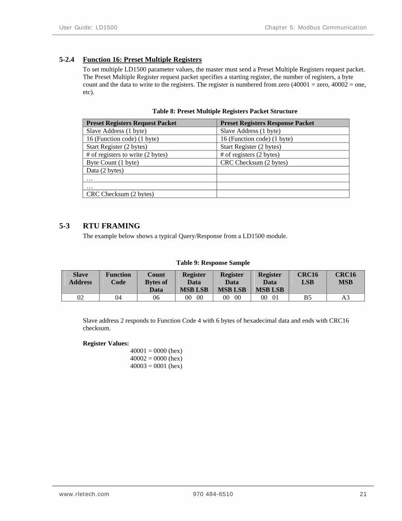
5-2.4 Function 16: Preset Multiple Registers To set multiple LD1500 parameter values, the master must send a Preset Multiple Registers request packet. The Preset Multiple Register request packet specifies a starting register, the number of registers, a byte count and the data to write to the registers. The register is numbered from zero (40001 = zero, 40002 = one, etc).
Table 8: Preset Multiple Registers Packet Structure
Preset Registers Request Packet Preset Registers Response Packet Slave Address (1 byte) Slave Address (1 byte) 16 (Function code) (1 byte) 16 (Function code) (1 byte) Start Register (2 bytes) Start Register (2 bytes) # of registers to write (2 bytes) # of registers (2 bytes) Byte Count (1 byte) CRC Checksum (2 bytes) Data (2 bytes) … … CRC Checksum (2 bytes)
5-3 RTU FRAMING The example below shows a typical Query/Response from a LD1500 module.
Table 9: Response Sample
Slave Address
Function Code
Count Bytes of
Data
Register Data
MSB LSB
Register Data
MSB LSB
Register Data
MSB LSB
CRC16 LSB
CRC16 MSB
02 04 06 00 00 00 00 00 01 B5 A3 Slave address 2 responds to Function Code 4 with 6 bytes of hexadecimal data and ends with CRC16
checksum.
Register Values: 40001 = 0000 (hex) 40002 = 0000 (hex) 40003 = 0001 (hex)
Appendix A: Updating Firmware User Guide: LD1500
22 970 484-6510 www.rletech.com
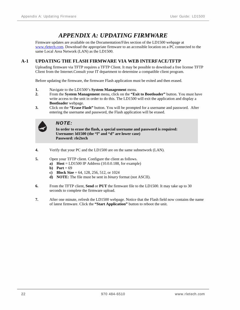
APPENDIX A: UPDATING FIRMWARE Firmware updates are available on the Documentation/Files section of the LD1500 webpage at www.rletech.com. Download the appropriate firmware to an accessible location on a PC connected to the same Local Area Network (LAN) as the LD1500.
A-1 UPDATING THE FLASH FIRMWARE VIA WEB INTERFACE/TFTP Uploading firmware via TFTP requires a TFTP Client. It may be possible to download a free license TFTP Client from the Internet.Consult your IT department to determine a compatible client program. Before updating the firmware, the firmware Flash application must be exited and then erased.
1. Navigate to the LD1500’s System Management menu. 2. From the System Management menu, click on the “Exit to Bootloader” button. You must have
write access to the unit in order to do this. The LD1500 will exit the application and display a Bootloader webpage.
3. Click on the “Erase Flash” button. You will be prompted for a username and password. After entering the username and password, the Flash application will be erased.
4. Verify that your PC and the LD1500 are on the same subnetwork (LAN).
5. Open your TFTP client. Configure the client as follows.
a) Host = LD1500 IP Address (10.0.0.188, for example) b) Port = 69 c) Block Size = 64, 128, 256, 512, or 1024 d) NOTE: The file must be sent in binary format (not ASCII).
6. From the TFTP client, Send or PUT the firmware file to the LD1500. It may take up to 30
seconds to complete the firmware upload. 7. After one minute, refresh the LD1500 webpage. Notice that the Flash field now contains the name
of latest firmware. Click the “Start Application” button to reboot the unit.
NOTE:
In order to erase the flash, a special username and password is required: Username: ld1500 (the “l” and “d” are lower case) Password: rle2tech

User Guide: LD1500 Appendix B: Preventive Maintenance
www.rletech.com 970 484-6510 23
APPENDIX B: PREVENTIVE MAINTENANCE
Follow these steps monthly to test the system and ensure that the control panel is functioning properly:
1. Place water on the cable.
2. Verify the Leak Detected alarm through the Web interface or BMS.
3. Compare the distance reading on the LD1500 to a reference map (if available) to verify that the LD1500 displays the correct leak location.
4. Dry the cable and verify that the LD1500 returns to normal.
5. Remove the End-of-Line terminator (EOL).
6. Verify the Cable Break alarm through the Web interface.
7. Reinstall the EOL.
8. Verify that the LD1500 returns to normal.
Monitor the cable current monthly to verify that the cable is not being contaminated. The LD1500 will alarm on cable contamination if the contamination is excessive.
From the LD1500 Web interface, verify that the Cable Current is less than 25uA. If the cable current is greater than 25uA, it is recommended to troubleshoot the cables to determine which cable is contaminated. The contaminated cable should be removed, cleaned, retested and reinstalled.

Appendix C: Troubleshooting User Guide: LD1500
24 970 484-6510 www.rletech.com
APPENDIX C: TROUBLESHOOTING
Trouble Action
Control Panel will not Power Up
1. Check with a DVOM (multi-meter) for AC or DC input power on the lower left hand terminal block on the LD1500. If no voltage is present at terminal block, check the circuit (breaker) or power supply the LD1500 control panel is powered by. If voltage is present, go to step 2.
2. Contact RLE Technologies for unit replacement and/or evaluation. If voltage is present and no LEDs are illuminated, contact RLE Technologies for further troubleshooting.
Cable Break Alarm 1. Verify that the leader cable from the SeaHawk Water Leak Detection Cable (SC) run is plugged into terminal block marked “Cable”.
2. Verify that the End-of-Line terminator (EOL) is installed on the end of the orange SC cable run. If present at the end of the cable run, go to step 3.
3. Remove the EOL terminator from the end of the cable run and install it onto the end of the leader cable coming from the control panel. If the condition clears, there is a damaged/faulty section of SC cable. Start moving the EOL terminator to the end of each section of SC cable to isolate the faulty section. If the condition does not clear, go to step 4.
4. Power down (shut off) the control panel. Remove terminal block marked “Cable” from the unit. Remove the four conductors from the leader cable wire going into the four position terminal block. Install a jumper wire between pins 1 and 2 and another jumper wire between pins 3 and 4. Reinstall the terminal block back into TB2. If the cable break condition clears, there is a problem with the leader cable. If the condition does not clear, contact RLE Technologies for further support.
Control Panel not Calculating Proper Length of Cable
1. First verify the proper wiring order into terminal block marked “Cable”. Wiring color code should be as follows from left to right: white, black, green, and red.
2. Calibrate your cable. To do this, adjust the Resistance per Foot (Configuration menu via the Web Interface). If the condition does not change, please contact RLE Technologies. The control panel is pre-calibrated from the factory. The overall footage should be within 5% of actual installed length.

User Guide: LD1500 Appendix C: Troubleshooting
www.rletech.com 970 484-6510 25
Control Panel not Calculating Proper Leak Distance
1. Check the distance on the cable run to verify that the control panel is monitoring. Verify there is no water along the cable run. Check to see if multiple leaks are present on the cable. The first leak should be read and latched by the system; however, if the system is updated or simultaneous leaks occur (2 or more) within 30 seconds of the initial leak, the system may display the average distance (distance of the first leak + distance of the second leak / 2). If no water is present, go to step 2.
2. Power down (shut off) the control panel and remove the End-of-Line terminator (EOL) from the end of the SC cable. Locate the first section of SC cable from the LD1500 control panel. Where it joins to the second section of cable, disconnect and install the EOL terminator at the end of the first section of SC cable. Turn power back on at control panel. Once the control panel runs for five to ten minutes, use a damp cloth, rag or paper towel and place it on the end of the orange SC cable. If the leak is calculated correctly, remove the EOL terminator; reconnect the SC cable and move down to the next section of cable. Repeat this process until a faulty reading is obtained. If the reading is off at the first section of cable, there may be miscalculations from the LD1500 unit, please contact RLE Technologies for support.
Cable Contamination Alarm
1. To clear a contamination alarm, the cable must be removed and cleaned. Usually the cable can be cleaned by pulling it through a clean damp rag.
2. If the cable is contaminated by oil, glycol or chemicals, the cable can be washed. Use a mild detergent solution of 1 capful to 2 gallons lukewarm water (<105°F). Agitate the cable in a suitable container, rinse with clear lukewarm water and wipe dry with a clean towel. The cable may also be cleaned by wiping it down with Isopropyl Alcohol.
3. Retest the cable by connecting it to the LD1500 before reinstalling it under the floor.
NOTE:
Contamination and/or physical damage to the cable is not covered under warranty. For all other troubleshooting concerns and questions regarding this product, contact RLE Technologies.

Appendix D: Technical Specifications User Guide: LD1500
26 970 484-6510 www.rletech.com
APPENDIX D: TECHNICAL SPECIFICATIONS Power 24VAC Isolated @ 600mA max, 50/60Hz; requires power supply (not included)
24VDC@ 600mA max; requires power supply: WA-DC-24-ST (not included) Inputs Water Leak Detection Cable Cable Input
Compatible with SeaHawk SC Cable (not included) Requires SeaHawk LC-KIT: 15ft (4.57m) leader cable and EOL (LC-KIT not included)
Recommended Maximum Length 1,500ft (457.2m) Detection Accuracy ± 2ft (0.6m)+/- 0.5% of the cable length Detection Repeatability ± 2ft (0.6m) +/- 0.25% of the cable length Detection Response Time 5-995sec, software adjustable in 5sec increments; ±2sec Communications Ports Ethernet 10/100BASE-T, RJ45 connector; 500VAC RMS isolation EIA-232 DB9 female connector; 9600 baud; 8 data bits, no parity, 1 stop bit EIA-485 1200, 2400, 9600 or 19200 baud (selectable); Parity: none, even or odd, 8 data
bits, 1 stop bit Protocols TCP/IP, HTML, TFTP IPv4.0; webpages comply with Rehabilitation Act of 1973, sections 504 and 508,
US Dept of Education (website accessibility for computer users with disabilities) SNMP V1: V2C MIB-2 compliant; NMS Manageable with Get, Set, Trap/Inform Modbus (EIA-485) Slave; RTU Mode; Supports function codes 03, 04, 06 and 16 Modbus TCP/IP, UDP/IP Modbus Slave; TCP/IP, UDP/IP transmission protocol BACnet/IP Conformance Level 1 BACnet (EIA-485) Slave; MS/TP Terminal Emulation (EIA-232) VT100 compatible Alarm Notification Visual Alarm Bi-color status LED SNMP Traps (Ethernet) 2 Community Strings Logging Capabilities Event Log Last 10 events Login Security Web Browser Access (Ethernet) 1 Web password Read Only; 1 Web password Read/Write
Terminal Emulation Access None Front Panel Interface
LED Indicators Power/Status: 1 bi-color (Power On: green; Alarm / Cable Fault / Cable Contamination: red)
Operating Environment
Temperature 32° to 122°F (0° to 50°C) Humidity 5% to 95% RH, non-condensing Altitude 15,000ft (4,572m) max. Storage Environment -4° to 185°F (-20° to 85°C) Dimensions 7.075”W x 3.625”H x 1.25”D (179.7mmW x 92.07mmH x31.75mmD) Weight 1.5 lbs. (680g) Mounting Vertical wall mount Certifications CE; ETL listed: conforms to UL STD 61010-1, EN STD 61010-1; certified to
CSA C22.2 STD NO. 61010-1; RoHS compliant

FORT COLLINS CO 970 484-6510
970 484-6650 FAX WWW .RLETECH .COM
Related Documents