INSTALLATION AND OPERATION INSTRUCTIONS LCX-15MT TM WWW.LOWRANCE.COM

Welcome message from author
This document is posted to help you gain knowledge. Please leave a comment to let me know what you think about it! Share it to your friends and learn new things together.
Transcript

75
INSTALLATION ANDOPERATION INSTRUCTIONS
LCX-15MT
TM
WWW.LOWRANCE.COM
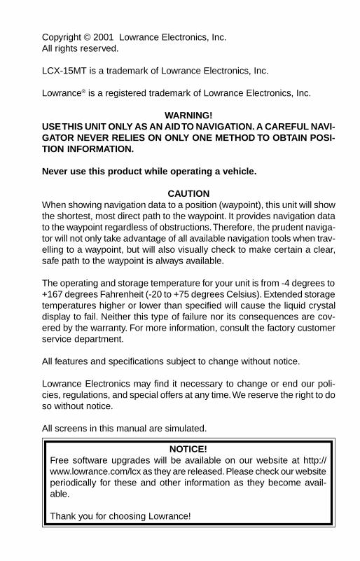
Copyright © 2001 Lowrance Electronics, Inc.All rights reserved.
LCX-15MT is a trademark of Lowrance Electronics, Inc.
Lowrance® is a registered trademark of Lowrance Electronics, Inc.
WARNING!USE THIS UNIT ONLY AS AN AID TO NAVIGATION. A CAREFUL NAVI-GATOR NEVER RELIES ON ONLY ONE METHOD TO OBTAIN POSI-TION INFORMATION.
Never use this product while operating a vehicle.
CAUTIONWhen showing navigation data to a position (waypoint), this unit will showthe shortest, most direct path to the waypoint. It provides navigation datato the waypoint regardless of obstructions. Therefore, the prudent naviga-tor will not only take advantage of all available navigation tools when trav-elling to a waypoint, but will also visually check to make certain a clear,safe path to the waypoint is always available.
The operating and storage temperature for your unit is from -4 degrees to+167 degrees Fahrenheit (-20 to +75 degrees Celsius). Extended storagetemperatures higher or lower than specified will cause the liquid crystaldisplay to fail. Neither this type of failure nor its consequences are cov-ered by the warranty. For more information, consult the factory customerservice department.
All features and specifications subject to change without notice.
Lowrance Electronics may find it necessary to change or end our poli-cies, regulations, and special offers at any time. We reserve the right to doso without notice.
All screens in this manual are simulated.
NOTICE!Free software upgrades will be available on our website at http://www.lowrance.com/lcx as they are released. Please check our websiteperiodically for these and other information as they become avail-able.
Thank you for choosing Lowrance!
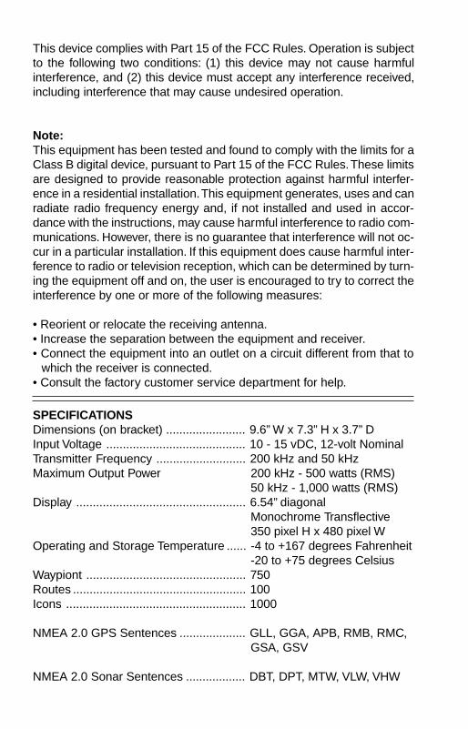
This device complies with Part 15 of the FCC Rules. Operation is subjectto the following two conditions: (1) this device may not cause harmfulinterference, and (2) this device must accept any interference received,including interference that may cause undesired operation.
Note:This equipment has been tested and found to comply with the limits for aClass B digital device, pursuant to Part 15 of the FCC Rules. These limitsare designed to provide reasonable protection against harmful interfer-ence in a residential installation. This equipment generates, uses and canradiate radio frequency energy and, if not installed and used in accor-dance with the instructions, may cause harmful interference to radio com-munications. However, there is no guarantee that interference will not oc-cur in a particular installation. If this equipment does cause harmful inter-ference to radio or television reception, which can be determined by turn-ing the equipment off and on, the user is encouraged to try to correct theinterference by one or more of the following measures:
• Reorient or relocate the receiving antenna.• Increase the separation between the equipment and receiver.• Connect the equipment into an outlet on a circuit different from that to
which the receiver is connected.• Consult the factory customer service department for help.
SPECIFICATIONSDimensions (on bracket) ........................ 9.6” W x 7.3” H x 3.7” DInput Voltage .......................................... 10 - 15 vDC, 12-volt NominalTransmitter Frequency ........................... 200 kHz and 50 kHzMaximum Output Power 200 kHz - 500 watts (RMS)
50 kHz - 1,000 watts (RMS)Display ................................................... 6.54” diagonal
Monochrome Transflective350 pixel H x 480 pixel W
Operating and Storage Temperature ...... -4 to +167 degrees Fahrenheit-20 to +75 degrees Celsius
Waypiont ................................................ 750Routes .................................................... 100Icons ...................................................... 1000
NMEA 2.0 GPS Sentences .................... GLL, GGA, APB, RMB, RMC,GSA, GSV
NMEA 2.0 Sonar Sentences .................. DBT, DPT, MTW, VLW, VHW
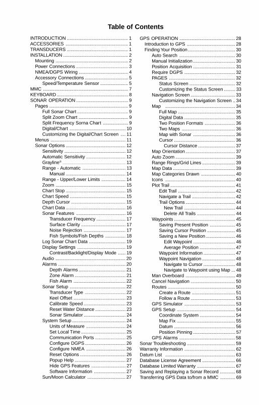
GPS OPERATION ............................................ 28Introduction to GPS ...................................... 28Finding Your Position ..................................... 30
Auto Search ............................................ 30Manual Initialization ................................. 30Position Acquisition ................................. 31Require DGPS ........................................ 32PAGES .................................................... 32
Status Screen .................................... 32Customizing the Status Screen ......... 33
Navigation Screen ................................... 33Customizing the Navigation Screen .. 34
Map ....................................................... 34Full Map ............................................. 35Digital Data ........................................ 35Two Position Formats ........................ 36Two Maps .......................................... 36Map with Sonar ................................. 36Cursor ................................................ 36
Cursor Distance ............................. 37Map Orientation ....................................... 37Auto Zoom ............................................... 39Range Rings/Grid Lines .......................... 39Map Data ................................................. 39Map Categories Drawn ........................... 40Icons ....................................................... 40Plot Trail ................................................... 41
Edit Trail ............................................. 42Navigate a Trail .................................. 42Trail Options ....................................... 44
New Trail ........................................ 44Delete All Trails .............................. 44
Waypoints ................................................ 45Saving Present Position .................... 45Saving Cursor Position ...................... 45Saving a New Position ....................... 46
Edit Waypoint ................................. 46Average Position ............................ 47
Waypoint Information ......................... 47Waypoint Navigation .......................... 48
Navigate to Cursor ......................... 48Navigate to Waypoint using Map ... 48
Man Overboard ....................................... 49Cancel Navigation ................................... 50Routes ..................................................... 50
Create a Route .................................. 51Follow a Route ................................... 53
GPS Simulator ........................................ 53GPS Setup .............................................. 54
Coordinate System ............................ 54Map Fix .............................................. 55Datum ................................................ 56Position Pinning ................................. 57
GPS Alarms ............................................ 58Sonar Troubleshooting ...................................... 59Warranty Information ........................................ 62Datum List ....................................................... 63Database License Agreement .......................... 66Database Limited Warranty .............................. 67Saving and Replaying a Sonar Record ............ 68Transferring GPS Data to/from a MMC ............ 69
INTRODUCTION ................................................ 1ACCESSORIES ................................................. 1TRANSDUCERS ................................................ 1INSTALLATION ................................................... 2
Mounting ......................................................... 2Power Connections ......................................... 3NMEA/DGPS Wiring ....................................... 4Accessory Connections .................................. 5
Speed/Temperature Sensor ...................... 5MMC ................................................................... 7KEYBOARD ........................................................ 8SONAR OPERATION ......................................... 9
Pages .............................................................. 9Full Sonar Chart ........................................ 9Split Zoom Chart ....................................... 9Split Frequency Sorna Chart .................... 9Digital/Chart ............................................ 10Customizing the Digital/Chart Screen .... 11
Menus ........................................................... 11Sonar Options ............................................... 12
Sensitivity ................................................ 12Automatic Sensitivity ............................... 12Grayline® .................................................................................. 13Range - Automatic .................................. 13
Manual ............................................... 14Range - Upper/Lower Limits ................... 14Zoom ....................................................... 15Chart Stop ............................................... 15Chart Speed ............................................ 15Depth Cursor ........................................... 15Chart Data ............................................... 16Sonar Features ....................................... 16
Transducer Frequency ....................... 17Surface Clarity ................................... 17Noise Rejection ................................. 17Fish Symbols/Fish Depths ................ 18
Log Sonar Chart Data ............................. 19Display Settings ...................................... 19
Contrast/Backlight/Display Mode ...... 19Audio ....................................................... 20Alarms ..................................................... 20
Depth Alarms ..................................... 21Zone Alarm ........................................ 21Fish Alarm ......................................... 22
Sonar Setup ............................................ 22Transducer Type ................................ 22Keel Offset ......................................... 23Calibrate Speed ................................. 23Reset Water Distance ........................ 23Sonar Simulator ................................. 24
System Setup .......................................... 24Units of Measure ............................... 24Set Local Time ................................... 25Communication Ports ........................ 25Configure DGPS................................ 26Configure NMEA ............................... 26Reset Options .................................... 26Popup Help ........................................ 27Hide GPS Features ........................... 27Software Information ......................... 27
Sun/Moon Calculator .............................. 27
Table of Contents
1
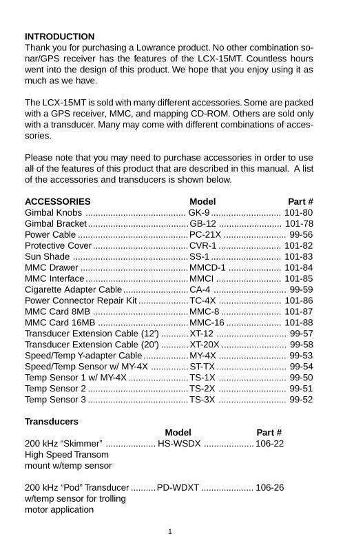
INTRODUCTIONThank you for purchasing a Lowrance product. No other combination so-nar/GPS receiver has the features of the LCX-15MT. Countless hourswent into the design of this product. We hope that you enjoy using it asmuch as we have.
The LCX-15MT is sold with many different accessories. Some are packedwith a GPS receiver, MMC, and mapping CD-ROM. Others are sold onlywith a transducer. Many may come with different combinations of acces-sories.
Please note that you may need to purchase accessories in order to useall of the features of this product that are described in this manual. A listof the accessories and transducers is shown below.
ACCESSORIES Model Part #Gimbal Knobs ........................................ GK-9 ............................ 101-80Gimbal Bracket ........................................GB-12 ......................... 101-78Power Cable ............................................PC-21X ......................... 99-56Protective Cover ......................................CVR-1 ......................... 101-82Sun Shade ..............................................SS-1 ............................ 101-83MMC Drawer ...........................................MMCD-1 ..................... 101-84MMC Interface .........................................MMCI .......................... 101-85Cigarette Adapter Cable ..........................CA-4 ............................. 99-59Power Connector Repair Kit ....................TC-4X ......................... 101-86MMC Card 8MB ......................................MMC-8 ........................ 101-87MMC Card 16MB ....................................MMC-16 ...................... 101-88Transducer Extension Cable (12') ...........XT-12 ............................ 99-57Transducer Extension Cable (20') ...........XT-20X .......................... 99-58Speed/Temp Y-adapter Cable ..................MY-4X ........................... 99-53Speed/Temp Sensor w/ MY-4X ...............ST-TX ............................ 99-54Temp Sensor 1 w/ MY-4X ........................TS-1X ........................... 99-50Temp Sensor 2 ........................................TS-2X ........................... 99-51Temp Sensor 3 ........................................TS-3X ........................... 99-52
TransducersModel Part #
200 kHz “Skimmer” .................... HS-WSDX .................... 106-22High Speed Transommount w/temp sensor
200 kHz “Pod” Transducer ..........PD-WDXT ..................... 106-26w/temp sensor for trollingmotor application
2
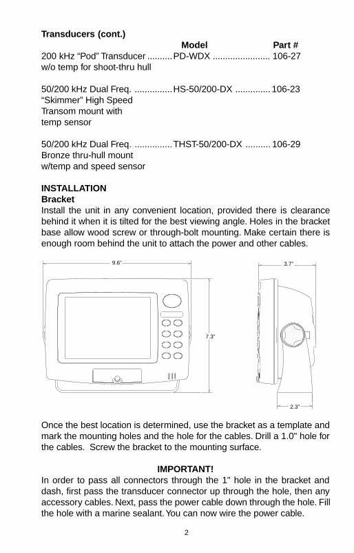
Transducers (cont.)Model Part #
200 kHz “Pod” Transducer ..........PD-WDX ....................... 106-27w/o temp for shoot-thru hull
50/200 kHz Dual Freq. ...............HS-50/200-DX .............. 106-23“Skimmer” High SpeedTransom mount withtemp sensor
50/200 kHz Dual Freq. ...............THST-50/200-DX .......... 106-29Bronze thru-hull mountw/temp and speed sensor
INSTALLATIONBracketInstall the unit in any convenient location, provided there is clearancebehind it when it is tilted for the best viewing angle. Holes in the bracketbase allow wood screw or through-bolt mounting. Make certain there isenough room behind the unit to attach the power and other cables.
Once the best location is determined, use the bracket as a template andmark the mounting holes and the hole for the cables. Drill a 1.0" hole forthe cables. Screw the bracket to the mounting surface.
IMPORTANT!In order to pass all connectors through the 1" hole in the bracket anddash, first pass the transducer connector up through the hole, then anyaccessory cables. Next, pass the power cable down through the hole. Fillthe hole with a marine sealant. You can now wire the power cable.
9.6”
7.3”
3.7”
2.3”
3
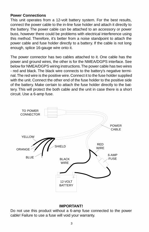
Power ConnectionsThis unit operates from a 12-volt battery system. For the best results,connect the power cable to the in-line fuse holder and attach it directly tothe battery. The power cable can be attached to an accessory or powerbuss, however there could be problems with electrical interference usingthis method. Therefore, it’s better from a noise standpoint to attach thepower cable and fuse holder directly to a battery. If the cable is not longenough, splice 16-gauge wire onto it.
The power connector has two cables attached to it. One cable has thepower and ground wires, the other is for the NMEA/DGPS interface. Seebelow for NMEA/DGPS wiring instructions. The power cable has two wires- red and black. The black wire connects to the battery’s negative termi-nal. The red wire is the positive wire. Connect it to the fuse holder suppliedwith the unit. Connect the other end of the fuse holder to the positive sideof the battery. Make certain to attach the fuse holder directly to the bat-tery. This will protect the both cable and the unit in case there is a shortcircuit. Use a 6-amp fuse.
IMPORTANT!Do not use this product without a 6-amp fuse connected to the powercable! Failure to use a fuse will void your warranty.
TO POWERCONNECTOR
12-VOLTBATTERY
6-AMPFUSE
POWERCABLE
BLACKWIRE
REDWIRE
YELLOW
ORANGE
BLUE
SHIELD
4
To prevent electrical interference, route the power, transducer, and GPScables away from other wiring, especially the engine’s wiring harness.VHF radio antenna cables radiate noise when transmitting, so be certainto keep the unit’s wires away from it, also.
NMEA/DGPSNMEA is a standard communications format for marine electronic equip-ment. For example, an autopilot can connect to the NMEA interface onthe LCX-15MT and receive positioning information.
DGPS is an acronym for Differential Global Positioning System. The mostpopular DGPS system relies on a grid of ground-based transmitters thatsend correction signals to DGPS receivers. These in turn, connect to theGPS receiver (such as the LCX-15MT with the LGC-12S GPS module).This gives more accurate positions than is otherwise possible.
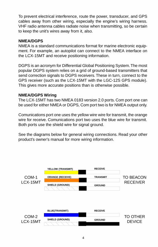
NMEA/DGPS WiringThe LCX-15MT has two NMEA 0183 version 2.0 ports. Com port one canbe used for either NMEA or DGPS, Com port two is for NMEA output only.
Comunications port one uses the yellow wire wire for transmit, the orangewire for receive. Comunications port two uses the blue wire for transmit.Both ports use the shield wire for signal ground.
See the diagrams below for general wiring connections. Read your otherproduct’s owner’s manual for more wiring information.
COM-1LCX-15MT
TO BEACONRECEIVER
YELLOW (TRANSMIT)
ORANGE (RECEIVE)
SHIELD (GROUND)
RECEIVE
TRANSMIT
GROUND
COM-2LCX-15MT
TO OTHERDEVICE
BLUE(TRANSMIT)
SHIELD (GROUND)
RECEIVE
GROUND
5
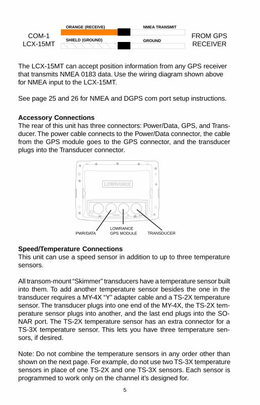
COM-1LCX-15MT
FROM GPSRECEIVER
ORANGE (RECEIVE)
SHIELD (GROUND)
NMEA TRANSMIT
GROUND
The LCX-15MT can accept position information from any GPS receiverthat transmits NMEA 0183 data. Use the wiring diagram shown abovefor NMEA input to the LCX-15MT.
See page 25 and 26 for NMEA and DGPS com port setup instructions.
Accessory ConnectionsThe rear of this unit has three connectors: Power/Data, GPS, and Trans-ducer. The power cable connects to the Power/Data connector, the cablefrom the GPS module goes to the GPS connector, and the transducerplugs into the Transducer connector.
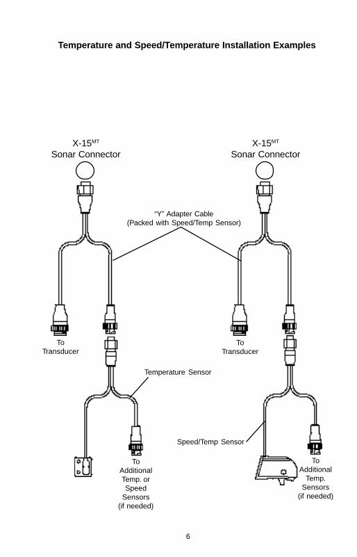
Speed/Temperature ConnectionsThis unit can use a speed sensor in addition to up to three temperaturesensors.
All transom-mount “Skimmer” transducers have a temperature sensor builtinto them. To add another temperature sensor besides the one in thetransducer requires a MY-4X “Y” adapter cable and a TS-2X temperaturesensor. The transducer plugs into one end of the MY-4X, the TS-2X tem-perature sensor plugs into another, and the last end plugs into the SO-NAR port. The TS-2X temperature sensor has an extra connector for aTS-3X temperature sensor. This lets you have three temperature sen-sors, if desired.
Note: Do not combine the temperature sensors in any order other thanshown on the next page. For example, do not use two TS-3X temperaturesensors in place of one TS-2X and one TS-3X sensors. Each sensor isprogrammed to work only on the channel it’s designed for.
PWR/DATALOWRANCEGPS MODULE TRANSDUCER
6
X-15MT
Sonar Connector
“Y” Adapter Cable(Packed with Speed/Temp Sensor)
Temperature Sensor
Speed/Temp Sensor
X-15MT
Sonar Connector
Temperature and Speed/Temperature Installation Examples
ToTransducer
ToTransducer
ToAdditionalTemp. orSpeed
Sensors(if needed)
ToAdditional
Temp.Sensors
(if needed)

7
MMCThis unit can use up to two MMC (MultiMediaCard) cartridges. They storethe maps, waypoint and route information, sonar data, and more.
To install a MMC cartridge, twist the drawer retainer counter-clockwiseand pull. The drawer will come out of the unit. Place the MMC cartridgeFACE DOWN. (see above) Slide the drawer back into the unit and twistthe retainer clockwise. The MMC is now ready for use.
For more information on saving and recalling sonar data to the MMC, seepage 68.
Map storage requires the MapCreate™ software and a MMC Interface. Ifyour unit did not come with these, they are available for purchase sepa-rately.
You can also store plot trails, icons, waypoints, and routes on a MMC. Seepage 69 for more information.
8
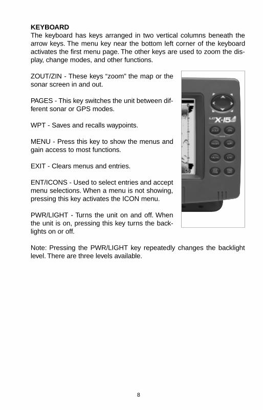
KEYBOARDThe keyboard has keys arranged in two vertical columns beneath thearrow keys. The menu key near the bottom left corner of the keyboardactivates the first menu page. The other keys are used to zoom the dis-play, change modes, and other functions.
ZOUT/ZIN - These keys “zoom” the map or thesonar screen in and out.
PAGES - This key switches the unit between dif-ferent sonar or GPS modes.
WPT - Saves and recalls waypoints.
MENU - Press this key to show the menus andgain access to most functions.
EXIT - Clears menus and entries.
ENT/ICONS - Used to select entries and acceptmenu selections. When a menu is not showing,pressing this key activates the ICON menu.
PWR/LIGHT - Turns the unit on and off. Whenthe unit is on, pressing this key turns the back-lights on or off.
Note: Pressing the PWR/LIGHT key repeatedly changes the backlightlevel. There are three levels available.
9
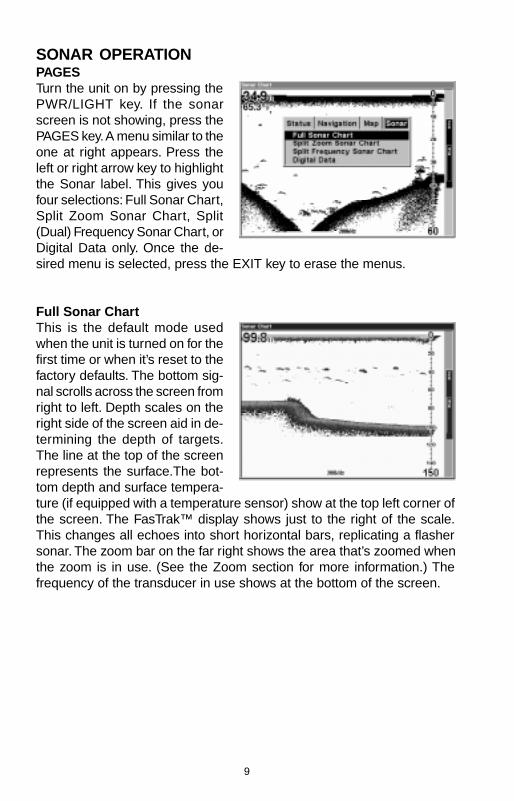
SONAR OPERATIONPAGESTurn the unit on by pressing thePWR/LIGHT key. If the sonarscreen is not showing, press thePAGES key. A menu similar to theone at right appears. Press theleft or right arrow key to highlightthe Sonar label. This gives youfour selections: Full Sonar Chart,Split Zoom Sonar Chart, Split(Dual) Frequency Sonar Chart, orDigital Data only. Once the de-sired menu is selected, press the EXIT key to erase the menus.
Full Sonar ChartThis is the default mode usedwhen the unit is turned on for thefirst time or when it’s reset to thefactory defaults. The bottom sig-nal scrolls across the screen fromright to left. Depth scales on theright side of the screen aid in de-termining the depth of targets.The line at the top of the screenrepresents the surface.The bot-tom depth and surface tempera-ture (if equipped with a temperature sensor) show at the top left corner ofthe screen. The FasTrak™ display shows just to the right of the scale.This changes all echoes into short horizontal bars, replicating a flashersonar. The zoom bar on the far right shows the area that’s zoomed whenthe zoom is in use. (See the Zoom section for more information.) Thefrequency of the transducer in use shows at the bottom of the screen.
10
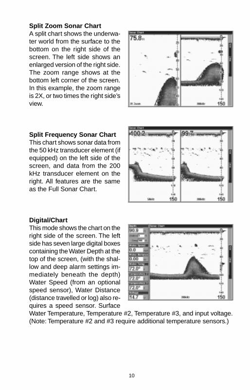
Split Zoom Sonar ChartA split chart shows the underwa-ter world from the surface to thebottom on the right side of thescreen. The left side shows anenlarged version of the right side.The zoom range shows at thebottom left corner of the screen.In this example, the zoom rangeis 2X, or two times the right side’sview.
Split Frequency Sonar ChartThis chart shows sonar data fromthe 50 kHz transducer element (ifequipped) on the left side of thescreen, and data from the 200kHz transducer element on theright. All features are the sameas the Full Sonar Chart.
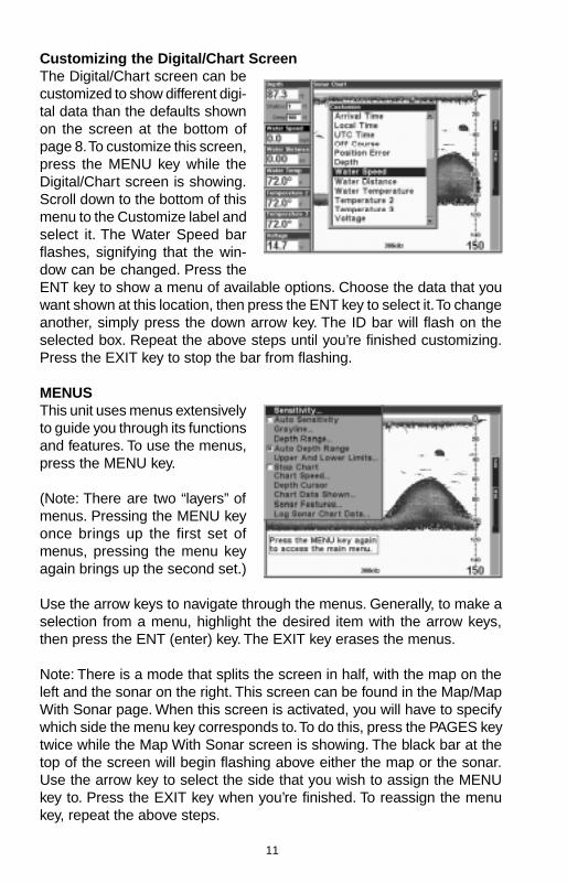
Digital/ChartThis mode shows the chart on theright side of the screen. The leftside has seven large digital boxescontaining the Water Depth at thetop of the screen, (with the shal-low and deep alarm settings im-mediately beneath the depth)Water Speed (from an optionalspeed sensor), Water Distance(distance travelled or log) also re-quires a speed sensor. SurfaceWater Temperature, Temperature #2, Temperature #3, and input voltage.(Note: Temperature #2 and #3 require additional temperature sensors.)
11
Customizing the Digital/Chart ScreenThe Digital/Chart screen can becustomized to show different digi-tal data than the defaults shownon the screen at the bottom ofpage 8. To customize this screen,press the MENU key while theDigital/Chart screen is showing.Scroll down to the bottom of thismenu to the Customize label andselect it. The Water Speed barflashes, signifying that the win-dow can be changed. Press theENT key to show a menu of available options. Choose the data that youwant shown at this location, then press the ENT key to select it. To changeanother, simply press the down arrow key. The ID bar will flash on theselected box. Repeat the above steps until you’re finished customizing.Press the EXIT key to stop the bar from flashing.
MENUSThis unit uses menus extensivelyto guide you through its functionsand features. To use the menus,press the MENU key.
(Note: There are two “layers” ofmenus. Pressing the MENU keyonce brings up the first set ofmenus, pressing the menu keyagain brings up the second set.)
Use the arrow keys to navigate through the menus. Generally, to make aselection from a menu, highlight the desired item with the arrow keys,then press the ENT (enter) key. The EXIT key erases the menus.
Note: There is a mode that splits the screen in half, with the map on theleft and the sonar on the right. This screen can be found in the Map/MapWith Sonar page. When this screen is activated, you will have to specifywhich side the menu key corresponds to. To do this, press the PAGES keytwice while the Map With Sonar screen is showing. The black bar at thetop of the screen will begin flashing above either the map or the sonar.Use the arrow key to select the side that you wish to assign the MENUkey to. Press the EXIT key when you’re finished. To reassign the menukey, repeat the above steps.
12
SONAR OPTIONSSensitivityThe sensitivity controls the ability of the unit to pick up echoes. A lowsensitivity level excludes much of the bottom information, fish signals,and other target information. High sensitivity levels let you see this detail,but it can also clutter the screen with many undesired signals. Typically,the best sensitivity level shows a good solid bottom signal with Graylineand some surface clutter.
The sensitivity is adjusted to keep a solid bottom signal displayed, plus alittle more when the unit is in the automatic mode. This gives it the capa-bility to show fish and other detail.
However, situations occur where it becomes necessary to increase ordecrease the sensitivity. This typically happens when you wish to seemore detail, so an increase in sensitivity is indicated. The procedure toadjust it is the same whether the unit is in the automatic or manual mode.
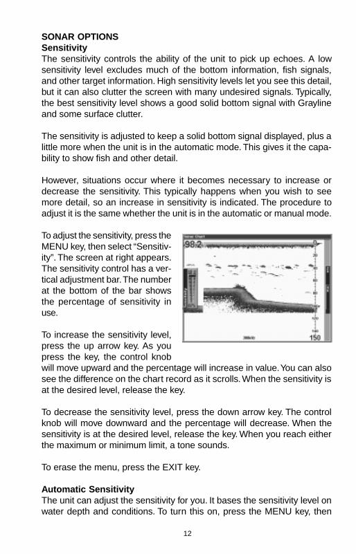
To adjust the sensitivity, press theMENU key, then select “Sensitiv-ity”. The screen at right appears.The sensitivity control has a ver-tical adjustment bar. The numberat the bottom of the bar showsthe percentage of sensitivity inuse.
To increase the sensitivity level,press the up arrow key. As youpress the key, the control knobwill move upward and the percentage will increase in value. You can alsosee the difference on the chart record as it scrolls. When the sensitivity isat the desired level, release the key.
To decrease the sensitivity level, press the down arrow key. The controlknob will move downward and the percentage will decrease. When thesensitivity is at the desired level, release the key. When you reach eitherthe maximum or minimum limit, a tone sounds.
To erase the menu, press the EXIT key.
Automatic SensitivityThe unit can adjust the sensitivity for you. It bases the sensitivity level onwater depth and conditions. To turn this on, press the MENU key, then
13
select “Auto Sensitivity” and press the ENT key. To turn it off, repeat theabove steps. Press the EXIT key to erase the menu.
GRAYLINE®
GRAYLINE lets you distinguish between strong and weak echoes. It “paints”gray on targets that are stronger than a preset value. This allows you totell the difference between a hard and soft bottom. For example, a soft,muddy or weedy bottom returns a weaker signal which is shown with anarrow or no gray line. A hard bottom returns a strong signal which causesa wide gray line.
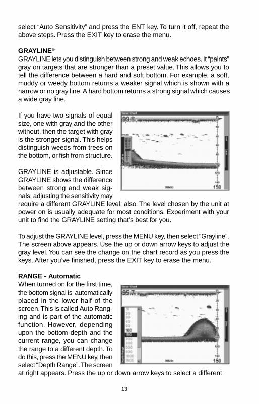
If you have two signals of equalsize, one with gray and the otherwithout, then the target with grayis the stronger signal. This helpsdistinguish weeds from trees onthe bottom, or fish from structure.
GRAYLINE is adjustable. SinceGRAYLINE shows the differencebetween strong and weak sig-nals, adjusting the sensitivity mayrequire a different GRAYLINE level, also. The level chosen by the unit atpower on is usually adequate for most conditions. Experiment with yourunit to find the GRAYLINE setting that’s best for you.
To adjust the GRAYLINE level, press the MENU key, then select “Grayline”.The screen above appears. Use the up or down arrow keys to adjust thegray level. You can see the change on the chart record as you press thekeys. After you’ve finished, press the EXIT key to erase the menu.
RANGE - AutomaticWhen turned on for the first time,the bottom signal is automaticallyplaced in the lower half of thescreen. This is called Auto Rang-ing and is part of the automaticfunction. However, dependingupon the bottom depth and thecurrent range, you can changethe range to a different depth. Todo this, press the MENU key, thenselect “Depth Range”. The screenat right appears. Press the up or down arrow keys to select a different
14
range that’s highlighted. The range numbers that are gray cannot be se-lected. When you’re finished, press the EXIT key to erase the menu.
RANGE - ManualYou have complete control over the range when the unit is in the manualmode.
To change the range, first turn the automatic depth range off by pressingthe MENU key, then selecting “Auto Depth Range”, then press the ENTkey to turn it off. Next, select “Depth Range”. Press the up or down arrowkeys to select a different range. The available ranges are 0-10, 20, 30, 40,60, 100, 150, 200, 300, 500, 800, 1000, 1500, 2000, and 3000 feet. Afterselecting the range, press the EXIT key to erase the range menu.
NOTE: The sonar’s depth capability depends on the transducer installa-tion, water and bottom conditions, and other factors.
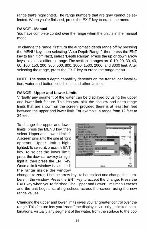
RANGE - Upper and Lower LimitsVirtually any segment of the water can be displayed by using the upperand lower limit feature. This lets you pick the shallow and deep rangelimits that are shown on the screen, provided there is at least ten feetbetween the upper and lower limit. For example, a range from 12 feet to34 feet.
To change the upper and lowerlimits, press the MENU key, thenselect “Upper and Lower Limits”.A screen similar to the one at rightappears. Upper Limit is high-lighted. To select it, press the ENTkey. To select the lower limit,press the down arrow key to high-light it, then press the ENT key.Once a limit window is selected,the range inside the windowchanges to zeros. Use the arrow keys to both select and change the num-bers in the window. Press the ENT key to accept the change. Press theEXIT key when you’re finished. The Upper and Lower Limit menu erasesand the unit begins scrolling echoes across the screen using the newrange values.
Changing the upper and lower limits gives you far greater control over therange. This feature lets you “zoom” the display in virtually unlimited com-binations. Virtually any segment of the water, from the surface to the bot-
15
tom can be shown, which enlarges targets to best suit your fishing needsand water conditions.
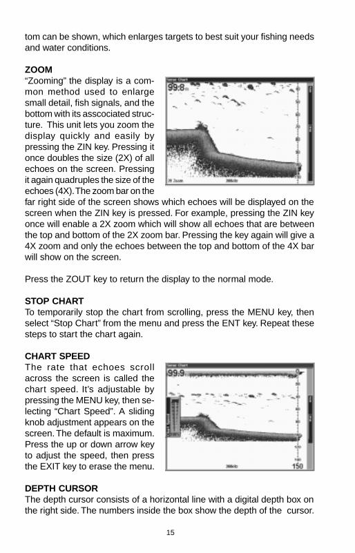
ZOOM“Zooming” the display is a com-mon method used to enlargesmall detail, fish signals, and thebottom with its asscociated struc-ture. This unit lets you zoom thedisplay quickly and easily bypressing the ZIN key. Pressing itonce doubles the size (2X) of allechoes on the screen. Pressingit again quadruples the size of theechoes (4X). The zoom bar on thefar right side of the screen shows which echoes will be displayed on thescreen when the ZIN key is pressed. For example, pressing the ZIN keyonce will enable a 2X zoom which will show all echoes that are betweenthe top and bottom of the 2X zoom bar. Pressing the key again will give a4X zoom and only the echoes between the top and bottom of the 4X barwill show on the screen.
Press the ZOUT key to return the display to the normal mode.
STOP CHARTTo temporarily stop the chart from scrolling, press the MENU key, thenselect “Stop Chart” from the menu and press the ENT key. Repeat thesesteps to start the chart again.
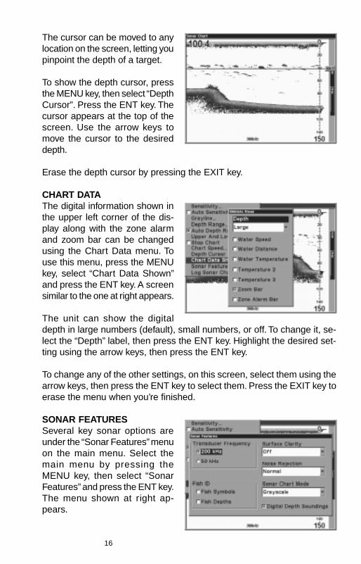
CHART SPEEDThe rate that echoes scrollacross the screen is called thechart speed. It’s adjustable bypressing the MENU key, then se-lecting “Chart Speed”. A slidingknob adjustment appears on thescreen. The default is maximum.Press the up or down arrow keyto adjust the speed, then pressthe EXIT key to erase the menu.
DEPTH CURSORThe depth cursor consists of a horizontal line with a digital depth box onthe right side. The numbers inside the box show the depth of the cursor.
16
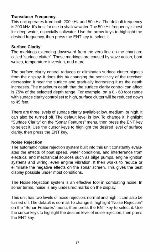
The cursor can be moved to anylocation on the screen, letting youpinpoint the depth of a target.
To show the depth cursor, pressthe MENU key, then select “DepthCursor”. Press the ENT key. Thecursor appears at the top of thescreen. Use the arrow keys tomove the cursor to the desireddepth.
Erase the depth cursor by pressing the EXIT key.
CHART DATAThe digital information shown inthe upper left corner of the dis-play along with the zone alarmand zoom bar can be changedusing the Chart Data menu. Touse this menu, press the MENUkey, select “Chart Data Shown”and press the ENT key. A screensimilar to the one at right appears.
The unit can show the digitaldepth in large numbers (default), small numbers, or off. To change it, se-lect the “Depth” label, then press the ENT key. Highlight the desired set-ting using the arrow keys, then press the ENT key.
To change any of the other settings, on this screen, select them using thearrow keys, then press the ENT key to select them. Press the EXIT key toerase the menu when you’re finished.
SONAR FEATURESSeveral key sonar options areunder the “Sonar Features” menuon the main menu. Select themain menu by pressing theMENU key, then select “SonarFeatures” and press the ENT key.The menu shown at right ap-pears.
17
Transducer FrequencyThis unit operates from both 200 kHz and 50 kHz. The default frequencyis 200 kHz. It’s best for use in shallow water. The 50 kHz frequency is bestfor deep water, especially saltwater. Use the arrow keys to highlight thedesired frequency, then press the ENT key to select it.
Surface ClarityThe markings extending downward from the zero line on the chart arecalled “surface clutter”. These markings are caused by wave action, boatwakes, temperature inversion, and more.
The surface clarity control reduces or eliminates surface clutter signalsfrom the display. It does this by changing the sensitivity of the receiver,decreasing it near the surface and gradually increasing it as the depthincreases. The maximum depth that the surface clarity control can affectis 75% of the selected depth range. For example, on a 0 - 60 foot rangewith surface clarity control set to high, surface clutter will be reduced downto 45 feet.
There are three levels of surface clarity available: low, medium, or high. Itcan also be turned off. The default level is low. To change it, highlight“Surface Clarity” on the “Sonar Features” menu, then press the ENT keyto select it. Use the cursor keys to highlight the desired level of surfaceclarity, then press the ENT key.
Noise RejectionThe automatic noise rejection system built into this unit constantly evalu-ates the effects of boat speed, water conditions, and interference fromelectrical and mechanical sources such as bilge pumps, engine ignitionsystems and wiring, even engine vibration. It then works to reduce oreliminate the negative effects on the sonar screen. This gives the bestdisplay possible under most conditions.
The Noise Rejection system is an effective tool in combating noise. Insonar terms, noise is any undesired marks on the display.
This unit has two levels of noise rejection: normal and high. It can also beturned off. The default is normal. To change it, highlight “Noise Rejection”on the “Sonar Features” menu, then press the ENT key to select it. Usethe cursor keys to highlight the desired level of noise rejection, then pressthe ENT key.
18
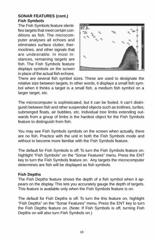
SONAR FEATURES (cont.)Fish SymbolsThe Fish Symbols feature identi-fies targets that meet certain con-ditions as fish. The microcom-puter analyses all echoes andeliminates surface clutter, ther-moclines, and other signals thatare undesirable. In most in-stances, remaining targets arefish. The Fish Symbols featuredisplays symbols on the screenin place of the actual fish echoes.There are several fish symbol sizes. These are used to designate therelative size between targets. In other words, it displays a small fish sym-bol when it thinks a target is a small fish, a medium fish symbol on alarger target, etc.
The microcomputer is sophisticated, but it can be fooled. It can’t distin-guish between fish and other suspended objects such as trotlines, turtles,submerged floats, air bubbles, etc. Individual tree limbs extending out-wards from a group of limbs is the hardest object for the Fish Symbolsfeature to distinguish from fish.
You may see Fish Symbols symbols on the screen when actually, thereare no fish. Practice with the unit in both the Fish Symbols mode andwithout to become more familiar with the Fish Symbols feature.
The default for Fish Symbols is off. To turn the Fish Symbols feature on,highlight “Fish Symbols” on the “Sonar Features” menu. Press the ENTkey to turn the Fish Symbols feature on. Any targets the microcomputerdetermines are fish will be displayed as fish symbols.
Fish DepthsThe Fish Depths feature shows the depth of a fish symbol when it ap-pears on the display. This lets you accurately gauge the depth of targets.This feature is available only when the Fish Symbols feature is on.
The default for Fish Depths is off. To turn the this feature on, highlight“Fish Depths” on the “Sonar Features” menu. Press the ENT key to turnthe Fish Depths feature on. (Note: If Fish Symbols is off, turning FishDepths on will also turn Fish Symbols on.)
19
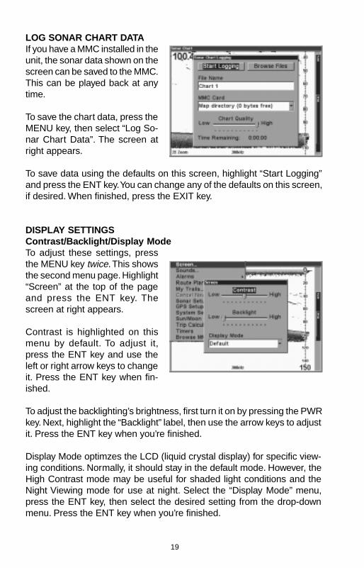
LOG SONAR CHART DATAIf you have a MMC installed in theunit, the sonar data shown on thescreen can be saved to the MMC.This can be played back at anytime.
To save the chart data, press theMENU key, then select “Log So-nar Chart Data”. The screen atright appears.
To save data using the defaults on this screen, highlight “Start Logging”and press the ENT key. You can change any of the defaults on this screen,if desired. When finished, press the EXIT key.
DISPLAY SETTINGSContrast/Backlight/Display ModeTo adjust these settings, pressthe MENU key twice. This showsthe second menu page. Highlight“Screen” at the top of the pageand press the ENT key. Thescreen at right appears.
Contrast is highlighted on thismenu by default. To adjust it,press the ENT key and use theleft or right arrow keys to changeit. Press the ENT key when fin-ished.
To adjust the backlighting’s brightness, first turn it on by pressing the PWRkey. Next, highlight the “Backlight” label, then use the arrow keys to adjustit. Press the ENT key when you’re finished.
Display Mode optimzes the LCD (liquid crystal display) for specific view-ing conditions. Normally, it should stay in the default mode. However, theHigh Contrast mode may be useful for shaded light conditions and theNight Viewing mode for use at night. Select the “Display Mode” menu,press the ENT key, then select the desired setting from the drop-downmenu. Press the ENT key when you’re finished.

20
AUDIOThe various sounds that the unitmakes can be customized to yourown taste. Press the MENU keytwice, then select “Sounds” fromthe main menu. The screen atright appears.
The volume control on the rightside of the menu adjusts the au-dio level for all sounds. To changeit, select “Volume”, press the ENTkey, then adjust it using the arrow keys. Press the ENT key when you’refinished.
The unit sounds a tone when a key is pressed. To turn this off, select “KeyPress Sounds” and press the ENT key. The same with “Alarm Sounds”.This silences the tone that’s sounded when an alarm is triggered.
“Alarm Style” lets you select the type of sound that’s played when analarm is triggered. Select “Alarm Style”, then press the ENT key. Choosethe desired setting, then press the ENT key again. The setting is savedand will be played the next time an alarm sounds.
ALARMSThis unit has three different types of sonar alarms. The first is the FishAlarm. It sounds when the Fish I.D. feature determines an echo or groupof echoes is a fish. Another alarm is the Zone Alarm which consists of abar. Any echo on the chart that appears inside this bar triggers this alarm.The last alarm is called the Depth Alarm. Only the bottom signal will trig-ger this alarm. This is useful as an anchor watch, a shallow water alert, orfor navigation.
To adjust an alarm, first press theMENU key twice, then select“Alarms”. Now select “SonarAlarms”. The screen shown atright appears. Follow the instruc-tions below for setting eachalarm.
21
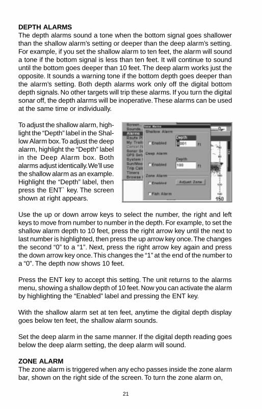
DEPTH ALARMSThe depth alarms sound a tone when the bottom signal goes shallowerthan the shallow alarm’s setting or deeper than the deep alarm’s setting.For example, if you set the shallow alarm to ten feet, the alarm will sounda tone if the bottom signal is less than ten feet. It will continue to sounduntil the bottom goes deeper than 10 feet. The deep alarm works just theopposite. It sounds a warning tone if the bottom depth goes deeper thanthe alarm’s setting. Both depth alarms work only off the digital bottomdepth signals. No other targets will trip these alarms. If you turn the digitalsonar off, the depth alarms will be inoperative. These alarms can be usedat the same time or individually.
To adjust the shallow alarm, high-light the “Depth” label in the Shal-low Alarm box. To adjust the deepalarm, highlight the “Depth” labelin the Deep Alarm box. Bothalarms adjust identically. We’ll usethe shallow alarm as an example.Highlight the “Depth” label, thenpress the ENT` key. The screenshown at right appears.
Use the up or down arrow keys to select the number, the right and leftkeys to move from number to number in the depth. For example, to set theshallow alarm depth to 10 feet, press the right arrow key until the next tolast number is highlighted, then press the up arrow key once. The changesthe second “0” to a “1”. Next, press the right arrow key again and pressthe down arrow key once. This changes the “1” at the end of the number toa “0”. The depth now shows 10 feet.
Press the ENT key to accept this setting. The unit returns to the alarmsmenu, showing a shallow depth of 10 feet. Now you can activate the alarmby highlighting the “Enabled” label and pressing the ENT key.
With the shallow alarm set at ten feet, anytime the digital depth displaygoes below ten feet, the shallow alarm sounds.
Set the deep alarm in the same manner. If the digital depth reading goesbelow the deep alarm setting, the deep alarm will sound.
ZONE ALARMThe zone alarm is triggered when any echo passes inside the zone alarmbar, shown on the right side of the screen. To turn the zone alarm on,
22
highlight the “Enabled” box in theZone Alarm box, then press theENT key. To adjust the zonealarm, highlight the “Adjust Zone”label, then press the ENT key. Ascreen similar to the one at rightappears.
The zone alarm bar shows on thescreen to the right of the zoombar. Any echo - fish, bottom,structure, etc will trigger the zone alarm.To adjust the top of the zone bar higher or lower, highlight “Upper Limit”and press the ENT key. To adjust the bottom of the bar, highlight “LowerLimit” and press the ENT key.
When the zone alarm is set, press the EXIT key to erase the menus.
FISH ALARMUse the fish alarm for a distinctive audible alarm when fish or other sus-pended objects are detected by the Fish I.D. feature. A different tone soundsfor each fish symbol size shown on the display. To turn the fish alarm on,select “Fish Alarm” from the sonar alarms menu and press the ENT key.Repeat the above steps to turn the fish alarm off.
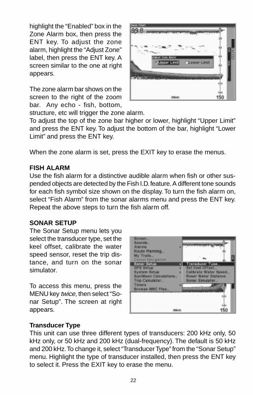
SONAR SETUPThe Sonar Setup menu lets youselect the transducer type, set thekeel offset, calibrate the waterspeed sensor, reset the trip dis-tance, and turn on the sonarsimulator.
To access this menu, press theMENU key twice, then select “So-nar Setup”. The screen at rightappears.
Transducer TypeThis unit can use three different types of transducers: 200 kHz only, 50kHz only, or 50 kHz and 200 kHz (dual-frequency). The default is 50 kHzand 200 kHz. To change it, select “Transducer Type” from the “Sonar Setup”menu. Highlight the type of transducer installed, then press the ENT keyto select it. Press the EXIT key to erase the menu.
23
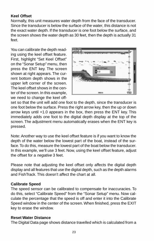
Keel OffsetNormally, this unit measures water depth from the face of the transducer.Since the transducer is below the surface of the water, this distance is notthe exact water depth. If the transducer is one foot below the surface, andthe screen shows the water depth as 30 feet, then the depth is actually 31feet.
You can calibrate the depth read-ing using the keel offset feature.First, highlight “Set Keel Offset”on the “Sonar Setup” menu, thenpress the ENT key. The screenshown at right appears. The cur-rent bottom depth shows in theupper left corner of the screen.The keel offset shows in the cen-ter of the screen. In this example,we need to change the keel off-set so that the unit will add one foot to the depth, since the transducer isone foot below the surface. Press the right arrow key, then the up or downarrow keys until +1.0 appears in the box, then press the ENT key. Thisimmediately adds one foot to the digital depth display at the top of thescreen. The adjustment menu automatically erases when the ENT key ispressed.
Note: Another way to use the keel offset feature is if you want to know thedepth of the water below the lowest part of the boat, instead of the sur-face. To do this, measure the lowest part of the boat below the transducer.In this example, we’ll use 3 feet. Now, using the keel offset feature, adjustthe offset for a negative 3 feet.
Please note that adjusting the keel offset only affects the digital depthdisplay and all features that use the digital depth, such as the depth alarmsand FishTrack. This doesn’t affect the chart at all.
Calibrate SpeedThe speed sensor can be calibrated to compensate for inaccuracies. Todo this, select “Calibrate Speed” from the “Sonar Setup” menu. Now cal-culate the percentage that the speed is off and enter it into the CalibrateSpeed window in the center of the screen. When finished, press the EXITkey to erase the window.
Reset Water DistanceThe Digital Data page shows distance travelled which is calculated from a
24
speed sensor input - not the GPS. This distance (called Water Distance)can be reset to zero using the “Reset Water Distance” label on the “SonarSetup” menu. Simply highlight “Reset Water Distance” and press the ENTkey. The menus automatically erase and the water distance display isreset to 0.00.
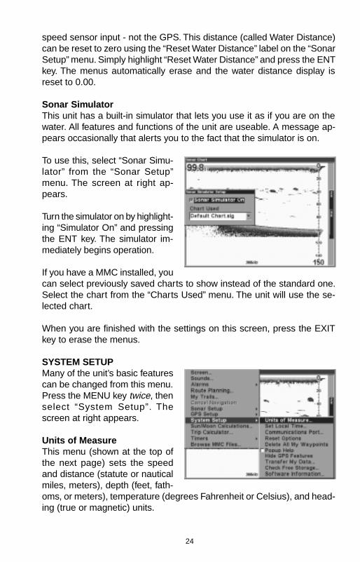
Sonar SimulatorThis unit has a built-in simulator that lets you use it as if you are on thewater. All features and functions of the unit are useable. A message ap-pears occasionally that alerts you to the fact that the simulator is on.
To use this, select “Sonar Simu-lator” from the “Sonar Setup”menu. The screen at right ap-pears.
Turn the simulator on by highlight-ing “Simulator On” and pressingthe ENT key. The simulator im-mediately begins operation.
If you have a MMC installed, youcan select previously saved charts to show instead of the standard one.Select the chart from the “Charts Used” menu. The unit will use the se-lected chart.
When you are finished with the settings on this screen, press the EXITkey to erase the menus.
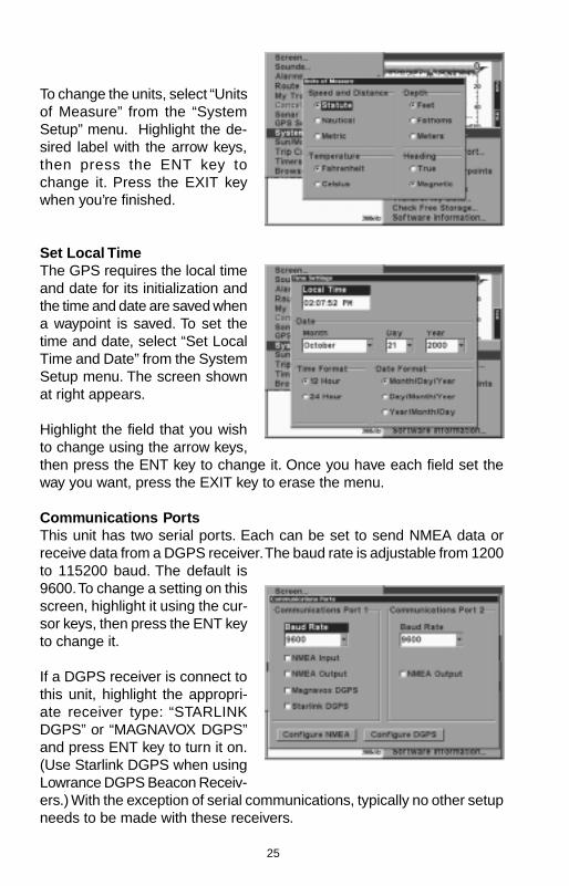
SYSTEM SETUPMany of the unit’s basic featurescan be changed from this menu.Press the MENU key twice, thenselect “System Setup”. Thescreen at right appears.
Units of MeasureThis menu (shown at the top ofthe next page) sets the speedand distance (statute or nauticalmiles, meters), depth (feet, fath-oms, or meters), temperature (degrees Fahrenheit or Celsius), and head-ing (true or magnetic) units.
25
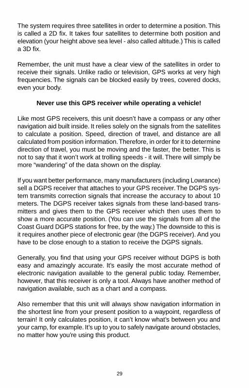
To change the units, select “Unitsof Measure” from the “SystemSetup” menu. Highlight the de-sired label with the arrow keys,then press the ENT key tochange it. Press the EXIT keywhen you’re finished.
Set Local TimeThe GPS requires the local timeand date for its initialization andthe time and date are saved whena waypoint is saved. To set thetime and date, select “Set LocalTime and Date” from the SystemSetup menu. The screen shownat right appears.
Highlight the field that you wishto change using the arrow keys,then press the ENT key to change it. Once you have each field set theway you want, press the EXIT key to erase the menu.
Communications PortsThis unit has two serial ports. Each can be set to send NMEA data orreceive data from a DGPS receiver. The baud rate is adjustable from 1200to 115200 baud. The default is9600. To change a setting on thisscreen, highlight it using the cur-sor keys, then press the ENT keyto change it.
If a DGPS receiver is connect tothis unit, highlight the appropri-ate receiver type: “STARLINKDGPS” or “MAGNAVOX DGPS”and press ENT key to turn it on.(Use Starlink DGPS when usingLowrance DGPS Beacon Receiv-ers.) With the exception of serial communications, typically no other setupneeds to be made with these receivers.

26
If you have any other Magnavox or Starlink compatible DGPS receiverconnected to this unit, (including a Lowrance DGPS receiver) you mayneed to change the settings. To do this, select “Configure DGPS”
Configure DGPSThis unit will recognize Starlink®and Magnavox® automaticDGPS receivers. If you have ei-ther one of these receivers, se-lect “Configure DGPS”. Thescreen at right appears. The sta-tus of the DGPS signal appearsin the boxes at the top, along withthe frequency and bit rate of theselected transmitter. To configurethe unit for DGPS, highlight the“Frequency” and press the ENT key. Use the arrow keys to enter the fre-quency of the station that you intend to use. Press the ENT key whenyou’re finished. Next, set the bit rate in the same manner. If you’re using aStarlink DGPS receiver, leave the “Starlink Auto Tuning Mode” checked. Ifnot, deselect this box.
Press the EXIT key when you’re finished with this menu.
Configure NMEAYou can configure the unit to usespecific NMEA sentences. Select“Configure NMEA” and press theENT key. The menu at right ap-pears showing the prefix of theavailable NMEA sentences. Acheck mark next to the prefixmeans that prefix is in use. Se-lect the prefix that you wish tochange by highlighting it, thenchange it by pressing the ENTkey. Press the EXIT key when you’re finished with this menu.
Reset OptionsTo reset all features to their factory defaults, select “Reset Options” fromthe “System Setup” menu. After selecting, a new menu appears, asking ifyou want to reset all options. Use the arrow keys to highlight the answer,and the ENT key to select it. The unit clears all menus and returns allsettings to the factory defaults.

27
Note: Reset Options does not erase any waypoints, routes, or plot trails.
Popup HelpHelp is available for virtually all of the menu labels on this unit. By high-lighting a menu item and leaving it highlighted for a few seconds, a “popup”message appears that describes the function of the the menu item.
This feature is on by default. To turn it off, highlight “Popup Help” from theSystem Setup menu, then press the ENT key. To turn it on again, repeatthe above steps.
Hide GPS featuresIf there is no GPS receiver attached to this unit, then the GPS menus andfeatures can be hidden from view by selecting “Hide GPS Features” onthe System Setup menu. The default is on. To turn them on again, select“Show GPS Features” from the System Setup menu.
Software InformationTo view the version number of the operating system, select “SoftwareInformation” from the System Setup menu. A screen appears with thesystem information. Press the EXIT key to erase this screen.
SUN/MOON CALCULATORThis unit has a sunrise/sunsetand moonrise/moonset calculatorthat shows this information any-where and anytime in the world.To use it, press the MENU keytwice, then select “Sun/MoonCalculator”. The screen shown atright appears. The calculations forboth are done at the same time.The sun and moon data fortoday’s date appear above theirrespective symbols. The moon symbol shows the approximate phase ofthe moon.
Today’s date shows at the top of the screen. If you want to know thesunrise/sunset for a different date, change it by selecting the month, day,or year by pressing the ENT key, then enter the new date with the arrowkeys. The unit recalculates the sun and moon data for the date you en-tered.
The sun and moon data show for your present position. To choose a dif

28
ferent location, select “Choose Position” and enter the new position. Theunit recalculates the sun and moon data for the location that you entered.
Press the EXIT key to erase this screen.
GPS OPERATION
NOTE: A LGC-12S GPS module or an external GPS receiver with NMEAoutput must be attached to this unit in order to use the position and navi-gation features.
WARNING!Use this product only as an aid to navigation. A careful navigator neverrelies on only one method to obtain position information.
CAUTIONThis GPS receiver (like all GPS navigation equipment) will show the short-est, most direct path to a waypoint. It provides navigation data to thewaypoint, regardless of obstructions. Therefore, the prudent navigator willnot only take advantage of all available navigation tools when travelling toa waypoint, but will also visually check to make certain a clear, safe pathto the waypoint is always available.
INTRODUCTION TO GPSThe Global Positioning System (GPS) was developed by the United StatesDepartment of Defense as a 24-hour a day, 365 days a year global navi-gation system for the military. Civilian availability was added (but with lessaccuracy) using the same satellites. Twenty-four satellites orbit the Earth.Three of these satellites are spares, unused until needed. The rest virtu-ally guarantee that at least four satellites are in view nearly anywhere onEarth at all times.
29
The system requires three satellites in order to determine a position. Thisis called a 2D fix. It takes four satellites to determine both position andelevation (your height above sea level - also called altitude.) This is calleda 3D fix.
Remember, the unit must have a clear view of the satellites in order toreceive their signals. Unlike radio or television, GPS works at very highfrequencies. The signals can be blocked easily by trees, covered docks,even your body.
Never use this GPS receiver while operating a vehicle!
Like most GPS receivers, this unit doesn’t have a compass or any othernavigation aid built inside. It relies solely on the signals from the satellitesto calculate a position. Speed, direction of travel, and distance are allcalculated from position information. Therefore, in order for it to determinedirection of travel, you must be moving and the faster, the better. This isnot to say that it won’t work at trolling speeds - it will. There will simply bemore “wandering” of the data shown on the display.
If you want better performance, many manufacturers (including Lowrance)sell a DGPS receiver that attaches to your GPS receiver. The DGPS sys-tem transmits correction signals that increase the accuracy to about 10meters. The DGPS receiver takes signals from these land-based trans-mitters and gives them to the GPS receiver which then uses them toshow a more accurate position. (You can use the signals from all of theCoast Guard DGPS stations for free, by the way.) The downside to this isit requires another piece of electronic gear (the DGPS receiver). And youhave to be close enough to a station to receive the DGPS signals.
Generally, you find that using your GPS receiver without DGPS is botheasy and amazingly accurate. It’s easily the most accurate method ofelectronic navigation available to the general public today. Remember,however, that this receiver is only a tool. Always have another method ofnavigation available, such as a chart and a compass.
Also remember that this unit will always show navigation information inthe shortest line from your present position to a waypoint, regardless ofterrain! It only calculates position, it can’t know what’s between you andyour camp, for example. It’s up to you to safely navigate around obstacles,no matter how you’re using this product.
30
FINDING YOUR POSITIONAuto SearchTo lock onto the satellites, the GPS receiver needs to know it’s currentposition, UTC time, and date. (Elevation (altitude) is also used in the equa-tion, but it’s rarely required to determine a position.) It needs this data sothat it can calculate which satellites should be in view. It then searches foronly those satellites. When your GPS receiver is turned on for the firsttime, it doesn’t know what your position or elevation (altitude) is. It doesknow the current UTC time and date since these were programmed into itat the factory and an internal clock keeps the time while the unit is turnedoff. (If the time and/or date are incorrect, you can set it using the “SetLocal Time” menu. See page 23 for more information.) It begins searchingfor the satellites using the above data that it acquired the last time it wasturned on. This probably was at the factory. Since it’s almost certain thatyou’re not at our factory, it’s probably looking for the wrong satellites. If itdoesn’t find the satellites it’s looking for after five minutes, it switches toAuto Search. The receiver looks for any satellite in the sky. Due to ad-vanced technology, the auto search time has shrunk to about five min-utes, so the longest time you should ever have to wait is ten minutes fromthe time you turn the unit on until it locks onto the satellites and shows aposition. Once the unit locks onto the satellites, it should take less than aminute to find your position the next time it’s turned on, provided youhaven’t moved more than approximately 100 miles from the last location itwas used.
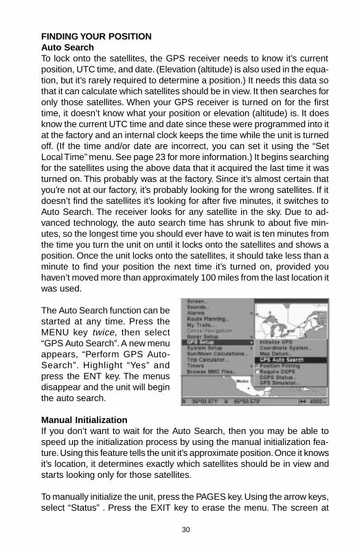
The Auto Search function can bestarted at any time. Press theMENU key twice, then select“GPS Auto Search”. A new menuappears, “Perform GPS Auto-Search”. Highlight “Yes” andpress the ENT key. The menusdisappear and the unit will beginthe auto search.
Manual InitializationIf you don’t want to wait for the Auto Search, then you may be able tospeed up the initialization process by using the manual initialization fea-ture. Using this feature tells the unit it’s approximate position. Once it knowsit’s location, it determines exactly which satellites should be in view andstarts looking only for those satellites.
To manually initialize the unit, press the PAGES key. Using the arrow keys,select “Status” . Press the EXIT key to erase the menu. The screen at

31
right appears. Now press theMENU key. Select “INITIALIZEGPS”. A screen similar to the onebelow right appears. Use the ar-row keys to move the crosshairsto your approximate location onthe map. You can use the ZIN andZOUT keys to enlarge the mapwhich makes it easier and fasterto find your location. The box atthe bottom of the screen showsthe latitude and longitude of thecursor position. A box pops up onthe screen, showing the name ofthe nearest highway (if a MMCwith a map is installed) along withthe distance and bearing from thelast known position. Once youhave the crosshairs on your lo-cation, press the ENT key. Theunit returns to the satellite statusscreen.
Using this manual initialization method loads a position that’s close toyours into the GPS receiver. It should now have position, time, and date,thereby giving it the data it needs to determine which satellites are inview. Once the satellites are known, the receiver searches for only thosesatellites, making a lock faster than an auto search method.
All position and navigation data flashes until the unit acquires a position.Do not rely on any data that is flashing! When the numbers are flashing,they represent the last known values when the unit lost it’s lock on thesatellites.
Position AquisitionWhen the receiver locks onto the satellites and calculates a position, itshows the message “Position Acquired” on the screen. Once the unit hasacquired the satellites and the position acquired message appears, it’sready for use.
(Note: The altitude data may still flash even if the unit shows a “PositionAcquired” message and all other data is not flashing. The unit must belocked onto at least four satellites to determine altitude. It only takes threesatellites to determine position. You can navigate with this unit if the alti
32
tude is flashing, simply ignore the altitude display until it quits flashing.)
REMEMBER, DO NOT NAVIGATE WITH THIS UNIT UNTIL THE NUM-BERS STOP FLASHING!
Require DGPSNormally, the unit will flash the position and navigation data when it losesthe satellite fix, but it does not flash the data when it loses the DGPS fix. Ifyou want the unit to flash the position and navigation data when it losesthe DGPS data, select the Status screen, highlight “Require DGPS” andpress the ENT key. Press the EXIT key to erase the menu.
GPS OPERATION
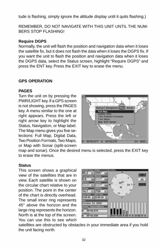
PAGESTurn the unit on by pressing thePWR/LIGHT key. If a GPS screenis not showing, press the PAGESkey. A menu similar to the one atright appears. Press the left orright arrow key to highlight theStatus, Navigation, or Map label.The Map menu gives you five se-lections: Full Map, Digital Data,Two Position Formats, Two Maps,or Map with Sonar (split-screenmap and sonar). Once the desired menu is selected, press the EXIT keyto erase the menus.
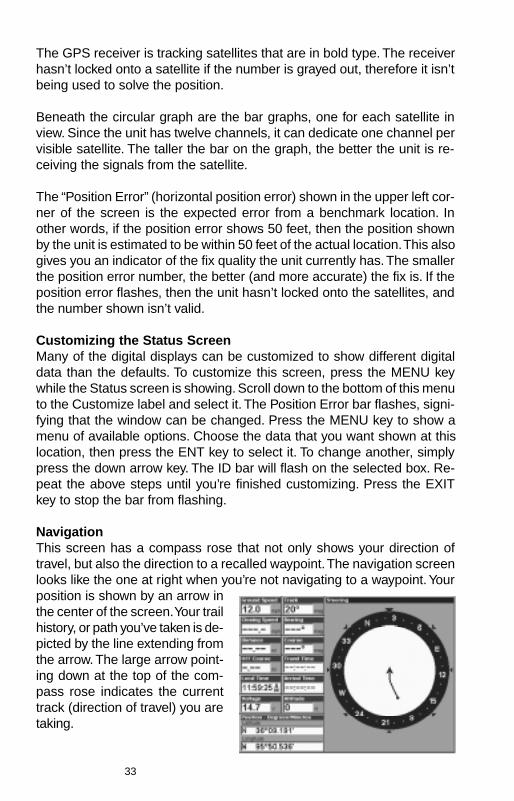
StatusThis screen shows a graphicalview of the satellites that are inview. Each satellite is shown onthe circular chart relative to yourposition. The point in the centerof the chart is directly overhead.The small inner ring represents45° above the horizon and thelarge ring represents the horizon.North is at the top of the screen.You can use this to see whichsatellites are obstructed by obstacles in your immediate area if you holdthe unit facing north.
33
The GPS receiver is tracking satellites that are in bold type. The receiverhasn’t locked onto a satellite if the number is grayed out, therefore it isn’tbeing used to solve the position.
Beneath the circular graph are the bar graphs, one for each satellite inview. Since the unit has twelve channels, it can dedicate one channel pervisible satellite. The taller the bar on the graph, the better the unit is re-ceiving the signals from the satellite.
The “Position Error” (horizontal position error) shown in the upper left cor-ner of the screen is the expected error from a benchmark location. Inother words, if the position error shows 50 feet, then the position shownby the unit is estimated to be within 50 feet of the actual location. This alsogives you an indicator of the fix quality the unit currently has. The smallerthe position error number, the better (and more accurate) the fix is. If theposition error flashes, then the unit hasn’t locked onto the satellites, andthe number shown isn’t valid.
Customizing the Status ScreenMany of the digital displays can be customized to show different digitaldata than the defaults. To customize this screen, press the MENU keywhile the Status screen is showing. Scroll down to the bottom of this menuto the Customize label and select it. The Position Error bar flashes, signi-fying that the window can be changed. Press the MENU key to show amenu of available options. Choose the data that you want shown at thislocation, then press the ENT key to select it. To change another, simplypress the down arrow key. The ID bar will flash on the selected box. Re-peat the above steps until you’re finished customizing. Press the EXITkey to stop the bar from flashing.
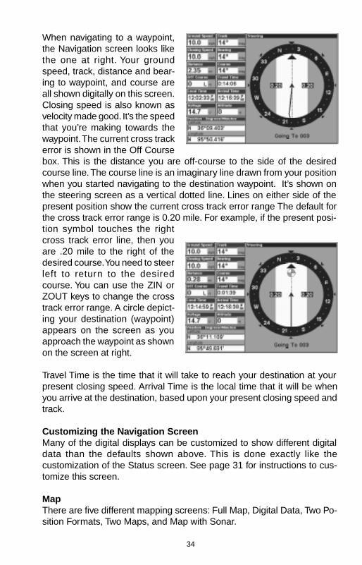
NavigationThis screen has a compass rose that not only shows your direction oftravel, but also the direction to a recalled waypoint. The navigation screenlooks like the one at right when you’re not navigating to a waypoint. Yourposition is shown by an arrow inthe center of the screen. Your trailhistory, or path you’ve taken is de-picted by the line extending fromthe arrow. The large arrow point-ing down at the top of the com-pass rose indicates the currenttrack (direction of travel) you aretaking.
34
When navigating to a waypoint,the Navigation screen looks likethe one at right. Your groundspeed, track, distance and bear-ing to waypoint, and course areall shown digitally on this screen.Closing speed is also known asvelocity made good. It’s the speedthat you’re making towards thewaypoint. The current cross trackerror is shown in the Off Coursebox. This is the distance you are off-course to the side of the desiredcourse line. The course line is an imaginary line drawn from your positionwhen you started navigating to the destination waypoint. It’s shown onthe steering screen as a vertical dotted line. Lines on either side of thepresent position show the current cross track error range The default forthe cross track error range is 0.20 mile. For example, if the present posi-tion symbol touches the rightcross track error line, then youare .20 mile to the right of thedesired course. You need to steerleft to return to the desiredcourse. You can use the ZIN orZOUT keys to change the crosstrack error range. A circle depict-ing your destination (waypoint)appears on the screen as youapproach the waypoint as shownon the screen at right.
Travel Time is the time that it will take to reach your destination at yourpresent closing speed. Arrival Time is the local time that it will be whenyou arrive at the destination, based upon your present closing speed andtrack.
Customizing the Navigation ScreenMany of the digital displays can be customized to show different digitaldata than the defaults shown above. This is done exactly like thecustomization of the Status screen. See page 31 for instructions to cus-tomize this screen.
MapThere are five different mapping screens: Full Map, Digital Data, Two Po-sition Formats, Two Maps, and Map with Sonar.
35
(Note: Maps must be downloaded from a MapCreate™ CD-ROM onto aMMC. The MMC must be installed into the unit before maps will show onthe screen. If your unit came with a MMC, MMC Interface, and CD-ROM,then follow the instructions in the separate booklet. If these items werenot included with your unit, then you will need to purchase the accessorypack that includes these items.)
The maps on the CD have the majority of their detail in far southernCanada, the continental United States and Hawaiian islands, northernMexico, the Bahamas, and Bermuda.
The map screens show your course and track from a “bird’s-eye” view. Ifyou’re navigating to a waypoint, the map shows your starting location,present position, course line, and destination. You don’t have to navigateto a waypoint, however, to use the map.
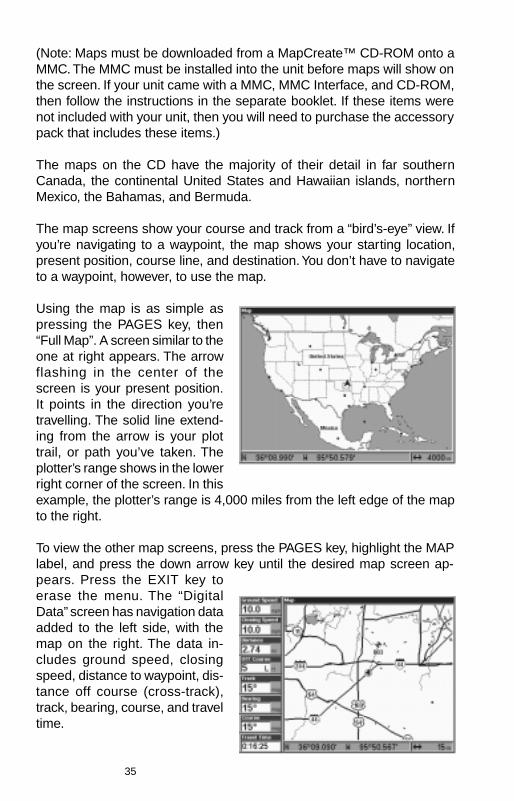
Using the map is as simple aspressing the PAGES key, then“Full Map”. A screen similar to theone at right appears. The arrowflashing in the center of thescreen is your present position.It points in the direction you’retravelling. The solid line extend-ing from the arrow is your plottrail, or path you’ve taken. Theplotter’s range shows in the lowerright corner of the screen. In thisexample, the plotter’s range is 4,000 miles from the left edge of the mapto the right.
To view the other map screens, press the PAGES key, highlight the MAPlabel, and press the down arrow key until the desired map screen ap-pears. Press the EXIT key toerase the menu. The “DigitalData” screen has navigation dataadded to the left side, with themap on the right. The data in-cludes ground speed, closingspeed, distance to waypoint, dis-tance off course (cross-track),track, bearing, course, and traveltime.
36
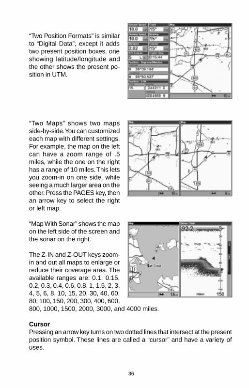
“Two Position Formats” is similarto “Digital Data”, except it addstwo present position boxes, oneshowing latitude/longitude andthe other shows the present po-sition in UTM.
“Two Maps” shows two mapsside-by-side. You can customizedeach map with different settings.For example, the map on the leftcan have a zoom range of .5miles, while the one on the righthas a range of 10 miles. This letsyou zoom-in on one side, whileseeing a much larger area on theother. Press the PAGES key, thenan arrow key to select the rightor left map.
“Map With Sonar” shows the mapon the left side of the screen andthe sonar on the right.
The Z-IN and Z-OUT keys zoom-in and out all maps to enlarge orreduce their coverage area. Theavailable ranges are: 0.1, 0.15,0.2, 0.3, 0.4, 0.6, 0.8, 1, 1.5, 2, 3,4, 5, 6, 8, 10, 15, 20, 30, 40, 60,80, 100, 150, 200, 300, 400, 600,800, 1000, 1500, 2000, 3000, and 4000 miles.
CursorPressing an arrow key turns on two dotted lines that intersect at the presentposition symbol. These lines are called a “cursor” and have a variety ofuses.

37
To turn the cursor on, simplypress the arrow key in the direc-tion you want the cursor to move.This lets you view areas on theplotter that are away from yourpresent position. The zoom-inand zoom-out keys work from thecursor’s position when it’s active- not the present position. You canzoom in on any detail, anywhere.The cursor can also place iconsand waypoints.
Cursor DistanceYou can use the cursor to find thedistance between two points.While the cursor is showing,press the MENU key, then select“FIND DISTANCE”. The unit re-turns to the mapping screen. Nowmove the cursor to the first loca-tion that you want to measure thedistance from and press the ENTkey. Next, move the cursor to theposition that you want to measurethe distance to. A line is drawn from the point when the ENT key waspressed to the cursor’s present location. The distance and bearing to thesecond location show in a box next to the cursor’s crosshairs. To mea-sure another two points, simply move the cursor and press the ENT key.
Press the EXIT key to erase the cursor. The unit centers your presentposition on the screen after erasing the cursor.
Map OrientationBy default, this receiver shows the map with north always at the top of thescreen. This is the way most maps and charts are printed on paper. Thisis fine if you’re always travelling due north. What you see to your left cor-responds to the left side of the map, to your right is shown on the rightside of the map, and so on. However, if you travel any other direction, themap doesn’t line up with your view of the world.
To correct this problem, a track-up mode rotates the map as you turn.Thus, what you see on the left side of the screen should always be to yourleft, and so on. A course-up mode keeps the map at the same orientation
38
as the initial bearing to the waypoint. A “N” shows to help you see whichdirection is north when either the track-up or course-up mode is on.
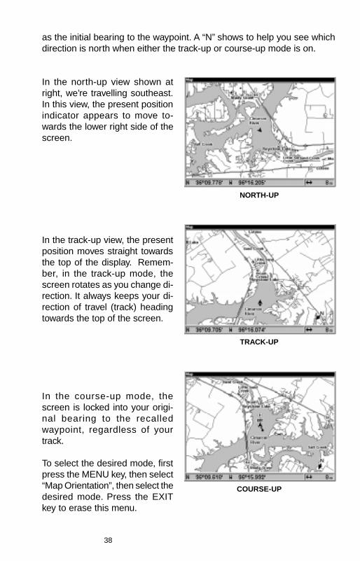
In the north-up view shown atright, we’re travelling southeast.In this view, the present positionindicator appears to move to-wards the lower right side of thescreen.
In the track-up view, the presentposition moves straight towardsthe top of the display. Remem-ber, in the track-up mode, thescreen rotates as you change di-rection. It always keeps your di-rection of travel (track) headingtowards the top of the screen.
NORTH-UP
TRACK-UP
COURSE-UP
In the course-up mode, thescreen is locked into your origi-nal bearing to the recalledwaypoint, regardless of yourtrack.
To select the desired mode, firstpress the MENU key, then select“Map Orientation”, then select thedesired mode. Press the EXITkey to erase this menu.
39
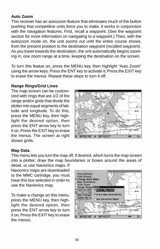
Auto ZoomThis receiver has an autozoom feature that eliminates much of the buttonpushing that competitive units force you to make. It works in conjunctionwith the navigation features. First, recall a waypoint. (See the waypointsection for more information on navigating to a waypoint.) Then, with theautozoom mode on, the unit zooms out until the entire course shows,from the present position to the destination waypoint (recalled waypoint).As you travel towards the destination, the unit automatically begins zoom-ing in, one zoom range at a time, keeping the destination on the screen.
To turn this featue on, press the MENU key, then highlight “Auto Zoom”using the arrow keys. Press the ENT key to activate it. Press the EXIT keyto erase the menus. Repeat these steps to turn it off.
Range Rings/Grid LinesThe map screen can be custom-ized with rings that are 1/2 of therange and/or grids that divide theplotter into equal segments of lati-tude and longitude. To do this,press the MENU key, then high-light the desired option, thenpress the ENT arrow key to turnit on. Press the EXIT key to erasethe menus. The screen at rightshows grids.
Map DataThis menu lets you turn the map off, if desired, which turns the map screeninto a plotter; draw the map boundaries or boxes around the areas ofdetail, or use Navionics maps. IfNavionics maps are downloadedto the MMC cartridge, you musthave this box selected in order touse the Navionics map.
To make a change on this menu,press the MENU key, then high-light the desired option, thenpress the ENT arrow key to turnit on. Press the EXIT key to erasethe menus.
40
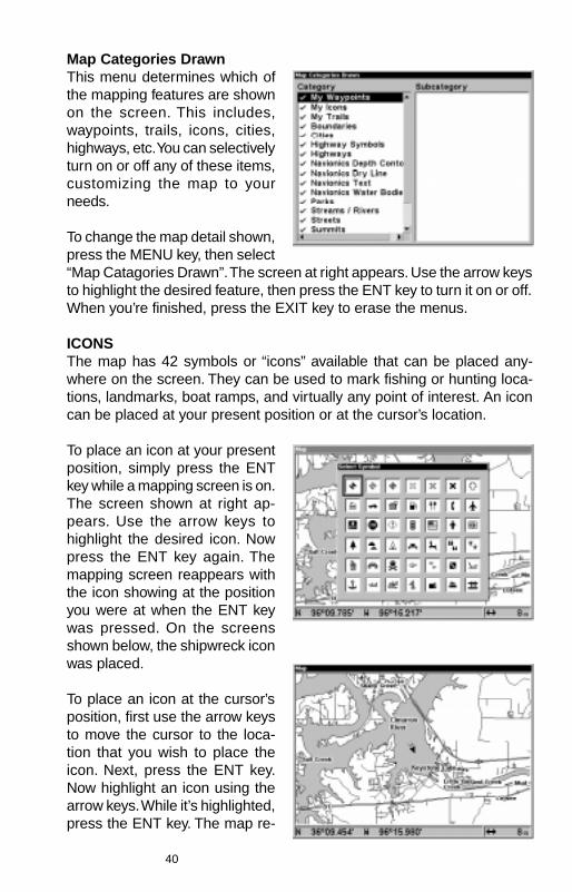
Map Categories DrawnThis menu determines which ofthe mapping features are shownon the screen. This includes,waypoints, trails, icons, cities,highways, etc. You can selectivelyturn on or off any of these items,customizing the map to yourneeds.
To change the map detail shown,press the MENU key, then select“Map Catagories Drawn”. The screen at right appears. Use the arrow keysto highlight the desired feature, then press the ENT key to turn it on or off.When you’re finished, press the EXIT key to erase the menus.
ICONSThe map has 42 symbols or “icons” available that can be placed any-where on the screen. They can be used to mark fishing or hunting loca-tions, landmarks, boat ramps, and virtually any point of interest. An iconcan be placed at your present position or at the cursor’s location.
To place an icon at your presentposition, simply press the ENTkey while a mapping screen is on.The screen shown at right ap-pears. Use the arrow keys tohighlight the desired icon. Nowpress the ENT key again. Themapping screen reappears withthe icon showing at the positionyou were at when the ENT keywas pressed. On the screensshown below, the shipwreck iconwas placed.
To place an icon at the cursor’sposition, first use the arrow keysto move the cursor to the loca-tion that you wish to place theicon. Next, press the ENT key.Now highlight an icon using thearrow keys. While it’s highlighted,press the ENT key. The map re-
41
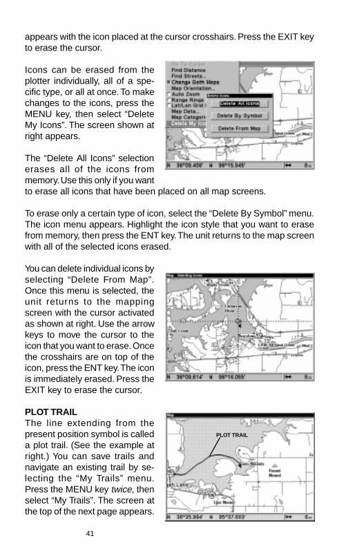
appears with the icon placed at the cursor crosshairs. Press the EXIT keyto erase the cursor.
Icons can be erased from theplotter individually, all of a spe-cific type, or all at once. To makechanges to the icons, press theMENU key, then select “DeleteMy Icons”. The screen shown atright appears.
The “Delete All Icons” selectionerases all of the icons frommemory. Use this only if you wantto erase all icons that have been placed on all map screens.
To erase only a certain type of icon, select the “Delete By Symbol” menu.The icon menu appears. Highlight the icon style that you want to erasefrom memory, then press the ENT key. The unit returns to the map screenwith all of the selected icons erased.
You can delete individual icons byselecting “Delete From Map”.Once this menu is selected, theunit returns to the mappingscreen with the cursor activatedas shown at right. Use the arrowkeys to move the cursor to theicon that you want to erase. Oncethe crosshairs are on top of theicon, press the ENT key. The iconis immediately erased. Press theEXIT key to erase the cursor.
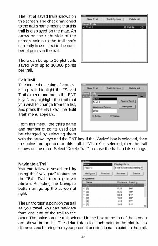
PLOT TRAILThe line extending from thepresent position symbol is calleda plot trail. (See the example atright.) You can save trails andnavigate an existing trail by se-lecting the “My Trails” menu.Press the MENU key twice, thenselect “My Trails”. The screen atthe top of the next page appears.
PLOT TRAIL
42
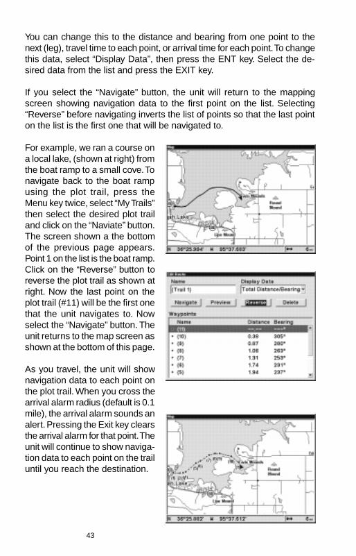
The list of saved trails shows onthis screen. The check mark nextto the trail’s name means that thistrail is displayed on the map. Anarrow on the right side of thescreen points to the trail that’scurrently in use, next to the num-ber of points in the trail.
There can be up to 10 plot trailssaved with up to 10,000 pointsper trail.
Edit TrailTo change the settings for an ex-isting trail, highlight the “SavedTrails” menu and press the ENTkey. Next, highlight the trail thatyou wish to change from the list,and press the ENT key. The “EditTrail” menu appears.
From this menu, the trail’s nameand number of points used canbe changed by selecting themwith the arrow keys and the ENT key. If the “Active” box is selected, thenthe points are updated on this trail. If “Visible” is selected, then the trailshows on the map. Select “Delete Trail” to erase the trail and its settings.
Navigate a TrailYou can follow a saved trail byusing the “Navigate” feature onthe “Edit Trail” menu (shownabove). Selecting the Navigatebutton brings up the screen atright.
The unit “drops” a point on the trailas you travel. You can navigatefrom one end of the trail to theother. The points on the trail selected in the box at the top of the screenare shown in the list. The default data for each point in the plot trail isdistance and bearing from your present position to each point on the trail.
43
You can change this to the distance and bearing from one point to thenext (leg), travel time to each point, or arrival time for each point. To changethis data, select “Display Data”, then press the ENT key. Select the de-sired data from the list and press the EXIT key.
If you select the “Navigate” button, the unit will return to the mappingscreen showing navigation data to the first point on the list. Selecting“Reverse” before navigating inverts the list of points so that the last pointon the list is the first one that will be navigated to.
For example, we ran a course ona local lake, (shown at right) fromthe boat ramp to a small cove. Tonavigate back to the boat rampusing the plot trail, press theMenu key twice, select “My Trails”then select the desired plot trailand click on the “Naviate” button.The screen shown a the bottomof the previous page appears.Point 1 on the list is the boat ramp.Click on the “Reverse” button toreverse the plot trail as shown atright. Now the last point on theplot trail (#11) will be the first onethat the unit navigates to. Nowselect the “Navigate” button. Theunit returns to the map screen asshown at the bottom of this page.
As you travel, the unit will shownavigation data to each point onthe plot trail. When you cross thearrival alarm radius (default is 0.1mile), the arrival alarm sounds analert. Pressing the Exit key clearsthe arrival alarm for that point. Theunit will continue to show naviga-tion data to each point on the trailuntil you reach the destination.
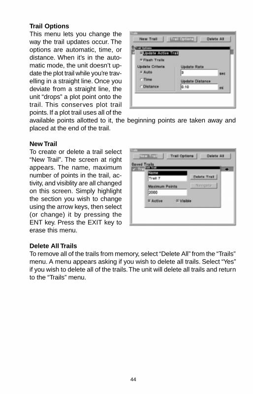
44
Trail OptionsThis menu lets you change theway the trail updates occur. Theoptions are automatic, time, ordistance. When it’s in the auto-matic mode, the unit doesn’t up-date the plot trail while you’re trav-elling in a straight line. Once youdeviate from a straight line, theunit “drops” a plot point onto thetrail. This conserves plot trailpoints. If a plot trail uses all of theavailable points allotted to it, the beginning points are taken away andplaced at the end of the trail.
New TrailTo create or delete a trail select“New Trail”. The screen at rightappears. The name, maximumnumber of points in the trail, ac-tivity, and visiblity are all changedon this screen. Simply highlightthe section you wish to changeusing the arrow keys, then select(or change) it by pressing theENT key. Press the EXIT key toerase this menu.
Delete All TrailsTo remove all of the trails from memory, select “Delete All” from the “Trails”menu. A menu appears asking if you wish to delete all trails. Select “Yes”if you wish to delete all of the trails. The unit will delete all trails and returnto the “Trails” menu.
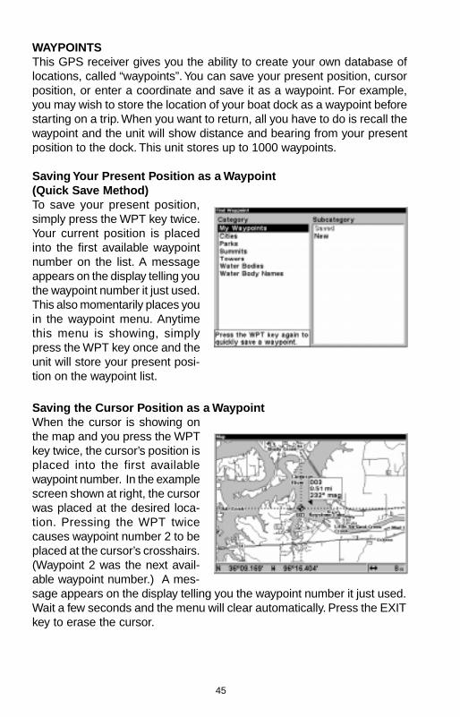
45
WAYPOINTSThis GPS receiver gives you the ability to create your own database oflocations, called “waypoints”. You can save your present position, cursorposition, or enter a coordinate and save it as a waypoint. For example,you may wish to store the location of your boat dock as a waypoint beforestarting on a trip. When you want to return, all you have to do is recall thewaypoint and the unit will show distance and bearing from your presentposition to the dock. This unit stores up to 1000 waypoints.
Saving Your Present Position as a Waypoint(Quick Save Method)To save your present position,simply press the WPT key twice.Your current position is placedinto the first available waypointnumber on the list. A messageappears on the display telling youthe waypoint number it just used.This also momentarily places youin the waypoint menu. Anytimethis menu is showing, simplypress the WPT key once and theunit will store your present posi-tion on the waypoint list.
Saving the Cursor Position as a WaypointWhen the cursor is showing onthe map and you press the WPTkey twice, the cursor’s position isplaced into the first availablewaypoint number. In the examplescreen shown at right, the cursorwas placed at the desired loca-tion. Pressing the WPT twicecauses waypoint number 2 to beplaced at the cursor’s crosshairs.(Waypoint 2 was the next avail-able waypoint number.) A mes-sage appears on the display telling you the waypoint number it just used.Wait a few seconds and the menu will clear automatically. Press the EXITkey to erase the cursor.
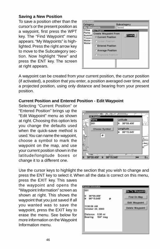
46
Saving a New PositionTo save a position other than thecursor’s or the present position asa waypoint, first press the WPTkey. The “Find Waypoint” menuappears. “My Waypoints” is high-lighted. Press the right arrow keyto move to the Subcategory sec-tion. Now highlight “New” andpress the ENT key. The screenat right appears.
A waypoint can be created from your current position, the cursor position(if activated), a position that you enter, a position averaged over time, anda projected position, using only distance and bearing from your presentposition.
Current Position and Entered Position - Edit WaypointSelecting “Current Position” or“Entered Position” brings up the“Edit Waypoint” menu as shownat right. Choosing this option letsyou change the defaults usedwhen the quick-save method isused. You can name the waypoint,choose a symbol to mark thewaypoint on the map, and useyour current position shown in thelatitude/longitude boxes orchange it to a different one.
Use the cursor keys to highlight the section that you wish to change andpress the ENT key to select it. When all the data is correct on this menu,press the EXIT key. This savesthe waypoint and opens the“Waypoint Information” screen asshown at right. This shows thewaypoint that you just saved If allyou wanted was to save thewaypoint, press the EXIT key toerase the menu. See below formore information on the WaypointInformation menu.

47
Average PositionThis feature averages your posi-tion. This helps to eliminate errorsin the position due to atmosphericeffects and other conditions.When the “Average Position”menu item is selected, a screensimilar to the one at right appears.The small plotter screen showsyour present position. The num-ber of positions used to calculatethe average position shows onthe right side of the screen, be-neath your present position. When you are ready to save the position,press the ENT key. This brings up the “Edit Waypoint” menu, as shown atthe bottom of the page 42. You can name the waypoint, choose a symbolto mark the waypoint on the map, and use your current position shown inthe latitude/longitude boxes or change it to a different one.
Use the cursor keys to highlight the section that you wish to change andpress the ENT key to select it. When all the data is correct on this menu,press the EXIT key. This saves the waypoint and opens the “WaypointInformation” screen as shown at the top of this page. This shows thewaypoint that you just saved. If all you wanted was to save the waypoint,press the EXIT key to erase the menu. See the next page for more infor-mation on the Waypoint Information menu.
Waypoint InformationThis screen shows the currentlyselected waypoint and it’s name,latitude/longitude, the local timeand date that it was saved, andthe distance and bearing fromyour present position to thewaypoint.
To navigate to a waypoint, select“Go To Waypoint”. The unit will in-stantly show navigation data tothe selected waypoint.
“Find On Map” returns the unit to a map display with the selected waypointand the cursor centered on the map. Pressing the EXIT key returns theunit to the Waypoint Information menu.
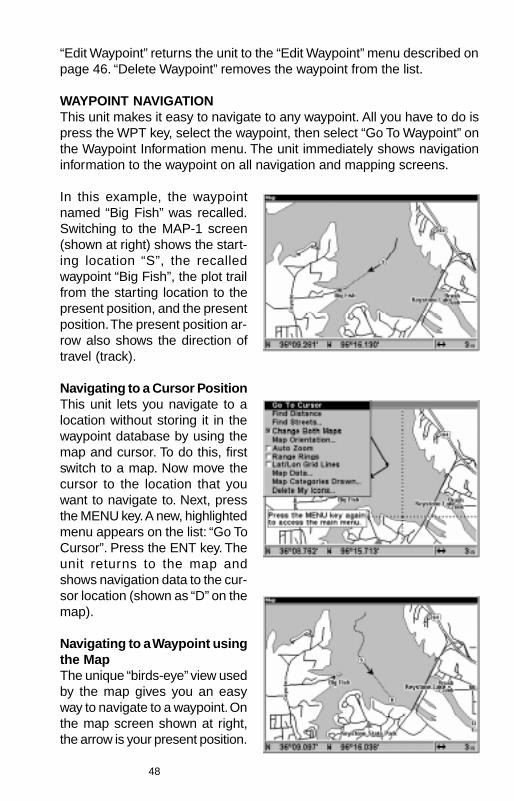
48
“Edit Waypoint” returns the unit to the “Edit Waypoint” menu described onpage 46. “Delete Waypoint” removes the waypoint from the list.
WAYPOINT NAVIGATIONThis unit makes it easy to navigate to any waypoint. All you have to do ispress the WPT key, select the waypoint, then select “Go To Waypoint” onthe Waypoint Information menu. The unit immediately shows navigationinformation to the waypoint on all navigation and mapping screens.
In this example, the waypointnamed “Big Fish” was recalled.Switching to the MAP-1 screen(shown at right) shows the start-ing location “S”, the recalledwaypoint “Big Fish”, the plot trailfrom the starting location to thepresent position, and the presentposition. The present position ar-row also shows the direction oftravel (track).
Navigating to a Cursor PositionThis unit lets you navigate to alocation without storing it in thewaypoint database by using themap and cursor. To do this, firstswitch to a map. Now move thecursor to the location that youwant to navigate to. Next, pressthe MENU key. A new, highlightedmenu appears on the list: “Go ToCursor”. Press the ENT key. Theunit returns to the map andshows navigation data to the cur-sor location (shown as “D” on themap).
Navigating to a Waypoint usingthe MapThe unique “birds-eye” view usedby the map gives you an easyway to navigate to a waypoint. Onthe map screen shown at right,the arrow is your present position.
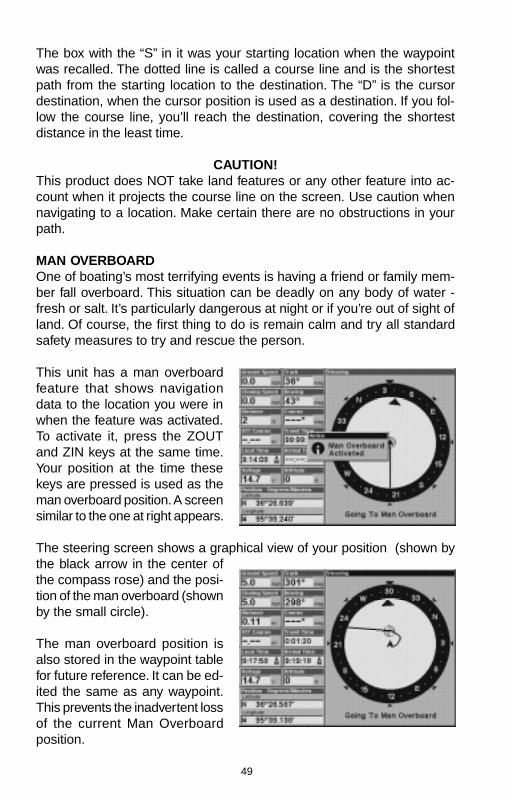
49
The box with the “S” in it was your starting location when the waypointwas recalled. The dotted line is called a course line and is the shortestpath from the starting location to the destination. The “D” is the cursordestination, when the cursor position is used as a destination. If you fol-low the course line, you’ll reach the destination, covering the shortestdistance in the least time.
CAUTION!This product does NOT take land features or any other feature into ac-count when it projects the course line on the screen. Use caution whennavigating to a location. Make certain there are no obstructions in yourpath.
MAN OVERBOARDOne of boating’s most terrifying events is having a friend or family mem-ber fall overboard. This situation can be deadly on any body of water -fresh or salt. It’s particularly dangerous at night or if you’re out of sight ofland. Of course, the first thing to do is remain calm and try all standardsafety measures to try and rescue the person.
This unit has a man overboardfeature that shows navigationdata to the location you were inwhen the feature was activated.To activate it, press the ZOUTand ZIN keys at the same time.Your position at the time thesekeys are pressed is used as theman overboard position. A screensimilar to the one at right appears.
The steering screen shows a graphical view of your position (shown bythe black arrow in the center ofthe compass rose) and the posi-tion of the man overboard (shownby the small circle).
The man overboard position isalso stored in the waypoint tablefor future reference. It can be ed-ited the same as any waypoint.This prevents the inadvertent lossof the current Man Overboardposition.
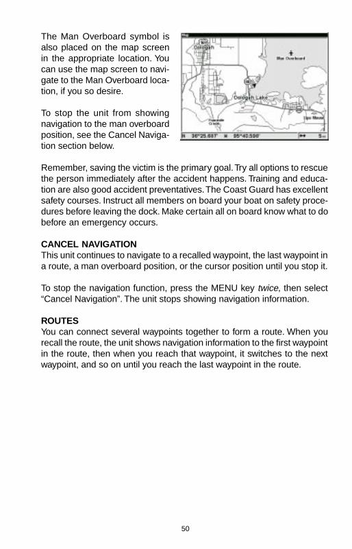
50
The Man Overboard symbol isalso placed on the map screenin the appropriate location. Youcan use the map screen to navi-gate to the Man Overboard loca-tion, if you so desire.
To stop the unit from showingnavigation to the man overboardposition, see the Cancel Naviga-tion section below.
Remember, saving the victim is the primary goal. Try all options to rescuethe person immediately after the accident happens. Training and educa-tion are also good accident preventatives. The Coast Guard has excellentsafety courses. Instruct all members on board your boat on safety proce-dures before leaving the dock. Make certain all on board know what to dobefore an emergency occurs.
CANCEL NAVIGATIONThis unit continues to navigate to a recalled waypoint, the last waypoint ina route, a man overboard position, or the cursor position until you stop it.
To stop the navigation function, press the MENU key twice, then select“Cancel Navigation”. The unit stops showing navigation information.
ROUTESYou can connect several waypoints together to form a route. When yourecall the route, the unit shows navigation information to the first waypointin the route, then when you reach that waypoint, it switches to the nextwaypoint, and so on until you reach the last waypoint in the route.
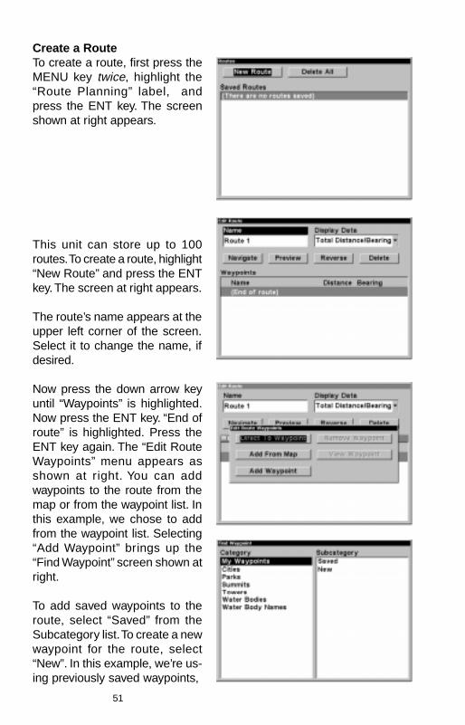
51
Create a RouteTo create a route, first press theMENU key twice, highlight the“Route Planning” label, andpress the ENT key. The screenshown at right appears.
This unit can store up to 100routes. To create a route, highlight“New Route” and press the ENTkey. The screen at right appears.
The route’s name appears at theupper left corner of the screen.Select it to change the name, ifdesired.
Now press the down arrow keyuntil “Waypoints” is highlighted.Now press the ENT key. “End ofroute” is highlighted. Press theENT key again. The “Edit RouteWaypoints” menu appears asshown at right. You can addwaypoints to the route from themap or from the waypoint list. Inthis example, we chose to addfrom the waypoint list. Selecting“Add Waypoint” brings up the“Find Waypoint” screen shown atright.
To add saved waypoints to theroute, select “Saved” from theSubcategory list. To create a newwaypoint for the route, select“New”. In this example, we’re us-ing previously saved waypoints,
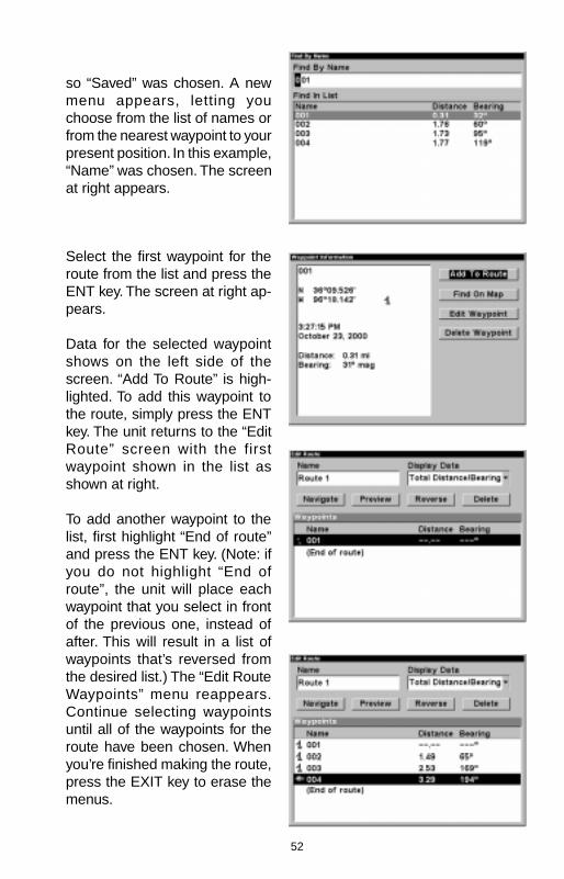
52
so “Saved” was chosen. A newmenu appears, letting youchoose from the list of names orfrom the nearest waypoint to yourpresent position. In this example,“Name” was chosen. The screenat right appears.
Select the first waypoint for theroute from the list and press theENT key. The screen at right ap-pears.
Data for the selected waypointshows on the left side of thescreen. “Add To Route” is high-lighted. To add this waypoint tothe route, simply press the ENTkey. The unit returns to the “EditRoute” screen with the firstwaypoint shown in the list asshown at right.
To add another waypoint to thelist, first highlight “End of route”and press the ENT key. (Note: ifyou do not highlight “End ofroute”, the unit will place eachwaypoint that you select in frontof the previous one, instead ofafter. This will result in a list ofwaypoints that’s reversed fromthe desired list.) The “Edit RouteWaypoints” menu reappears.Continue selecting waypointsuntil all of the waypoints for theroute have been chosen. Whenyou’re finished making the route,press the EXIT key to erase themenus.
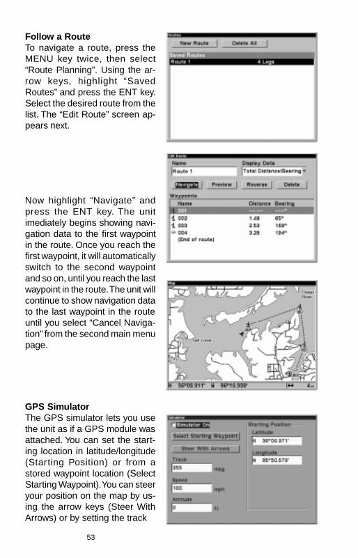
53
Follow a RouteTo navigate a route, press theMENU key twice, then select“Route Planning”. Using the ar-row keys, highlight “SavedRoutes” and press the ENT key.Select the desired route from thelist. The “Edit Route” screen ap-pears next.
Now highlight “Navigate” andpress the ENT key. The unitimediately begins showing navi-gation data to the first waypointin the route. Once you reach thefirst waypoint, it will automaticallyswitch to the second waypointand so on, until you reach the lastwaypoint in the route. The unit willcontinue to show navigation datato the last waypoint in the routeuntil you select “Cancel Naviga-tion” from the second main menupage.
GPS SimulatorThe GPS simulator lets you usethe unit as if a GPS module wasattached. You can set the start-ing location in latitude/longitude(Starting Position) or from astored waypoint location (SelectStarting Waypoint). You can steeryour position on the map by us-ing the arrow keys (Steer WithArrows) or by setting the track
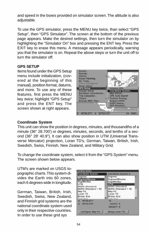
54
and speed in the boxes provided on simulator screen. The altitude is alsoadjustable.
To use the GPS simulator, press the MENU key twice, than select “GPSSetup”, then “GPS Simulator”. The screen at the bottom of the previouspage appears. Make the desired settings, then turn the simulator on byhighlighting the “Simulator On” box and pressing the ENT key. Press theEXIT key to erase this menu. A message appears periodically, warningyou that the simulator is on. Repeat the above steps or turn the unit off toturn the simulator off.
GPS SETUPItems found under the GPS Setupmenu include initialization, (cov-ered at the beginning of thismanual), position format, datums,and more. To use any of thesefeatures, first press the MENUkey twice, highlight “GPS Setup”and press the ENT key. Thescreen shown at right appears.
Coordinate SystemThis unit can show the position in degrees, minutes, and thousandths of aminute (36° 28.700') or degrees, minutes, seconds, and tenths of a sec-ond (36° 28' 40.9"). It can also show position in UTM (Universal Trans-verse Mercator) projection, Loran TD’s, German, Taiwan, British, Irish,Swedish, Swiss, Finnish, New Zealand, and Military Grid.
To change the coordinate system, select it from the “GPS System” menu.The screen shown below appears.
UTM’s are marked on USGS to-pographic charts. This system di-vides the Earth into 60 zones,each 6 degrees wide in longitude.
German, Taiwan, British, Irish,Swedish, Swiss, New Zealand,and Finnish grid systems are thenational coordinate system usedonly in their respective countries.In order to use these grid sys
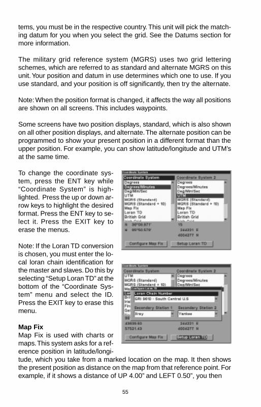
55
tems, you must be in the respective country. This unit will pick the match-ing datum for you when you select the grid. See the Datums section formore information.
The military grid reference system (MGRS) uses two grid letteringschemes, which are referred to as standard and alternate MGRS on thisunit. Your position and datum in use determines which one to use. If youuse standard, and your position is off significantly, then try the alternate.
Note: When the position format is changed, it affects the way all positionsare shown on all screens. This includes waypoints.
Some screens have two position displays, standard, which is also shownon all other position displays, and alternate. The alternate position can beprogrammed to show your present position in a different format than theupper position. For example, you can show latitude/longitude and UTM’sat the same time.
To change the coordinate sys-tem, press the ENT key while“Coordinate System” is high-lighted. Press the up or down ar-row keys to highlight the desiredformat. Press the ENT key to se-lect it. Press the EXIT key toerase the menus.
Note: If the Loran TD conversionis chosen, you must enter the lo-cal loran chain identification forthe master and slaves. Do this byselecting “Setup Loran TD” at thebottom of the “Coordinate Sys-tem” menu and select the ID.Press the EXIT key to erase thismenu.
Map FixMap Fix is used with charts ormaps. This system asks for a ref-erence position in latitude/longi-tude, which you take from a marked location on the map. It then showsthe present position as distance on the map from that reference point. Forexample, if it shows a distance of UP 4.00” and LEFT 0.50”, you then
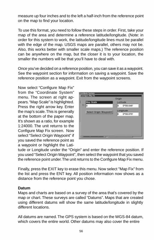
56
measure up four inches and to the left a half-inch from the reference pointon the map to find your location.
To use this format, you need to follow these steps in order. First, take yourmap of the area and determine a reference latitude/longitude. (Note: inorder for this system to work, the latitude/longitude lines must be parallelwith the edge of the map. USGS maps are parallel, others may not be.Also, this works better with smaller scale maps.) The reference positioncan be anywhere on the map, but the closer it is to your location, thesmaller the numbers will be that you’ll have to deal with.
Once you’ve decided on a reference position, you can save it as a waypoint.See the waypoint section for information on saving a waypoint. Save thereference position as a waypoint. Exit from the waypoint screens.
Now select “Configure Map Fix”from the “Coordinate System”menu. The screen at right ap-pears. “Map Scale” is highlighted.Press the right arrow key. Enterthe map’s scale. This is generallyat the bottom of the paper map.It’s shown as a ratio, for example1:24000. The unit returns to theConfigure Map Fix screen. Nowselect “Select Origin Waypoint” ifyou saved the reference point asa waypoint or highlight the Lati-tude or Longitude under the “Origin” and enter the reference position. Ifyou used “Select Origin Waypoint”, then select the waypoint that you savedthe reference point under. The unit returns to the Configure Map Fix menu.
Finally, press the EXIT key to erase this menu. Now select "Map Fix” fromthe list and press the ENT key. All position information now shows as adistance from the reference point you chose.
DatumMaps and charts are based on a survey of the area that’s covered by themap or chart. These surveys are called “Datums”. Maps that are createdusing different datums will show the same latitude/longitude in slightlydifferent locations.
All datums are named. The GPS system is based on the WGS-84 datum,which covers the entire world. Other datums may also cover the entire
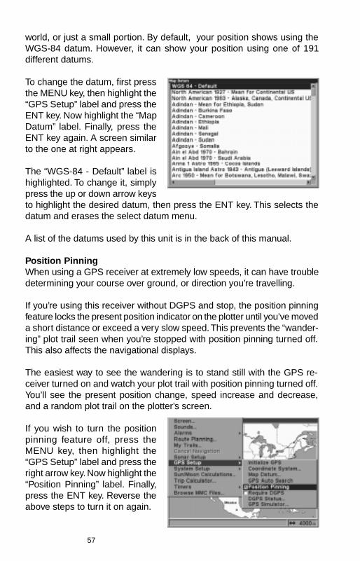
57
world, or just a small portion. By default, your position shows using theWGS-84 datum. However, it can show your position using one of 191different datums.
To change the datum, first pressthe MENU key, then highlight the“GPS Setup” label and press theENT key. Now highlight the “MapDatum” label. Finally, press theENT key again. A screen similarto the one at right appears.
The “WGS-84 - Default” label ishighlighted. To change it, simplypress the up or down arrow keysto highlight the desired datum, then press the ENT key. This selects thedatum and erases the select datum menu.
A list of the datums used by this unit is in the back of this manual.
Position PinningWhen using a GPS receiver at extremely low speeds, it can have troubledetermining your course over ground, or direction you’re travelling.
If you’re using this receiver without DGPS and stop, the position pinningfeature locks the present position indicator on the plotter until you’ve moveda short distance or exceed a very slow speed. This prevents the “wander-ing” plot trail seen when you’re stopped with position pinning turned off.This also affects the navigational displays.
The easiest way to see the wandering is to stand still with the GPS re-ceiver turned on and watch your plot trail with position pinning turned off.You’ll see the present position change, speed increase and decrease,and a random plot trail on the plotter’s screen.
If you wish to turn the positionpinning feature off, press theMENU key, then highlight the“GPS Setup” label and press theright arrow key. Now highlight the“Position Pinning” label. Finally,press the ENT key. Reverse theabove steps to turn it on again.
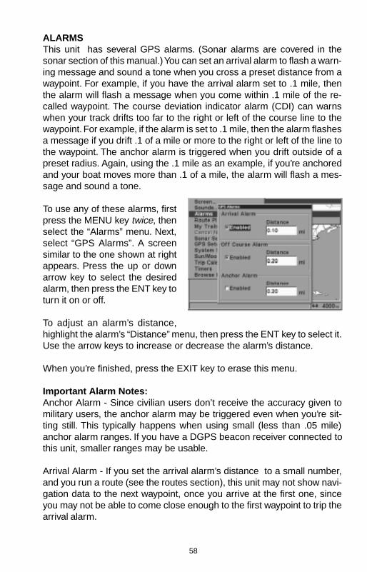
58
ALARMSThis unit has several GPS alarms. (Sonar alarms are covered in thesonar section of this manual.) You can set an arrival alarm to flash a warn-ing message and sound a tone when you cross a preset distance from awaypoint. For example, if you have the arrival alarm set to .1 mile, thenthe alarm will flash a message when you come within .1 mile of the re-called waypoint. The course deviation indicator alarm (CDI) can warnswhen your track drifts too far to the right or left of the course line to thewaypoint. For example, if the alarm is set to .1 mile, then the alarm flashesa message if you drift .1 of a mile or more to the right or left of the line tothe waypoint. The anchor alarm is triggered when you drift outside of apreset radius. Again, using the .1 mile as an example, if you’re anchoredand your boat moves more than .1 of a mile, the alarm will flash a mes-sage and sound a tone.
To use any of these alarms, firstpress the MENU key twice, thenselect the “Alarms” menu. Next,select “GPS Alarms”. A screensimilar to the one shown at rightappears. Press the up or downarrow key to select the desiredalarm, then press the ENT key toturn it on or off.
To adjust an alarm’s distance,highlight the alarm’s “Distance” menu, then press the ENT key to select it.Use the arrow keys to increase or decrease the alarm’s distance.
When you’re finished, press the EXIT key to erase this menu.
Important Alarm Notes:Anchor Alarm - Since civilian users don’t receive the accuracy given tomilitary users, the anchor alarm may be triggered even when you’re sit-ting still. This typically happens when using small (less than .05 mile)anchor alarm ranges. If you have a DGPS beacon receiver connected tothis unit, smaller ranges may be usable.
Arrival Alarm - If you set the arrival alarm’s distance to a small number,and you run a route (see the routes section), this unit may not show navi-gation data to the next waypoint, once you arrive at the first one, sinceyou may not be able to come close enough to the first waypoint to trip thearrival alarm.
59
SONAR TROUBLESHOOTINGIf your unit is not working, or if you need technical help, please use thefollowing troubleshooting section before contacting the factory customerservice department. It may save you the trouble of returning your unit.
Unit won’t turn on:1. Check the power cable’s connection at the unit. Also check the wiring.
2. Make certain the power cable is wired properly. The red wire connectsto the positive battery terminal, black to negative or ground.
3. Check the fuse.
4. Measure the battery voltage at the unit’s power connector. It should beat least 11 volts. If it isn’t, the wiring to the unit is defective, the batteryterminals or wiring on the terminals are corroded, or the battery needscharging.
Unit freezes, locks up, or operates erratically:1. Electrical noise from the boat’s motor, trolling motor, or an accessory
may be interfering with the sonar unit. Rerouting the power and trans-ducer cables away from other electrical wiring on the boat may help.Route the sonar unit’s power cable directly to the battery instead ofthrough a fuse block or ignition switch
2. Inspect the transducer cable for breaks, cuts, or pinched wires.
3. Check both the transducer and power connectors. Make certain bothare securely plugged in to the unit.
Weak bottom echo, digital readings erratic, or no fish signals:1. Make certain transducer is pointing straight down. Clean the face of the
transducer. Oil, dirt, and fuel can cause a film to form on the trans-ducer, reducing its effectiveness. If the transducer is mounted insidethe hull, be sure it is shooting through only one layer of fiberglass andthat it is securely bonded to the hull. Do NOT use RTV silicone rubberadhesive or Marinetex
2. Electrical noise from the boat’s motor can interfere with the sonar. Thiscauses the sonar to automatically increase its Discrimination or noiserejection feature. This can cause the unit to eliminate weaker signalssuch as fish or even structure from the display.
60
3. The water may be deeper than the sonar’s ability to find the bottom. Ifthe sonar can’t find the bottom signal while it’s in the automatic mode,the digital will flash continuously. It may change the range to limits fargreater than the water you are in. If this happens, place the unit in themanual mode, then change the range to a realistic one, (for example,0-100 feet) and increase the sensitivity. As you move into shallowerwater, a bottom signal should appear.
4. Check the battery voltage. If the voltage drops, the unit’s transmitterpower also drops, reducing its ability to find the bottom or targets.
Bottom echo disappears at high speeds or erratic digital reading orweak bottom echo while boat is moving1. The transducer may be in turbulent water. It must be mounted in a
smooth flow of water in order for the sonar to work at all boat speeds.Air bubbles in the water disrupt the sonar signals, interfering with itsability to find the bottom or other targets. The technical term for this isCavitation.
2. Electrical noise from the boat’s motor can interfere with the sonar. Thiscauses the sonar to automatically increase its Discrimination or noiserejection feature. This can cause the unit to eliminate weaker signalssuch as fish or even structure from the display. Try using resistor sparkplugs or routing the sonar unit’s power and transducer cables awayfrom other electrical wiring on the boat.
No fish arches when the Fish ID feature is off:1. Make certain transducer is pointing straight down. This is the most
common problem if a partial arch is displayed.
2. The sensitivity may not be high enough. In order for the unit to display afish arch, it has to be able to receive the fish’s echo from the time itenters the cone until it leaves. If the sensitivity is not high enough, theunit shows the fish only when it is in the center of the cone.
3. Use the Zoom feature. It is much easier to display fish arches whenzoomed in on a small range of water than a large one. For example,you will have much better luck seeing fish arches with a 30 to 60 footrange than a 0 to 60 foot range. This enlarges the targets, allowing thedisplay to show much more detail.
4. The boat must be moving at a slow trolling speed to see fish arches. Ifthe boat is motionless, fish stay in the cone, showing on the screen asstraight horizontal lines.

61
NOISEA major cause of sonar problems is electrical noise. This usually appearson the sonar’s display as random patterns of dots or lines. In severe cases,it can completely cover the screen with black dots, or cause the unit oper-ate erratically, or not at all.
To eliminate or minimize the effects of electrical noise, first try to deter-mine the cause. With the boat at rest in the water, the first thing you shoulddo is turn all electrical equipment on the boat off. Make certain the engineis off, also. Turn the sonar unit on, then turn off ASP (Advanced SignalProcessing). There should be a steady bottom signal on the display. Nowturn on each piece of electrical equipment on the boat and view the effecton the sonar’s display. For example, turn on the bilge pump and view thesonar display for noise. If no noise is present, turn the pump off, then turnon the VHF radio and transmit. Keep doing this until all electrical equip-ment has been turned on, their effect on the sonar display noted, thenturned off.
If you find noise interference from an electrical instrument, trolling motor,pump, or radio, try to isolate the problem. You can usually reroute thesonar unit’s power cable and transducer cable away from the wiring thatis causing the interference. VHF radio antenna cables radiate noise whentransmitting, so be certain to keep the sonar’s wires away from it. You mayneed to route the sonar unit’s power cable directly to the battery to isolateit from other wiring on the boat.
If no noise displays on the sonar unit from electrical equipment, then makecertain everything except the sonar unit is turned off, then start the en-gine. Increase the RPM with the gearshift in neutral. If noise appears onthe display, the problem could be one of three things; spark plugs, alter-nator, or tachometer wiring. Try using resistor spark plugs, alternator fil-ters, or routing the sonar unit’s power cable away from engine wiring.Again, routing the power cable directly to the battery helps eliminate noiseproblems. Make certain to use the in-line fuse supplied with the unit whenwiring the power cable to the battery.
When no noise appears on the sonar unit after all of the above tests, thenthe noise source is probably cavitation. Many novices or persons withlimited experience make hasty sonar installations which function perfectlyin shallow water, or when the boat is at rest. In nearly all cases, the causeof the malfunction will be the location and/or angle of the transducer. Theface of the transducer must be placed in a location that has a smooth flowof water at all boat speeds. Read the transducer instructions for the bestmounting position.
62
LOWRANCE ELECTRONICS, INCFULL ONE-YEAR WARRANTY
“We”, “our”, or “us” refers to LOWRANCE ELECTRONICS, INC, the manufacturer of thisproduct. “You” or “your” refers to the first person who purchases this product as a con-sumer item for personal, family, or household use.
We warrant this product against defects or malfunctions in materials and workmanship,and against failure to conform to this product’s written specifications, all for one year (1)from the date of original purchase by you. WE MAKE NO OTHER EXPRESS WARRANTYOR REPRESENTATION OF ANY KIND WHATSOEVER CONCERNING THIS PRODUCT.Your remedies under this warranty will be available so long as you can show in a reason-able manner that any defect or malfunction in materials or workmanship, or any non-conformity with the product’s written specifications, occurred within one year from the dateof your original purchase, which must be substantiated by a dated sales receipt or salesslip. Any such defect, malfunction, or non-conformity which occurs within one year fromyour original purchase date will either be repaired without charge or be replaced with anew product identical or reasonably equivalent to this product, at our option, within a rea-sonable time after our receipt of the product. If such defect, malfunction, or non-conformityremains after a reasonable number of attempts to repair by us, you may elect to obtainwithout charge a replacement of the product or a refund for the product. THIS REPAIR,REPLACEMENT, OR REFUND (AS JUST DESCRIBED) IS THE EXCLUSIVE REMEDYAVAILABLE TO YOU AGAINST US FOR ANY DEFECT, MALFUNCTION, OR NON-CON-FORMITY CONCERNING THE PRODUCT OR FOR ANY LOSS OR DAMAGE RESULT-ING FROM ANY OTHER CAUSE WHATSOEVER. WE WILL NOT UNDER ANY CIRCUM-STANCES BE LIABLE TO ANYONE FOR ANY SPECIAL, CONSEQUENTIAL, INCIDEN-TAL, OR OTHER INDIRECT DAMAGE OF ANY KIND.
Some states do not allow the exclusion or limitation of incidental or consequential dam-ages, so the above limitations or exclusions may not apply to you.
This warranty does NOT apply in the following circumstances: (1) when the product hasbeen serviced or repaired by anyone other than us, (2) when the product has been con-nected, installed, combined, altered, adjusted, or handled in a manner other than accord-ing to the instructions furnished with the product, (3) when any serial number has beeneffaced, altered, or removed, or (4) when any defect, problem, loss, or damage has re-sulted from any accident, misuse, negligence, or carelessness, or from any failure to pro-vide reasonable and necessary maintenance in accordance with the instructions of theowner’s manual for the product.
We reserve the right to make changes or improvements in our products from time to timewithout incurring the obligation to install such improvements or changes on equipment oritems previously manufactured.
This warranty gives you specific legal rights and you may also have other rights which mayvary from state to state.
REMINDER: You must retain the sales slip or sales receipt proving the date of youroriginal purchase in case warranty service is ever required.
LOWRANCE ELECTRONICS, INC.12000 EAST SKELLY DRIVETULSA, OKLAHOMA 74128
800-324-1356
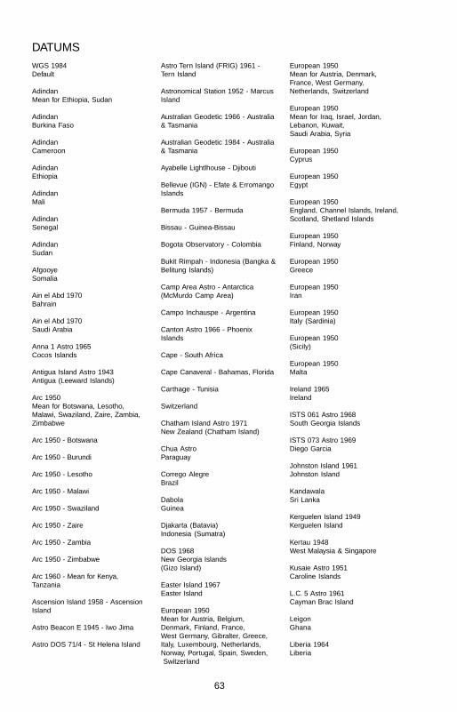
63
DATUMSWGS 1984Default
AdindanMean for Ethiopia, Sudan
AdindanBurkina Faso
AdindanCameroon
AdindanEthiopia
AdindanMali
AdindanSenegal
AdindanSudan
AfgooyeSomalia
Ain el Abd 1970Bahrain
Ain el Abd 1970Saudi Arabia
Anna 1 Astro 1965Cocos Islands
Antigua Island Astro 1943Antigua (Leeward Islands)
Arc 1950Mean for Botswana, Lesotho,Malawi, Swaziland, Zaire, Zambia,Zimbabwe
Arc 1950 - Botswana
Arc 1950 - Burundi
Arc 1950 - Lesotho
Arc 1950 - Malawi
Arc 1950 - Swaziland
Arc 1950 - Zaire
Arc 1950 - Zambia
Arc 1950 - Zimbabwe
Arc 1960 - Mean for Kenya,Tanzania
Ascension Island 1958 - AscensionIsland
Astro Beacon E 1945 - Iwo Jima
Astro DOS 71/4 - St Helena Island
Astro Tern Island (FRIG) 1961 -Tern Island
Astronomical Station 1952 - MarcusIsland
Australian Geodetic 1966 - Australia& Tasmania
Australian Geodetic 1984 - Australia& Tasmania
Ayabelle Lightlhouse - Djibouti
Bellevue (IGN) - Efate & ErromangoIslands
Bermuda 1957 - Bermuda
Bissau - Guinea-Bissau
Bogota Observatory - Colombia
Bukit Rimpah - Indonesia (Bangka &Belitung Islands)
Camp Area Astro - Antarctica(McMurdo Camp Area)
Campo Inchauspe - Argentina
Canton Astro 1966 - PhoenixIslands
Cape - South Africa
Cape Canaveral - Bahamas, Florida
Carthage - Tunisia
Switzerland
Chatham Island Astro 1971New Zealand (Chatham Island)
Chua AstroParaguay
Corrego AlegreBrazil
DabolaGuinea
Djakarta (Batavia)Indonesia (Sumatra)
DOS 1968New Georgia Islands(Gizo Island)
Easter Island 1967Easter Island
European 1950Mean for Austria, Belgium,Denmark, Finland, France,West Germany, Gibralter, Greece,Italy, Luxembourg, Netherlands,Norway, Portugal, Spain, Sweden, Switzerland
European 1950Mean for Austria, Denmark,France, West Germany,Netherlands, Switzerland
European 1950Mean for Iraq, Israel, Jordan,Lebanon, Kuwait,Saudi Arabia, Syria
European 1950Cyprus
European 1950Egypt
European 1950England, Channel Islands, Ireland,Scotland, Shetland Islands
European 1950Finland, Norway
European 1950Greece
European 1950Iran
European 1950Italy (Sardinia)
European 1950(Sicily)
European 1950Malta
Ireland 1965Ireland
ISTS 061 Astro 1968South Georgia Islands
ISTS 073 Astro 1969Diego Garcia
Johnston Island 1961Johnston Island
KandawalaSri Lanka
Kerguelen Island 1949Kerguelen Island
Kertau 1948West Malaysia & Singapore
Kusaie Astro 1951Caroline Islands
L.C. 5 Astro 1961Cayman Brac Island
LeigonGhana
Liberia 1964Liberia

64
LuzonPhilipines(Excluding Mindanao)
LuzonPhilipines (Mindanao)
Mahe 1971Mahe Island
MassawaEthiopia (Eritrea)
MerchichMorocco
Midway Astro 1961Midway Islands
MinnaCameroon
MinnaNigeria
Montserrat Island Astro 1958Montserrat(Leeward Islands)
M’PoralokoGabonNahrwanOman (Masirah Island)
NahrwanSaudi Arabia
NahrwanUnited Arab Emirates
Naparima BWITrinidad & Tobago
North American 1927Mean for Antigua, Barbados,Barbuda, Caicos Islands, Cuba,Dominican Republic, GrandCayman, Jamaica,Turks Islands
North American 1927Mean for Belize, Costa Rica,El Salvador, Guatmala, Honduras,Nicaragua
North American 1927Mean for Canada
North American 1927Mean for CONUS(Continental United States)
North American 1927Mean for CONUS (East ofMississippi River) includingLouisiana, Missouri, Minnesota
North American 1927Mean for CONUS(West of Mississippi River)
DATUMSNorth American 1927Alaska
North American 1927Bahamas(Except San Salvador Island)
North American 1927Bahamas (San Salvador Island)
North American 1927Canada (Alberta, British Columbia)
North American 1927Canada (Manitoba, Ontario)
North American 1927Canada (New Brunswick,Newfoundland, Nova Scotia,Quebec)
North American 1927Canada (Northwest Territories,Saskatchewan)
North American 1927Canada (Yukon)
North American 1927Canal Zone
North American 1927Cuba
North American 1927Greenland (Hayes Peninsula)
North American 1927Mexico
North American 1983Alaska, Canada, CONUS
North American 1983Central America, Mexico
Observaorio Metereo 1939Azores (Corvo & Flores Islands)
Old Egyptian 1907Egypt
Old HawaiianMean for Hawaii, Kauai,Maui, Oahu
Old HawaiianHawaii
Old HawaiianKauai
Old HawaiianMaui
Old HawaiianOahu
OmanOman
Ordinance SurveyGreat Britain 1936 - Mean forEngland, Isle of Man, Scotland,Shetland Islands, Wales
Ordinance SurveyGreat Britian 1936 - England
Ordinance SurveyGreat Britian 1936 - England,Isle of Man, Wales
Ordinance SurveyGreat Britian 1936 - Scotland,Shetland Islands
Ordinance SurveyGreat Britian 1936 - Wales
Pico de las NievesCanary Islands
Pitcairn astro 1967Pitcairn Island
Point 58
Sweden
Santo (DOS)1965 Espirito Santo Island
Sao BrazAzores (Sao Miguel,Santa Maria Islands)
Sapper Hill 1943East Falkland Island
SchwarzeckNambia
Selvagem GrandeSalvage Islands
SGS 85Soviet Geodetic System 1985
South American 1969Mean for Argentina, Bolivia,Brazil, Chile, Colombia, Ecuador,Guyana, Paraguay, Peru,Trinidad & Tobago, Venezuela
South American 1969Argentina
South American 1969Bolivia
South American 1969Brazil
South American 1969Chile
South American 1969Colombia
South American 1969Ecuador
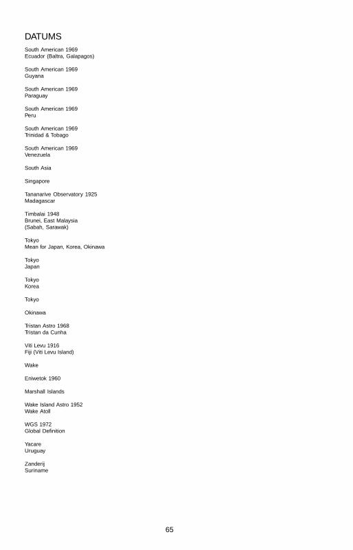
65
DATUMSSouth American 1969Ecuador (Baltra, Galapagos)
South American 1969Guyana
South American 1969Paraguay
South American 1969Peru
South American 1969Trinidad & Tobago
South American 1969Venezuela
South Asia
Singapore
Tananarive Observatory 1925Madagascar
Timbalai 1948Brunei, East Malaysia(Sabah, Sarawak)
TokyoMean for Japan, Korea, Okinawa
TokyoJapan
TokyoKorea
Tokyo
Okinawa
Tristan Astro 1968Tristan da Cunha
Viti Levu 1916Fiji (Viti Levu Island)
Wake
Eniwetok 1960
Marshall Islands
Wake Island Astro 1952Wake Atoll
WGS 1972Global Definition
YacareUruguay
ZanderijSuriname
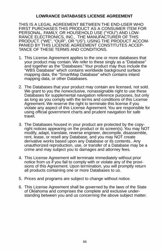
66
LOWRANCE DATABASES LICENSE AGREEMENT
THIS IS A LEGAL AGREEMENT BETWEEN THE END-USER WHOFIRST PURCHASES THIS PRODUCT AS A CONSUMER ITEM FORPERSONAL, FAMILY, OR HOUSEHOLD USE (“YOU”) AND LOW-RANCE ELECTRONICS, INC., THE MANUFACTURER OF THISPRODUCT. (“WE”, “OUR”, OR “US”). USING THE PRODUCT ACCOM-PANIED BY THIS LICENSE AGREEMENT CONSTITUTES ACCEP-TANCE OF THESE TERMS AND CONDITIONS.
1. This License Agreement applies to the one or more databases thatyour product may contain. We refer to these singly as a “Database”and together as the “Databases.” Your product may thus include the“WBS Database” which contains worldwide background surfacemapping data, the “SmartMap Database” which contains inlandmapping data, or other Databases.
2. The Databases that your product may contain are licensed, not sold.We grant to you the nonexclusive, nonassignable right to use theseDatabases for supplemental navigation reference purposes, but onlyas long as you comply with the terms and conditions of this LicenseAgreement. We reserve the right to terminate this license if youviolate any aspect of this License Agreement. You are responsible forusing official government charts and prudent navigation for safetravel.
3. The Databases housed in your product are protected by the copy-right notices appearing on the product or its screen(s). You may NOTmodify, adapt, translate, reverse engineer, decompile, disassemble,rent, lease, or resell any Database, and you may NOT createderivative works based upon any Database or its contents.. Anyunauthorized reproduction, use, or transfer of a Database may be acrime and may subject you to damages and attorney fees.
4. This License Agreement will terminate immediately without priornotice from us if you fail to comply with or violate any of the provi-sions of this Agreement. Upon termination, you will promptly returnall products containing one or more Databases to us.
5. Prices and programs are subject to change without notice.
6. This License Agreement shall be governed by the laws of the Stateof Oklahoma and comprises the complete and exclusive under-standing between you and us concerning the above subject matter.

67
DATABASES LIMITED WARRANTY
“We”, “our”, or “us” refers to Lowrance Electronics, Inc., the manufacturer of thisproduct. “You” or “your” refers to the first person who purchases the product as aconsumer item for personal, family, or household use. The Databases Limited Warrantyapplies to the one or more databases that your product may contain. We refer to each ofthese as a “Database” or together as the “Databases.” Your product may thus include the“WBS Database” which contains worldwide background surface mapping data, the“SmartMap Database” which contains inland mapping data, or other Databases.
We warrant to you that we have accurately compiled, processed, and reproduced theportions of the source material on which the Databases are based. However, we areunder no obligation to provide updates to the Databases, and the data contained in theDatabases may be incomplete when compared to the source material. WE MAKE NOEXPRESS OR IMPLIED WARRANTY OF ANY KIND ABOUT THE ACCURACY OF THESOURCE MATERIAL ITSELF, INCLUDING BUT NOT LIMITED TO IMPLIED WARRAN-TIES OF MERCHANTABILITY OR FITNESS FOR A PARTICULAR PURPOSE.
If there is a defect in any Database, your exclusive remedy shall be, at our option, eithera refund of the price you paid for the product containing the defective Database or areplacement of such product. WE WILL NOT UNDER ANY CIRCUMSTANCES BELIABLE TO ANYONE FOR ANY SPECIAL, CONSEQUENTIAL, INCIDENTAL, OROTHER INDIRECT DAMAGE OF ANY KIND.
Some states do not allow the exclusion or limitation of incidental or consequentialdamages, so the above limitations or exclusions may not apply to you.
This warranty does NOT apply in the following circumstances: (1) when the product hasbeen serviced or repaired by anyone other than us, (2) when the product has beenconnected, installed, combined, altered, adjusted, or handled in a manner other thanaccording to the instructions furnished with the product, (3) when any serial number hasbeen effaced, altered, or removed, or (4) when any defect, problem, loss, or damagehas resulted from any accident, misuse, negligence, or carelessness, or from any failureto provide reasonable and necessary maintenance in accordance with the instructionsof the owner’s manual for the product.
We reserve the right to make changes or improvements in our products from time totime without incurring the obligation to install such improvements or changes onequipment or items previously manufactured.
This warranty gives you specific legal rights and you may also have other rights whichmay vary from state to state.
Your remedies under this warranty will be available so long as you can show in areasonable manner that the defect occurred within one (1) year from the date of youroriginal purchase, and we must receive your warranty claim no later than 30 days aftersuch 1-year period expires. Your claim must be substantiated by a dated sales receipt orsales slip.
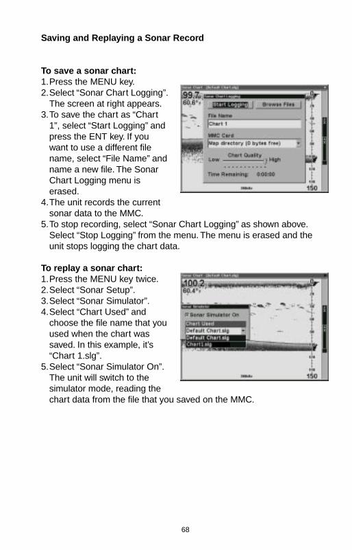
68
Saving and Replaying a Sonar Record
To save a sonar chart:1.Press the MENU key.2.Select “Sonar Chart Logging”.
The screen at right appears.3.To save the chart as “Chart
1”, select “Start Logging” andpress the ENT key. If youwant to use a different filename, select “File Name” andname a new file. The SonarChart Logging menu iserased.
4.The unit records the currentsonar data to the MMC.
5.To stop recording, select “Sonar Chart Logging” as shown above.Select “Stop Logging” from the menu. The menu is erased and theunit stops logging the chart data.
To replay a sonar chart:1.Press the MENU key twice.2.Select “Sonar Setup”.3.Select “Sonar Simulator”.4.Select “Chart Used” and
choose the file name that youused when the chart wassaved. In this example, it’s“Chart 1.slg”.
5.Select “Sonar Simulator On”.The unit will switch to thesimulator mode, reading thechart data from the file that you saved on the MMC.
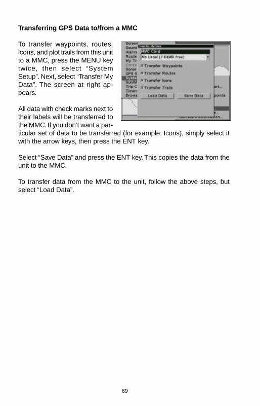
69
Transferring GPS Data to/from a MMC
To transfer waypoints, routes,icons, and plot trails from this unitto a MMC, press the MENU keytwice, then select “SystemSetup”. Next, select “Transfer MyData”. The screen at right ap-pears.
All data with check marks next totheir labels will be transferred tothe MMC. If you don’t want a par-ticular set of data to be transferred (for example: Icons), simply select itwith the arrow keys, then press the ENT key.
Select “Save Data” and press the ENT key. This copies the data from theunit to the MMC.
To transfer data from the MMC to the unit, follow the above steps, butselect “Load Data”.

70
71
How to Obtain Service(Canadian Customers Only)
We back your investment in quality products with quick, expert service and genuineLowrance replacement parts. If you need service or repairs, contact the LowranceFactory Customer Service Department at the toll-free number listed below. A techni-cian may be able to solve the problem and save you the inconvenience of returningyour unit. You will be asked for your unit’s serial number.
800-661-3983800-661-3983800-661-3983800-661-3983800-661-3983905-629-1614905-629-1614905-629-1614905-629-1614905-629-1614
Canada Only.
How to Obtain Service(International Customers Only)
If you need service or repairs, contact the dealer in the country you purchased yourunit.
WARRANTY REPAIR WILL BE HONORED ONLY IN THE COUNTRYUNIT WAS PURCHASED.
Please follow the shipping instructions shown below on this page if you have to mailyour unit to the dealer. For proper testing, repair, and service, send a brief note with theproduct describing the problem. Be sure to include your name, return shipping ad-dress, and a daytime telephone number.
Shipping InformationWhen sending a product for repair, we recommend you do the following:1. Always use the original shipping container and filler material the product was packed
in when shipping your product.
2 Always insure the parcel against damage or loss during shipment. Lowrance doesnot assume responsibility for goods lost or damaged in transit.
3. For proper testing, repair, and service, send a brief note with the productdescribing the problem. Be sure to include your name, return shipping address, anda daytime telephone number.
Accessory Ordering InformationTo order accessories such as power cables or transducers, please contact:1. Your local marine dealer. Most quality dealers that handle marine electronic equip-
ment should be able to assist you with these items. Consult your local telephonedirectory for listings.
2. Canadian customers only can write:Lowrance/Lowrance Canada, 919 Matheson Blvd., E. Mississauga, Ontario L4W2R7
or fax 905-629-3118

72
How to Obtain Service (U.S.A. Only)We back your investment in quality products with quick, expert serviceand genuine Lowrance® replacement parts. If you’re in the United Statesand you have questions, please contact the Factory Customer ServiceDepartment using our toll-free number listed below. You must send theunit to the factory for warranty service or repair. Please call the factorybefore sending the unit. You will be asked for your unit’s serial number (shownabove). Use the following toll-free number:
800-324-1356U.S.A.only. Monday through Friday, except holidays.
Your unit is covered by a full one-year warranty. (See inside for completewarranty details.) If your unit fails and the failure is not covered by theoriginal warranty, Lowrance has a flat-rate repair policy that covers yourunit and accessories packed with the unit at the factory. There is a 180-day warranty on all non-warranty repairs from the factory, which is similarto the original warranty, but is for 180 days rather than one year. For fur-ther details, please call us at the above number.
Remember, non-warranty repairs are subject to Lowrance’s published flat-rate charges and 180-day warranty.
LOWRANCE ELECTRONICS, INC12000 E. SKELLY DRIVE
TULSA, OK 74128800-324-1356
http://www.lowrance.com
LITHO IN U.S.A. 988-0133-49
Accessory Ordering InformationTo order accessories such as power cables or transducers, please con-tact:
1) Your local marine dealer. Most quality dealers that handle marine elec-tronic equipment should be able to assist you with these items. Consultyour local telephone directory for listings.
2) LEI Extras, Inc. P.O. Box 129 Catoosa, OK 74015-0129or call
800-324-0045(USA orders only.)
or see their website at http://www.lei-extras.com
Related Documents