LCWA, ALCPG 2009 A lbuquerque, NM Ivo Polák, FZU, Prague 1 Calibration system of CALICE AHCAL detector Ivo Polák [email protected] 1. Two calibration light distribution systems 2. QRLED driver photoelectron spectra 3. QRLED driver behaviour in strong magnetic field 4. Conclusions

LCWA, ALCPG 2009 Albuquerque, NM Ivo Polák, FZU, Prague1 Calibration system of CALICE AHCAL detector Ivo Polák [email protected] 1.Two calibration light distribution.
Jan 03, 2016
Welcome message from author
This document is posted to help you gain knowledge. Please leave a comment to let me know what you think about it! Share it to your friends and learn new things together.
Transcript

LCWA, ALCPG 2009 Albuquerque, NM
Ivo Polák, FZU, Prague 1
Calibration system of CALICE AHCAL detector
Ivo Polá[email protected]
1. Two calibration light distribution systems2. QRLED driver photoelectron spectra3. QRLED driver behaviour in strong magnetic field4. Conclusions

LCWA, ALCPG 2009 Albuquerque, NM
Ivo Polák, FZU, Prague 2
Flashing UVLED - 2 methods
• Light distributed by notched fibres
• Light distributed directly by microLED to the scintillator - distributed LEDs
Institute of Physics ASCR, Prague, (= FZU)Kobe University
DESY HamburgUNI Wuppertal
smd UVLED

LCWA, ALCPG 2009 Albuquerque, NM
Ivo Polák, FZU, Prague 3
General mechanical concept AHCAL EUDET module

LCWA, ALCPG 2009 Albuquerque, NM
Ivo Polák, FZU, Prague 4
Details of distributed LEDsSmall UV LED, smd size 1206 and 0603
top
bottom
LCWA, ALCPG 2009 Albuquerque, NM
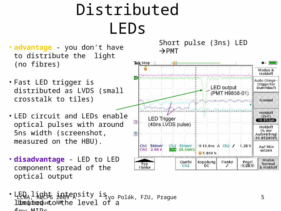
Ivo Polák, FZU, Prague 5
Distributed LEDsShort pulse (3ns) LED PMT
• advantage - you don't have to distribute the light (no fibres)
• Fast LED trigger is distributed as LVDS (small crosstalk to tiles)
• LED circuit and LEDs enable optical
pulses with around 5ns width (screenshot, measured on the HBU).
• disadvantage - LED to LED component spread of the optical output
• LED light intensity is limited to the level of a few MIPs
LCWA, ALCPG 2009 Albuquerque, NM
Ivo Polák, FZU, Prague 6
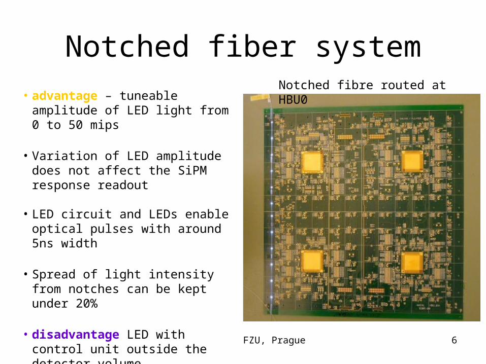
Notched fiber system
• advantage – tuneable amplitude of LED light from 0 to 50 mips
• Variation of LED amplitude does not affect the SiPM response readout
• LED circuit and LEDs enable optical
pulses with around 5ns width
• Spread of light intensity from notches can be kept under 20%
• disadvantage LED with control unit outside the detector volume
• Notched fibre production is not trivial
Notched fibre routed at HBU0

LCWA, ALCPG 2009 Albuquerque, NM
Ivo Polák, FZU, Prague 7
Classic “old style” LED driver
• A few components• Optimizing at Uni Wuppertal by
S. Weber• Original design at DESY FE by
Mathias Reinecke for HBU0 (distributed LEDs) 5ns achieved
• One long Trigger signal is needed

LCWA, ALCPG 2009 Albuquerque, NM
Ivo Polák, FZU, Prague 8
Quasi-Resonant LED driver
• Less RFI• PCB integrated
toroidal inductor (~35nH)
• Fixed pulse-width (~4ns)
LED current 1V => 1A
PIN signal
4ns/div
1App

LCWA, ALCPG 2009 Albuquerque, NM
Ivo Polák, FZU, Prague 99
6-LED QR driver Main Board = QMB6
Consists:
- 6 QR LED drivers
- 2 PIN PD preamps
- CPU + communication module, CANbus
- Voltage regulators
- temperature and voltage monitoring

LCWA, ALCPG 2009 Albuquerque, NM
Ivo Polák, FZU, Prague 10
Single photoelectron spectra with CMBCMB and QRLEDQRLED
CMB in tuning position at AHCAL TB 2007 CERN
QRLed drive SiPM, single p.e. spectra taken at Prague SEP’09
LED light 400nm toLED light 400nm to
SiPM on 5mmSiPM on 5mm sci tilesci tile
NEW
OLD
More info about CMB can be found at:
http://www-hep2.fzu.cz/calice/files/ECFA_Valencia.Ivo_CMB_Devel_nov06.pdf
one of the single p.e. spectra

LCWA, ALCPG 2009 Albuquerque, NM
Ivo Polák, FZU, Prague 11
Setup for taking single p.e. spectra with notched fibre
LED
Sci + SiPMfiber
QMB6Preamp
Notched fibre is laying on scintillator and taped on position.
Light tight box

LCWA, ALCPG 2009 Albuquerque, NM
Ivo Polák, FZU, Prague 12
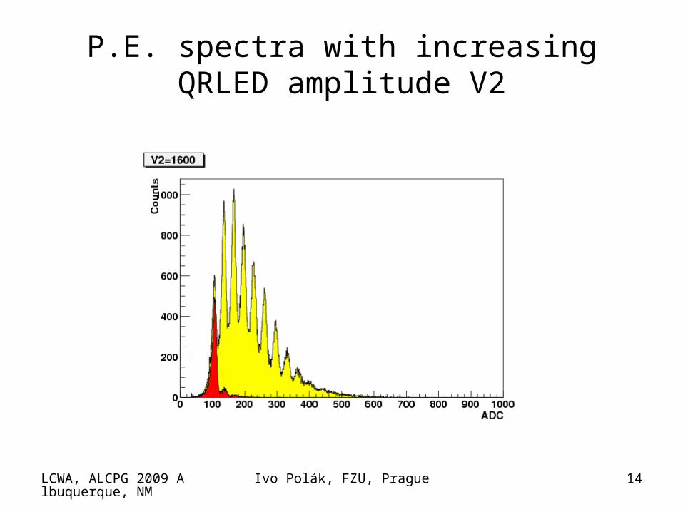
P.E. spectra with increasing QRLED amplitude V2
Pedestal in red is marking its amplitude position.

LCWA, ALCPG 2009 Albuquerque, NM
Ivo Polák, FZU, Prague 13
P.E. spectra with increasing QRLED amplitude V2
LCWA, ALCPG 2009 Albuquerque, NM
Ivo Polák, FZU, Prague 14
P.E. spectra with increasing QRLED amplitude V2

LCWA, ALCPG 2009 Albuquerque, NM
Ivo Polák, FZU, Prague 15
P.E. spectra with increasing QRLED amplitude V2

LCWA, ALCPG 2009 Albuquerque, NM
Ivo Polák, FZU, Prague 16
P.E. spectra with increasing QRLED amplitude V2

LCWA, ALCPG 2009 Albuquerque, NM
Ivo Polák, FZU, Prague 17
P.E. spectra with increasing QRLED amplitude V2
QRLED generates a nice p.e. spectra at
SiPM

LCWA, ALCPG 2009 Albuquerque, NM
Ivo Polák, FZU, Prague 18
QMB6 in superconductive solenoid (magnetic field 0 to 4T) DESY Hamburg, March 2009
• Air core inductor can be sensitive to external magnetic field
• we performed tests of QMB6 in variable magnetic field
• 3 LED flashed into 3 fibre cables• CANbus cable and T-calib +
Power in other cable • The setup was mounted on non-
magnetic wooden paddle, to be moved in/out of solenoid bore.
• Two black end-cups were used to optically screen the setup.
Details of 4T Magnetic test can be found at
http://www-hep2.fzu.cz/calice/files/magnet5.jara_29.pdf

LCWA, ALCPG 2009 Albuquerque, NM
Ivo Polák, FZU, Prague 19
A schema of QMB6 setup in 4T magnet
solenoid
DUT
Magnet control is not shown.

LCWA, ALCPG 2009 Albuquerque, NM
Ivo Polák, FZU, Prague 20
QRLED response to magnetic field 0 ÷ 4T
magnetic fieldtemperature
PIN
4T
2T
0T
APD1 APD2
1.01
1.00

LCWA, ALCPG 2009 Albuquerque, NM
Ivo Polák, FZU, Prague 21
Implications of the observed light intensity on B
• Amplitude decreases linearly with B increase
• The same dependence for ramping up/down (ΔA/A)/ΔB ~ - 0.2%/T
• Assuming magnetic field stability in ILD magnet at the level 5x10⁻⁴ (accuracy of the CMS magnetic field) relative light ampl. change ~ 10-6
• Assuming magn. field homogeneity (CMS solenoid) ~ 0.3T/4T = 7.5% calibration light amplitude variation ≤ 2x10⁻⁴ in the magnet volume
• Compare to typical calibration light variation at the level of 10-1 (optical contacts)
QMB6 has negligible sensitivity to B !!!

LCWA, ALCPG 2009 Albuquerque, NM
Ivo Polák, FZU, Prague 22
Conclusions
• Two optical methods for SiPM calibration in AHCAL under investigation
– Notched fibres
– Distributed LEDs
• For each method UVLED driver has been developed
• QRLED driver has tunable light amplitude and generates clear p.e. spectra
• QRLED driver is not sensitive to magnetic field in the range 0 ÷ 4 T
• Both methods will be tested in HBU0 EUDET prototype

LCWA, ALCPG 2009 Albuquerque, NM
Ivo Polák, FZU, Prague 23
Back up

LCWA, ALCPG 2009 Albuquerque, NM
Ivo Polák, FZU, Prague 24
CMB = Calibration Monitoring Board• CMB used in AHCAL 1m3 prototype• 38 layers in AHCAL detector at at three TB facilities
DESY/CERN/FNAL (2006 to 2009)• One CMB used in Japanese SciECAL detector (TB 2009)• 12 LEDs / 12PIN PD • Steering of amplitude and pulse width of LED by T-calib
and V-calib signals• Rectangular pulse width 2 ÷ 100ns can be tuned• Temperature and voltage readout in slow control, CANbus
control
• Relevant links:• http://www-hep2.fzu.cz/calice/files/
ECFA_Valencia.Ivo_CMB_Devel_nov06.pdf

LCWA, ALCPG 2009 Albuquerque, NM
Ivo Polák, FZU, Prague 25
QRLED Pedestal UVLED SiPM
Related Documents