LCD Television Service Manual Chassis: MT9602 Version: V 1.00 Hisense Visual Technology Co., Ltd. June 10, 2021

Welcome message from author
This document is posted to help you gain knowledge. Please leave a comment to let me know what you think about it! Share it to your friends and learn new things together.
Transcript

LCD Television
Service Manual
Chassis: MT9602
Version: V 1.00
Hisense Visual Technology Co., Ltd.
June 10, 2021
- 2 -
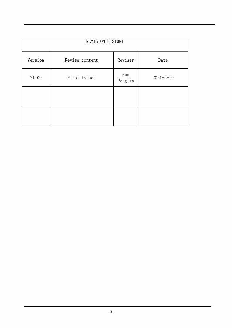
REVISION HISTORY
Version Revise content Reviser Date
V1.00 First issued Sun
Penglin 2021-6-10
- 3 -
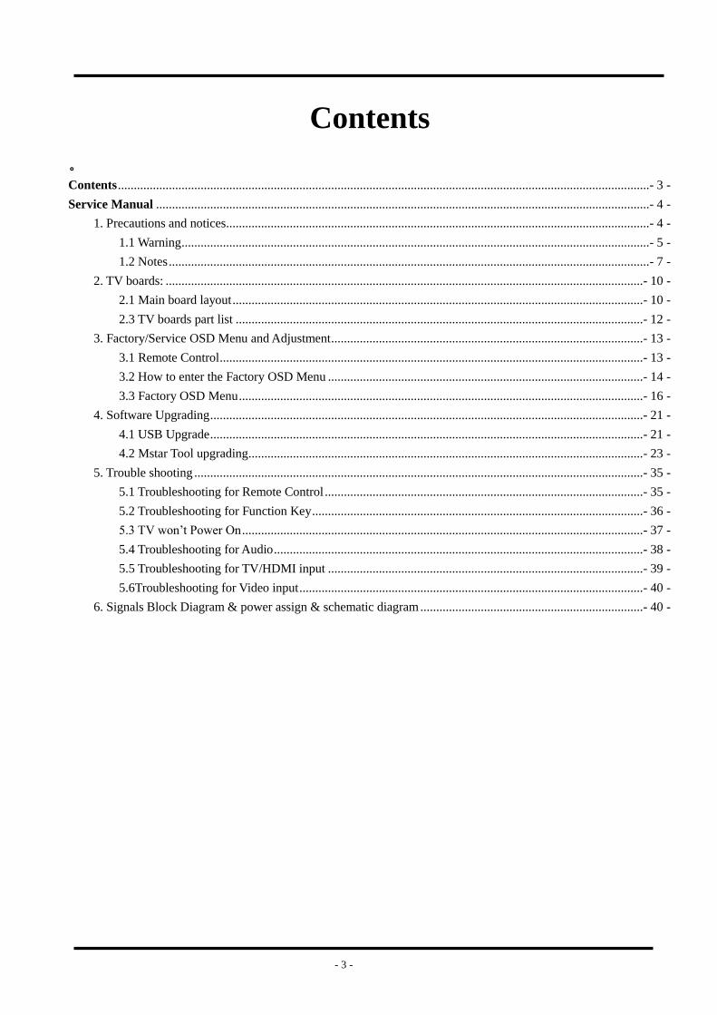
Contents
。
Contents ....................................................................................................................................................................... - 3 -
Service Manual ........................................................................................................................................................... - 4 -
1. Precautions and notices ..................................................................................................................................... - 4 -
1.1 Warning ................................................................................................................................................... - 5 -
1.2 Notes ....................................................................................................................................................... - 7 -
2. TV boards: ...................................................................................................................................................... - 10 -
2.1 Main board layout ................................................................................................................................. - 10 -
2.3 TV boards part list ................................................................................................................................ - 12 -
3. Factory/Service OSD Menu and Adjustment .................................................................................................. - 13 -
3.1 Remote Control ..................................................................................................................................... - 13 -
3.2 How to enter the Factory OSD Menu ................................................................................................... - 14 -
3.3 Factory OSD Menu ............................................................................................................................... - 16 -
4. Software Upgrading ........................................................................................................................................ - 21 -
4.1 USB Upgrade ........................................................................................................................................ - 21 -
4.2 Mstar Tool upgrading ............................................................................................................................ - 23 -
5. Trouble shooting ............................................................................................................................................. - 35 -
5.1 Troubleshooting for Remote Control .................................................................................................... - 35 -
5.2 Troubleshooting for Function Key ........................................................................................................ - 36 -
5.3 TV won’t Power On .............................................................................................................................. - 37 -
5.4 Troubleshooting for Audio .................................................................................................................... - 38 -
5.5 Troubleshooting for TV/HDMI input ................................................................................................... - 39 -
5.6Troubleshooting for Video input ............................................................................................................ - 40 -
6. Signals Block Diagram & power assign & schematic diagram ...................................................................... - 40 -
- 4 -
Service Manual
1. Precautions and notices
BEFORE SERVICING THE LCD TV, READ THE SAFETY PRECAUTIONS IN
THIS MANUAL.
USE ONLY MANUFACTURER SPECIFIED REPLACEMENT PARTS WHEN
SERVICING.
USE OF NON-AUTHORIZED PARTS WILL VOID THE MANUFACTURE'S
WARRANTY
Proper service and repair is important to the safe, reliable operation of all Hisense
Equipment. The service procedures recommended by Hisense and described in this
Service Guide are effective methods of performing service operations. Some of these
service operations require the use of tools specially designed for the purpose. The special
tools should be used when and as recommended.
It is important to note that this manual contains various CAUTIONS and NOTICES
which should be carefully read in order to minimize the risk of personal injury to service
personnel. The possibility exists that improper service methods may damage the
equipment and pose risk of personal injury
. It is also important to understand that these CAUTIONS and NOTICES ARE NOT
EXHAUSTIVE. Service should only be performed by an experienced electronics
techician trained in the proper Television safety and service methods and procedures
- 5 -
Hereafter throughout this manual.
1.1 Warning
1.1.1
Critical components having special safety characteristics are identified with a by the
Ref. No. in the parts list. Use of non-manufacturer's recommended parts may create
shock, fire, or other hazards. Under no circumstances should the original design be
modified or altered without written permission from RCA. Hisense Eassumes no
liability, express or implied, arising out of any unauthorized modification of design.
Servicetech assumes all liability.
1.1.2.
All ICs and many other semiconductors are susceptible to electrostatic discharges (ESD).
Careless handling during repair can reduce life drastically. When repairing, be sure to
use anti-static table mats and properly use a grounding wrist stra. Keep components and
tools also at this same potential.
IMPORTANT:
Always disconnect the power cord from AC outlet before replacing parts or modules.
1.1.3
To prevent electrical shock, use only a properly grounded 3 prong outlet or extension
cord.
1.1.4

- 6 -
When replacement parts are required, be sure to use replacement parts specified by the
manufacturer or have the same characteristics as the original part. Unauthorized
substitutions may result in fire, electric shock, or other hazards and will void the
manufacturer's warranty.
1.1.5
Safety regulations require that after a repair the set must be returned in its original
condition. In addition, prior to closing set, check that:
-Note:
>All wire harnesses and flex cables are properly routed and secured with factory tape
and/or mounted cable clamps.
> All cables and connectors are properly insulated and do not have any bare wires/lead
exposed
1.1.6
(1) Do not supply a voltage higher than that specified to this product. This may
damage the product and may cause a fire.
(2) Do not use this product:
> High humidity areas
> In an area where any water could enter or splash into the unit.
High humidity and water could damage the product and cause fire.
(3) If a foreign substance (such as water, metal, or liquid) gets inside the panel
- 7 -
module, immediately turn off the power. Continuing to use the product may cause fire
or electric shock.
(4) If the product emits smoke, and abnormal smell, or makes an abnormal sound,
immediately turn off the power. Continuing to use the product, it may cause fire or
electric shock.
(5) Do not pull out or insert the power cable from/to an outlet with wet hands. It may
cause electric shock.
(6) Do not damage or modify the power cable. It may cause fire or electric shock.
(7) If the power cable is damaged, or if the connector is loose, do not use the product:
otherwise, this can lead to fire or electric shock.
(8) If the power connector or the connector of the power cable becomes dirty or dusty,
wipe it with a dry cloth. Otherwise, this can lead to fire.
(9) Use only with the cart, stand, tripod, bracket, or table specified by the manufacturer,
or sold with the apparatus. When a cart is used, use caution when moving the
cart/apparatus combination to avoid injury from tip-over
1.2 Notes
Notes on Safe Handling of the LCD panel and during service
The work procedures shown with the Note indication are important for ensuring the
safety of the product and the servicing work. Be sure to follow these instructions.
• Before starting the work, secure a sufficient working space.
• At all times other than when adjusting and checking the product, be sure to turn OFF
- 8 -
the POWER Button and disconnect the power cable from the power source of the TV
during servicing.
• To prevent electric shock and breakage of PC board, start the servicing work at least 30
seconds after the main power has been turned off. Especially when installing and
removing the power board, start servicing at least 2 minutes after the main power has
been turned off.
• While the main power is on, do not touch any parts or circuits other than the ones
specified. If any connection other than the one specified is made between the measuring
equipment and the high voltage power supply block, it can result in electric shock or
may trip the main circuit breaker When installing the LCD module in, and removing it
from the packing carton, be sure to have at least two persons perform the work.
• When the surface of the panel comes into contact with the cushioning materials, be
sure to confirm that there is no foreign matter on top of the cushioning materials before
the surface of the panel comes into contact with the cushioning materials. Failure to
observe this precaution may result in, the surface of the panel being scratched by foreign
matter.
• Be sure to handle the circuit board by holding the large parts as the heat sink or
transformer. Failure to observe this precaution may result in the occurrence of an
abnormality in the soldered areas.
• Do not stack the circuit boards. Failure to observe this precaution may result in
problems resulting from scratches on the parts, the deformation of parts, and
- 9 -
short-circuits due to residual electric charge.
• Perform a safety check when servicing is completed. Verify that the peripherals of the
serviced points have not undergone any deterioration during servicing. Also verify that
the screws, parts and cables removed for servicing purposes have all been returned to
their proper locations in accordance with the original setup.
The lightning flash with arrowhead symbol, within an equilateral triangle is
intended to alert the user to the presence of uninsulated dangerous voltage within the
products enclosure that may be of sufficient magnitude to constitute a risk of electric
shock.
The exclamation point within an equilateral triangle is intended to alert the
service personnel to important safety information in the service literature. .
- 10 -
2. TV boards:
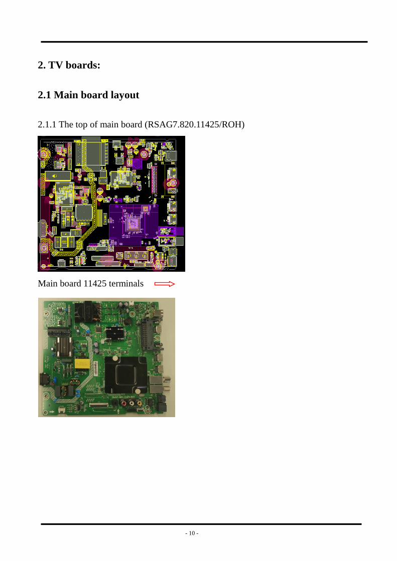
2.1 Main board layout
2.1.1 The top of main board (RSAG7.820.11425/ROH)
Main board 11425 terminals
- 11 -
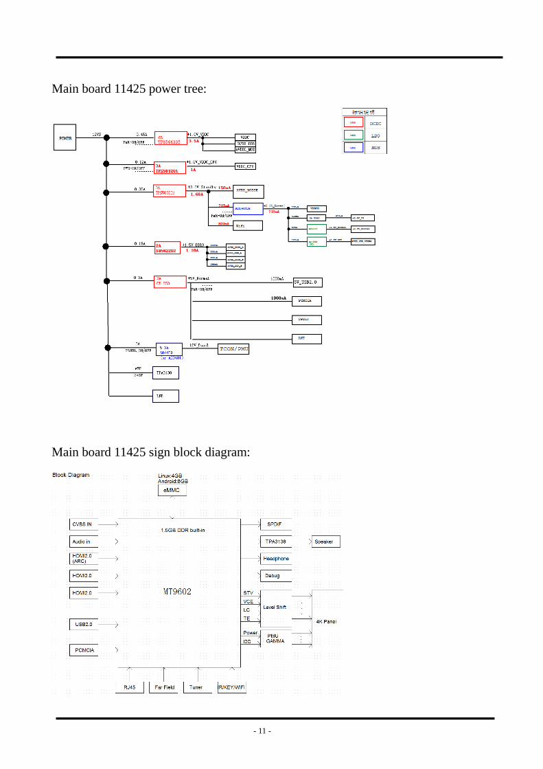
Main board 11425 power tree:
Main board 11425 sign block diagram:
- 12 -
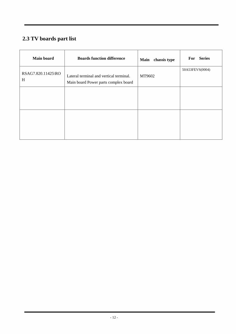
2.3 TV boards part list
Main board Boards function difference
Main chassis type For Series
RSAG7.820.11425\RO
H
Lateral terminal and vertical terminal.
Main board Power parts complex board
MT9602
50A53FEVS(0004)
- 13 -
3. Factory/Service OSD Menu and Adjustment
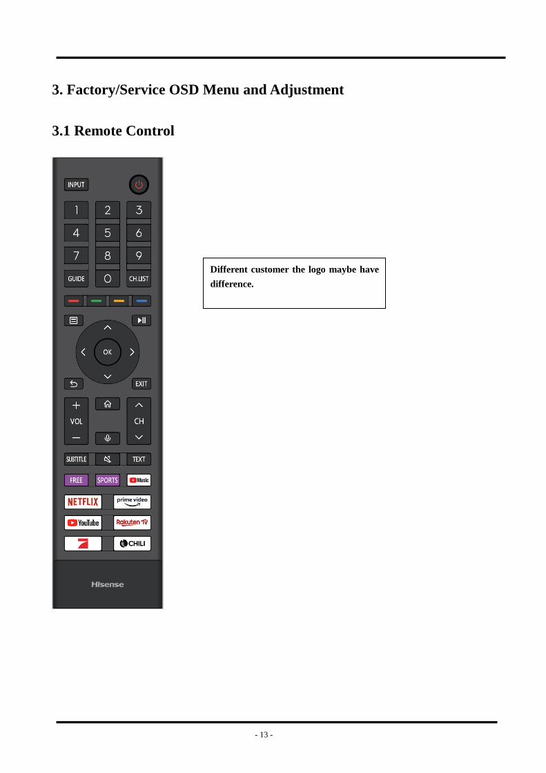
3.1 Remote Control
Different customer the logo maybe have
difference.
- 14 -
3.2 How to enter the Factory OSD Menu
. With user’s RC
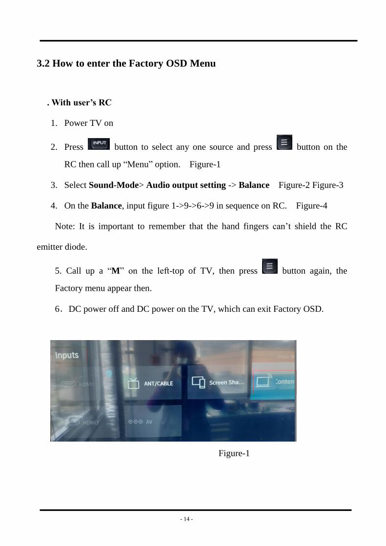
1. Power TV on
2. Press button to select any one source and press button on the
RC then call up “Menu” option. Figure-1
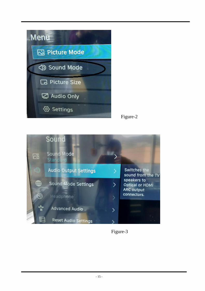
3. Select Sound-Mode> Audio output setting -> Balance Figure-2 Figure-3
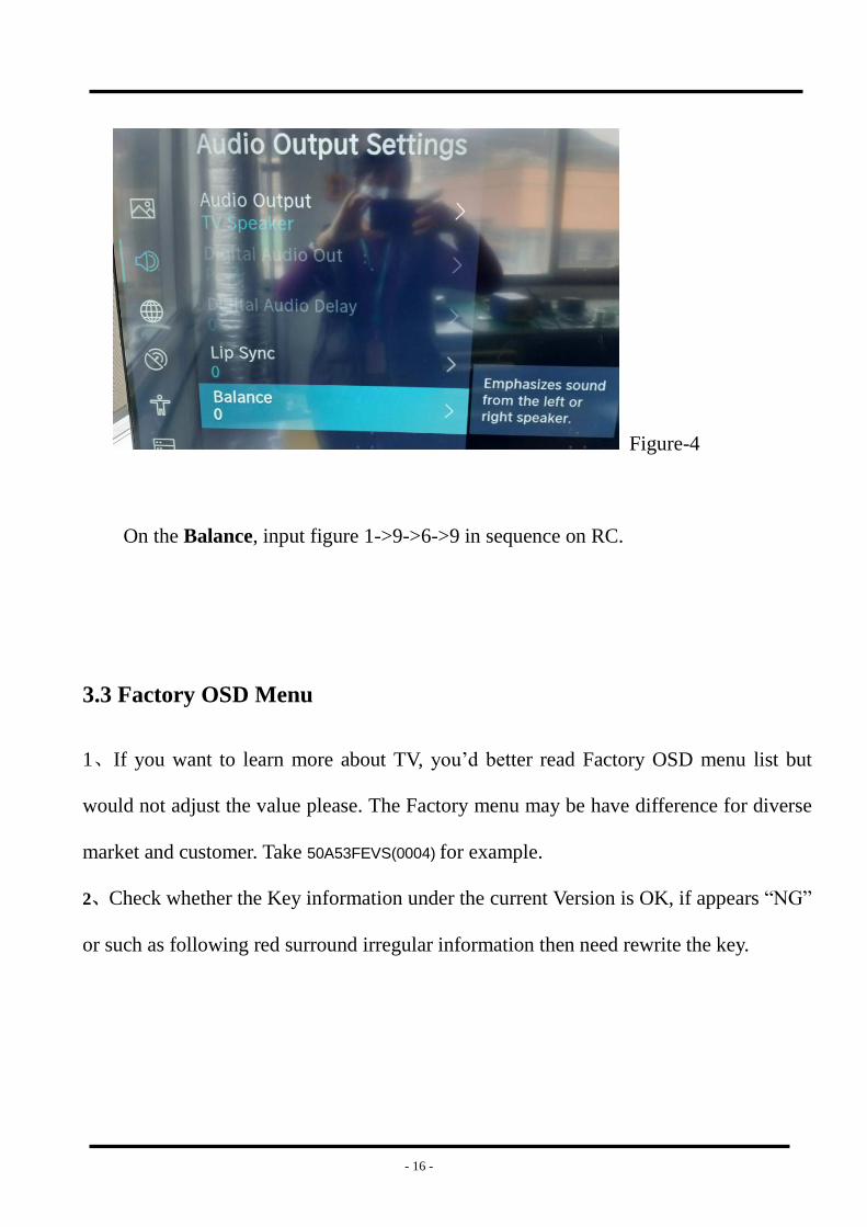
4. On the Balance, input figure 1->9->6->9 in sequence on RC. Figure-4
Note: It is important to remember that the hand fingers can’t shield the RC
emitter diode.
5. Call up a “M” on the left-top of TV, then press button again, the
Factory menu appear then.
6.DC power off and DC power on the TV, which can exit Factory OSD.
Figure-1
- 15 -
Figure-2
Figure-3
- 16 -
Figure-4
On the Balance, input figure 1->9->6->9 in sequence on RC.
3.3 Factory OSD Menu
1、If you want to learn more about TV, you’d better read Factory OSD menu list but
would not adjust the value please. The Factory menu may be have difference for diverse
market and customer. Take 50A53FEVS(0004) for example.
2、Check whether the Key information under the current Version is OK, if appears “NG”
or such as following red surround irregular information then need rewrite the key.

- 17 -
- 18 -
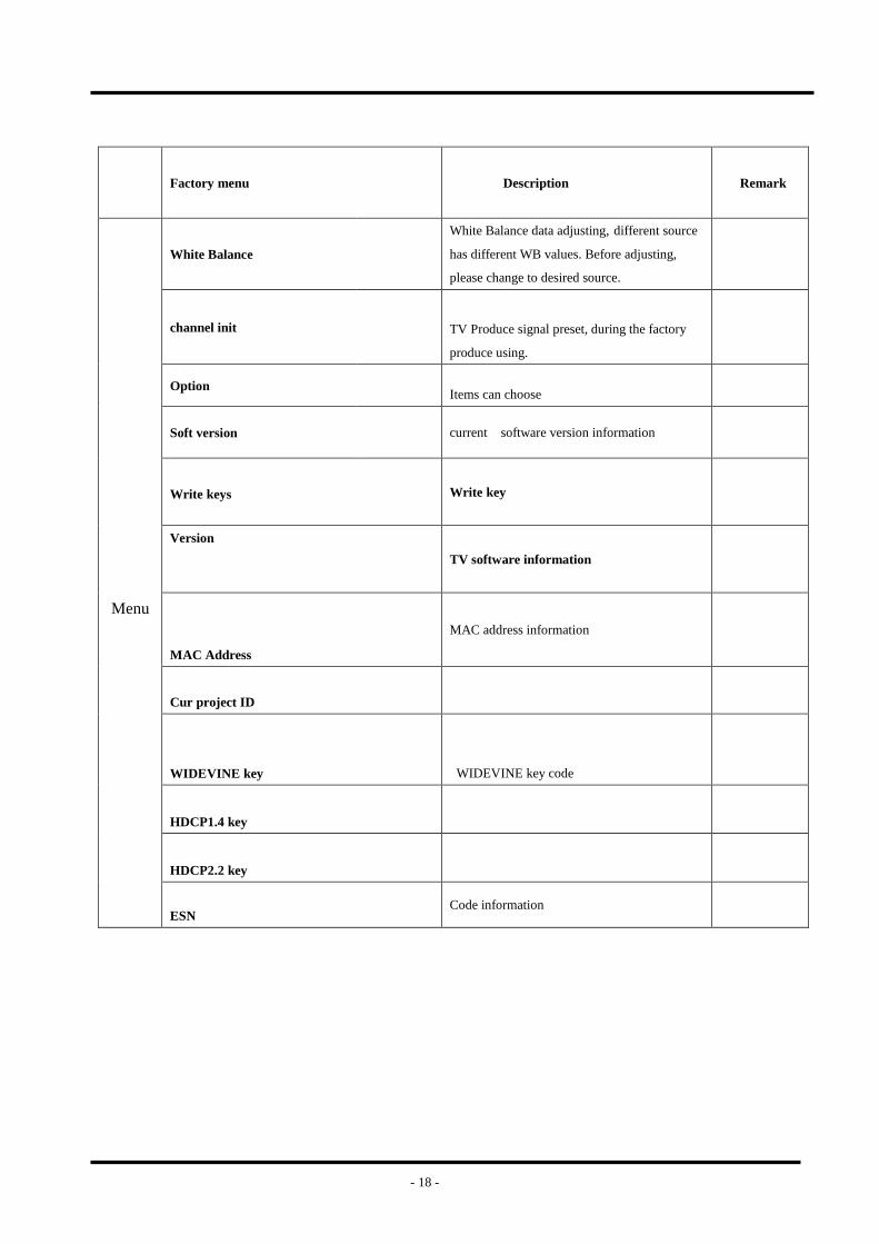
Factory menu
Description
Remark
Menu
White Balance
White Balance data adjusting, different source
has different WB values. Before adjusting,
please change to desired source.
channel init
TV Produce signal preset, during the factory
produce using.
Option
Items can choose
Soft version
current software version information
Write keys Write key
Version
TV software information
MAC Address
MAC address information
Cur project ID
WIDEVINE key
WIDEVINE key code
HDCP1.4 key
HDCP2.2 key
ESN Code information
- 19 -
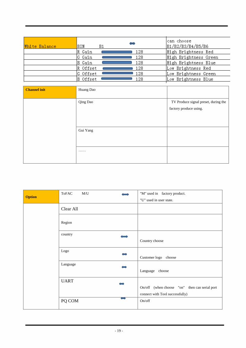
Channel init Huang Dao
Qing Dao TV Produce signal preset, during the
factory produce using.
Gui Yang
……
Option ToFAC M/U "M" used in factory product.
"U" used in user state.
Clear All
Region
country
Country choose
Logo
Customer logo choose
Language
Language choose
UART
On/off (when choose "on" then can serial port
connect with Tool successfully)
PQ COM On/off

- 20 -
Write keys
MAC
If MAC key code lost, you can write.
HDCP2.2
If HDCP key code lost, you can write .
HDCP1.4
If HDCP key code lost, you can write .
Netflix
If Netflix key code lost, you can write .
Widevine If Widevine key code lost, you can write .
Note:
The Factory menu may be have difference for diverse market and customer, above Factory
menu only for reference.
The factory menu data varies according to different sources. Incase changing the factory data by error, you can
choose to “Clear Unprotectly”, by which you can resume the default value.
To clean the EEPROM:
a. Select the item “Option”--“Clear all” in Factory mode.
b. Press button to clear the EEPROM data.
c. Close the OSD menu after 5 seconds.
d. Restart the TV.
e Also the Keys information must been checked, if appear “NG”, then must rewrite key code.

- 21 -
4. Software Upgrading
4.1 USB Upgrade
Main software upgrade directly with USB
The main software can be upgraded with USB disk. It includes two modes: user mode、 factory mode.
Take 50A53FEVS(0004) for example.
4.1.1 TV in user mode:
a. Decompress MTK_DEV_US_pkg_YYYYMMDD.tar.gz (YYYYMMDD is the year/month/day/hour/minute
when the software is being built, such as MTK_DEV_US_(4K_)pkg_20200321.tar.gz), then change
usb_XXX.bin file name to “MstarUpgrade.bin” and the bin file to the USB root directory. Please make sure
there are no other “*.bin” files in the root directory of USB disk.
b. AC power off the TV, insert the USB disk, AC power on and long press the “power” key . If “upgrading
software not turn off……” is shown on TV, it means TV successfully enters upgrading status. Upgrade process
bar will indicate the progress. It needs about 8 minutes to complete the whole software upgrade.
c. After upgrade, TV can automatically reboot.
d. Enter the Factory OSD Menu to check the main software version, and then choose “option”“Clear all” to do
clean up.
4.1.2 TV in factory mode:
a. If TV is in Factory mode, only have difference from chapter 4.1.1 b. as following. others are same.
b. TV is in factory mode, only AC power off TV and insert the USB disk, next AC power on, TV can identify
automatically to update, till call up “upgrading software not turn off……” interface, Upgrade process bar will
indicate the progress.ni
4.1.3 If the above USB upgrade methods fail, you can use serial “cu” to update.
4.1.4 When upgrade successfully, We must ensure the TV mode of running correctly.
Paths: Factory MENU
Once choose another TV mode, must AC power off and power on the TV to reboot.
- 22 -
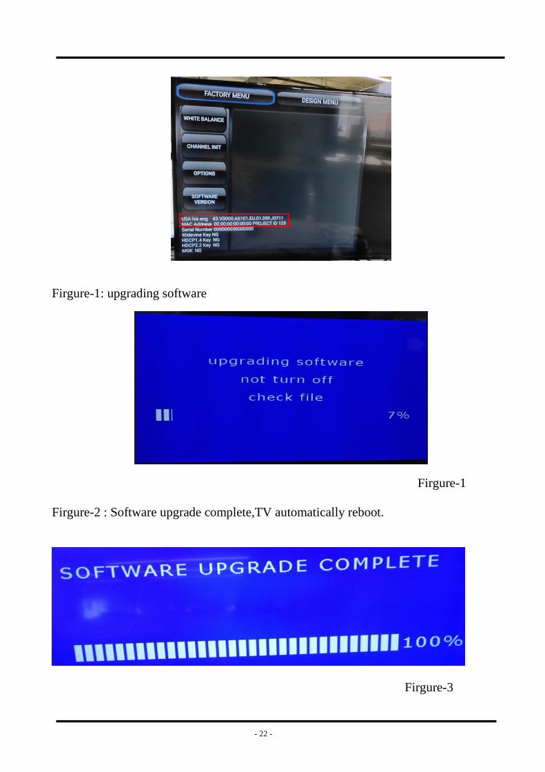
Firgure-1: upgrading software
Firgure-1
Firgure-2 : Software upgrade complete,TV automatically reboot.
Firgure-3
- 23 -
4.2 Mstar Tool upgrading
If USB upgrades failure, TV crashed and SecureCRT no print message. Repairer must read IC device
ID code 、 decipher& burn the Mboot program the EMMC flash first. then USB disk to upgrade
the“upgrade_loader_no_tvcertificate.pkg “file.
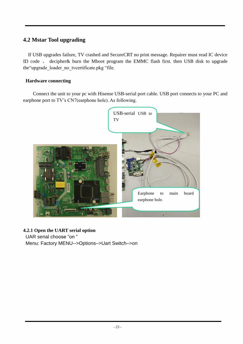
Hardware connecting
Connect the unit to your pc with Hisense USB-serial port cable. USB port connects to your PC and
earphone port to TV’s CN7(earphone hole). As following.
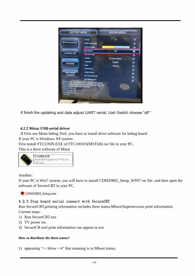
4.2.1 Open the UART serial option
UAR serial choose “on “
Menu: Factory MENU-->Options–>Uart Switch–>on
Earphone to main board
earphone hole.
USB-serial USB to
TV
- 24 -
If finish the updating and data adjust UART serial, Uart Switch choose “off “
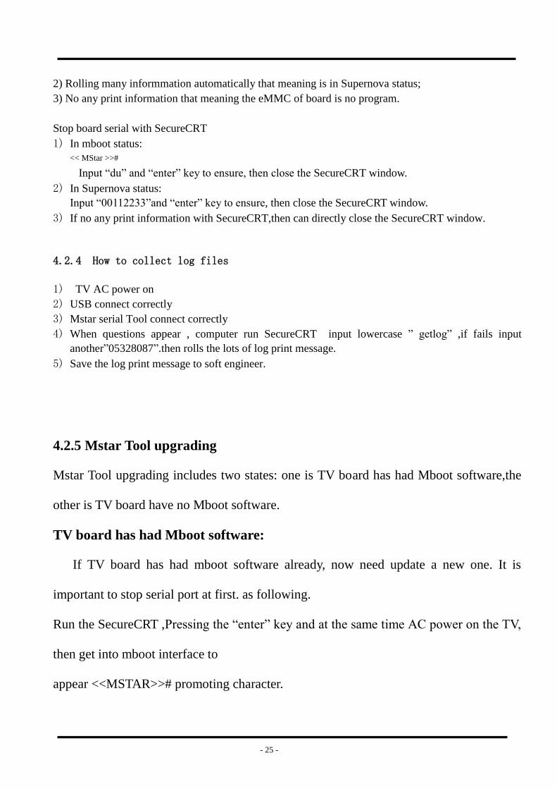
4.2.2 Mstar USB-serial driver
If First use Mstar bebug Tool, you have to install drive software for bebug board.
If your PC is Windows XP system:
First install FTCUNIN.EXE of FTC100103(MSTAR) rar file in your PC.
This is a drive software of Mstar
Another:
If your PC is Win7 system, you will have to install CDM20802_Setup_WIN7 rar file,and then open the
software of SecureCRT in your PC.
4.2.3 Stop board serial connect with SecureCRT
Run SecureCRT,printing information includes three status:Mboot\Supernova\no print information.
Current steps:
1) Run SecureCRT.exe
2) TV power on.
3) SecureCR tool print information can appear or not.
How to distribute the three status?
1) appearing “<< MStar >>#” that meaning is in Mboot status;
- 25 -
2) Rolling many informmation automatically that meaning is in Supernova status;
3) No any print information that meaning the eMMC of board is no program.
Stop board serial with SecureCRT
1) In mboot status:
<< MStar >>#
Input “du” and “enter” key to ensure, then close the SecureCRT window.
2) In Supernova status:
Input “00112233”and “enter” key to ensure, then close the SecureCRT window.
3) If no any print information with SecureCRT,then can directly close the SecureCRT window.
4.2.4 How to collect log files
1) TV AC power on
2) USB connect correctly
3) Mstar serial Tool connect correctly
4) When questions appear , computer run SecureCRT input lowercase ” getlog” ,if fails input
another”05328087”.then rolls the lots of log print message.
5) Save the log print message to soft engineer.
4.2.5 Mstar Tool upgrading
Mstar Tool upgrading includes two states: one is TV board has had Mboot software,the
other is TV board have no Mboot software.
TV board has had Mboot software:
If TV board has had mboot software already, now need update a new one. It is
important to stop serial port at first. as following.
Run the SecureCRT ,Pressing the “enter” key and at the same time AC power on the TV,
then get into mboot interface to
appear <<MSTAR>># promoting character.
- 26 -
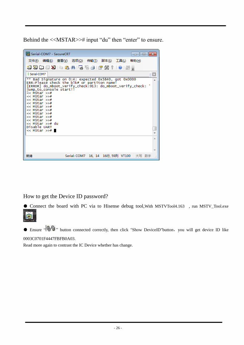
Behind the <<MSTAR>># input “du” then “enter” to ensure.
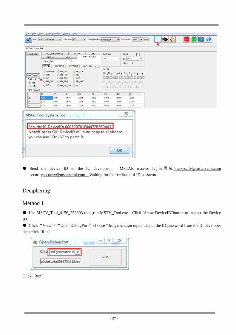
How to get the Device ID password?
● Connect the board with PC via to Hisense debug tool,With MSTVTool4.163 , run MSTV_Tool.exe
● Ensure “ ” button connected correctly, then click "Show DeviceID"button,you will get device ID like
0003C0701F4447FBFB0A03.
Read more again to contrast the IC Device whether has change.
- 27 -
● Send the device ID to the IC developer , MSTAR max-sc lv( 吕 思 成 )[email protected]
[email protected] Waiting for the feedback of ID password.
Deciphering
Method 1
● Use MSTV_Tool_4156_258303 tool ,run MSTV_Tool.exe,Click "Show DeviceID"button to inspect the Device
ID.
● Click “View”->“Open DebugPort” choose “3rd generation input”,input the ID password from the IC developer
then click “Run”
Click” Run”
- 28 -
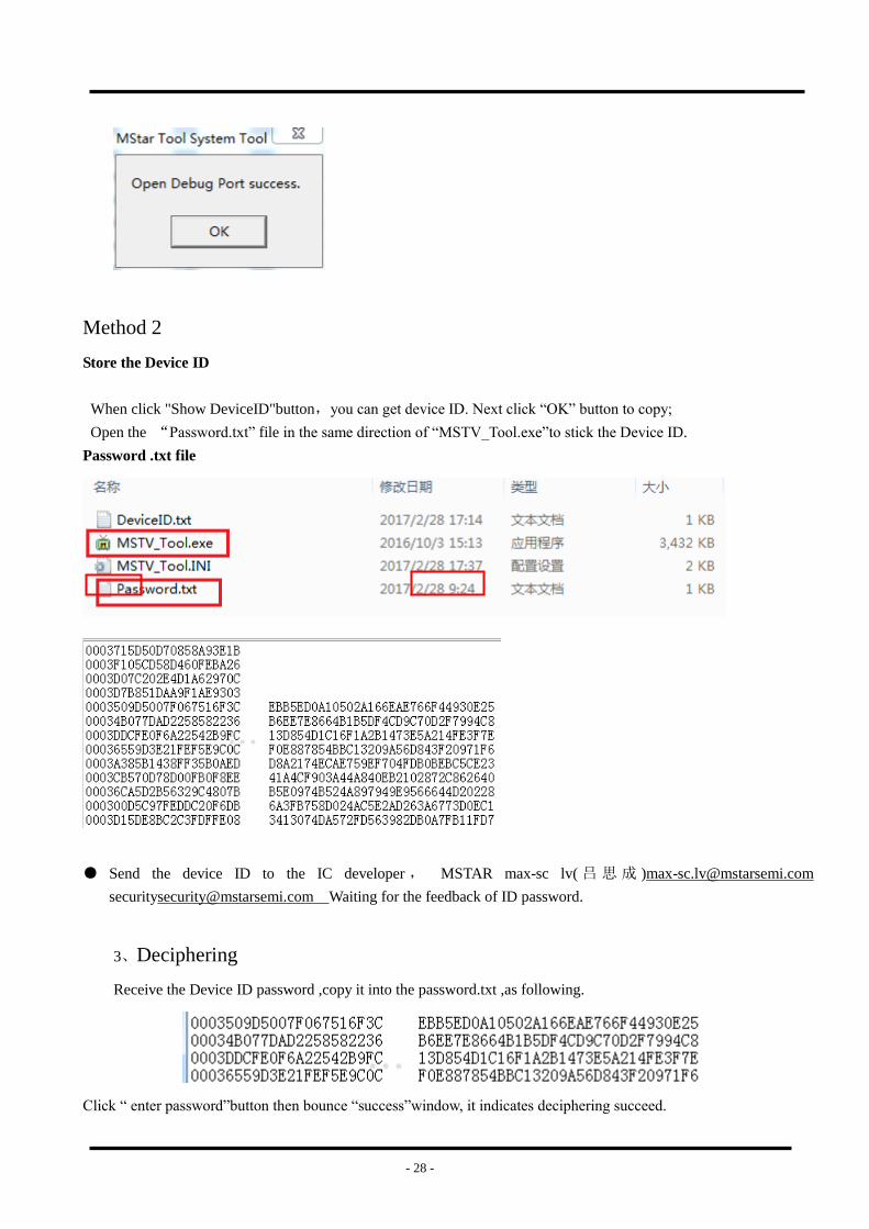
Method 2
Store the Device ID
When click "Show DeviceID"button,you can get device ID. Next click “OK” button to copy;
Open the “Password.txt” file in the same direction of “MSTV_Tool.exe”to stick the Device ID.
Password .txt file
● Send the device ID to the IC developer , MSTAR max-sc lv( 吕 思 成 )[email protected]
[email protected] Waiting for the feedback of ID password.
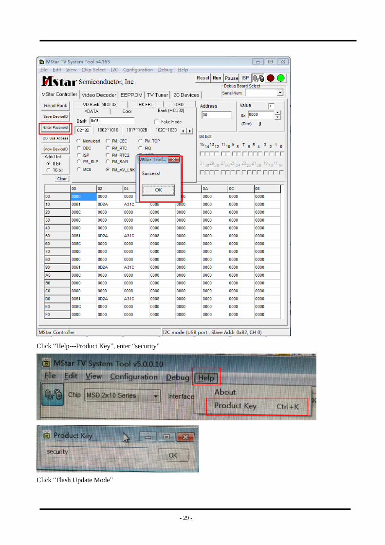
3、Deciphering
Receive the Device ID password ,copy it into the password.txt ,as following.
Click “ enter password”button then bounce “success”window, it indicates deciphering succeed.
- 29 -
Click “Help---Product Key”, enter “security”
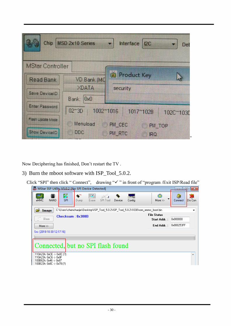
Click “Flash Update Mode”
- 30 -
”
Now Deciphering has finished, Don’t restart the TV .
3) Burn the mboot software with ISP_Tool_5.0.2.
Click “SPI” then click “ Connect”, drawing “ ” in front of “program /Exit ISP/Read file”
- 31 -
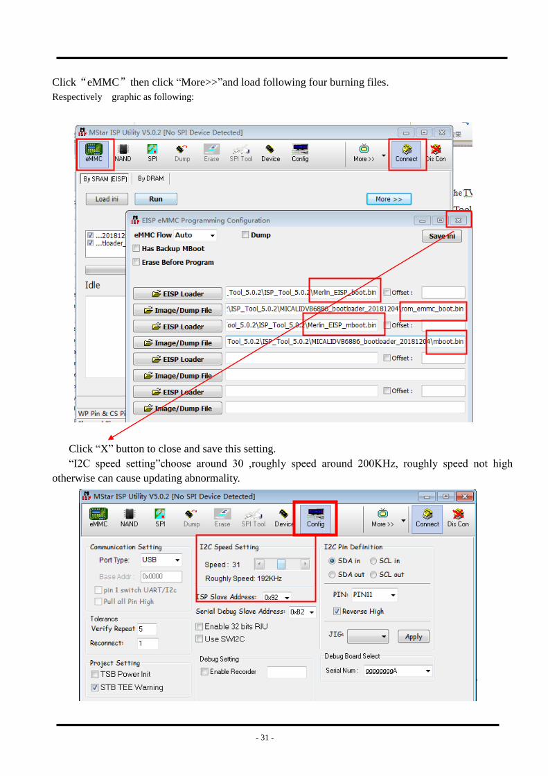
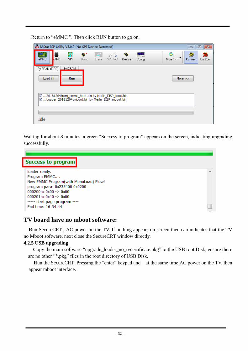
Click“eMMC”then click “More>>”and load following four burning files.
Respectively graphic as following:
Click “X” button to close and save this setting.
“I2C speed setting”choose around 30 ,roughly speed around 200KHz, roughly speed not high
otherwise can cause updating abnormality.
- 32 -
Return to “eMMC ”. Then click RUN button to go on.
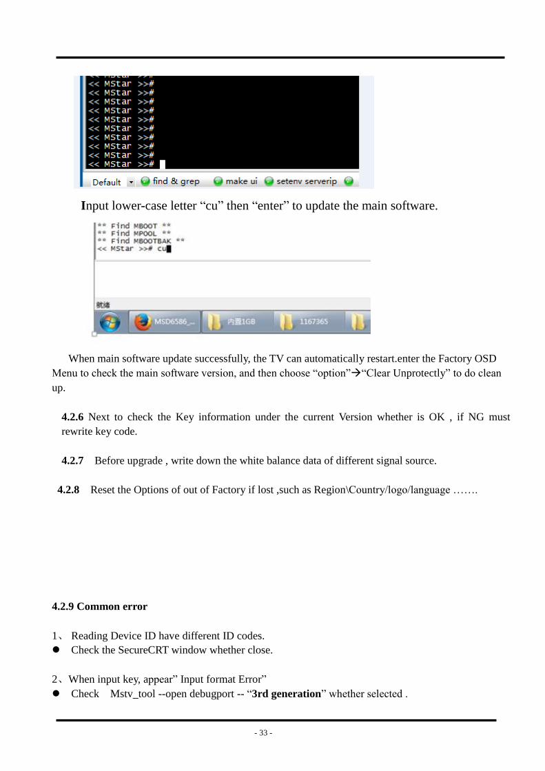
Waiting for about 8 minutes, a green “Success to program” appears on the screen, indicating upgrading
successfully.
TV board have no mboot software:
Run SecureCRT , AC power on the TV. If nothing appears on screen then can indicates that the TV
no Mboot software, next close the SecureCRT window directly.
4.2.5 USB upgrading
Copy the main software “upgrade_loader_no_tvcertificate.pkg” to the USB root Disk, ensure there
are no other “*.pkg” files in the root directory of USB Disk.
Run the SecureCRT ,Pressing the “enter” keypad and at the same time AC power on the TV, then
appear mboot interface.
- 33 -
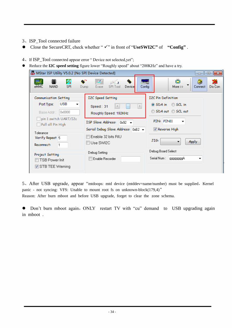
Input lower-case letter “cu” then “enter” to update the main software.
When main software update successfully, the TV can automatically restart.enter the Factory OSD
Menu to check the main software version, and then choose “option”“Clear Unprotectly” to do clean
up.
4.2.6 Next to check the Key information under the current Version whether is OK , if NG must
rewrite key code.
4.2.7 Before upgrade , write down the white balance data of different signal source.
4.2.8 Reset the Options of out of Factory if lost ,such as Region\Country/logo/language …….
4.2.9 Common error
1、 Reading Device ID have different ID codes.
Check the SecureCRT window whether close.
2、When input key, appear” Input format Error”
Check Mstv_tool --open debugport -- “3rd generation” whether selected .
- 34 -
3、ISP_Tool connected failure
Close the SecureCRT, check whether “ ” in front of “UseSWI2C” of “Config” .
4、If ISP_Tool connected appear error “ Device not selected,yet”;
Reduce the I2C speed setting figure lower “Roughly speed” about “200KHz” and have a try.
5、After USB upgrade, appear “mtdoops: mtd device (mtddev=name/number) must be supplied,Kernel
panic - not syncing: VFS: Unable to mount root fs on unknown-block(179,4)”
Reason: After burn mboot and before USB upgrade, forget to clear the zone schema.
Don’t burn mboot again,ONLY restart TV with “cu” demand to USB upgrading again
in mboot .
- 35 -
5. Trouble shooting
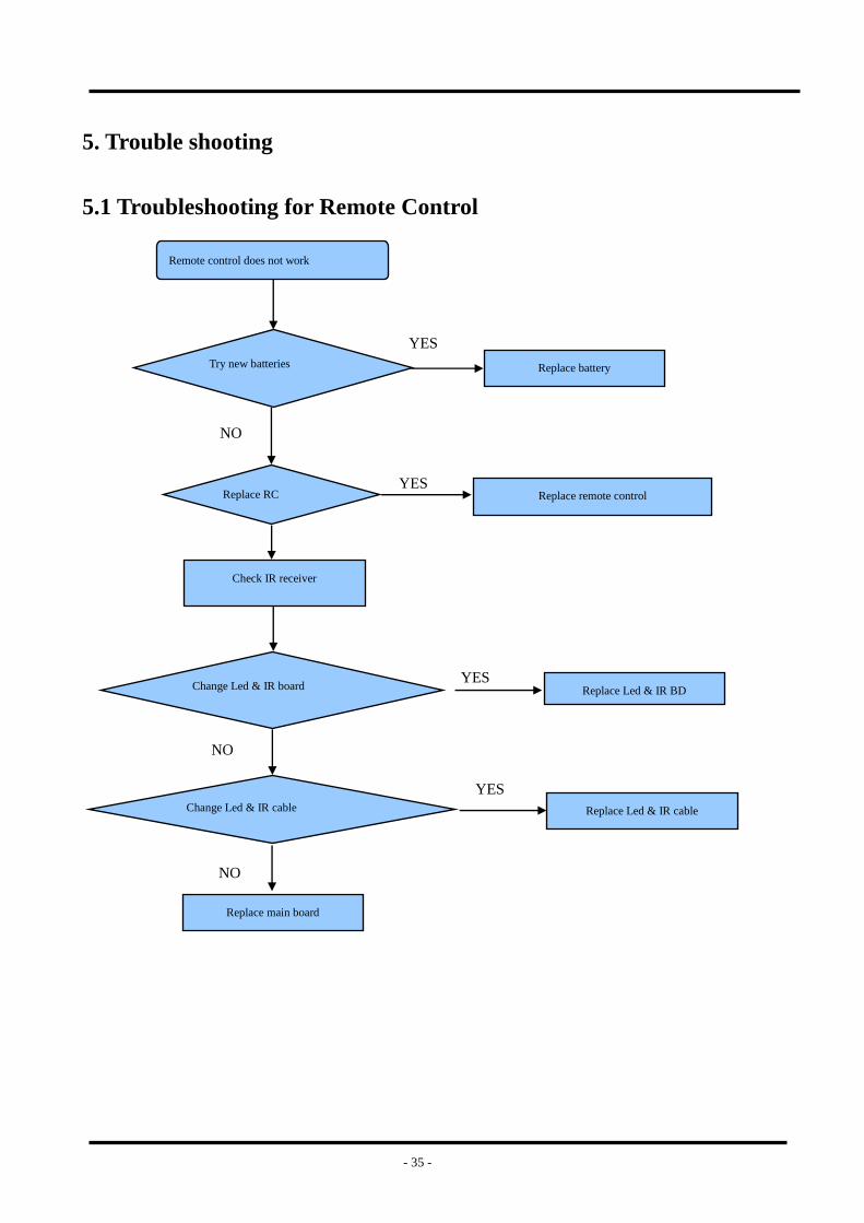
5.1 Troubleshooting for Remote Control
Remote control does not work
Try new batteries
Replace RC
Check IR receiver
Change Led & IR board
Change Led & IR cable
Replace main board
Replace battery
Replace remote control
Replace Led & IR BD
Replace Led & IR cable
YES
YES
NO
YES
NO
YES
NO
- 36 -
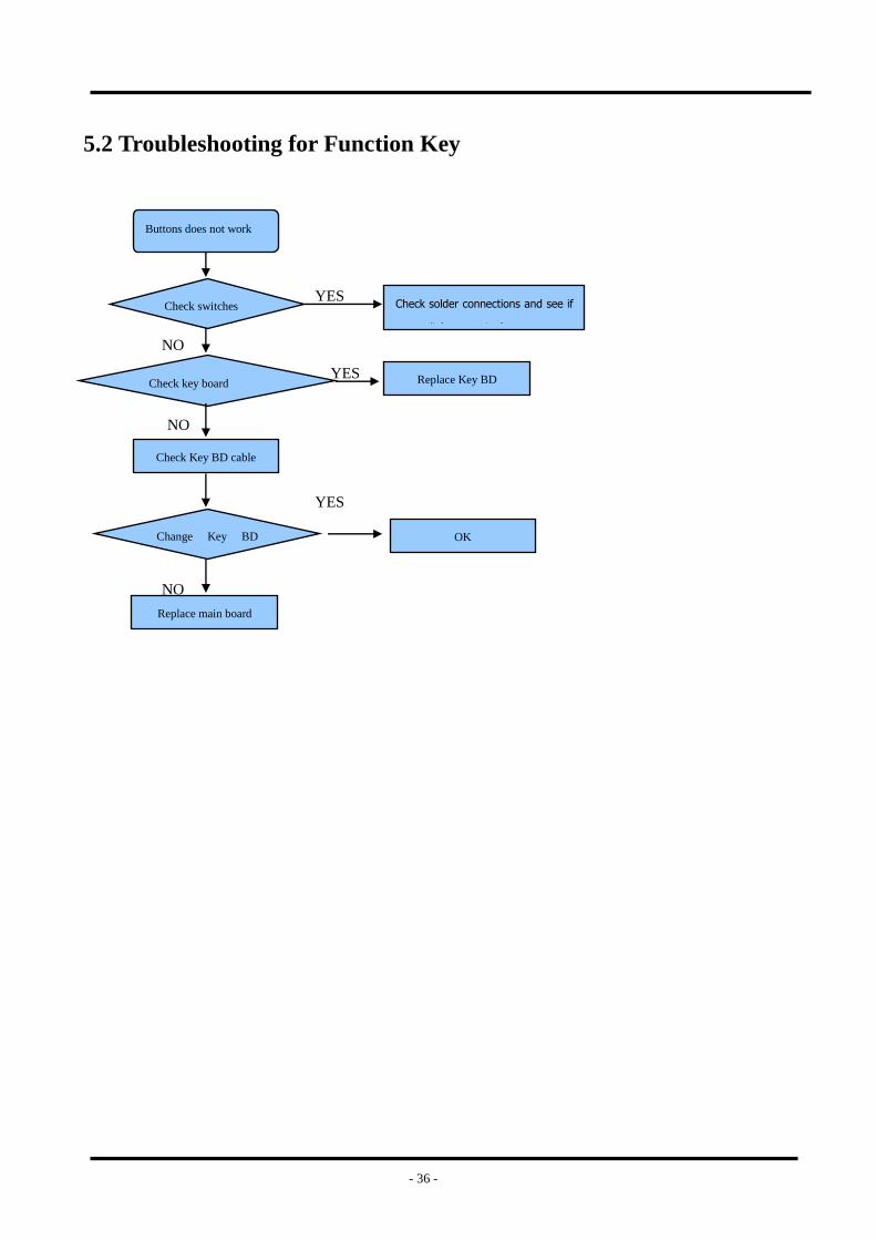
5.2 Troubleshooting for Function Key
Buttons does not work
Check switches
Check key board
Check Key BD cable
Change Key BD
cable
Replace main board
Check solder connections and see if
any switches are stuck.
Replace Key BD
OK
YES
YES
NO
YES
NO
NO
- 37 -
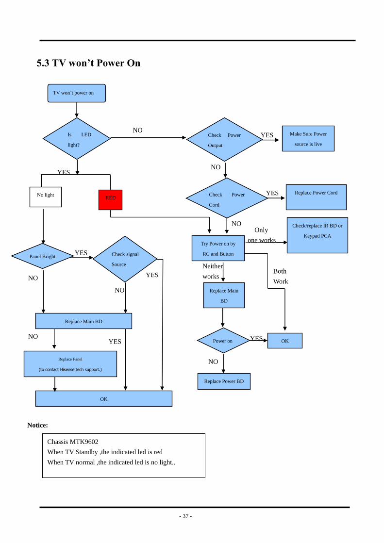
5.3 TV won’t Power On
Notice:
Chassis MTK9602
When TV Standby ,the indicated led is red
When TV normal ,the indicated led is no light..
Make Sure Power
source is live
Replace Power Cord
Check/replace IR BD or
Keypad PCA
TV won’t power on
Is LED
light?
NO
YES
Check Power
Output
YES
NO
Check Power
Cord
Only
one works
Replace Main
BD
Try Power on by
RC and Button
Neither
works Both
Work
Power on OK YES
NO
Replace Power BD
YES
NO
RED No light
NO
Replace Main BD
NO
YES Check signal
Source
YES
NO
YES
Replace Panel
(to contact Hisense tech support.)
OK
Panel Bright
- 38 -
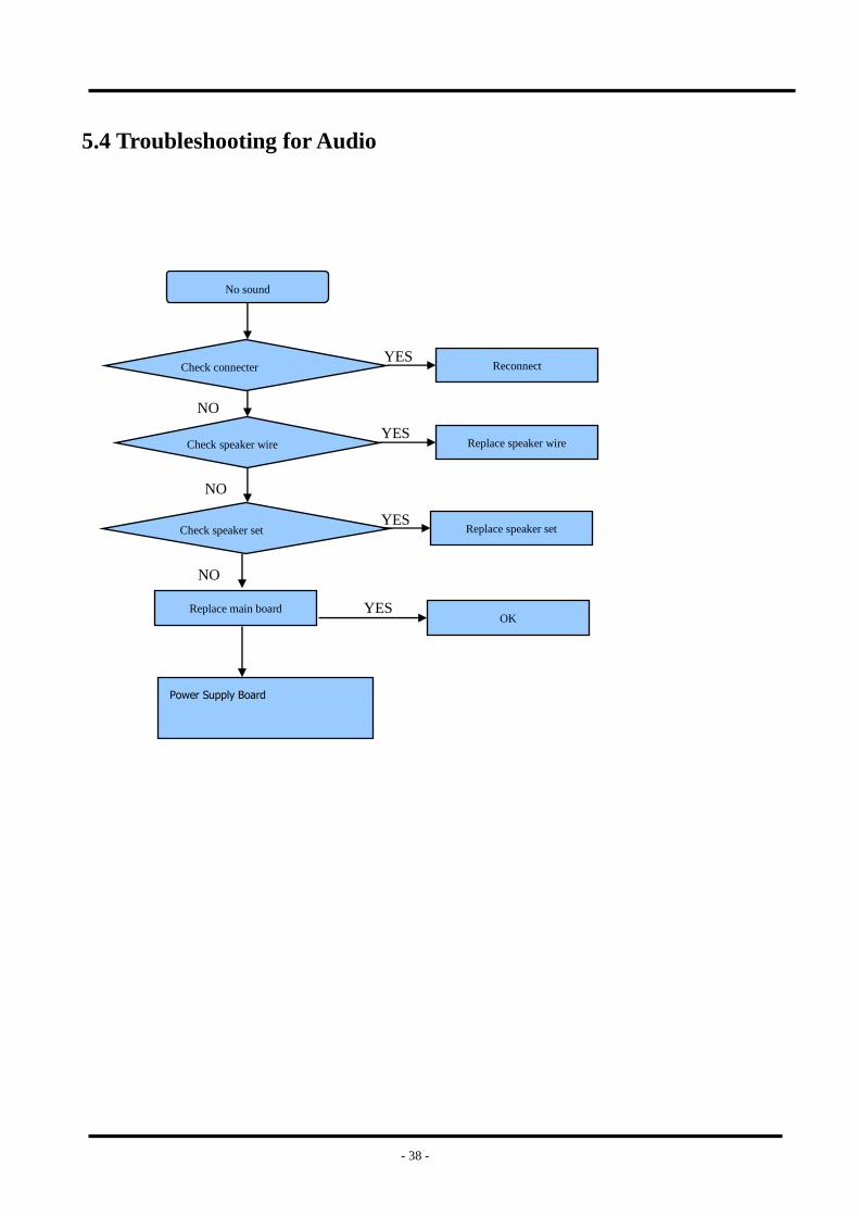
5.4 Troubleshooting for Audio
No sound
Check connecter
Check speaker wire
Replace main board
Reconnect
Replace speaker wire
YES
YES
NO
NO
Check speaker set Replace speaker set YES
NO
OK YES
Power Supply Board
- 39 -
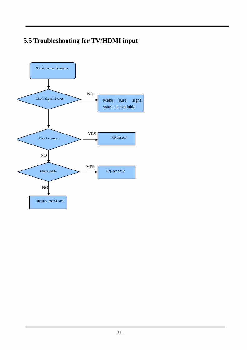
5.5 Troubleshooting for TV/HDMI input
No picture on the screen
Check Signal Source
Check connect
Check cable
Replace main board
Make sure signal
source is available
Reconnect
Replace cable
NO
YES
YES
NO
NO
- 40 -
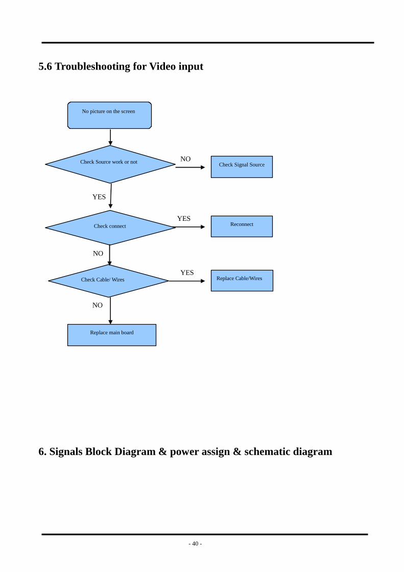
5.6 Troubleshooting for Video input
No picture on the screen
Check Source work or not
Check connect
Check Cable/ Wires
Replace main board
Check Signal Source
Reconnect
Replace Cable/Wires
NO
YES
YES
NO
YES
NO
6. Signals Block Diagram & power assign & schematic diagram
Related Documents