Microcontrollers -Definition, Basics and Trends Anders Pettersson Technical Marketing Manager Microcontrollers Nordic and Baltic

Welcome message from author
This document is posted to help you gain knowledge. Please leave a comment to let me know what you think about it! Share it to your friends and learn new things together.
Transcript
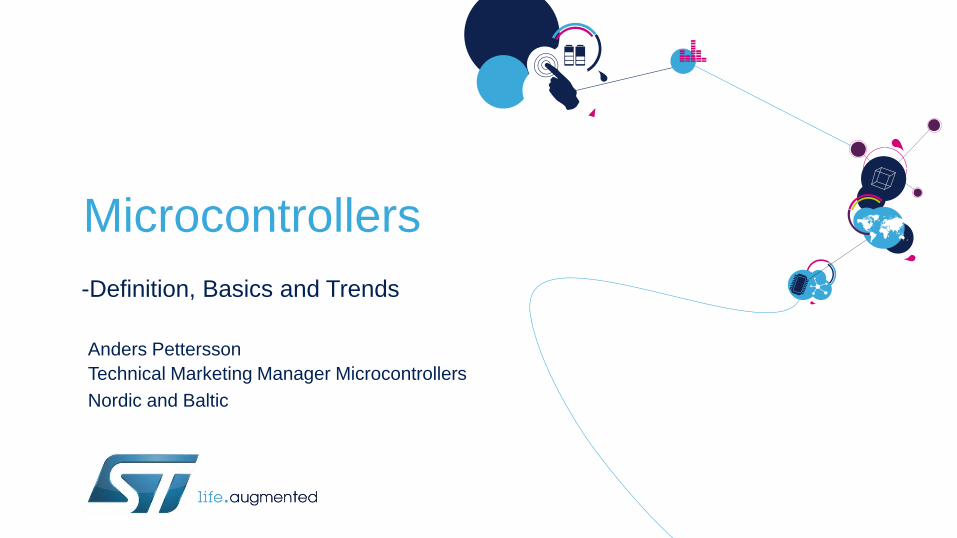
Microcontrollers
-Definition, Basics and Trends
Anders Pettersson
Technical Marketing Manager Microcontrollers
Nordic and Baltic

Agenda 2
13:00 Definition of a Microcontroller Anders Pettersson
Blockdiagram of a generic MCU and Core
Bus system
Architecture
Production Technology
How we think when we design a MCU
Future
14:35 Q & A
Time
Speaker
Presentation
Section
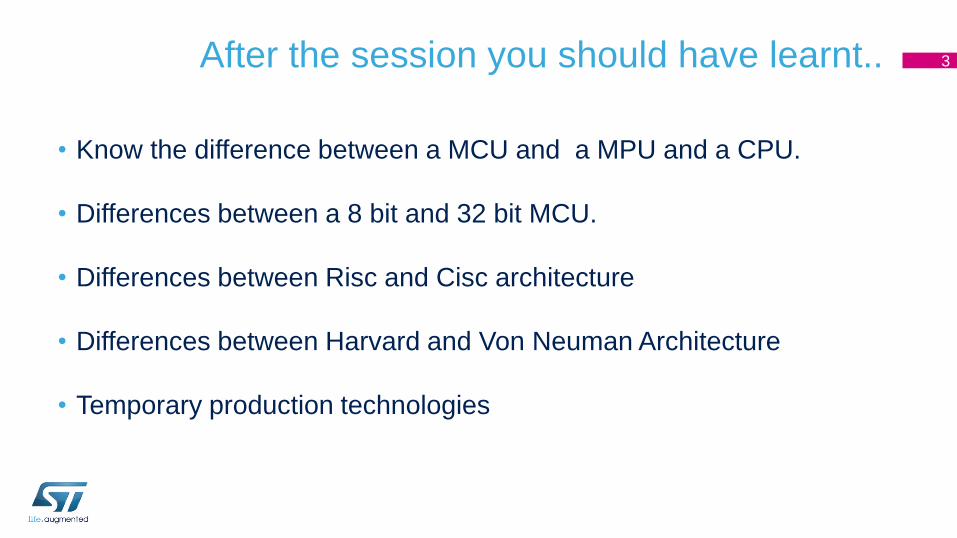
After the session you should have learnt..
• Know the difference between a MCU and a MPU and a CPU.
• Differences between a 8 bit and 32 bit MCU.
• Differences between Risc and Cisc architecture
• Differences between Harvard and Von Neuman Architecture
• Temporary production technologies
3
Definition of a Microcontroller

Definition of a Microcontroller • What is the Definition of a Microcontroller?
• There is no absolut definition...
....from Wikipedia
5

Architecture Cisc and Risc

CISC vs RISC 9
• Emphasis on HW
• Includes Multi-clock complex instructions
• Memory-to-memory: "LOAD" and
"STORE" incorporated in instructions
• Small code sizes, high cycles per second
• Transistors used for storing complex
instructions
CISC
• Emphasis on SW
• Single-clock, reduced instructions only
• Register-to-register: "LOAD" and
"STORE" and independent from
instructions
• Low cycles per second, larger code size
• Spends more transistors on memory
registers
RISC
Example: Multiply (MULT) , considered as a complex instruction
RISC: CISC: MULT 2:3, 5:2 LOAD A, 2:3
LOAD B, 5:2
PROD A, B
STORE 2:3, A

Block diagram and the Core

Essential block diagram of a MCU
CORTEXM3 CPU
72 MHz
6kB-96kB SRAM
AR
M P
erip
he
ral B
us
(max 7
2M
Hz)
2x 12-bit ADC 16 channels / 1Msps
1/2x I2C
1x SPI
1/2/4x USART/LIN Smartcard / IrDA
Modem Control
32/49/80* I/Os
Up to 16 Ext. ITs
Fla
sh I/F
16kB-1MB Flash Memory
Temp Sensor
1x USB 2.0FS
1x bxCAN 2.0B 6x 16-bit PWM Synchronized AC Timer
2x Watchdog (independent & window)
External Memory Interface**
JTAG/SW Debug
XTAL oscillators 32KHz + 4~16MHz
Power Supply Reg 1.8V
POR/PDR/PVD
DMA
3 to 11 Channels
Nested vect IT Ctrl
2x SPI/I2S**
2x DAC**
1x SDIO**
1x USART/LIN Smartcard/IrDA Modem-Ctrl
1x SPI
Bridge
Bridge
1x SysTick Timer
AR
M L
ite
Hi-S
pe
ed
Bu
s
Ma
trix
/ A
rbite
r (m
ax 7
2M
Hz)
Int. RC oscillators 32KHz + 8MHz
PLL
Clock Control RTC / AWU
ARM Peripheral Bus
(max 36MHz)
20B Backup Regs
2/3/5x 16-bit Timer
Clocks
CPU
RAM
ROM (FLASH)
Peripherals
11
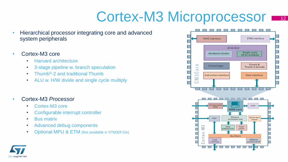
Cortex-M3 Microprocessor 12
• Hierarchical processor integrating core and advanced system peripherals
• Cortex-M3 core
• Harvard architecture
• 3-stage pipeline w. branch speculation
• Thumb®-2 and traditional Thumb
• ALU w. H/W divide and single cycle multiply
• Cortex-M3 Processor
• Cortex-M3 core
• Configurable interrupt controller
• Bus matrix
• Advanced debug components
• Optional MPU & ETM (Not available in STM32F10x)
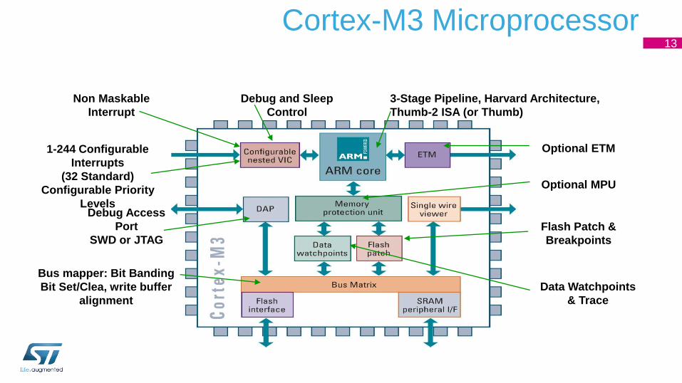
Cortex-M3 Microprocessor
Debug Access
Port
SWD or JTAG
Flash Patch &
Breakpoints
Data Watchpoints
& Trace
Debug and Sleep
Control
3-Stage Pipeline, Harvard Architecture,
Thumb-2 ISA (or Thumb)
1-244 Configurable
Interrupts
(32 Standard)
Configurable Priority
Levels
Non Maskable
Interrupt
Optional ETM
Optional MPU
Bus mapper: Bit Banding
Bit Set/Clea, write buffer
alignment
13
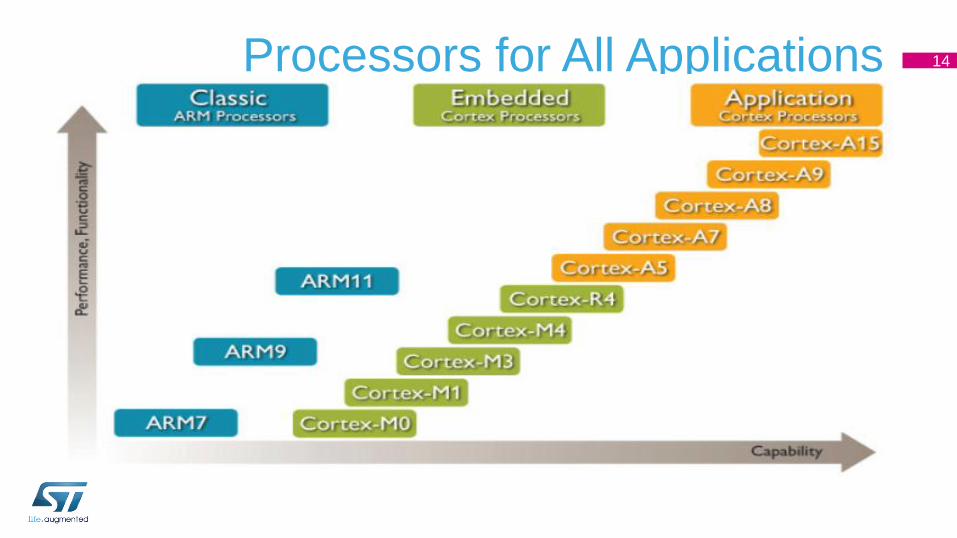
Processors for All Applications 14
Bus system
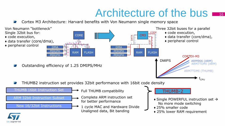
Architecture of the bus
THUMB-2 THUMB 16bit Instruction Set
ARM 32bit Instruction Subset
New 16/32bit Instructions
Full THUMB compatibility
1 cycle MAC and Hardware Divide Unaligned data, Bit banding
♦ Single POWERFUL instruction set
No more mode switching ♦ 25% smaller code ♦ 25% lower RAM requirement
Complete ARM instruction set for better performance
THUMB2 instruction set provides 32bit performance with 16bit code density
CORTEX-M3
ARM7TDMI (ARM)
ARM7TDMI (THUMB)
fCPU
DMIPS ARM966 (ARM)
Outstanding efficiency of 1.25 DMIPS/MHz
Cortex M3 Architecture: Harvard benefits with Von Neumann single memory space
Von Neumann “bottleneck” Single 32bit bus for: ♦ code execution,
♦ data transfer (core/dma), ♦ peripheral control
Three 32bit buses for a parallel ♦ code execution, ♦ data transfer (core/dma), ♦ peripheral control
0
0 0 0
0 1 1 1 1 1
1
0 1 0 1
1 1
1
1
1
1 0
0 0
0
0 0
0
0 1 1 1
1
0 1
1
0 0 0
0
0
0
0 0 0
0 0 1
0 1 1
1
1 1
CORE
FLASH RAM
DMA
PERIPH
PERIPH
CODE
1
1 1
0
1 0 0
0
CM3
FLASH RAM
DMA
PERIPH
PERIPH
1 0
1
1 0
1
CST
0
0
0 0
1
0
1
1
0 1
1
0
DATA
16
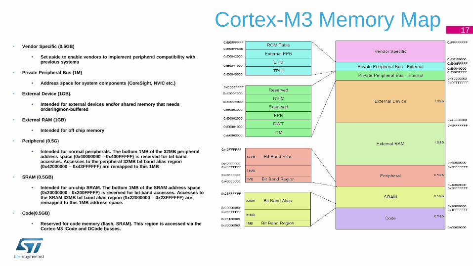
Cortex-M3 Memory Map • Vendor Specific (0.5GB)
• Set aside to enable vendors to implement peripheral compatibility with previous systems
• Private Peripheral Bus (1M)
• Address space for system components (CoreSight, NVIC etc.)
• External Device (1GB).
• Intended for external devices and/or shared memory that needs ordering/non-buffered
• External RAM (1GB)
• Intended for off chip memory
• Peripheral (0.5G)
• Intended for normal peripherals. The bottom 1MB of the 32MB peripheral address space (0x40000000 – 0x400FFFFF) is reserved for bit-band accesses. Accesses to the peripheral 32MB bit band alias region (0x42000000 – 0x43FFFFFF) are remapped to this 1MB
• SRAM (0.5GB)
• Intended for on-chip SRAM. The bottom 1MB of the SRAM address space (0x20000000 - 0x200FFFFF) is reserved for bit-band accesses. Accesses to the SRAM 32MB bit band alias region (0x22000000 – 0x23FFFFFF) are remapped to this 1MB address space.
• Code(0.5GB)
• Reserved for code memory (flash, SRAM). This region is accessed via the Cortex-M3 ICode and DCode busses.
17
Production Technologies • The road to success...
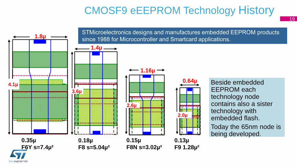
CMOSF9 eEEPROM Technology History
0.13µ
F9 1.28µ²
0.64µ
2.0µ
0.15µ
F8N s=3.02µ²
1.16µ
2.6µ
0.18µ
F8 s=5.04µ²
1.4µ
3.6µ
0.35µ
F6Y s=7.4µ²
1.8µ
4.1µ
STMicroelectronics designs and manufactures embedded EEPROM products
since 1988 for Microcontroller and Smartcard applications.
Beside embedded EEPROM each technology node contains also a sister technology with embedded flash.
Today the 65nm node is being developed.
19
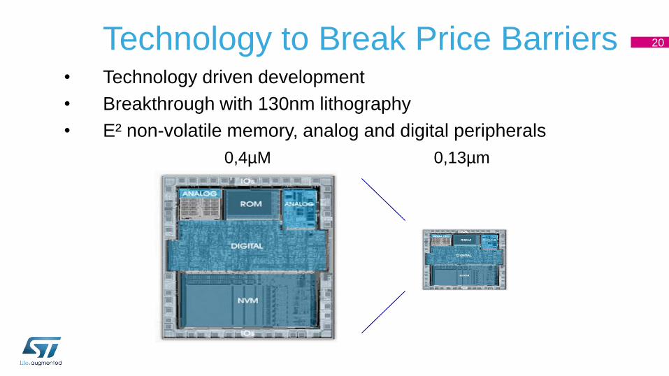
Technology to Break Price Barriers
0.45µm 0.13µm0.45µm 0.13µm
• Technology driven development
• Breakthrough with 130nm lithography
• E² non-volatile memory, analog and digital peripherals
0,4µM 0,13µm
20
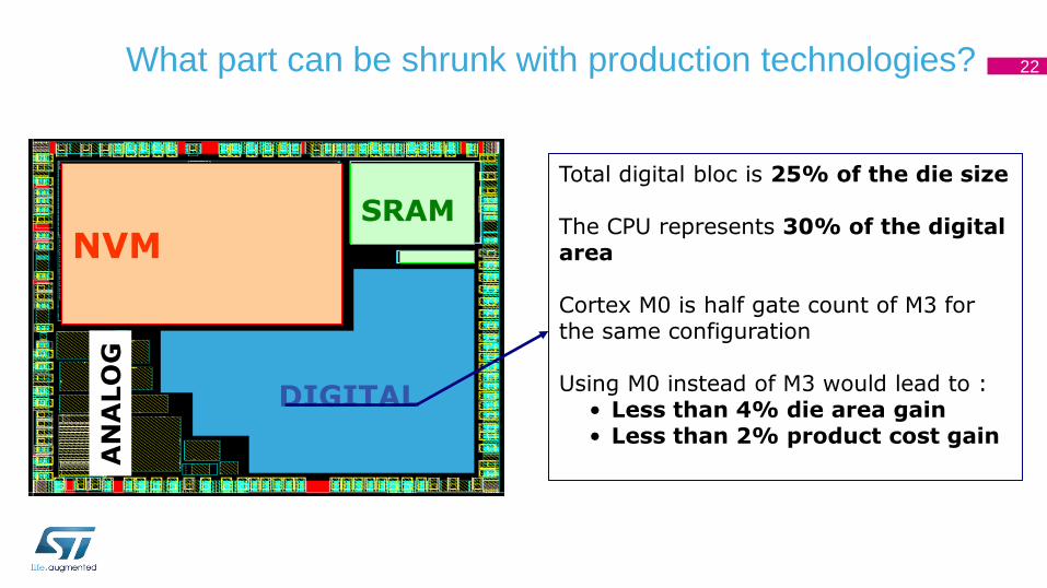
What part can be shrunk with production technologies?
NVM SRAM
DIGITAL
AN
ALO
G
Total digital bloc is 25% of the die size The CPU represents 30% of the digital area Cortex M0 is half gate count of M3 for the same configuration Using M0 instead of M3 would lead to :
• Less than 4% die area gain • Less than 2% product cost gain
22

Example of Cost Distribution for a MCU Typical cost structure
Cost share
SiliconTestPackagingLogistic/StockRoyalties
• Majority of the cost is not coming from the silicon itself
• The smaller the die size, the higher the non silicon cost
• Focusing all the innovation in the silicon is not the only way to decrease the
cost
24
How do we think when we design a MCU?
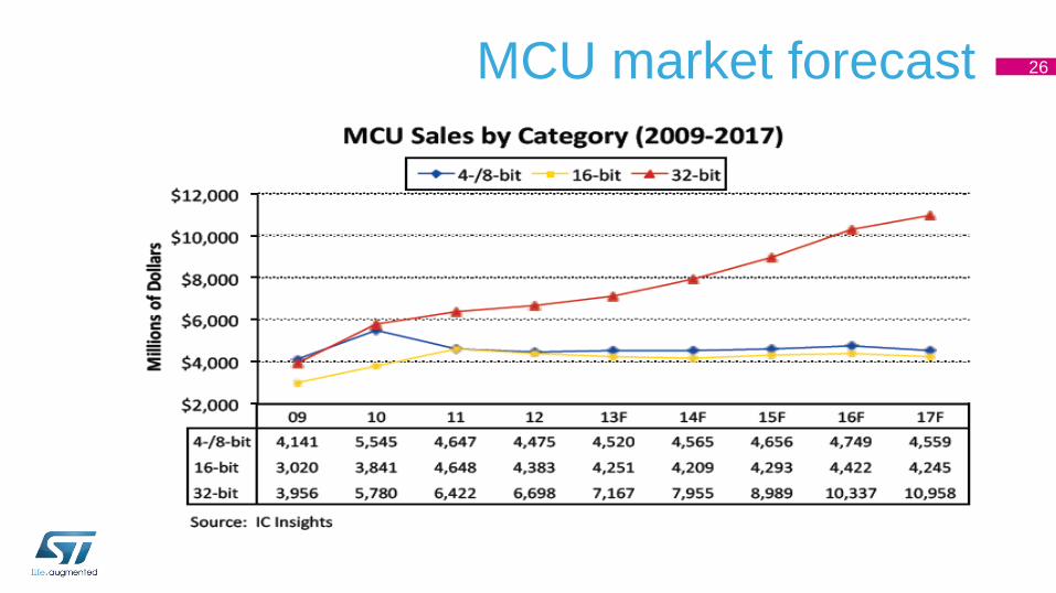
MCU market forecast 26
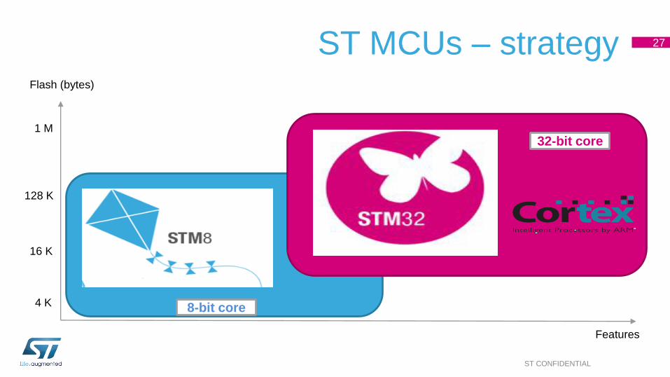
ST MCUs – strategy
ST CONFIDENTIAL
32-bit ARM Cortex™-M
Features
4 K
16 K
128 K
1 M
8-bit core
32-bit core
Flash (bytes)
27
29
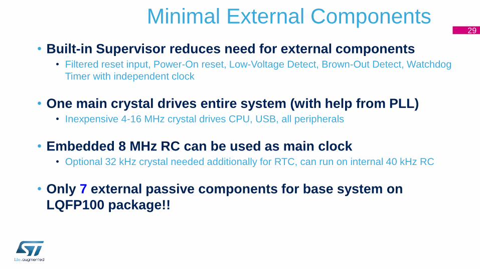
• Built-in Supervisor reduces need for external components • Filtered reset input, Power-On reset, Low-Voltage Detect, Brown-Out Detect, Watchdog
Timer with independent clock
• One main crystal drives entire system (with help from PLL) • Inexpensive 4-16 MHz crystal drives CPU, USB, all peripherals
• Embedded 8 MHz RC can be used as main clock • Optional 32 kHz crystal needed additionally for RTC, can run on internal 40 kHz RC
• Only 7 external passive components for base system on
LQFP100 package!!
Minimal External Components

ST has licensed all Cortex-M processors 30
Binary and tool compatible
MCU
• Forget traditional 8/16/32-bit classifications and get
• Seamless architecture across all applications
• Every product optimized for ultra-low power and ease of use
Cortex-M0 Cortex-M3 Cortex-M4 8/16-bit applications 16/32-bit applications 32-bit/DSC applications
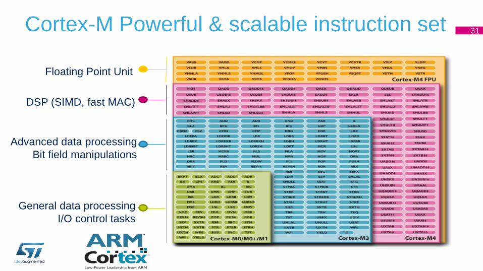
Cortex-M Powerful & scalable instruction set 31
Floating Point Unit
DSP (SIMD, fast MAC)
Advanced data processing
Bit field manipulations
General data processing
I/O control tasks

STM32 – 7 product series 32
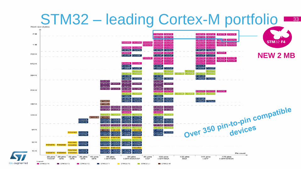
STM32 – leading Cortex-M portfolio 33
NEW 2 MB

3x 12-bit ADC 24 channels / 2Msps
3x I2C
Up to 16 Ext. ITs
Temp Sensor
2x6x 16-bit PWM Synchronized AC Timer
2x Watchdog (independent & window)
5x 16-bit Timer
XTAL oscillators 32KHz + 8~25MHz
Power Supply Reg 1.2V
POR/PDR/PVD
2x DAC + 2 Timers
2 x USART/LIN
1 x SPI
1 x Systic Timer
PLL Clock Control
RTC / AWU
4KB backup RAM
Ethernet MAC 10/100,
IEEE1588
USB 2.0 OTG FS
4x USART/LIN
1x SDIO
Int. RC oscillators 32KHz + 16MHz
3 x 16bit Timer
2x 32-bit Timer
2x CAN 2.0B
2 x SPI / I2S
HS requires an external PHY connected to ULPI interface,
** Encryption is only available on STM32F415 and STM32F417
51/82/114/140 I/Os
USB 2.0 OTG FS/HS
Encryption**
Camera Interface
STM32F4xx Block Diagram Cortex-M4 w/ FPU, MPU and ETM
Memory
Up to 1MB Flash memory
192KB RAM including 64KB CCM data RAM
FSMC up to 60MHz New application specific peripherals
USB OTG HS w/ ULPI interface
Camera interface
HW Encryption**: DES, 3DES, AES 256-bit, SHA-1
hash, RNG. Enhanced peripherals
USB OTG Full speed
ADC: 0.416µs conversion/2.4Msps, up to
7.2Msps in interleaved triple mode
ADC/DAC working down to 1.8V
Dedicated PLL for I2S precision
Ethernet w/ HW IEEE1588 v2.0
32-bit RTC with calendar
4KB backup SRAM in VBAT domain
Pure 1% RC
2 x 32bit and 8 x 16bit Timers
high speed USART up to 10.5Mb/s
high speed SPI up to 37.5Mb/s
RDP (JTAG fuse)
More I/O:s in UFBGA 176 package
Fla
sh I/F
AR
M ®
32-b
it m
ulti-
AH
B b
us m
atr
ix
Arb
iter
(ma
x 1
50
MH
z)
CORTEX-M4 CPU + FPU + MPU
168 MHz
128KB SRAM
JTAG/SW Debug
DMA
16 Channels
Nested vect IT Ctrl
Bridge
Bridge APB1 (max 42MHz)
ETM
512kB- 1MB Flash Memory
External Memory Interface
AHB1
(max 168MHz)
AHB2 (max 168MHz)
AP
B2 (
ma
x 8
4M
Hz)
64KB CCM data RAM
D-bus
I-bus
S-bus
34
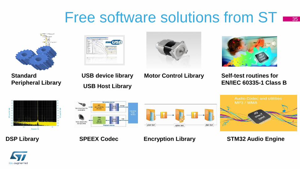
Free software solutions from ST
USB device library
USB Host Library
DSP Library SPEEX Codec
Motor Control Library Standard
Peripheral Library
Encryption Library
Self-test routines for
EN/IEC 60335-1 Class B
STM32 Audio Engine
35
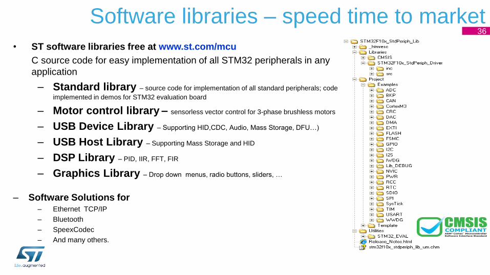
Software libraries – speed time to market
• ST software libraries free at www.st.com/mcu
C source code for easy implementation of all STM32 peripherals in any
application
– Standard library – source code for implementation of all standard peripherals; code
implemented in demos for STM32 evaluation board
– Motor control library – sensorless vector control for 3-phase brushless motors
– USB Device Library – Supporting HID,CDC, Audio, Mass Storage, DFU…)
– USB Host Library – Supporting Mass Storage and HID
– DSP Library – PID, IIR, FFT, FIR
– Graphics Library – Drop down menus, radio buttons, sliders, …
– Software Solutions for – Ethernet TCP/IP
– Bluetooth
– SpeexCodec
– And many others.
36
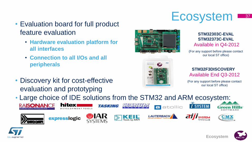
37 Ecosystem
STM32F3DISCOVERY
Available End Q3-2012
(For any support before please contact
our local ST office)
STM32303C-EVAL
STM32373C-EVAL
Available in Q4-2012
(For any support before please contact
our local ST office)
• Evaluation board for full product
feature evaluation
• Hardware evaluation platform for
all interfaces
• Connection to all I/Os and all
peripherals
• Discovery kit for cost-effective
evaluation and prototyping
• Large choice of IDE solutions from the STM32 and ARM ecosystem:
Ecosystem
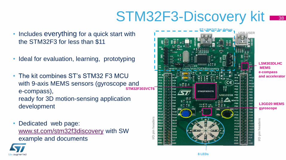
STM32F3-Discovery kit 38
STM32F303VCT6
8 LEDs
USB USER ST-LINK/V2 for debug
STM32F303VCT6
I/O
pin
he
ad
ers
I/O
pin
he
ad
ers
L3GD20 MEMS
gyroscope
LSM303DLHC
MEMS
e-compass
and accelerator
• Includes everything for a quick start with
the STM32F3 for less than $11
• Ideal for evaluation, learning, prototyping
• The kit combines ST’s STM32 F3 MCU
with 9-axis MEMS sensors (gyroscope and
e-compass),
ready for 3D motion-sensing application
development
• Dedicated web page:
www.st.com/stm32f3discovery with SW
example and documents

Future
MCU Trends – a selection of topics • Price → Technology
• Performance → Low Power and MIPS
• Memory size → Larger flash and RAM
• Peripheral Integration → analog, RF
• Industry standard cores → Cortex Mx
• Advanced Peripherals → USB Ethernet LCD SDRAM
• Predefined Libraries + RTOS → Abstraction from the hardware
42
Q & A

After the session you should have learnt..
• Know the difference between a MCU and a MPU and a CPU.
• Differences between a 8 bit and 32 bit MCU.
• Differences between Risc and Cisc architecture
• Differences between Harvard and Von Neuman Architecture
• Temporary production technologies
46
Thank you
www.st.com/stm32
47
Related Documents