Liquid Propulsion Systems – Evolution & Advancements Launch Vehicle Propulsion & Systems Rick Ballard Liquid Engine Systems Lead SLS Liquid Engines Office NASA / MSFC All rights reserved. No part of this publication may be reproduced, distributed, or transmitted, unless for course participation and to a paid course student, in any form or by any means, or stored in a database or retrieval system, without the prior written permission of AIAA and/or course instructor. Contact the American Institute of Aeronautics and Astronautics, Professional Development Program, Suite 500, 1801 Alexander Bell Drive, Reston, VA 20191-4344 LPTC Liquid Propulsion Technical Committee https://ntrs.nasa.gov/search.jsp?R=20140002716 2018-06-12T11:28:29+00:00Z

Welcome message from author
This document is posted to help you gain knowledge. Please leave a comment to let me know what you think about it! Share it to your friends and learn new things together.
Transcript

Liquid Propulsion Systems –
Evolution & Advancements
Launch Vehicle Propulsion &
Systems
Rick Ballard
Liquid Engine Systems Lead
SLS Liquid Engines Office
NASA / MSFC
All rights reserved. No part of this publication may be reproduced, distributed, or transmitted, unless for course participation and to a paid course student, in
any form or by any means, or stored in a database or retrieval system, without the prior written permission of AIAA and/or course instructor. Contact the
American Institute of Aeronautics and Astronautics, Professional Development Program, Suite 500, 1801 Alexander Bell Drive, Reston, VA 20191-4344
LPTC Liquid Propulsion
Technical Committee
https://ntrs.nasa.gov/search.jsp?R=20140002716 2018-06-12T11:28:29+00:00Z
Modules
1. Rocket Propulsion Fundamentals 2. LRE Applications 3. Liquid Propellants 4. Engine Power Cycles 5. Engine Components
TOPICS
• Thrust
• Specific Impulse
• Mixture Ratio
• Isp vs. MR
• Density vs. Isp
• Propellant Mass vs. Volume
• Area Ratio
Module 1:
Rocket Propulsion
Fundamentals
Warning: Contents deal with math,
physics and thermodynamics.
Be afraid…be very afraid…
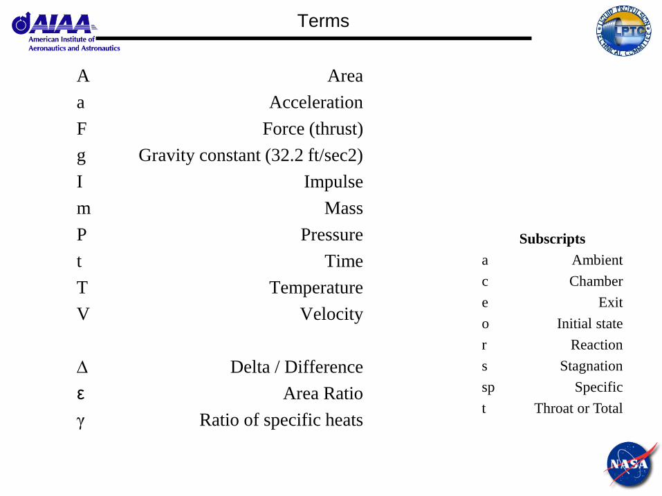
Terms
A Area
a Acceleration
F Force (thrust)
g Gravity constant (32.2 ft/sec2)
I Impulse
m Mass
P Pressure
t Time
T Temperature
V Velocity
∆ Delta / Difference
ε Area Ratio
γ Ratio of specific heats
Subscripts
a Ambient
c Chamber
e Exit
o Initial state
r Reaction
s Stagnation
sp Specific
t Throat or Total

Thrust (1/3)
Rocket thrust can be explained using Newton’s 2nd and 3rd laws of motion.
2nd Law: a force applied to a body is equal to the mass of the body and its
acceleration in the direction of the force.
3rd Law: For every action, there is an equal and opposite reaction.
In rocket propulsion, a mass of propellant (m) is accelerated (via the
combustion process) from initial velocity (Vo) to an exit velocity (Ve). The
acceleration of this mass is written as:
maF
ra FF
tVVa oe /
Thrust (2/3)
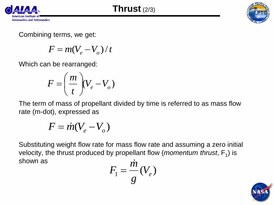
Combining terms, we get:
Which can be rearranged:
The term of mass of propellant divided by time is referred to as mass flow
rate (m-dot), expressed as
Substituting weight flow rate for mass flow rate and assuming a zero initial
velocity, the thrust produced by propellant flow (momentum thrust, F1) is
shown as
tVVmF oe /)(
)( oe VVt
mF
)( oe VVmF
)(1 eVg
mF
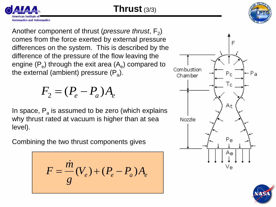
Thrust (3/3)
Another component of thrust (pressure thrust, F2)
comes from the force exerted by external pressure
differences on the system. This is described by the
difference of the pressure of the flow leaving the
engine (Pe) through the exit area (Ae) compared to
the external (ambient) pressure (Pa).
In space, Pa is assumed to be zero (which explains
why thrust rated at vacuum is higher than at sea
level).
Combining the two thrust components gives
eae APPF )(2
eaee APPVg
mF )()(

Specific Impulse (1/4)
The total impulse (It) is the thrust integrated over
the run duration (time, t)
Assuming constant thrust and negligible transients
(i.e., start and shutdown), this becomes
The specific impulse, (Isp) is the total impulse
generated per weight of propellant
dtFI
t
t 0
FtIt
m
F
dtmg
dtF
It
o
t
sp
0
0
This is really what you need to know about Isp.
If you want to learn some more, stay seated.
The rest of you can go get some coffee for
about 10 minutes…
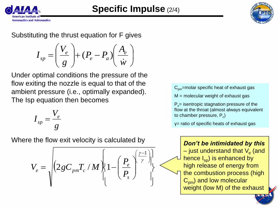
Specific Impulse (2/4)
Substituting the thrust equation for F gives
Under optimal conditions the pressure of the
flow exiting the nozzle is equal to that of the
ambient pressure (i.e., optimally expanded).
The Isp equation then becomes
Where the flow exit velocity is calculated by
w
APP
g
VI e
aee
sp )(
g
VI e
sp
1
1/2s
ecpme
P
PMTgCV
Cpm=molar specific heat of exhaust gas
M = molecular weight of exhaust gas
Ps= isentropic stagnation pressure of the
flow at the throat (almost always equivalent
to chamber pressure, Pc)
γ= ratio of specific heats of exhaust gas
Don’t be intimidated by this
– just understand that Ve (and
hence Isp) is enhanced by
high release of energy from
the combustion process (high
Cpm) and low molecular
weight (low M) of the exhaust
By definition
and
Where R is the universal
gas constant, then
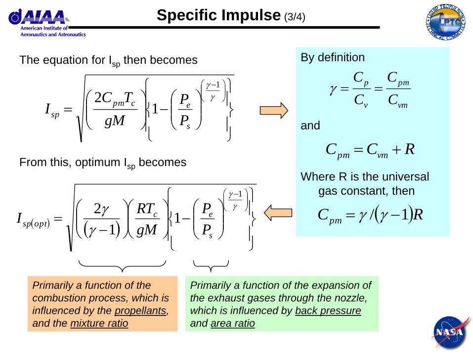
Specific Impulse (3/4)
The equation for Isp then becomes
From this, optimum Isp becomes
vm
pm
v
p
C
C
C
C
1
12
s
ecpm
spP
P
gM
TCI
RCC vmpm
RCpm 1/
1
11
2
s
ecoptsp
P
P
gM
RTI
Primarily a function of the
combustion process, which is
influenced by the propellants,
and the mixture ratio
Primarily a function of the expansion of
the exhaust gases through the nozzle,
which is influenced by back pressure
and area ratio
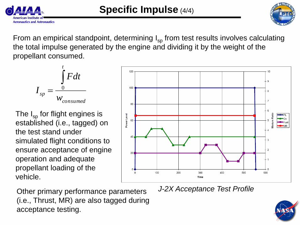
Specific Impulse (4/4)
From an empirical standpoint, determining Isp from test results involves calculating
the total impulse generated by the engine and dividing it by the weight of the
propellant consumed.
consumed
t
spw
dtF
I
0
The Isp for flight engines is
established (i.e., tagged) on
the test stand under
simulated flight conditions to
ensure acceptance of engine
operation and adequate
propellant loading of the
vehicle.
J-2X Acceptance Test Profile Other primary performance parameters
(i.e., Thrust, MR) are also tagged during
acceptance testing.
Mixture Ratio
f
o
w
wMR
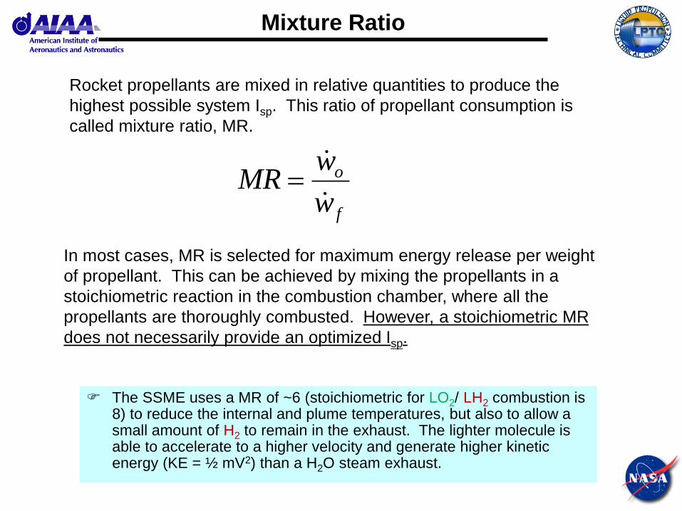
Rocket propellants are mixed in relative quantities to produce the
highest possible system Isp. This ratio of propellant consumption is
called mixture ratio, MR.
In most cases, MR is selected for maximum energy release per weight
of propellant. This can be achieved by mixing the propellants in a
stoichiometric reaction in the combustion chamber, where all the
propellants are thoroughly combusted. However, a stoichiometric MR
does not necessarily provide an optimized Isp.
The SSME uses a MR of ~6 (stoichiometric for LO2/ LH2 combustion is 8) to reduce the internal and plume temperatures, but also to allow a small amount of H2 to remain in the exhaust. The lighter molecule is able to accelerate to a higher velocity and generate higher kinetic energy (KE = ½ mV2) than a H2O steam exhaust.

Vacu
um
Isp
(sec)
1 2 3 4 5 6 7 8 9 10
480
460
440
420
400
380
Mixture Ratio
W inPlot v4.54
VACIDEAL VACIREAL
• “Ideal” for SSME-like fluid conditions (for LO2/LH2 combustion) and nozzle having ε = 77 used with CEA FORTRAN code.
• “Real” obtained by accounting for typical LO2/LH2 combustion/nozzle efficiencies.
Isp vs. MR
Sto
ich
iom
etri
c LO
2/LH2
SSM
E
J-2
X

Density vs. Isp
Liquid bipropellant combinations offer a wide
range of performance capabilities.
Each combination has multiple factors that
should be weighed when selecting one for a
vehicle. • Performance (Isp)
• Density (higher is better)
• Storability (venting?)
• Ground Ops (hazards?)
• Etc.
One of the more critical trades is that of
performance versus density.
LO2/LH2 offers the highest Isp performance,
but at the cost of poor density (thus increasing
tank size).
Trading Isp versus density is sometimes
referred to as comparing “bulk impulse” or
“density impulse”.
Density
(g/ml)
Density
(lb/ft3)
Hydrogen 0.07 4.4
Methane 0.42 26.4
RP-1 0.81 50.6
Oxygen 1.14 71.2
As an example, the densities
and Isp performance of the
following propellant
combinations will be
compared.
Pc = 300 psia
expanded to
14.7 psia
MR
(O/F)
Isp
(sec)
LO2/LH2 3.5 347(1)
LO2/CH4 2.33 263(2)
LO2/RP-1 2.4 263(2)
(1) SC (2) FC
0
500000
1000000
1500000
2000000
2500000
3000000
3500000
1 2 3
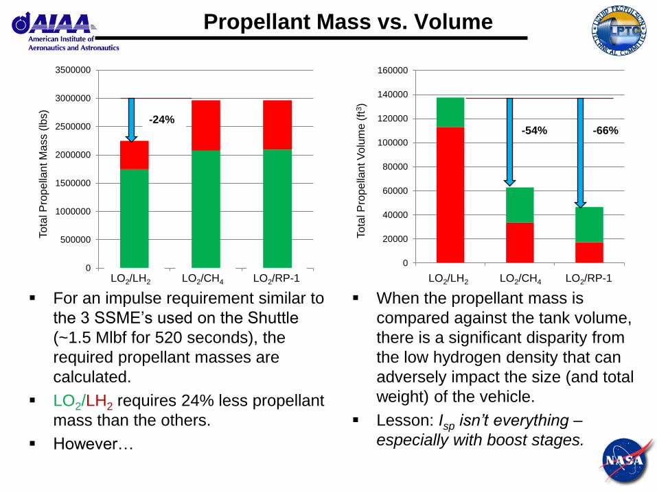
Propellant Mass vs. Volume
For an impulse requirement similar to
the 3 SSME’s used on the Shuttle
(~1.5 Mlbf for 520 seconds), the
required propellant masses are
calculated.
LO2/LH2 requires 24% less propellant
mass than the others.
However…
When the propellant mass is
compared against the tank volume,
there is a significant disparity from
the low hydrogen density that can
adversely impact the size (and total
weight) of the vehicle.
Lesson: Isp isn’t everything –
especially with boost stages.
0
20000
40000
60000
80000
100000
120000
140000
160000
1 2 3LO2/LH2 LO2/CH4 LO2/LH2 LO2/CH4 LO2/RP-1 LO2/RP-1
To
tal P
rop
ella
nt M
ass (
lbs)
To
tal P
rop
ella
nt V
olu
me (
ft3)
-24% -54% -66%
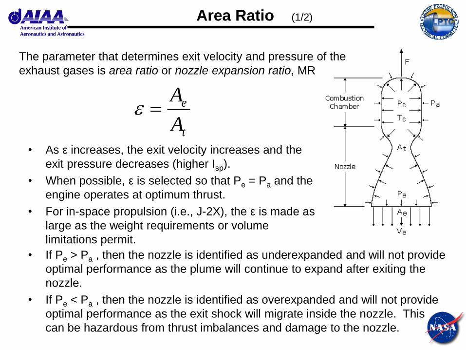
Area Ratio (1/2)
The parameter that determines exit velocity and pressure of the
exhaust gases is area ratio or nozzle expansion ratio, MR
t
e
A
A
• As ε increases, the exit velocity increases and the
exit pressure decreases (higher Isp).
• When possible, ε is selected so that Pe = Pa and the
engine operates at optimum thrust.
• For in-space propulsion (i.e., J-2X), the ε is made as
large as the weight requirements or volume
limitations permit.
• If Pe > Pa , then the nozzle is identified as underexpanded and will not provide
optimal performance as the plume will continue to expand after exiting the
nozzle.
• If Pe < Pa , then the nozzle is identified as overexpanded and will not provide
optimal performance as the exit shock will migrate inside the nozzle. This
can be hazardous from thrust imbalances and damage to the nozzle.
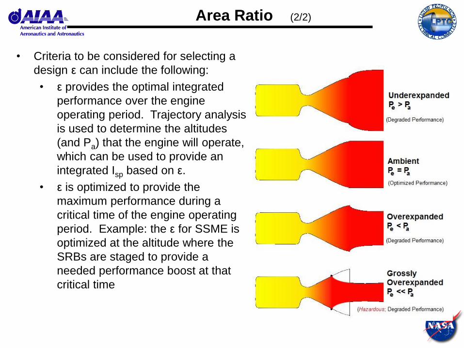
Area Ratio (2/2)
• Criteria to be considered for selecting a
design ε can include the following:
• ε provides the optimal integrated
performance over the engine
operating period. Trajectory analysis
is used to determine the altitudes
(and Pa) that the engine will operate,
which can be used to provide an
integrated Isp based on ε.
• ε is optimized to provide the
maximum performance during a
critical time of the engine operating
period. Example: the ε for SSME is
optimized at the altitude where the
SRBs are staged to provide a
needed performance boost at that
critical time
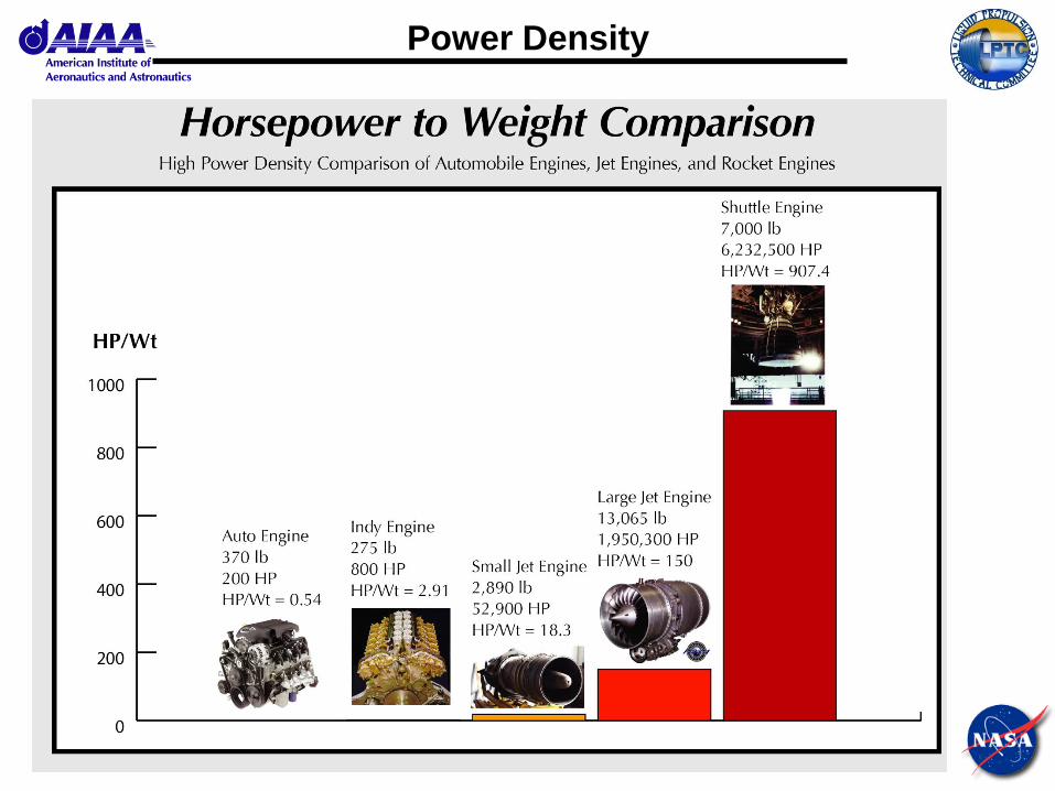
Power Density
2.1
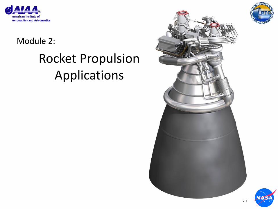
Module 2:
Rocket Propulsion Applications

2.2
Rocket Propulsion Applications

2.3
107
106
105
104
103
102 10-5 10-4 10-3 10-2 10-1 1 10 102
SAILS D
eep
Sp
ace
Omniplanetary
Lau
nch
SPECULATIVE MOTIVE PHYSICS
ANTIMATTER
CONTINUOUS
FUSION
PULSED FUSION
PULSED FISSION
NON- CHEM RBCC
THERMAL FISSION LASER/SOLAR
THERMAL ROCKETS
ELECTRO-
MAGNETIC
ROCKETS
ELECTRO-
THERMAL
ROCKETS
ELECTRO-
STATIC
ROCKETS
CHEMICAL RBCC
CHEMICAL
ROCKETS
Expand the Frontier
(>2023)
Develop the Frontier
(2010 - 2023)
Spec
ific
Imp
uls
e (s
ecs)
Vehicle Acceleration or T/W Ratio (g’s)
Unproven Technology (TRL 1-3) Demonstrated Technology (TRL 4-6) Operational Systems (TRL 7-9)
In-Space Propulsion Performance
2.4
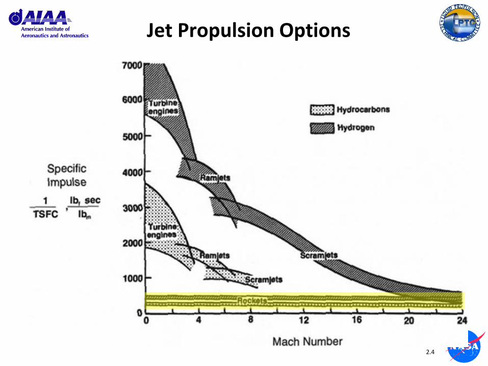
Jet Propulsion Options
2.5
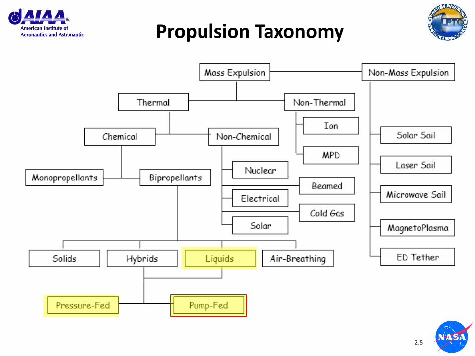
Propulsion Taxonomy
2.6
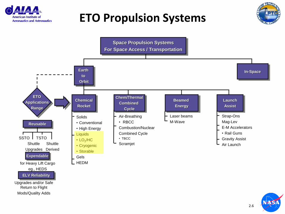
ETO Propulsion Systems
Space Propulsion Systems
For Space Access / Transportation
Earth
to
Orbit
In-Space
Chemical
Rocket
Chem/Thermal
Combined
Cycle
Launch
Assist
Beamed
Energy
ETO
Applications
Range
Expendable
ELV Reliability
Reusable
SSTO TSTO
Shuttle Shuttle
Upgrades Derived
for Heavy Lift Cargo
eg., HEDS
Upgrades and/or Safe
Return to Flight
Mods/Quality Adds
Solids
• Conventional
• High Energy
Liquids
• LO2/HC
• Cryogenic
• Storable
Gels
HEDM
Air-Breathing
• RBCC
Combustion/Nuclear
Combined Cycle
• TBCC
Scramjet
Laser beams
M-Wave
Strap-Ons
Mag-Lev
E-M Accelerators
• Rail Guns
Gravity Assist
Air Launch
2.7
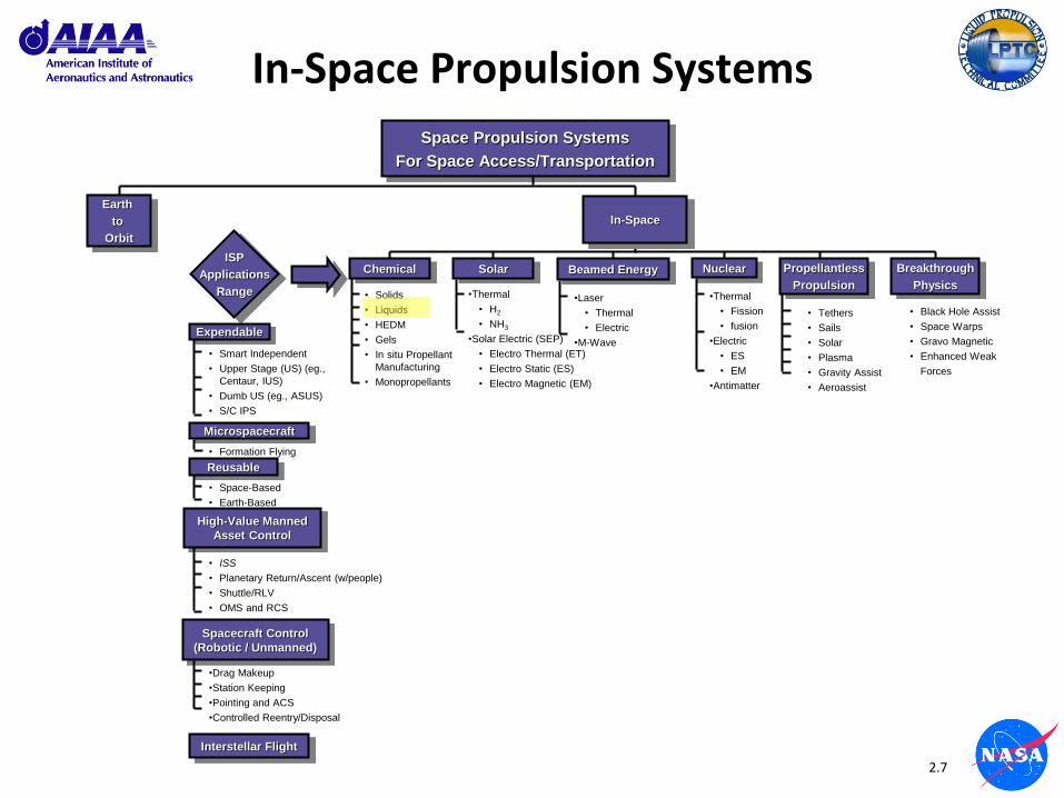
In-Space Propulsion Systems
Space Propulsion Systems
For Space Access/Transportation
Earth
to
Orbit
ISP
Applications
Range
Expendable
• Smart Independent
• Upper Stage (US) (eg.,
Centaur, IUS)
• Dumb US (eg., ASUS)
• S/C IPS
Microspacecraft
• Formation Flying
Reusable
• Space-Based
• Earth-Based
• Solids
• Liquids
• HEDM
• Gels
• In situ Propellant
Manufacturing
• Monopropellants
•Thermal
• H2
• NH3
•Solar Electric (SEP)
• Electro Thermal (ET)
• Electro Static (ES)
• Electro Magnetic (EM)
High-Value Manned
Asset Control
• ISS
• Planetary Return/Ascent (w/people)
• Shuttle/RLV
• OMS and RCS
• Space Tourism
•Drag Makeup
•Station Keeping
•Pointing and ACS
•Controlled Reentry/Disposal
Interstellar Flight
Spacecraft Control
(Robotic / Unmanned)
Chemical Solar
In-Space
Breakthrough
Physics
Propellantless
Propulsion
Beamed Energy Nuclear
•Laser
• Thermal
• Electric
•M-Wave
•Thermal
• Fission
• fusion
•Electric
• ES
• EM
•Antimatter
• Tethers
• Sails
• Solar
• Plasma
• Gravity Assist
• Aeroassist
• Black Hole Assist
• Space Warps
• Gravo Magnetic
• Enhanced Weak
Forces

2.8
LRE Applications
Military
• SSM
– ICBM
– IRBM
– SRBM
– SLBM
• SAM
• ASM
• AAM
• Aircraft Superperformance
Space
• Booster (1st stage)
• Sustainer (2nd stage)
• USE (3rd+ stage)
• OME
• RCS / ACS
• Descent / Ascent
• Experimental Aircraft
RS-25
J-2X
2.9
LRE Applications
• Lift launch vehicle and payload from earth surface to LEO – Requires high thrust forces generated by direct thermal energy
conversion – Two sources of thermal power available today
• Chemical combustion • Nuclear - Not suitable because of radiation emitted
• Transfer payloads from LEO to into higher orbits or into planetary trajectories – Much lower thrust forces required – More options available
• Orbit maintenance, position control, station keeping and spacecraft attitude control – Small pulsing thrust forces required – Many options available
2.10
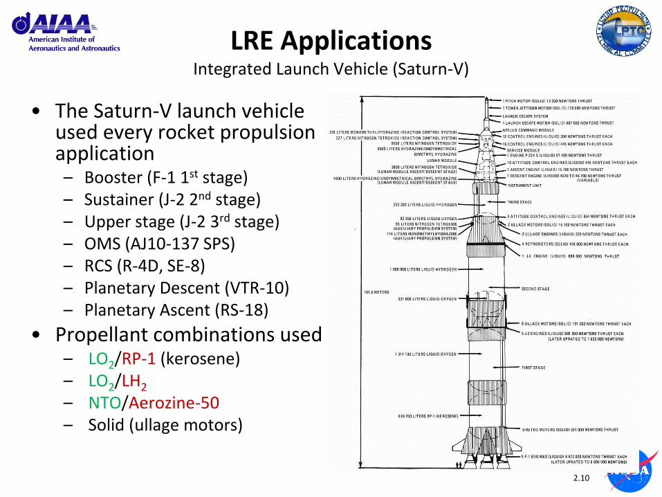
LRE Applications Integrated Launch Vehicle (Saturn-V)
• The Saturn-V launch vehicle used every rocket propulsion application – Booster (F-1 1st stage) – Sustainer (J-2 2nd stage) – Upper stage (J-2 3rd stage) – OMS (AJ10-137 SPS) – RCS (R-4D, SE-8) – Planetary Descent (VTR-10) – Planetary Ascent (RS-18)
• Propellant combinations used – LO2/RP-1 (kerosene) – LO2/LH2
– NTO/Aerozine-50 – Solid (ullage motors)
2.11
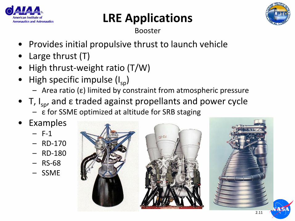
LRE Applications Booster
• Provides initial propulsive thrust to launch vehicle • Large thrust (T) • High thrust-weight ratio (T/W) • High specific impulse (Isp)
– Area ratio (ε) limited by constraint from atmospheric pressure
• T, Isp, and ε traded against propellants and power cycle – ε for SSME optimized at altitude for SRB staging
• Examples – F-1 – RD-170 – RD-180 – RS-68 – SSME
2.12
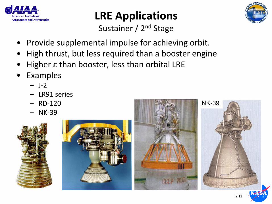
LRE Applications Sustainer / 2nd Stage
• Provide supplemental impulse for achieving orbit. • High thrust, but less required than a booster engine • Higher ε than booster, less than orbital LRE • Examples
– J-2 – LR91 series – RD-120 – NK-39

2.13
LRE Applications Upper Stage Engine (USE)
• Typically applied for final orbital insertion or modification of orbital parameters
• Low to medium thrust (10 – 300 kN) – Dependent on upper stage / mission
requirements
• Propellants typically hypergolic (multi-start, thrust-on-demand) or LO2/LH2 (fewer starts, higher energy, higher orbits, larger payloads) – Russians prefer LO2/kerosene or
NTO/UDMH for their upper stages
• Examples – RL10 family
– Agena
– Vinci RS-72
Agena

2.14
LRE Applications Orbital Maneuvering Engine (OME)
• Moderate Thrust (0.1 – 20 Klbf thrust) – Dependent on vehicle mass and operational requirements
• Long life, multiple starts • Typically pressure-fed hypergolic, radiatively cooled
– Emerging interest in “green” propellants (i.e., LO2/ethanol, HTP)
• Thrust on demand – Minimal preparatory procedures
• Examples – AJ10-137 SPS – AJ10-190 OME – TRW VTE
Aerojet AJ10-137 SPS Engine (Apollo)
NTO+AZ-50 / Pressure-fed / Ablative + Radiation + FFC
T: 20500 lbf Isp: 310.5 sec Pc: 97 psia ε: 62.5:1
2.15
LRE Applications RCS/ACS
• Thrust-on-demand • Throttleable • Pulse-mode • Low thrust (0.001 – 1000 lbf) • Usually pressure-fed monopropellant or hypergolic
bipropellants – Recent elevated interest in “green” propellants (i.e., LO2/ethanol or
HAN)
• Usually ablative or radiatively cooled with FFC – Regenerative cooling not used (thermal soakback)

2.16
LRE Applications RCS Schematic
2.17
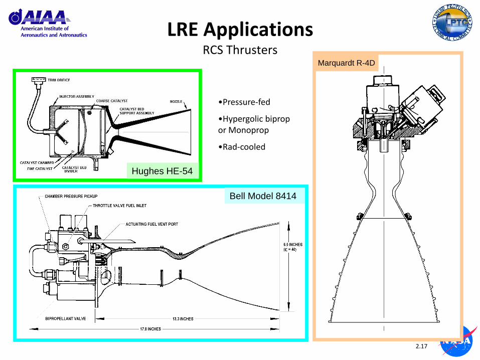
Marquardt R-4D
LRE Applications RCS Thrusters
Hughes HE-54
Bell Model 8414
•Pressure-fed
•Hypergolic biprop or Monoprop
•Rad-cooled

2.18
LRE Applications Planetary Ascent / Descent
• Low/Moderate Thrust (0.6-10 Klbf) • Throttleable (down to 5-10% power) • Thrust-on-Demand
– Fast response – High reliability
• Examples – Aerojet MR-80 – TRW VTR-10 LMDE – Bell/Rkdn LMAE
MR-80 Viking Mars Descent Engine
N2H4 / Pressure-fed / Rad-cooled
T: 632 – 62 lbf (throttleable)
Isp: 210 - 179 sec Pc: 250 – 27 psia

2.19
LRE Applications Planetary Ascent / Descent
TRW VTR-10 LMDE (Apollo)
NTO+AZ-50 / Pressure-fed / Ablative + FFC
T: 9850 – 1050 lbf (throttleable)
Isp: 305 sec Pc: 104 psia
Bell/Rocketdyne RS-18 LMAE (Apollo)
NTO+AZ-50 / Pressure-fed / Ablative + FFC
T: 3500 lbf Isp: 307 sec Pc: 122 psia
MR: 1.6 ε: 45.6:1
2.20
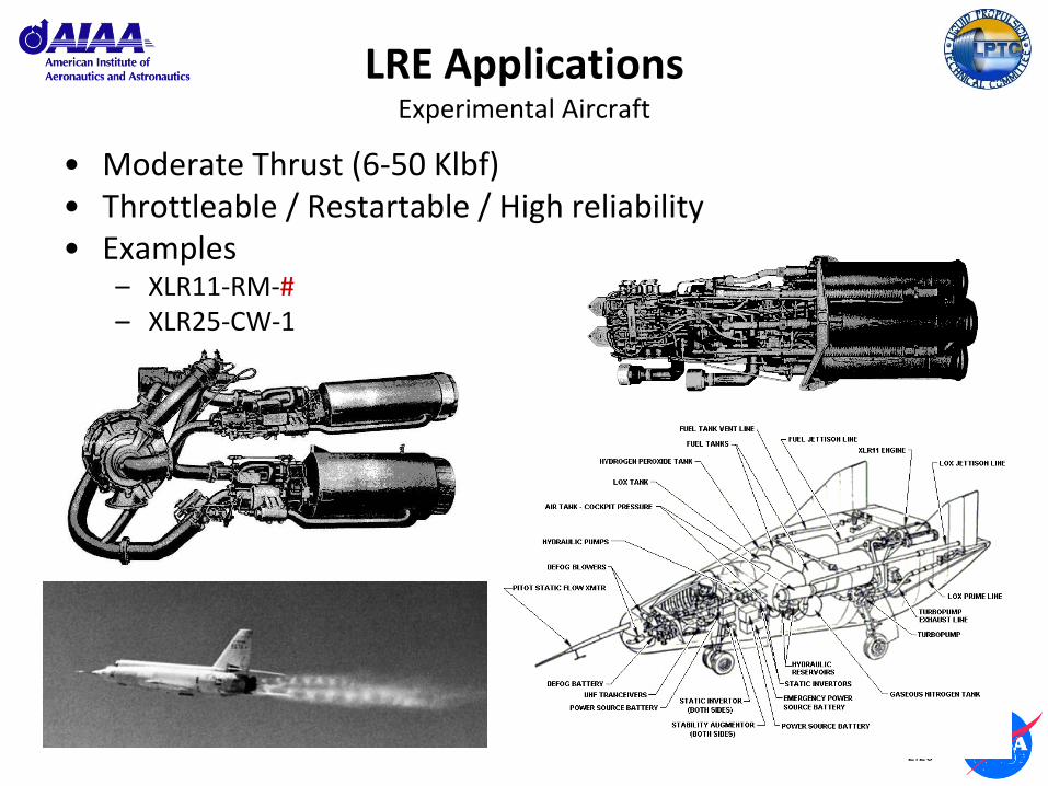
LRE Applications Experimental Aircraft
• Moderate Thrust (6-50 Klbf) • Throttleable / Restartable / High reliability • Examples
– XLR11-RM-# – XLR25-CW-1

2.21
LRE Applications Experimental Aircraft (X-15)
Reaction Motors XLR99-RM-1 • Throttleable (30%) / Restartable / High reliability / Monopropellant GG cycle • LO2 / NH3
• 50 Klbf • Isp: 236 sec • Pc: 600 psia
2.22
Backup / Supplemental Military LRE Applications
(not included in short course material)

3.1
Module 3:
Liquid Propellants
3.2
Terms to Know Liquid Propellants
• Fuel
• Oxidizer
• Monopropellant
• Catalyst
• Bipropellant
• Storable
• Space Storable
• Cryogenic
• Hypergolic
3.3
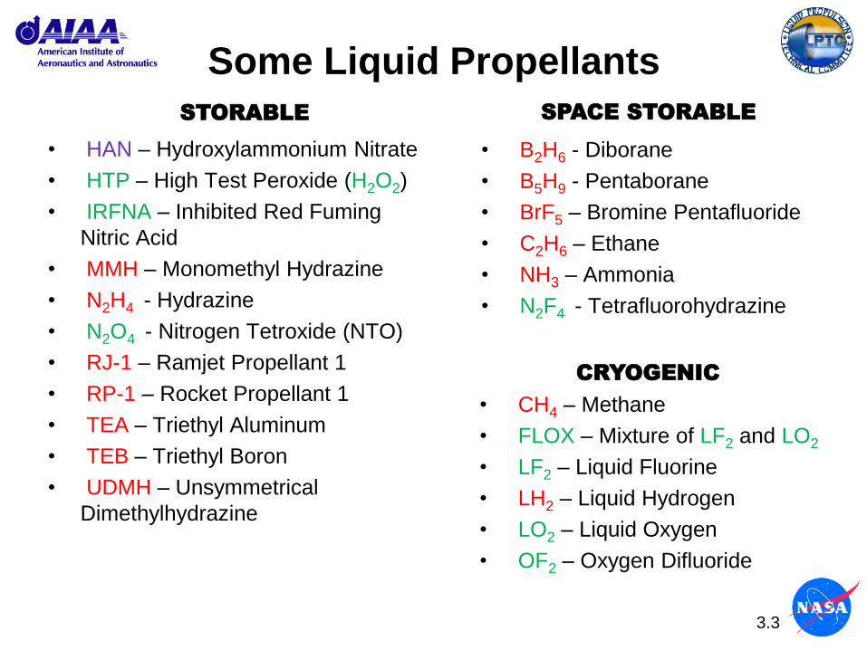
Some Liquid Propellants
• B2H6 - Diborane
• B5H9 - Pentaborane
• BrF5 – Bromine Pentafluoride
• C2H6 – Ethane
• NH3 – Ammonia
• N2F4 - Tetrafluorohydrazine
• HAN – Hydroxylammonium Nitrate
• HTP – High Test Peroxide (H2O2)
• IRFNA – Inhibited Red Fuming
Nitric Acid
• MMH – Monomethyl Hydrazine
• N2H4 - Hydrazine
• N2O4 - Nitrogen Tetroxide (NTO)
• RJ-1 – Ramjet Propellant 1
• RP-1 – Rocket Propellant 1
• TEA – Triethyl Aluminum
• TEB – Triethyl Boron
• UDMH – Unsymmetrical
Dimethylhydrazine
• CH4 – Methane
• FLOX – Mixture of LF2 and LO2
• LF2 – Liquid Fluorine
• LH2 – Liquid Hydrogen
• LO2 – Liquid Oxygen
• OF2 – Oxygen Difluoride
STORABLE SPACE STORABLE
CRYOGENIC
3.4
Propellants
• Propellants are the materials that are combusted by the engine to produce thrust.
• Bipropellant liquid rocket systems consist of a fuel and an oxidizer. They are the most common due to their high performance, but are more complex.
• Several propellants can be used singularly as monopropellants (i.e. HTP, N2H4, UDMH), which release energy when they decompose either when heated or catalyzed.
• The mission / requirements of the vehicle will directly effect the selection of propellants and configuration (power cycle) of the propulsion system(s).
• The primary propellant types to be discussed are:
– Storable
– Space Storable
– Cryogenic
3.5
Propellant Types - Storable
• Storable propellants are liquid at sea level conditions of temperature and pressure and can be stored indefinitely in sealed tanks.
• One drawback of storable propellants is that, with the exception of kerosene-based fuels (RP-1, RJ-1) they are invariably toxic, reactive, corrosive, and difficult to handle.
• Most storable propellant combinations are hypergolic, meaning that they ignite spontaneously when in contact with each other.
– Hypergolic propellant combinations are primarily used for small thruster applications.
– Elimination of the ignition system reduces engine complexity and enables thrust-on-demand capability (quick start with minimal prep) and pulse mode (multiple rapid
• Historical note: The ability to cast large solid rocket motors did not evolve until the late 1950’s, so initial large-thrust rocket propulsion systems used liquid propellants, mostly storables.
– The evolution of RFNA > IRFNA > NTO had strategic impacts (U.S.A. vs. Soviet Union) in terms of performance and storability.

3.6
Propellant Types – Storable Monopropellants
• Monopropellants are storable liquid propellants that can be induced to decompose to a gaseous state in the presence of a catalyst (or contamination) and release heat that can be converted to thrust.
– Catalysts – Shell 405, silver/cobalt plated wire gauze, sodium or potassium permanganate, etc.
– Some monopropellants can be used in bipropellant systems as either a fuel (N2H4, UDMH) or an oxidizer (HTP), which can enable more operational flexibility
• The performance (i.e., Isp) is lower than that of bipropellant systems, but the systems are more simple (higher reliability).
• One drawback of monopropellant systems is that the reactive nature of the propellant requires high standards of cleanliness to prevent uncontrolled decomposition from contaminants.
• Examples – Hydrogen Peroxide (H2O2, HTP) up to 90-98% concentration
– Hydrazine (N2H4) most commonly used
– UDMH (used in GG in RD-119)
– HAN (experimental)

3.7
Propellant Types – Space Storable
• Space storable propellants are liquid in the temperatures of space and generally have a net boiling point greater than 230R.
• They can be stored for longer periods of time than cryogenic propellants when in space and depending on the storage tank design, thermal environment, and tank pressure.
• They are generally more energetic than most storable propellant combinations, but are rarely used due to their extreme toxicity, reactivity and handling difficulties.
• Actual application of space storable propellants in an operational propulsion system is rare due to the toxicity hazards.
– Beginning in the late 1950’s, the USAF studied the use of space storable propellants in upper stages. The findings indicated that the operational hazards did not justify the performance gains.
– The XLR99-RM-1 rocket engine for the X-15 experimental hypersonic aircraft used a LO2/NH3 propellant combination.
3.8
Propellant Types – Cryogenic
• Cryogenic propellants are liquefied gases at extremely low temperatures (approx. 30R to 230R) and are typically the most energetic types of propellants.
• However, they are more difficult to store for any length of time (vaporization losses) and require provisions for venting the propellant tank.
• LO2 and LH2 are the most commonly used liquid cryogenic propellants, and will be used in the J-2X.
– LH2
• Advantages – High performance, excellent coolant
• Disadvantage – Low density (~4.5 lb/ft3 vs. 72 lb/ft3 for LO2, resulting in a disproportionate size in propellant tanks)
– LO2
• Advantages – Non-toxic, high reactivity to fuel (high performance). Only fluorine is a better oxidizer.
• Disadvantage – Not selective about what it uses as fuel. It prefers hydrogen or hydrocarbons, but will consume almost anything with an oxidation potential.

3.9
Backup / Supplemental
3.10
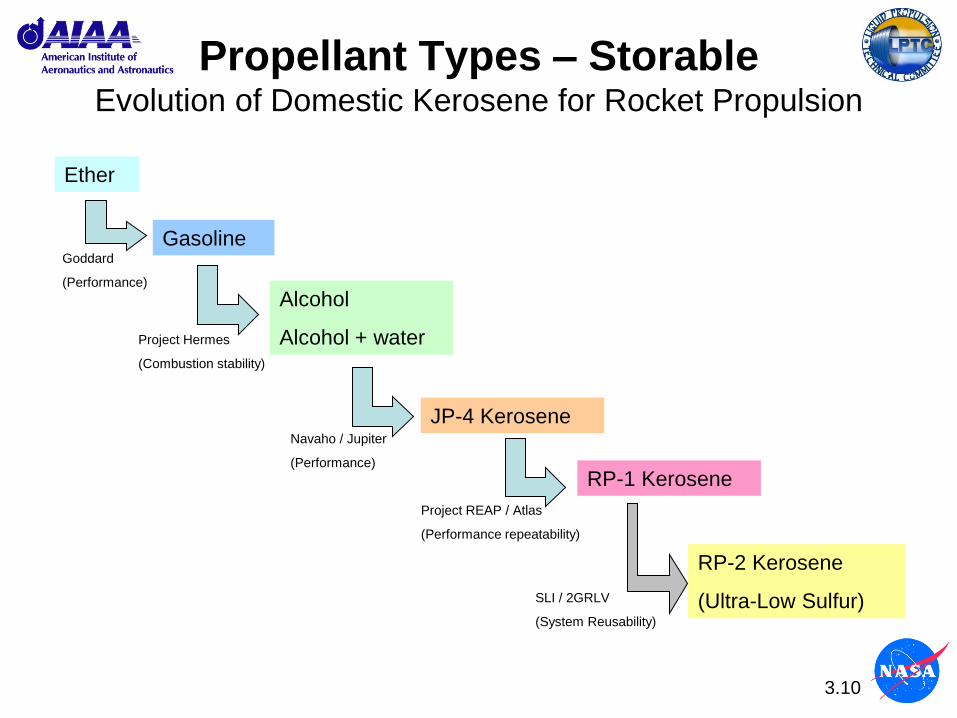
Propellant Types – Storable Evolution of Domestic Kerosene for Rocket Propulsion
Ether
Gasoline
Alcohol
Alcohol + water
JP-4 Kerosene
RP-1 Kerosene
RP-2 Kerosene
(Ultra-Low Sulfur)
Goddard
(Performance)
Project Hermes
(Combustion stability)
Navaho / Jupiter
(Performance)
Project REAP / Atlas
(Performance repeatability)
SLI / 2GRLV
(System Reusability)

3.11
Propellant Types – Storable Kerosene Forms - Domestic
Fuel Formula MW HF
(cal/mol)
Density
(lb/ft3)
JP-4 C10H20 140.27 -63756 48.5
JP-5 C10H19 139.26 -57177 50.97
JP-7 C10H21 141.28 -70187 49.5
JP-9 C652H999 8835.2 -335528 58.12
JP-10 C10H16 136.24 -25219 58.06
RJ-4 C12H20 164.29 -44930 57.66
RJ-5 C140H184 1867.0 +199776 66.17
RJ-6 C700H999 9414.7 -92195 64.3
RP-1 C10H19.5 139.5 -57600 50.3
Quadricyclane C7H8 92.14 +72200 57.36
Source: “Fuels for Airbreathing Propulsion,” G.W. Burdette, H.G. Lacomb, M.J. Stevens, Naval
Weapons Center Technical Memorandum 3045, Feb 1977
3.12
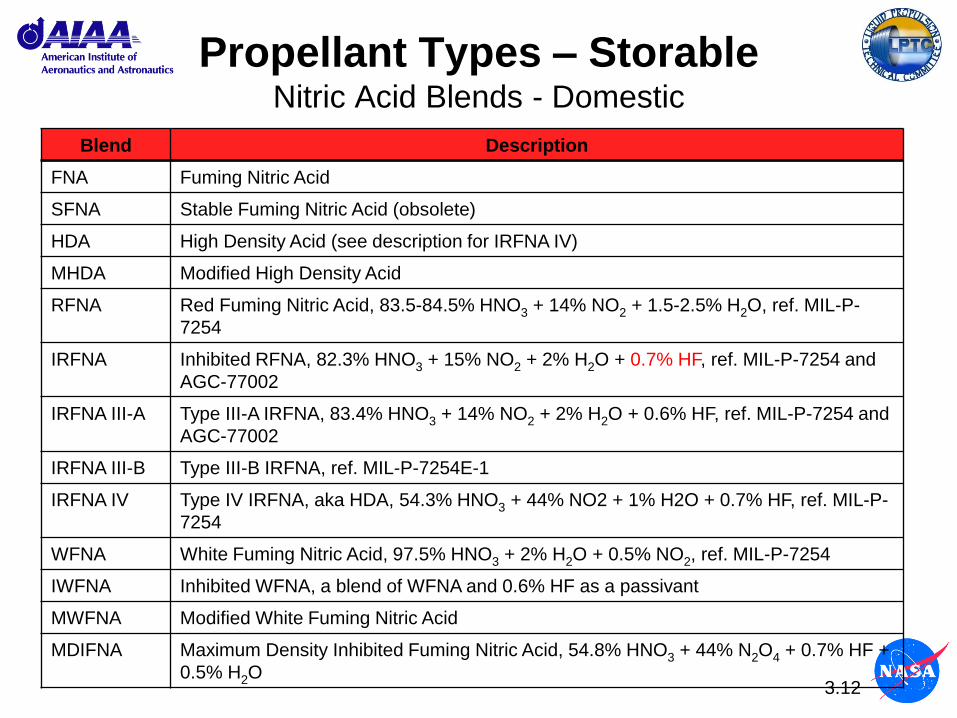
Propellant Types – Storable Nitric Acid Blends - Domestic
Blend Description
FNA Fuming Nitric Acid
SFNA Stable Fuming Nitric Acid (obsolete)
HDA High Density Acid (see description for IRFNA IV)
MHDA Modified High Density Acid
RFNA Red Fuming Nitric Acid, 83.5-84.5% HNO3 + 14% NO2 + 1.5-2.5% H2O, ref. MIL-P-
7254
IRFNA Inhibited RFNA, 82.3% HNO3 + 15% NO2 + 2% H2O + 0.7% HF, ref. MIL-P-7254 and
AGC-77002
IRFNA III-A Type III-A IRFNA, 83.4% HNO3 + 14% NO2 + 2% H2O + 0.6% HF, ref. MIL-P-7254 and
AGC-77002
IRFNA III-B Type III-B IRFNA, ref. MIL-P-7254E-1
IRFNA IV Type IV IRFNA, aka HDA, 54.3% HNO3 + 44% NO2 + 1% H2O + 0.7% HF, ref. MIL-P-
7254
WFNA White Fuming Nitric Acid, 97.5% HNO3 + 2% H2O + 0.5% NO2, ref. MIL-P-7254
IWFNA Inhibited WFNA, a blend of WFNA and 0.6% HF as a passivant
MWFNA Modified White Fuming Nitric Acid
MDIFNA Maximum Density Inhibited Fuming Nitric Acid, 54.8% HNO3 + 44% N2O4 + 0.7% HF +
0.5% H2O

4.1
Module 4:
Power Cycles

4.2
Objective
Continue the overview discussion of liquid propellant rocket engines to focus on the various power cycles that are used to power the turbomachinery.
4.3
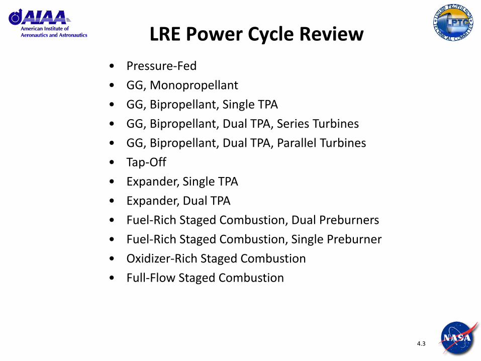
LRE Power Cycle Review
• Pressure-Fed
• GG, Monopropellant
• GG, Bipropellant, Single TPA
• GG, Bipropellant, Dual TPA, Series Turbines
• GG, Bipropellant, Dual TPA, Parallel Turbines
• Tap-Off
• Expander, Single TPA
• Expander, Dual TPA
• Fuel-Rich Staged Combustion, Dual Preburners
• Fuel-Rich Staged Combustion, Single Preburner
• Oxidizer-Rich Staged Combustion
• Full-Flow Staged Combustion
4.4
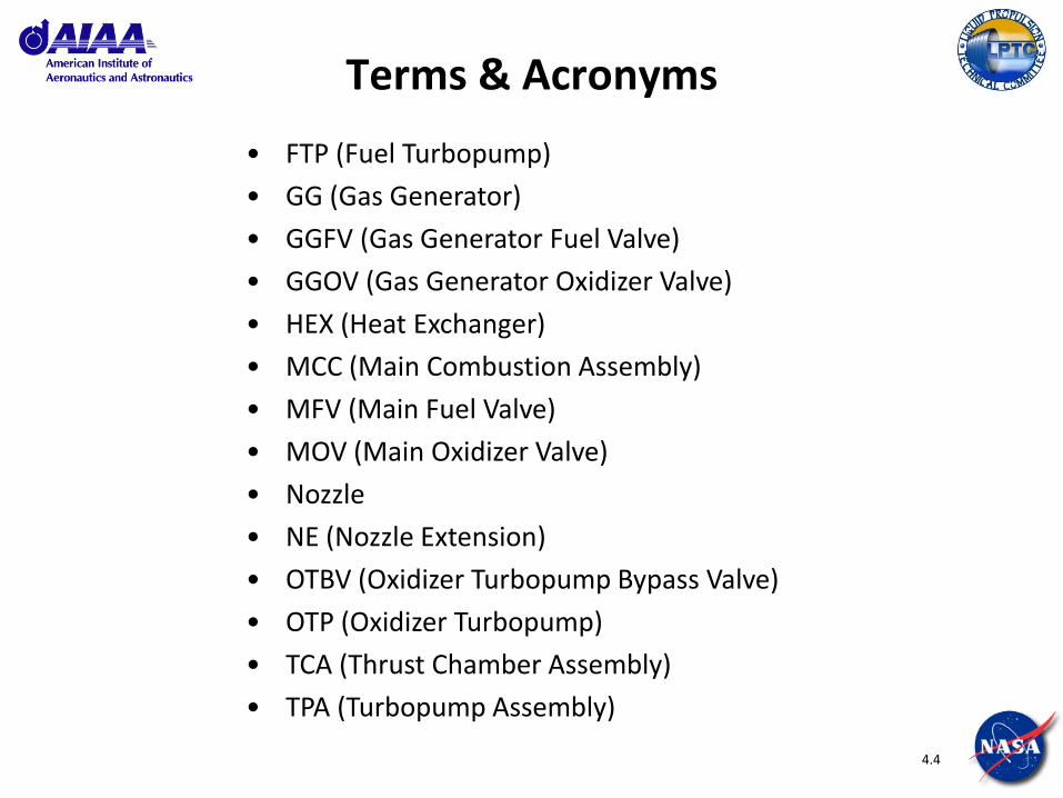
Terms & Acronyms
• FTP (Fuel Turbopump)
• GG (Gas Generator)
• GGFV (Gas Generator Fuel Valve)
• GGOV (Gas Generator Oxidizer Valve)
• HEX (Heat Exchanger)
• MCC (Main Combustion Assembly)
• MFV (Main Fuel Valve)
• MOV (Main Oxidizer Valve)
• Nozzle
• NE (Nozzle Extension)
• OTBV (Oxidizer Turbopump Bypass Valve)
• OTP (Oxidizer Turbopump)
• TCA (Thrust Chamber Assembly)
• TPA (Turbopump Assembly)

4.5
Rocket Engine Cycles
• A rocket engine “cycle” refers to the power cycle that the engine system uses to power the turbopumps to pressurize the propellants.
• A number of thermodynamic cycle options exist • Which one used depends on application or mission requirements • One cycle is not right for every application
• The selection of power cycle can be driven by many factors:
• Propellants
• Performance (thrust, specific impulse)
• Safety / Reliability
• Reusability
• Technical Risk
• Cost / Schedule
• Etc.

4.6
LRE Cycle Uses
Staged Combustion,
Single Chamber
Tripropellant
Staged Combustion,
Dual Preburner
Staged Combustion,
Single PreburnerGas Generator Expander Tap-off
Advantages
Highest integrated
performance available
(closed cycle).
Maximizes propellant
bulk density and Isp.
High performance
(closed cycle). Very
attractive for reusable
applications. Easlier MR
and thrust level throttling
characteristics.
High performance
(closed cycle). Simplier
than multi preburner
options to left. Very
attractive for reusable
applications
Simple cycle, low
production costs, easlier
to develop
High reliability, benign
failure modes
(containted), simple
cycle
Simple cycle with fewer
parts, lower production
costs, easier
maintainability
Disadvantages
Most difficult to develop.
Will be very expensive.
Production cost makes
reusable applications
mandatory. Vehicle must
be very performance
driven such as SSTO.
More difficult to develop
than single PB. Tends to
be very expensive.
Failure modes tend to be
more involved.
Production cost makes
reusable applications
almost mandatory.
More difficult to develop.
Tends to be more
expensive. Failure
modes tend to be more
involved.
Lower performance
because of open cycle.
Performance level makes
this unattactive for most
reusable applications.
Limited to LOX/LH2
propellants only. Limited
performance because of
heat transfer limitations.
Hot gas duct that taps off
from the MCC and mixes
dilluent fuel to regulate
gas temperature. Lower
performance (Open
cycle).
Potential
ApplicationsReusable SSTO.
Booster or upperstage,
reusable rockets
Booster or upperstage,
reusable or expendible
rockets (May depend on
propellant choices)
Booster or upper stage,
expendible rockets
Booster or upperstage,
reusable or expendible
rockets
Booster or upper stage,
expendible rockets
4.7
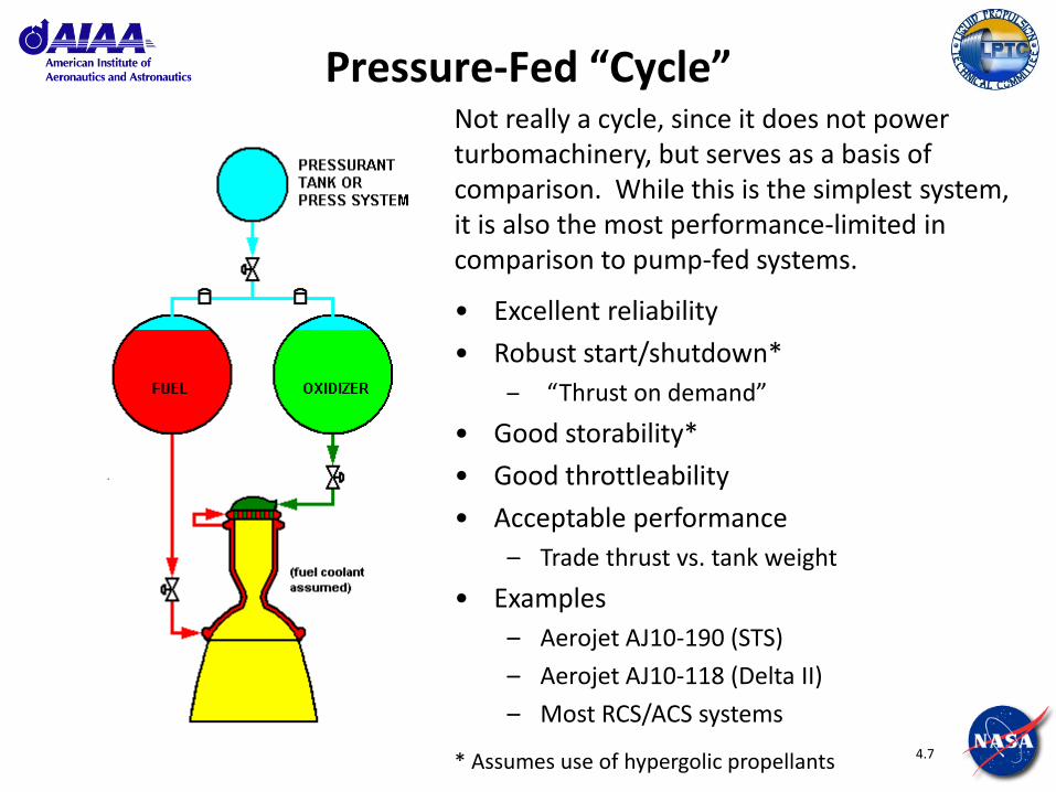
Pressure-Fed “Cycle” Not really a cycle, since it does not power turbomachinery, but serves as a basis of comparison. While this is the simplest system, it is also the most performance-limited in comparison to pump-fed systems.
• Excellent reliability
• Robust start/shutdown*
– “Thrust on demand”
• Good storability*
• Good throttleability
• Acceptable performance
– Trade thrust vs. tank weight
• Examples
– Aerojet AJ10-190 (STS)
– Aerojet AJ10-118 (Delta II)
– Most RCS/ACS systems
* Assumes use of hypergolic propellants
4.8
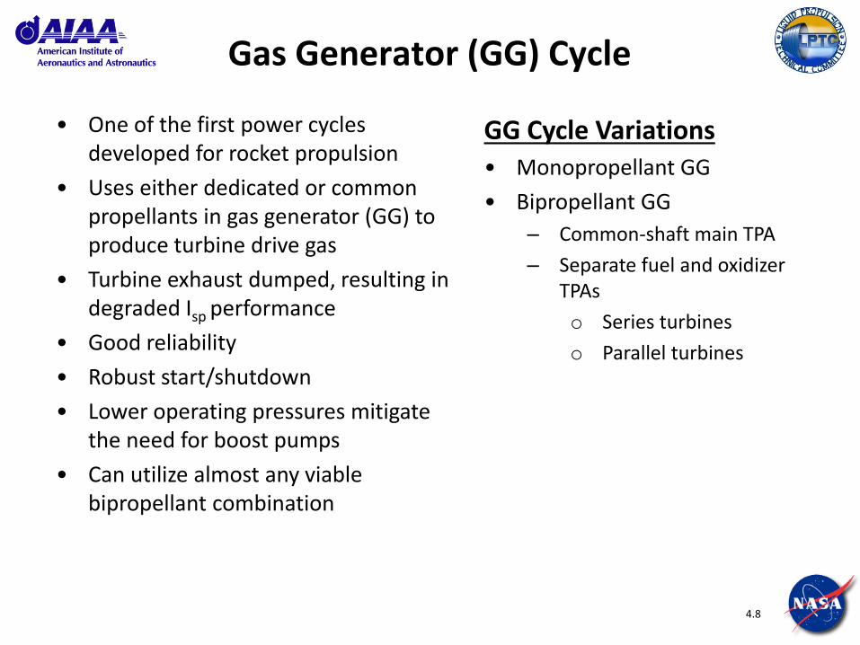
Gas Generator (GG) Cycle
• One of the first power cycles developed for rocket propulsion
• Uses either dedicated or common propellants in gas generator (GG) to produce turbine drive gas
• Turbine exhaust dumped, resulting in degraded Isp performance
• Good reliability
• Robust start/shutdown
• Lower operating pressures mitigate the need for boost pumps
• Can utilize almost any viable bipropellant combination
GG Cycle Variations • Monopropellant GG
• Bipropellant GG
– Common-shaft main TPA
– Separate fuel and oxidizer TPAs
o Series turbines
o Parallel turbines

4.9
Gas Generator (GG) Cycle Monopropellant GG
• Early/original power cycle
• Acceptable performance
– Independent monopropellant control provides more reliable system, but at the cost of increased weight of third propellant
• Examples
– A-4 (V-2)
– A-6 (Navaho-I)
– A-7 (Redstone)
– RD-107/108 (R-7 family)
– XLR99-RM-1 (X-15)
– AR2-3A (F-104)

4.10
Gas Generator (GG) Cycle Bipropellant, Single TPA
• Improved performance over monopropellant GG
– Bootstrap start
– T/W improved by elimination of 3rd propellant
• This cycle works well for propellants with similar fluid properties (i.e., density, viscosity = LO2/RP-1) to allow a common shaft RPM.
• Examples
– F-1
– Atlas MA-2, -3, -5, -5A
– Navaho-II, -III
– MC-1 / Fastrac
– S-3D → H-1 → RS-27
4.11
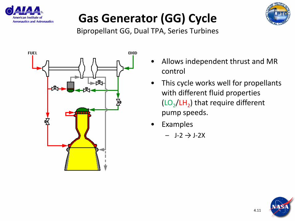
Gas Generator (GG) Cycle Bipropellant GG, Dual TPA, Series Turbines
• Allows independent thrust and MR control
• This cycle works well for propellants with different fluid properties (LO2/LH2) that require different pump speeds.
• Examples
– J-2 → J-2X
4.12
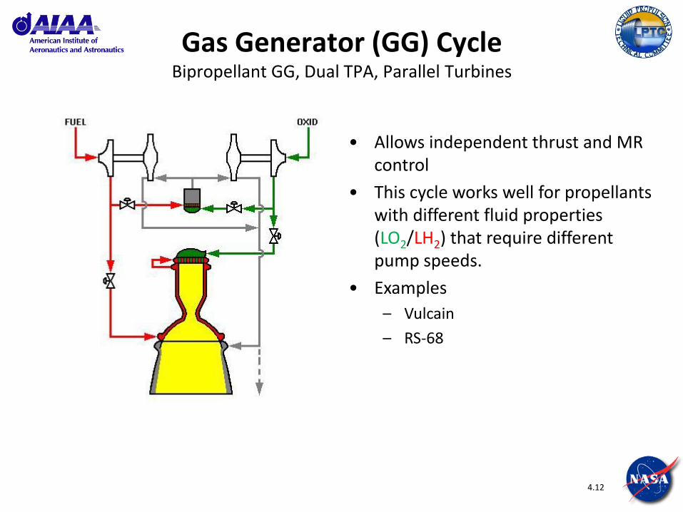
Gas Generator (GG) Cycle Bipropellant GG, Dual TPA, Parallel Turbines
• Allows independent thrust and MR control
• This cycle works well for propellants with different fluid properties (LO2/LH2) that require different pump speeds.
• Examples
– Vulcain
– RS-68

4.13
Tapoff Cycle
• Turbopumps driven by hot gas tapped from main chamber
• Good throttleability
• Low operational experience
• Simplicity offers potential high reliability
• Examples
– J-2S
4.14
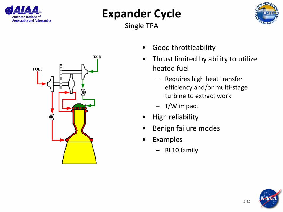
Expander Cycle Single TPA
• Good throttleability
• Thrust limited by ability to utilize heated fuel
– Requires high heat transfer efficiency and/or multi-stage turbine to extract work
– T/W impact
• High reliability
• Benign failure modes
• Examples
– RL10 family
4.15
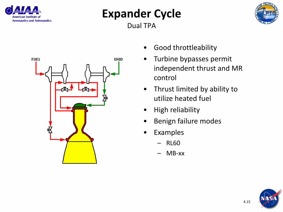
Expander Cycle Dual TPA
• Good throttleability
• Turbine bypasses permit independent thrust and MR control
• Thrust limited by ability to utilize heated fuel
• High reliability
• Benign failure modes
• Examples
– RL60
– MB-xx

4.16
Staged Combustion (SC) Cycle
• Utilizes all propellants to generate thrust
• High performance (thrust, Isp, T/W)
• High Isp requires high operating pressures
• Good reliability, but high operating conditions demand vigilance
• The high operating pressures usually requires the use of boost pumps to increase propellant pressure entering main pumps.
SC Cycle Variations • Fuel-Rich (FRSC)
– Often used with LO2/LH2 propellants
• Oxidizer-Rich (ORSC)
– Often used with LO2/Kerosene propellants
– NTO/UDMH also used
• Full-Flow (FFSC)
– One experimental system developed (IPD) using LO2/LH2 propellants
4.17
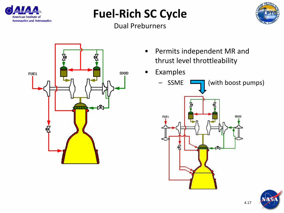
Fuel-Rich SC Cycle Dual Preburners
• Permits independent MR and thrust level throttleability
• Examples
– SSME (with boost pumps)
4.18
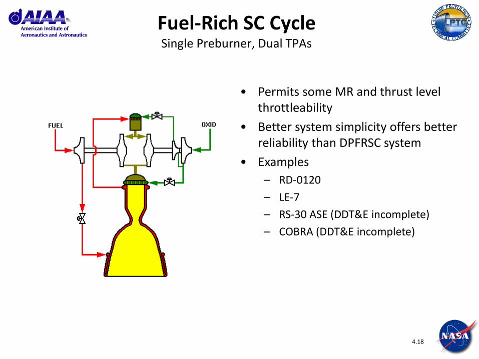
Fuel-Rich SC Cycle Single Preburner, Dual TPAs
• Permits some MR and thrust level throttleability
• Better system simplicity offers better reliability than DPFRSC system
• Examples
– RD-0120
– LE-7
– RS-30 ASE (DDT&E incomplete)
– COBRA (DDT&E incomplete)
4.19
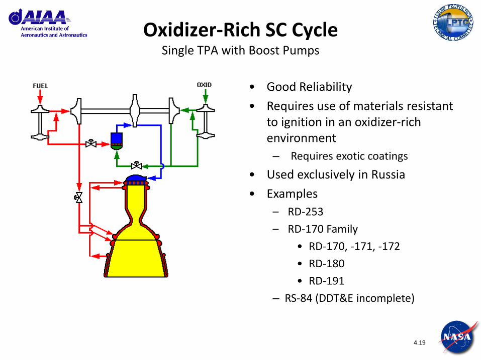
Oxidizer-Rich SC Cycle Single TPA with Boost Pumps
• Good Reliability
• Requires use of materials resistant to ignition in an oxidizer-rich environment
– Requires exotic coatings
• Used exclusively in Russia
• Examples
– RD-253
– RD-170 Family
• RD-170, -171, -172
• RD-180
• RD-191
– RS-84 (DDT&E incomplete)
4.20
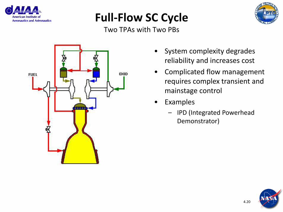
Full-Flow SC Cycle Two TPAs with Two PBs
• System complexity degrades reliability and increases cost
• Complicated flow management requires complex transient and mainstage control
• Examples
– IPD (Integrated Powerhead Demonstrator)

4.21
Other Cycles
• In addition to the primary power cycles already discussed, there are numerous variations of these that can be investigated to pursue higher performance.
• These variations are limited by the different permutations of components and system enhancements that can be integrated.
• Also, occasionally a “wildcat” power cycle will be proposed. Often they will promise high performance, but are hampered by high technical risk and low validated substantiation.
– Dual-expander cycle
– Augmented expander cycle
– Cycles using tripropellants
– Combined cycle system
– …and then there are the real crazy ones…
4.22
Backup Slides Example Engines
4.23
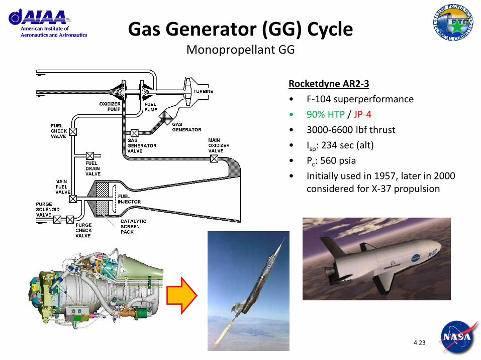
Gas Generator (GG) Cycle Monopropellant GG
Rocketdyne AR2-3
• F-104 superperformance
• 90% HTP / JP-4
• 3000-6600 lbf thrust
• Isp: 234 sec (alt)
• Pc: 560 psia
• Initially used in 1957, later in 2000 considered for X-37 propulsion

4.24
Gas Generator (GG) Cycle Bipropellant GG, Single TPA
NASA/MSFC MC-1 Fastrac
• X-34 hypersonic aircraft
• LO2 / RP-1
• 64 Klbf thrust (vac)
• Isp: 314 sec (vac)
• Pc: 650 psia
4.25
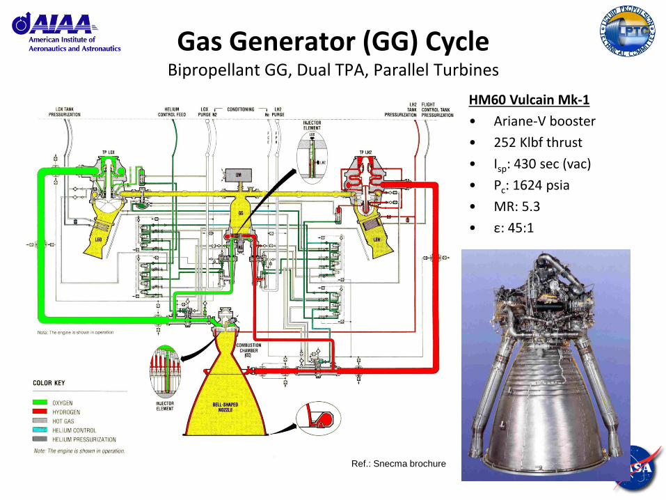
Gas Generator (GG) Cycle Bipropellant GG, Dual TPA, Parallel Turbines
HM60 Vulcain Mk-1
• Ariane-V booster
• 252 Klbf thrust
• Isp: 430 sec (vac)
• Pc: 1624 psia
• MR: 5.3
• ε: 45:1
Ref.: Snecma brochure
4.26
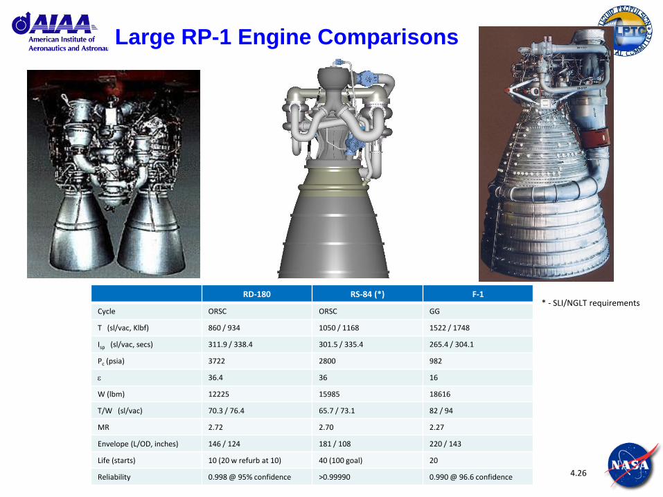
Large RP-1 Engine Comparisons
* - SLI/NGLT requirements RD-180 RS-84 (*) F-1
Cycle ORSC ORSC GG
T (sl/vac, Klbf) 860 / 934 1050 / 1168 1522 / 1748
Isp (sl/vac, secs) 311.9 / 338.4 301.5 / 335.4 265.4 / 304.1
Pc (psia) 3722 2800 982
36.4 36 16
W (lbm) 12225 15985 18616
T/W (sl/vac) 70.3 / 76.4 65.7 / 73.1 82 / 94
MR 2.72 2.70 2.27
Envelope (L/OD, inches) 146 / 124 181 / 108 220 / 143
Life (starts) 10 (20 w refurb at 10) 40 (100 goal) 20
Reliability 0.998 @ 95% confidence >0.99990 0.990 @ 96.6 confidence

5.1
Module 5:
Subsystems & Components
Oxidizer Preburner
HPOTP
LPFTP
Controller
Propellant Valves
Hydraulic Actuators
Nozzle
MCC
Hot Gas Manifold
Fuel Preburner
LPOTP
HPFTP
SSME Main Injector
5.2
Objective
Continue the overview discussion of liquid propellant rocket engines to focus on the different components used to form the engine system.
5.3
Subsystems and Components
• Turbomachinery
• Combustion Devices
• Valves & Actuators
• Engine Control System
• Ancillary Systems
• Engine Integration Hardware
5.4
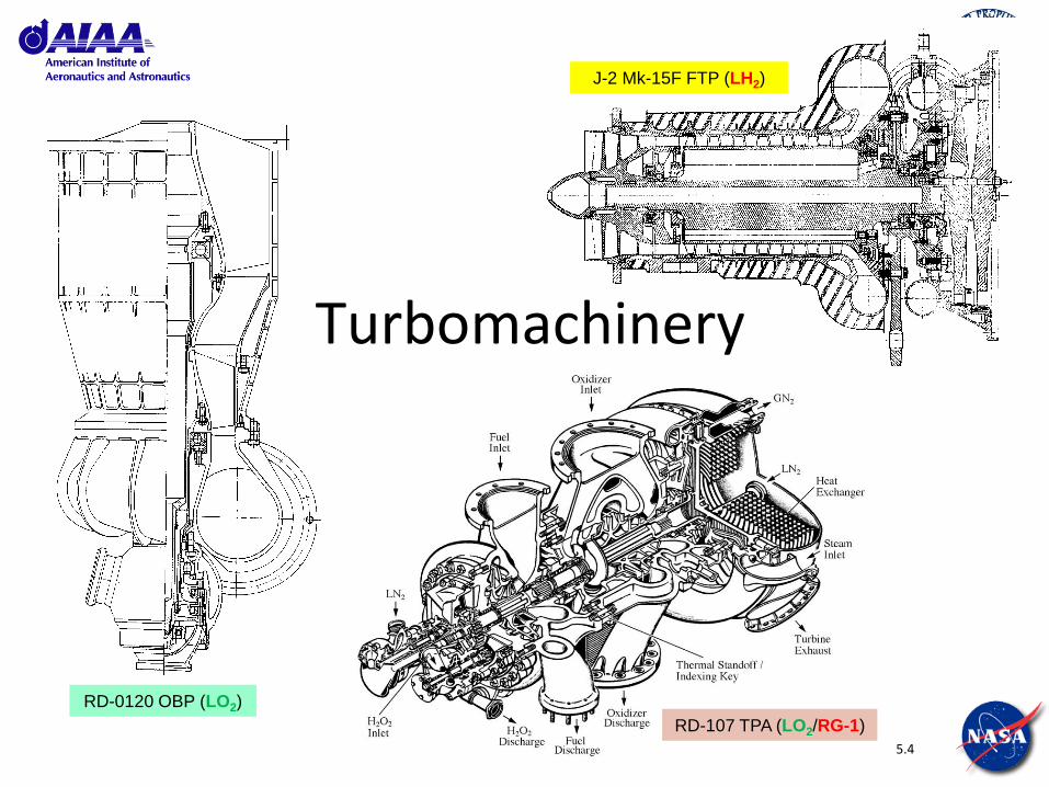
Turbomachinery
RD-0120 OBP (LO2)
J-2 Mk-15F FTP (LH2)
RD-107 TPA (LO2/RG-1)
5.5
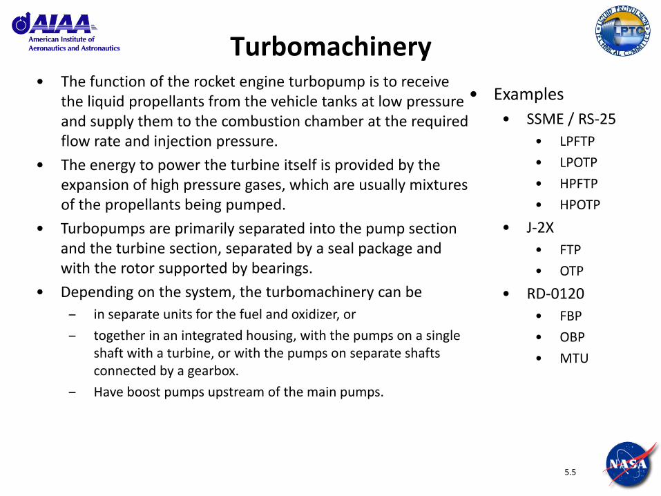
Turbomachinery • The function of the rocket engine turbopump is to receive
the liquid propellants from the vehicle tanks at low pressure and supply them to the combustion chamber at the required flow rate and injection pressure.
• The energy to power the turbine itself is provided by the expansion of high pressure gases, which are usually mixtures of the propellants being pumped.
• Turbopumps are primarily separated into the pump section and the turbine section, separated by a seal package and with the rotor supported by bearings.
• Depending on the system, the turbomachinery can be
– in separate units for the fuel and oxidizer, or
– together in an integrated housing, with the pumps on a single shaft with a turbine, or with the pumps on separate shafts connected by a gearbox.
– Have boost pumps upstream of the main pumps.
• Examples
• SSME / RS-25
• LPFTP
• LPOTP
• HPFTP
• HPOTP
• J-2X
• FTP
• OTP
• RD-0120
• FBP
• OBP
• MTU

5.6
Power Density

5.7
Turbopump Anatomy • Turbopumps have most of the same basic types of parts. Almost all
turbopumps currently in use rely on centrifugal impellers
– Housing / volute (not shown below)
– Impeller
– Inducer
– Shaft
– Turbine
– Bearings
– Seals
5.8
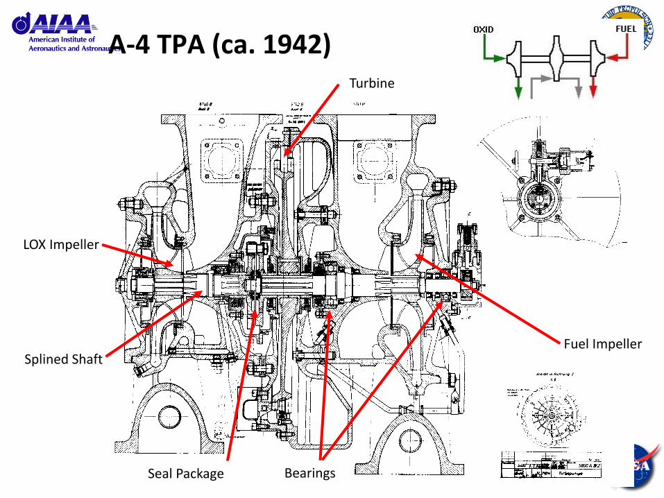
A-4 TPA (ca. 1942)
LOX Impeller
Fuel Impeller
Turbine
Bearings Seal Package
Splined Shaft
5.9
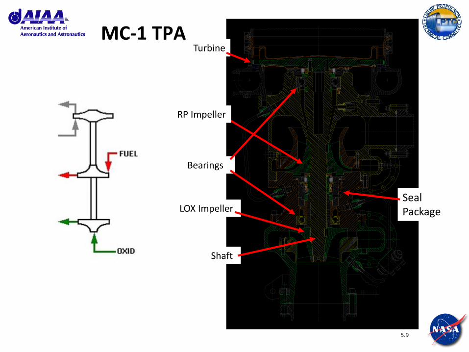
MC-1 TPA
LOX Impeller
RP Impeller
Turbine
Bearings
Seal Package
Shaft

5.10
Bearings
• Bearing packages are used to securely support the turbopump rotor as it rotates at operational speeds. They are designed to tolerate radial and axial loads.
• Ball – most commonly used
• Roller – fewer, but with higher radial load capacity
• Hydrostatic – useful with fuel turbopumps
Ref
: B
rita
nn
ica.
com
Ref
: W
ikip
edia
.co
m &
U.S
. Pat
ent
Off
ice

5.11
Seals
• Seals are internal assemblies that are essential to prevent uncontrolled mixing of fluids (propellants, hot turbine gas) in the turbopump.
• Depending on the fluids being separated, there are multiple options available. More common examples include:
• Labyrinth “laby” seal - fluorocarbon seals that contact ridges around the impeller face and control the amount of propellant flow around the impeller shrouds.
• Lift-off seal – used in LH2 TPA and acts as a check valve permitting flow in only one direction. It prevents LH2 leakage into the turbine end of the turbopump prior to engine start and after engine cutoff. During engine start, a pressure unbalance develops across the seal to offset the spring load and retract the seal, allowing liquid hydrogen to enter and cool the turbine end.
• Intermediate seal – uses a barrier purge in oxidizer TPAs to prevent internal mixing of the oxidizer being pumped with the hot fuel-rich turbine drive gas.
Ref
: A
nsw
ers.
com
Labyrinth “Laby” seal
5.12
Turbo Concerns - Cavitation • What is cavitation?
• The formation of bubbles in the propellant flow when the static pressure in the fluid flow becomes less than the fluid’s vapor pressure.
• Cavitation can occur when the pump inlet pressure is incompatible (lower) with the rotational speed and suction performance of the inducer.
• Why is cavitation bad? What can happen? • Immediate drop-off of exit flow and pressure – can cause LOX-rich excursion (high MR)
if fuel pump excessively cavitates. LOX pump cavitation is less severe and will cause the engine system to power down.
• Elimination of hydraulic brake to turbopump rotor – can cause overspeed and possible rotor burst.
• Material erosion of inducer impeller – hardware damage and progressive degradation of pump performance.
• How is cavitation prevented? • Design using experience and validated analytical codes.
• Extensive testing and data analysis of the inducer/impeller at the part, component, subsystem and system level to validate design and identify the “no-fly” zones.
• Post-test inspections of inducer/impeller surfaces to check for material degradation.
• Redlines on the propellant inlet pressure to shutdown the engine.
5.13
Turbo Concerns – Rotordynamic Instability • What is rotordynamic instability?
• Can occur when the rotor exhibits an excessive rotational imbalance that exceeds the ability of the bearings to control. Influenced by the stiffness of the bearings, the operational speed of the turbopump and the balance of the rotor.
• Why is rotordynamic instability bad? What can happen? • Rapid degradation of seals and bearings – accelerated increase in instability. Can
liberate bearing and seal material into propellant flow, causing additional damage.
• Rubbing between stationary and rotating parts – can cause friction ignition.
• How is rotordynamic instability prevented? • Design using experience and validated analytical codes with emphasis on rotor design
and bearing selection.
• Progressive balance testing and adjustment during assembly
• Redlines on the turbopump vibration measured by accelerometers to shutdown the engine during testing. Accel redlines typically not used on flight to prevent false cut.

5.14
Combustion Devices
RD-170 PB
M-1 Main Injector
A-4 TCA
RD-119 Monopropellant GG

5.15
Combustion Devices
• Combustion Devices are components responsible for the production and control of the combustion process.
• GG (Gas Generator)
• MCC (Main Combustion Assembly)
• Nozzle
• NE (Nozzle Extension)
• Preburner
• TCA (Thrust Chamber Assembly)
• Start & Ignition System
• Examples
• SSME / RS-25
• FPB
• OPB
• MCC
• Nozzle
• J-2X
• GG
• MCE
• Nozzle
• Nozzle Ext.
5.16
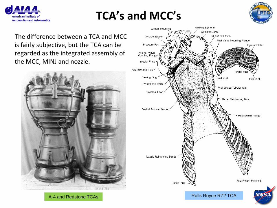
TCA’s and MCC’s
The difference between a TCA and MCC is fairly subjective, but the TCA can be regarded as the integrated assembly of the MCC, MINJ and nozzle.
Rolls Royce RZ2 TCA A-4 and Redstone TCAs
5.17
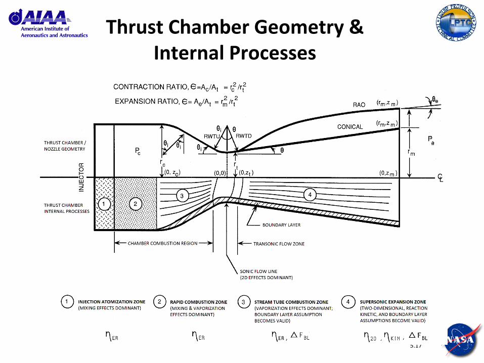
Thrust Chamber Geometry & Internal Processes
5.18
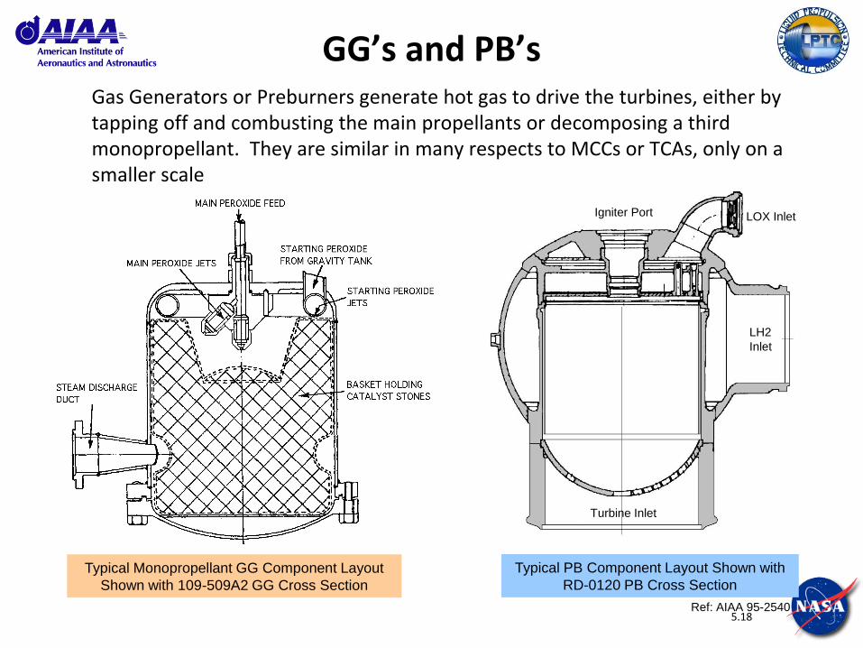
GG’s and PB’s Gas Generators or Preburners generate hot gas to drive the turbines, either by tapping off and combusting the main propellants or decomposing a third monopropellant. They are similar in many respects to MCCs or TCAs, only on a smaller scale
Typical PB Component Layout Shown with
RD-0120 PB Cross Section
Typical Monopropellant GG Component Layout
Shown with 109-509A2 GG Cross Section
LOX Inlet
LH2
Inlet
Turbine Inlet
Igniter Port
Ref: AIAA 95-2540
5.19
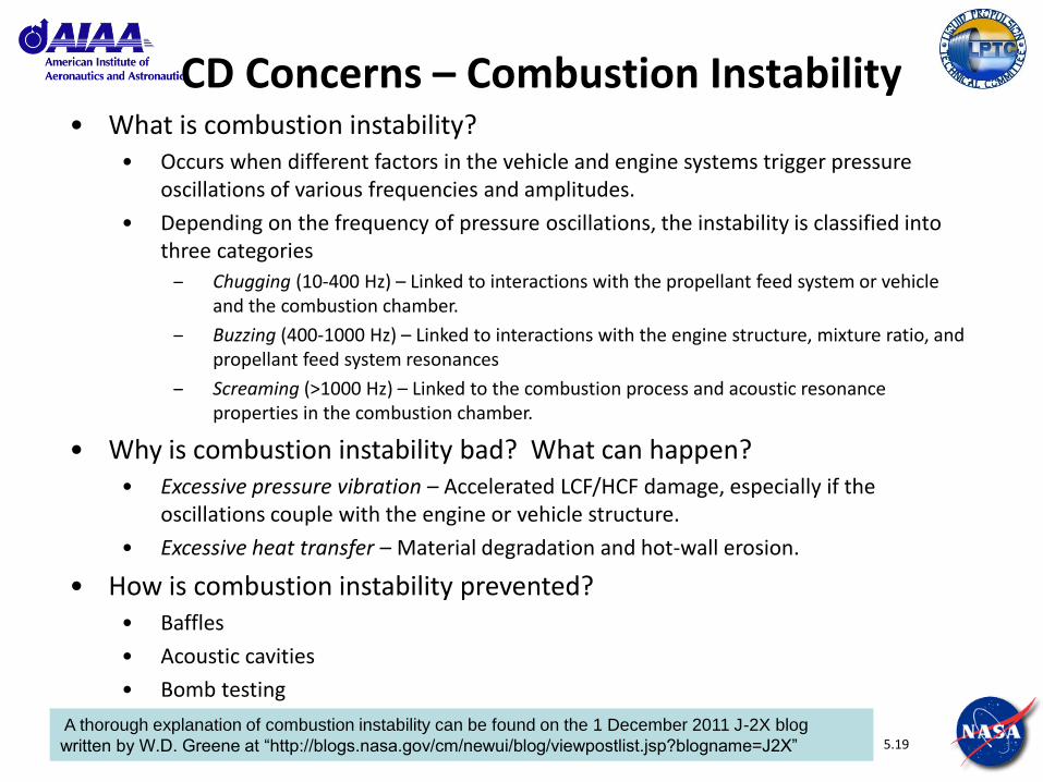
CD Concerns – Combustion Instability • What is combustion instability?
• Occurs when different factors in the vehicle and engine systems trigger pressure oscillations of various frequencies and amplitudes.
• Depending on the frequency of pressure oscillations, the instability is classified into three categories
– Chugging (10-400 Hz) – Linked to interactions with the propellant feed system or vehicle and the combustion chamber.
– Buzzing (400-1000 Hz) – Linked to interactions with the engine structure, mixture ratio, and propellant feed system resonances
– Screaming (>1000 Hz) – Linked to the combustion process and acoustic resonance properties in the combustion chamber.
• Why is combustion instability bad? What can happen? • Excessive pressure vibration – Accelerated LCF/HCF damage, especially if the
oscillations couple with the engine or vehicle structure.
• Excessive heat transfer – Material degradation and hot-wall erosion.
• How is combustion instability prevented? • Baffles
• Acoustic cavities
• Bomb testing
A thorough explanation of combustion instability can be found on the 1 December 2011 J-2X blog
written by W.D. Greene at “http://blogs.nasa.gov/cm/newui/blog/viewpostlist.jsp?blogname=J2X”

5.20
Start & Ignition • The start system provides the initial pressure impulse to the system to
bootstrap the power cycle.
– Tank head – RS-25, RL10
– GHe spin – J-2X
– Solid propellant GG (SPGG) – J-2S
• The ignition system provides the energy pulse required to initiate combustion. Each combustion device in the system generally requires an independent ignition system as the timing is usually different within the start transient. The required pulse level depends on the propellants.
– Spark –most LO2/LH2 engines
– Pyrotechnic – used largely in GGs where an energy pulse is adequate
– Hypergolic (TEA/TEB) – most LO2/RP-1 engines
– Laser – relatively low TRL, but shows promise in terms of flexibility and control.
– Fluorine injection – hypergolic with hydrogen
TEA/TEB – Triethyl Aluminum/Triethyl Boron (a storable fuel blend that is hypergolic with oxygen)

5.21
Valves & Actuators RZ.2 Butterfly MOV
Poppet Valve

5.22
Valves & Actuators
• Valves
• Main Propellant Valves (MOV, MFV)
• Secondary Propellant Valves
• GG Valves (GGFV, GGOV)
• Preburner Valves (FPOV, OPOV)
• Chamber Coolant Valve (CCV)
• Hot Gas Valves (OTBV)
• Ancillary Valves
• Purge Valves
• Check Valves
• Solenoid Valves
• Actuators
• Pneumatic/Hydraulic
• Electro-mechanical
• Examples
• SSME / RS-25
• MFV
• MOV
• FPOV
• OPOV
• CCV
• J-2X
• MFV
• MOV
• GGFV
• GGOV
• OTBV
5.23
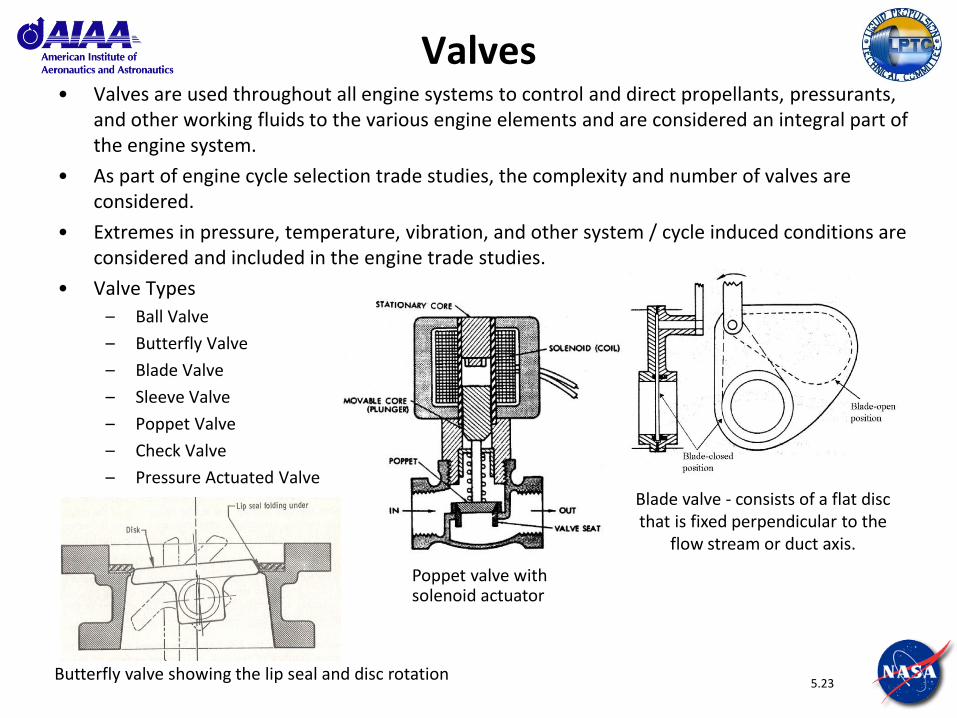
Valves • Valves are used throughout all engine systems to control and direct propellants, pressurants,
and other working fluids to the various engine elements and are considered an integral part of the engine system.
• As part of engine cycle selection trade studies, the complexity and number of valves are considered.
• Extremes in pressure, temperature, vibration, and other system / cycle induced conditions are considered and included in the engine trade studies.
• Valve Types
– Ball Valve
– Butterfly Valve
– Blade Valve
– Sleeve Valve
– Poppet Valve
– Check Valve
– Pressure Actuated Valve Blade valve - consists of a flat disc that is fixed perpendicular to the
flow stream or duct axis.
Poppet valve with solenoid actuator
Butterfly valve showing the lip seal and disc rotation

5.24
Actuators • Most valves require an operator or actuator.
• Types of actuators
– Solenoid
– Hydraulic
– Pneumatic
– Electromechanical
• Design Considerations
– Fluid Medium
– Fluid Temperature
– Fluid Pressure
– Flow Capacity
– Flow Characteristics
– Leakage
– Operating Life
– Control Requirements
– Loads and Environments
Main propellant valve hydraulic actuator for SSME
Electromechanical Actuator

5.25
Control System
5.26
Engine Control System (J-2X) • Control of the J-2X engine is accomplished physically by opening valves that
control the flow of propellants to the combustion devices along with properly timed ignition and pressurized helium spin to initiate engine start, and by closing the valves to stop propellant flow to shutdown the engine.
• The control system consists of components required to perform the functions of starting and shutting down the engine. Four subsystems work together to accomplish these functions:
– engine control subsystem
– propellant valves subsystem
– ancillary valves subsystem
– pneumatic subsystem
• The engine control system has open loop control authority over the engine. In other words, the J-2X control system does not have a feedback (i.e., closed) loop like RS-25 to control and self correct the positions of the propellant valves or engine parameters, like chamber pressure or engine thrust. The engine operating level (thrust, mixture ratio) is controlled by orifices located throughout the engine.
5.27
Engine Control System (J-2X)
• The J-2X engine control system is comprised of the following components:
– Dual Channel Engine Control Unit (ECU)
– Main Injector Exciter Unit (MIEU)
– Pneumatic Actuator Control Assembly (PACA)
– Pneumatic Purge Control Assembly (PPCA)
– Propellant Valves
– Ancillary System Valves
– Health Monitoring Instrumentation
– Critical Instrumentation
• The engine control system performs engine control functions:
– open loop control of the five main propellant valves via pneumatic solenoids
– sequence control of the ancillary valves for purge, bleed, and engine ignition
– sequence control of two GG pyrotechnic devices and main injector spark exciter for engine ignition
– provide engine initiated shutdown status to the vehicle
5.28
Engine Control System (J-2X)
• The engine control system performs engine health monitoring functions:
– monitor operational flight sensors for engine status and health conditions
– perform commanded engine checkout
– provide operational flight sensor data to vehicle
• The Engine Controller Unit (ECU) receives a command to initiate engine start from the vehicle. The ECU actuates propellant valves using a solenoid driver, which subsequently opens a solenoid to pressurize the pneumatic actuator on the propellant valve. The ECU also activates a spark exciter which is used in the ASI system to start ignition in the main chamber and pyrotechnic igniters to start ignition in the GG. The ancillary valves participate by controlling functions such as purge and bleed.
5.29
Ancillary Systems
5.30
Ancillary Systems
• Major system, subsystem and components have been shown to accomplish the primary engine functions. In addition, LREs also include ancillary functionality in support of the major engine functions. These functions are accomplished by the complex plumbing of minor fluid lines, which perform the following:
– Pre-start conditioning of the engine, facilitated by the bleed system
– Supplying pressurants to the vehicle for tank pressurization, facilitated by the tank pressurization system
– Engine start, facilitated by the helium spin start system and the augmented spark ignition system
– Valve actuation, facilitated by the pneumatic actuation system
– Engine purging, facilitated by the purge system
– Routing of propellant leakage, facilitated by the drain system

5.31
Engine Integration Hardware

5.32
Engine Integration Hardware
• HEX (Heat Exchanger)
• Pogo Suppressor
• Gimbal
• Brackets
• Rigid Ducts
• Flex Ducts
• Small lines (bleeds, purges)

5.33
Backup

5.34
Additional References
• General
• NASA-SP 8000 series: ~20 publically-available documents developed in the 1970’s that provide detailed insight into most LRE components. For example:
o NASA SP-8109, “Liquid Rocket Engine Centrifugal Flow Turbopumps,” 1973 http://ntrs.nasa.gov/archive/nasa/casi.ntrs.nasa.gov/19740020848_1974020848.pdf
• Turbomachinery
• Stangeland, M.L., “Turbopumps for Liquid Rocket Engines,” PWR Threshold, 1988 http://www.pwrengineering.com/articles/turbopump.htm
Related Documents