TOPIC 2: LATERAL EARTH PRESSURE BY: ENGR AZHANI ZUKRI BAA3513 SEMI2013/14

Welcome message from author
This document is posted to help you gain knowledge. Please leave a comment to let me know what you think about it! Share it to your friends and learn new things together.
Transcript
TOPIC 2:
LATERAL EARTH PRESSURE
BY: ENGR AZHANI ZUKRI
BAA3513 SEMI2013/14
Learning Outcomes
Introduction to retaining walls and
earth pressures
Lateral earth pressure – Theory of
elasticity
Rankine’s theory of earth pressure
(horizontal and sloping backfill)
Coulomb’s theory of earth pressure
Braced cut BAA3513 SEMI2013/14
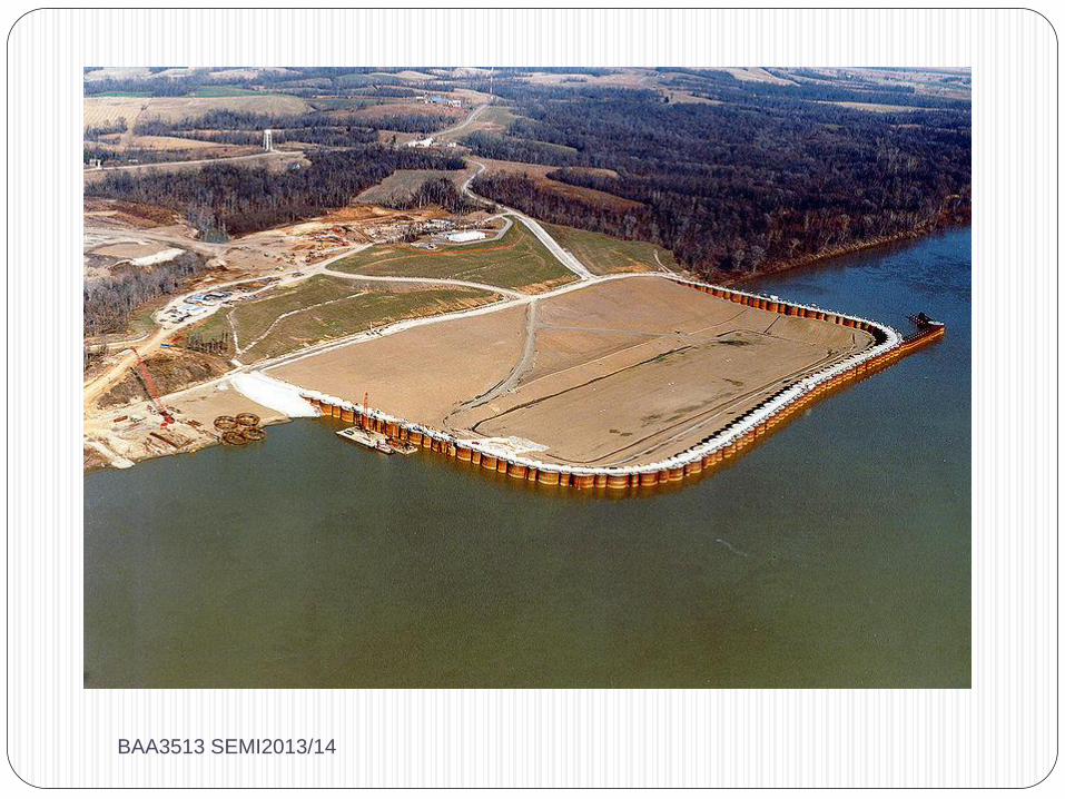
Introduction
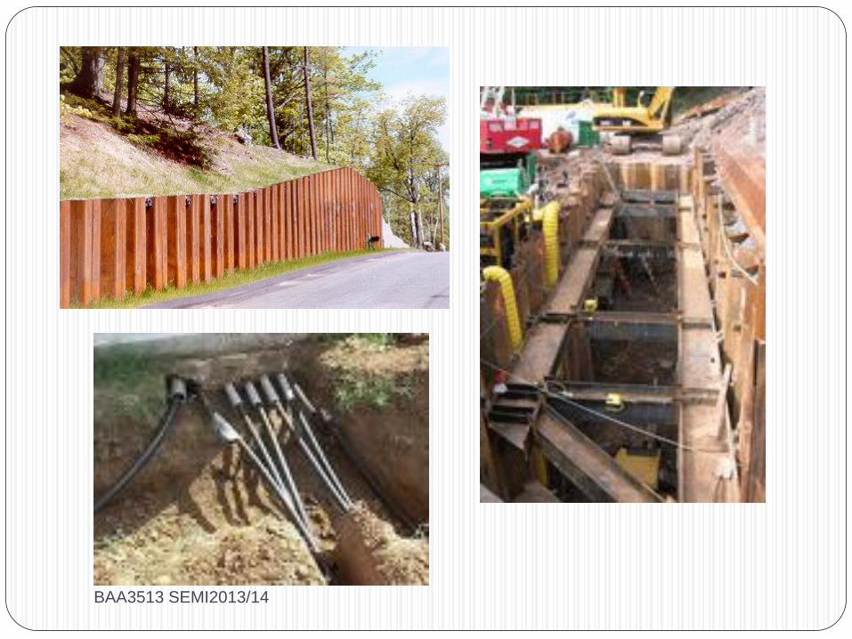
Lateral earth pressure estimation
are crucial to structures such as
retaining walls, sheet piles walls,
buried pipes, basement walls,
braced excavation, cofferdams
and others.
BAA3513 SEMI2013/14
BAA3513 SEMI2013/14
BAA3513 SEMI2013/14
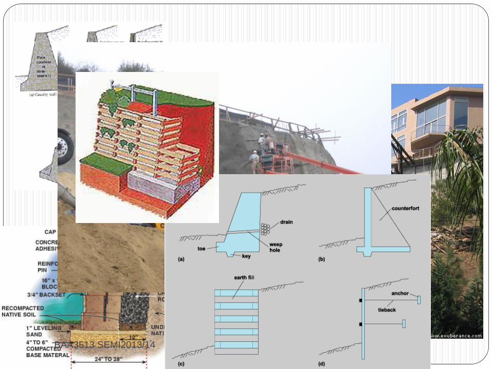
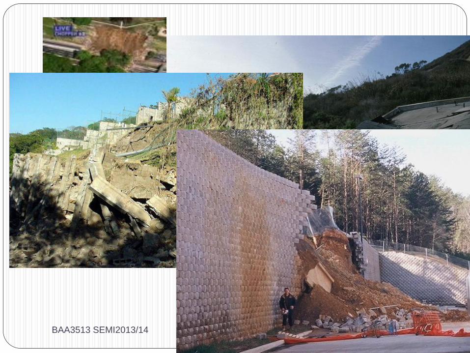
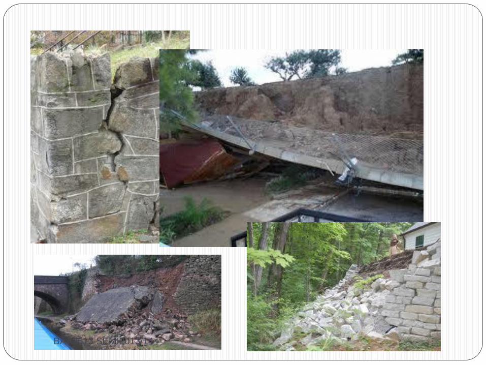
Retaining walls
BAA3513 SEMI2013/14
BAA3513 SEMI2013/14
What are Factors that
should be considered when
selecting the type of
retaining wall?
RETAINING WALL
BAA 3513 SEMI2013/14 9
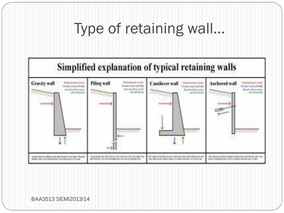
Type of retaining wall…
BAA3513 SEMI2013/14
Earth pressures
There are 3 condition that need to be consider
i) At rest pressure
ii) Active pressure
iii) Passive pressure
BAA3513 SEMI2013/14
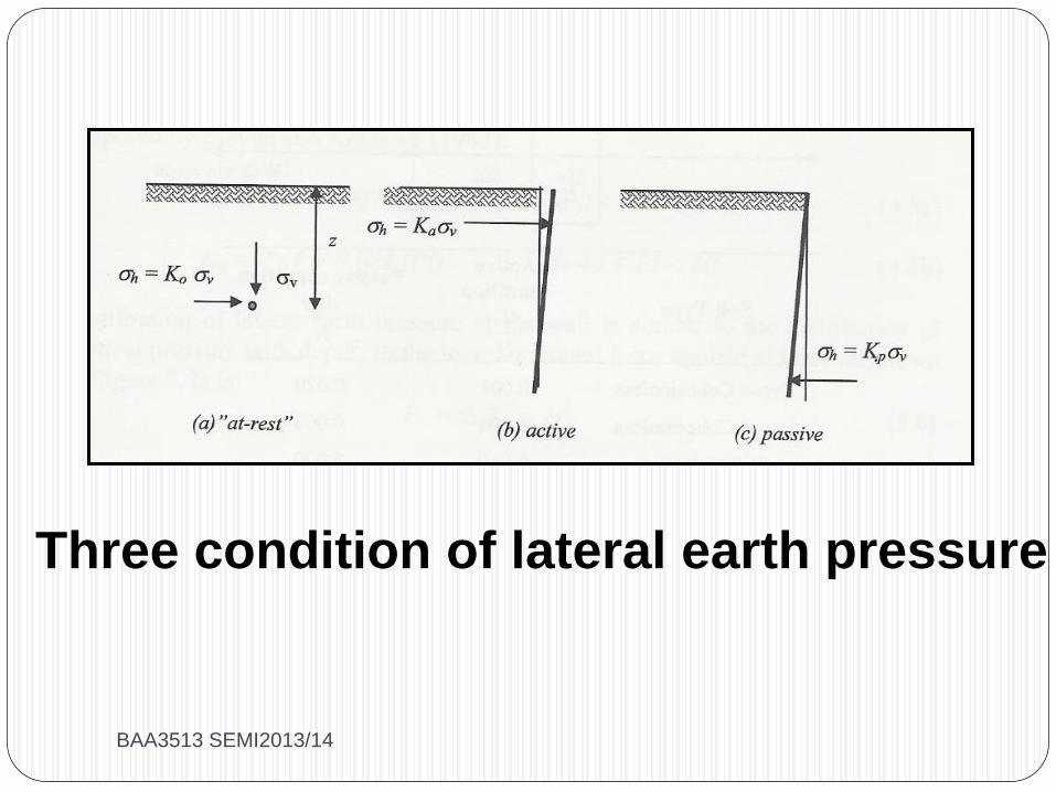
Three condition of lateral earth pressure
BAA3513 SEMI2013/14
At rest pressure
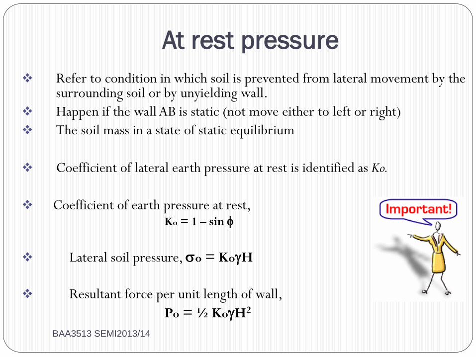
Refer to condition in which soil is prevented from lateral movement by the surrounding soil or by unyielding wall.
Happen if the wall AB is static (not move either to left or right)
The soil mass in a state of static equilibrium
Coefficient of lateral earth pressure at rest is identified as Ko.
Coefficient of earth pressure at rest, Ko = 1 – sin
Lateral soil pressure, o = KoH
Resultant force per unit length of wall,
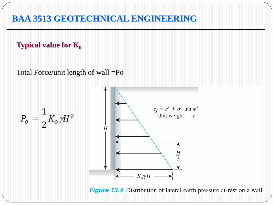
Po = ½ KoH2
BAA3513 SEMI2013/14
BAA 3513 GEOTECHNICAL ENGINEERING
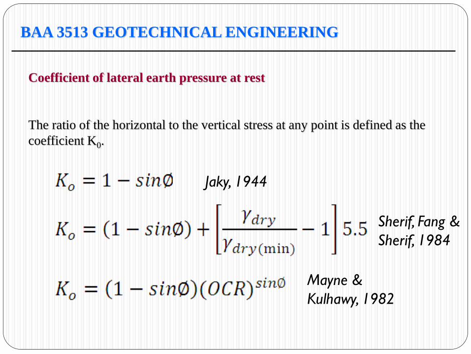
Coefficient of lateral earth pressure at rest
The ratio of the horizontal to the vertical stress at any point is defined as the
coefficient K0.
Jaky, 1944
Sherif, Fang &
Sherif, 1984
Mayne &
Kulhawy, 1982
BAA 3513 GEOTECHNICAL ENGINEERING
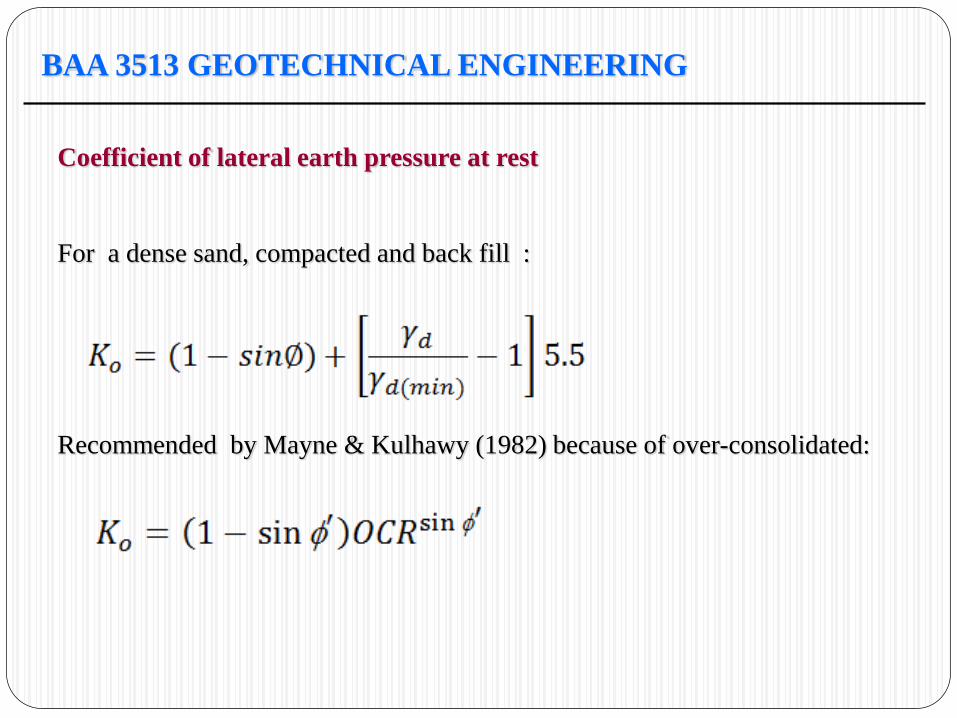
Coefficient of lateral earth pressure at rest
For a dense sand, compacted and back fill :
Recommended by Mayne & Kulhawy (1982) because of over-consolidated:
BAA 3513 GEOTECHNICAL ENGINEERING
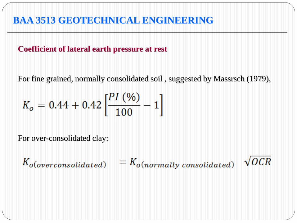
Coefficient of lateral earth pressure at rest
For fine grained, normally consolidated soil , suggested by Massrsch (1979),
For over-consolidated clay:
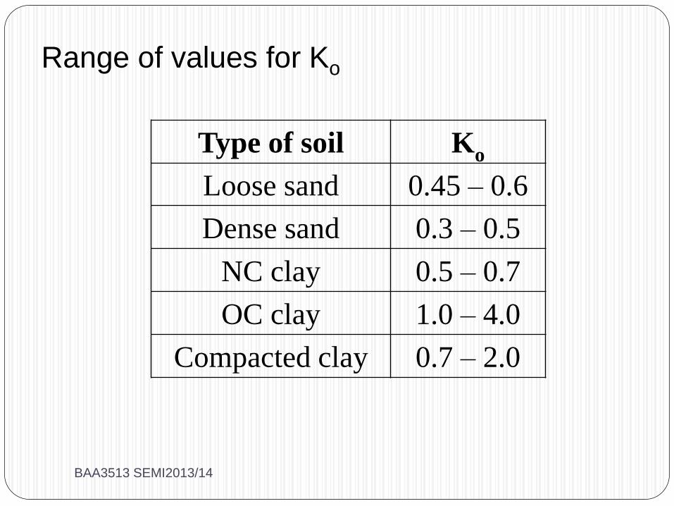
Type of soil Ko
Loose sand 0.45 – 0.6
Dense sand 0.3 – 0.5
NC clay 0.5 – 0.7
OC clay 1.0 – 4.0
Compacted clay 0.7 – 2.0
Range of values for Ko
BAA3513 SEMI2013/14
BAA 3513 GEOTECHNICAL ENGINEERING
Typical value for K0
Total Force/unit length of wall =Po
BAA 3513 GEOTECHNICAL ENGINEERING
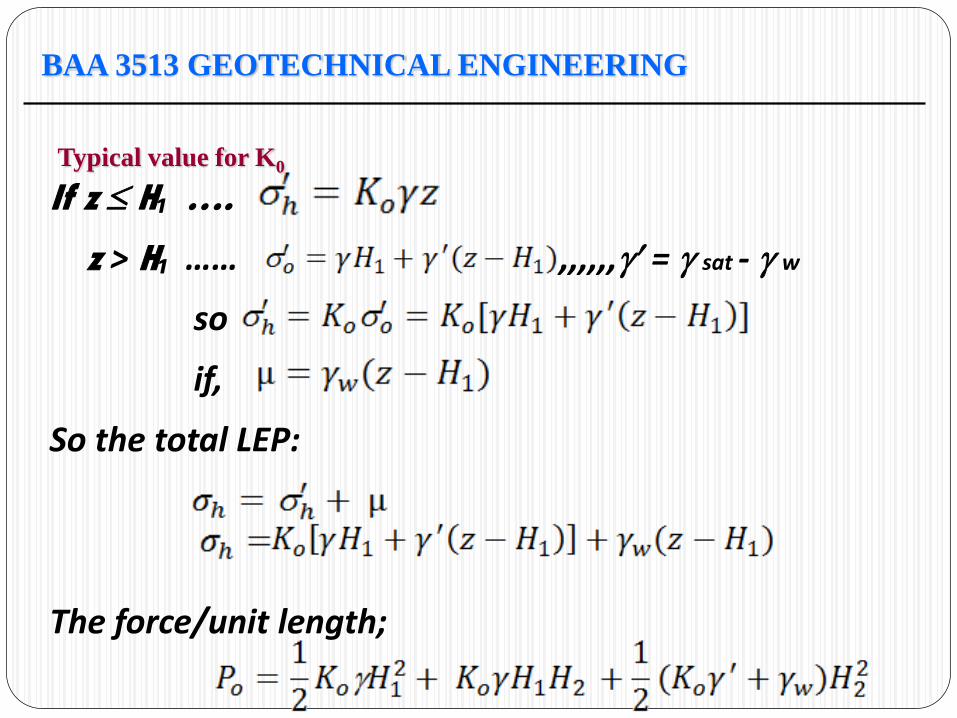
Typical value for K0
If z H₁ ….
z > H₁ …… ,,,,,, = sat - w
so
if,
So the total LEP:
The force/unit length;
BAA 3513 GEOTECHNICAL ENGINEERING
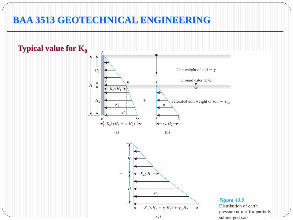
Typical value for K0
At rest Lateral earth
pressures
Let’s try examples given…
BAA3513 SEMI2013/14
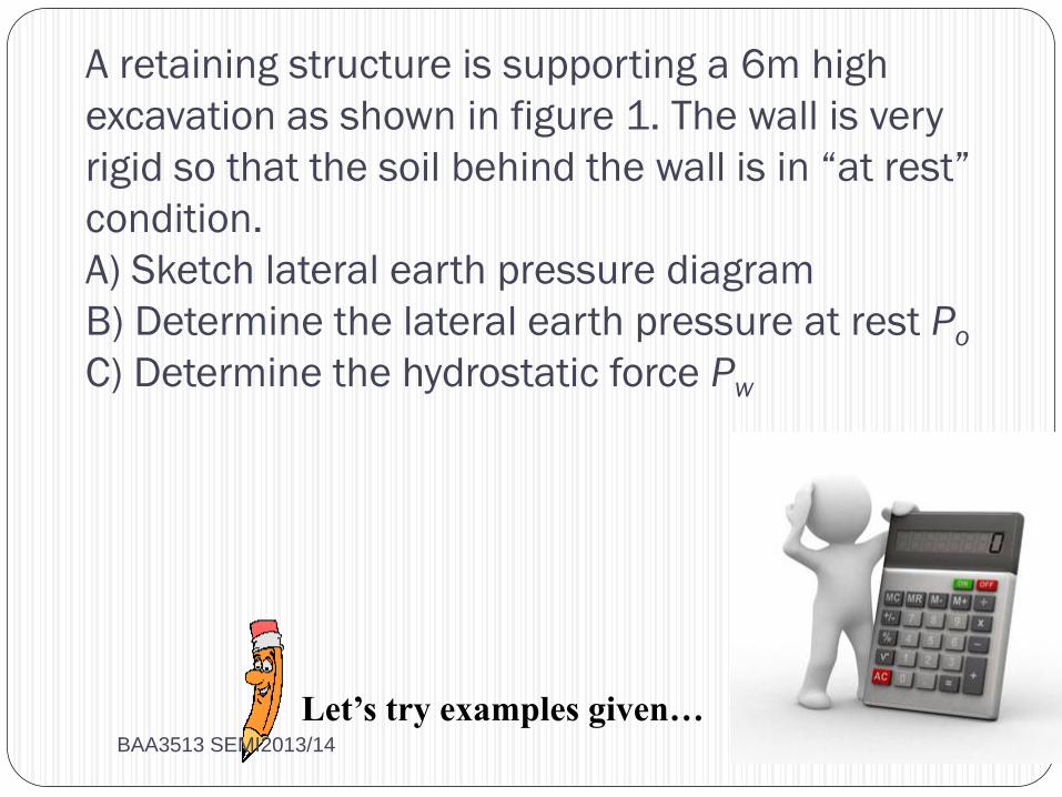
A retaining structure is supporting a 6m high
excavation as shown in figure 1. The wall is very
rigid so that the soil behind the wall is in “at rest”
condition.
A) Sketch lateral earth pressure diagram
B) Determine the lateral earth pressure at rest Po
C) Determine the hydrostatic force Pw
Let’s try examples given… BAA3513 SEMI2013/14
DAA3513 GEOTECHNICAL ENGINEERING
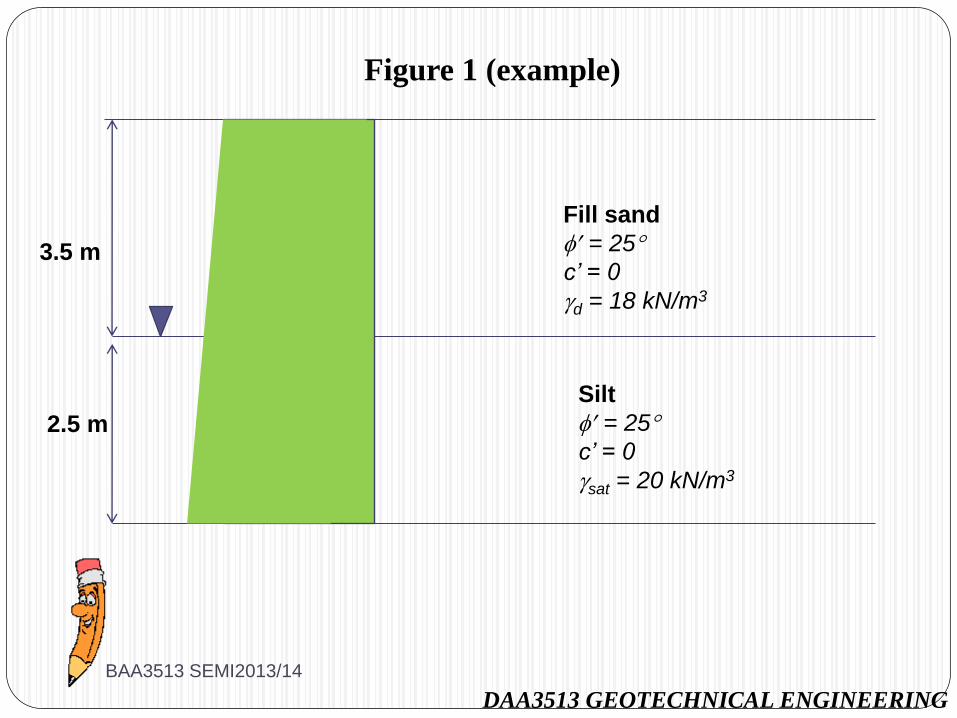
Figure 1 (example)
3.5 m
2.5 m
Fill sand
= 25
c’ = 0
d = 18 kN/m3
Silt
= 25
c’ = 0
sat = 20 kN/m3
BAA3513 SEMI2013/14
Active lateral earth pressure
Happen if the wall moves away from the soil
The soil tend to experienced shear failure which resulted a sliding soil wedge that move forward and downward
The earth pressure exerted on the wall at this state of failure is known as active earth pressure, Pa
There are several method that can be use to calculate the active / passive lateral earth pressure
i) Rankine’s approach
ii) Coulomb’s approach
iii) Culmann’s method
BAA3513 SEMI2013/14
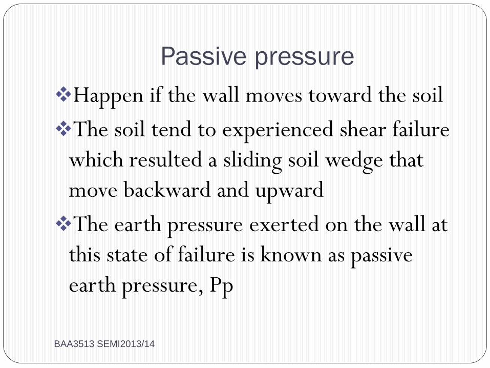
Passive pressure
Happen if the wall moves toward the soil
The soil tend to experienced shear failure
which resulted a sliding soil wedge that
move backward and upward
The earth pressure exerted on the wall at
this state of failure is known as passive
earth pressure, Pp
BAA3513 SEMI2013/14
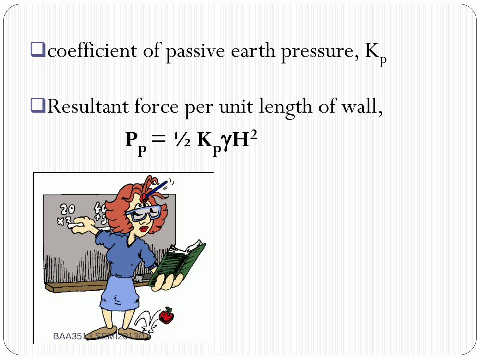
coefficient of passive earth pressure, Kp
Resultant force per unit length of wall,
Pp = ½ KpH2
BAA3513 SEMI2013/14
BAA 3513 GEOTECHNICAL ENGINEERING
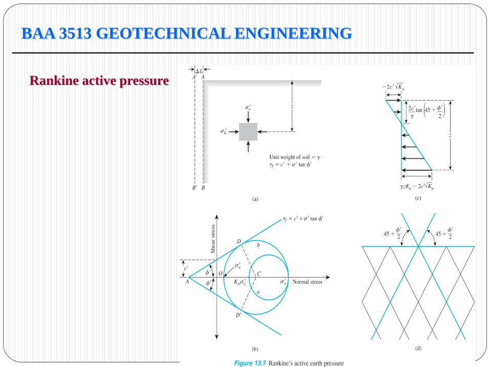
Rankine active pressure
BAA 3513 GEOTECHNICAL ENGINEERING
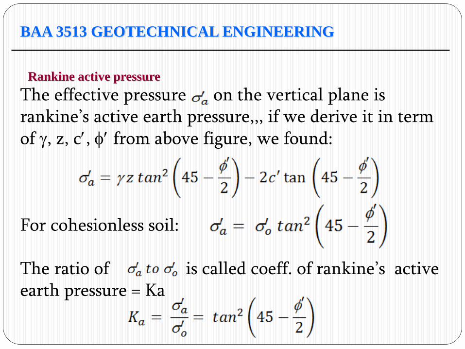
Rankine active pressure
The effective pressure on the vertical plane is rankine’s active earth pressure,,, if we derive it in term of , z, c, from above figure, we found: For cohesionless soil: The ratio of is called coeff. of rankine’s active earth pressure = Ka
BAA 3513 GEOTECHNICAL ENGINEERING
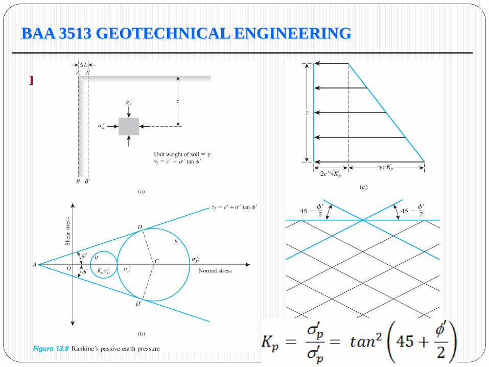
Rankine passive pressure
BAA 3513 GEOTECHNICAL ENGINEERING
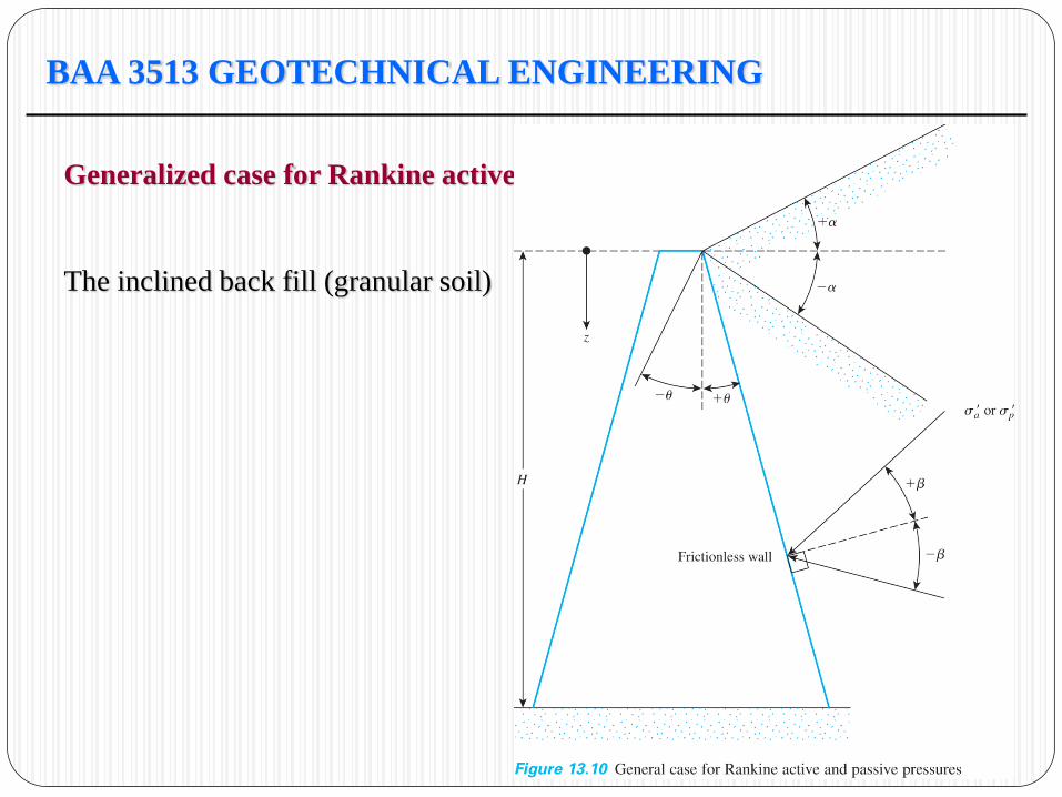
Generalized case for Rankine active/passive pressure
The inclined back fill (granular soil)
BAA 3513 GEOTECHNICAL ENGINEERING
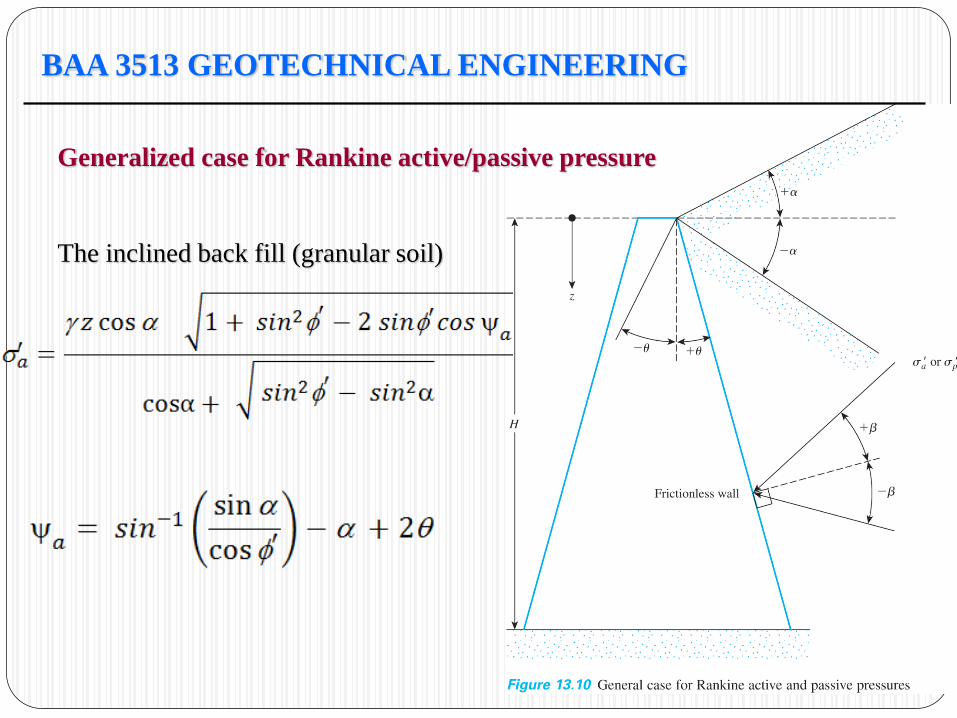
Generalized case for Rankine active/passive pressure
The inclined back fill (granular soil)
BAA 3513 GEOTECHNICAL ENGINEERING
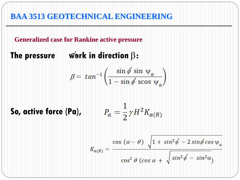
Generalized case for Rankine active pressure
The pressure work in direction :
So, active force (Pa),

BAA 3513 GEOTECHNICAL ENGINEERING
Generalized case for Rankine active pressure
The location & direction of resultant Pa is shown
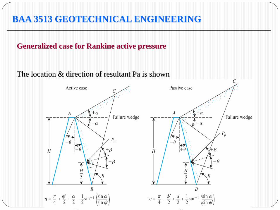
BAA 3513 GEOTECHNICAL ENGINEERING
Generalized case for Rankine active pressure
The location & direction of resultant Pa is shown
BAA 3513 GEOTECHNICAL ENGINEERING
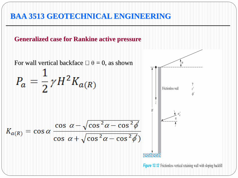
Generalized case for Rankine active pressure
For wall vertical backface = 0, as shown
BAA 3513 GEOTECHNICAL ENGINEERING
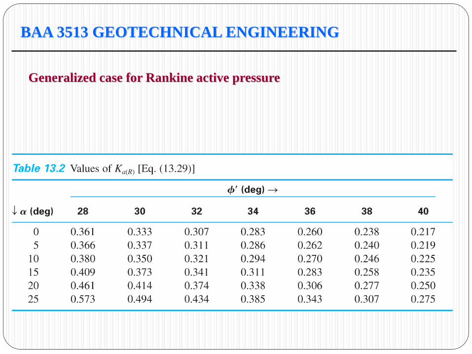
Generalized case for Rankine active pressure
BAA 3513 GEOTECHNICAL ENGINEERING
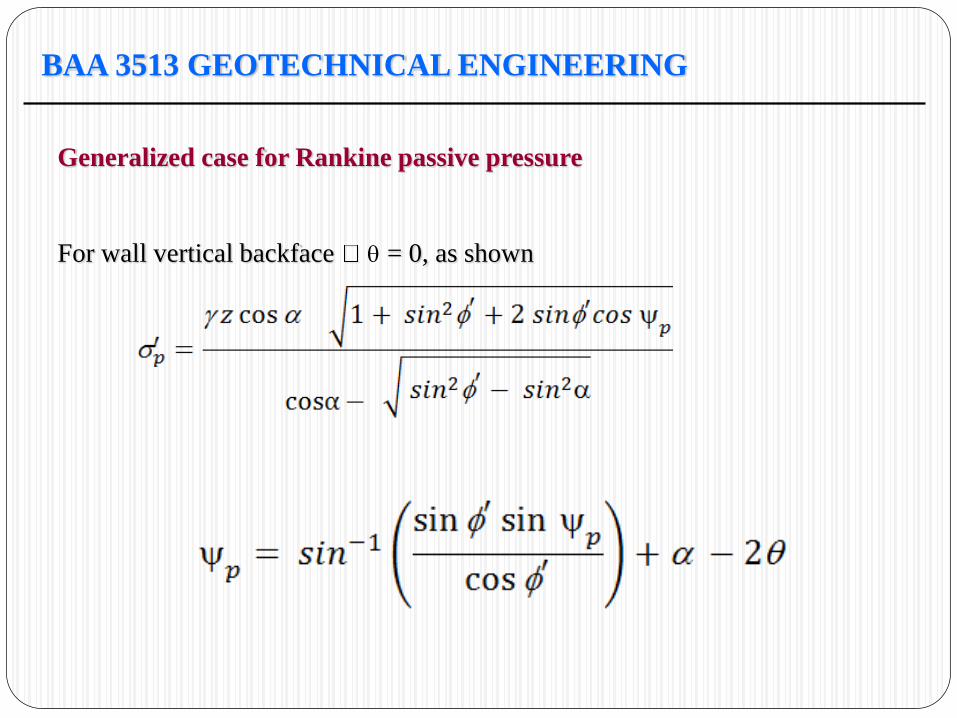
Generalized case for Rankine passive pressure
For wall vertical backface = 0, as shown
BAA 3513 GEOTECHNICAL ENGINEERING
Generalized case for Rankine passive pressure
BAA 3513 GEOTECHNICAL ENGINEERING
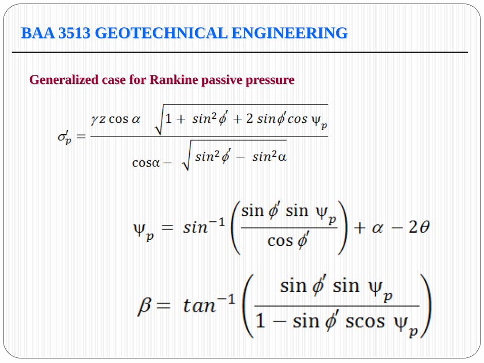
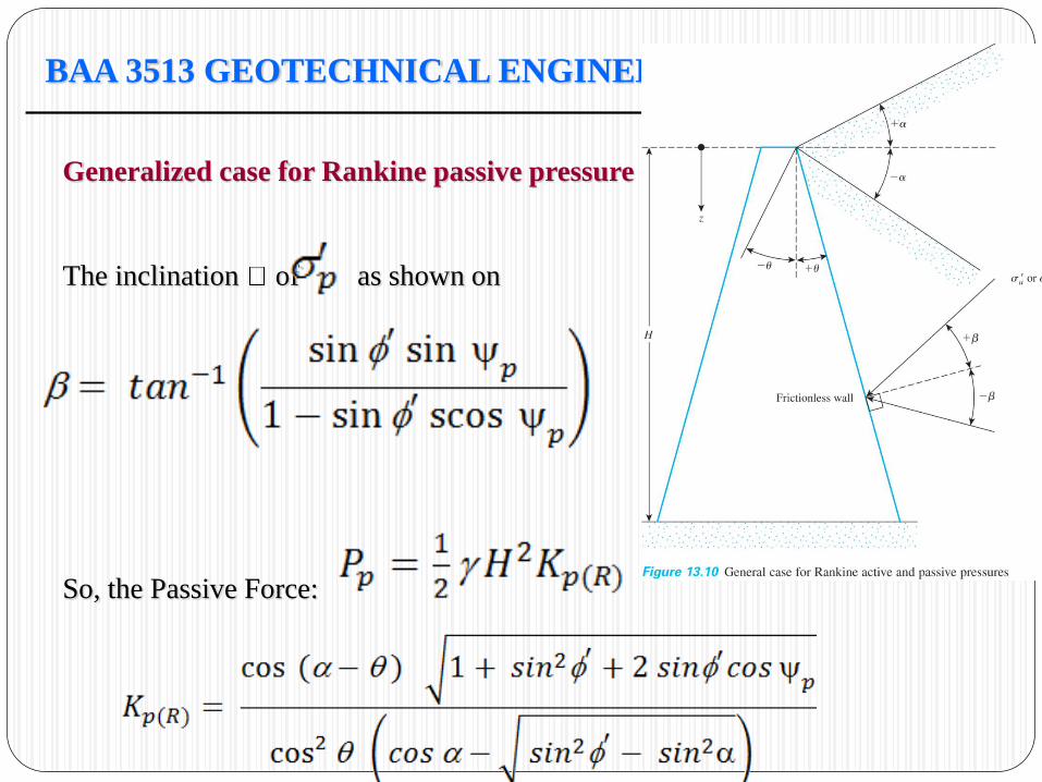
Generalized case for Rankine passive pressure
The inclination of as shown on
So, the Passive Force:
BAA 3513 GEOTECHNICAL ENGINEERING
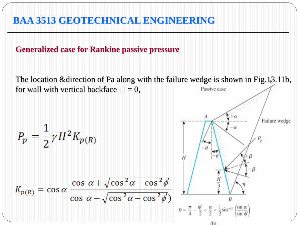
Generalized case for Rankine passive pressure
The location &direction of Pa along with the failure wedge is shown in Fig.13.11b,
for wall with vertical backface = 0,
BAA 3513 GEOTECHNICAL ENGINEERING
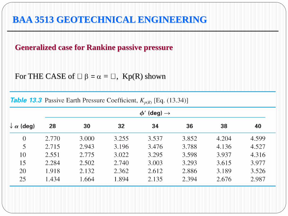
Generalized case for Rankine passive pressure
For THE CASE of = = , Kp(R) shown
BAA 3513 GEOTECHNICAL ENGINEERING
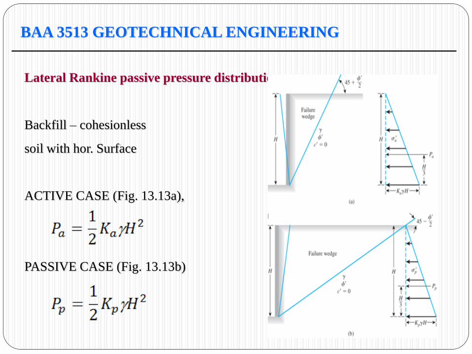
Lateral Rankine passive pressure distribution
Backfill – cohesionless
soil with hor. Surface
ACTIVE CASE (Fig. 13.13a),
PASSIVE CASE (Fig. 13.13b)
BAA 3513 GEOTECHNICAL ENGINEERING
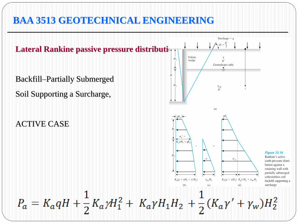
Lateral Rankine passive pressure distribution
Backfill–Partially Submerged
Soil Supporting a Surcharge,
ACTIVE CASE
BAA 3513 GEOTECHNICAL ENGINEERING
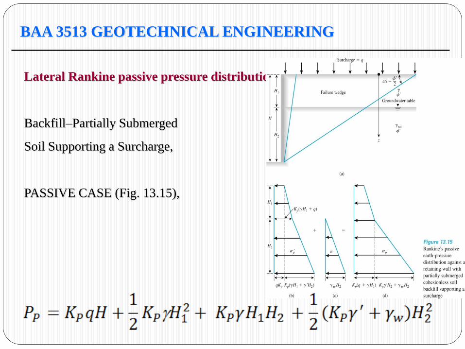
Lateral Rankine passive pressure distribution
Backfill–Partially Submerged
Soil Supporting a Surcharge,
PASSIVE CASE (Fig. 13.15),
BAA 3513 GEOTECHNICAL ENGINEERING
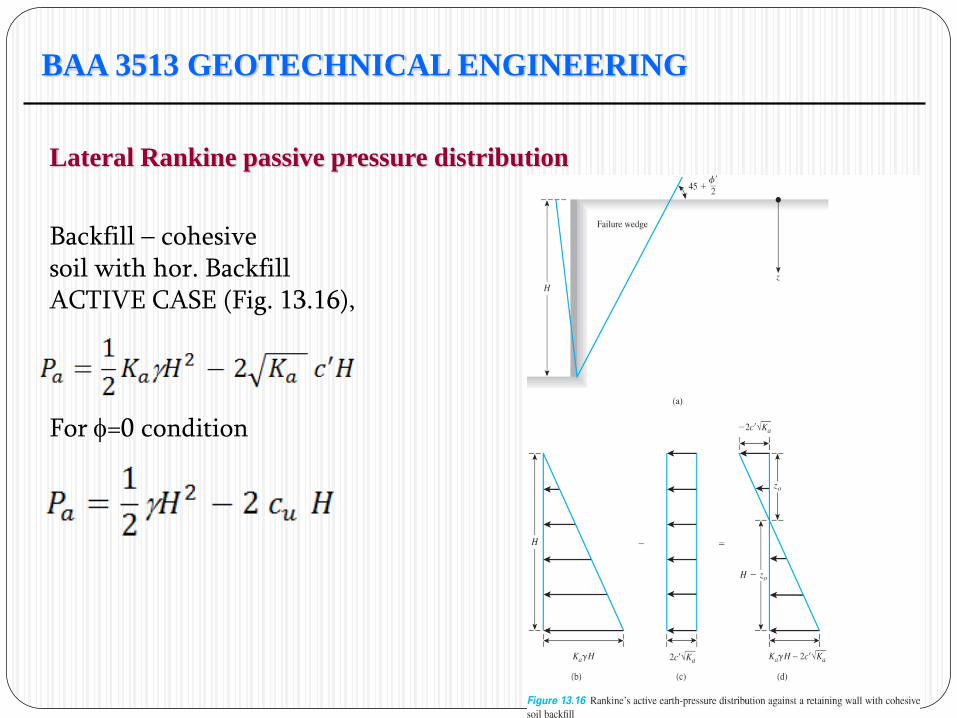
Lateral Rankine passive pressure distribution
Backfill – cohesive soil with hor. Backfill ACTIVE CASE (Fig. 13.16), For =0 condition
BAA 3513 GEOTECHNICAL ENGINEERING
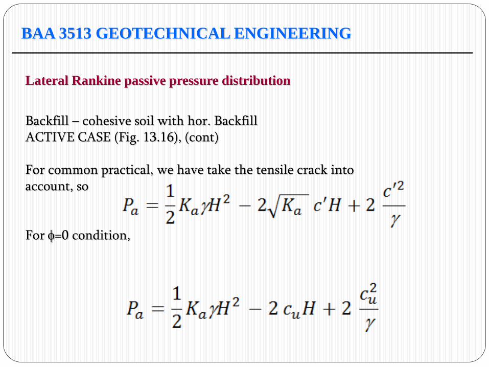
Lateral Rankine passive pressure distribution
Backfill – cohesive soil with hor. Backfill ACTIVE CASE (Fig. 13.16), (cont) For common practical, we have take the tensile crack into account, so For =0 condition,
BAA 3513 GEOTECHNICAL ENGINEERING
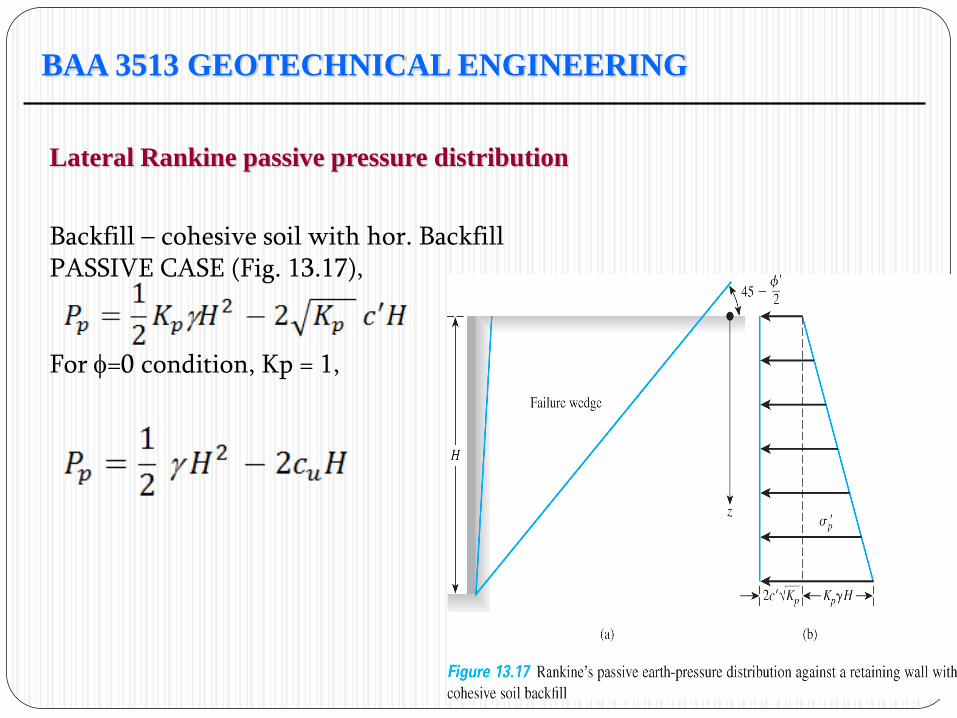
Lateral Rankine passive pressure distribution
Backfill – cohesive soil with hor. Backfill PASSIVE CASE (Fig. 13.17), For =0 condition, Kp = 1,
BAA 3513 GEOTECHNICAL ENGINEERING
Lateral Rankine passive pressure distribution
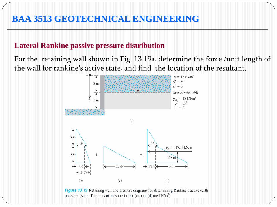
For the retaining wall shown in Fig. 13.19a, determine the force /unit length of the wall for rankine’s active state, and find the location of the resultant.
BAA 3513 GEOTECHNICAL ENGINEERING
Lateral Rankine passive pressure distribution
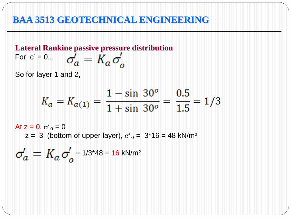
For c = 0,,,
So for layer 1 and 2,
At z = 0, ₀ = 0
z = 3 (bottom of upper layer), ₀ = 3*16 = 48 kN/m²
= 1/3*48 = 16 kN/m²
BAA 3513 GEOTECHNICAL ENGINEERING
Lateral Rankine passive pressure distribution
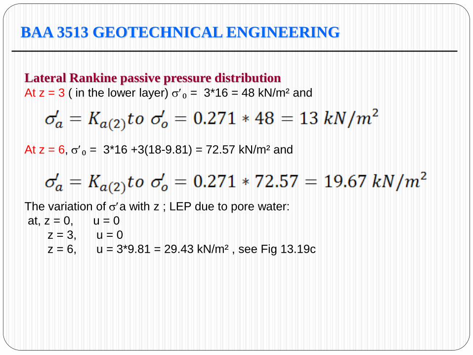
At z = 3 ( in the lower layer) ₀ = 3*16 = 48 kN/m² and
At z = 6, ₀ = 3*16 +3(18-9.81) = 72.57 kN/m² and
The variation of a with z ; LEP due to pore water:
at, z = 0, u = 0
z = 3, u = 0
z = 6, u = 3*9.81 = 29.43 kN/m² , see Fig 13.19c
BAA 3513 GEOTECHNICAL ENGINEERING
Lateral Rankine passive pressure distribution
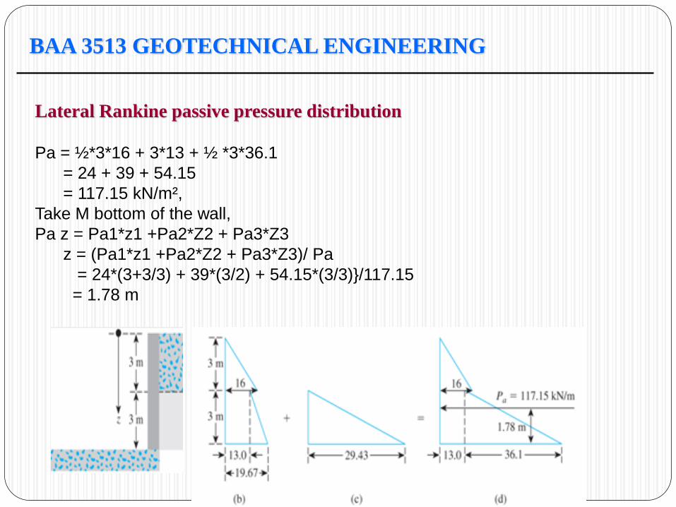
Pa = ½*3*16 + 3*13 + ½ *3*36.1
= 24 + 39 + 54.15
= 117.15 kN/m²,
Take M bottom of the wall,
Pa z = Pa1*z1 +Pa2*Z2 + Pa3*Z3
z = (Pa1*z1 +Pa2*Z2 + Pa3*Z3)/ Pa
= 24*(3+3/3) + 39*(3/2) + 54.15*(3/3)}/117.15
= 1.78 m
BAA 3513 GEOTECHNICAL ENGINEERING
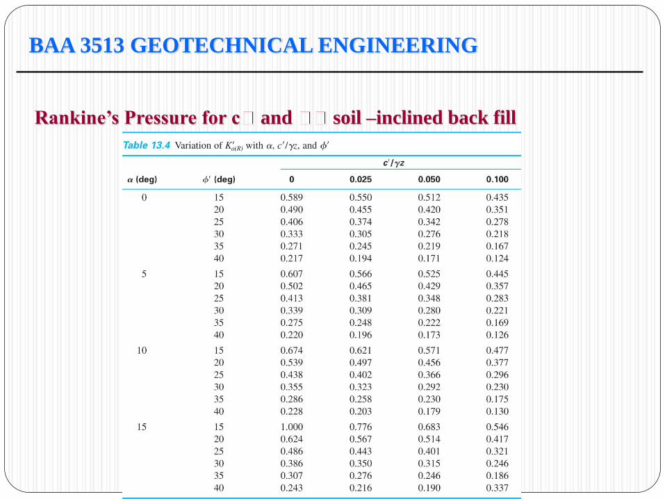
Rankine’s Pressure for c and soil –inclined back fill
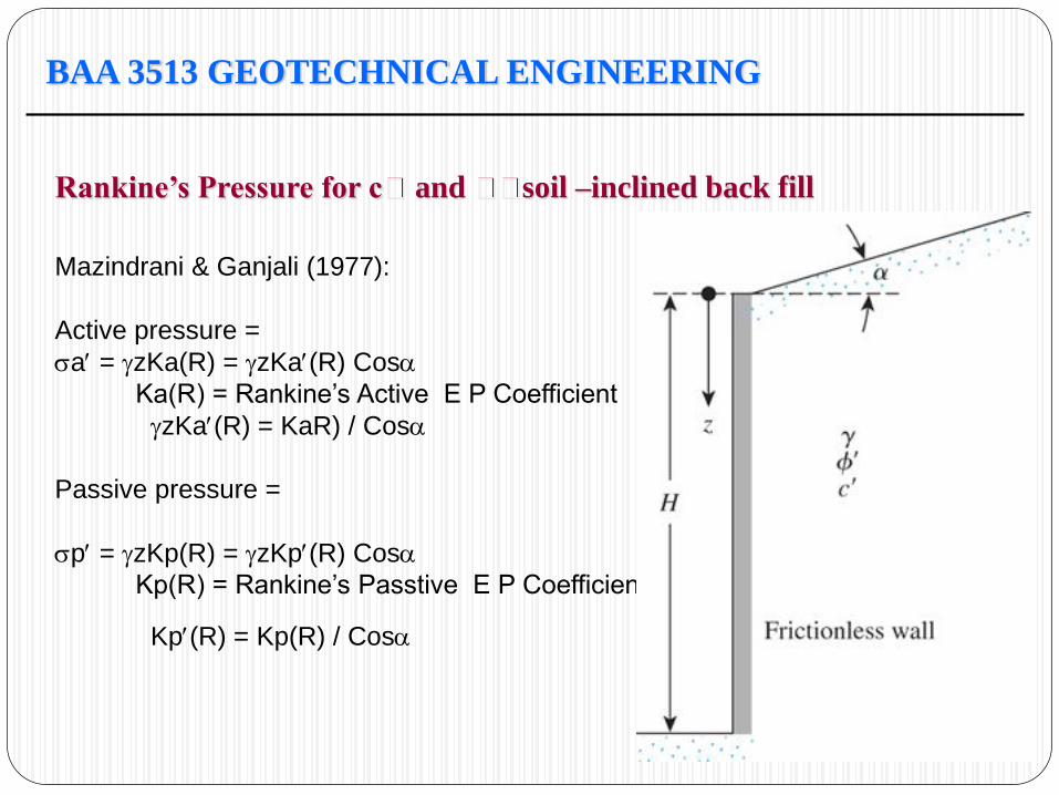
Mazindrani & Ganjali (1977):
Active pressure =
a = zKa(R) = zKa(R) Cos
Ka(R) = Rankine’s Active E P Coefficient
zKa(R) = KaR) / Cos
Passive pressure =
p = zKp(R) = zKp(R) Cos
Kp(R) = Rankine’s Passtive E P Coefficient
Kp(R) = Kp(R) / Cos
BAA 3513 GEOTECHNICAL ENGINEERING
Rankine’s Pressure for c and soil –inclined back fill
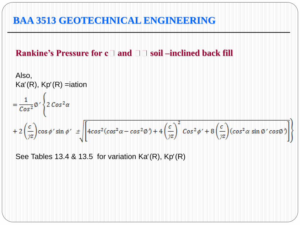
Also,
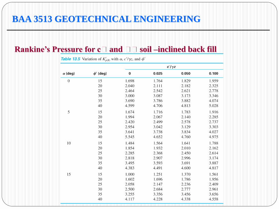
Ka(R), Kp(R) =iation
See Tables 13.4 & 13.5 for variation Ka(R), Kp(R)
BAA 3513 GEOTECHNICAL ENGINEERING
Rankine’s Pressure for c and soil –inclined back fill
BAA 3513 GEOTECHNICAL ENGINEERING
Rankine’s Pressure for c and soil –inclined back fill
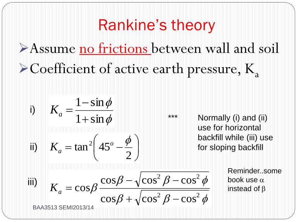
Rankine’s theory
Assume no frictions between wall and soil
Coefficient of active earth pressure, Ka
245tan2 o
aK
sin1
sin1
aK
22
22
coscoscos
coscoscoscos
aK
Reminder..some
book use
instead of
*** Normally (i) and (ii)
use for horizontal
backfill while (iii) use
for sloping backfill ii)
i)
iii)
BAA3513 SEMI2013/14
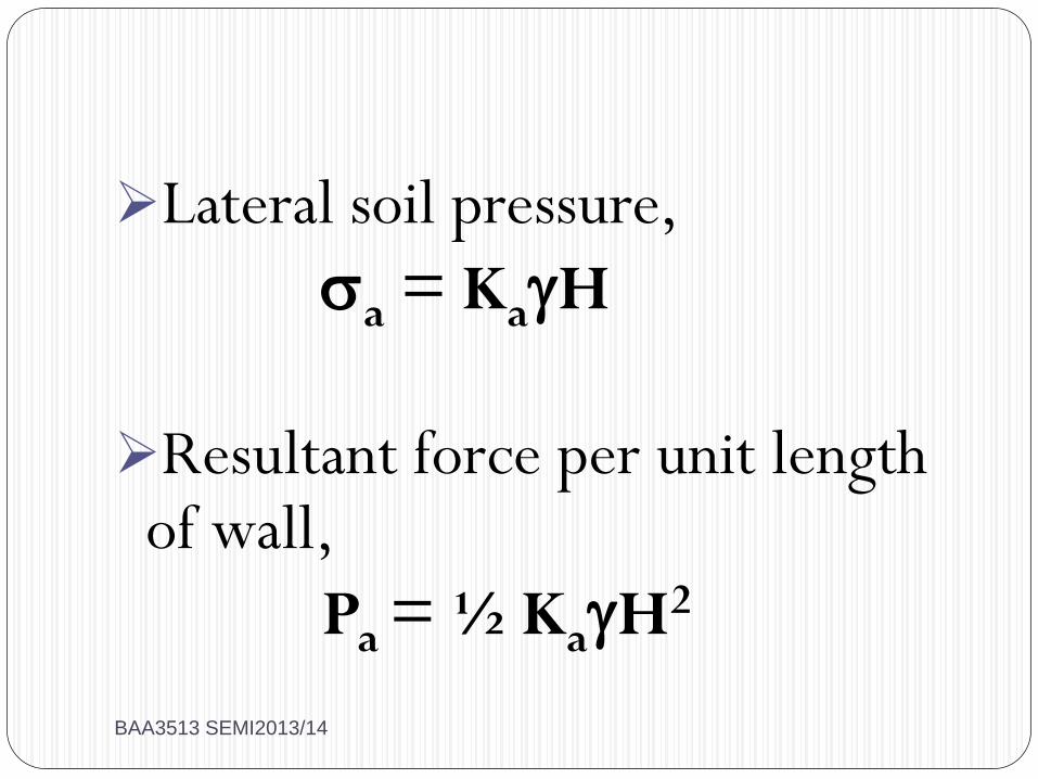
Lateral soil pressure,
a = KaH
Resultant force per unit length of wall,
Pa = ½ KaH2
BAA3513 SEMI2013/14
William J.M. Rankine
BAA3513 SEMI2013/14
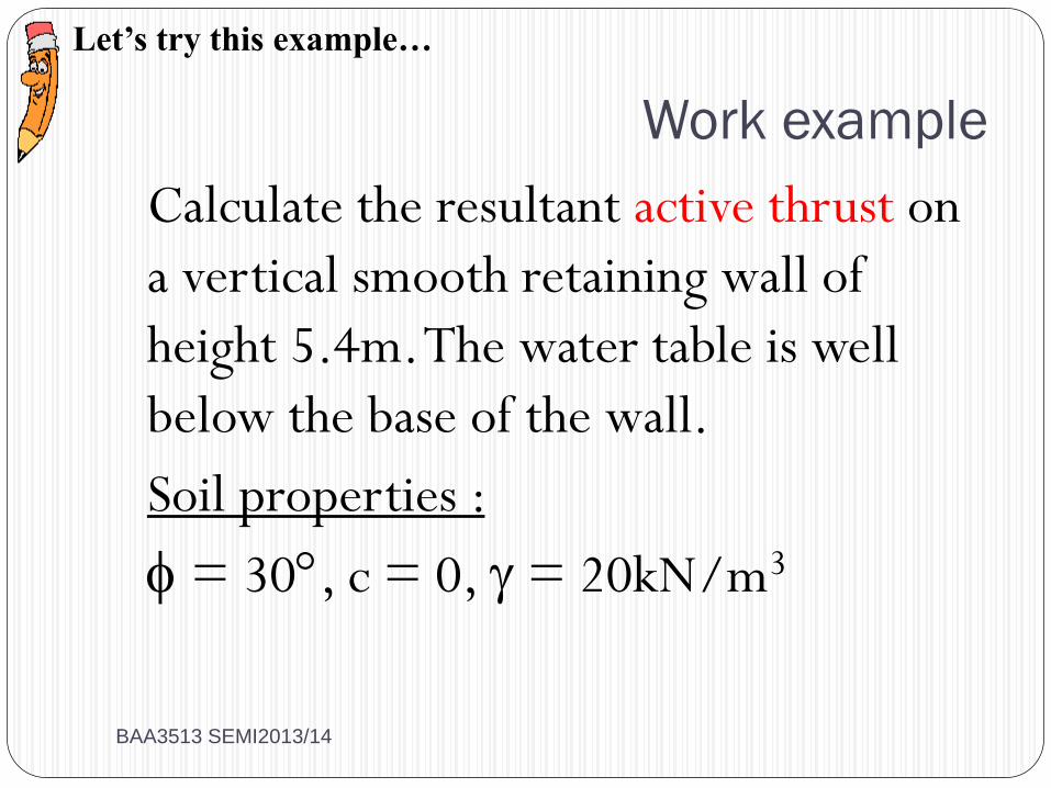
Work example
Calculate the resultant active thrust on
a vertical smooth retaining wall of
height 5.4m. The water table is well
below the base of the wall.
Soil properties :
= 30, c = 0, = 20kN/m3
Let’s try this example…
BAA3513 SEMI2013/14
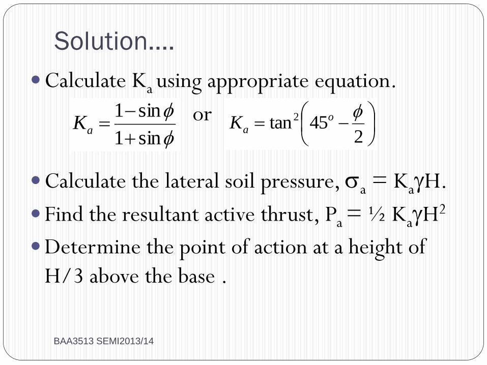
Solution….
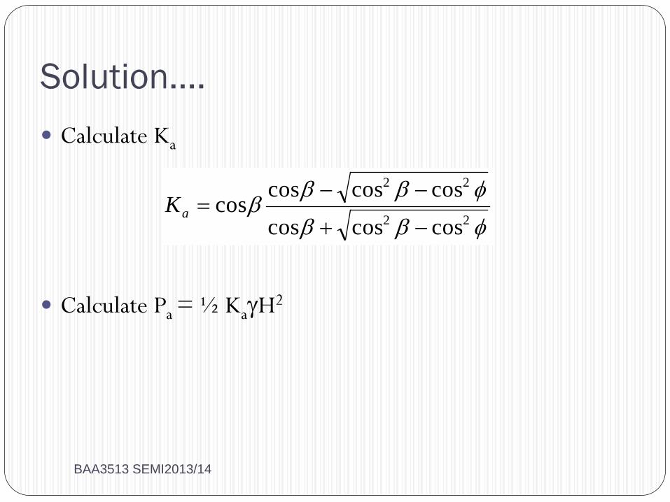
Calculate Ka using appropriate equation.
or
Calculate the lateral soil pressure, a = KaH.
Find the resultant active thrust, Pa = ½ KaH2
Determine the point of action at a height of
H/3 above the base .
245tan2 o
aK
sin1
sin1
aK
BAA3513 SEMI2013/14
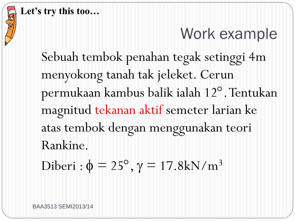
Work example
Sebuah tembok penahan tegak setinggi 4m
menyokong tanah tak jeleket. Cerun
permukaan kambus balik ialah 12. Tentukan
magnitud tekanan aktif semeter larian ke
atas tembok dengan menggunakan teori
Rankine.
Diberi : = 25, = 17.8kN/m3
Let’s try this too…
BAA3513 SEMI2013/14
Solution….
Calculate Ka
Calculate Pa = ½ KaH2
22
22
coscoscos
coscoscoscos
aK
BAA3513 SEMI2013/14
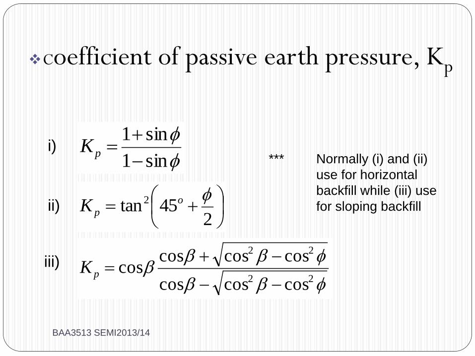
Coefficient of passive earth pressure, Kp
*** Normally (i) and (ii)
use for horizontal
backfill while (iii) use
for sloping backfill ii)
i)
iii)
245tan2 o
pK
sin1
sin1
pK
22
22
coscoscos
coscoscoscos
pK
BAA3513 SEMI2013/14
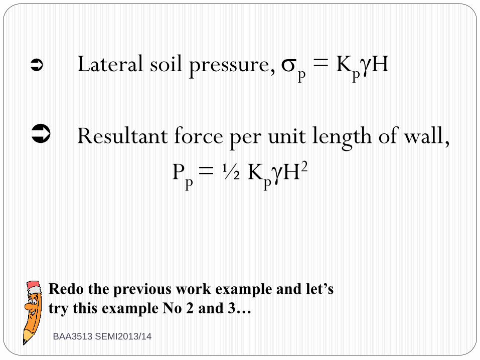
Lateral soil pressure, p = KpH
Resultant force per unit length of wall,
Pp = ½ KpH2
Redo the previous work example and let’s
try this example No 2 and 3…
BAA3513 SEMI2013/14
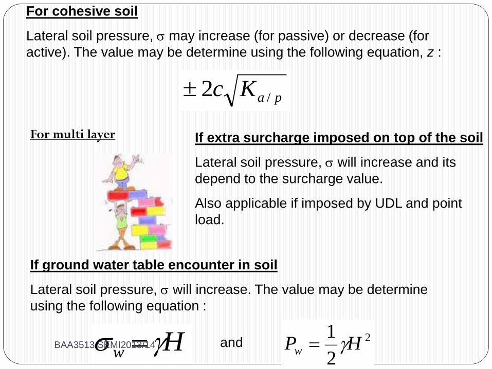
For multi layer
For cohesive soil
Lateral soil pressure, may increase (for passive) or decrease (for
active). The value may be determine using the following equation, z :
paKc /2
If ground water table encounter in soil
Lateral soil pressure, will increase. The value may be determine
using the following equation :
Hw 2
2
1HPw
and
If extra surcharge imposed on top of the soil
Lateral soil pressure, will increase and its
depend to the surcharge value.
Also applicable if imposed by UDL and point
load.
BAA3513 SEMI2013/14

BAA3513 SEMI2013/14
Let’s try more examples…
Don’t worry…
BAA3513 SEMI2013/14
BAA 3513 GEOTECHNICAL ENGINEERING
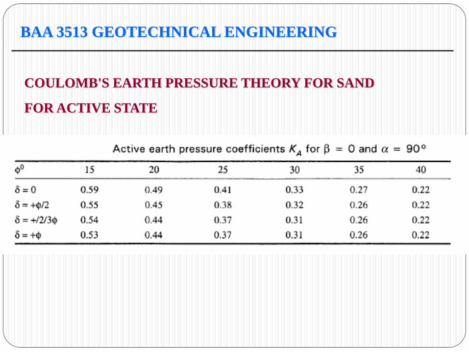
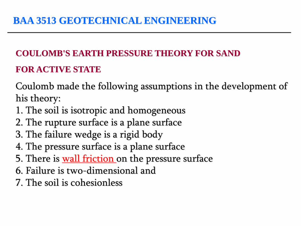
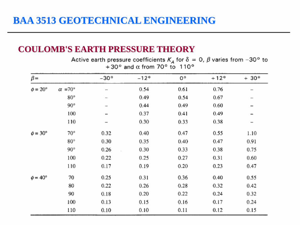
COULOMB'S EARTH PRESSURE THEORY FOR SAND
FOR ACTIVE STATE
Coulomb made the following assumptions in the development of his theory: 1. The soil is isotropic and homogeneous 2. The rupture surface is a plane surface 3. The failure wedge is a rigid body 4. The pressure surface is a plane surface 5. There is wall friction on the pressure surface 6. Failure is two-dimensional and 7. The soil is cohesionless
BAA 3513 GEOTECHNICAL ENGINEERING
COULOMB'S EARTH PRESSURE THEORY FOR SAND
FOR ACTIVE STATE
BAA 3513 GEOTECHNICAL ENGINEERING
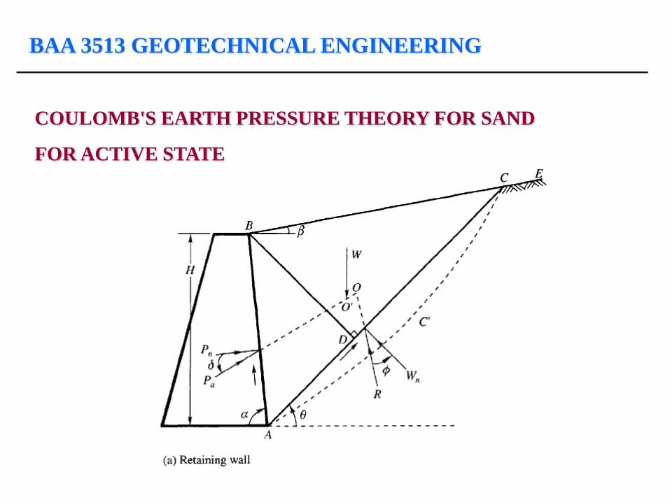
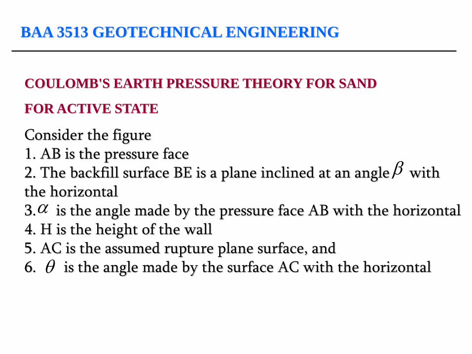
COULOMB'S EARTH PRESSURE THEORY FOR SAND
FOR ACTIVE STATE
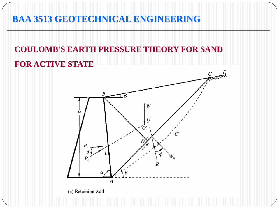
Consider the figure 1. AB is the pressure face 2. The backfill surface BE is a plane inclined at an angle with the horizontal 3. is the angle made by the pressure face AB with the horizontal 4. H is the height of the wall 5. AC is the assumed rupture plane surface, and 6. is the angle made by the surface AC with the horizontal
BAA 3513 GEOTECHNICAL ENGINEERING
COULOMB'S EARTH PRESSURE THEORY FOR SAND
FOR ACTIVE STATE
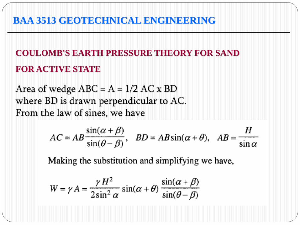
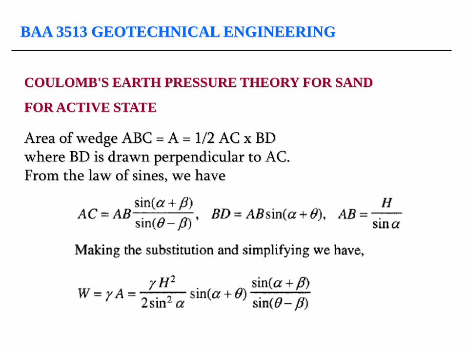
Area of wedge ABC = A = 1/2 AC x BD where BD is drawn perpendicular to AC. From the law of sines, we have
BAA 3513 GEOTECHNICAL ENGINEERING
COULOMB'S EARTH PRESSURE THEORY FOR SAND
FOR ACTIVE STATE
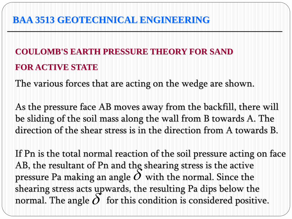
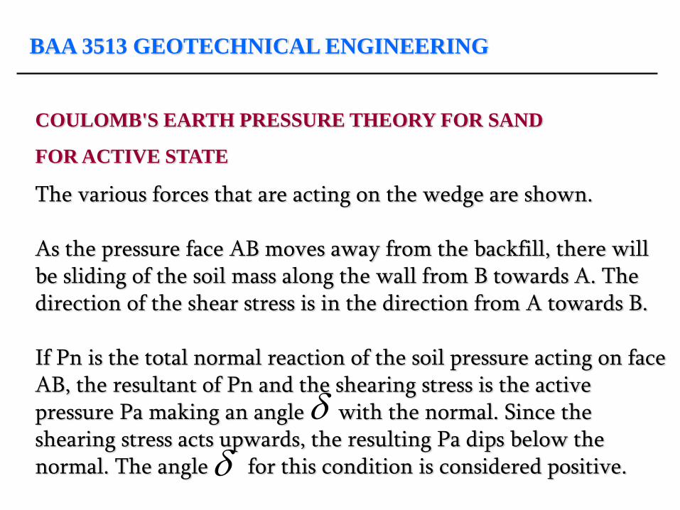
The various forces that are acting on the wedge are shown. As the pressure face AB moves away from the backfill, there will be sliding of the soil mass along the wall from B towards A. The direction of the shear stress is in the direction from A towards B. If Pn is the total normal reaction of the soil pressure acting on face AB, the resultant of Pn and the shearing stress is the active pressure Pa making an angle with the normal. Since the shearing stress acts upwards, the resulting Pa dips below the normal. The angle for this condition is considered positive.
BAA 3513 GEOTECHNICAL ENGINEERING
COULOMB'S EARTH PRESSURE THEORY FOR SAND
FOR ACTIVE STATE
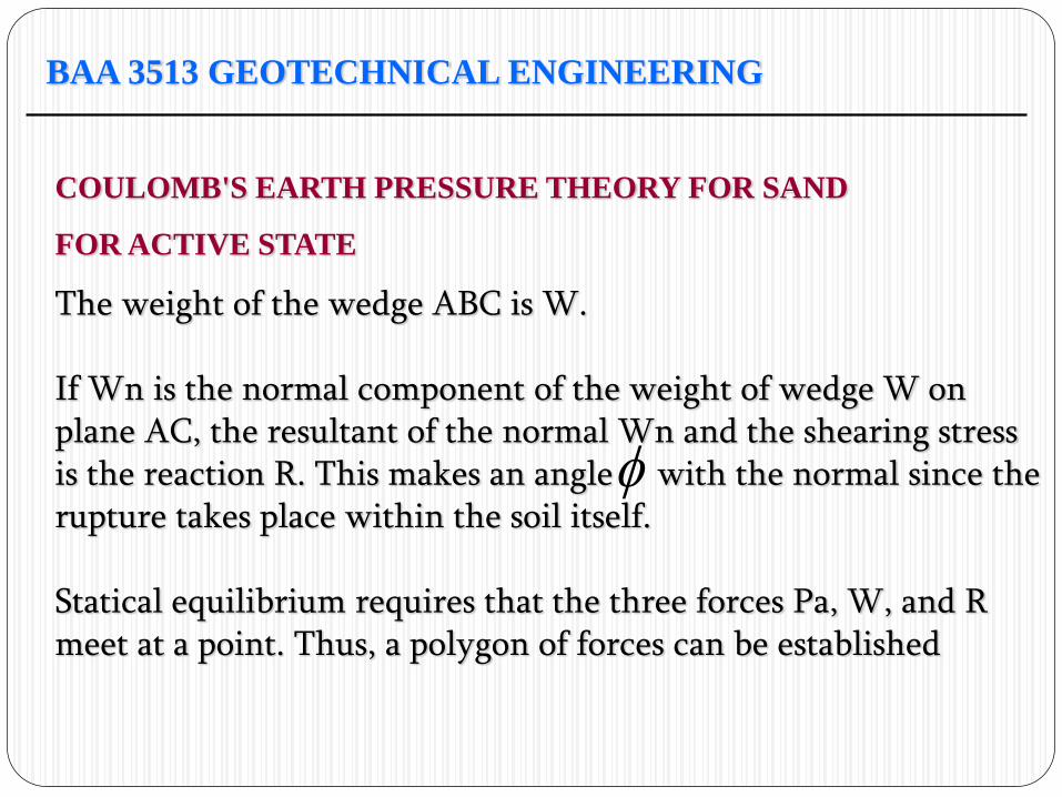
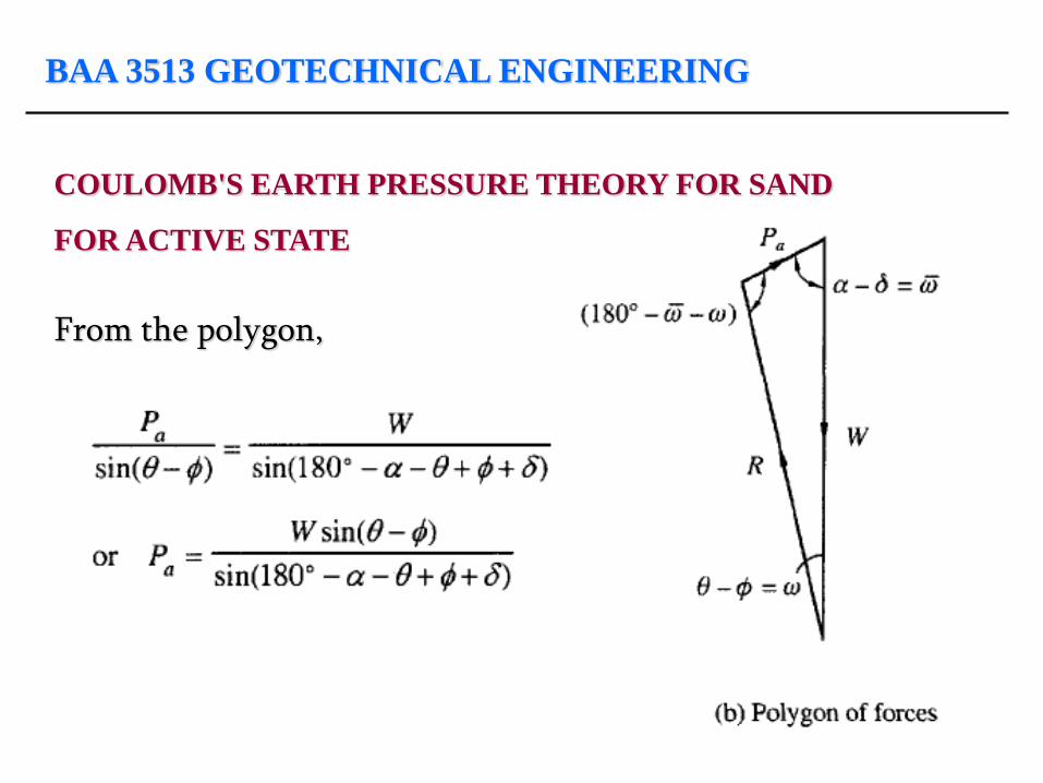
The weight of the wedge ABC is W. If Wn is the normal component of the weight of wedge W on plane AC, the resultant of the normal Wn and the shearing stress is the reaction R. This makes an angle with the normal since the rupture takes place within the soil itself. Statical equilibrium requires that the three forces Pa, W, and R meet at a point. Thus, a polygon of forces can be established

BAA 3513 GEOTECHNICAL ENGINEERING
COULOMB'S EARTH PRESSURE THEORY FOR SAND
FOR ACTIVE STATE
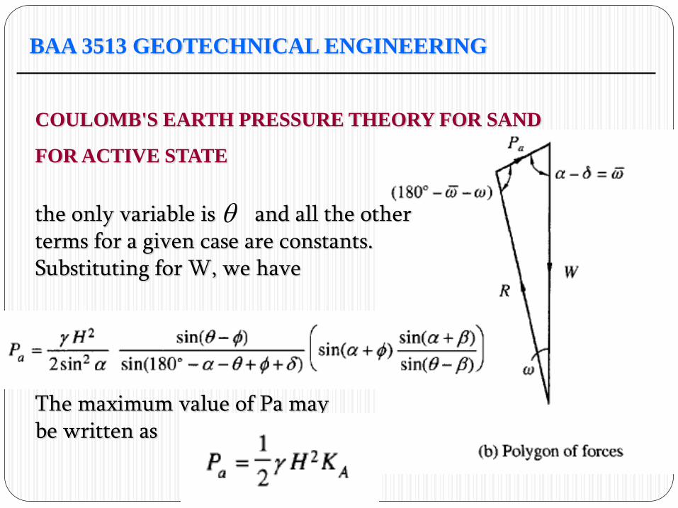
From the polygon,
BAA 3513 GEOTECHNICAL ENGINEERING
COULOMB'S EARTH PRESSURE THEORY FOR SAND
FOR ACTIVE STATE
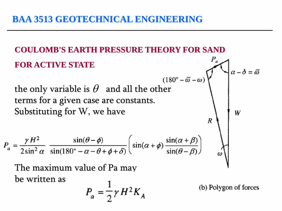
the only variable is and all the other terms for a given case are constants. Substituting for W, we have The maximum value of Pa may be written as
BAA 3513 GEOTECHNICAL ENGINEERING
COULOMB'S EARTH PRESSURE THEORY FOR SAND
FOR ACTIVE STATE
BAA 3513 GEOTECHNICAL ENGINEERING
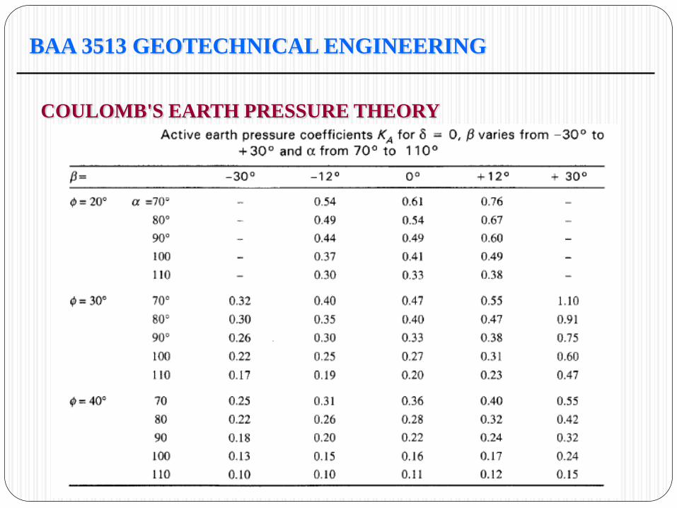
COULOMB'S EARTH PRESSURE THEORY
BAA 3513 GEOTECHNICAL ENGINEERING
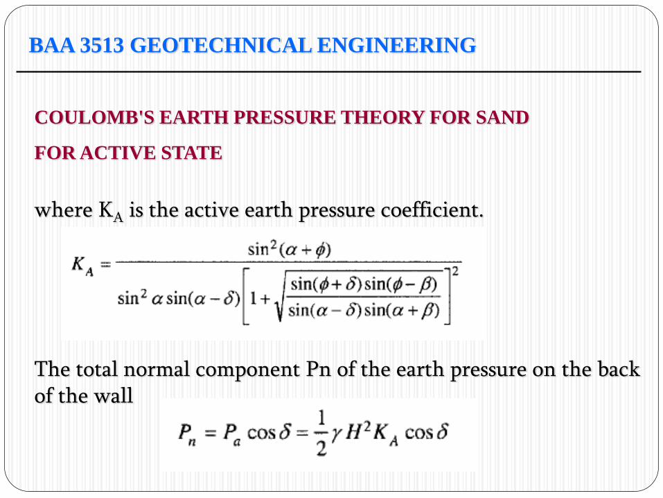
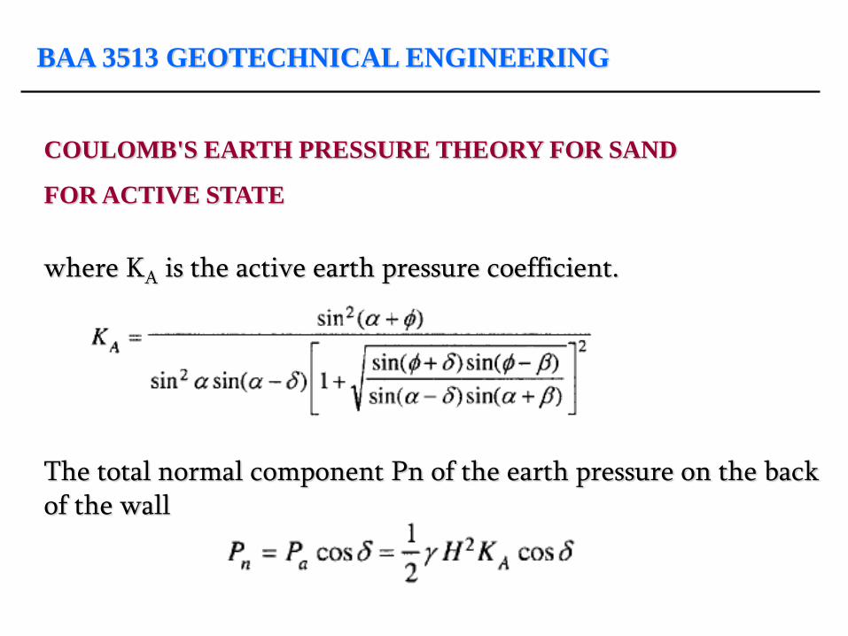
COULOMB'S EARTH PRESSURE THEORY FOR SAND
FOR ACTIVE STATE
where KA is the active earth pressure coefficient. The total normal component Pn of the earth pressure on the back of the wall
BAA 3513 GEOTECHNICAL ENGINEERING
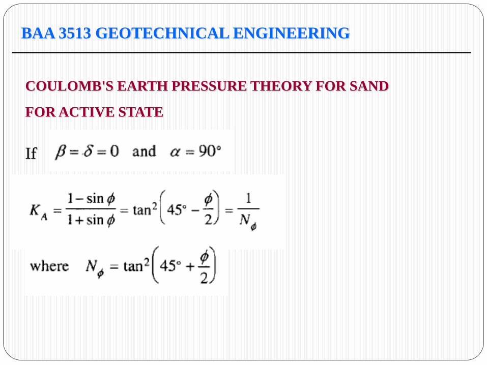
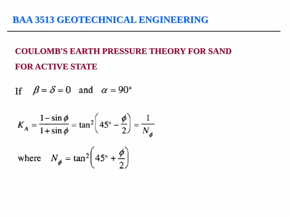
COULOMB'S EARTH PRESSURE THEORY FOR SAND
FOR ACTIVE STATE
If
BAA 3513 GEOTECHNICAL ENGINEERING
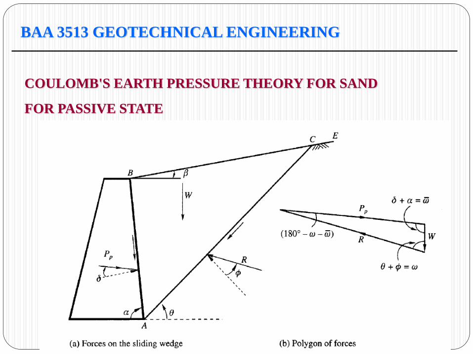
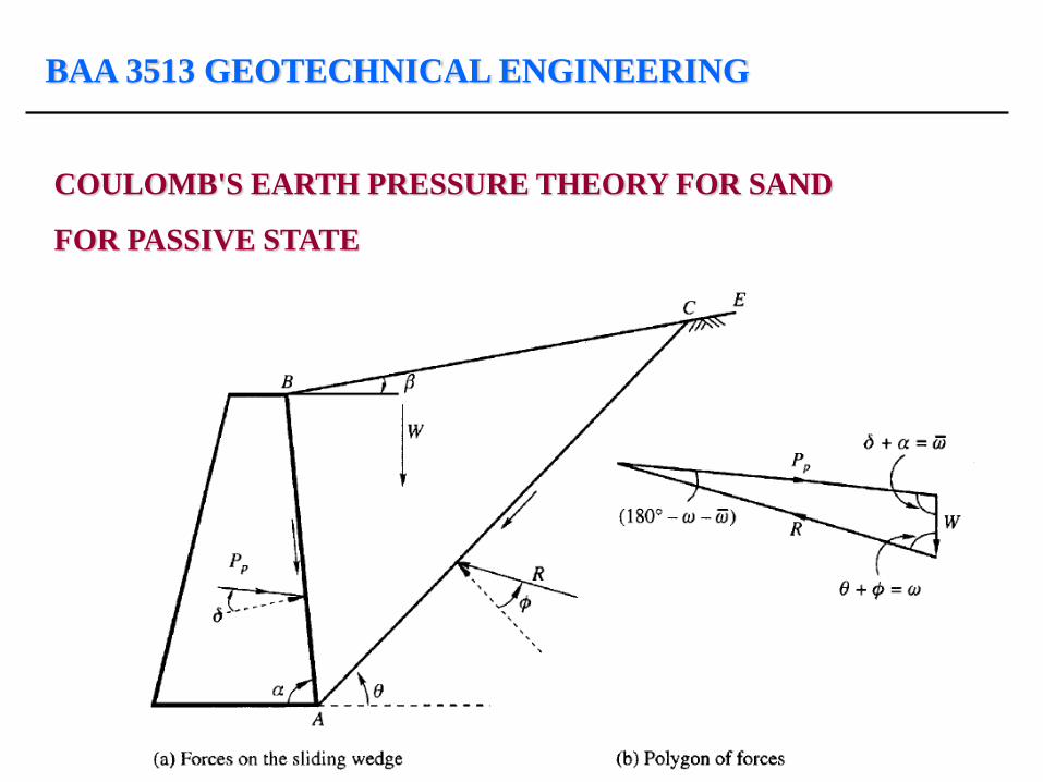
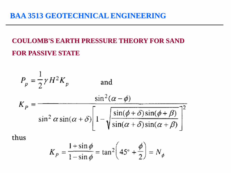
COULOMB'S EARTH PRESSURE THEORY FOR SAND
FOR PASSIVE STATE
BAA 3513 GEOTECHNICAL ENGINEERING
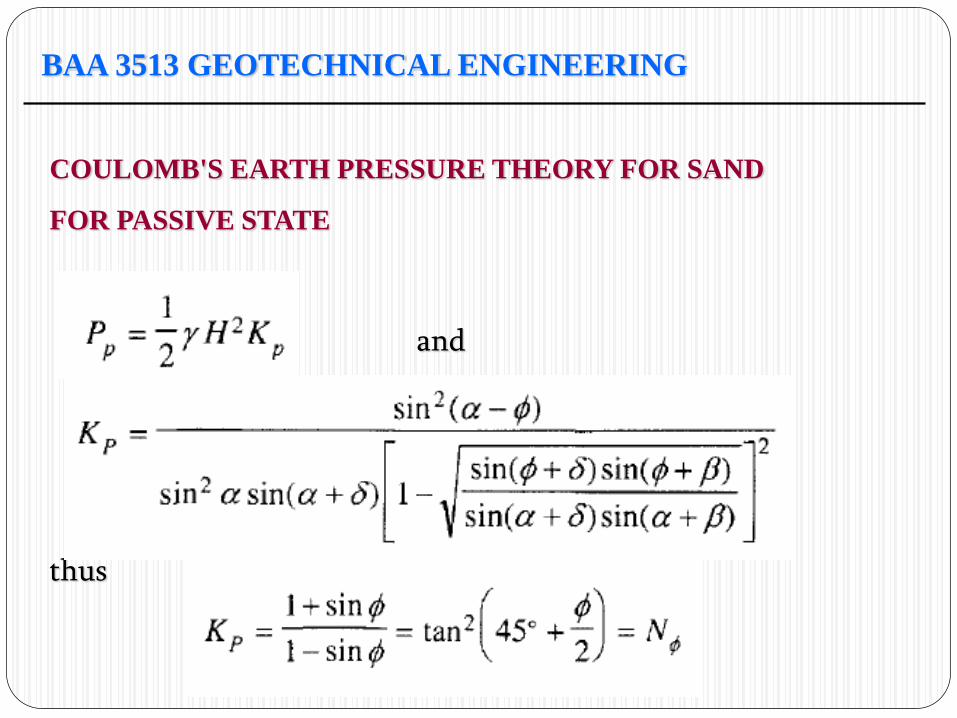
COULOMB'S EARTH PRESSURE THEORY FOR SAND
FOR PASSIVE STATE
and thus
BAA 3513 GEOTECHNICAL ENGINEERING
COULOMB'S EARTH PRESSURE THEORY FOR SAND
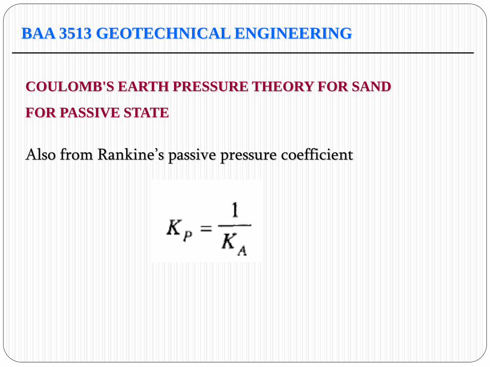
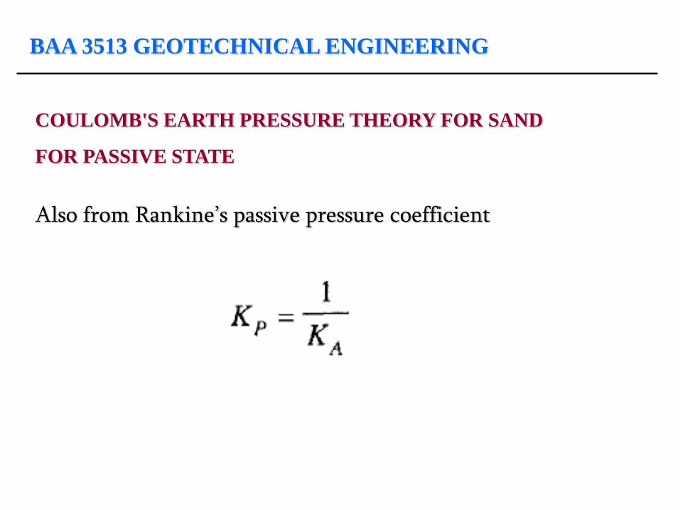
FOR PASSIVE STATE
Also from Rankine’s passive pressure coefficient
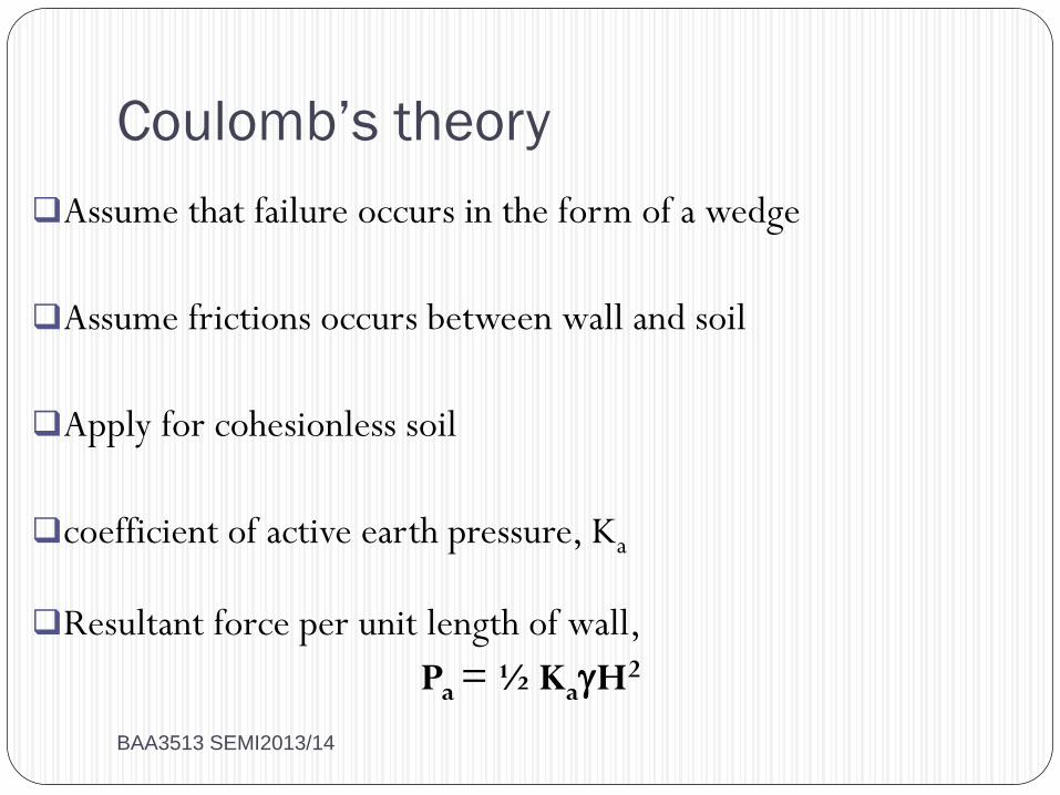
Coulomb’s theory
Assume that failure occurs in the form of a wedge
Assume frictions occurs between wall and soil
Apply for cohesionless soil
coefficient of active earth pressure, Ka
Resultant force per unit length of wall,
Pa = ½ KaH2
BAA3513 SEMI2013/14
BAA 3513 GEOTECHNICAL ENGINEERING
COULOMB'S EARTH PRESSURE THEORY FOR SAND
FOR ACTIVE STATE
Coulomb made the following assumptions in the development of his theory: 1. The soil is isotropic and homogeneous 2. The rupture surface is a plane surface 3. The failure wedge is a rigid body 4. The pressure surface is a plane surface 5. There is wall friction on the pressure surface 6. Failure is two-dimensional and 7. The soil is cohesionless
BAA 3513 GEOTECHNICAL ENGINEERING
COULOMB'S EARTH PRESSURE THEORY FOR SAND
FOR ACTIVE STATE
BAA 3513 GEOTECHNICAL ENGINEERING
COULOMB'S EARTH PRESSURE THEORY FOR SAND
FOR ACTIVE STATE
Consider the figure 1. AB is the pressure face 2. The backfill surface BE is a plane inclined at an angle with the horizontal 3. is the angle made by the pressure face AB with the horizontal 4. H is the height of the wall 5. AC is the assumed rupture plane surface, and 6. is the angle made by the surface AC with the horizontal
BAA 3513 GEOTECHNICAL ENGINEERING
COULOMB'S EARTH PRESSURE THEORY FOR SAND
FOR ACTIVE STATE
Area of wedge ABC = A = 1/2 AC x BD where BD is drawn perpendicular to AC. From the law of sines, we have
BAA 3513 GEOTECHNICAL ENGINEERING
COULOMB'S EARTH PRESSURE THEORY FOR SAND
FOR ACTIVE STATE
The various forces that are acting on the wedge are shown. As the pressure face AB moves away from the backfill, there will be sliding of the soil mass along the wall from B towards A. The direction of the shear stress is in the direction from A towards B. If Pn is the total normal reaction of the soil pressure acting on face AB, the resultant of Pn and the shearing stress is the active pressure Pa making an angle with the normal. Since the shearing stress acts upwards, the resulting Pa dips below the normal. The angle for this condition is considered positive.

BAA 3513 GEOTECHNICAL ENGINEERING
COULOMB'S EARTH PRESSURE THEORY FOR SAND
FOR ACTIVE STATE
The weight of the wedge ABC is W. If Wn is the normal component of the weight of wedge W on plane AC, the resultant of the normal Wn and the shearing stress is the reaction R. This makes an angle with the normal since the rupture takes place within the soil itself. Statical equilibrium requires that the three forces Pa, W, and R meet at a point. Thus, a polygon of forces can be established
BAA 3513 GEOTECHNICAL ENGINEERING
COULOMB'S EARTH PRESSURE THEORY FOR SAND
FOR ACTIVE STATE
From the polygon,
BAA 3513 GEOTECHNICAL ENGINEERING
COULOMB'S EARTH PRESSURE THEORY FOR SAND
FOR ACTIVE STATE
the only variable is and all the other terms for a given case are constants. Substituting for W, we have The maximum value of Pa may be written as
BAA 3513 GEOTECHNICAL ENGINEERING
COULOMB'S EARTH PRESSURE THEORY FOR SAND
FOR ACTIVE STATE
BAA 3513 GEOTECHNICAL ENGINEERING
COULOMB'S EARTH PRESSURE THEORY
BAA 3513 GEOTECHNICAL ENGINEERING
COULOMB'S EARTH PRESSURE THEORY FOR SAND
FOR ACTIVE STATE
where KA is the active earth pressure coefficient. The total normal component Pn of the earth pressure on the back of the wall
BAA 3513 GEOTECHNICAL ENGINEERING
COULOMB'S EARTH PRESSURE THEORY FOR SAND
FOR ACTIVE STATE
If
BAA 3513 GEOTECHNICAL ENGINEERING
COULOMB'S EARTH PRESSURE THEORY FOR SAND
FOR PASSIVE STATE
BAA 3513 GEOTECHNICAL ENGINEERING
COULOMB'S EARTH PRESSURE THEORY FOR SAND
FOR PASSIVE STATE
and thus
BAA 3513 GEOTECHNICAL ENGINEERING
COULOMB'S EARTH PRESSURE THEORY FOR SAND
FOR PASSIVE STATE
Also from Rankine’s passive pressure coefficient
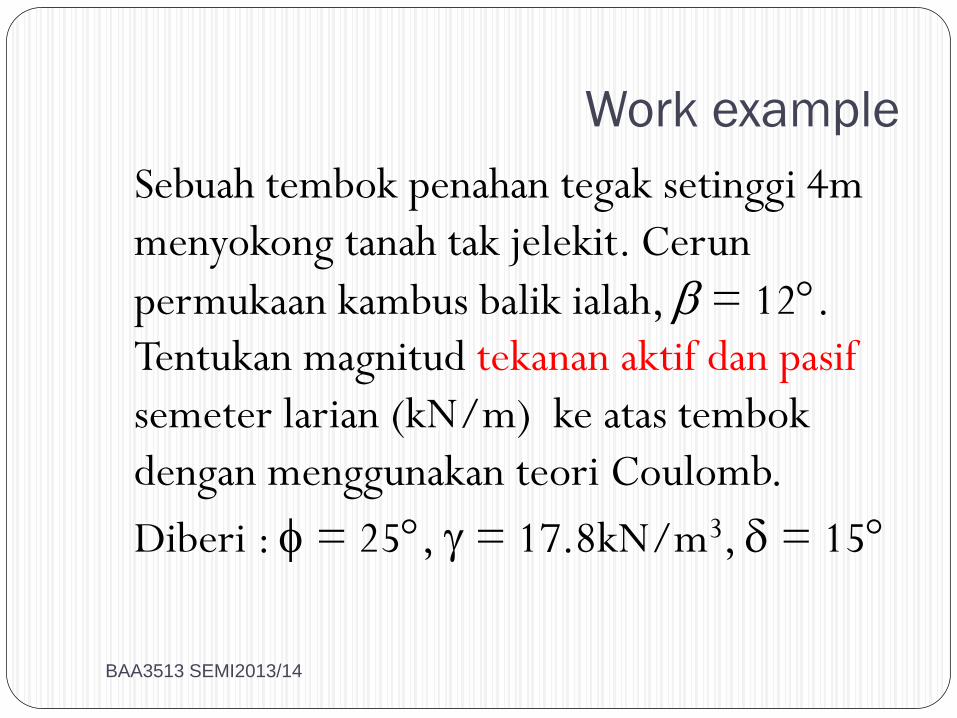
Work example
Sebuah tembok penahan tegak setinggi 4m
menyokong tanah tak jelekit. Cerun
permukaan kambus balik ialah, = 12.
Tentukan magnitud tekanan aktif dan pasif
semeter larian (kN/m) ke atas tembok
dengan menggunakan teori Coulomb.
Diberi : = 25, = 17.8kN/m3, = 15
BAA3513 SEMI2013/14
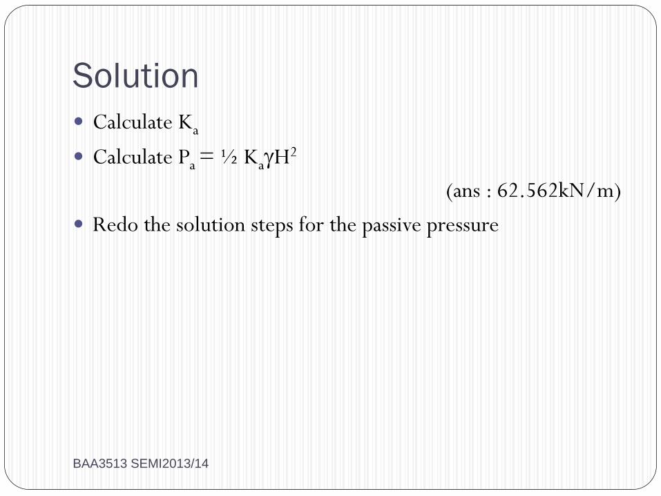
Solution
Calculate Ka
Calculate Pa = ½ KaH2
(ans : 62.562kN/m)
Redo the solution steps for the passive pressure
BAA3513 SEMI2013/14
BAA 3513 GEOTECHNICAL ENGINEERING
CULLMAN LATERAL EARTH PRESSURE
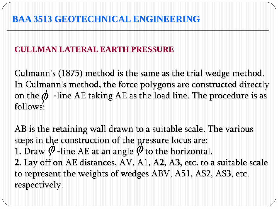
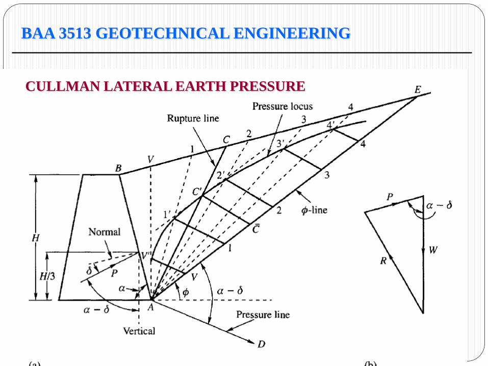
Culmann's (1875) method is the same as the trial wedge method. In Culmann's method, the force polygons are constructed directly on the -line AE taking AE as the load line. The procedure is as follows: AB is the retaining wall drawn to a suitable scale. The various steps in the construction of the pressure locus are: 1. Draw -line AE at an angle to the horizontal. 2. Lay off on AE distances, AV, A1, A2, A3, etc. to a suitable scale to represent the weights of wedges ABV, A51, AS2, AS3, etc. respectively.
BAA 3513 GEOTECHNICAL ENGINEERING
CULLMAN LATERAL EARTH PRESSURE
BAA 3513 GEOTECHNICAL ENGINEERING
CULLMAN LATERAL EARTH PRESSURE
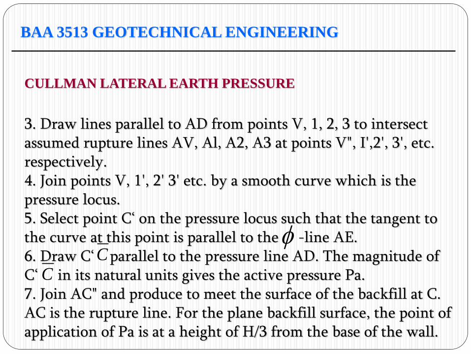
3. Draw lines parallel to AD from points V, 1, 2, 3 to intersect assumed rupture lines AV, Al, A2, A3 at points V", I',2', 3', etc. respectively. 4. Join points V, 1', 2' 3' etc. by a smooth curve which is the pressure locus. 5. Select point C‘ on the pressure locus such that the tangent to the curve at this point is parallel to the -line AE. 6. Draw C‘ parallel to the pressure line AD. The magnitude of C‘ in its natural units gives the active pressure Pa. 7. Join AC" and produce to meet the surface of the backfill at C. AC is the rupture line. For the plane backfill surface, the point of application of Pa is at a height of H/3 from the base of the wall.
C
C

BAA 3513 GEOTECHNICAL ENGINEERING
CULLMAN LATERAL EARTH PRESSURE
3. Draw lines parallel to AD from points V, 1, 2, 3 to intersect assumed rupture lines AV, Al, A2, A3 at points V", I',2', 3', etc. respectively. 4. Join points V, 1', 2' 3' etc. by a smooth curve which is the pressure locus. 5. Select point C‘ on the pressure locus such that the tangent to the curve at this point is parallel to the -line AE. 6. Draw C‘ parallel to the pressure line AD. The magnitude of C‘ in its natural units gives the active pressure Pa. 7. Join AC" and produce to meet the surface of the backfill at C. AC is the rupture line. For the plane backfill surface, the point of application of Pa is at a height of H/3 from the base of the wall.
C
C
Braced cut
Sometimes earth cuts are retained by braced
sheeting rather that the rigid walls which
considered previously
Sheeting were commonly made of wood or
steel
Sheeting are normally driven vertically
Usage : to retain earth temporarily during a
construction project BAA3513 SEMI2013/14
Strut : a horizontal brace providing lateral support to resist earth pressure behind the sheeting
Wale : a continuous horizontal (longitudinal) member extending along a sheeting’s face to provide intermediate sheeting support between strut
Braced cut cannot ordinarily be analyzed by ordinary theories (refer text book for further explanation)
However, the theory will not be discussed further
BAA3513 SEMI2013/14
DON’T FORGET TO DO YOUR EXERCISES !!!!
THE END
BAA3513 SEMI2013/14
Related Documents


