LAST UPDATE: CHANGE 2 (JANUARY 2013)

Welcome message from author
This document is posted to help you gain knowledge. Please leave a comment to let me know what you think about it! Share it to your friends and learn new things together.
Transcript


87th Stray dogs | Standard Operating Procedures | 2013 | Change 2 Page 2
1 INTRODUCTION .......................................................................................................................... 6
1.1 BACKGROUND............................................................................................................................................................... 6
2 STANDARD MISSION PROCEDURES ........................................................................................ 7
2.1 TIME REFERENCE ........................................................................................................................................................ 7
2.2 PERSONAL PC SETUP ................................................................................................................................................. 7
3 STANDARD MULTIPLAYER PROCEDURES ............................................................................. 9
3.1 BRIEFING....................................................................................................................................................................... 9 3.2 CONNECTING TO A MULTIPLAYER GAME ..............................................................................................................10
3.3 ENTERING THE FALCON 3D WORLD ....................................................................................................................10
4 GROUND OPERATIONS (BASIC IQT)......................................................................................11
4.1 FALCON LAUNCH OPTIONS ......................................................................................................................................11 4.2 CHECK-IN ORDER: .....................................................................................................................................................12
4.3 FUEL MANAGEMENT .................................................................................................................................................12
4.4 EXTERNAL LIGHTS SETTINGS (DAY/NIGHT) .......................................................................................................13
4.5 ALTIMETER SETTING ................................................................................................................................................14 4.6 STANDARD TAXI SPACING .......................................................................................................................................15
4.7 STANDARD LINEUP AND TAKE-OFF .......................................................................................................................16
4.8 AIR-TO-AIR TACAN (AA TCN) SETTINGS...........................................................................................................17
18
5 STD. DEPARTURE......................................................................................................................18
5.1 ABORT TAKE-OFF ......................................................................................................................................................19
5.2 AIR ABORTS: ..............................................................................................................................................................19
5.3 AFTERBURNER TAKE-OFF .......................................................................................................................................19
6 STD. IN-FLIGHT PROCEDURES ...............................................................................................20
6.1 TACTICAL FREQUENCY .............................................................................................................................................20
6.2 INITIAL CHECK IN ......................................................................................................................................................20
6.3 STANDARD FORMATIONS .........................................................................................................................................21 6.4 REJOINS .......................................................................................................................................................................21
6.5 OVERSHOOT................................................................................................................................................................22
6.6 LEAVING FORMATION ...............................................................................................................................................22
6.7 LOST WINGMEN .........................................................................................................................................................22 6.8 OPS CHECK .................................................................................................................................................................23
6.9 STATE CHECK .............................................................................................................................................................23
6.10 MINIMUM FUEL AND EMERGENCY FUEL CALLS ..................................................................................................23
7 STD. RECOVERY.........................................................................................................................25
7.1 THE TRAFFIC PATTERN ............................................................................................................................................25 7.2 PATTERN TERMINOLOGY .........................................................................................................................................25
7.3 EXECUTION .................................................................................................................................................................26
7.4 JOINING THE OUTER CIRCUIT ..................................................................................................................................26
7.5 JOINING THE INNER CIRCUIT...................................................................................................................................26 7.6 MANDATORY POSITION REPORTS .........................................................................................................................28

87th Stray dogs | Standard Operating Procedures | 2013 | Change 2 Page 3
7.7 AIRMANSHIP OUTER CIRCUIT .................................................................................................................................28 7.8 AIRMANSHIP IN THE INNER CIRCUIT ....................................................................................................................28
7.9 FACTORS AFFECTING THE CIRCUIT ........................................................................................................................29
7.10 WEIGHT CONSIDERATIONS .....................................................................................................................................29

87th Stray dogs | Standard Operating Procedures | 2013 | Change 2 Page 4
FROM: Virtual Fighter Wing - 87th Straydogs
SUBJECT: Standard Operating Procedures
DISTRIBUTION: Internal use but can be releasable to the public
Virtual Fighter Wing
87th Straydogs
Several authors have over the years contributed the content of this document. This latest
release of the “87th VFW Standard Operation Procedures” is therefore a gathering of previous
knowledge and some new and updated sections to accommodate changes within the virtual
wing but also the current version of the simulation released by
The aim of this document is to provide a brief overview of the operating procedures required
for basic IQT. It may also serve as a quick reference for procedures used within the daily
activities of virtual flying with the stray dogs.
Husky
872ND VIRTUAL
SQUADRON

87th Stray dogs | Standard Operating Procedures | 2013 | Change 2 Page 5
Abbreviations:
AA TCN Air-to-Air Tacan Channel
ATC Air Traffic Control
AOB Angle of bank
AoA Angle of attack
VMC Visual Methological Conditions
MC Mission Commander
IFR Instrument Flight Rules
VFR Visual Fight Rules
SOP Standard Operating Procedures
TS TeamSpeak
UI User Interface (include 1st and 2nd chat)
TE Tactical Engagement
T/O Take off
EoR End of Runway
RAT Radar Assisted Trail

87th Stray dogs | Standard Operating Procedures | 2013 | Change 2 Page 6
1 Introduction
1.1 Background
The whole purpose of Standard Operations
Procedures within the virtual wing of 87th
Stray dogs (87TH F-16 SOP) is derived from
the desire to simplify mission planning and
reduce the workload of wingmen. The 87TH
SOP therefore describes relevant
procedures used in simulated aviation to
and from the Tactical Area of Operation
(Training or War). All members of our
virtual squadron are strongly encouraged
to read, remember and use the SOP to its
fullest in their daily activities thereby also
providing a solid learning platform from
which new members can benefit.
Deviations from SOP are acceptable if:
1. Deviation is briefed
2. The deviation does not affect flight
safety in any way
In short: Non-briefed events or mission
items are considered to be SOP and the
officer in charge of the briefing can merely
call a point in the briefing to i.e. “ground
ops according to 87th SOP”. Flight leads
should brief any items that are non-
standard (i.e. according to this document)
in addition to normal mission details.

87th Stray dogs | Standard Operating Procedures | 2013 | Change 2 Page 7
2 Standard Mission Procedures
2.1 Time reference
Due to the international nature of our
operations, we state our daily operation
activities using UTC or Zulu time. Any pilot
can see the current UTC time by accessing
the first page on our website:
2.2 Personal PC setup
All members are responsible for the
functionality and correct installation of
BMS. This includes but is not limited to
bullet point 1-6 below. All unnecessary
programs including TeamSpeak (TS) must
be shut down prior to establishing
connection to mission host or if open move
into the sub channels for each flight.
1. Computer system optimized with
virus scanners disabled and
routers/firewalls configured &
tested for multiplayer (MP)
operations.
2. Internet connection tested
3. Voice communications tested for
clarity and volume settings
4. HOTAS programmed and working
as desired.
5. TrackIR programmed and working.
6. If a pilot has multiple installs,
ensures the correct one is running
and configured properly.
Bullet point 1-3 can be accomplished by
asking a fellow Stray dog in IRC/
TeamSpeak to do a connection test.
Mission hosts should preferable be the
member with the fastest internet
connection and most powerful PC. The
voice server in use (ivc3.87th.org) and

87th Stray dogs | Standard Operating Procedures | 2013 | Change 2 Page 8
connection bandwidth must be briefed
prior to initiation of a multiplayer flight.
UHF and VHF radio configuration
should be briefed. This will normally
consist of the tower frequency in UHF
for ground ops and the flights assigned
victor frequencies. The package UHF
frequency will be established as well.
The host or package commander may
skip using the tower frequency and use
the package frequency to facilitate a
quicker radio check-in. The assigned
channels will be based on flight no. in
the package.

87th Stray dogs | Standard Operating Procedures | 2013 | Change 2 Page 9
3 Standard Multiplayer Procedures
3.1 Briefing
Briefings may be accomplished in
IRC/TeamSpeak and/or in the falcon user
interface (1st chat) with voice. Mission
designer are encouraged to make data
cards available using the Weapon Delivery
Planner:( )
software by Falcas. The software is under
constant development – check his website
for the latest version. This software is
capable of importing data from *.tac files.
Such data cards combined with an *.ini file
that plot SAM engagement zones, AOR
boxes/lines, FLOT, etc. should preferable
be made available for download.
The mission designer will give an
appropriate briefing applicable to the
mission type and take pilot skill into
consideration when describing tactics,
techniques and procedures. The briefer
should brief “what they know” and to the
level of their skill and ability. If there is a
more experienced pilot present and you
have questions about something, feel free
to ask them. Time is always a factor that
must be dealt with when balancing briefing
depth. Designers are encouraged to build
briefing slides or notes and email them to
pilots a day or two in advance to maximize
flight time and enhance mission planning
effectiveness.
All pilots will meet in our preferred
communication software (currently
TeamSpeak) prior to launch and perform

87th Stray dogs | Standard Operating Procedures | 2013 | Change 2 Page 10
the briefing. Briefings should be performed
prior to establishing connection to the
mission host since chat in the UI can
interfere with pilots flying in the 3D world.
Pilots should change their IRC nick to “call
sign-nick” during briefings to indicate they
are part of a mission briefing in progress.
3.2 Connecting to a multiplayer game
The mission or game host will tell when the
“host is up”. Each pilot will ensure the
briefed game IP, client bandwidth and IVC
server is set connecting to the host. After
getting in the UI, each pilot shall
accomplish a radio check with the host (or
another pilot if needed). Once all pilots are
accounted for, any short last briefing items
should be accomplished. Again, limited
communication using F1 and F2 since this
is interfering with people, who already fly.
When the host enters the Tactical
Engagement (TE) it will become available
online, and pilots should enter 2nd chat and
should stop their clocks.
3.3 Entering the Falcon 3D world
The game host will call “C/S launching
ramp or taxi” and pilots now launch to
either ramp (T/O -20 min) or taxi (T/O -4
min) and should report “C/S launching”.
All flight members join the 3D world and
checks in by typing “in”.

87th Stray dogs | Standard Operating Procedures | 2013 | Change 2 Page 11
4 Ground Operations (Basic IQT)
4.1 Falcon launch options
Ground operations refer to procedures
performed while the jet is on the ground
and include startup, establishment of radio
contact, ground checks, taxi speed, line-up
and take-off procedures. Lead should
initiate radio contact no later than 15 min.
prior to T/O and taxi out in order to arrive
at the End of Runway (EoR) at least 4
minutes prior T/O. This will allow
sufficient time for final checks (SLIPER)
and is important when flying in larger
packages.
Ramp start: When entering the jet
the canopy will be open. Each pilot now
starts his engine and closing of the canopy
should be done after the JFS switches to
OFF to indicate you have no problems with
engine and throttle. In addition, the lights
are set to STEADY to indicate a human is
operating the a/c (See External lights
settings (day/night) for details below).
Afterwards perform needed checks to be
ready for the radio check on the flights
assigned VHF channel 15 min. prior to
takeoff (T/O). Lead will check the flight in.
Wingmen will inform the flight lead of any
problems via voice otherwise lead will
assume all systems are green. Once the INS
is aligned wingmen will indicate ready to
taxi by setting position lights to FLASH and
landing light ON - no radio communication
needed. Flight leads may elect to skip the
full 8 min. INS alignment for time
constraints. This procedure can be briefed
as “87th short alignment”.
Taxi start: When entering the jet set
the lights to STEADY to indicate that the

87th Stray dogs | Standard Operating Procedures | 2013 | Change 2 Page 12
a/c is manned by a human. Set the radios to
the briefed frequencies and wait for lead to
perform the check-in.
Note: Avionics programming can be done
in the jet but can also be performed prior
to entering the 3D world using the Weapon
Delivery Planner, and subsequently loaded
into the jet w/ the DTC during ramp or taxi
starts. Additional programming may be
done during the climb out and/or FENCE
check but do not be distracted by excessive
cockpit avionics activity when airborne.
4.2 Check-in order:
In neither of the starts do the wingmen
make radio checks on UHF. The lead will
initiate the UHF and VHF check.
“Snake11 check victor: “2”, “3”, “4”.
Once VHF radio contact has been
established lead will initiate a UHF check
on the local tower – respond using call sign.
“Snake11 check: “Snake 12”, “Snake 13”, “Snake 14”.
Again, only the flight lead may
request taxi instructions on the local tower
frequency and only lead will report ground
movements on tower.
4.3 Fuel management
Fuel management is considered the most
important part of aviation since lack of fuel
will force the pilot into stressful situations
and in some cases loss of airframe and even
the pilot himself. Therefore, pilots should
at all times be aware of their fuel state.
Joker fuel is set using the ICP and prior to
taxi.
Joker Fuel: A pre-briefed fuel state, which
allows completing a certain event and
arriving at bingo fuel after this event. Joker
fuel is based on engaged fuel flow (1,000
pounds per minute) and maneuvering time
required to extract the F-16 from the fight.
If the flight is not engaged and Joker is
reached, then immediate exit is logical,
even though more than enough gas is
available for recovery.
Bingo fuel: A pre-briefed fuel state which
allows the a/c to return to the base of
intended landing or alternate, if required,
using preplanned recovery parameters and
arrive at the destination with a pre-
planned fuel state.
Normal Recovery Fuel: The fuel on initials
or start an instrument final approach at the
base of intended landing or alternate 1,000
pounds (Blocks 10-32) and 1,200 pounds
(Blocks 40+).
Minimum Fuel: The fuel on initials or start
an instrument final approach at the base of
intended landing or alternate 800 pounds
(Blocks 10-32) and 1,000 pounds (Blocks
40+).
Emergency Fuel: The fuel on initials or
start an instrument final approach at the
base of intended landing or alternate 600
pounds (Blocks 10-32) and 800 pounds
(Blocks 40+).

87th Stray dogs | Standard Operating Procedures | 2013 | Change 2 Page 13
The fuel requirement is calculated
backwards starting with a predetermined /
required fuel state at the recovery base.
Bingo is calculated from the furthest point
en-route, to the recovery base on a
convenient route and altitude.
4.4 External lights settings (day/night)
Pilots will start up the a/c; apply electrical
power and set lights to STEADY (Table 1).
Once the engine lights up successfully then
CLOSE CANOPY. After final checks and
when ready to taxi, pilots will turn landing
lights ON and lights FLASH. Lead will be
last to set “ready to taxi” lights after the
entire flight has fully operational jets. The
entire flight will then taxi to arrive at EoR 4
min. prior to T/O. At EoR the pilot will set
lights to STEADY to indicate final checks
are being performed and only when
completely ready for T/O the pilot should
change to FLASHING lights and both
landing and anti-collision lights should be
turned on (Table 1). The usage of
communication for the flights a/c state
should be used if the a/c lights are not
visible. External light SOP settings favor a
communication free environment from
ramp to takeoff. This does not mean that if
lead decides to use the radios, that the
flight members can disregard the external
light SOP setting.
Note: During night operations position
lights STEADY and anti-collision light OFF
during the entire mission (Ground
operations and when airborne), unless
otherwise requested by wingmen.
Table 1: Quick reference to external day light settings at various ground points
Point Master Position Anti-collision Landing light (b)
Enter the jet (a) NORM STEADY OFF OFF
Ready to taxi NORM FLASH OFF ON
End of runway (EoR) NORM STEADY OFF OFF
Ready for T/O (C) NORM FLASH ON ON a) Apply electrical power, lights to steady even though the lights will not be visible before successful engine start in BMS.
b) Same as taxi light in BMS we need it in order to see and as “visual signal”.
c) This setting should be used when all internal checks (SLIPER) and avionic settings are complete.

87th Stray dogs | Standard Operating Procedures | 2013 | Change 2 Page 14
4.5 Altimeter setting
All 87th pilots should use hecto pascal (hPa)
for their altimeter settings. Hence, make
sure you have unchecked the “Use Hg
Altimeter” (Figure 1).
Figure 1: The Falcon BMS Configuration
QNH is defined as, "barometric pressure
adjusted to mean sea level." It is a pressure
setting used by Air Traffic Control (ATC) to
refer to the barometric setting which, when
set on an aircraft's altimeter, will cause the
altimeter to read altitude above mean sea
level within a certain defined region. Such
pressure setting for the local airbase can be
obtained by calling the tower (ATC menu
page 2 - QNH) and can be set on the
altimeter using wheel on the mouse. The
transition altitude (TA) is the altitude
above sea level at which a/c change from
the use of altitude to the use of flight levels.
When operating at or below the TA,
altimeters are usually set to show the
altitude above mean sea level (QNH).
Above the TA, the aircraft altimeter
pressure setting is adjusted to the standard
pressure setting (SAS) which is QNE (29.92
in/Hg or 1013 hPa) and aircraft altitude
will be expressed as a flight level. While use
of a standardized pressure setting
facilitates separation of aircraft from each
other, it does not provide the aircraft's
actual height above ground. The transition
altitude in BMS is fixed at 14.000‘. Hence,
below 14.000’ we operate on local QNH
settings provided by tower, while above we
use QNE. The F-16 avionics are capable of
providing altitude based on the
measurement of atmospheric pressure
(BARO). The altitude shown in the HUD
will be information provided from the
barometric altimeter. Setting the altimeter
to (RADAR) will provide the pilot with
height above ground. The RADAR altimeter
is also a component of the terrain
avoidance warning systems, warning the
pilot if the aircraft is flying too low, or if
there is rising terrain ahead. When RADAR
is selected the altitude shown in the HUD
display will be fed from the radar altimeter.
The last option is (AUTO) and the altitude
shown in the HUD display will be fed from
the radar altimeter or the barometric
altimeter. If either jet altitude is at/below
1500’ AGL and the jet is ascending or if the
altitude is at/below 1200’ AGL and the jet

87th Stray dogs | Standard Operating Procedures | 2013 | Change 2 Page 15
is descending, then altitude above ground
level (AGL) is displayed, otherwise
barometric altitude is used.
4.6 Standard Taxi spacing
Minimum taxi spacing is 150’ staggered or
300’ in trail and at night 300’ on the
centerline of the taxiway. Spacing can be
approximated by matching the F-16 engine
nacelle with the FPM, (i.e., FPM is the size
of the burner can) or to hold the
proceeding aircrafts main gear at the 1.25
deg. nose low pitch line. Taxi speed in clear
areas should not exceed 25 knots and 10
knots during turns. (Figure 2).
Figure 2: How to judge distance using the HUD
If the amount of aircraft on a taxiway
require compression of taxi spacing (on
large exercises, or when operationally
needed), it is authorized to close in to the
preceding F-16 to 150’, every F-16 on own
side of the taxi track.
At holding point or EoR the A/C are
positioned on the lines drawn on the
ground (or at a 45° angle to the runway).
Perform the SLIPER check even though the
IFF is not implemented in BMS:
Speed brakes IN
Landing light ON
IFF (not implemented in BMS)
Probe heat ON
Ejection seat ARM
Radar ON.
To indicate that the aircraft looks normal
and you are ready for take-off turn on
landing lights and anti-collision lights
(Table 1).

87th Stray dogs | Standard Operating Procedures | 2013 | Change 2 Page 16
4.7 Standard lineup and take-off
Individual aircraft will line-up on the
centerline of the runway. Subsequent
aircraft will not enter the runway until the
preceding aircraft has rolled at least
1000‘down the runway. If remaining take
off distance is critical, execute single ship
take-offs. Formations will line-up in
elements, with the lead on the downwind
side.
Two-ship: Each jet takes center of their
side of the RWY. #2 lines up main gear tires
on #1 as viewed from his cockpit. Number
two will lineup on the upwind side to avoid
leads jet wash.
Figure 3: Two-ship line-up
Three-ship: Echelon into the wind. #1 puts
wingtip over the edge of the runway. #2
lines up on the centerline on the upwind
side and #3 puts his wingtip on the
opposite side on the upwind side of #2.
Figure 4: Three-ship line-up
Four-ship: Lineup with “3-in-the-slot”. #1
puts wingtip over the edge of the runway
on the downwind and #2 putting the
missile rail (nearest lead) on the centerline
of the RWY. #3 should split the difference
between #1 and #2 and pull forward until
lining up #2s afterburner. #4 should line
up on #3 w/ the same spacing that #1 and
#2 have
Figure 5: Four-ship line-up
Use 15s spacing after brake release or until
the preceding a/c is airborne, whichever

87th Stray dogs | Standard Operating Procedures | 2013 | Change 2 Page 17
occurs last for standard VFR departure and
20s for IFR departures.
4.8 Air-to-air Tacan (AA TCN) settings
The overall assumption is that each
element will be in formation. Hence, only
#1 needs to be tied to #3 and #2 to #4. This
setup enables easy access to cross check by
toggling between “X” and “Y” as this will
provide the alternate information. Toggling
from the below plan should be momentary,
with an immediate return to the briefed
setting. Every call sign will default to their
assigned TACAN setting based on IDM
number in the briefing. E.g. if your flight is
listed as the first flight in a package (IDM
no. 1) in the briefing screen – the lead of
that flight should by default set AA TCN to
11Y. Subsequent listing will be IDM 2, IDM
3 etc.
Table 2 Air-to-Air Tacan default settings
Two-ship (#1/#2)
1st flight 11Y/74Y
2nd flight 12Y/75Y
Four-ship Lead element (#1/#2) Second element (#3/#4)
1st flight 11Y/74X 74Y/11X
2nd flight 12Y/75X 75Y/12X
If tactics increase the probability of wingmen splitting from formation or do not rely heavily
on inter-element cooperation, leads may favor tying element mates together e.g. 12X/75X,
12Y/75Y.

87th Stray dogs | Standard Operating Procedures | 2013 | Change 2 Page 18
5 Std. Departure
The below standard departure procedures
are used during single-ship, VRF and IFR
conditions as basic IQT do not include
formation take-offs.
Visual Trail Departure Take-off into a 350
KCAS / 0.80M / 725 FTIT climb. Use 15s
spacing after brake release or until the
preceding a/c is airborne, whichever occurs
last. Wingmen join to Fighting Wing, trailing
elements join 1-2 NM trail. When visual and
able to remain visual call:
"C/S, visual"
Radar Assisted Trail (RAT): In the event a
trail departure is required to be flown and an
immediate rejoin is not feasible (weather) a
RAT will be flown. All flight members must
follow the departure and formation contracts
for airspeed, bank angles, and power settings.
Take-off into a 350 KCAS / 0.80M / 725 FTIT
climb. Use 20s spacing after brake release or
until the preceding a/c is airborne,
whichever occurs last. Turns are performed
at 300 of bank. The wingmen should not get
any closer than 1nm. When FCR lock can be
achieved with preceding A/C report:
“C/S, tied"
To maintain formation allow the preceding
a/c to drift 50 from the center of the multi-
function display (MFD) for each mile of
separation or delay approx. 20s from the
“turning” call when no radar contact have
been established. E.g. to maintain a 2NM trail
position let the preceding a/c drift 100 before
initiating the turn. Rejoin to briefed
formation on top when visual. If no FCR lock
can be achieved report:

87th Stray dogs | Standard Operating Procedures | 2013 | Change 2 Page 19
"C/S, negative tied"
In this case all flight members will execute
snake climb procedures. Snake climbs
require a minimum of 1000’ vertical
separation between flight members.
Separation will be maintained by means of
radio-calls by the formation members
initiated by lead at least every 5000’. All
turns will be called by lead a maximum of 900
of turn can be made until all formation
members have established radar lock. At all
times the wingmen are responsible for
collision avoidance. When VMC and able to
remain VMC call "C/S, visual" and rejoin to
briefed formation.
RAT Notes: The first decision is whether to
lock the previous aircraft or to fly a no-lock
RAT. A no-lock RAT allows pilots to clear
their flight path and maintain better SA, but it
is normally easier to maintain precise
position and “TIED” with a lock (STT). Ensure
the cursor is precisely placed over the correct
a/c prior to commanding a lock. The use of
ACM mode to gain a lock in the weather is
NOT permitted. All locks should be verified
by ensuring the target is at the correct range,
azimuth and altitude, and is flying the proper
ground track at the briefed airspeed. If in
doubt, immediately return to a search mode
to regain and ensure SA. Use of horizontal
situation display (HSD) and data link systems
can greatly increase SA at this point if
operating correctly.
5.1 Abort take-off
If a take-off abort takes place:
Transmit the abort state on tower
frequency when time permits.
Following aircraft will automatically
abort or hold position until aborting
aircraft is clear of runway.
A take-off abort above 100Kts will be
considered a ‘hot brakes' condition,
and will be treated accordingly.
5.2 Air Aborts:
If an abort occurs after takeoff, all aircraft
will maintain their original numerical call
sign. Aborting aircraft with an emergency
condition will be escorted to the field of
intended landing. When other than an
emergency condition exists, the flight lead
will determine if an escort for the aborting
aircraft is required.
The mission will be aborted, regardless
of apparent damage or subsequent normal
operation for all flight control system
anomalies
5.3 Afterburner take-off
Afterburner cancellation is normally
performed at 300 KCAS, unless operations
dictate otherwise. Element or wingmen can
delay the cancelation in order to expedite the
join-up.
6 Std. In-flight Procedures
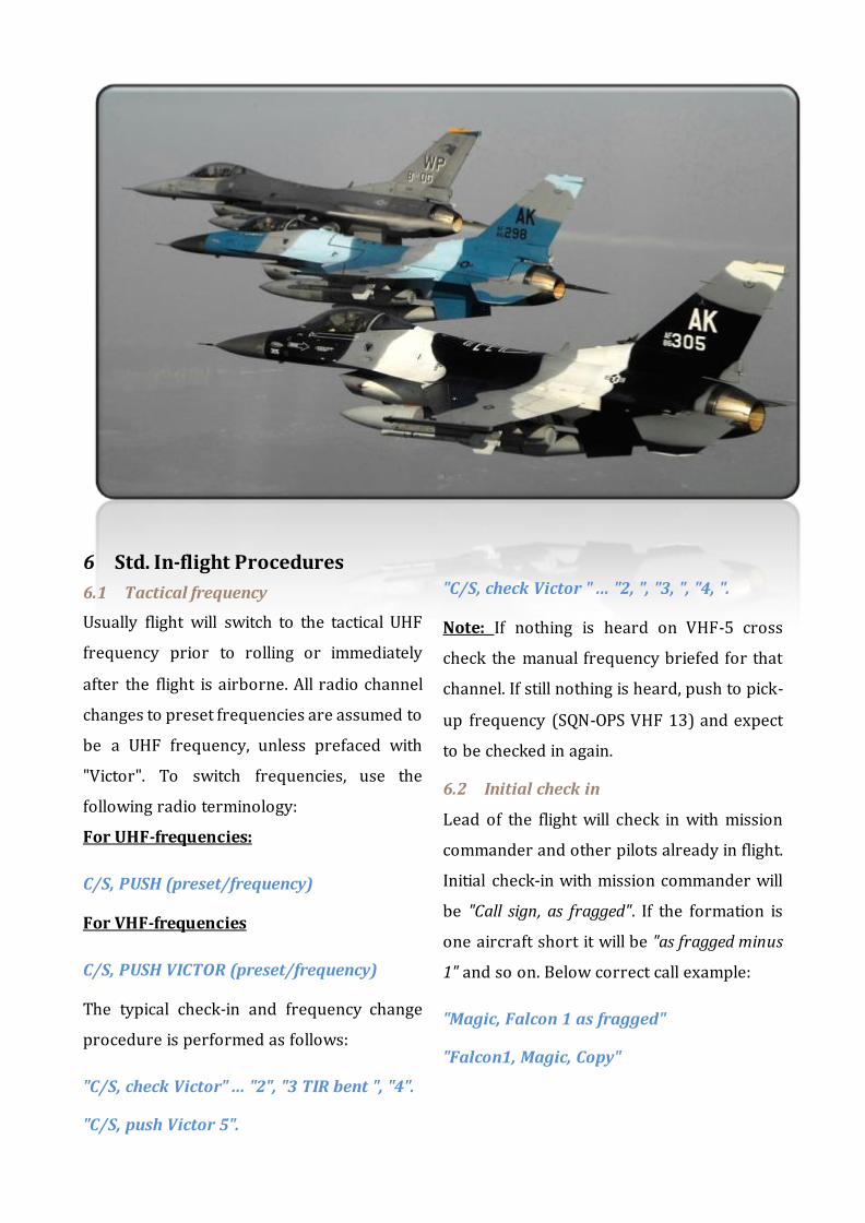
6.1 Tactical frequency
Usually flight will switch to the tactical UHF
frequency prior to rolling or immediately
after the flight is airborne. All radio channel
changes to preset frequencies are assumed to
be a UHF frequency, unless prefaced with
"Victor". To switch frequencies, use the
following radio terminology:
For UHF-frequencies:
C/S, PUSH (preset/frequency)
For VHF-frequencies
C/S, PUSH VICTOR (preset/frequency)
The typical check-in and frequency change
procedure is performed as follows:
"C/S, check Victor" ... "2", "3 TIR bent ", "4".
"C/S, push Victor 5".
"C/S, check Victor " ... "2, ", "3, ", "4, ".
Note: If nothing is heard on VHF-5 cross
check the manual frequency briefed for that
channel. If still nothing is heard, push to pick-
up frequency (SQN-OPS VHF 13) and expect
to be checked in again.
6.2 Initial check in
Lead of the flight will check in with mission
commander and other pilots already in flight.
Initial check-in with mission commander will
be "Call sign, as fragged". If the formation is
one aircraft short it will be "as fragged minus
1" and so on. Below correct call example:
"Magic, Falcon 1 as fragged"
"Falcon1, Magic, Copy"

87th Stray dogs | Standard Operating Procedures | 2013 | Change 2 Page 21
6.3 Standard formations
The standard two-ship formation is fighting
wing. This formation gives the wingman a
maneuvering cone from 30 to 60 degrees aft
of line abreast and lateral spacing between
500' to 3000' (<0.5 nm). #2 maneuvers off
lead with cutoff as necessary to maintain
position. This formation is employed in
situations where maximum maneuvering
potential is desired. Arenas for use include
holding in a tactical environment or
maneuvering around obstacles or clouds. The
wingman should at all times avoid the deep 6
o’clock position.
Figure 6: Standard two-ship formation
The standard three-ship formation is
fluid three with one aircraft missing and
wingman in fighting wing. #3 is element lead
in line abreast with 4000-12000’ spacing but
strives for 6000’ (1nm).
Figure 7: Standard three-ship formation
The standard four-ship formation is
fluid four. Element leads fly line abreast with
their wingmen in fighting wing. This
formation gives good maneuverability;
wingmen are kept close and it’s easy to
eyeball the entire formation. On the
downside this formation provides reduced
defensive action due to the proximity of
aircraft.
Figure 8: Standard four-ship formation
Below canopy angle curs are provided and
should be used as in flight reference angles
for the pilot (Figure 9).
Figure 9: Canopy angle cues
6.4 Rejoins
During straight-ahead rejoins #1 should
maintain 350 knots unless otherwise briefed

87th Stray dogs | Standard Operating Procedures | 2013 | Change 2 Page 22
and #2 rejoins to the left wing, while #3 + #4
rejoin to the right.
In a turning rejoin #1 will maintain 350
knots and 30 to 45 degrees of bank. Flight
members maintain 400 knots. #2 rejoins on
the inside wing #3 + #4 join to the outside
wing. If the rejoin subsequently becomes
straight-ahead (#1 rolls out) continue to the
wing originally maneuvering toward (do not
reset to the straight-ahead contract).
A radar lock-on may be used during the
rejoin to provide range and overtake
information.
6.5 Overshoot
If the overtake is excessive and cannot be
controlled with power and speed brakes,
initiate an overshoot.
In a straight-ahead overshoot, check
away from #1 and stay slightly low on the
formation. Keep lead in sight, stabilize, move
back fighting wing.
In a turning overshoot reduce bank and
slide to the outside of the turn. Ensure nose-
tail separation and pass behind and below
#1. Once line of sight begins moving forward,
perform a normal cross-under to the inside
wing. Stabilize and then move into fighting
wing.
6.6 Leaving formation
It is the duty of the wingman to leave the
formation:
1. When directed to do so.
2. When visual is lost.
3. When unable to join up or to stay in
formation without crossing over,
under, or in front of the aircraft ahead.
4. At any time you feel that your
presence in the formation constitutes
a hazard.
5. When pilots leave formation, clear the
flight path in the direction of the turn
and notify lead. If pilots have lost
sight, comply with the appropriate
lost wingman procedures. Rejoin
6. Only when directed by lead.
6.7 Lost wingmen
In any lost wingman situation, immediate
separation of aircraft is essential.
In wings-level flight (climb, descent or
straight-ahead) inform #1 with a blind call
and turn away using 150 of bank for 15s, then
resume heading. If outside in a turn then
reverse the direction of turn using 150 of
bank for 15s and inform #1. Continue
straight ahead to ensure separation prior to
resuming the turn.
If inside in a turn then momentarily
reduce power to ensure nose-tail separation
and inform #1 to roll out of the turn.
Maintain angle of bank to ensure lateral
separation. #1 may resume the turn only
when separation is ensured
Once lost wingman procedures have been
executed, permission to rejoin the flight must
be obtained from the flight lead.

87th Stray dogs | Standard Operating Procedures | 2013 | Change 2 Page 23
6.8 OPS check
Flight lead will call OPS check (format AL /
FR / Totalizer / Tank(s) feeding / dry). Flight
member will readout in flight order using the
same format as lead. Tank(s) Dry" will be
added only on first OPS check where the
external tanks are empty and will not be used
again for tanks dry will be assumed.
“C/S ops check, 1 is 27, 32, 10.5, feeding”
“2 is 27, 31, 10.2 feeding”
Accomplish sufficient ops checks to ensure
safe mission accomplishment. Additionally,
each pilot should monitor the fuel system
carefully throughout the flight to identify low
fuel, trapped fuel or an out of balance
situation as soon as possible. During tactical
maneuvering and/or engagements the lead
should use STATE CHECK instead due to the
less time required used to accomplish the
check.
6.8.1 Ops checks are required:
During climb or at level-off after take-off.
When external fuel tanks are empty.
Prior to entering an air-to-surface range,
once while on the range if multiple passes
are made and after departing the range.
6.9 State check
Format will be "C/S, state fuel" or "C/S, state
missiles". The call "C/S, state" will imply both.
Fuel: Two words. First word is fuel in
thousands; second word is fuel in hundreds.
Therefore: 10,200 = "Ten Two" and 4,500 =
"Four Five" Feeding is assumed. At the first
check everybody will call their actual fuel
state. "Tank(s) Dry" will be added on the first
fuel check when the external tanks are
empty.
Missiles: "[# Aim-120s], [# Aim-7s] [# Aim-
9s]." A full load of gun is assumed. Example if
402: "Four Zero Two". Even though we don’t
carry semi-active missiles in BMS we
maintain the USAF standard.
Use of "Same": If other flight members are
within ± 500Ibs, above bingo and have the
same weapons load, the flight member will
call "Same", otherwise give a full
fuel/missiles call. Reference will be the
previous flight member. If in doubt, give a full
radio call.
"C/S state: Eleven Eight, Four Zero Two"
"Two Same"
"Three Same"
"Four: Eleven Two, Four Zero One"
6.10 Minimum fuel and emergency fuel calls
As explained previously the fuel state of the
aircraft is of utmost importance and each
pilot is responsible for joker and bingo
settings. In addition to joker and bingo fuel
the pilot most inform lead when below
conditions occur:

87th Stray dogs | Standard Operating Procedures | 2013 | Change 2 Page 24
"Minimum Fuel": Will be called when
landing is expected to be with minimum fuel
or below.
"Emergency Fuel”: Will be called when
landing is expected to be with emergency fuel
or below.
87th Stray dogs | Standard Operating Procedures | 2013 | Change 2 Page 25
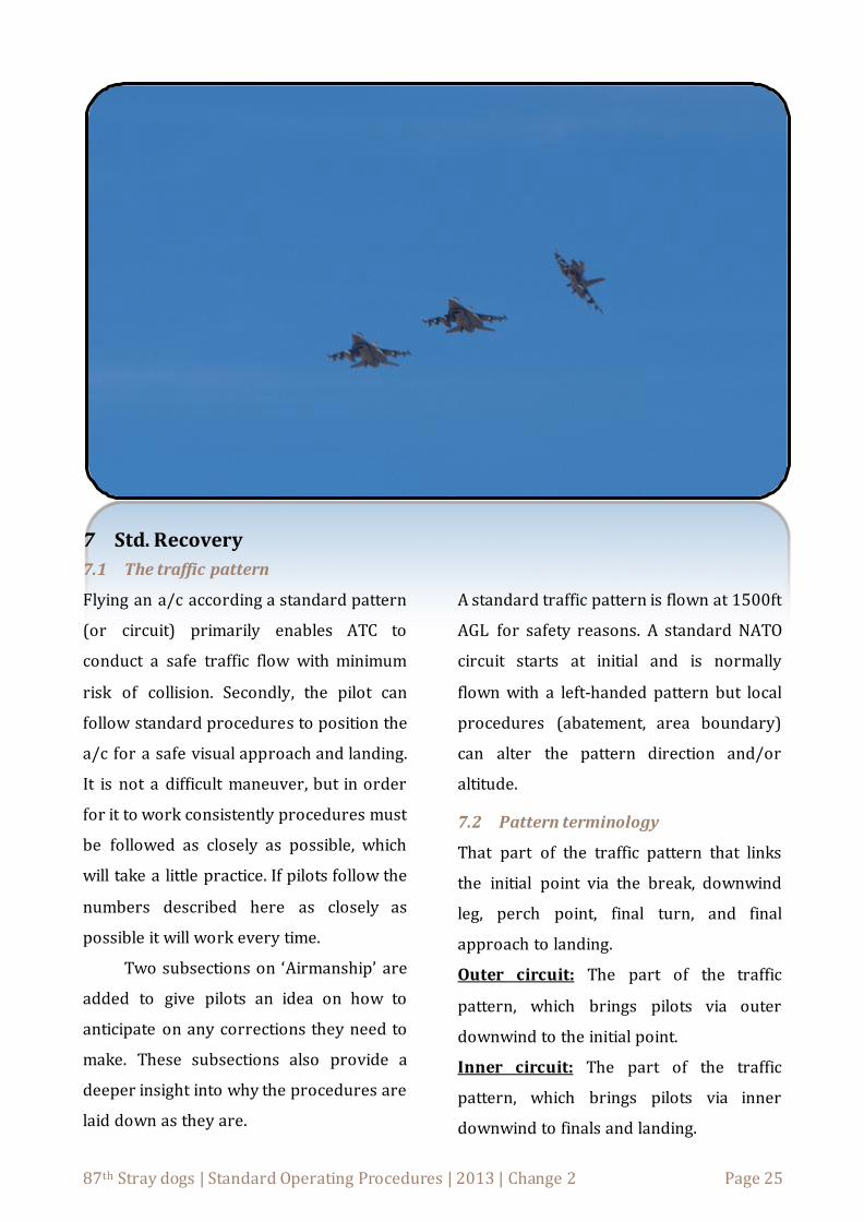
7 Std. Recovery
7.1 The traffic pattern
Flying an a/c according a standard pattern
(or circuit) primarily enables ATC to
conduct a safe traffic flow with minimum
risk of collision. Secondly, the pilot can
follow standard procedures to position the
a/c for a safe visual approach and landing.
It is not a difficult maneuver, but in order
for it to work consistently procedures must
be followed as closely as possible, which
will take a little practice. If pilots follow the
numbers described here as closely as
possible it will work every time.
Two subsections on ‘Airmanship’ are
added to give pilots an idea on how to
anticipate on any corrections they need to
make. These subsections also provide a
deeper insight into why the procedures are
laid down as they are.
A standard traffic pattern is flown at 1500ft
AGL for safety reasons. A standard NATO
circuit starts at initial and is normally
flown with a left-handed pattern but local
procedures (abatement, area boundary)
can alter the pattern direction and/or
altitude.
7.2 Pattern terminology
That part of the traffic pattern that links
the initial point via the break, downwind
leg, perch point, final turn, and final
approach to landing.
Outer circuit: The part of the traffic
pattern, which brings pilots via outer
downwind to the initial point.
Inner circuit: The part of the traffic
pattern, which brings pilots via inner
downwind to finals and landing.

87th Stray dogs | Standard Operating Procedures | 2013 | Change 2 Page 26
The initial point: A geographical position
normally ± 5 nm on the extended
centerline of the runway in use (Figure 10).
The break: Normally initiated over the
first third of the runway from which a
decelerating level turn to the downwind leg
is performed.
Downwind leg: The part of the inner
circuit which is parallel and opposite to the
runway in use, starting from the break to
the perch point.
Perch point: A point at the end of the
downwind leg from which the final turn is
started. It’s located abeam to 450 off the
threshold.
Final turn: A descending turn to position
the a/c wings level aligned with the
runway centerline.
Final Approach: From rolling wings level
to the landing.
Pilots should also be familiar with:
Go Around: Description of the action when
an approach is discontinued.
Touch & Go: Description of the action
when an a/c lands and takes off not
allowing the a/c to come to a complete
stop.
7.3 Execution
The procedures laid down will be
applicable to almost every situation.
However, the possibility exists that local
procedures dictate otherwise. So before
each flight, pilots should be familiar with
all the items concerning circuit flying i.e.
airfield elevation, runway in use, direction
of the traffic pattern, initial point
procedures, etc.
7.4 Joining the outer circuit
When returning from a sortie, decent to
10.000ft or below and contact tower at 30
nm from the intended field of recovery (see
mandatory reporting points later).
Subsequently, decent to 2000ft
(Above Aerodrome Level) and decelerate
to circuit airspeed of 300 KCAS. Before
within 8nm of the airfield report callsign
and state you are about to enter the CTR or
how long before you are about to (up to 1
minute is reasonable) and request
intended recovery. For example ‘Initial for
break’ or ‘Initial for straight in’ or ‘Long
final’
Join the outside downwind at 2000ft
above aerodrome level with 4 nm lateral
separation to the runway. Then turn to fly
over the initial point and continue onto the
inner circuit.
7.5 Joining the inner circuit
The initial point: Inform ATC at initials
and state intentions (see mandatory
reporting points later). Decent to 1500ft
and maintain 300 KCAS. Look for
significant ground features in the direction
of a/c wingtips and alongside of the airfield
to determine when to perform the break
and where to roll out.

87th Stray dogs | Standard Operating Procedures | 2013 | Change 2 Page 27
The break: Inform ATC at the break.
Maintain power setting for 300 KCAS in
straight and level flight (± 80% Ng RPM).
Roll to 700 angle of bank (AOB) and make a
level turn to downwind. During the turn
adjust AOB to roll out over the downwind
leg with wings level and parallel to the
runway.
Figure 10: The overhead break
Downwind leg: On inner downwind leg
pilots will be busy. Not only configuring
their a/c but also flying at the correct
heading, altitude and speed. Therefore use
the following continues check: (HDDS):
Height: (1500ft AGL).
Distance: Runway on wingtip.
Direction: Air for a distant aim point and
correct for wind.
Speed: Maintain 220KCAS
When stable on downwind, without delay
select gear down and add 2 – 5% Ng RPM
to maintain speed and correct nose
position to account for the aerodynamic
effects of the extension of gear and flaps.
Perch point: Approaching the end of the
runway, look over your shoulder and
determine when to roll into the perch. Start
the final turn from abeam to 450 off the
threshold.
Figure 11: Advised perch area
Final turn: Before rolling in for the final
turn select a point on the ground abeam of
the a/c in the runway’s extended centerline
to fly to and roll out over on final. So use
this point to plan the ground track to final.
Proceed as follows:
Inform ATC at base, with the gear down.
State intentions.
Press the nose to 00 pitch and roll
maximum 450 of bank.
Adjust bank during the turn to fly the
predicted ground track.

87th Stray dogs | Standard Operating Procedures | 2013 | Change 2 Page 28
Make sure the AoA stay’s below 130. Add
power to degrees AoA or correct altitude
loss and pitch to control speed.
Apply speed brakes as required (rule of
thumb open the breaks half way through
the turn).
Roll out over the extended centerline at
or above 30 glideslope.
Final Approach: Fly a 30 glide at 11 and 13
AoA. Perform final checks (3 green lights
and landing clearance obtained).
Correct speed with pitch.
Correct glide path with power.
Remember one item cannot be changed
without affecting the other. If pilots want to
climb back to the glide path, add power but
raise the nose to maintain speed and vice
versa.
Landing: Approach the runway threshold,
descending below 100ft, smoothly raise the
nose.
Fully extend the speed brakes.
Slowly reduce power.
Maintain pitch until 90 KCAS or below
then lower the nose wheel slowly to the
ground.
7.6 Mandatory Position Reports
Initial contact at 30DME:
“C/S, formation size, VFR or IFR and position (radial and DME, or FIX) with type of landing (intentions)
Initial point (5NM) :
"C/S, at initials, intentions"
Turning base:
“C/S, three greens, intentions”
7.7 Airmanship outer circuit
Since tactical cruise altitude are close to
20.000ft the pilot can use a 30 decent angle
starting at 60nm to end at 10.000ft at
30nm and even continue on that casual 30
decent to 2000ft which is also controllable
for formations and gives an economic glide
angle.
Descending to 2000ft initially will
give a 500ft vertical separation from a/c on
the ILS and in the traffic pattern, so pilots
could choose to overfly the airfield without
conflicting with other traffic.
The 4nm lateral spacing at outer
downwind is about the turn diameter an
aircraft needs for a level turn at 300 KTAS
with 450 of bank. Which is perfect for the
formation fighter turns in echelon.
7.8 Airmanship in the inner circuit
ATC needs a 4000ft horizontal spacing
between A/C. At 1500ft a ground track
4000ft away from the runway center lays
exactly on the wingtip, hence the visual
reference to the wingtips. A 700 of bank
with 300 KTAS = 4000ft turn diameter. As

87th Stray dogs | Standard Operating Procedures | 2013 | Change 2 Page 29
speed decreases bank also needs to be
decreased to maintain this number.
If the preceding a/c has not passed
the 3/9 o’clock position before your next
action you will not be able to maintain the
separation - break out and return to initial
or delay the next turn.
A good landing requires a good
approach. If the downwind, base and final
turns are sloppy chances are slim to make a
smooth final approach. Thus, if pilots get a
low-speed-warning, get low on altitude, or
turn either short or wide on the centerline
then GO ARROUND!
Look-out and listen. A great deal of
the time in the circuit must be spent on
looking outside for references and other
traffic. Listen to all radio calls to build
situational awareness through the position
reports.
Get comfortable in flying without the
HUD. Many (virtual) pilots rely on the HUD
and get disorientated when flying without.
No pilot learns how to fly with a HUD from
the start. Neither should virtual pilots.
7.9 Factors affecting the circuit
The circuit is considered to be a fixed
ground track from which minor position
deviations are allowed. These very small
deviations can be used in order to optimize
the final approach and landing. However,
the final approach speed and final
approach angle will depend on the aircraft
type, aircraft configuration and type of
approach. So consider the following:
Wind: The circuit should follow the same
path over the ground regardless of wind.
Therefore corrections need to be made to
compensate for drift. Especially strong
winds will affect the traffic pattern:
The bank angle in turns has to be
adjusted to avoid excessive drift.
The time flying on downwind will be less,
so there is less time available for
configuration changes.
On final, more power is generally needed
to maintain the correct glide path.
Turbulence is likely at higher wind
speeds or gusty winds.
Experience will soon make pilots aware of
the prevailing conditions and they will
learn to act accordingly.
7.10 Weight considerations
Performing the overhead break with an
aircraft heavier than 25000 pounds is
putting the control inputs on the limits
making it difficult to perform. A low speed
warning on the base and final is likely and
may require corrections which will
eventually force a go-around.

87th Stray dogs | Standard Operating Procedures | 2013 | Change 2 Page 30
To give an idea: An F-16 Block40 with 2
wing tanks and 4 AIM-120’s and 6000
pounds of fuel is approximately at a gross
weight of 25000 pound. if configured like
this or any heavier by fuel or weapons,
consider a straight in landing.
Related Documents