LaserSnake2 110128 Underwater Laser Cutting Phase 1 TWI-002 6-13

Welcome message from author
This document is posted to help you gain knowledge. Please leave a comment to let me know what you think about it! Share it to your friends and learn new things together.
Transcript
LaserSnake2 110128
Underwater Laser Cutting Phase 1
TWI-002 6-13
22883/2/13 TWI Ltd
Contents
1 Introduction 1
2 Objectives 1
3 Underwater Cutting Nozzle – Design and Operation 1
3.1 Design 1
3.2 Dry-zone testing 3
4 Equipment and Materials used in the Underwater Cutting Trials 5
5 Experimental Procedures – Underwater Cutting 5
6 Results 6
6.1 Underwater trials 6 6.1.1 Wedge shaped samples 6 6.1.2 Demonstration components 10
7 Discussion 11
8 Conclusions 12
9 Acknowledgements 12
10 Disclaimer 12 Table Figures 1-12

22883/2/13 1 TWI Ltd
1 Introduction
One of the key deliverables in the LaserSnake2 project is the development and assessment of an underwater laser cutting process. The desire and motivation for dismantling medium to high level nuclear waste underwater, is to significantly reduce contaminants escaping into the atmospheres and eliminate the logistics of handling and transporting such waste from the pond to the processing area. There is an increasing interest in the nuclear sector, particularly in the UK, to acquire an underwater cutting technology that could be versatile enough to both size reduce and decommission such waste. The primary benefits of dismantling nuclear waste underwater are to minimise production of secondary waste and reduce the complexity of remote operation. Currently, there are three underwater cutting technologies considered for dismantling structures in the nuclear industry: 1 Abrasive Water Jet: This technology is capable of cutting variety of materials, in varied
depths and in thick-sections but it is inherently slow and produces significant secondary waste in the form of contaminated abrasive.
2 Diamond Wire Sawing: This technology is frequently used by oil and gas industries for dismantling of extremely large structures and can be used at extreme depths. However, such machines are large, heavy and contain complicated mechanisms for traversing the wire. The cost of deployment, running and final decommissioning of such cutting systems in nuclear decommissioning operations restricts the use of this technology in this sector.
3 Plasma Arc: This technology has proven itself to be cheap and reliable in cutting metallic materials, but mostly on planner geometries and it is used by the nuclear industry as well as the oil and gas sector. However, its use is inherently limited by standoff distance and electrically conductive and flat material geometries. Furthermore, the process produces a high level of secondary waste, and requires frequent nozzle changes, increasing operational time and costs.
Laser technology, especially with recent development in fibre delivered beams, could offer a fourth choice to the nuclear industry. This report details the first phase of developments in underwater laser cutting nozzle design and the resulting process performance in cutting of thick-section C-Mn steel plates within the LaserSnake2 collaborative project. Because of the attenuation of fibre delivered laser light in water, the approach taken was to design a cutting nozzle that would create a ‘dry’ zone in the immediate area of the interaction of the laser beam with the material being cut.
2 Objectives
Design and manufacture an underwater laser cutting nozzle, capable of providing a ‘dry’ zone at the point of cutting.
Assess and characterise the operating performance of the underwater laser cutting nozzle, by identifying the maximum cut depth possible when using a 5kW continuous-wave (CW) fibre laser.
3 Underwater Cutting Nozzle – Design and Operation
3.1 Design
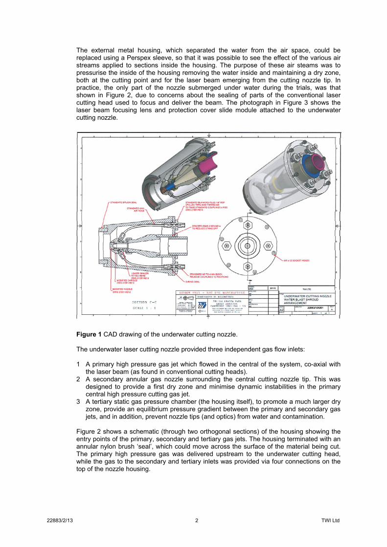
Figure 1 shows a CAD design of the underwater cutting nozzle attachment. This system was designed to fit round an existing 250mm focal length cutting head. The housing was designed so that the position of the nozzle tip of the cutting head could be moved up and down with respect to the external housing. This facility allowed changes to be made to the cutting nozzle tip to workpiece stand-off distance, without changing the position of the focusing laser beam. In this way, the beam focus position, with respect to the surface of the material, remained constant as the stand-off distance varied.
22883/2/13 2 TWI Ltd
The external metal housing, which separated the water from the air space, could be replaced using a Perspex sleeve, so that it was possible to see the effect of the various air streams applied to sections inside the housing. The purpose of these air steams was to pressurise the inside of the housing removing the water inside and maintaining a dry zone, both at the cutting point and for the laser beam emerging from the cutting nozzle tip. In practice, the only part of the nozzle submerged under water during the trials, was that shown in Figure 2, due to concerns about the sealing of parts of the conventional laser cutting head used to focus and deliver the beam. The photograph in Figure 3 shows the laser beam focusing lens and protection cover slide module attached to the underwater cutting nozzle.
Figure 1 CAD drawing of the underwater cutting nozzle. The underwater laser cutting nozzle provided three independent gas flow inlets: 1 A primary high pressure gas jet which flowed in the central of the system, co-axial with
the laser beam (as found in conventional cutting heads). 2 A secondary annular gas nozzle surrounding the central cutting nozzle tip. This was
designed to provide a first dry zone and minimise dynamic instabilities in the primary central high pressure cutting gas jet.
3 A tertiary static gas pressure chamber (the housing itself), to promote a much larger dry zone, provide an equilibrium pressure gradient between the primary and secondary gas jets, and in addition, prevent nozzle tips (and optics) from water and contamination.
Figure 2 shows a schematic (through two orthogonal sections) of the housing showing the entry points of the primary, secondary and tertiary gas jets. The housing terminated with an annular nylon brush ‘seal’, which could move across the surface of the material being cut. The primary high pressure gas was delivered upstream to the underwater cutting head, while the gas to the secondary and tertiary inlets was provided via four connections on the top of the nozzle housing.

22883/2/13 3 TWI Ltd
Figure 2 Underwater laser cutting process schematic. (Stand-off distance =15mm).
3.2 Dry-zone testing
The underwater housing was connected to a set of standard focusing optics; in this case the focusing lens used had a focal length of 250mm. This assembly can be seen in Figure 3. In order to assess the performance of the secondary and tertiary inputs to the underwater nozzle and their capability to form a dry-zone, a series of trials were performed without using assist gas in the primary central gas jet. These tests were performed in three configurations and with nothing beneath the nozzle. 1 All four inputs to the housing were connected to the secondary annular gas jet. The gas
to the four inputs was supplied with one common input to ensure equal gas pressure distribution. The whole underwater housing was lowered vertically into the water tank, and the cutting head was tilted to approximately 30o with respect to vertical axis to allow the housing to be partially filled with water. Gas pressure to the four 4mm diameter inputs was applied via a single 6mm id hose, split into four individual tubes. Several tests were performed in this configuration, varying the gas pressure between 0.5 and 6bar.
2 Two inputs to the housing were connected to the secondary annular gas jet and the remaining two, to the tertiary input to the nozzle housing. Similarly to test 1, the housing was lowered into the water tank without the primary central gas jet being pressurised, and the system was tested at similar gas pressures to test 1, while tilting the head to 30° to the vertical axis. Similarly to test 1, the housing was partially filled with water and the displacement of water level in the tertiary chamber was monitored for each gas pressure setting.

22883/2/13 4 TWI Ltd
3 The third test arrangement was identical to the second test, but with one exception, that being that the tertiary nozzle housing was first allowed to completely fill with water. This was achieved by disconnecting the two gas inputs to the tertiary chamber and displacing the trapped air in the chamber with water. After the chamber was full, the gas connections were re-attached and pressurised to measure the time to evacuate the water from the chamber.
In test 1, with no gas connection to the tertiary input, and with the nozzle in the vertical position, no change in the water level inside the tertiary chamber was noticed for changes in the secondary gas pressure. The water level was always maintained just above the brush seal. Gas pressure trials when the cutting head was tilted at the 30o position, showed a slight increase in the water level inside the chamber. When two gas inputs were connected in tests 2 and 3 configurations, it was found that a moderate pressure of 0.5bar was sufficient to displace the water from the chamber within 0.4 seconds and maintain a dry zone. However, better performance was seen at higher pressures up to 4bars. As a result, the configuration in test 2 was chosen for the underwater laser cutting trials detailed below. Figure 4 shows the underwater cutting head in test 2 mode (without the primary assist gas jet), showing an inverted ‘bell’ like air/water interface. Trials with the test 2 configuration were also carried out with the nozzle positioned on a workpiece. In this case, the bell like air/water interface disappeared and all gas was seen escaping the between the nylon brush seal and the workpiece surface. When activating the primary gas jet at 8 bar pressure, the gas escape route was still between the nylon brush and the workpiece surface, but with much higher turbulence.
Figure 3 Focusing lens assembly connected to the underwater cutting housing.

22883/2/13 5 TWI Ltd
Figure 4 Lower part of the underwater housing pressurised with air. The brush seal can be seen and a ‘bell’ like air/water interface. The secondary and the tertiary gas pressures were set to 4bar of compressed air pressure with no gas flow through the primary central gas jet.
4 Equipment and Materials used in the Underwater Cutting Trials
For the underwater laser cutting trials, the following equipment and materials were used: An underwater laser cutting nozzle/head assembly designed and developed by TWI, as
described above. A 1m3 volume water tank, with water level sufficient to ensure that the underwater
cutting nozzle was fully submerged. A JS30 Kawasaki robot to move the laser cutting head across the material surface in a
straight line. A laser capable of transmitting its power though a 0.15mm diameter delivery fibre,
which was coupled to the cutting head. The cutting head comprised of a 120mm collimating lens and a 250mm focusing lens,
and both these optics were protected from contamination by a cover slide. The gas fed through the primary jet was supplied by a high pressure hose connected to
a compressed air supply bank which contained 10 standard compressed cylinders. This high pressure assist gas was delivered through a 4mm diameter nozzle tip.
The gas to the secondary and the tertiary inputs was provided by a compressor, and for all cutting trials 4 bar pressure was maintained before the four inputs.
For the underwater cutting trials, samples from a 60mm thickness S355J2+N C-Mn steel plate, machined at 45 degrees were used.
For additional trials, a variable thickness, 6 to 12mm epoxy painted S275JR C-Mn steel plate and 20 and 35mm thickness S355J2+N C-Mn steel plates were used.
5 Experimental Procedures – Underwater Cutting
In order to minimise the number of cutting trials, a 60mm thickness S355J2+N C-Mn steel plate was flame cut into a 45o wedge. Simple linear cuts across the wedge shaped section, made with the laser beam axis pointing vertically downwards, (see Figure 5) were performed to assess the maximum cut depth attainable for cutting speeds ranging from 50 to 1000mm/min. For each cutting speed, the secondary and the tertiary gas supply was maintained at constant pressure of 4bar, whilst the primary central gas pressure (from now on referred to as the assist gas pressure) was varied between 2 and 8bar. In addition, for each combination of cutting speed and assist gas pressure, 4 stand-off distances (cutting nozzle tip to plate surface distance) were tested, ranging from 15 to 30mm. The standoff distance described here was between the tip of the primary gas jet and the workpiece, and was varied by introducing 5mm thickness spacers between the nozzle housing and the

22883/2/13 6 TWI Ltd
cutting nozzle. The standoff distance between end of the nylon brush and the workpiece was kept constant (~2mm) for all cutting trials. The emphasis in these experiments was to assess the effectiveness of the assist gas jet underwater. A constraint in the underwater cutting head design was the fixed laser focal position of 15mm above the material surface. For the 250mm focal length lens in use, this equates to a calculated laser beam diameter of 1.1mm on the material surface. In all the laser cutting trials, a constant laser power of 4.8kW was used and all cuts were performed with the samples at a water depth of 200mm.
The underwater cutting procedure consisted of first charging the secondary and the tertiary parts of the cutting head with compressed air at a pressure of 4bar, when the nozzle assembly was located outside the tank. This gas supply was provided from the compressor. This procedure was seen to maintain the dry zone and also kept all optical surfaces from splashing with water. The robot was first programmed to index the nozzle and the cutting head to the start position relative to the workpiece, ensuring the chosen distance between the brush seal and the workpiece was always maintained by pre-programming the robot movement and performing a simulated cut without the laser and the assist gas jet. Just before commencing the cutting process, the laser beam and the assist gas jet were activated. This procedure was repeated for each set of parameters. For each parameter set, kerf width and maximum cut depth were measured, and the data recorded. The list of experimental parameters and their range is shown in the Table. Table Underwater laser cutting parameters
Laser power 4.8kW Gas pressure 2, 4 and 8bar Cutting speeds 50 to 1000 mm/min Standoff distances 15 to 30mm Lens focal length 250mm Focal position +15mm
6 Results
6.1 Underwater trials
6.1.1 Wedge shaped samples
The assembly shown in Figure 3 was attached to a standard collimating unit and to the laser using a standard 150 micron diameter optical fibre. An example of linear cuts produced at different conditions on a 45o wedge plate, 60mm in thickness is shown Figure 5.
Figure 5 Linear cut tracks produced at standoff distance of 15mm for seven cutting speeds and two gas pressures.

22883/2/13 7 TWI Ltd
The maximum cut depths achieved with 4.8kW laser power, for 7 linear cutting speeds, 4 standoff distances, and 3 cutting/assist air pressures, are shown in Figures 6 to 8 respectively. A deeper cut depth was achieved at low cutting speed for all parameters and the cut depth exponentially decreased with increase in the cutting speed. There was no appreciable difference in maximum cut depths with variation in either the assist gas pressure or standoff distance, except when cutting at speeds below 200mm/min. A positive effect of the higher primary gas pressure of 8bar, on maximum cut depth, was observed for larger standoff distance but the increase in performance was relatively small. In all the cutting trials, use of a smaller standoff distance produced slightly deeper cut depth.
Figure 6 Maximum underwater cut depths achieved as a function cutting speed using 2bar assist gas pressure and 4.8kW of laser power, at four standoff distances.

22883/2/13 8 TWI Ltd
Figure 7 Maximum underwater cut depths achieved as a function of cutting speed using 4bar assist gas pressure and 4.8kW of laser power, at four standoff distances.
Figure 8 Maximum underwater cut depths achieved as a function of cutting speed using 8bar assist gas pressure and 4.8kW of laser power, at four standoff distances.
Kerf widths measured for all parameter sets are shown in Figures 9 to 11, for assist gas pressures of 2, 4 and 8bar respectively. Unlike for maximum cut depth results, considerable difference in the measured kerf widths was noticed as a function of standoff distance and assist gas pressures. Generally, a larger nozzle to workpiece stand-off distance produced a larger kerf width, even though the laser beam focal diameter on the material surface was always maintained constant at the value of 1.1mm. The maximum and minimum kerf widths recorded were 2.1 and 1.1mm. At 2bar assist gas pressure, the kerf width was found to

22883/2/13 9 TWI Ltd
linearly decrease with the cutting speed. However, increasing the cutting/assist gas pressure to 4 and 8bar, the relationship was noticed to change to an exponential profile as the cutting speed was increased. This effect was most noticeable when cutting with gas pressure of 8bar. The following general trends were noticed from examining the wedge shaped samples: Higher cutting speed produced a lower cut depth. The amount of dross attached at the bottom of the workpiece surface increased with cut
depth, and with lower cutting/assist (primary) gas jet pressure. Kerf widths measured for all conditions were between 1.1 and 2.1mm, and larger kerf
widths were seen when cutting at slow speeds.
Figure 9 Kerf width achieved as a function of cutting speed using 2bar air pressure and 4.8kW of laser power, at four standoff distances.

22883/2/13 10 TWI Ltd
Figure 10 Kerf width achieved as a function of cutting speed using 4bar air pressure and 4.8kW of laser power, at four standoff distances.
Figure 11 Kerf width achieved as a function of cutting speed using 8bar air pressure and 4.8kW of laser power, at four standoff of distances.
6.1.2 Demonstration components
For the demonstration components, three flat C-Mn steel plates, two with constant thicknesses of 20 and 35mm, and one with a variable thickness, from 6 to 12mm were chosen. Using the maximum cut depth results obtained for a primary gas pressure of 8bar and a standoff distance of 15mm in Figure 8, the corresponding expected cut depths and cutting speeds for each demonstrator were identified and chosen. Using these identified

22883/2/13 11 TWI Ltd
conditions all three materials were cut, and the sections of these underwater cut samples are shown in Figure 12.
Figure 12 Sections of underwater laser cut samples: a) Variable thickness (6 to 12mm) S275JR C-Mn steel plate cut at 500mm/min; b) 20mm thickness S355J2+N C-Mn steel plate cut at 200mm/min; c) 35mm thickness S355J2+N C-Mn steel plate cut at 50mm/min.
7 Discussion
Laser cutting of S275JR C-Mn steel in a dry environment were reported in LaserSnake1 (TP2643-24267), where maximum cutting speeds 1100mm/min and 300mm/min (using 4.8kW of laser power, 8bar assist gas pressure, a beam focal position located at the material surface and with a 250mm focal length lens) were achieved for material thicknesses of 12 and 25mm respectively. In comparison, (with the exception of beam focus position), the underwater cutting results indicated ~50% reduction in cutting speed (for an equivalent thickness). The cut quality achieved in the dry environment showed cleaner kerfs and less dross when compared with the underwater results. Particularly, a significant difference in the dross formation was noticed with the underwater cutting process.
The amount of dross attached at the kerf exit with underwater process was seen to increase with cut depth, and with lower cutting gas pressure. In decommissioning of nuclear materials, excess dross attachment to the cut sample may be desirable as this may lock in more contaminated material, which otherwise would discharge in the water, and thus result in reduced secondary waste Analysis of Figures 6 to 8 indicates that there was no appreciable difference in maximum cut depth with variations in the assist gas pressure, for all standoff distances evaluated. However, a slight increase in the cut depth was seen as a function of standoff distances at lower cutting speeds. This suggests that the gas flow inside the kerf is nearly the same for nearly all pressure conditions. This minimal difference in cutting performance was noticed between the two standoff distances of 15 and 30mm, but was found to be limited to cutting speeds below 200mm/min; a standoff distance of 15mm resulted in a higher cut depth, when the cutting speed was lower than 200mm/min. A positive effect of 8bar gas pressure on the maximum cut depth, was observed for larger standoff distance, but the increase in performance was relatively small (0.5% to 7% for a 15mm standoff, and 4% to 17% for a standoff of 30mm, between 8 and 2bar assist gas pressures). In this work, generally higher assist gas pressure produced smaller kerf widths and the largest kerf width was produced with the higher standoff distance of 30mm, even though the focal position was experimentally the same for all cutting conditions. This may indicate a variation in the laser beam diameter (laser power intensity) on the material surface due to possible variations in the refractive index of a mixed phase (water vapour (steam) & air) medium inside the kerf width. Nevertheless, one would normally expect a higher contrast in cut depths as a function of standoff distance, because of the variation in the kerf width
a)
b)
c)

22883/2/13 12 TWI Ltd
seen. This was not noticed and may be due to insufficient gas jet momentum produced by use of only 2bar assist gas pressure. It is also likely that material removal rate was higher with the 8bar assist gas pressure, but due to convection cooling from the water, the ejected material solidified as dross inside and at the end of the narrow kerf exit, requiring additional laser energy for complete break through. The relationship between kerf width, assist gas pressure, cutting speed and cut depth, requires addressing in more detail, by taking into account the additional parameter of beam focal position, in future underwater cutting trials.
8 Conclusions
Experimental trials performed with the prototype nozzle have allowed the following conclusions to be drawn: An underwater laser cutting nozzle has been designed, manufactured and tested, which
showed good potential for creating and maintaining during cutting, of a dry-zone on the material surface.
Using the laser power available, the maximum cut depth in S355J2+N C-Mn steel was 38mm. This was achieved at a travel speed of 50mm/min.
Higher cut depth was achieved with a slower cutting speed and increased cut depths produced larger attached dross volume at the kerf exit. The attached dross volume was also seen to increase when cutting with lower assist gas pressure
Assist gas pressure had very little effect on the maximum cut depth for most standoff distances, but a slight increase in performance with 8bar assist gas pressure was observed when cutting with the larger standoff distances.
Variations in kerf width were more noticeable than variations in the maximum cut depth. At higher assist gas pressure, a larger kerf width allowed more gas to escape through the laser cut channel, resulting in a slight increase in the cut depth.
The present underwater prototype nozzle design was found to be quite insensitive to assist gas pressure or standoff distance, over the range of values used in these experiments. This indicates that modest assist gas pressures will be able to produce reasonable underwater cutting performance, which will be a very desirable requirement when laser cutting contaminated material underwater.
9 Acknowledgements
The author would like to thank Frank Nolan who conducted the cutting trials. LaserSnake2 is co-funded by the Technology Strategy Board, the Department of Energy and Climate Change, and the Nuclear Decommissioning Authority, under grant number 110128.
10 Disclaimer
The data and results contained within this report are advisory in nature, expressed as an opinion only and no warranty, expressed or implied, is given as to the suitability of such advice or results for any particular purpose. The information made available by TWI Ltd over the World Wide Web does not form part of any contract. Whilst every effort has been made to ensure the accuracy of the information presented, TWI Ltd cannot accept responsibility for any errors.
Related Documents