LISA Laser Interferometer Space Antenna A proposal in response to the ESA call for L3 mission concepts Lead Proposer Prof. Dr. Karsten Danzmann

Welcome message from author
This document is posted to help you gain knowledge. Please leave a comment to let me know what you think about it! Share it to your friends and learn new things together.
Transcript
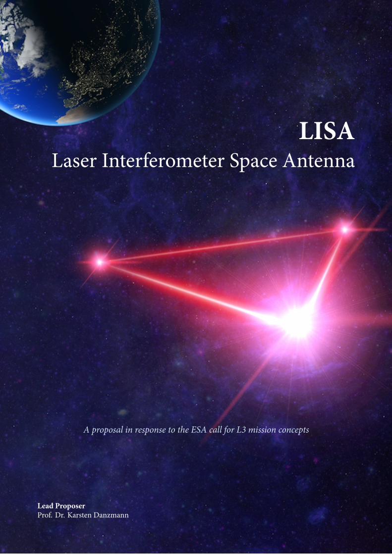
LISALaser Interferometer Space Antenna
A proposal in response to the ESA call for L3 mission concepts
Lead ProposerProf. Dr. Karsten Danzmann
Lead Proposer
Prof. Dr. Karsten Danzmann [email protected]
Will be available with at least 20% of his time to support the study activities throughout the study.
Albert Einstein Institute HannoverLeibniz Universität Hannover and Max Planck Institute for Gravitational PhysicsCallinstr. 38, D-30167 Hannover, Germany
Core Team
Pau Amaro-Seoane [email protected], Heather Audley [email protected], Stanislav Babak [email protected],John Baker [email protected], Enrico Barausse [email protected], Peter Bender [email protected],Emanuele Berti [email protected], Pierre Binetruy [email protected], Michael [email protected], Daniele Bortoluzzi [email protected], Jordan [email protected], Chiara Caprini [email protected], Vitor Cardoso [email protected],Monica Colpi [email protected], John Conklin [email protected], Neil [email protected], Curt Cutler [email protected], Karsten [email protected], Rita Dolesi [email protected], Luigi Ferraioli [email protected],Valerio Ferroni [email protected], Ewan Fitzsimons [email protected], Jonathan [email protected], Lluis Gesa Bote [email protected], Domenico Giardini [email protected],Ferran Gibert [email protected], Catia Grimani [email protected], Hubert [email protected], Gerhard Heinzel [email protected], Thomas [email protected], Martin Hewitson [email protected], Kelly [email protected], Daniel Hollington [email protected], Mauro Hueller [email protected],Henri Inchauspe [email protected], Philippe Jetzer [email protected], Nikos Karnesis [email protected],Christian Killow [email protected], Antoine Klein [email protected], Bill [email protected], Natalia Korsakova [email protected], Shane L [email protected], Jeffrey Livas [email protected], Ivan Lloro [email protected], Nary [email protected], Davor Mance [email protected], Joseph Martino [email protected], Ignacio [email protected], Kirk McKenzie [email protected], Sean T McWilliams [email protected],Cole Miller [email protected], Guido Mueller [email protected], Germano Nardini [email protected],Gijs Nelemans [email protected], Miquel Nofrarias [email protected], Antoine [email protected], Paolo Pivato [email protected], Eric Plagnol [email protected], Ed [email protected], Jens Reiche [email protected], David Robertson [email protected],Norna Robertson [email protected], Elena Rossi [email protected], Giuliana [email protected], Bernard Schutz [email protected], Alberto Sesana [email protected],David Shoemaker [email protected], Jacob Slutsky [email protected], Carlos F. [email protected], Tim Sumner [email protected], Nicola Tamanini [email protected], Ira [email protected], Michael Troebs [email protected], Michele [email protected], Alberto Vecchio [email protected], Daniele Vetrugno [email protected],Stefano Vitale [email protected], Marta Volonteri [email protected], Gudrun Wanner [email protected],Harry Ward [email protected], Peter Wass [email protected], William [email protected], John Ziemer [email protected], Peter Zweifel [email protected]
Consortium Members More than 300 scientists https://www.lisamission.org/consortium/Supporters More than 1300 researchers https://www.lisamission.org/supporters/
Typeset: February 20, 2017
Page 2 LISA –
Contents1 Introduction 6
2 Science performance 72.1 SO1: Study the formation and evolution of compact binary stars in the Milky Way Galaxy. . . . . 82.2 SO2: Trace the origin, growth and merger history of massive black holes across cosmic ages . . . 82.3 SO3: Probe the dynamics of dense nuclear clusters using EMRIs . . . . . . . . . . . . . . . . . . . 102.4 SO4: Understand the astrophysics of stellar origin black holes . . . . . . . . . . . . . . . . . . . . 112.5 SO5: Explore the fundamental nature of gravity and black holes . . . . . . . . . . . . . . . . . . . 112.6 SO6: Probe the rate of expansion of the Universe . . . . . . . . . . . . . . . . . . . . . . . . . . . . 122.7 SO7: Understand stochastic GW backgrounds and their implications for the early Universe and
TeV-scale particle physics . . . . . . . . . . . . . . . . . . . . . . . . . . . . . . . . . . . . . . . . . . 122.8 SO8: Search for GW bursts and unforeseen sources . . . . . . . . . . . . . . . . . . . . . . . . . . 132.9 Summary . . . . . . . . . . . . . . . . . . . . . . . . . . . . . . . . . . . . . . . . . . . . . . . . . . . 13
3 Mission Profile 143.1 Orbit . . . . . . . . . . . . . . . . . . . . . . . . . . . . . . . . . . . . . . . . . . . . . . . . . . . . . . 143.2 Launcher . . . . . . . . . . . . . . . . . . . . . . . . . . . . . . . . . . . . . . . . . . . . . . . . . . . 153.3 Concept of Operations . . . . . . . . . . . . . . . . . . . . . . . . . . . . . . . . . . . . . . . . . . . 153.4 Mission Lifetime . . . . . . . . . . . . . . . . . . . . . . . . . . . . . . . . . . . . . . . . . . . . . . . 163.5 Communication requirements and strategy . . . . . . . . . . . . . . . . . . . . . . . . . . . . . . . 16
4 Model Payload 164.1 Description of the measurement technique . . . . . . . . . . . . . . . . . . . . . . . . . . . . . . . 164.2 Key measurement performance requirement . . . . . . . . . . . . . . . . . . . . . . . . . . . . . . 174.3 Payload conceptual design and key characteristics . . . . . . . . . . . . . . . . . . . . . . . . . . . 184.4 Interferometry Measurement System (IMS) . . . . . . . . . . . . . . . . . . . . . . . . . . . . . . . 184.5 Gravitational Reference Sensor . . . . . . . . . . . . . . . . . . . . . . . . . . . . . . . . . . . . . . 204.6 Performance assessment with respect to science objectives . . . . . . . . . . . . . . . . . . . . . . 214.7 Resources: mass, volume, power, on board data processing, data handling and telemetry . . . . . 214.8 Payload control, operations and calibration requirements . . . . . . . . . . . . . . . . . . . . . . . 21
5 System Requirements & Spacecraft Key Factors 225.1 System Requirements . . . . . . . . . . . . . . . . . . . . . . . . . . . . . . . . . . . . . . . . . . . . 225.2 Spacecraft Key Factors . . . . . . . . . . . . . . . . . . . . . . . . . . . . . . . . . . . . . . . . . . . 225.3 S/C Concept . . . . . . . . . . . . . . . . . . . . . . . . . . . . . . . . . . . . . . . . . . . . . . . . . 245.4 Budgets . . . . . . . . . . . . . . . . . . . . . . . . . . . . . . . . . . . . . . . . . . . . . . . . . . . . 24
6 Science Operations and Archiving 27
7 Technology Development Requirements 297.1 Algorithms/ methodology / simulation / data processing . . . . . . . . . . . . . . . . . . . . . . . 29
8 Management Scheme and Cost Analysis 308.1 LISA Consortium Organisation, Roles and Responsibilities . . . . . . . . . . . . . . . . . . . . . . 328.2 Payload and Instrument Description . . . . . . . . . . . . . . . . . . . . . . . . . . . . . . . . . . . 348.3 International Partners . . . . . . . . . . . . . . . . . . . . . . . . . . . . . . . . . . . . . . . . . . . . 358.4 Preliminary Program Schedule . . . . . . . . . . . . . . . . . . . . . . . . . . . . . . . . . . . . . . 368.5 Preliminary Cost Analysis . . . . . . . . . . . . . . . . . . . . . . . . . . . . . . . . . . . . . . . . . 368.6 Risk analysis . . . . . . . . . . . . . . . . . . . . . . . . . . . . . . . . . . . . . . . . . . . . . . . . . 37
9 Conclusion 38
LISA – CONTENTS Page 3
Executive Summary
The last century has seen enormous progress in our un-derstanding of the Universe. We know that the Uni-verse has emerged from the big bang, has been expand-ing at large, and contains luminous baryonic structuresthat shape our cosmic landscape. We know that starsare continuing to form in galaxies, and that galaxiesform and assemble along filaments of the cosmic web.Powerful quasars and gamma-ray bursts were alreadyin place when the Universe was less than one billionyears old, indicating places where the first black holesformed. By using electromagnetic radiation as a toolfor observing the Universe, we have learned that fluc-tuations at early epochs seeded the formation of all cos-mic structures we see today. However, we do not knowthe nature of this dark component, which is revealedthrough its gravitational action on the luminous mat-ter, nor how, when, and where the first black holesformed in dark matter halos.We have come remarkably far using electromagneticradiation as our tool for observing the Universe. How-ever, gravity is the engine behindmany of the processesin the Universe, and its action on all forms of massand energy is dark. But gravity has its own messenger:Gravitational Waves, ripples in the fabric of spacetime,which travel essentially undisturbed from the momentof their creation. Observing Gravitational Waves fromcosmic sources will let us explore a Universe inacces-sible otherwise, a Universe where gravity takes on newand extreme manifestations.The groundbreaking discovery of Gravitational Wavesby ground-based laser interferometric GravitationalWave observatories in 2015 is changing astronomy,giving us access to the high-frequency regime of Grav-itational Wave astronomy. This is the realm of stellarmass objects at low redshift. Over the coming years, asthe sensitivity of ground-based detectors improves, wewill see the growth of a rich and productive Gravita-tional Wave astronomy. New sources with small masswill be discovered in the low redshiftUniverse. Alreadythe first observation of Gravitational Waves brought asurprise, because the existence of such heavy stellar-origin binary black holes was not widely expected. Butthe low-frequency window below one Hertz will prob-ably never be accessible from the ground. It is in thiswindow that we expect to observe the heaviest andmost diverse objects. Opening a gravitational windowon the Universe in the low-frequency regime with thespace-based detector LISA will let us go further thanany alternative. These low-frequency waves let us peerdeep into the formation of the first seed black holes, ex-
ploring redshifts larger than z ∼ 20prior to the epoch ofcosmic re-ionisation, and examining systems of blackholes with masses ranging from a few M⊙ to 108M⊙.Exquisite and unprecedented measurements of blackhole masses and spins will make it possible to trace thehistory of black holes across all stages of galaxy evolu-tion, and at the same time test the General-Relativisticnature of black holes through detailed study of the am-plitude and phase of the waveforms of GravitationalWave strain. LISAwill be the first evermission to studythe entire Universe with Gravitational Waves.LISA is an all-sky monitor and will offer a wide viewof a dynamic cosmos using Gravitational Waves asnew and uniquemessengers to unveilTheGravitationalUniverse. It provides the closest ever view of the infantUniverse at TeV energy scales, has known sources inthe form of verification binaries in the Milky Way, andcan probe the entire Universe, from its smallest scalesnear the horizons of black holes, all the way to cosmo-logical scales. The LISA mission will scan the entiresky as it follows behind the Earth in its orbit, obtainingboth polarisations of the Gravitational Waves simulta-neously, and will measure source parameters with as-trophysically relevant sensitivity in a band from below10−4 Hz to above 10−1 Hz.The LISA mission is proposed by an international col-laboration of scientists called the LISA Consortium.Our proposal is fully compliant with the science goalsindicated in the “Report of the Senior Survey Commit-tee on the selection of the science themes for the L2and L3 launch opportunities in the Cosmic Vision Pro-gramme”. The team builds upon the proto-consortiumthat proposed a GravitationalWave observatory for theL1 flight opportunity, and has been growing consider-ably ever since. It is augmented by additional memberstates and the US as an international partner. The LISAConsortium also proposed The Gravitational Universeas a science theme for the selection of the L2 andL3 launch opportunities and submitted the pertinentWhite Paper. The LISA Consortium also comprisesall the investigators who have successfully pursued theLISA Pathfinder mission, a number of scientists whoworked on the ground-based LIGO, Virgo, and GEOprojects, and the Laser Ranging Interferometer on theGRACE Follow-Onmission, thusmaking full use of allthe expertise that has accumulated. This approach op-timises the utilisation of the remaining time for mis-sion preparation and technology development. We ex-pect all mission elements to be at least at TRL 6 around2020.
Page 4 LISA – CONTENTS
The LISA mission will be based on laser interferom-etry between free flying test masses inside drag-freespacecraft. These test masses, contained within theGravitational Reference Sensors and effectively iden-tical to the ones flown on LISA Pathfinder, will followtheir geodesic trajectories with sub femto-g/
√Hz spu-
rious acceleration. Two testmasses free-fall inside eachspacecraft, with each one serving as a geodesic refer-ence end mirror for a single arm of the interferometer.The spacecraft is forced to follow the two test massesalong each of the two interferometry axes they define,based on local interferometric position readouts. Thetest masses are then electrostatically suspended to thespacecraft along the other degrees of freedom, con-trolled by a combination of interferometric and capac-itive position readouts. This system was successfullytested in the LISA Pathfinder mission, and this pro-vides the confident basis for the acceleration perfor-mance of the mission.The observatory will be based on three arms with sixactive laser links, between three identical spacecraft ina triangular formation separated by 2.5 million km.Continuously operating heterodyne laser interferome-ters measure with pm/
√Hz sensitivity in both direc-
tions along each arm, using well-stabilized lasers at1064 nm delivering 2W of power to the optical system.Again, using technology proven in LISA Pathfinder,the Interferometry Measurement System is using op-tical benches in each spacecraft. They will be con-structed from an ultra-low expansion glass-ceramic tominimize optical pathlength changes due to temper-ature fluctuations. 30 cm telescopes transmit and re-ceive the laser light to and from the other spacecraft.Three independent interferometric combinations ofthe light travel time between the test masses are pos-sible, allowing, in data processing on the ground, thesynthesis of two virtualMichelson interferometers plusa third null-stream, or “Sagnac” configuration.The Consortium will deliver to ESA the integrated sci-ence instrument at the heart of the payload, plus severalspacecraft-mounted parts of the instrument. It is ex-pected that the remaining parts of the payload, in par-ticular lasers and telescopes, will be procured byESAorprovided byNASA.The recommended option for LISAis to use one of the Ariane 6 family of launch vehicles,with a dedicated Ariane 6.4 launch being the preferredoption. With a launch capacity directly into an escapetrajectory of 7,000 kg, the Ariane 6.4 is very well suitedto the LISA launch requirements into the LISA refer-
ence orbit, which is a stable Earth-trailing heliocentricorbit about 50 million km from Earth, with a meaninter-spacecraft separation of 2.5 million km. This ref-erence orbit is optimised to minimise the key variableparameters of arm breathing angle and range rate be-tween the spacecraft, as both of these drive the com-plexity of the payload design, while at the same timeensuring that the distance to the constellation is suffi-ciently small for communication purposes.The entire constellation is expected to produce about35 kbit/s of data in the nominal science mode, leadingto a daily total of 334MB.We augment the bidirectionallaser links between the spacecraft with data links bymodulating data onto the pseudo-random code usedfor ranging. Ground communication can then takeplace with only one of the three spacecraft per pass andstill serve the whole constellation. With this configu-ration, for a single pointing of one antenna, commu-nications can be maintained with a single ground sta-tion for 3 days at a user data rate of > 108.5 kbps for 7.2hours of contact time per day using X band. This al-lows the re-pointing of the spacecraft antenna to hap-pen once every 9 days (by cycling through the constel-lation), while still enabling daily communications withLISA to minimise data latency.We propose a nominal mission duration of 4 years inscience mode. However, the mission should be de-signed with consumables and orbital stability to facili-tate a total mission of up to 10 years.By 2030 our understanding of the Universe willhave been dramatically improved by new observationsof cosmic sources through the detection of electro-magnetic radiation and high-frequency GravitationalWaves. Adding a low-frequency Gravitational Waveobservatory will complement our astrophysical knowl-edge by using our new sense to ‘hear’ with low-frequency Gravitational Waves, providing access to apart of the Universe that will forever remain invisiblewith light. LISA will be the first ever mission to sur-vey the entire Universe with Gravitational Waves. Itwill allow us to investigate the formation of binary sys-tems in the Milky Way, detect the guaranteed signalsfrom the verification binaries, alert astronomers of theimminent merger of heavy stellar-origin black holes,study the history of the Universe out to redshifts be-yond z = 20, test gravity in the dynamical strong-fieldregime with unprecedented precision, and probe theearly Universe at TeV energy scales. LISA will play aunique role in the scientific landscape of the 2030s.
LISA – CONTENTS Page 5
1 Introduction
The groundbreaking discovery of Gravitational Waves(GWs) by ground-based laser interferometric detec-tors in 2015 is changing astronomy [1] by openingthe high-frequency gravitational wave window to ob-serve low mass sources at low redshift. The SeniorSurvey Committee (SSC) [2] selected the L3 sciencetheme, The Gravitational Universe [3], to open the 0.1to 100mHz Gravitational Wave window to the Uni-verse. This low-frequency window is rich in a varietyof sources that will let us survey the Universe in a newand unique way, yielding new insights in a broad rangeof themes in astrophysics and cosmology and enablingus in particular to shed light on two key questions: (1)How, when and where do the first massive black holesform, grow and assemble, and what is the connectionwith galaxy formation? (2) What is the nature of grav-ity near the horizons of black holes and on cosmologi-cal scales?We propose the LISA mission in order to respond tothis science theme in the broadest way possible withinthe constrained budget and given schedule. LISA en-ables the detection of GWs from massive black holecoalescences within a vast cosmic volume encompass-ing all ages, from cosmic dawn to the present, acrossthe epochs of the earliest quasars and of the rise ofgalaxy structure. The merger-ringdown signal of theseloud sources enables tests of Einstein’s General Theoryof Relativity (GR) in the dynamical sector and strong-field regime with unprecedented precision. LISA willmap the structure of spacetime around the massiveblack holes that populate the centres of galaxies usingstellar compact objects as test particle-like probes. Thesame signals will also allow us to probe the populationof these massive black holes as well as any compact ob-jects in their vicinity. A stochastic GW background orexotic sources may probe new physics in the early Uni-verse. Added to this list of sources are the newly discov-ered LIGO/Virgo heavy stellar-origin black hole merg-ers, whichwill emitGWs in the LISAband from severalyears up to a week prior to their merger, enabling coor-dinated observations with ground-based interferome-ters and electromagnetic telescopes. The vast majorityof signals will come from compact galactic binary sys-tems, which allow us to map their distribution in theMilky Way and illuminate stellar and binary evolution.LISA builds on the success of LISA Pathfinder(LPF) [4], twenty years of technology development,and the Gravitational Observatory Advisory Team(GOAT) recommendations. LISA will use three arms
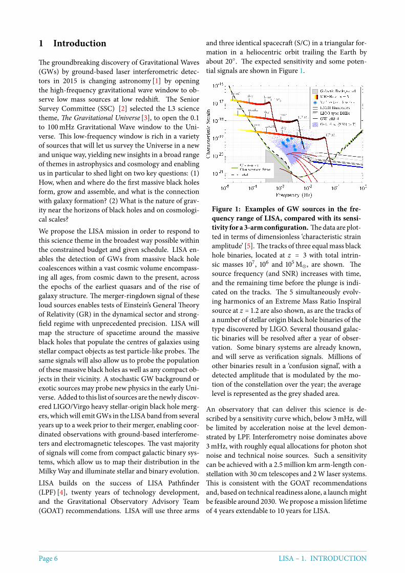
and three identical spacecraft (S/C) in a triangular for-mation in a heliocentric orbit trailing the Earth byabout 20. The expected sensitivity and some poten-tial signals are shown in Figure 1.
Figure 1: Examples of GW sources in the fre-quency range of LISA, compared with its sensi-tivity for a 3-armconfiguration. Thedata are plot-ted in terms of dimensionless ‘characteristic strainamplitude’ [5]. The tracks of three equalmass blackhole binaries, located at z = 3 with total intrin-sic masses 107, 106 and 105M⊙, are shown. Thesource frequency (and SNR) increases with time,and the remaining time before the plunge is indi-cated on the tracks. The 5 simultaneously evolv-ing harmonics of an Extreme Mass Ratio Inspiralsource at z = 1.2 are also shown, as are the tracks ofa number of stellar origin black hole binaries of thetype discovered by LIGO. Several thousand galac-tic binaries will be resolved after a year of obser-vation. Some binary systems are already known,and will serve as verification signals. Millions ofother binaries result in a ‘confusion signal’, with adetected amplitude that is modulated by the mo-tion of the constellation over the year; the averagelevel is represented as the grey shaded area.
An observatory that can deliver this science is de-scribed by a sensitivity curve which, below 3mHz, willbe limited by acceleration noise at the level demon-strated by LPF. Interferometry noise dominates above3mHz, with roughly equal allocations for photon shotnoise and technical noise sources. Such a sensitivitycan be achieved with a 2.5million km arm-length con-stellation with 30 cm telescopes and 2W laser systems.This is consistent with the GOAT recommendationsand, based on technical readiness alone, a launchmightbe feasible around 2030. We propose amission lifetimeof 4 years extendable to 10 years for LISA.
Page 6 LISA – 1. INTRODUCTION
2 Science performance
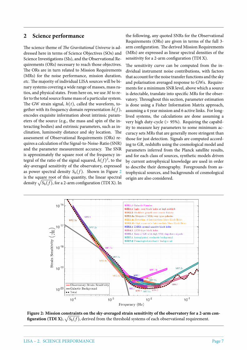
The science theme of The Gravitational Universe is ad-dressed here in terms of Science Objectives (SOs) andScience Investigations (SIs), and the Observational Re-quirements (ORs) necessary to reach those objectives.The ORs are in turn related to Mission Requirements(MRs) for the noise performance, mission duration,etc. The majority of individual LISA sources will be bi-nary systems covering a wide range of masses, mass ra-tios, and physical states. From here on, we use M to re-fer to the total source framemass of a particular system.The GW strain signal, h(t), called the waveform, to-gether with its frequency domain representation h( f ),encodes exquisite information about intrinsic param-eters of the source (e.g., the mass and spin of the in-teracting bodies) and extrinsic parameters, such as in-clination, luminosity distance and sky location. Theassessment of Observational Requirements (ORs) re-quires a calculation of the Signal-to-Noise-Ratio (SNR)and the parameter measurement accuracy. The SNRis approximately the square root of the frequency in-tegral of the ratio of the signal squared, h( f )2, to thesky-averaged sensitivity of the observatory, expressedas power spectral density Sh( f ). Shown in Figure 2is the square root of this quantity, the linear spectraldensity
√Sh( f ), for a 2-arm configuration (TDI X). In
the following, any quoted SNRs for the ObservationalRequirements (ORs) are given in terms of the full 3-arm configuration. The derived Mission Requirements(MRs) are expressed as linear spectral densities of thesensitivity for a 2-arm configuration (TDI X).The sensitivity curve can be computed from the in-dividual instrument noise contributions, with factorsthat account for the noise transfer functions and the skyand polarisation averaged response to GWs. Require-ments for a minimum SNR level, above which a sourceis detectable, translate into specific MRs for the obser-vatory. Throughout this section, parameter estimationis done using a Fisher Information Matrix approach,assuming a 4 year mission and 6 active links. For long-lived systems, the calculations are done assuming avery high duty-cycle (> 95%). Requiring the capabil-ity to measure key parameters to some minimum ac-curacy sets MRs that are generally more stringent thanthose for just detection. Signals are computed accord-ing to GR, redshifts using the cosmological model andparameters inferred from the Planck satellite results,and for each class of sources, synthetic models drivenby current astrophysical knowledge are used in orderto describe their demography. Foregrounds from as-trophysical sources, and backgrounds of cosmologicalorigin are also considered.
Figure 2: Mission constraints on the sky-averaged strain sensitivity of the observatory for a 2-arm con-figuration (TDI X),
√Sh( f ), derived from the threshold systems of each observational requirement.
LISA – 2. SCIENCE PERFORMANCE Page 7
2.1 SO1: Study the formation and evolutionof compact binary stars in the Milky WayGalaxy.
Numerous compact binaries in the Milky Way galaxyemit continuous and nearly monochromatic GW sig-nals in the source frame [6]. These Galactic Binaries(GBs) comprise primarily white dwarfs but also neu-tron stars and stellar-origin black holes in various com-binations. For those systems that can be detected, theorbital periods P = 2/ f can often be measured to highaccuracy. The orbital motion of the detector impartsa characteristic frequency and amplitude modulationthat allows us to constrain the extrinsic properties ofsome of the systems. Higher frequency systems aretypically louder and better characterized than low fre-quency systems. At low frequencies, GBs are thought tobe so numerous that individual detections are limitedby confusion with other binaries yielding a stochasticforeground or confusion signal. Several “verification”binaries are currently known for which joint gravita-tional and electromagnetic (EM) observations can bedone and many more will be discovered in the comingyears, e.g., by Gaia and LSST. Using the current bestestimate for the population [7], and assuming the ref-erence sensitivity, it should be possible to detect andresolve ∼ 25, 000 individual GBs.
SI1.1: Elucidate the formation and evolution of GBsby measuring their period, spatial and massdistributions.
OR 1.1.a: To survey the period distribution of GBs,and have the capability to distinguish between ∼ 5000systems with inferred period precision δP/P < 10−6.
OR 1.1.b: To measure the mass, distance and sky lo-cation for the majority of these GBs with frequencyf > 3mHz, chirp mass > 0.2M⊙ and distance < 15 kpc.
OR 1.1.c: To detect the low frequency galactic confu-sion noise in the frequency band from 0.5 to 3mHz.In Figure 2, the galactic confusion signal for a fiducialpopulation is shown assuming a 4 year observation af-ter subtraction of individual sources.
MR1.1: The ORs pose requirements in the band fromabout 0.5 mHz to 30mHz. OR 1.1b demands that thesensitivity for frequencies 3 mHz < f < 30 mHz has√Sh( f ) < 9 × 10⁻²¹( f /mHz)2/3. For the frequency
band indicated, this corresponds to having a strain sen-sitivity better than 1.2 × 10⁻²⁰Hz−1/2 at 3mHz, and7.8 × 10−20Hz−1/2 at 30mHz. From OR1.1.c, the iden-tification of the low frequency galactic confusion sig-nal requires us to be able to subtract all the identified/-
known sources with a certain precision which is lim-ited by the other unknown sources as well as the de-tector sensitivity. In order for the detector sensitivitynot to limit this significantly, we require the detectornoise level below 2mHz to be at, or below, the com-bined signal from galactic binaries. Using a conserva-tive estimate for the galactic population sets a limit onthe sensitivity in the band 0.5mHz < f < 3mHz givenby√Sh( f ) < 2.7 × 10⁻¹⁹ ( f /mHz)−11/6. For the band
discussed here, this corresponds to having a strain sen-sitivity better than 8.7 × 10⁻¹⁹Hz−1/2 at 0.5mHz, and3.2 × 10−20Hz−1/2 at 3mHz.
SI1.2: Enable joint gravitational andelectromagnetic observations of GBs to study theinterplay between gravitational radiation and tidaldissipation in interacting stellar systems.
OR 1.2.a: To detect ∼ 10 of the currently knownverification binaries, inferring periods with accuracyδP/P < 10−6.
OR 1.2.b: To enable identification of possible electro-magnetic counterparts, determine the sky location of∼ 500 systems within one square degree.
OR 1.2.c: To study the interplay between gravitationaldamping, tidal heating, and to perform tests of GR, lo-calise ∼ 100 systems within one square degree and de-termine their first period derivative to a fractional ac-curacy of 10% or better.
MR1.2: OR’s 1.1.a, 1.1.b and 1.2.b,c set requirementson the mission duration in order to achieve the desiredmeasurement precision. These requirements may notbe fully met for mission durations less than 4 years.
2.2 SO2: Trace the origin, growth and mergerhistory of massive black holes acrosscosmic ages
The origin of Massive Black Holes (MBHs) poweringactive nuclei and lurking at the centres of today’s galax-ies is unknown. Current studies predict masses fortheir seeds in the interval between about 103M⊙, anda few 105M⊙ and formation redshifts 10 ≲ z ≲ 15 [8].They then grow up to 108M⊙ and more by accretionepisodes, and by repeated merging, thus participatingin the clustering of cosmic structures [9], inevitablycrossing the entire LISA frequency spectrum, from afew 10−5 Hz to 10−1 Hz, since their formation redshift.Mergers and accretion influence their spins in differ-ent ways thus informing us about their way of growing.TheGWsignal is transient, lasting frommonths to daysdown to hours. The signal encodes information on theinspiral and merger of the two spinning MBHs and the
Page 8 LISA – 2. SCIENCE PERFORMANCE
ring-downof the newMBH that formed. Being sourcesat cosmological redshifts, masses in the observer frameare (1+ z) heavier than in the source frame, and sourceredshifts are inferred from the luminosity distance Dl ,extracted from the signal (with the exception of thosesources for whichwe have an independentmeasure of zfrom an identified electromagnetic counterpart). Con-sistent with current, conservative population models[10], the expected minimum observation rate of a fewMBH Binaries (MBHB) per year would fulfill the re-quirements of SO2.
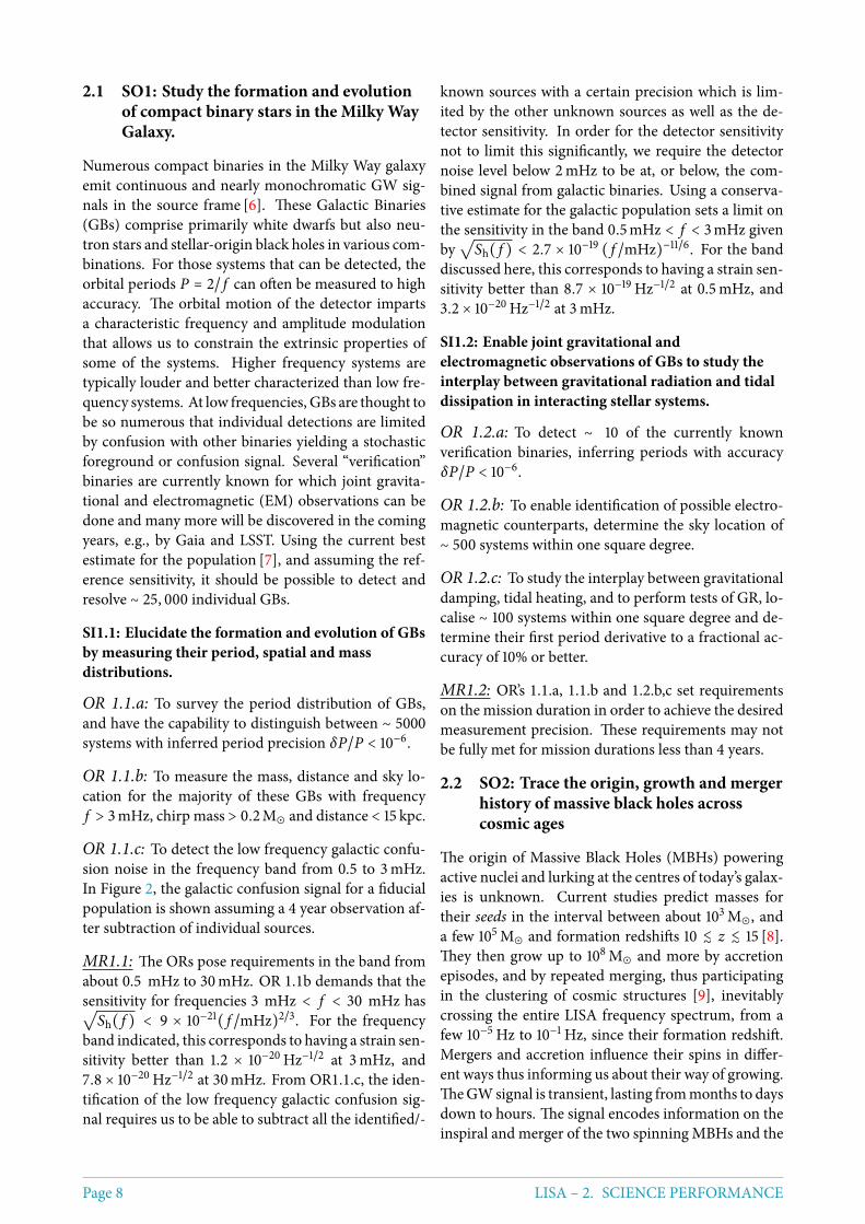
Figure 3: Massive black hole binary coalescences:contours of constant SNR for the baseline obser-vatory in the plane of total source-frame mass, M,and redshift, z (left margin-assuming Planck cos-mology), and luminosity distance, Dl (right mar-gin), for binaries with constant mass ratio of q =0.2. Overlaid are the positions of the threshold bi-naries used to define the mission requirements.
Figure 3 presents the richness of sources that shouldbe visible to LISA, showing a wide range of masses ob-servable with high SNR out to high redshift. The def-inition of the threshold systems (which are shown asred stars in Figure 3) for each OR leads to one or moreMR, shown in Figure 2.
SI2.1: Search for seed black holes at cosmic dawn
OR2.1 Have the capability to detect the inspiral ofMBHBs in the interval between a few 103M⊙ and a few105M⊙ in the source frame, and formation redshifts be-tween 10 and 15. Enable themeasurement of the sourceframe masses and the luminosity distance with a frac-tional error of 20% to distinguish formation models.
MR2.1: Ensure the strain sensitivity is better than 1.6×10⁻²⁰Hz−1/2 at 3.5mHz and 1 × 10⁻²⁰Hz−1/2 at 9mHz,to enable the observation of binaries at the low end ofthis parameter space with a SNR of at least 10. Sucha “threshold” system would have a mass of 3000M⊙,
mass ratio q = 0.2, and be located at a redshift of 15.All other MBHBs in OR2.1 with masses in the quotedrange and mass ratios higher than this and/or at lowerredshift, will then be detectedwith higher SNR yieldingbetter parameter estimation.
SI2.2: Study the growth mechanism of MBHs fromthe epoch of the earliest quasars
OR2.2.a Have the capability to detect the signal for co-alescing MBHs with mass 104 < M < 106M⊙ in thesource frame at z ≲ 9. Enable the measurement of thesource frame masses at the level limited by weak lens-ing (5 %).
OR2.2.b For sources at z < 3 and 105 < M < 106M⊙,enable the measurement of the dimensionless spin ofthe largest MBH with an absolute error better than 0.1and the detection of the misalignment of spins withthe orbital angular momentum better than 10 degrees.This parameter accuracy corresponds to an accumu-lated SNR (up to the merger) of at least ∼ 200.
MR2.2: The most stringent requirement is set by be-ing able to measure the spin of a threshold system withtotal intrinsic mass of 105M⊙, mass ratio of q = 0.2, lo-cated at z = 3. This will satisfy both OR2.1.a and 2.1.b.Achieving an SNR of 200 requires a strain sensitivityof 4 × 10⁻²⁰Hz−1/2 at 2mHz and 1.3 × 10⁻²⁰Hz−1/2 at20mHz. All systems in OR2.2.a and 2.2.b with highermass, mass ratios, spins, or lower redshift will result inhigher SNR, and better spin estimation.
SI2.3: Observation of EM counterparts to unveil theastrophysical environment aroundmerging binaries
OR2.3.a Observe themergers ofMilky-Way typeMB-HBs with total masses between 106 and 107M⊙ aroundthe peak of star formation (z ∼ 2), with sufficient SNRto allow the issuing of alerts to EM observatories witha sky-localisation of 100deg2 at least one day prior tomerger. This would yield coincident EM/GW observa-tions of the systems involved.
OR2.3.b After gravitationally observing the merger ofsystems discussed in OR2.3.a, the sky localisation willbe significantly improved, allowing follow-up EM ob-servations to take place. This has the potential to wit-ness the formation of a quasar following a BH merger.This needs excellent sky localisation (about 1 deg2) todistinguish from other variable EM sources in the fieldmonths to years after the merger.
MR2.3: For the lowest SNR system in OR2.3.a, whichcorresponds to a mass of 106M⊙ at z = 2, we will detectthe inspiral signal (with SNR=10) ∼ 11.5 days prior to
LISA – 2. SCIENCE PERFORMANCE Page 9
merger. Localising this source to 100deg2 requires anaccumulated SNR of ∼ 50, which will be known about32 hours prior to merger if the strain sensitivity of theobservatory is better than 7.2× 10⁻¹⁷Hz−1/2 at 0.1mHzand 1.9 × 10⁻¹⁸Hz−1/2 at 0.37mHz. To achieve this op-erationally, data from the observatory need to be madeavailable for analysis, around 1 day after measurementon-board. Additionally, in order to ensure coincidentobservations of GW and EM, we need to trigger a ‘pro-tected period’ on-board during which no commission-ing activities should take place. Hence there are threeMRs here: a constraint on the strain sensitivity; a con-straint on the cadence with which data are downloadedfrom the satellites; and the ability to trigger ‘protectedperiods’ where the instrument configuration is main-tained. For all other systems inOR2.3.a with lower red-shift, the SNR will be higher, and the sky-localisationcorrespondingly better.
SI2.4 Test the existence of Intermediate Mass BlackHole Binaries (IMBHBs)
OR2.4.a: Have the ability to detect the inspiral fromnearly equal mass IMBHBs of total intrinsic mass be-tween 600 and 104M⊙ at z < 1, measuring the com-ponent masses to a precision of 30%, which requires atotal accumulated SNR of at least 20.
MR2.4.a: Achieving a total SNR of about 20 for thesystems described in OR2.4.a requires the strain sen-sitivity of the observatory to be better than 4.2 ×10⁻²⁰Hz−1/2 at 2mHz and 1× 10⁻²⁰Hz−1/2 at 8mHz forthe threshold system of 600M⊙ with a mass ratio ofq = 1, located at z = 1.
OR2.4.b: Have the ability to detect unequal mass MB-HBs of total intrinsic mass 104 − 106M⊙ at z < 3 withthe lightest black hole (the IMBH) in the intermediatemass range (between 102 and 104M⊙) [11], measuringthe component masses to a precision of 10%, which re-quires a total accumulated SNR of at least 20.
MR2.4.b: Systems of OR2.4.b set constraints on thestrain sensitivity of the observatory along the descend-ing branch of the U-shaped curve where the galacticconfusion noise-like signal dominates. Achieving a to-tal SNRof 20 across that band for the systems describedin OR2.4.b requires the strain sensitivity of the obser-vatory to be better than 3×10⁻¹⁸Hz−1/2 at 0.3mHz, and2 × 10−20Hz−1/2 at 3mHz. This requirement holds aslong as the galactic confusion noise-like signal is at thelevel shown in Figure 2.
2.3 SO3: Probe the dynamics of dense nuclearclusters using EMRIs
Extreme Mass Ratio Inspirals (EMRIs) describe thelong-lasting inspiral (from months to a few years) andplunge of Stellar Origin Black Holes (SOBHs), withmass range 10 − 60 M⊙, into MBHs of 105 − 106 M⊙in the centre of galaxies [12]. The orbits of EMRIsare generic and highly relativistic. The SOBH spends103 − 105 orbits in close vicinity of the MBH, and theorbit displays extreme forms of periastron and orbitalplane precession. The large number of orbital cycles al-lows ultra precise measurements of the parameters ofthe binary system as the GW signal encodes informa-tion about the spacetime of the central massive object.Considering the large uncertainty in the astrophysicsof EMRIs, fulfillment of the requirements of this sec-tion would yield a minimum rate of one observed sys-tem per year, according to current most conservativeEMRI population models.
SI3.1 Study the immediate environment of MilkyWay like MBHs at low redshift
OR3.1: Have the ability to detect EMRIs aroundMBHs with masses of a few times 105M⊙ out to red-shift z = 4 (for maximally spinning MBHs, and EMRIson prograde orbits) with the SNR ≥ 20. This enablesan estimate of the redshifted, observer frame masseswith the accuracy δM/M < 10−4 for the MBH andδm/m < 10−3 for the SOBH. Estimate the spin of theMBH with an accuracy of 1 part in 103, the eccentricityand inclination of the orbit to one part in 103.
MR3.1: A threshold system for the range in OR3.1would have a central non-spinningMBHwith amass of5× 105M⊙, a SOBH of 10M⊙ on a circular orbit, at red-shift of 1.2. Such a system would have an accumulatedSNR of 20 over a 4 year mission if the strain sensitiv-ity of the observatory is better than 3.5 × 10⁻²⁰Hz−1/2at 3mHz and 2.3 × 10⁻²⁰Hz−1/2 at 7mHz. All othersystems with either lower redshift, higher componentmass, or higher spin will produce a higher SNR. Sys-tems with high spin and higher component mass maybe detected out to redshift 4. Additionally we requirethe absence of any strong (SNR > 5) spectral lines of in-strumental or environmental origin in the band from2 to 20mHz, which could interfere with the harmonicsof the GW signal from these systems. The plunge timewill be known to high accuracy several months ahead.It may also be useful to have the capability of triggeringa protected period of about 1 week around the plungetime to allow testing the accumulation of SNR againstGR.
Page 10 LISA – 2. SCIENCE PERFORMANCE
2.4 SO4: Understand the astrophysics ofstellar origin black holes
Following the LIGO discovery of SOBHs in the massrange from 10 to 30 M⊙ merging in binary systemsin the nearby Universe, a new science objective arisesfor LISA, which was not originally part of The Grav-itational Universe. Based on the inferred rates fromthe LIGO detections, fulfillment of the requirementsof this section would allow LISA to individually re-solve aminimumnumber of about 100 SOBH binaries,some of which would cross into the LIGO band weeksto months later, enabling multi-band GW astronomy[13].
SI4.1 Study the close environment of SOBHs byenabling multi-band and multi-messengerobservations at the time of coalescence
OR4.1: Have the ability to detect the inspiral signalfrom GW150914-like events with SNR > 7 after 4 yearsof observation and estimate the sky localisation with< 1deg2 and the time of coalescence in ground-baseddetectors to within oneminute. This will allow the trig-gering of alerts to ground-based detectors and to pre-point EM probes at the SOBH coalescence.
MR4.1: Detecting the inspiral of SOBHs with a masscomparable to those in the GW150914 system withSNR higher than 7, accumulated over 4 years, con-strains the rising branch of the sensitivity curve byrequiring a strain sensitivity of better than 1.2 ×10⁻²⁰Hz−1/2 at 14mHz rising to 4 × 10⁻²⁰Hz−1/2 at100mHz.
SI4.2 Disentangle SOBH binary formation channels
OR4.2: Have the ability to observe SOBH binarieswith total mass in excess of 50M⊙ out to redshift 0.1,with an SNR higher than 7 and a typical fractional er-ror on the mass of 1 part in 100 and eccentricity withan absolute error of 1 part in 103.
MR4.2: OR4.2 requires a strain sensitivity better than1.3 × 10−20Hz−1/2 between 5 and 20mHz.
2.5 SO5: Explore the fundamental nature ofgravity and black holes
MBHBs and EMRIs enable us to perform tests of GR inthe strong field regime and dynamical sector [14, 15].Precision tests such as these require ‘Golden’ binaries,that is, MBHBs with very high (> 100) SNR in the post-merger phase or EMRIS with SNR > 50.
SI5.1 Use ring-down characteristics observed inMBHB coalescences to test whether the post-mergerobjects are the black holes predicted by GR.
OR5.1 Have the ability to detect the post-merger partof the GW signal from MBHBs with M > 105M⊙ outto high redshift, and observemore than one ring-downmode to test the “no-hair” theorem of GR.
MR5.1: The range of systems defined in OR5.1 sets aconstraint on the sensitivity curve by requiring the highSNR and the observation of the merger. For masses atthe low endof the range, the threshold system is one outat z = 15with a mass of 105M⊙, which will give an SNRof ∼ 100 in the ringdown if the strain sensitivity is bet-ter than 2 × 10⁻²⁰Hz−1/2 at 3mHz and 1 × 10⁻²⁰Hz−1/2at 9mHz. The contours of SNR in the mass/redshiftplane are complicated, but we can constrain a point onthe high mass end by considering a system of 107M⊙out at redshift 4. This system constrains the strain sen-sitivity to be better than 7 × 10⁻¹⁷Hz−1/2 at 0.1mHz,and 3× 10⁻¹⁸Hz−1/2 at 0.3mHz, with the goal to extendthis sensitivity down to low frequencies to see more ofthe inspiral phase, and allow earlier detection. Systemswith masses between these two end points are consid-ered ‘Golden’ binaries, yielding SNRs of up to 1000 forsystems out to redshift 3.
SI5.2 Use EMRIs to explore the multipolar structureof MBHs
OR5.2: Have the ability to detect ‘Golden’ EMRIs(those are systems from OR3.1 with SNR > 50, spin> 0.9, and in a prograde orbit) and estimate themass ofthe SOBH with an accuracy higher than 1 part in 104,the mass of the central MBH with an accuracy of 1 partin 105, the spin with an absolute error of 10−4, and thedeviation from the Kerr quadrupole moment with anabsolute error of better than 10−3.
MR5.2: The MRs are the same as MR3.1, but due touncertainties in the astrophysical populations, a mis-sion lifetime of several years is essential here to increasethe chance of observing a Golden EMRI.
SI5.3 Testing for the presence of beyond-GRemission channels
Test the presence of beyond-GR emission channels(dipole radiation) to unprecedented accuracy by de-tecting GW150914-like binaries, which appear in boththe LISA andLIGO frequency bands [16]. TheORs andMRs are the same as those in SI4.1.
LISA – 2. SCIENCE PERFORMANCE Page 11
SI5.4 Test the propagation properties of GWs
Test propagation properties of GW signals from EM-RIs and from coalescing MBHBs. Detect the coales-cence of Golden MBHBs (those systems described inOR2.2 with an SNR > 200) and have the ability to de-tect a Golden EMRI (as defined inOR5.2) which allowsus to constrain the dispersion relation and set upperlimits on the mass of the graviton and possible Lorentzinvariance violations. The ORs and MRs are the sameas those in MR2.2 and MR3.1.
SI5.5 Test the presence of massive fields aroundmassive black holes with masses > 103M⊙
Constrain the masses of axion-like particles or othermassive fields arising in Dark-Matter models by accu-rately measuring the masses and spins of MBHs [17].The requirements on the accuracy of the mass and spinmeasurements are the same as in SI2.2.Investigate possible deviations in the dynamics (en-coded in the GW signal) of a solar mass objectspiralling into an intermediate mass BH (mass <a f ew104M⊙) due to the presence of a Dark Mattermini-spike around the IMBH [18]. This is a discoveryproject and the high frequency requirements stated inMR4.1, MR4.2 make such a discovery possible.
2.6 SO6: Probe the rate of expansion of theUniverse
LISA will probe the expansion of the Universe usingGW sirens at high redshifts: SOBH binaries (z < 0.2),EMRIs (z < 1.5), MBHBs (z < 6).
SI6.1: Measure the dimensionless Hubbleparameter by means of GW observations only
OR6.1a Have the ability to observe SOBH binarieswith total mass M > 50M⊙ at z < 0.1 with SNR higherthan 7 and typical sky location of < 1deg2.
OR6.1b Have the ability to localize EMRIs with anMBH mass of 5 × 10⁵M⊙ and an SOBH of 10M⊙ atz = 1.5 to better than 1deg2.
MR6.1: In terms of sensitivity curve, the OR6.1a-b areautomatically met if MR3.1 and MR4.1 are fulfilled.The need to collect a large enough sample of sourcestranslates into a minimal mission duration require-ment. According to current best population estimates,a 4 yearmission is needed to yield ameasurement of theHubble parameter to better than 0.02, which helps re-solving the tension among the values of the Hubble pa-rameter determined with local Universe standard can-dles and with the Cosmic Microwave Background.
SI6.2: Constrain cosmological parameters throughjoint GW and EM observations
OR6.2 Have the capability to observe mergers of MB-HBs in the mass range from 105 to 106M⊙ at z < 5,with accurate parameter estimation and sky error of< 10deg2 to trigger EM follow ups [19].
MR6.2 In terms of the sensitivity curve, OR6.2 is au-tomatically met if the MRs related to SO2 are fulfilled.The need to collect a large enough sample of sourcestranslates into a minimal mission duration require-ment. According to current best population estimates,a 4 yearmission is needed to yield ameasurement of theHubble parameter to 0.01 and the dark energy equationof state parameter,w0, to 0.1. Amission extension to 10years would yield an improvement of a factor of about2 on the measurement errors of these parameters.
2.7 SO7: Understand stochastic GWbackgrounds and their implications forthe early Universe and TeV-scale particlephysics
One of the LISA goals is the direct detection of astochasticGWbackground of cosmological origin (likefor example the one produced by a first-order phasetransition around the TeV scale) and stochastic fore-grounds. Probing a stochastic GW background of cos-mological origin provides information on new physicsin the early Universe. The shape of the signal givesan indication of its origin, while an upper limit allowsto constrain models of the early Universe and particlephysics beyond the standard model.For these investigations we need to ensure the avail-ability of the data streams needed to form the Sagnac(or null-stream) TDI channel where the GW signal ispartially suppressed in order to help separate the GWbackground from instrument noise.
SI7.1: Characterise the astrophysical stochastic GWbackground
OR7.1: Characterise the stochastic GW backgroundfrom SOBH binaries with energy density normalisedto the critical energy density in the Universe today, Ω,based on the inferred rates from the LIGO detections,i.e., at the lowest Ω = 2 × 10⁻¹⁰ ( f /25Hz)2/3 [20]. Thisrequires the ability to verify the spectral shape of thisstochastic background, and to measure its amplitudein the frequency ranges 0.8mHz < f < 4mHz and4mHz < f < 20mHz.
MR7.1: The SNR over the 4 years of observation mustbe larger than 10 in the two frequency ranges. It would
Page 12 LISA – 2. SCIENCE PERFORMANCE
correspond to a strain sensitivity of better than 4 ×10⁻²⁰( f /2.4mHz)−2Hz−1/2 for 0.8mHz < f < 4mHz(MR7.1a), and better than 1.6 × 10⁻²⁰Hz−1/2 for4mHz < f < 20mHz (MR7.1b).
SI7.2 : Measure, or set upper limits on, the spectralshape of the cosmological stochastic GWbackground
OR7.2: Probe a broken power-law stochastic back-ground from the early Universe as predicted, for ex-ample, by first order phase transitions [21] (other spec-tral shapes are expected, for example, for cosmic strings[22] and inflation [23]). Therefore, we need the abilityto measure Ω = 1.3 × 10⁻¹¹ ( f /10−4Hz)−1 in the fre-quency ranges 0.1mHz < f < 2mHz and 2mHz < f <20mHz, and Ω = 4.5 × 10⁻¹² ( f /10−2Hz)3 in the fre-quency ranges 2mHz < f < 20mHz and 0.02 < f <0.2Hz.
MR7.2: Ensure an SNR higher than 10 over the 4 yearsof observation in the three frequency ranges specifiedin OR7.2 .This would correspond to a strain sensitivity of bet-ter than 2.1 × 10⁻¹⁹( f /1mHz)−2.5Hz−1/2 (MR7.2a),1.6 × 10−20( f /11mHz)−0.5Hz−1/2 (MR7.2b), and9.3 × 10−20( f /0.11Hz)Hz−1/2 (MR7.2c) in the ranges0.1mHz < f < 2mHz, 2mHz < f < 20mHz and0.02Hz < f < 0.2Hz, respectively.
Additional remarks Probing the gaussianity, the po-larisation state, and/or the level of anisotropy of a po-tential stochastic background will give very impor-tant information about the origin of the background.In particular, limiting the number of instrumentalglitches will help to assess the gaussianity. The polari-sation state will be assessed with the 3 arm configura-tion. The measurement of the level of anisotropy de-pends on the frequency range and the amplitude of thebackground.
2.8 SO8: Search for GW bursts andunforeseen sources
LISA will lead us into uncharted territory, with the po-tential for many new discoveries. Distinguishing un-foreseen, unmodelled signals frompossible instrumen-tal artifacts will be one of the main challenges of themission, and will be crucial in exploring new astro-physical systems or unexpected cosmological sources.
SI8.1: Search for cusps and kinks of cosmic strings
Searching for GW bursts from cusps and kinks of cos-mic strings requires a deep understanding of the in-
strument noise and non-stationary behavior. Using theknown shape of the bursts in the time and frequencydomains will help to distinguish them from the instru-mental artifacts and fluctuations in the stationarity ofthe instrument noise floor. Having the ability to use theSagnac (or null-stream) TDI channels (MR7.2) to vetosuch instrumental events will play a crucial role in theexploration of this discovery space.
SI8.2: Search for unmodelled sources
Searching for GW bursts from completely unmodelledand unforeseen sources will also require a deep under-standing of the instrument noise and non-stationarybehavior. To distinguish such signals from instrumen-tal effects, it is essential that sources of instrumentalnon-stationary artifacts be kept as few as possible andthat we maintain the ability to form the Sagnac com-bination (which is insensitive to GWs at low frequen-cies). This requires that we maintain 6 laser links forthe full duration of the mission (MR7.2) and that wemake available the necessary data streams to allow re-quired computations on ground. This will help to vetoout all non-GW burst-like disturbances.
2.9 Summary
LISA is a mission of discovery. Revealing The Gravita-tional Universe in LISA’s frequency band will undoubt-edly greatly enhance our knowledge of the Universe.Apart from the observation of the known “verificationbinaries”, a lot of the science presented here depends onvarious models of astrophysical populations. Indeed,one of the primary goals of LISA is to constrain thosepopulation models. The baseline sensitivity proposedis one which is considered both technically feasible andat a level sufficient to achieve the science of The Gravi-tational Universe, given the current state of astrophysi-cal population models.The science addressed by LISA is extremely rich andcovers many different domains of astrophysics. Thereis therefore not a single criterion for success of the mis-sion, but success criteria for these various aspects ofLISA Science. They are summarized in Table 1. TheMission Requirements (MRs) laid out above, whichcollectively specify a robust strain sensitivity level atfrequencies between 0.1mHz and 100mHz over a sci-ence lifetime of at least 4 years with additional provi-sions for data latency and protected observing periods,define the sensitivity envelope required for completemission success on all Science Investigations (SIs). Ifany of these MRs are not met, there is a graceful degra-dation of the science performance, that will affect dif-ferently the various SIs. Alternatively, if any of these
LISA – 2. SCIENCE PERFORMANCE Page 13
MRs are exceeded, the mission may be able to outper-form some of its Observational Requirements (Ors).As Figure 1 shows, many of the LISA sources have ex-tremely high signal-to-noise ratio (SNR) and are hardlyaffected by slight changes of the sensitivity curve. Onthe other hand, the threshold systems for the Obser-vational Requirements (ORs) defining the envelope ofthe required sensitivity curve obviously are very sensi-tive to variations of the sensitivity curve.The various signals used in the SIs to answer the differ-ent science questions are affected by different regionsof the sensitivity curve. Also, some signals are affectedmore than others by the mission lifetime.For example, the detectability of the SOBHs of SO4 isstrongly affected by the high-frequency ( f ≳ 10mHz)performance of the observatory: assuming the currentestimate for the abundance of these sources, the base-line configuration should allow us to see on the orderof 100 of these systems over the nominal 4 year mis-sion. Improvements in high-frequency sensitivity ofa factor of 2 would yield about a factor of 3 more de-tectable sources, whereas loss in sensitivity in this bandby a factor of 2 will result in very few detections. Sim-ilarly, increasing the mission duration allows us to ob-serve these systems for longer times, accumulate SNR,and enables us to detect more systems.Another example, at the low-frequency end of themeasurement band, arises from the ability to triggerelectro-magnetic follow-up observations. MR2.3 spellsthis out for the baseline configuration, but the resultsare strongly dependent on the low-frequency perfor-mance. An improvement of the low-frequency perfor-mance by a factor of 4 pushes out the possible alert timefrom 1.5 weeks to 4 weeks, whereas a loss of low fre-quency performance by a factor of 4 will reduce the ad-vance alert time to 2 days.
Looking at themost sensitive band of the observatory, anumber of sources are affected by the level of sensitivitythere. For example, the ability to make high precisionmeasurements of parameters of MBHBs, such as thespin, requires very high SNRs of around 200. The num-ber of systems we will be able to see with such SNRswill depend very strongly on the ‘reach’ of the obser-vatory. Given the baseline, systems such as those inSI2.2 will be observable out to redshift 20 with suffi-cient SNR. Reducing the sensitivity of the observatoryin the ∼ 10mHz frequency range reduces the observa-tory reach, and hence the number of potentially ob-servable systems.During the Phase 0 and Phase A studies, the trade-offbetween these non-independent requirements needsto be carefully examined to achieve the optimum sci-ence performance within a constrained budget. Tosupport this trade-off, the consortium is preparing ascience metric document that quantitatively identifieshow some of the science is affected by graceful degra-dation or improved performance.
The Gravitational UniverseObjectives
Mission SuccessCriteria
Trace the formation, growth, andmerger history of massive blackholes
Perform SIs for SO2
Explore stellar populations anddynamics in galactic nuclei
Perform SIs for SO3
Test GR with observations Perform SIs for SO5Probe new physics and cosmology Perform SIs for SO6,
SO7 and SO8Survey compact stellar-massbinaries and study the structure ofthe Galaxy
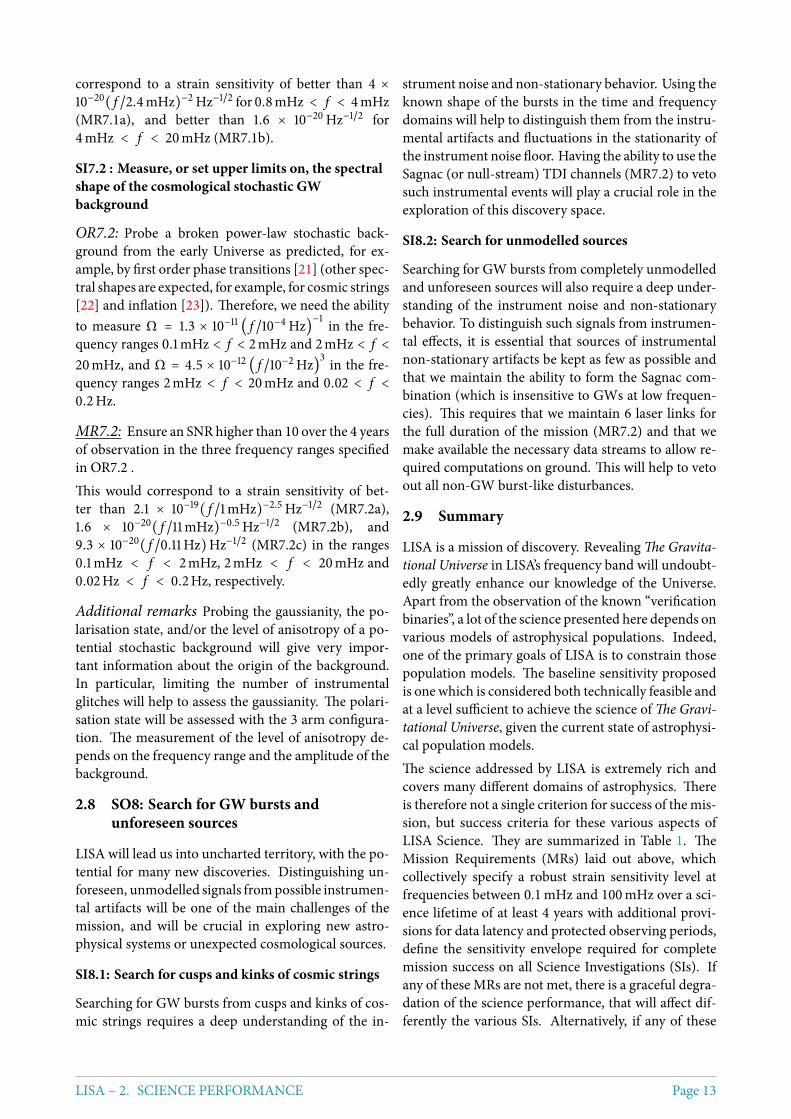
Perform SIs for SO1and SO4
Table 1: Association of mission success criteriawith the science objectives as summarized in theThe Gravitational Universe theme document.
3 Mission Profile
GWs change the light travel time or the optical path-length between free falling [24] test masses (TMs).These test masses and the surrounding GravitationalReference Sensor (GRS) hardware will exploit the fullflight heritage of the same systems used on LISAPathfinder. The test masses will follow their geodesictrajectories with sub-femto g/
√Hz spurious accelera-
tion. They will be located inside three identical S/Cin a triangular formation separated by 2.5 million km.Laser interferometers (IFOs) will measure the pm to
nm pathlength variations caused by GWs. The inter-ferometers are all-sky monitors of GWs and do notrequire nor allow for any pointing towards specificsources. The constellation will follow its initial orbitwith very little to no orbital corrections and can ob-serve continuously.
3.1 Orbit
The proposed orbit for LISA is an Earth-trailing helio-centric orbit between 50 and 65million km fromEarth,
Page 14 LISA – 3. MISSION PROFILE
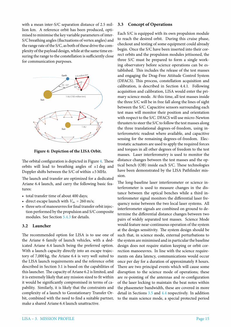
with a mean inter-S/C separation distance of 2.5 mil-lion km. A reference orbit has been produced, opti-mised tominimise the key variable parameters of inter-S/C breathing angles (fluctuations of vertex angles) andthe range rate of the S/C, as both of these drive the com-plexity of the payload design, while at the same time en-suring the range to the constellation is sufficiently closefor communication purposes.
Earth
Sun1 AU (150 million km)
19 – 23°60°
2.5 million km
1 AUSun
Figure 4: Depiction of the LISA Orbit.
The orbital configuration is depicted in Figure 4. Theseorbits will lead to breathing angles of ±1 deg andDoppler shifts between the S/C of within ±5MHz.The launch and transfer are optimized for a dedicatedAriane 6.4 launch, and carry the following basic fea-tures:• total transfer time of about 400 days;• direct escape launch with V∞ = 260m/s;• three sets ofmanoeuvres for final transfer orbit injec-
tion performed by the propulsion and S/C compositemodules. See Section 5.4.3 for details.
3.2 Launcher
The recommended option for LISA is to use one ofthe Ariane 6 family of launch vehicles, with a ded-icated Ariane 6.4 launch being the preferred option.With a launch capacity directly into an escape trajec-tory of 7,000 kg, the Ariane 6.4 is very well suited tothe LISA launch requirements and the reference orbitdescribed in Section 3.1 is based on the capabilities ofthis launcher. The capacity of Ariane 6.2 is limited, andit is extremely likely that any mission sized to fit withinit would be significantly compromised in terms of ca-pability. Similarly, it is likely that the constraints andcomplexity of a launch to Geostationary Transfer Or-bit, combined with the need to find a suitable partner,make a shared Ariane 6.4 launch unattractive.
3.3 Concept of Operations
Each S/C is equipped with its own propulsion moduleto reach the desired orbit. During this cruise phase,checkout and testing of some equipment could alreadybegin. Once the S/C have been inserted into their cor-rect orbits and the propulsion modules jettisoned, thethree S/C must be prepared to form a single work-ing observatory before science operations can be es-tablished. This includes the release of the test massesand engaging the Drag-Free Attitude Control System(DFACS). This process, constellation acquisition andcalibration, is described in Section 4.4.1. Followingacquisition and calibration, LISA would enter the pri-mary science mode. At this time, all test masses insidethe three S/C will be in free fall along the lines of sightbetween the S/C. Capacitive sensors surrounding eachtest mass will monitor their position and orientationwith respect to the S/C. DFACS will use micro-Newtonthrusters to steer the S/C to follow the testmasses alongthe three translational degrees-of-freedom, using in-terferometric readout where available, and capacitivesensing for the remaining degrees-of-freedom. Elec-trostatic actuators are used to apply the required forcesand torques in all other degrees of freedom to the testmasses. Laser interferometry is used to monitor thedistance changes between the test masses and the op-tical bench (OB) inside each S/C. These technologieshave been demonstrated by the LISA Pathfinder mis-sion.The long-baseline laser interferometer or science in-terferometer is used to measure changes in the dis-tance between the optical benches while a third in-terferometer signal monitors the differential laser fre-quency noise between the two local laser systems. Allinterferometer signals are combined on ground to de-termine the differential distance changes between twopairs of widely separated test masses. Science Modewould feature near-continuous operation of the systemat the design sensitivity. The system design should besuch that, in science mode, external perturbations tothe system areminimised and in particular the baselinedesign does not require station keeping or orbit cor-rection manoeuvres. In line with the science require-ments on data latency, communications would occuronce per day for a duration of approximately 8 hours.There are two principal events which will cause somedisruption to the science mode of operations; theseare re-pointing of the antennas and re-configurationof the laser locking to maintain the beat notes withinthe phasemeter bandwidth, these are covered in moredetail in Sections 3.5 and 4.4 respectively. In additionto the main science mode, a special protected period
LISA – 3. MISSION PROFILE Page 15
mode is envisaged. As identified in Section 2, therewill be occasions when it is possible, with advance no-tice of around one week, to predict the time of a spe-cific merger event. In this case, the protected periodmode would be triggered to ensure that, over the ∼ 1day around the merger event there were no disrup-tions to the system. In particular, this would mean noantenna re-pointing and no laser frequency switching.This could be achieved by applying 1-2 days margin tothe planned switching intervals, such that a plannedre-pointing/switching could be moved out of the pro-tected period.
3.4 Mission Lifetime
We propose a nominal mission duration of 4 yearsin science mode. Within this time, the key sciencerequirements can be addressed to a suitable level asdiscussed in Section 2. Given the revolutionary andunique nature of LISA, however, the mission shouldbe designedwith consumables (e.g., DFACSpropellant,available power) and orbital stability to facilitate a totalmission up to 10 years in duration.
3.5 Communication requirements andstrategy
The entire constellation is expected to produce about35 kbit/s of data in the nominal science mode, as de-
scribed in Section 5, Table 7, leading to a daily totalof 334 MB. We augment the bidirectional laser linksbetween each S/C with data links (around 15 kbit/sbidirectionally) by modulating data on the pseudo-random code used for ranging. This has been demon-strated with representative power levels at AEI andJPL [25, 26, 27]. Ground communication could thentake place with only one of the three S/C per pass andstill serve the whole constellation. With this configura-tion, it has been calculated that for a single pointing ofone antenna, communications can be maintained witha single ground station for 3 days at a user data rate of> 108.5 kbps using X band, see Section 5.4.3. This al-lows the re-pointing of the antenna to happen once ev-ery 9 days (by cycling through the constellation), whilestill enabling daily communications with LISA to min-imise data latency. At a rate of ≥ 108.5 kbps, and with adaily communications schedule, the complete 334MBset of nominal data can be transmitted in < 7.2 hours.For a single station of the ESA ground network theminimum contact time per day to the LISA orbit hasbeen calculated to be around 8 hours - sufficient forthe nominal science data stream. Additionally, by util-ising multiple ground stations (New Norcia, Cebrerosand Malargue) the contact window could be extendedto > 23 hours a day. While not the baseline, this optioncould be useful for calibration and commissioning op-erations.
4 Model Payload
4.1 Description of the measurementtechnique
LISA will detect gravitational waves with an interfero-metric measurement of differential optical pathlengthmodulation along the three sides of a triangular con-figuration defined by free-falling test masses, which arecontained inside co-orbiting drag-free spacecraft. Thedistance changes between the test masses caused bythe GWs are small (pm to nm) compared to the varia-tions caused by solar system celestial dynamics (some10000 km), but can be distinguished because the for-mer are at mHz frequencies (1000 seconds timescale),whereas the latter have periods of many months andare quiet at mHz frequencies.The optical pathlength measurement uses continu-ously operating heterodyne laser interferometers inboth directions along each arm, using stable lasers at1064 nm and a few Watts of power transmitted at each
end. The beamdivergence over severalmillion km lim-its the received laser light power to some 100 pW,whichrules out passive reflection for the return path. Instead,each S/C acts as an active transponder, transmitting afresh high-power beam that is phase-locked to the in-coming weak beam, with a fixed offset frequency. Theconstellation is fully symmetric, with similar measure-ments taking place in both directions along each of thethree arms.Three independent interferometric combinations ofthe light travel time measurements between the testmasses are possible, allowing, in data processing onground, the synthesis of two virtual Michelson inter-ferometers plus a third (“Sagnac”) configuration thatis largely insensitive to GWs. The two independentMichelson interferometers allow simultaneous mea-surement of the two possible polarisations of the GW,and the Sagnac combination can be used to charac-terise the instrumental noise background. The yearly
Page 16 LISA – 4. MODEL PAYLOAD
rotation of the constellation about itself and its orbitaround the Sun allows to reconstruct the source direc-tion on the sky for sources that can be observed for atleast several weeks.Noisy non-gravitational forces acting on the spacecraftrequire the use of test masses as geodesic reference testparticles, which are shielded by the containing S/C.Two TM per spacecraft are used, each one dedicated toa single interferometry arm. To limit the relative S/C– TM accelerations, the spacecraft are “drag-free con-trolled” with micro-Newton thrusters to follow eachTM along its interferometry arm, with no forces ap-plied to the TM along these measurement axes. The to-tal TM-TM measurement along each arm is separatedinto three parts:• TM1 (test mass 1) to optical bench in S/C 1 (local);• optical bench in S/C 1 to optical bench in S/C 2
through telescopes (long arm); and• optical bench in S/C 2 to TM2 (local).As orbital dynamics gives rise to relative velocitiesof order ±5m/s between the S/C, the interferometricphasemeasurement systemwill have to track ∼ 5MHz-frequency Doppler shifts in the long, S/C to S/C inter-ferometry measurement. Combining these three mea-surements in post-processing on ground will yield thedesiredTM toTMseparation, and further postprocess-ing by the Time-Delay Interferometry [28] (TDI) algo-rithm will remove the otherwise dominating laser fre-quency noise by synthesizing virtual equal-armlengthinterferometers. The absolute inter-spacecraft dis-tances are determined to the required ∼ 10 cm accuracyusing an auxiliary modulation on the laser beams.
4.2 Key measurement performancerequirement
The strain sensitivity curve shown in Section 2 is deter-mined by three main parameters listed below. We pro-pose to set requirements above 0.1mHz to limit the ef-fort of testing but furthermore require that no featuresof the design shall preclude reaching the goal sensitiv-ity down to 20 µHz.
Stray accelerations of the geodesic reference TM.The proposed requirement is
S1/2a ≤ 3⋅10−15m s−2√Hz⋅
¿ÁÁÀ1 + (0.4mHz
f)2
⋅
¿ÁÁÀ1 + ( f
8mHz)4
100 µHz ≤ f ≤ 0.1Hz req.20 µHz ≤ f ≤ 1Hz goal
where S1/2a is the single TM acceleration noise level.
Note that the conversion from acceleration to displace-ment gives the 1/ f 2 slope in the sensitivity graph (seeFigure 2). This requirement mostly applies to the GRSthat comprises the TM and the surrounding sensingand actuation hardware. The quoted level correspondsto what has been demonstrated by the LISA Pathfinderdifferential acceleration performance, with a little mar-gin included. Further details and derived requirementsare described below.
Displacement noise of the interferometric TM--to-TM ranging with a proposed requirement of
S1/2IFO ≤ 10 ⋅ 10−12 m√
Hz⋅
¿ÁÁÀ1 + (2mHz
f)4
100 µHz ≤ f ≤ 0.1Hz req.20 µHz ≤ f ≤ 1Hz goal
where S1/2IFO is the effective total displacement noise ina one-way single link TM to TM measurement. Thismainly concerns the interferometric measurement sys-tem, comprising the telescope, optical bench, phasemeasurement system, laser, clock and TDI process-ing. The local (TM to OB) part of that measurementhas been demonstrated in LISA Pathfinder with am-ple performance margin, and the long arm measure-ment is addressed by technology development on theground (see Section 7). That development will alsobenefit from the experience gained in developing thefirst long-distance inter-spacecraft laser interferometeron GRACE Follow-On [29], to be launched in early2018.
Above approximately 30 mHz strain noise increaseswith frequency as the Gravitational Wave period be-comes shorter than the round trip light time, resultingin a partial cancellation of the signal.These noise levels are expected to be achievable withthe following strawman parameters, to be optimised inPhase A:• GRS from LPF with two TMs per S/C (46mm cubic,
2 kg Au-Pt TM);• armlength: 2.5million km;• telescopes with 30 cm diameter;• laser power: 2W end-of-life (EOL) out of the deliv-
ery fibre to the OB.The above parameters lead to a received power ofabout 700 pW at the entrance aperture of the telescope,which results in a shot noise contribution of about4.7 pm/
√Hz in S1/2IFO.
LISA – 4. MODEL PAYLOAD Page 17
4.3 Payload conceptual design and keycharacteristics
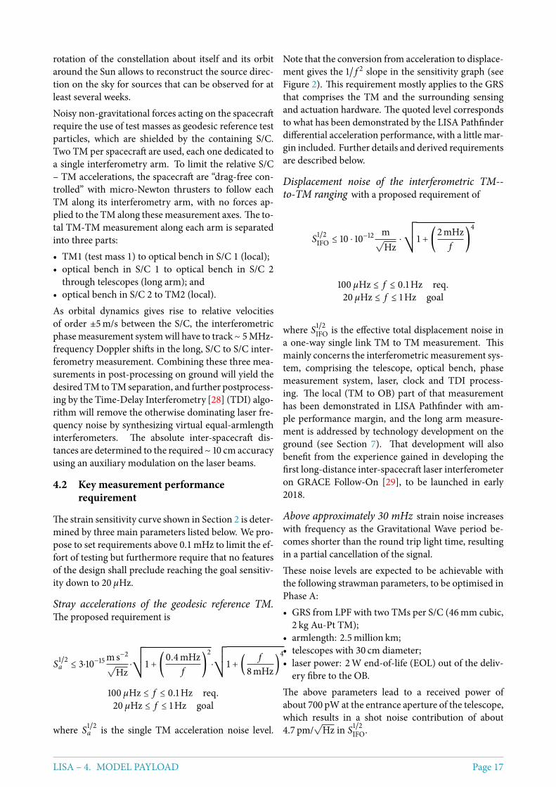
A strawman design of the payload on each of the threeidentical S/C is illustrated in the diagram in Figure 5.It consists of two identical assemblies of roughly cylin-drical shape, each of which contains a telescope, an op-tical bench and a GRS with enclosed TM, connectedby a mounting structure which allows sequential mu-tual alignment during integration. The two assembliesare mounted in a common frame that allows rotationof each assembly about the vertical axis by about 2 de-grees in order to track the variation of the vertex angles(60 ± 1) due to solar system dynamics.A possible alternative configuration, which should beviewed as a backup as it would involve departures fromthe proven LPF GRS design, has two telescopes rigidlyfixed to a single, common, optical bench and requiresan “in-field pointing” actuator in each optical path tocompensate the angular variation. A detailed trade-offbetween these options and a revised design of the pay-load are expected in Phase A.
Figure 5: Payload strawman conceptual de-sign. Images courtesy of Airbus D&S GmbH,Friedrichshafen.
4.4 Interferometry Measurement System(IMS)
The IMS is using optical benches which will be con-structed from an ultra-low expansion glass-ceramicmaterial tominimise optical pathlength changes due totemperature fluctuations. Each optical bench hosts one‘science’ interferometer for the received light from thefar spacecraft, one local interferometer whichmonitorsthe position and orientation of the test mass, and a ref-erence interferometer. The latter two interferometersuse a fraction of the two local laser beams to generatethe laser beat signals. The science interferometer canuse either of the two lasers together with the weak far
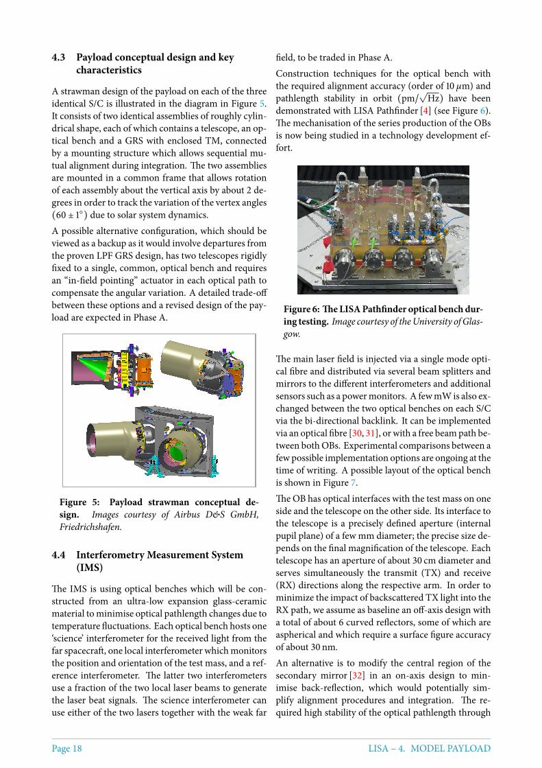
field, to be traded in Phase A.Construction techniques for the optical bench withthe required alignment accuracy (order of 10 µm) andpathlength stability in orbit (pm/
√Hz) have been
demonstrated with LISA Pathfinder [4] (see Figure 6).The mechanisation of the series production of the OBsis now being studied in a technology development ef-fort.
Figure 6: TheLISAPathfinder optical bench dur-ing testing. Image courtesy of theUniversity ofGlas-gow.
The main laser field is injected via a single mode opti-cal fibre and distributed via several beam splitters andmirrors to the different interferometers and additionalsensors such as a powermonitors. A fewmWis also ex-changed between the two optical benches on each S/Cvia the bi-directional backlink. It can be implementedvia an optical fibre [30, 31], or with a free beampath be-tween bothOBs. Experimental comparisons between afew possible implementation options are ongoing at thetime of writing. A possible layout of the optical benchis shown in Figure 7.The OB has optical interfaces with the test mass on oneside and the telescope on the other side. Its interface tothe telescope is a precisely defined aperture (internalpupil plane) of a few mm diameter; the precise size de-pends on the final magnification of the telescope. Eachtelescope has an aperture of about 30 cm diameter andserves simultaneously the transmit (TX) and receive(RX) directions along the respective arm. In order tominimize the impact of backscattered TX light into theRX path, we assume as baseline an off-axis design witha total of about 6 curved reflectors, some of which areaspherical and which require a surface figure accuracyof about 30 nm.An alternative is to modify the central region of thesecondary mirror [32] in an on-axis design to min-imise back-reflection, which would potentially sim-plify alignment procedures and integration. The re-quired high stability of the optical pathlength through
Page 18 LISA – 4. MODEL PAYLOAD
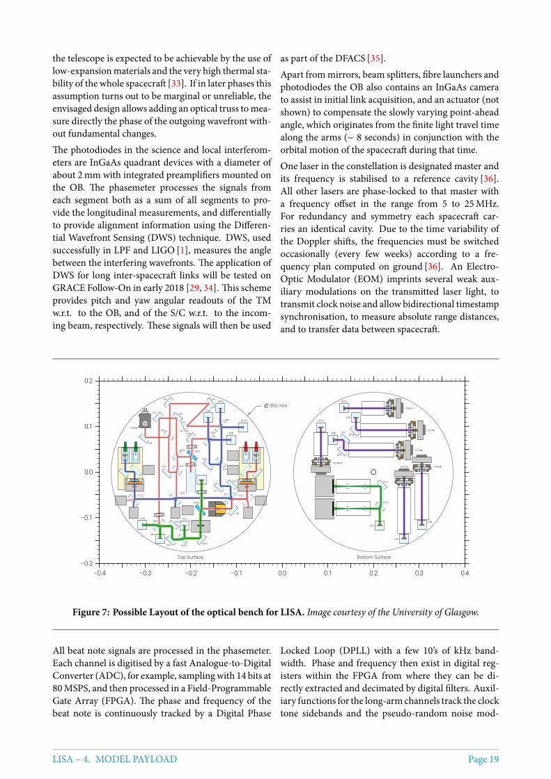
the telescope is expected to be achievable by the use oflow-expansionmaterials and the very high thermal sta-bility of the whole spacecraft [33]. If in later phases thisassumption turns out to be marginal or unreliable, theenvisaged design allows adding an optical truss tomea-sure directly the phase of the outgoing wavefront with-out fundamental changes.The photodiodes in the science and local interferom-eters are InGaAs quadrant devices with a diameter ofabout 2mm with integrated preamplifiers mounted onthe OB. The phasemeter processes the signals fromeach segment both as a sum of all segments to pro-vide the longitudinal measurements, and differentiallyto provide alignment information using the Differen-tial Wavefront Sensing (DWS) technique. DWS, usedsuccessfully in LPF and LIGO [1], measures the anglebetween the interfering wavefronts. The application ofDWS for long inter-spacecraft links will be tested onGRACE Follow-On in early 2018 [29, 34]. This schemeprovides pitch and yaw angular readouts of the TMw.r.t. to the OB, and of the S/C w.r.t. to the incom-ing beam, respectively. These signals will then be used
as part of the DFACS [35].Apart frommirrors, beam splitters, fibre launchers andphotodiodes the OB also contains an InGaAs camerato assist in initial link acquisition, and an actuator (notshown) to compensate the slowly varying point-aheadangle, which originates from the finite light travel timealong the arms (∼ 8 seconds) in conjunction with theorbital motion of the spacecraft during that time.One laser in the constellation is designated master andits frequency is stabilised to a reference cavity [36].All other lasers are phase-locked to that master witha frequency offset in the range from 5 to 25MHz.For redundancy and symmetry each spacecraft car-ries an identical cavity. Due to the time variability ofthe Doppler shifts, the frequencies must be switchedoccasionally (every few weeks) according to a fre-quency plan computed on ground [36]. An Electro-Optic Modulator (EOM) imprints several weak aux-iliary modulations on the transmitted laser light, totransmit clock noise and allow bidirectional timestampsynchronisation, to measure absolute range distances,and to transfer data between spacecraft.
−0.4 −0.3 −0.2 −0.1 0.0 0.1 0.2 0.3 0.4−0.2
−0.1
0.0
0.1
0.2
Top Surface Bottom Surface
350 mm
PCO1PCO2
BS3
BS4
BS6
BS9
BS10
BS1BS2
BS5
BS7
BS8
PBS1
PBS2
M1M2
M3
M4
M5 M6
M7M8
M9
M10
M11
M12
M13M14
M15
PDPWR
ACQ
SciA
SciB
TMA
TMB
REFA
REFB
ACQ
SciA
SciB
TMA
TMB
REFA
REFB
BS11
M16
M17
M18
M19
PDSCIBPDSCIA
PDTMA
PDTMB
PDREFA
PDREFB
Figure 7: Possible Layout of the optical bench for LISA. Image courtesy of the University of Glasgow.
All beat note signals are processed in the phasemeter.Each channel is digitised by a fast Analogue-to-DigitalConverter (ADC), for example, samplingwith 14 bits at80MSPS, and then processed in a Field-ProgrammableGate Array (FPGA). The phase and frequency of thebeat note is continuously tracked by a Digital Phase
Locked Loop (DPLL) with a few 10’s of kHz band-width. Phase and frequency then exist in digital reg-isters within the FPGA from where they can be di-rectly extracted and decimated by digital filters. Auxil-iary functions for the long-armchannels track the clocktone sidebands and the pseudo-random noise mod-
LISA – 4. MODEL PAYLOAD Page 19
ulation for use in the TDI algorithm on ground andthe inter-spacecraft data transfer. Full functionalityand required performance of the phasemeter have beendemonstrated both in Europe and the US [37, 38].
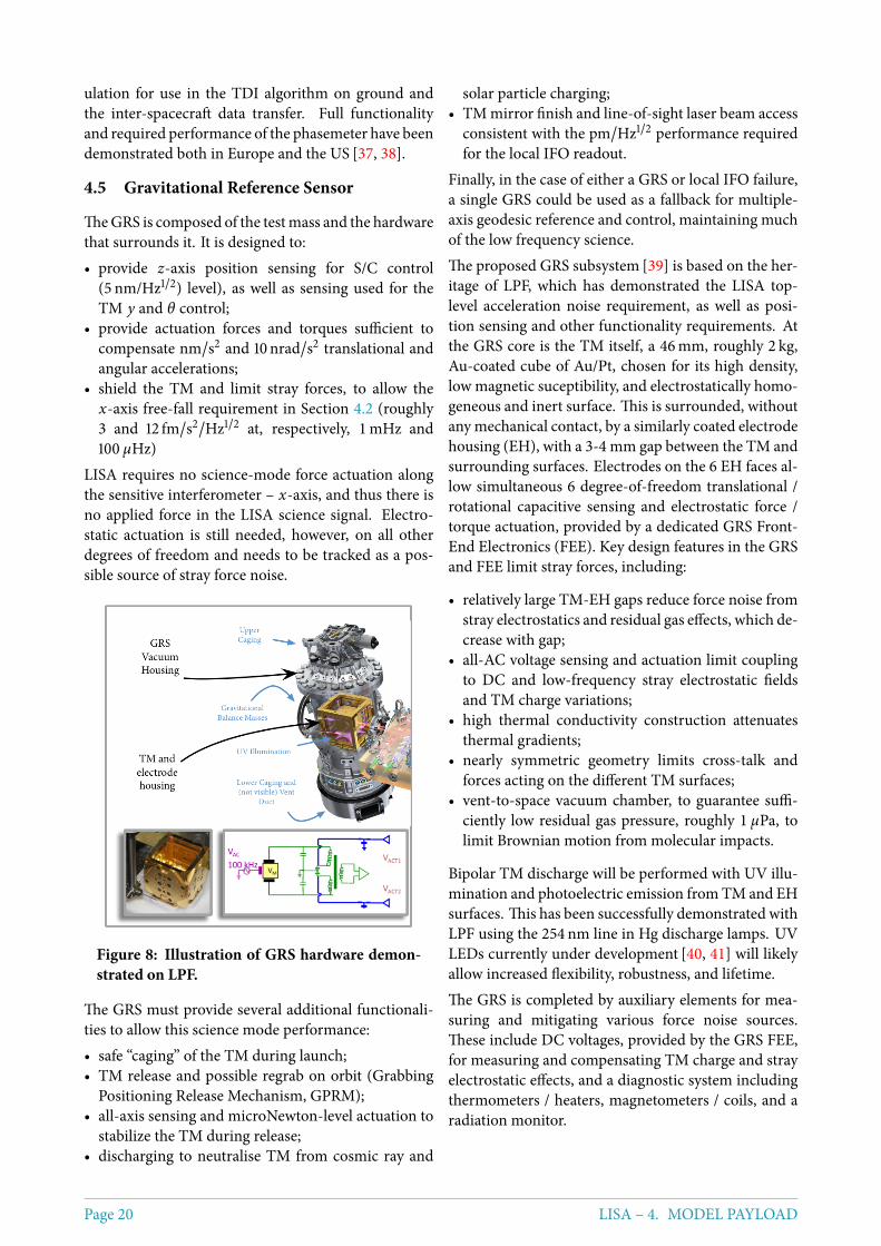
4.5 Gravitational Reference Sensor
TheGRS is composed of the testmass and the hardwarethat surrounds it. It is designed to:• provide z-axis position sensing for S/C control
(5 nm/Hz1/2) level), as well as sensing used for theTM y and θ control;
• provide actuation forces and torques sufficient tocompensate nm/s2 and 10nrad/s2 translational andangular accelerations;
• shield the TM and limit stray forces, to allow thex-axis free-fall requirement in Section 4.2 (roughly3 and 12 fm/s2/Hz1/2 at, respectively, 1mHz and100 µHz)
LISA requires no science-mode force actuation alongthe sensitive interferometer – x-axis, and thus there isno applied force in the LISA science signal. Electro-static actuation is still needed, however, on all otherdegrees of freedom and needs to be tracked as a pos-sible source of stray force noise.
Figure 8: Illustration of GRS hardware demon-strated on LPF.
The GRS must provide several additional functionali-ties to allow this science mode performance:• safe “caging” of the TM during launch;• TM release and possible regrab on orbit (Grabbing
Positioning Release Mechanism, GPRM);• all-axis sensing and microNewton-level actuation to
stabilize the TM during release;• discharging to neutralise TM from cosmic ray and
solar particle charging;• TM mirror finish and line-of-sight laser beam access
consistent with the pm/Hz1/2 performance requiredfor the local IFO readout.
Finally, in the case of either a GRS or local IFO failure,a single GRS could be used as a fallback for multiple-axis geodesic reference and control, maintaining muchof the low frequency science.The proposed GRS subsystem [39] is based on the her-itage of LPF, which has demonstrated the LISA top-level acceleration noise requirement, as well as posi-tion sensing and other functionality requirements. Atthe GRS core is the TM itself, a 46mm, roughly 2 kg,Au-coated cube of Au/Pt, chosen for its high density,low magnetic suceptibility, and electrostatically homo-geneous and inert surface. This is surrounded, withoutanymechanical contact, by a similarly coated electrodehousing (EH), with a 3-4 mm gap between the TM andsurrounding surfaces. Electrodes on the 6 EH faces al-low simultaneous 6 degree-of-freedom translational /rotational capacitive sensing and electrostatic force /torque actuation, provided by a dedicated GRS Front-End Electronics (FEE). Key design features in the GRSand FEE limit stray forces, including:
• relatively large TM-EH gaps reduce force noise fromstray electrostatics and residual gas effects, which de-crease with gap;
• all-AC voltage sensing and actuation limit couplingto DC and low-frequency stray electrostatic fieldsand TM charge variations;
• high thermal conductivity construction attenuatesthermal gradients;
• nearly symmetric geometry limits cross-talk andforces acting on the different TM surfaces;
• vent-to-space vacuum chamber, to guarantee suffi-ciently low residual gas pressure, roughly 1 µPa, tolimit Brownian motion from molecular impacts.
Bipolar TM discharge will be performed with UV illu-mination and photoelectric emission fromTM and EHsurfaces. This has been successfully demonstrated withLPF using the 254 nm line in Hg discharge lamps. UVLEDs currently under development [40, 41] will likelyallow increased flexibility, robustness, and lifetime.The GRS is completed by auxiliary elements for mea-suring and mitigating various force noise sources.These include DC voltages, provided by the GRS FEE,for measuring and compensating TM charge and strayelectrostatic effects, and a diagnostic system includingthermometers / heaters, magnetometers / coils, and aradiation monitor.
Page 20 LISA – 4. MODEL PAYLOAD
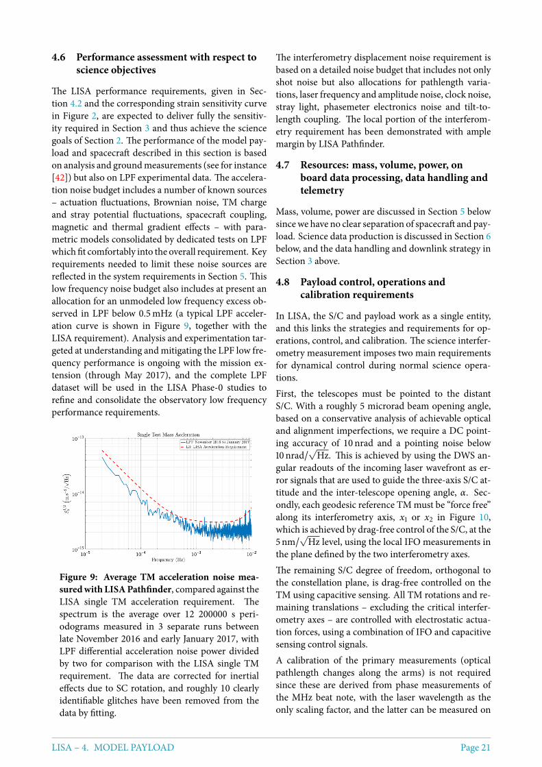
4.6 Performance assessment with respect toscience objectives
The LISA performance requirements, given in Sec-tion 4.2 and the corresponding strain sensitivity curvein Figure 2, are expected to deliver fully the sensitiv-ity required in Section 3 and thus achieve the sciencegoals of Section 2. The performance of the model pay-load and spacecraft described in this section is basedon analysis and groundmeasurements (see for instance[42]) but also on LPF experimental data. The accelera-tion noise budget includes a number of known sources– actuation fluctuations, Brownian noise, TM chargeand stray potential fluctuations, spacecraft coupling,magnetic and thermal gradient effects – with para-metric models consolidated by dedicated tests on LPFwhich fit comfortably into the overall requirement. Keyrequirements needed to limit these noise sources arereflected in the system requirements in Section 5. Thislow frequency noise budget also includes at present anallocation for an unmodeled low frequency excess ob-served in LPF below 0.5mHz (a typical LPF acceler-ation curve is shown in Figure 9, together with theLISA requirement). Analysis and experimentation tar-geted at understanding and mitigating the LPF low fre-quency performance is ongoing with the mission ex-tension (through May 2017), and the complete LPFdataset will be used in the LISA Phase-0 studies torefine and consolidate the observatory low frequencyperformance requirements.
Figure 9: Average TM acceleration noise mea-suredwith LISAPathfinder, compared against theLISA single TM acceleration requirement. Thespectrum is the average over 12 200000 s peri-odograms measured in 3 separate runs betweenlate November 2016 and early January 2017, withLPF differential acceleration noise power dividedby two for comparison with the LISA single TMrequirement. The data are corrected for inertialeffects due to SC rotation, and roughly 10 clearlyidentifiable glitches have been removed from thedata by fitting.
The interferometry displacement noise requirement isbased on a detailed noise budget that includes not onlyshot noise but also allocations for pathlength varia-tions, laser frequency and amplitude noise, clock noise,stray light, phasemeter electronics noise and tilt-to-length coupling. The local portion of the interferom-etry requirement has been demonstrated with amplemargin by LISA Pathfinder.
4.7 Resources: mass, volume, power, onboard data processing, data handling andtelemetry
Mass, volume, power are discussed in Section 5 belowsincewe have no clear separation of spacecraft and pay-load. Science data production is discussed in Section 6below, and the data handling and downlink strategy inSection 3 above.
4.8 Payload control, operations andcalibration requirements
In LISA, the S/C and payload work as a single entity,and this links the strategies and requirements for op-erations, control, and calibration. The science interfer-ometry measurement imposes two main requirementsfor dynamical control during normal science opera-tions.First, the telescopes must be pointed to the distantS/C. With a roughly 5 microrad beam opening angle,based on a conservative analysis of achievable opticaland alignment imperfections, we require a DC point-ing accuracy of 10 nrad and a pointing noise below10nrad/
√Hz. This is achieved by using the DWS an-
gular readouts of the incoming laser wavefront as er-ror signals that are used to guide the three-axis S/C at-titude and the inter-telescope opening angle, α. Sec-ondly, each geodesic reference TM must be “force free”along its interferometry axis, x1 or x2 in Figure 10,which is achieved by drag-free control of the S/C, at the5nm/
√Hz level, using the local IFO measurements in
the plane defined by the two interferometry axes.The remaining S/C degree of freedom, orthogonal tothe constellation plane, is drag-free controlled on theTM using capacitive sensing. All TM rotations and re-maining translations – excluding the critical interfer-ometry axes – are controlled with electrostatic actua-tion forces, using a combination of IFO and capacitivesensing control signals.A calibration of the primary measurements (opticalpathlength changes along the arms) is not requiredsince these are derived from phase measurements ofthe MHz beat note, with the laser wavelength as theonly scaling factor, and the latter can be measured on
LISA – 4. MODEL PAYLOAD Page 21
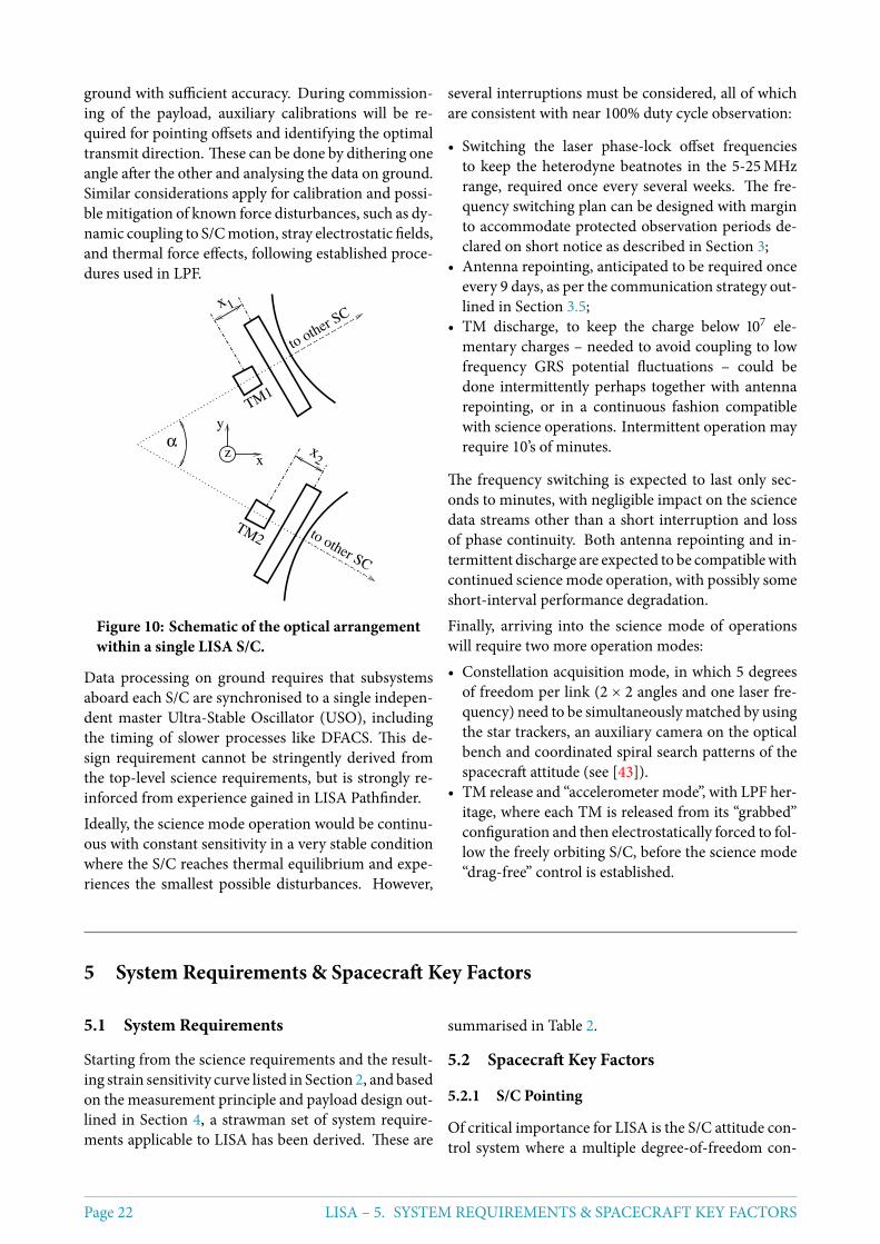
ground with sufficient accuracy. During commission-ing of the payload, auxiliary calibrations will be re-quired for pointing offsets and identifying the optimaltransmit direction. These can be done by dithering oneangle after the other and analysing the data on ground.Similar considerations apply for calibration and possi-ble mitigation of known force disturbances, such as dy-namic coupling to S/Cmotion, stray electrostatic fields,and thermal force effects, following established proce-dures used in LPF.
zx
y
to other SC
to other SC
TM1
TM2
α
x
x
1
2
Figure 10: Schematic of the optical arrangementwithin a single LISA S/C.
Data processing on ground requires that subsystemsaboard each S/C are synchronised to a single indepen-dent master Ultra-Stable Oscillator (USO), includingthe timing of slower processes like DFACS. This de-sign requirement cannot be stringently derived fromthe top-level science requirements, but is strongly re-inforced from experience gained in LISA Pathfinder.Ideally, the science mode operation would be continu-ous with constant sensitivity in a very stable conditionwhere the S/C reaches thermal equilibrium and expe-riences the smallest possible disturbances. However,
several interruptions must be considered, all of whichare consistent with near 100% duty cycle observation:
• Switching the laser phase-lock offset frequenciesto keep the heterodyne beatnotes in the 5-25MHzrange, required once every several weeks. The fre-quency switching plan can be designed with marginto accommodate protected observation periods de-clared on short notice as described in Section 3;
• Antenna repointing, anticipated to be required onceevery 9 days, as per the communication strategy out-lined in Section 3.5;
• TM discharge, to keep the charge below 107 ele-mentary charges – needed to avoid coupling to lowfrequency GRS potential fluctuations – could bedone intermittently perhaps together with antennarepointing, or in a continuous fashion compatiblewith science operations. Intermittent operation mayrequire 10’s of minutes.
The frequency switching is expected to last only sec-onds to minutes, with negligible impact on the sciencedata streams other than a short interruption and lossof phase continuity. Both antenna repointing and in-termittent discharge are expected to be compatiblewithcontinued science mode operation, with possibly someshort-interval performance degradation.Finally, arriving into the science mode of operationswill require two more operation modes:• Constellation acquisition mode, in which 5 degrees
of freedom per link (2 × 2 angles and one laser fre-quency) need to be simultaneouslymatched by usingthe star trackers, an auxiliary camera on the opticalbench and coordinated spiral search patterns of thespacecraft attitude (see [43]).
• TM release and “accelerometer mode”, with LPF her-itage, where each TM is released from its “grabbed”configuration and then electrostatically forced to fol-low the freely orbiting S/C, before the science mode“drag-free” control is established.
5 System Requirements & Spacecraft Key Factors
5.1 System Requirements
Starting from the science requirements and the result-ing strain sensitivity curve listed in Section 2, and basedon the measurement principle and payload design out-lined in Section 4, a strawman set of system require-ments applicable to LISA has been derived. These are
summarised in Table 2.
5.2 Spacecraft Key Factors
5.2.1 S/C Pointing
Of critical importance for LISA is the S/C attitude con-trol system where a multiple degree-of-freedom con-
Page 22 LISA – 5. SYSTEM REQUIREMENTS & SPACECRAFT KEY FACTORS
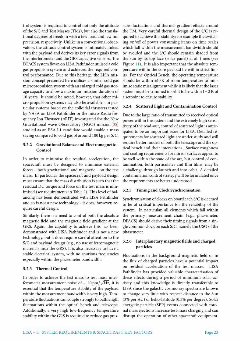
trol system is required to control not only the attitudeof the S/C and Test Masses (TMs), but also the transla-tional degrees of freedom with a few nrad and few nmprecision, respectively. Unlike in a conventional obser-vatory, the attitude control system is intimately linkedwith the payload and derives its key error signals fromthe interferometer and the GRS capacitive sensors. TheDFACS systemflownonLISAPathfinder utilised a coldgas propulsion system and achieved the required con-trol performance. Due to this heritage, the LISA mis-sion concept presented here utilises a similar cold gasmicropropulsion systemwith an enlarged cold gas stor-age capacity to allow a maximum mission duration of10 years. It should be noted, however, that other mi-cro propulsion systems may also be available - in par-ticular systems based on the colloidal thrusters testedby NASA on LISA Pathfinder or the micro-Radio fre-quency Ion Thruster (µRIT) investigated for the NewGravitational wave Observatory (NGO) mission [35]studied as an ESA L1 candidate would enable a masssaving compared to cold gas of around 100 kg per S/C.
5.2.2 Gravitational Balance and ElectromagneticControl
In order to minimise the residual acceleration, thespacecraft must be designed to minimise externalforces - both gravitational and magnetic - on the testmass. In particular the spacecraft and payload designmust ensure that the mass distribution is such that theresidual DC torque and force on the test mass is min-imised (see requirements in Table 2). This level of bal-ancing has been demonstrated with LISA Pathfinderand so is not a new technology - it does, however, re-quire careful design.Similarly, there is a need to control both the absolutemagnetic field and the magnetic field gradient at theGRS. Again, the capability to achieve this has beendemonstrated with LISA Pathfinder and is not a newtechnology, but it does require careful attention to theS/C and payload design (e.g., no use of ferromagneticmaterials near the GRS). It is also necessary to have astable electrical system, with no spurious frequenciesespecially within the phasemeter bandwidth.
5.2.3 Thermal Control
In order to achieve the test mass to test mass inter-ferometer measurement noise of ∼ 10pm/
√Hz, it is
essential that the temperature stability of the payloadwithin the measurement bandwidth is very high. Tem-perature fluctuations can couple strongly to pathlengthfluctuations within the optical bench and telescope.Additionally, a very high low-frequency temperaturestability within the GRS is required to reduce gas pres-
sure fluctuations and thermal gradient effects aroundthe TM. Very careful thermal design of the S/C is re-quired to achieve this stability; for example the switch-ing on/off of power consuming items on time scaleswhich fall within the measurement bandwidth shouldbe avoided and the S/C should remain shaded fromthe sun by its top face (solar panel) at all times (seeFigure 11). It is also important that the absolute tem-perature within the core payload be within strict lim-its. For the Optical Bench, the operating temperatureshould be within ±10K of room temperature to min-imise static misalignment while it is likely that the lasersystem must be trimmed in orbit to be within 1−2K ofa setpoint to ensure stability.
5.2.4 Scattered Light and Contamination Control
Due to the large ratio of transmitted to received opticalpower within the system and the extremely high sensi-tivity of the read-out, control of scattered light is antic-ipated to be an important issue for LISA. Detailed re-quirements for scattered light are under study and willrequire better models of both the telescope and the op-tical bench and their interactions. Surface roughnessand coating requirements for mirror surfaces appear tobe well within the state of the art, but control of con-tamination, both particulates and thin films, may bea challenge through launch and into orbit. A detailedcontamination control strategy will be formulated oncethe requirements are better understood.
5.2.5 Timing and Clock Synchronisation
Synchronisation of clocks on board each S/C is deemedto be of critical importance for the reliability of thesystem. In particular, all elements which fall withinthe primary measurement chain (e.g., phasemeter,DFACS) should derive their timing signals from a sin-gle common clock on each S/C, namely the USO of thephasemeter.
5.2.6 Interplanetary magnetic fields and chargedparticles
Fluctuations in the background magnetic field or inthe flux of charged particles have a potential impacton residual acceleration of the test masses. LISAPathfinder has provided valuable characterisation ofthese effects during a period of minimum solar ac-tivity and this knowledge is directly transferable toLISA since the galactic cosmic-ray spectra are knownto change very little with respect distance to the Sun(3% per AU) or helio-latitude (0.3% per degree). Solarenergetic particle (SEP) events connected with coro-nal mass ejections increase test-mass charging and candisrupt the operation of other spacecraft equipment.
LISA – 5. SYSTEM REQUIREMENTS & SPACECRAFT KEY FACTORS Page 23
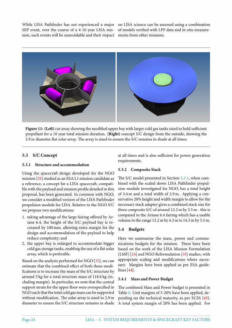
While LISA Pathfinder has not experienced a majorSEP event, over the course of a 4-10 year LISA mis-sion, such events will be unavoidable and their impact
on LISA science can be assessed using a combinationof models verified with LPF data and in-situ measure-ments from other missions.
Figure 11: (Left) cut away showing the modified upper bay with larger cold gas tanks sized to hold sufficientpropellant for a 10 year total mission duration. (Right) concept S/C design from the outside, showing the2.9m diameter flat solar array. The array is sized to ensure the S/C remains in shade at all times.
5.3 S/C Concept
5.3.1 Structure and accommodation
Using the spacecraft design developed for the NGOmission [35] studied as an ESA L1mission candidate asa reference, a concept for a LISA spacecraft, compati-ble with the payload andmission profile detailed in thisproposal, has been generated. In common with NGO,we consider a modified version of the LISA Pathfinderpropulsion module for LISA. Relative to the NGO S/Cwe propose two modifications:1. taking advantage of the large fairing offered by Ar-
iane 6.4, the height of the S/C payload bay is in-creased by 100mm, allowing extra margin for thedesign and accommodation of the payload to helpreduce complexity; and
2. the upper bay is enlarged to accommodate biggercold gas storage tanks, enabling the use of a flat solararray, which is preferable.
Based on the analysis performed for NGO [35], we canestimate that the combined effect of both these modi-fications is to increase the mass of the S/C structure byaround 5 kg for a total structure mass of 118.6 kg (in-cluding margin). In particular, we note that the centralsupport struts for the upper floor were overspecified inNGOsuch that the total cold gasmass can be supportedwithout modification. The solar array is sized to 2.9mdiameter to ensure the S/C structure remains in shade
at all times and is also sufficient for power generationrequirements.
5.3.2 Composite Stack
The S/C model presented in Section 5.3.1, when com-bined with the scaled down LISA Pathfinder propul-sion module investigated for NGO, has a total heightof 3.4m and a total width of 2.9m. Applying a con-servative 20% height and width margin to allow for thenecessary stack adapter gives a combined stack size forthree composite S/C of around 12.2m by 3.5m - this iscompared to the Ariane 6.4 fairing which has a usablevolume in the range 12.2m by 4.3m to 14.3m by 3.5m.
5.4 Budgets
Here we summarise the mass, power and commu-nications budgets for the mission. These have beenbased on the work of the LISA Mission Formulation(LMF) [24] and NGO Reformulation [35] studies, withappropriate scaling and modifications where neces-sary. Margins have been applied as per ESA guide-lines [44].
5.4.1 Mass and Power Budget
The combined Mass and Power budget is presented inTable 6. Unit margins of 5-20% have been applied, de-pending on the technical maturity, as per ECSS [45].A total system margin of 20% has been applied. For
Page 24 LISA – 5. SYSTEM REQUIREMENTS & SPACECRAFT KEY FACTORS
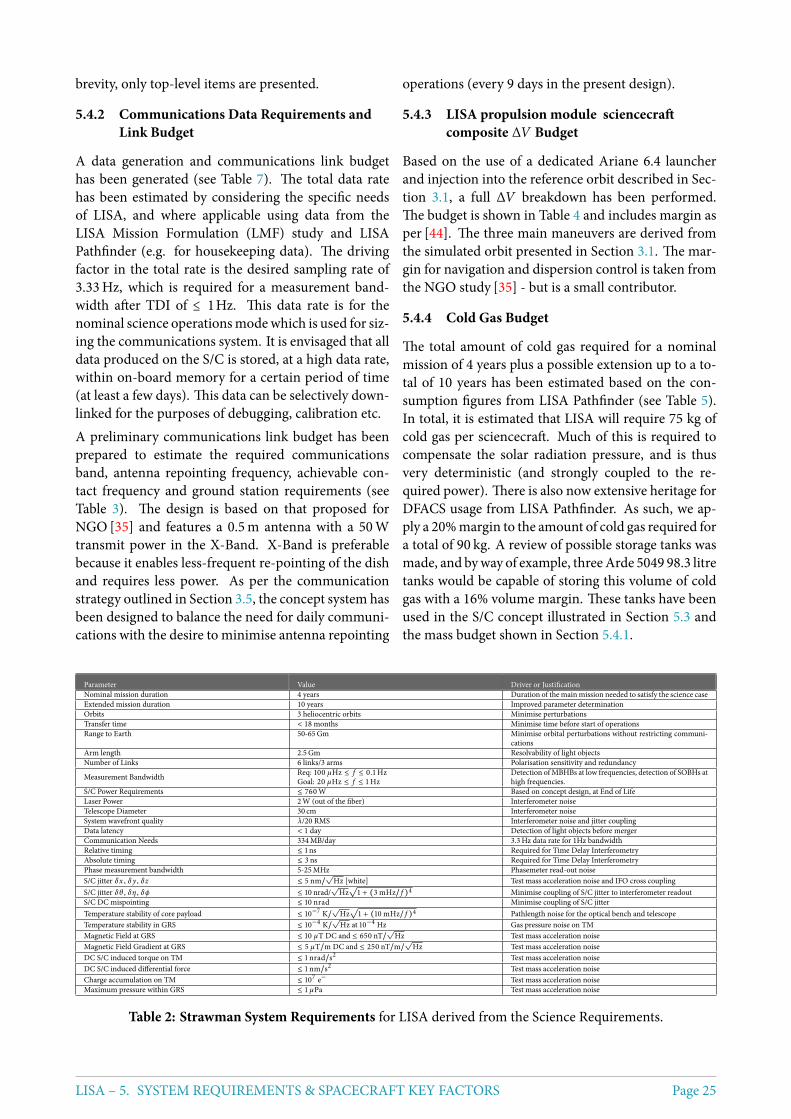
brevity, only top-level items are presented.
5.4.2 Communications Data Requirements andLink Budget
A data generation and communications link budgethas been generated (see Table 7). The total data ratehas been estimated by considering the specific needsof LISA, and where applicable using data from theLISA Mission Formulation (LMF) study and LISAPathfinder (e.g. for housekeeping data). The drivingfactor in the total rate is the desired sampling rate of3.33Hz, which is required for a measurement band-width after TDI of ≤ 1Hz. This data rate is for thenominal science operationsmodewhich is used for siz-ing the communications system. It is envisaged that alldata produced on the S/C is stored, at a high data rate,within on-board memory for a certain period of time(at least a few days). This data can be selectively down-linked for the purposes of debugging, calibration etc.A preliminary communications link budget has beenprepared to estimate the required communicationsband, antenna repointing frequency, achievable con-tact frequency and ground station requirements (seeTable 3). The design is based on that proposed forNGO [35] and features a 0.5m antenna with a 50Wtransmit power in the X-Band. X-Band is preferablebecause it enables less-frequent re-pointing of the dishand requires less power. As per the communicationstrategy outlined in Section 3.5, the concept system hasbeen designed to balance the need for daily communi-cations with the desire to minimise antenna repointing
operations (every 9 days in the present design).
5.4.3 LISA propulsion module sciencecraftcomposite ∆V Budget
Based on the use of a dedicated Ariane 6.4 launcherand injection into the reference orbit described in Sec-tion 3.1, a full ∆V breakdown has been performed.The budget is shown in Table 4 and includes margin asper [44]. The three main maneuvers are derived fromthe simulated orbit presented in Section 3.1. The mar-gin for navigation and dispersion control is taken fromthe NGO study [35] - but is a small contributor.
5.4.4 Cold Gas Budget
The total amount of cold gas required for a nominalmission of 4 years plus a possible extension up to a to-tal of 10 years has been estimated based on the con-sumption figures from LISA Pathfinder (see Table 5).In total, it is estimated that LISA will require 75 kg ofcold gas per sciencecraft. Much of this is required tocompensate the solar radiation pressure, and is thusvery deterministic (and strongly coupled to the re-quired power). There is also now extensive heritage forDFACS usage from LISA Pathfinder. As such, we ap-ply a 20%margin to the amount of cold gas required fora total of 90 kg. A review of possible storage tanks wasmade, and byway of example, threeArde 5049 98.3 litretanks would be capable of storing this volume of coldgas with a 16% volume margin. These tanks have beenused in the S/C concept illustrated in Section 5.3 andthe mass budget shown in Section 5.4.1.
Parameter Value Driver or JustificationNominal mission duration 4 years Duration of themainmission needed to satisfy the science caseExtended mission duration 10 years Improved parameter determinationOrbits 3 heliocentric orbits Minimise perturbationsTransfer time < 18 months Minimise time before start of operationsRange to Earth 50-65Gm Minimise orbital perturbations without restricting communi-
cationsArm length 2.5Gm Resolvability of light objectsNumber of Links 6 links/3 arms Polarisation sensitivity and redundancy
Measurement Bandwidth Req: 100 µHz ≤ f ≤ 0.1 HzGoal: 20 µHz ≤ f ≤ 1 Hz
Detection of MBHBs at low frequencies, detection of SOBHs athigh frequencies.
S/C Power Requirements ≤ 760W Based on concept design, at End of LifeLaser Power 2W (out of the fiber) Interferometer noiseTelescope Diameter 30 cm Interferometer noiseSystem wavefront quality λ/20 RMS Interferometer noise and jitter couplingData latency < 1 day Detection of light objects before mergerCommunication Needs 334MB/day 3.3Hz data rate for 1Hz bandwidthRelative timing ≤ 1 ns Required for Time Delay InterferometryAbsolute timing ≤ 3 ns Required for Time Delay InterferometryPhase measurement bandwidth 5-25MHz Phasemeter read-out noiseS/C jitter δx , δ y , δz ≤ 5 nm/
√Hz [white] Test mass acceleration noise and IFO cross coupling
S/C jitter δθ , δη , δϕ ≤ 10 nrad/√
Hz√
1 + (3mHz/ f )4 Minimise coupling of S/C jitter to interferometer readoutS/C DC mispointing ≤ 10 nrad Minimise coupling of S/C jitterTemperature stability of core payload ≤ 10−7 K/
√Hz√
1 + (10mHz/ f )4 Pathlength noise for the optical bench and telescopeTemperature stability in GRS ≤ 10−4 K/
√Hz at 10−4 Hz Gas pressure noise on TM
Magnetic Field at GRS ≤ 10 µT DC and ≤ 650 nT/√
Hz Test mass acceleration noiseMagnetic Field Gradient at GRS ≤ 5 µT/m DC and ≤ 250 nT/m/
√Hz Test mass acceleration noise
DC S/C induced torque on TM ≤ 1 nrad/s2 Test mass acceleration noiseDC S/C induced differential force ≤ 1 nm/s2 Test mass acceleration noiseCharge accumulation on TM ≤ 107 e− Test mass acceleration noiseMaximum pressure within GRS ≤ 1 µPa Test mass acceleration noise
Table 2: Strawman System Requirements for LISA derived from the Science Requirements.
LISA – 5. SYSTEM REQUIREMENTS & SPACECRAFT KEY FACTORS Page 25
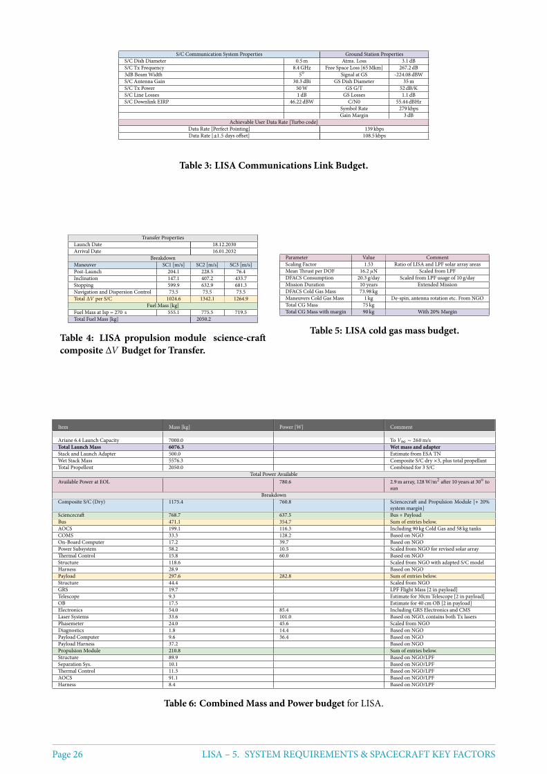
S/C Communication System Properties Ground Station PropertiesS/C Dish Diameter 0.5m Atms. Loss 3.1 dBS/C Tx Frequency 8.4GHz Free Space Loss [65Mkm] 267.2 dB3dB Beam Width 5 Signal at GS -224.08 dBWS/C Antenna Gain 30.3 dBi GS Dish Diameter 35mS/C Tx Power 50W GS G/T 52 dB/KS/C Line Losses 1 dB GS Losses 1.1 dBS/C Downlink EIRP 46.22 dBW C/N0 55.44 dBHz
Symbol Rate 279 kbpsGain Margin 3 dB
Achievable User Data Rate [Turbo code]Data Rate [Perfect Pointing] 139 kbpsData Rate [±1.5 days offset] 108.5 kbps
Table 3: LISA Communications Link Budget.
Transfer PropertiesLaunch Date 18.12.2030Arrival Date 16.01.2032
BreakdownManeuver SC1 [m/s] SC2 [m/s] SC3 [m/s]Post-Launch 204.1 228.5 76.4Inclination 147.1 407.2 433.7Stopping 599.9 632.9 681.3Navigation and Dispersion Control 73.5 73.5 73.5Total ∆V per S/C 1024.6 1342.1 1264.9
Fuel Mass [kg]Fuel Mass at Isp = 270 s 555.1 775.5 719.5Total Fuel Mass [kg] 2050.2
Table 4: LISA propulsion module science-craftcomposite ∆V Budget for Transfer.
Parameter Value CommentScaling Factor 1.53 Ratio of LISA and LPF solar array areasMean Thrust per DOF 16.2 µN Scaled from LPFDFACS Consumption 20.3 g/day Scaled from LPF usage of 10 g/dayMission Duration 10 years Extended MissionDFACS Cold Gas Mass 73.98 kgManeuvers Cold Gas Mass 1 kg De-spin, antenna rotation etc. From NGOTotal CG Mass 75 kgTotal CG Mass with margin 90 kg With 20% Margin
Table 5: LISA cold gas mass budget.
Item Mass [kg] Power [W] Comment
Ariane 6.4 Launch Capacity 7000.0 To V∞ ∼ 260m/sTotal Launch Mass 6076.3 Wet mass and adapterStack and Launch Adapter 500.0 Estimate from ESA TNWet Stack Mass 5576.3 Composite S/C dry ×3, plus total propellantTotal Propellent 2050.0 Combined for 3 S/C
Total Power AvailableAvailable Power at EOL 780.6 2.9m array, 128W/m2 after 10 years at 30 to
sunBreakdown
Composite S/C (Dry) 1175.4 760.8 Sciencecraft and Propulsion Module [+ 20%system margin]
Sciencecraft 768.7 637.5 Bus + PayloadBus 471.1 354.7 Sum of entries below.AOCS 199.1 116.3 Including 90 kg Cold Gas and 58 kg tanksCOMS 33.3 128.2 Based on NGOOn-Board Computer 17.2 39.7 Based on NGOPower Subsystem 58.2 10.5 Scaled from NGO for revised solar arrayThermal Control 15.8 60.0 Based on NGOStructure 118.6 Scaled from NGO with adapted S/C modelHarness 28.9 Based on NGOPayload 297.6 282.8 Sum of entries below.Structure 44.4 Scaled from NGOGRS 19.7 LPF Flight Mass [2 in payload]Telescope 9.3 Estimate for 30cm Telescope [2 in payload]OB 17.5 Estimate for 40 cm OB [2 in payload]Electronics 54.0 85.4 Including GRS Electronics and CMSLaser Systems 33.6 101.0 Based on NGO, contains both Tx lasersPhasemeter 24.0 45.6 Scaled from NGODiagnostics 1.8 14.4 Based on NGOPayload Computer 9.6 36.4 Based on NGOPayload Harness 37.2 Based on NGOPropulsion Module 210.8 Sum of entries below.Structure 89.9 Based on NGO/LPFSeparation Sys. 10.1 Based on NGO/LPFThermal Control 11.3 Based on NGO/LPFAOCS 91.1 Based on NGO/LPFHarness 8.4 Based on NGO/LPF
Table 6: Combined Mass and Power budget for LISA.
Page 26 LISA – 5. SYSTEM REQUIREMENTS & SPACECRAFT KEY FACTORS
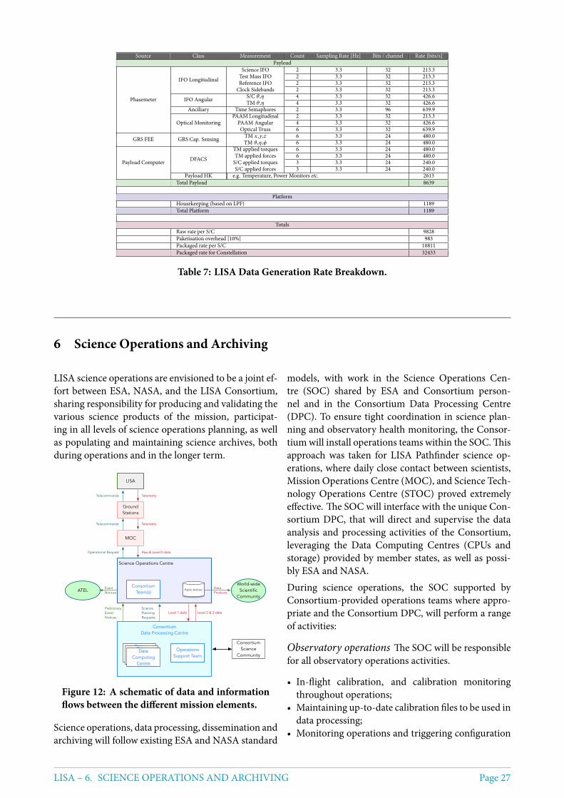
Source Class Measurement Count Sampling Rate [Hz] Bits / channel Rate [bits/s]Payload
Phasemeter
IFO Longitudinal
Science IFO 2 3.3 32 213.3Test Mass IFO 2 3.3 32 213.3Reference IFO 2 3.3 32 213.3
Clock Sidebands 2 3.3 32 213.3
IFO Angular S/C θ ,η 4 3.3 32 426.6TM θ ,η 4 3.3 32 426.6
Anciliary Time Semaphores 2 3.3 96 639.9
Optical MonitoringPAAM Longitudinal 2 3.3 32 213.3
PAAM Angular 4 3.3 32 426.6Optical Truss 6 3.3 32 639.9
GRS FEE GRS Cap. Sensing TM x ,y,z 6 3.3 24 480.0TM θ ,η,ϕ 6 3.3 24 480.0
Payload Computer DFACS
TM applied torques 6 3.3 24 480.0TM applied forces 6 3.3 24 480.0S/C applied torques 3 3.3 24 240.0S/C applied forces 3 3.3 24 240.0
Payload HK e.g. Temperature, Power Monitors etc. 2613Total Payload 8639
PlatformHousekeeping (based on LPF) 1189Total Platform 1189
TotalsRaw rate per S/C 9828Paketisation overhead [10%] 983Packaged rate per S/C 10811Packaged rate for Constellation 32433
Table 7: LISA Data Generation Rate Breakdown.
6 Science Operations and Archiving
LISA science operations are envisioned to be a joint ef-fort between ESA, NASA, and the LISA Consortium,sharing responsibility for producing and validating thevarious science products of the mission, participat-ing in all levels of science operations planning, as wellas populating and maintaining science archives, bothduring operations and in the longer term.
LISA
Ground Stations
MOC
Consortium Team(s)
Science Operations Centre
Public Archive
World-wideScientific
Community
Consortium Data Processing Centre
Data Processing
Centre
Data Processing
Centre
Data Computing
Centre
ATEL
Operations Support Team
Raw & Level 0 dataOperational Request
TelemetryTelecommands
TelemetryTelecommands
EventNotices
Data Products
PreliminaryEventNotices
Level 1 data Level 2 & 3 dataScience Planning Requests
Consortium Science
Community
Figure 12: A schematic of data and informationflows between the different mission elements.
Science operations, data processing, dissemination andarchiving will follow existing ESA and NASA standard
models, with work in the Science Operations Cen-tre (SOC) shared by ESA and Consortium person-nel and in the Consortium Data Processing Centre(DPC). To ensure tight coordination in science plan-ning and observatory health monitoring, the Consor-tium will install operations teams within the SOC. Thisapproach was taken for LISA Pathfinder science op-erations, where daily close contact between scientists,Mission Operations Centre (MOC), and Science Tech-nology Operations Centre (STOC) proved extremelyeffective. The SOC will interface with the unique Con-sortium DPC, that will direct and supervise the dataanalysis and processing activities of the Consortium,leveraging the Data Computing Centres (CPUs andstorage) provided by member states, as well as possi-bly ESA and NASA.During science operations, the SOC supported byConsortium-provided operations teams where appro-priate and the Consortium DPC, will perform a rangeof activities:
Observatory operations The SOC will be responsiblefor all observatory operations activities.
• In-flight calibration, and calibration monitoringthroughout operations;
• Maintaining up-to-date calibration files to be used indata processing;
• Monitoring operations and triggering configuration
LISA – 6. SCIENCE OPERATIONS AND ARCHIVING Page 27
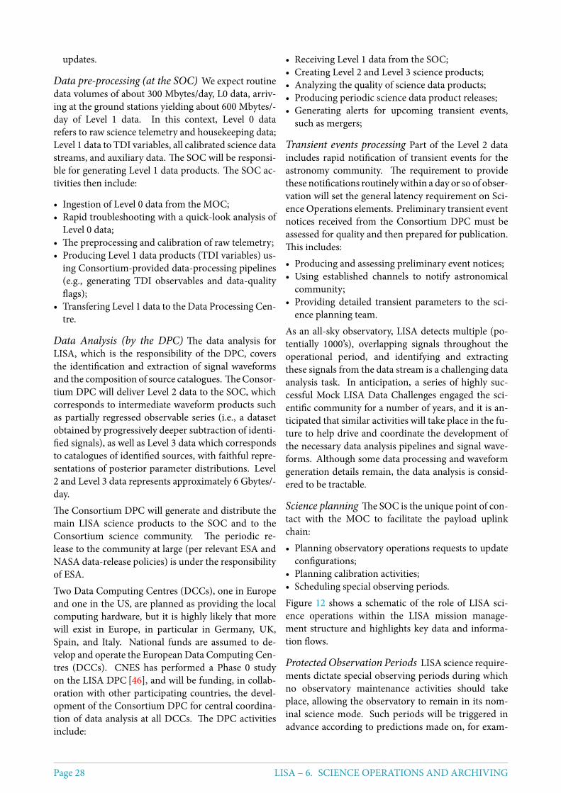
updates.
Data pre-processing (at the SOC) We expect routinedata volumes of about 300 Mbytes/day, L0 data, arriv-ing at the ground stations yielding about 600 Mbytes/-day of Level 1 data. In this context, Level 0 datarefers to raw science telemetry and housekeeping data;Level 1 data to TDI variables, all calibrated science datastreams, and auxiliary data. The SOC will be responsi-ble for generating Level 1 data products. The SOC ac-tivities then include:
• Ingestion of Level 0 data from the MOC;• Rapid troubleshooting with a quick-look analysis of
Level 0 data;• The preprocessing and calibration of raw telemetry;• Producing Level 1 data products (TDI variables) us-
ing Consortium-provided data-processing pipelines(e.g., generating TDI observables and data-qualityflags);
• Transfering Level 1 data to the Data Processing Cen-tre.
Data Analysis (by the DPC) The data analysis forLISA, which is the responsibility of the DPC, coversthe identification and extraction of signal waveformsand the composition of source catalogues. TheConsor-tium DPC will deliver Level 2 data to the SOC, whichcorresponds to intermediate waveform products suchas partially regressed observable series (i.e., a datasetobtained by progressively deeper subtraction of identi-fied signals), as well as Level 3 data which correspondsto catalogues of identified sources, with faithful repre-sentations of posterior parameter distributions. Level2 and Level 3 data represents approximately 6 Gbytes/-day.The Consortium DPC will generate and distribute themain LISA science products to the SOC and to theConsortium science community. The periodic re-lease to the community at large (per relevant ESA andNASA data-release policies) is under the responsibilityof ESA.Two Data Computing Centres (DCCs), one in Europeand one in the US, are planned as providing the localcomputing hardware, but it is highly likely that morewill exist in Europe, in particular in Germany, UK,Spain, and Italy. National funds are assumed to de-velop and operate the European Data Computing Cen-tres (DCCs). CNES has performed a Phase 0 studyon the LISA DPC [46], and will be funding, in collab-oration with other participating countries, the devel-opment of the Consortium DPC for central coordina-tion of data analysis at all DCCs. The DPC activitiesinclude:
• Receiving Level 1 data from the SOC;• Creating Level 2 and Level 3 science products;• Analyzing the quality of science data products;• Producing periodic science data product releases;• Generating alerts for upcoming transient events,
such as mergers;
Transient events processing Part of the Level 2 dataincludes rapid notification of transient events for theastronomy community. The requirement to providethese notifications routinelywithin a day or so of obser-vation will set the general latency requirement on Sci-ence Operations elements. Preliminary transient eventnotices received from the Consortium DPC must beassessed for quality and then prepared for publication.This includes:• Producing and assessing preliminary event notices;• Using established channels to notify astronomical
community;• Providing detailed transient parameters to the sci-
ence planning team.As an all-sky observatory, LISA detects multiple (po-tentially 1000’s), overlapping signals throughout theoperational period, and identifying and extractingthese signals from the data stream is a challenging dataanalysis task. In anticipation, a series of highly suc-cessful Mock LISA Data Challenges engaged the sci-entific community for a number of years, and it is an-ticipated that similar activities will take place in the fu-ture to help drive and coordinate the development ofthe necessary data analysis pipelines and signal wave-forms. Although some data processing and waveformgeneration details remain, the data analysis is consid-ered to be tractable.
Science planning The SOC is the unique point of con-tact with the MOC to facilitate the payload uplinkchain:• Planning observatory operations requests to update
configurations;• Planning calibration activities;• Scheduling special observing periods.Figure 12 shows a schematic of the role of LISA sci-ence operations within the LISA mission manage-ment structure and highlights key data and informa-tion flows.
ProtectedObservation Periods LISA science require-ments dictate special observing periods during whichno observatory maintenance activities should takeplace, allowing the observatory to remain in its nom-inal science mode. Such periods will be triggered inadvance according to predictions made on, for exam-
Page 28 LISA – 6. SCIENCE OPERATIONS AND ARCHIVING
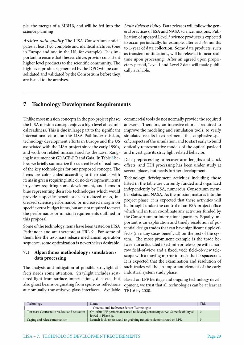
ple, the merger of a MBHB, and will be fed into thescience planning
Archive data quality The LISA Consortium antici-pates at least two complete and identical archives (onein Europe and one in the US, for example). It is im-portant to ensure that these archives provide consistenthigher level products to the scientific community. Thehigh level products generated by the DPC will be con-solidated and validated by the Consortium before theyare issued to the archives.
Data Release Policy Data releases will follow the gen-eral practices of ESA andNASA sciencemissions. Pub-lication of updated Level 3 science products is expectedto occur periodically, for example, after each 6-monthsto 1-year of data collection. Some data products, suchas transient notifications, will be released in near real-time upon processing. After an agreed upon propri-etary period, Level 1 and Level 2 data will made publi-cally available.
7 Technology Development Requirements
Unlikemost mission concepts in the pre-project phase,the LISA mission concept enjoys a high level of techni-cal readiness. This is due in large part to the significantinternational effort on the LISA Pathfinder mission,technology development efforts in Europe and the USassociated with the LISA project since the early 1990s,and work on related missions such as the Laser Rang-ing Instrument onGRACE-FOandGaia. InTable 8 be-low, we briefly summarize the current level of readinessof the key technologies for our proposed concept. Theitems are color-coded according to their status withitems in green requiring little or no development, itemsin yellow requiring some development, and items inblue representing desirable technologies which wouldprovide a specific benefit such as reduced mass, in-creased science performance, or increased margin onspecific error budget items, but are not required tomeetthe performance or mission requirements outlined inthis proposal.Some of the technology items have been tested on LISAPathfinder and are therefore at TRL 9. For some ofthem, like the test-mass release mechanism operationsequence, some optimization is nevertheless desirable.
7.1 Algorithms/ methodology / simulation /data processing
The analysis and mitigation of possible straylight ef-fects needs some attention. Straylight includes scat-tered light from surface imperfections, dust etc., butalso ghost beams originating from spurious reflectionsat nominally transmissive glass interfaces. Available
commercial tools do not normally provide the requiredanswers. Therefore, an intensive effort is required toimprove the modeling and simulation tools, to verifysimulated results in experiments that emphasize spe-cific aspects of the simulation, and to start early to buildoptically representative models of the optical payloadand investigate its stray light related behavior.Data preprocessing to recover arm lengths and clockoffsets, and TDI processing has been under study atseveral places, but needs further development.Technology development activities including thoselisted in the table are currently funded and organizedindependently by ESA, numerous Consortium mem-ber states, and NASA. As the mission matures into theproject phase, it is expected that these activities willbe brought under the control of an ESA project officewhich will in turn coordinate any activities funded bythe Consortium or international partners. Equally im-portant is an exploration and timely resolution of po-tential design trades that can have significant ripple ef-fects (in many cases beneficial) on the rest of the sys-tem. The most prominent example is the trade be-tween an articulated fixed-mirror telescope with a nar-row field-of-view and a fixed, wide field-of-view tele-scope with a moving mirror to track the far spacecraft.It is expected that the examination and resolution ofsuch trades will be an important element of the earlyindustrial system study phase.Based on LPF heritage and ongoing technology devel-opment, we trust that all technologies can be at least atTRL 6 by 2020.
Technology Status TRLGravitational Reference Sensor Technologies
Test mass electrostatic readout and actuation On-orbit LPF performance used to develop sensitivity curve. Some flexibility al-lowed in Phase-A.
9
Caging and release mechanism Launch-lock, release, and re-grabbing functions demonstrated on LPF. 9
LISA – 7. TECHNOLOGY DEVELOPMENT REQUIREMENTS Page 29
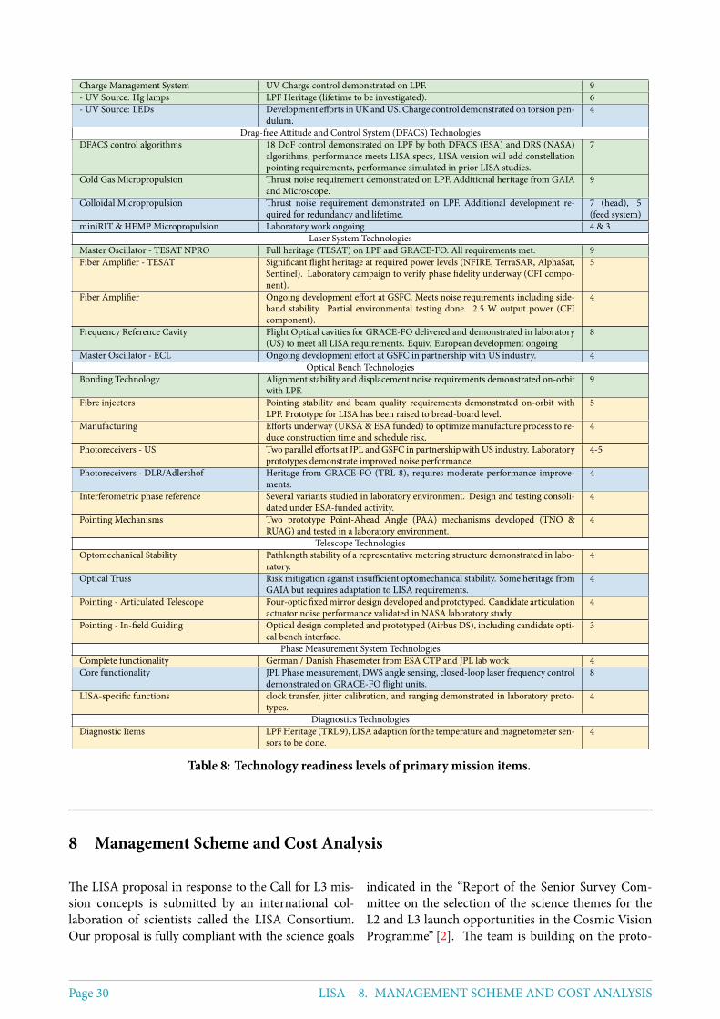
Charge Management System UV Charge control demonstrated on LPF. 9- UV Source: Hg lamps LPF Heritage (lifetime to be investigated). 6- UV Source: LEDs Development efforts inUK andUS. Charge control demonstrated on torsion pen-
dulum.4
Drag-free Attitude and Control System (DFACS) TechnologiesDFACS control algorithms 18 DoF control demonstrated on LPF by both DFACS (ESA) and DRS (NASA)
algorithms, performance meets LISA specs, LISA version will add constellationpointing requirements, performance simulated in prior LISA studies.
7
Cold Gas Micropropulsion Thrust noise requirement demonstrated on LPF. Additional heritage from GAIAand Microscope.
9
Colloidal Micropropulsion Thrust noise requirement demonstrated on LPF. Additional development re-quired for redundancy and lifetime.
7 (head), 5(feed system)
miniRIT & HEMP Micropropulsion Laboratory work ongoing 4 & 3Laser System Technologies
Master Oscillator - TESAT NPRO Full heritage (TESAT) on LPF and GRACE-FO. All requirements met. 9Fiber Amplifier - TESAT Significant flight heritage at required power levels (NFIRE, TerraSAR, AlphaSat,
Sentinel). Laboratory campaign to verify phase fidelity underway (CFI compo-nent).
5
Fiber Amplifier Ongoing development effort at GSFC. Meets noise requirements including side-band stability. Partial environmental testing done. 2.5 W output power (CFIcomponent).
4
Frequency Reference Cavity Flight Optical cavities for GRACE-FO delivered and demonstrated in laboratory(US) to meet all LISA requirements. Equiv. European development ongoing
8
Master Oscillator - ECL Ongoing development effort at GSFC in partnership with US industry. 4Optical Bench Technologies
Bonding Technology Alignment stability and displacement noise requirements demonstrated on-orbitwith LPF.
9
Fibre injectors Pointing stability and beam quality requirements demonstrated on-orbit withLPF. Prototype for LISA has been raised to bread-board level.
5
Manufacturing Efforts underway (UKSA & ESA funded) to optimize manufacture process to re-duce construction time and schedule risk.
4
Photoreceivers - US Two parallel efforts at JPL andGSFC in partnership with US industry. Laboratoryprototypes demonstrate improved noise performance.
4-5
Photoreceivers - DLR/Adlershof Heritage from GRACE-FO (TRL 8), requires moderate performance improve-ments.
4
Interferometric phase reference Several variants studied in laboratory environment. Design and testing consoli-dated under ESA-funded activity.
4
Pointing Mechanisms Two prototype Point-Ahead Angle (PAA) mechanisms developed (TNO &RUAG) and tested in a laboratory environment.
4
Telescope TechnologiesOptomechanical Stability Pathlength stability of a representative metering structure demonstrated in labo-
ratory.4
Optical Truss Risk mitigation against insufficient optomechanical stability. Some heritage fromGAIA but requires adaptation to LISA requirements.
4
Pointing - Articulated Telescope Four-optic fixedmirror design developed and prototyped. Candidate articulationactuator noise performance validated in NASA laboratory study.
4
Pointing - In-field Guiding Optical design completed and prototyped (Airbus DS), including candidate opti-cal bench interface.
3
Phase Measurement System TechnologiesComplete functionality German / Danish Phasemeter from ESA CTP and JPL lab work 4Core functionality JPL Phase measurement, DWS angle sensing, closed-loop laser frequency control
demonstrated on GRACE-FO flight units.8
LISA-specific functions clock transfer, jitter calibration, and ranging demonstrated in laboratory proto-types.
4
Diagnostics TechnologiesDiagnostic Items LPFHeritage (TRL 9), LISA adaption for the temperature andmagnetometer sen-
sors to be done.4
Table 8: Technology readiness levels of primary mission items.
8 Management Scheme and Cost Analysis
The LISA proposal in response to the Call for L3 mis-sion concepts is submitted by an international col-laboration of scientists called the LISA Consortium.Our proposal is fully compliant with the science goals
indicated in the “Report of the Senior Survey Com-mittee on the selection of the science themes for theL2 and L3 launch opportunities in the Cosmic VisionProgramme” [2]. The team is building on the proto-
Page 30 LISA – 8. MANAGEMENT SCHEME AND COST ANALYSIS
consortium that proposed a Gravitational Wave ob-servatory for the L1 flight opportunity, but has beengrowing considerably. It is augmented by additionalmember states and the US as international partner.The LISA Consortium also proposedTheGravitationalUniverse [3] as a science theme for the selection of theL2 and L3 launch opportunity and submitted the per-tinent White Paper. The LISA Consortium also com-prises all the investigators who have successfully pur-sued the LISA Pathfinder mission, a number of scien-tists who worked on the ground-based LIGO, Virgo,and GEO projects, and the Laser Ranging Interferom-eter on the GRACE Follow-On mission, thus makingfull use of all the expertise that has accumulated. Thisapproach optimises the utilisation of the remainingtime for mission preparation and technology develop-ment. We expect all mission elements to be at least atTRL 6 around 2020.Recognizing that on LISA all aspects of the missionperformance are inseparable and have to be studiedand coordinated centrally from the three-satellite con-stellation down to rather low level in the payload, werecommend a strict top-down approach, with ESA ap-pointing a single prime contractor to take responsibil-ity for the payload as well as the S/C. For the same rea-sons we also foresee ESA setting up a System Engineer-ing Office for the entire mission including the core sci-entific instrumentation, providing top-level overviewof all mission aspects including the payload. This of-fice gives close guidance to the Payload CoordinationTeam provided by the Consortium. The Consortiumwill support the ESA System Engineering Office withkey personnel providing expert knowledge on the crit-ical aspect of the detector, including that gathered fromLISA Pathfinder, as requested by ESA.The Consortium will also deliver to ESA the integratedscience instrument at the heart of the payload, plus sev-eral spacecraft-mounted parts of the instrument. It isexpected that the remaining parts of the payload, inparticular lasers and telescopes, will be procured byESA or provided by NASA.The LISA Science Instrument will comprise the opti-cal bench with attached GRS and detached Phasemeterand Data and Diagnostics Subsystem (DDS) plus thesupporting electronics, comprising the GRS Front-endElectronics, Charge Management System, Caging sys-tem, and Data Management Unit (DMU). The instru-ment will be funded by the European member states,with likely contributions from NASA.The distribution of tasks in the Consortium and thecommitments to deliver various pieces of flight hard-ware, ground support equipment, data processing,
and integration tasks will closely follow the prelim-inary declarations of intent brought forward by themember states during the past meetings of the ESA-appointed Gravitational Wave Observatory WorkingGroup (GW-WG).Germany has the lead role in the Consortium and pro-vides the Consortium management, System Engineer-ing for the instrument under the lead of the ESA Mis-sion System Engineering office, and the Phasemeter(PM) system, including USO and Frequency Distri-bution System, with possible contributions from theNetherlands, Belgium, Switzerland, Denmark and/orNASA. France takes the responsibility for integrationand performance control of the Science Instrument,and provides System Engineering support to Germanyon these aspects. France participates in the provi-sion of the Instrument mounting structure with a de-tailed contribution depending on the results and therecommended design from the forthcoming Phase A.France also provides the DPC for the mission. Italywill be responsible for delivering the integrated andtested Gravitational Reference Sensor, that includes theTest Mass, the Electrode Housing, the Vacuum Con-tainer, the Gravitational Balance Masses, the ChargeManagement System, the Caging Mechanism (Swisscontribution), and the Front-End Electronics (Swisscontribution). Italy will also support Germany withsystem engineering aspects that involve GRS and ac-celeration disturbance aspects. The UK provides theassembled optical benches, and will provide SystemEngineering support to Germany on aspects involv-ing the metrology system performance and payloadalignment. Switzerland provides the Front-End Elec-tronics and the Caging Mechanism for the GRS. Spainprovides the DDS including the DMU and electron-ics. Denmark provides contributions to the Phaseme-ter system. Belgium provides the acquisition sensorson the optical benches and the photoreceivers compris-ing photodiodes and front ends. The Netherlands pro-vide electronics for the photoreceivers and possibly theactuators on the optical benches. Swedenwill lend sup-port to the data processing and analysis. Portugal willprovide elements of the data analysis and the qualifi-cation of optical and electronic components. Hungarywill provide elements of the data analysis.The Consortium is proposing that NASA provide di-rectly to ESA further parts of the payload and thespacecraft. There may also be NASA contributions tothe Consortium. The total NASA contribution is ex-pected to be at a level of 20% of the total mission cost.All elements proposed to be provided by our interna-tional partner have potential back-up solutions basedon European technology.
LISA – 8. MANAGEMENT SCHEME AND COST ANALYSIS Page 31
The Consortium will deliver the integrated, tested andaligned LISA instrument to the ESA P/L contractor,who will in turn integrate the Instrument and the ESA-procured or NASA-provided telescope and laser tocomplete the payload.
8.1 LISA Consortium Organisation, Rolesand Responsibilities
8.1.1 LISA Consortium
The LISA Consortium is based on 12 Europeancountries and the US, currently representing morethan 300 scientists as Consortium members (https://www.lisamission.org/consortium/) andmorethan 1300 researchers as supporters (https://www.lisamission.org/supporters/). The ConsortiumBoard comprises one or two representatives from eachcountry as the Co-Investigators. It is the final decisionmaking body and is responsible for the implementa-tion in the participating countries. Top-level opera-tions are coordinated by the Executive Board which isled by the Consortium Lead as the single point of con-tact with ESA.
8.1.2 Top Level Organisation in Phase A/B
Figure 13 illustrates the top-level organisation of theLISA Consortium and project during the Phase-A/B ofthe project. The organisation is optimized to supportthe study activities during this mission phase and over-seeing the technology development activities.The LISA Consortium is led by the PI, called LISAConsortium Lead (LCL), supported in its top manage-ment function by the Executive Board consisting of theConsortium Lead (Karsten Danzmann) and five Co-PIs, one for Science (Pierre Binetruy), one for LISAPathfinder (Stefano Vitale), one for the optical metrol-ogy (Henry Ward), one as liaison to the other memberstates (Domenico Giardini), and one as liaison to theUS community (David Shoemaker). The compositionof the Executive Board will be adapted to the changingproject needs. The LISA Consortium Lead is the singleformal interface of the Consortium with ESAThe scientific community is represented in the LISAConsortium Board, comprising Co-Investigators asrepresentatives per participating country. The Consor-tiumBoard is the final decisionmaking body andmeetsat least four times per year.The Consortium Lead receives scientific supervisionand advice on scientific matters from the Science StudyTeam comprising scientists from the international sci-entific community, appointed by ESA and chaired bythe ESA Project Scientist. The ESA Science Study Teamis responsible for the definition of the mission scien-
tific requirements that are recorded within the ScienceRequirement Document (ScRD) and for ensuring thatthe implementation of S/C, P/L, instrument, and unitsof LISA fulfills these scientific requirements.The Consortium Lead is supported in this manage-ment function by the Payload Coordination Team, theGround Segment Coordination Team, and the ScienceCoordination Team, each led by a Team Coordinator.Close guidance to the Payload Coordination Team isgiven by the ESA Systems Engineering Office. The Sys-tems Engineering Office is an ESA function provid-ing top-level overview of all mission aspects includ-ing the payload, recognizing that on LISA all aspectsof the mission performance are inseparable and haveto be studied and coordinated centrally down to ratherlow level in the payload. The Consortium will pro-vide members to the Systems Engineering Office as re-quested by ESA. NASA will also contribute to the Sys-tems Engineering.The ESA Steering Committee is the representation ofthe participating funding agencies of the ESA MemberStates and NASA, and responsible for the final decisionabout financial implications at the national level.
LISA Consortium Board
The role of the LISA Consortium Board is to definethe Consortium policy with respect to the Consortiummanagement and the scientific objectives. TheConsor-tium Board steers the activities of the Consortium inthe involved countries, it confirms the members of theExecutive Board in agreement with ESA and the Steer-ing Committee, and delegates themanagement and thecoordination of the Consortium and the top-level op-erative decisions to the LISA Consortium Lead and theExecutive Board. The Consortium Board also definesthe topics and appoints the conveners of the WorkingGroups, after consultation with the Executive Boardand the Science Coordination Team. The ConsortiumBoard meets at least four times per year.The Consortium Board comprises Co-Investigatorsas representatives per participating country and ischaired by theConsortiumLead. The currentmembersof the Consortium Board are Karsten Danzmann andBernard Schutz (D), Stefano Vitale and Monica Colpi(I), Pierre Binetruy andNaryMan (F), DomenicoGiar-dini and Philippe Jetzer (CH), HarryWard andAlbertoVecchio (UK), Carlos Sopuerta (ES), Allan Hornstrup(DK), Gijs Nelemans (NL), Thomas Hertog (B), Vi-tor Cardoso (PT), Ross Church (SE), Zsolt Frei (HU),David Shoemaker, Neil Cornish, Guido Mueller andShane Larson (US). The membership may be changedto adapt to the evolving project needs.
Page 32 LISA – 8. MANAGEMENT SCHEME AND COST ANALYSIS
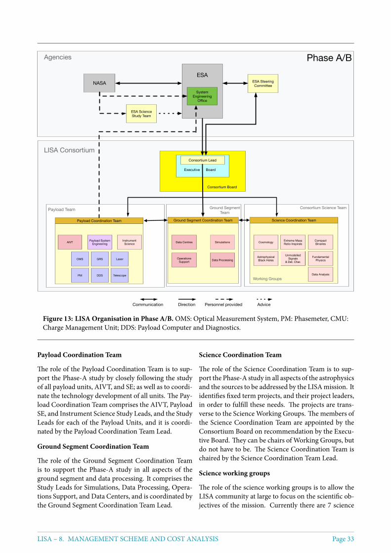
Consortium Science Team
Science Coordination Team
ESA
System Engineering
Office
Payload Team
Payload Coordination Team
LISA Consortium
Agencies
ESA Steering Committee
Ground SegmentTeam
Ground Segment Coordination Team
ESA Science Study Team
NASA
Consortium Board
Cosmology
Astrophysical Black Holes
Data Analysis
Extreme Mass Ratio Inspirals
Fundamental Physics
Compact Binaries
Unmodelled Signals
& Det. Char.
Working Groups
Operations Support Data Processing
Simulations
Executive Board
Data Centres
Phase A/B
Consortium Lead
Personnel providedDirectionCommunication Advice
Instrument Science
Telescope
Laser
DDS
OMS GRS
PM
AIVT Payload System Engineering
Figure 13: LISA Organisation in Phase A/B. OMS: Optical Measurement System, PM: Phasemeter, CMU:Charge Management Unit; DDS: Payload Computer and Diagnostics.
Payload Coordination Team
The role of the Payload Coordination Team is to sup-port the Phase-A study by closely following the studyof all payload units, AIVT, and SE; as well as to coordi-nate the technology development of all units. The Pay-load Coordination Team comprises the AIVT, PayloadSE, and Instrument Science Study Leads, and the StudyLeads for each of the Payload Units, and it is coordi-nated by the Payload Coordination Team Lead.
Ground Segment Coordination Team
The role of the Ground Segment Coordination Teamis to support the Phase-A study in all aspects of theground segment and data processing. It comprises theStudy Leads for Simulations, Data Processing, Opera-tions Support, and Data Centers, and is coordinated bythe Ground Segment Coordination Team Lead.
Science Coordination Team
The role of the Science Coordination Team is to sup-port the Phase-A study in all aspects of the astrophysicsand the sources to be addressed by the LISAmission. Itidentifies fixed term projects, and their project leaders,in order to fulfill these needs. The projects are trans-verse to the Science Working Groups. The members ofthe Science Coordination Team are appointed by theConsortium Board on recommendation by the Execu-tive Board. They can be chairs of Working Groups, butdo not have to be. The Science Coordination Team ischaired by the Science Coordination Team Lead.
Science working groups
The role of the science working groups is to allow theLISA community at large to focus on the scientific ob-jectives of the mission. Currently there are 7 science
LISA – 8. MANAGEMENT SCHEME AND COST ANALYSIS Page 33
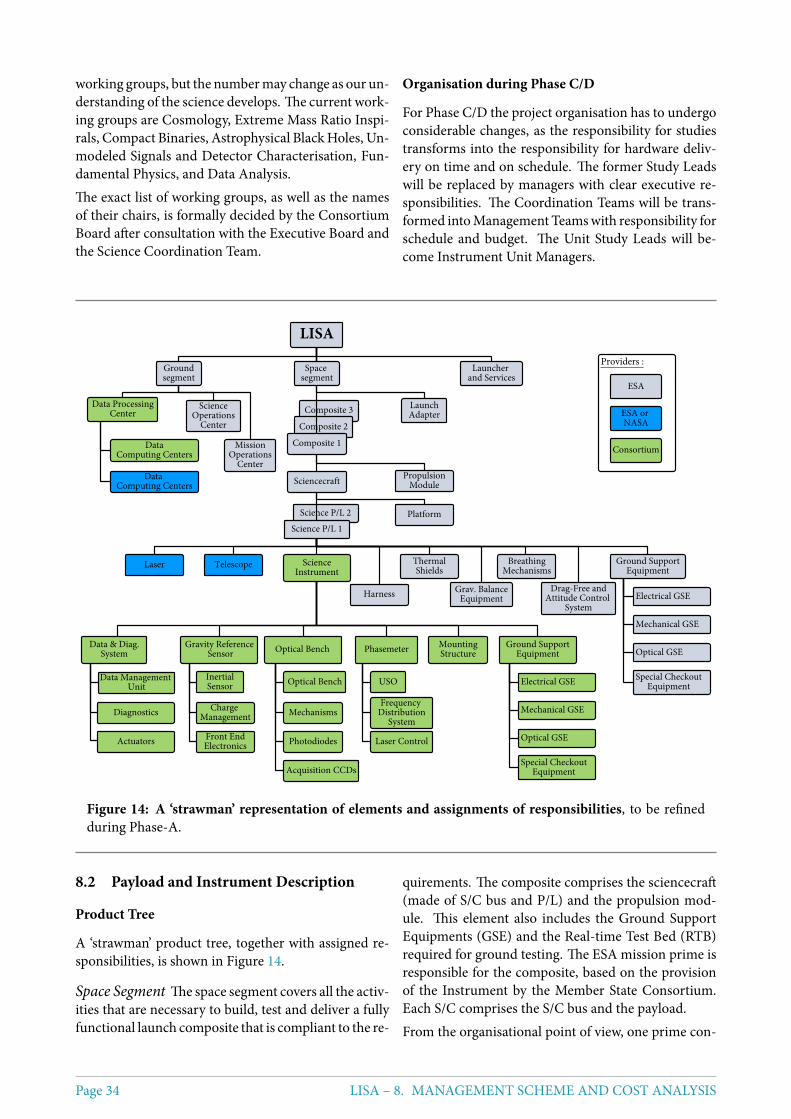
working groups, but the numbermay change as our un-derstanding of the science develops. The current work-ing groups are Cosmology, Extreme Mass Ratio Inspi-rals, Compact Binaries, Astrophysical BlackHoles, Un-modeled Signals and Detector Characterisation, Fun-damental Physics, and Data Analysis.The exact list of working groups, as well as the namesof their chairs, is formally decided by the ConsortiumBoard after consultation with the Executive Board andthe Science Coordination Team.
Organisation during Phase C/D
For Phase C/D the project organisation has to undergoconsiderable changes, as the responsibility for studiestransforms into the responsibility for hardware deliv-ery on time and on schedule. The former Study Leadswill be replaced by managers with clear executive re-sponsibilities. The Coordination Teams will be trans-formed intoManagement Teamswith responsibility forschedule and budget. The Unit Study Leads will be-come Instrument Unit Managers.
Figure 14: A ‘strawman’ representation of elements and assignments of responsibilities, to be refinedduring Phase-A.
8.2 Payload and Instrument Description
Product Tree
A ‘strawman’ product tree, together with assigned re-sponsibilities, is shown in Figure 14.
Space Segment The space segment covers all the activ-ities that are necessary to build, test and deliver a fullyfunctional launch composite that is compliant to the re-
quirements. The composite comprises the sciencecraft(made of S/C bus and P/L) and the propulsion mod-ule. This element also includes the Ground SupportEquipments (GSE) and the Real-time Test Bed (RTB)required for ground testing. The ESA mission prime isresponsible for the composite, based on the provisionof the Instrument by the Member State Consortium.Each S/C comprises the S/C bus and the payload.From the organisational point of view, one prime con-
Page 34 LISA – 8. MANAGEMENT SCHEME AND COST ANALYSIS
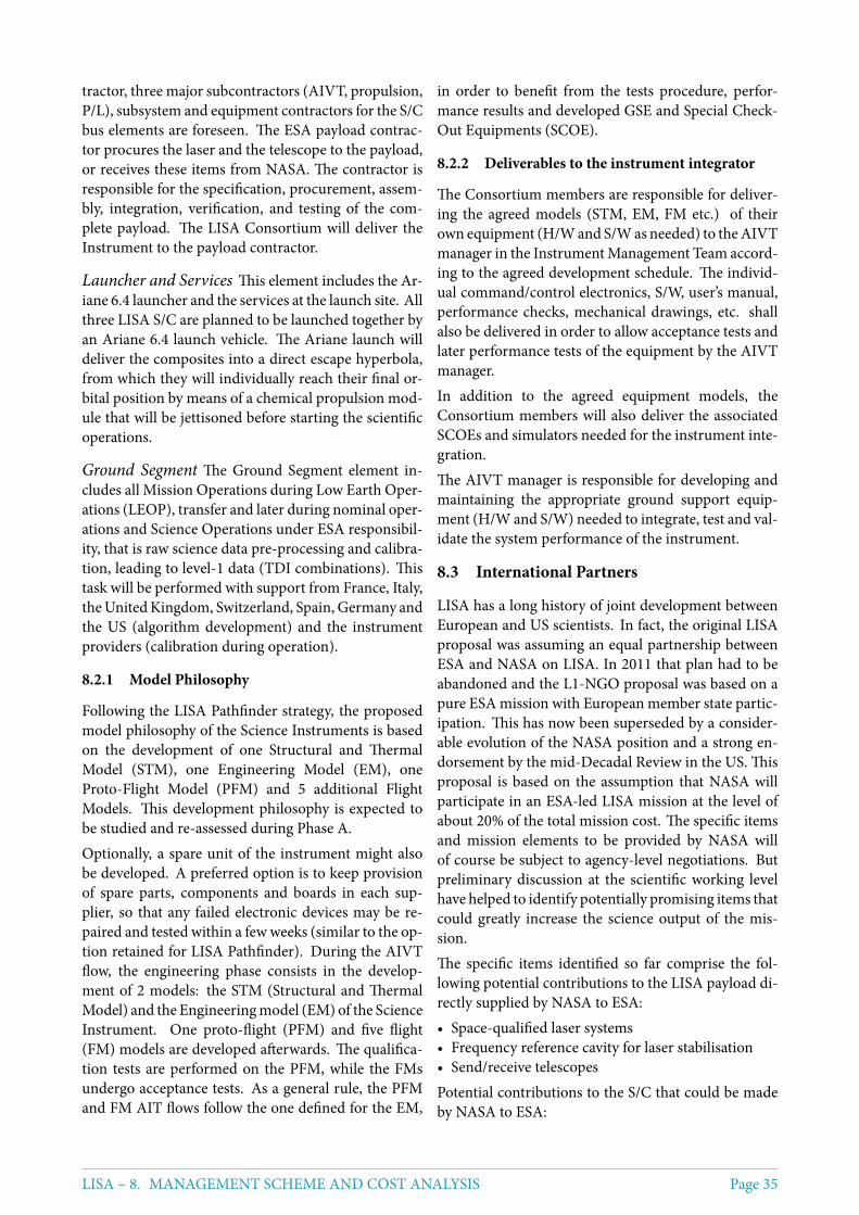
tractor, three major subcontractors (AIVT, propulsion,P/L), subsystem and equipment contractors for the S/Cbus elements are foreseen. The ESA payload contrac-tor procures the laser and the telescope to the payload,or receives these items from NASA. The contractor isresponsible for the specification, procurement, assem-bly, integration, verification, and testing of the com-plete payload. The LISA Consortium will deliver theInstrument to the payload contractor.
Launcher and Services This element includes the Ar-iane 6.4 launcher and the services at the launch site. Allthree LISA S/C are planned to be launched together byan Ariane 6.4 launch vehicle. The Ariane launch willdeliver the composites into a direct escape hyperbola,from which they will individually reach their final or-bital position by means of a chemical propulsion mod-ule that will be jettisoned before starting the scientificoperations.
Ground Segment The Ground Segment element in-cludes all Mission Operations during Low Earth Oper-ations (LEOP), transfer and later during nominal oper-ations and Science Operations under ESA responsibil-ity, that is raw science data pre-processing and calibra-tion, leading to level-1 data (TDI combinations). Thistask will be performed with support from France, Italy,theUnitedKingdom, Switzerland, Spain, Germany andthe US (algorithm development) and the instrumentproviders (calibration during operation).
8.2.1 Model Philosophy
Following the LISA Pathfinder strategy, the proposedmodel philosophy of the Science Instruments is basedon the development of one Structural and ThermalModel (STM), one Engineering Model (EM), oneProto-Flight Model (PFM) and 5 additional FlightModels. This development philosophy is expected tobe studied and re-assessed during Phase A.Optionally, a spare unit of the instrument might alsobe developed. A preferred option is to keep provisionof spare parts, components and boards in each sup-plier, so that any failed electronic devices may be re-paired and tested within a fewweeks (similar to the op-tion retained for LISA Pathfinder). During the AIVTflow, the engineering phase consists in the develop-ment of 2 models: the STM (Structural and ThermalModel) and the Engineeringmodel (EM) of the ScienceInstrument. One proto-flight (PFM) and five flight(FM) models are developed afterwards. The qualifica-tion tests are performed on the PFM, while the FMsundergo acceptance tests. As a general rule, the PFMand FM AIT flows follow the one defined for the EM,
in order to benefit from the tests procedure, perfor-mance results and developed GSE and Special Check-Out Equipments (SCOE).
8.2.2 Deliverables to the instrument integrator
The Consortium members are responsible for deliver-ing the agreed models (STM, EM, FM etc.) of theirown equipment (H/Wand S/Was needed) to theAIVTmanager in the InstrumentManagement Team accord-ing to the agreed development schedule. The individ-ual command/control electronics, S/W, user’s manual,performance checks, mechanical drawings, etc. shallalso be delivered in order to allow acceptance tests andlater performance tests of the equipment by the AIVTmanager.In addition to the agreed equipment models, theConsortium members will also deliver the associatedSCOEs and simulators needed for the instrument inte-gration.The AIVT manager is responsible for developing andmaintaining the appropriate ground support equip-ment (H/W and S/W) needed to integrate, test and val-idate the system performance of the instrument.
8.3 International Partners
LISA has a long history of joint development betweenEuropean and US scientists. In fact, the original LISAproposal was assuming an equal partnership betweenESA and NASA on LISA. In 2011 that plan had to beabandoned and the L1-NGO proposal was based on apure ESA mission with European member state partic-ipation. This has now been superseded by a consider-able evolution of the NASA position and a strong en-dorsement by the mid-Decadal Review in the US. Thisproposal is based on the assumption that NASA willparticipate in an ESA-led LISA mission at the level ofabout 20% of the total mission cost. The specific itemsand mission elements to be provided by NASA willof course be subject to agency-level negotiations. Butpreliminary discussion at the scientific working levelhave helped to identify potentially promising items thatcould greatly increase the science output of the mis-sion.The specific items identified so far comprise the fol-lowing potential contributions to the LISA payload di-rectly supplied by NASA to ESA:• Space-qualified laser systems• Frequency reference cavity for laser stabilisation• Send/receive telescopesPotential contributions to the S/C that could be madeby NASA to ESA:
LISA – 8. MANAGEMENT SCHEME AND COST ANALYSIS Page 35
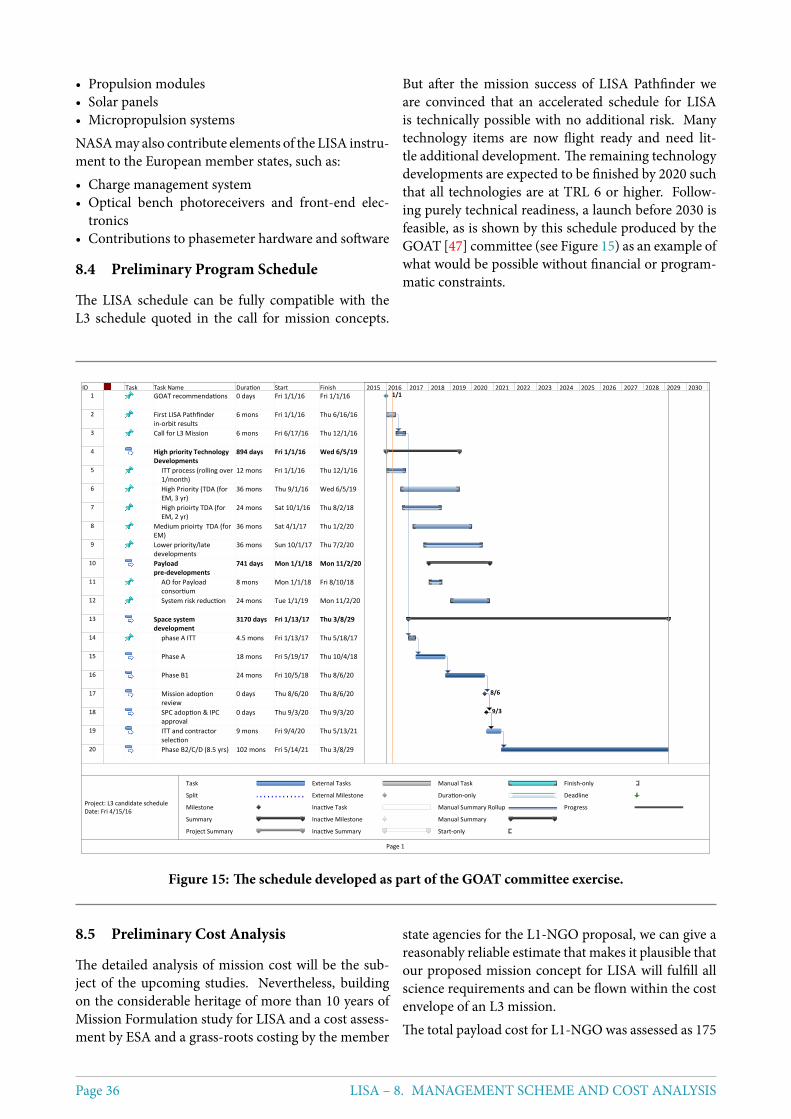
• Propulsion modules• Solar panels• Micropropulsion systemsNASAmay also contribute elements of the LISA instru-ment to the European member states, such as:• Charge management system• Optical bench photoreceivers and front-end elec-
tronics• Contributions to phasemeter hardware and software
8.4 Preliminary Program Schedule
The LISA schedule can be fully compatible with theL3 schedule quoted in the call for mission concepts.
But after the mission success of LISA Pathfinder weare convinced that an accelerated schedule for LISAis technically possible with no additional risk. Manytechnology items are now flight ready and need lit-tle additional development. The remaining technologydevelopments are expected to be finished by 2020 suchthat all technologies are at TRL 6 or higher. Follow-ing purely technical readiness, a launch before 2030 isfeasible, as is shown by this schedule produced by theGOAT [47] committee (see Figure 15) as an example ofwhat would be possible without financial or program-matic constraints.
ID Task Task Name Duration Start Finish1 GOAT recommendations 0 days Fri 1/1/16 Fri 1/1/16
2 First LISA Pathfinder in-orbit results
6 mons Fri 1/1/16 Thu 6/16/16
3 Call for L3 Mission 6 mons Fri 6/17/16 Thu 12/1/16
4 High priority Technology Developments
894 days Fri 1/1/16 Wed 6/5/19
5 ITT process (rolling over 1/month)
12 mons Fri 1/1/16 Thu 12/1/16
6 High Priority (TDA (for EM, 3 yr)
36 mons Thu 9/1/16 Wed 6/5/19
7 High prioirty TDA (for EM, 2 yr)
24 mons Sat 10/1/16 Thu 8/2/18
8 Medium prioirty TDA (for EM)
36 mons Sat 4/1/17 Thu 1/2/20
9 Lower priority/late developments
36 mons Sun 10/1/17 Thu 7/2/20
10 Payload pre-developments
741 days Mon 1/1/18 Mon 11/2/20
11 AO for Payload consortium
8 mons Mon 1/1/18 Fri 8/10/18
12 System risk reduction 24 mons Tue 1/1/19 Mon 11/2/20
13 Space system development
3170 days Fri 1/13/17 Thu 3/8/29
14 phase A ITT 4.5 mons Fri 1/13/17 Thu 5/18/17
15 Phase A 18 mons Fri 5/19/17 Thu 10/4/18
16 Phase B1 24 mons Fri 10/5/18 Thu 8/6/20
17 Mission adoption review
0 days Thu 8/6/20 Thu 8/6/20
18 SPC adoption & IPC approval
0 days Thu 9/3/20 Thu 9/3/20
19 ITT and contractor selection
9 mons Fri 9/4/20 Thu 5/13/21
20 Phase B2/C/D (8.5 yrs) 102 mons Fri 5/14/21 Thu 3/8/29
1/1
8/6
9/3
2015 2016 2017 2018 2019 2020 2021 2022 2023 2024 2025 2026 2027 2028 2029 2030
Task
Split
Milestone
Summary
Project Summary
External Tasks
External Milestone
Inactive Task
Inactive Milestone
Inactive Summary
Manual Task
Duration-only
Manual Summary Rollup
Manual Summary
Start-only
Finish-only
Deadline
Progress
Page 1
Project: L3 candidate scheduleDate: Fri 4/15/16
Figure 15: The schedule developed as part of the GOAT committee exercise.
8.5 Preliminary Cost Analysis
The detailed analysis of mission cost will be the sub-ject of the upcoming studies. Nevertheless, buildingon the considerable heritage of more than 10 years ofMission Formulation study for LISA and a cost assess-ment by ESA and a grass-roots costing by the member
state agencies for the L1-NGO proposal, we can give areasonably reliable estimate that makes it plausible thatour proposed mission concept for LISA will fulfill allscience requirements and can be flown within the costenvelope of an L3 mission.The total payload cost for L1-NGO was assessed as 175
Page 36 LISA – 8. MANAGEMENT SCHEME AND COST ANALYSIS
Me in 2012 economic conditions. Since our baselinemission now entails 6 laser links instead of the 4 as-sumed for NGO, the recurring cost for some memberstates will be somewhat higher, and we estimate the to-tal cost to the member states at 250 Me without mar-gin. This seems within the affordable range for the ESAmember states.The ESA cost at completion (CaC) for the NGO layoutas a strawman design for the L2/L3 Science Theme Se-lection was costed by ESA in 2013 as 1200 Me, assum-ing an Ariane 6 launch and procurement of lasers andtelescopes by ESA. Our current LISA proposal is builton using three identical S/C of the type of the NGOmother S/C, so we can rely on scaling themass, volumeand cost from those numbers. The main differencescome from the slightly larger telescopes and the slightlychanged orbits. Increasing the telescope diameter from20 cm to 30 cm should not change the S/C mass andcost significantly, because that is mainly determined bythe optical bench size as long as the telescope diameterstays below 30 cm. The NGO orbits were drift-awayorbits, limiting the possible extended mission lifetime.We are now asking for a stop manoeuvre at the end ofthe orbit insertion to lower Doppler shifts and breath-ing angles, reducing payload complexity and risk, andmaking a 10 year extended mission feasible. We notethat this only adds a ∆V penalty of a few 100m/s andneeds very little additional fuel, which is well withinthe Ariane 6.4 capabilities. So we expect no noticeablecost penalty from this. Moreover, since we are askingfor three identical S/C for our baseline mission, the ad-ditional non-recurring cost of having two different S/Ctypes in NGO no longer applies to our LISA design.And finally, if NASA provides, for example, lasers, tele-scopes and some other spacecraft and instrument ele-ments, we expect that the cost to ESA will stay well be-low the 1050 Me cost cap for L3 missions.
8.6 Risk analysis
Risk items were identified in the technical and pro-grammatic review of the NGO L1 Mission Study [48],page 12-14. After the successful pathfinder flight,many of the risk items can be retired.The top-level (D4 according to ECSS-M-ST-80C [49])risk (Complexity caused by multiple spacecraft devel-opment will impact schedule and cost), due to systemcomplexity, can now be reduced to a C4 because a)we are using 3 identical spacecraft instead of two typesand b) due to the successful integration of LPF and the
demonstration of gravity gradient control. The nextrisk (C4) (Inability to perform end-to-end testing onthe groundwill result in degradedmission capabilities)can be reduced to a B4 due to the end-to-end demon-stration of success in LPF. The 3rd item (B5)(Failure ofa single GRS system degrades science performance) isretired to B3 because we have 3 instead of 2 arms, andthe GRS has direct flight heritage. There is no quantifi-able change to the risk that loss of one S/Cwill cause theend ofmission. But we intend to study the option to as-semble a full spacecraft flight spare on the ground fromthe various subsystem flight spares. In case of a space-craft failure during the extended mission this could belaunched on demand.The risk that LPFwill fail to demonstrate some in-flightperformance at the required levels or the data cannotbe extrapolated to LISA performance is retired. The(formerly C3) Cold Gas Thrusters have been qualifiedfor the 5-year Gaia performance lifetime. The failureof LPF has been completely retired. The risk (B5) “Ac-quisition of the optical links through the telescopes be-tween spacecraft not achieved” is reduced through theperformance of the differential wavefront sensing onLPF to B3.The risk “PMSeparation results in high spacecraft rota-tion rate” has been retired by test on LPF. The risk thatthere will be “Unexpected thermal fluctuation noisesources degrade residual acceleration performance” isgreatly reduced through LPF performance to A2. Therisk that “Transfer Burns fail to insert spacecraft intofinal orbits” is partly retired due to a successful test onLPF.Remaining notable risks for LISA are under control dueto the ongoing LISA development program. They are:the risk that two different architectures are possible forthe telescope pointing; optical bench series production;straylight and manufacturability of the telescope; andlaser system sideband fidelity.Lastly, we note the risk that the long program durationleads to loss of key and experienced personnel. Thisis best mitigated through an early implementation andearly launch date, and continued robust support fromthe contributing agencies. This will permit transfer ofknowledge in the scientific instrument teams from onegeneration of scientists to the next during the missionlifetime. Assuming early and reliable support from ournational agencies, we are planning to develop a person-nel succession plan for younger scientists supportingthe key people close to retirement.
LISA – 8. MANAGEMENT SCHEME AND COST ANALYSIS Page 37
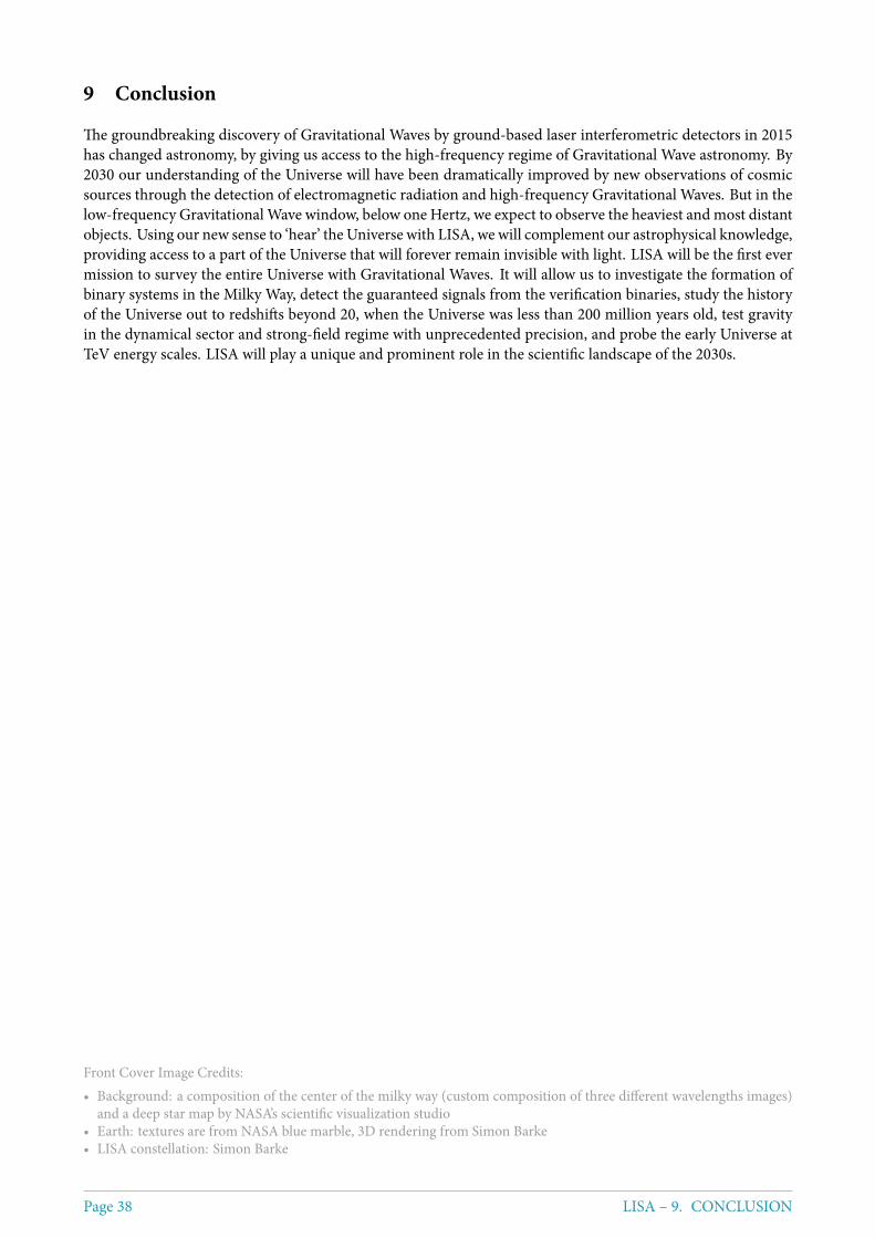
9 Conclusion
The groundbreaking discovery of Gravitational Waves by ground-based laser interferometric detectors in 2015has changed astronomy, by giving us access to the high-frequency regime of Gravitational Wave astronomy. By2030 our understanding of the Universe will have been dramatically improved by new observations of cosmicsources through the detection of electromagnetic radiation and high-frequency Gravitational Waves. But in thelow-frequency Gravitational Wave window, below one Hertz, we expect to observe the heaviest and most distantobjects. Using our new sense to ‘hear’ the Universe with LISA, we will complement our astrophysical knowledge,providing access to a part of the Universe that will forever remain invisible with light. LISA will be the first evermission to survey the entire Universe with Gravitational Waves. It will allow us to investigate the formation ofbinary systems in the Milky Way, detect the guaranteed signals from the verification binaries, study the historyof the Universe out to redshifts beyond 20, when the Universe was less than 200 million years old, test gravityin the dynamical sector and strong-field regime with unprecedented precision, and probe the early Universe atTeV energy scales. LISA will play a unique and prominent role in the scientific landscape of the 2030s.
Front Cover Image Credits:• Background: a composition of the center of the milky way (custom composition of three different wavelengths images)
and a deep star map by NASA’s scientific visualization studio• Earth: textures are from NASA blue marble, 3D rendering from Simon Barke• LISA constellation: Simon Barke
Page 38 LISA – 9. CONCLUSION
References
[1] B. P. Abbott et al., “Observation of Gravitational Waves from a Binary Black Hole Merger,” Phys. Rev. Lett., vol. 116,p. 061102, Feb 2016.
[2] C. Cesarsky and the Senior Survey Committee, “Report of the Senior Survey Committee on the selection of thescience themes for the L2 and L3 launch opportunities in the cosmic vision programme,” http://sci.esa.int/cosmic-vision/53260-report-on-science-themes-for-l2-and-l3-missions, 2013.
[3] K. Danzmann and the LISA Consortium, “The Gravitational Universe,” https://arxiv.org/abs/1305.5720, 2013.
[4] M. Armano et al., “Sub-Femto-g Free Fall for Space-Based Gravitational Wave Observatories: LISA Pathfinder Re-sults,” Phys. Rev. Lett., vol. 116, p. 231101, Jun 2016.
[5] C. J. Moore, R. H. Cole, and C. P. L. Berry, “Gravitational-wave sensitivity curves,” Classical and Quantum Gravity,vol. 32, no. 1, p. 015014, 2015.
[6] G. Nelemans, L. R. Yungelson, and S. F. Portegies Zwart, “The gravitational wave signal from the Galactic disk popu-lation of binaries containing two compact objects,” Astronomy & Astrophysics, vol. 375, pp. 890–898, Sept. 2001.
[7] S. Toonen, G. Nelemans, and S. Portegies Zwart, “Supernova Type Ia progenitors from merging double white dwarfs:Using a new population synthesis model,” Astron. Astrophys., vol. 546, p. A70, 2012.
[8] M. Volonteri, “Formation of supermassive black holes,”TheAstronomy and Astrophysics Review, vol. 18, pp. 279–315,July 2010.
[9] A. Sesana, F. Haardt, P. Madau, and M. Volonteri, “Low-frequency gravitational radiation from coalescing massiveblack hole binaries in hierarchical cosmologies,” The Astrophysical Journal, vol. 611, no. 2, p. 623, 2004.
[10] A. Klein, E. Barausse, A. Sesana, A. Petiteau, E. Berti, S. Babak, J. Gair, S. Aoudia, I. Hinder, F. Ohme, and B. Wardell,“Sciencewith the space-based interferometer eLISA: Supermassive black hole binaries,” Phys. Rev.D, vol. 93, p. 024003,Jan. 2016.
[11] S. F. Portegies Zwart and S. L. W. McMillan, “The Runaway Growth of Intermediate-Mass Black Holes in Dense StarClusters,” The Astrophys. J., vol. 576, pp. 899–907, Sept. 2002.
[12] P. Amaro-Seoane, J. R. Gair, M. Freitag, M. C. Miller, I. Mandel, C. J. Cutler, and S. Babak, “TOPICAL REVIEW:Intermediate and extrememass-ratio inspirals: astrophysics, science applications and detection using LISA,”Classicaland Quantum Gravity, vol. 24, pp. R113–R169, Sept. 2007.
[13] A. Sesana, “Prospects for Multiband Gravitational-Wave Astronomy after GW150914,” Physical Review Letters,vol. 116, p. 231102, June 2016.
[14] E. Berti, V. Cardoso, and C. M. Will, “Gravitational-wave spectroscopy of massive black holes with the space inter-ferometer LISA,” Phys. Rev. D, vol. 73, p. 064030, Mar. 2006.
[15] L. Barack and C. Cutler, “Using LISA extreme-mass-ratio inspiral sources to test off-Kerr deviations in the geometryof massive black holes,” Phys. Rev. D, vol. 75, p. 042003, Feb. 2007.
[16] E. Barausse, N. Yunes, and K. Chamberlain, “Theory-Agnostic Constraints on Black-Hole Dipole Radiation withMultiband Gravitational-Wave Astrophysics,” Physical Review Letters, vol. 116, p. 241104, June 2016.
[17] A. Arvanitaki and S. Dubovsky, “Exploring the string axiverse with precision black hole physics,” Phys. Rev. D, vol. 83,p. 044026, Feb 2011.
[18] K. Eda, Y. Itoh, S. Kuroyanagi, and J. Silk, “Gravitational waves as a probe of dark matter minispikes,” Phys. Rev. D,vol. 91, no. 4, p. 044045, 2015.
[19] N. Tamanini, C. Caprini, E. Barausse, A. Sesana, A. Klein, and A. Petiteau, “Science with the space-based interfer-ometer eLISA. III: Probing the expansion of the Universe using gravitational wave standard sirens,” JCAP, vol. 1604,no. 04, p. 002, 2016.
[20] B. P. Abbott et al., “GW150914: Implications for the stochastic gravitational wave background from binary blackholes,” Phys. Rev. Lett., vol. 116, no. 13, p. 131102, 2016.
[21] C. Caprini et al., “Science with the space-based interferometer eLISA. II: Gravitational waves from cosmological phasetransitions,” JCAP, vol. 1604, no. 04, p. 001, 2016.
[22] E. Barausse et al., “Report from the eLISA Cosmology Working Group,” internal report, https://www.elisascience.org/foswiki/pub/CosWG/ReportForTheGOAT/cosWGreport_Feb11.pdf.
LISA – REFERENCES Page 39
[23] N. Bartolo et al., “Science with the space-based interferometer LISA. IV: Probing inflation with gravitational waves,”2016.
[24] ESA, “LISA, unveiling a hidden Universe - Assessment Study Report,” ESA/SRE(2011)3, 2011.
[25] J. J. Esteban et al., “Experimental demonstration of weak-light laser ranging and data communication for LISA,” Opt.Express, vol. 19, pp. 15937–15946, Aug 2011.
[26] G. Heinzel et al., “Auxiliary functions of the LISA laser link: ranging, clock noise transfer and data communication,”Classical and Quantum Gravity, vol. 28, no. 9, p. 094008, 2011.
[27] A. J. Sutton et al., “Improved optical ranging for space based gravitational wave detection,” Classical and QuantumGravity, vol. 30, no. 7, p. 075008, 2013.
[28] M. Tinto and S. V. Dhurandhar, “Time-Delay Interferometry,” Living Rev. Relativity 17, (2014).
[29] B. Sheard et al., “Intersatellite laser ranging instrument for the GRACE follow-on mission,” J Geod, vol. 86, pp. 1083–1095, 2012.
[30] R. Fleddermann, Interferometry for a space-based gravitational wave observatory: reciprocity of an optical fiber. PhDthesis, Leibniz University Hannover, 7 2012.
[31] R. Fleddermann, F. Steier, M. Tröbs, J. Bogenstahl, C. Killow, G. Heinzel, and K. Danzmann, “Measurement of thenon-reciprocal phase noise of a polarization maintaining single-mode optical fiber,” Journal of Physics: ConferenceSeries, vol. 154, no. 1, p. 012022, 2009.
[32] A. Spector andG.Mueller, “Back-reflection from aCassegrain telescope for space-based interferometric gravitational-wave detectors,” Classical and Quantum Gravity, vol. 29, no. 20, p. 205005, 2012.
[33] J. Sanjuán, D. Korytov, G. Mueller, R. Spannagel, C. Braxmaier, A. Preston, and J. Livas, “Note: Silicon carbide tele-scope dimensional stability for space-based gravitational wave detectors,” Review of Scientific Instruments, vol. 83,no. 11, p. 116107, 2012.
[34] D. Schütze et al., “Laser beam steering for GRACE Follow-On intersatellite interferometry,” Opt. Express, vol. 22,pp. 24117–24132, Oct 2014.
[35] ESA, “NGO, Revealing a hidden Universe: opening a new chapter of discovery - Assessment Study Report,”ESA/SRE(2011)3, 2011.
[36] S. Barke, Inter-spacecraft frequency distribution for future gravitational wave observatories. PhD thesis, Leibniz Uni-versity Hannover, 2015.
[37] O. Gerberding et al., “Phasemeter core for intersatellite laser heterodyne interferometry: modelling, simulations andexperiments,” Classical and Quantum Gravity, vol. 30, no. 23, p. 235029, 2013.
[38] G. de Vine, B. Ware, K. McKenzie, R. E. Spero, W. M. Klipstein, and D. A. Shaddock, “Experimental Demonstrationof Time-Delay Interferometry for the Laser Interferometer Space Antenna,” Phys. Rev. Lett., vol. 104, p. 211103, May2010.
[39] R. Dolesi et al., “Gravitational sensor for LISA and its technology demonstration mission,” Classical and QuantumGravity, vol. 20, no. 10, p. S99, 2003.
[40] D. Hollington, J. T. Baird, T. J. Sumner, and P. J. Wass, “Characterising and testing deep UV LEDs for use in spaceapplications,” Classical and Quantum Gravity, vol. 32, no. 23, p. 235020, 2015.
[41] T. Olatunde, R. Shelley, A. Chilton, P. Serra, G. Ciani, G. Mueller, and J. Conklin, “240 nm UV LEDs for LISA testmass charge control,” Journal of Physics: Conference Series, vol. 610, no. 1, p. 012034, 2015.
[42] F. Antonucci et al., “From laboratory experiments to LISA Pathfinder: achieving LISA geodesic motion,”Classical andQuantum Gravity, vol. 28, no. 9, p. 094002, 2011.
[43] Francesca Cirillo and Peter F Gath, “Control system design for the constellation acquisition phase of the lisa mission,”Journal of Physics: Conference Series, vol. 154, no. 1, p. 012014, 2009.
[44] “Margin philosophy for science assessment studies.” http://sci.esa.int/science-e/www/object/doc.cfm?fobjectid=55027. Accessed: 2016-12-17.
[45] E. Secretariat, “ECSS-E-HB-11A DIR1, Space engineering -Technology readiness (TRL) guidelines,” draft standard,ESA-ESTEC, Requirements & Standards Division, Noordwijk, The Netherlands, 2016.
[46] CNES, “NGO Ground segment - Phase 0 report,” CNES Report,DCT/ME/EU – 2014.0015466, 2016.
[47] M. Perryman and the Gravitational Observatory Advisory Team, “The ESA-L3 Gravitational Wave Mission,” 2016.
Page 40 LISA – REFERENCES

[48] ESA, “L1Mission Reformulation, NGO -NewGravitational waveObserver - Technical programmatic review report,”2012.
[49] ESA-ESTEC, “ECSS-M-ST-80C, Space Project Management - Risk Management,” 2008.
LISA – REFERENCES Page 41
Related Documents