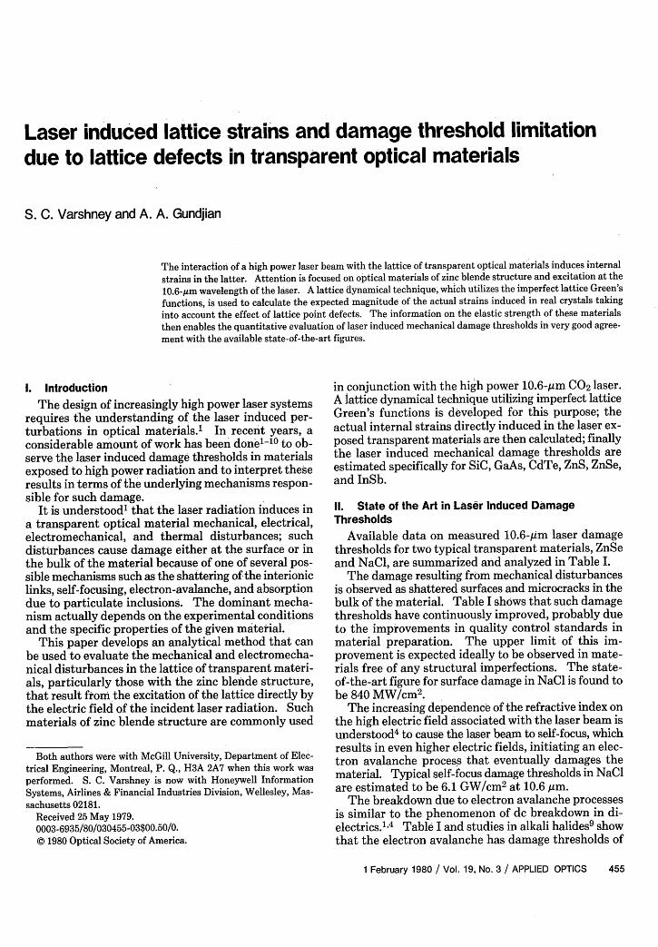
Laser induced lattice strains and damage threshold limitation due to lattice defects in transparent optical materials S. C. Varshney and A. A. Gundjian The interaction of a high power laser beam with the lattice of transparent optical materials induces internal strains in the latter. Attention is focused on optical materials of zinc blende structure and excitation at the 10.6-limwavelength of the laser. A lattice dynamical technique, which utilizes the imperfect lattice Green's functions, is used to calculate the expected magnitude of the actual strains induced in real crystals taking into account the effect of lattice point defects. The information on the elastic strength of these materials then enables the quantitative evaluation of laser induced mechanical damage thresholds in very good agree- ment with the available state-of-the-art figures. 1. Introduction The design of increasingly high power laser systems requires the understanding of the laser induced per- turbations in optical materials.' In recent years, a considerable amount of work has been done'l- 0 to ob- serve the laser induced damage thresholds in materials exposed to high power radiation and to interpret these results in terms of the underlying mechanisms respon- sible for such damage. It is understood' that the laser radiation induces in a transparent optical material mechanical, electrical, electromechanical, and thermal disturbances; such disturbances cause damage either at the surface or in the bulk of the material because of one of several pos- sible mechanisms such as the shattering of the interionic links, self-focusing, electron-avalanche, and absorption due to particulate inclusions. The dominant mecha- nism actually depends on the experimental conditions and the specific properties of the given material. This paper develops an analytical method that can be used to evaluate the mechanical and electromecha- nical disturbances in the lattice of transparent materi- als, particularly those with the zinc blende structure, that result from the excitation of the lattice directly by the electric field of the incident laser radiation. Such materials of zinc blende structure are commonly used Both authors were with McGill University, Department of Elec- trical Engineering, Montreal, P. Q., H3A 2A7 when this work was performed. S. C. Varshney is now with Honeywell Information Systems, Airlines & Financial Industries Division, Wellesley, Mas- sachusetts 02181. Received 25 May 1979. 0003-6935/80/030455-03$00.50/0. © 1980 Optical Society of America. in conjunction with the high power 10.6-,um CO 2 laser. A lattice dynamical technique utilizing imperfect lattice Green's functions is developed for this purpose; the actual internal strains directly induced in the laser ex- posed transparent materials are then calculated;finally the laser induced mechanical damage thresholds are estimated specifically for SiC, GaAs, CdTe, ZnS, ZnSe, and InSb. II. State of the Art in Laser Induced Damage Thresholds Available data on measured 10.6-/Im laser damage thresholds for two typical transparent materials, ZnSe and NaCl, are summarized and analyzed in Table I. The damage resulting from mechanical disturbances is observed as shattered surfaces and microcracks in the bulk of the material. Table I shows that such damage thresholds have continuously improved, probably due to the improvements in quality control standards in material preparation. The upper limit of this im- provement is expected ideally to be observed in mate- rials free of any structural imperfections. The state- of-the-art figure for surface damage in NaCl is found to be 840 MW/cm 2 . The increasing dependence of the refractive index on the high electric field associated with the laser beam is understood 4 to cause the laser beam to self-focus, which results in even higher electric fields, initiating an elec- tron avalanche process that eventually damages the material. Typical self-focus damage thresholds in NaCl are estimated to be 6.1 GW/cm 2 at 10.6 ttm. The breakdown due to electron avalanche processes is similar to the phenomenon of dc breakdown in di- electrics.", 4 Table I and studies in alkali halides 9 show that the electron avalanche has damage thresholds of 1 February 1980 / Vol. 19, No. 3 / APPLIEDOPTICS 455

Welcome message from author
This document is posted to help you gain knowledge. Please leave a comment to let me know what you think about it! Share it to your friends and learn new things together.
Transcript
Laser induced lattice strains and damage threshold limitationdue to lattice defects in transparent optical materials
S. C. Varshney and A. A. Gundjian
The interaction of a high power laser beam with the lattice of transparent optical materials induces internal
strains in the latter. Attention is focused on optical materials of zinc blende structure and excitation at the10.6-lim wavelength of the laser. A lattice dynamical technique, which utilizes the imperfect lattice Green'sfunctions, is used to calculate the expected magnitude of the actual strains induced in real crystals taking
into account the effect of lattice point defects. The information on the elastic strength of these materialsthen enables the quantitative evaluation of laser induced mechanical damage thresholds in very good agree-
ment with the available state-of-the-art figures.
1. Introduction
The design of increasingly high power laser systemsrequires the understanding of the laser induced per-turbations in optical materials.' In recent years, aconsiderable amount of work has been done'l- 0 to ob-serve the laser induced damage thresholds in materialsexposed to high power radiation and to interpret theseresults in terms of the underlying mechanisms respon-sible for such damage.
It is understood' that the laser radiation induces ina transparent optical material mechanical, electrical,electromechanical, and thermal disturbances; suchdisturbances cause damage either at the surface or inthe bulk of the material because of one of several pos-sible mechanisms such as the shattering of the interioniclinks, self-focusing, electron-avalanche, and absorptiondue to particulate inclusions. The dominant mecha-nism actually depends on the experimental conditionsand the specific properties of the given material.
This paper develops an analytical method that canbe used to evaluate the mechanical and electromecha-nical disturbances in the lattice of transparent materi-als, particularly those with the zinc blende structure,that result from the excitation of the lattice directly bythe electric field of the incident laser radiation. Suchmaterials of zinc blende structure are commonly used
Both authors were with McGill University, Department of Elec-trical Engineering, Montreal, P. Q., H3A 2A7 when this work wasperformed. S. C. Varshney is now with Honeywell InformationSystems, Airlines & Financial Industries Division, Wellesley, Mas-sachusetts 02181.
Received 25 May 1979.0003-6935/80/030455-03$00.50/0.© 1980 Optical Society of America.
in conjunction with the high power 10.6-,um CO2 laser.A lattice dynamical technique utilizing imperfect latticeGreen's functions is developed for this purpose; theactual internal strains directly induced in the laser ex-posed transparent materials are then calculated; finallythe laser induced mechanical damage thresholds areestimated specifically for SiC, GaAs, CdTe, ZnS, ZnSe,and InSb.
II. State of the Art in Laser Induced Damage
Thresholds
Available data on measured 10.6-/Im laser damagethresholds for two typical transparent materials, ZnSeand NaCl, are summarized and analyzed in Table I.
The damage resulting from mechanical disturbancesis observed as shattered surfaces and microcracks in thebulk of the material. Table I shows that such damagethresholds have continuously improved, probably dueto the improvements in quality control standards inmaterial preparation. The upper limit of this im-provement is expected ideally to be observed in mate-rials free of any structural imperfections. The state-of-the-art figure for surface damage in NaCl is found tobe 840 MW/cm 2 .
The increasing dependence of the refractive index onthe high electric field associated with the laser beam isunderstood 4 to cause the laser beam to self-focus, whichresults in even higher electric fields, initiating an elec-tron avalanche process that eventually damages thematerial. Typical self-focus damage thresholds in NaClare estimated to be 6.1 GW/cm2 at 10.6 ttm.
The breakdown due to electron avalanche processesis similar to the phenomenon of dc breakdown in di-electrics.", 4 Table I and studies in alkali halides9 showthat the electron avalanche has damage thresholds of
1 February 1980 / Vol. 19, No. 3 / APPLIED OPTICS 455
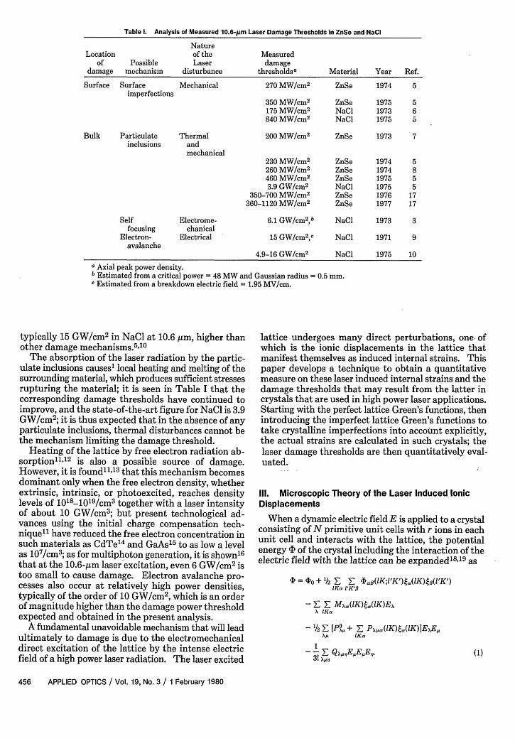
Table I. Analysis of Measured 10.6-Am Laser Damage Thresholds in ZnSe and NaCI
NatureLocation of the Measured
of Possible Laser damagedamage mechanism disturbance thresholdsa Material Year Ref.
Surface Surface Mechanical 270 MW/cm 2 ZnSe 1974 5imperfections
350 MW/cm 2 ZnSe 1975 5175 MW/cm 2 NaCl 1973 6840 MW/cm 2 NaCl 1975 5
Bulk Particulate Thermal 200 MW/cm 2 ZnSe 1973 7inclusions and
mechanical230 MW/cm 2 ZnSe 1974 5260 MW/cm 2 ZnSe 1974 8460 MW/cm 2 ZnSe 1975 53.9 GW/cm2 NaCl 1975 5
350-700 MW/cm 2 ZnSe 1976 17360-1120 MW/cm 2 ZnSe 1977 17
Self Electrome- 6.1 GW/cm2 ,b NaCl 1973 3focusing chanical
Electron- Electrical 15 GW/cm2 ,c NaCl 1971 9avalanche
4.9-16 GW/cm2 NaCl 1975 10
a Axial peak power density.b Estimated from a critical power = 48 MW and Gaussian radius = 0.5 mm.c Estimated from a breakdown electric field = 1.95 MV/cm.
typically 15 GW/cm2 in NaCl at 10.6 gim, higher thanother damage mechanisms.5"10
The absorption of the laser radiation by the partic-ulate inclusions causes' local heating and melting of thesurrounding material, which produces sufficient stressesrupturing the material; it is seen in Table I that thecorresponding damage thresholds have continued toimprove, and the state-of-the-art figure for NaCl is 3.9GW/cm2; it is thus expected that in the absence of anyparticulate inclusions, thermal disturbances cannot bethe mechanism limiting the damage threshold.
Heating of the lattice by free electron radiation ab-sorption1"1 2 is also a possible source of damage.However, it is found"",13 that this mechanism becomesdominant only when the free electron density, whetherextrinsic, intrinsic, or photoexcited, reaches densitylevels of 1018 -10' 9 /cm3 together with a laser intensityof about 10 GW/cm3; but present technological ad-vances using the initial charge compensation tech-nique" have reduced the free electron concentration insuch materials as CdTe14 and GaAs15 to as low a levelas 107 /cm3 ; as for multiphoton generation, it is shown'6
that at the 10.6-gtm laser excitation, even 6 GW/cm 2 istoo small to cause damage. Electron avalanche pro-cesses also occur at relatively high power densities,typically of the order of 10 GW/cm2, which is an orderof magnitude higher than the damage power thresholdexpected and obtained in the present analysis.
A fundamental unavoidable mechanism that will leadultimately to damage is due to the electromechanicaldirect excitation of the lattice by the intense electricfield of a high power laser radiation. The laser excited
lattice undergoes many direct perturbations, one ofwhich is the ionic displacements in the lattice thatmanifest themselves as induced internal strains. Thispaper develops a technique to obtain a quantitativemeasure on these laser induced internal strains and thedamage thresholds that may result from the latter incrystals that are used in high power laser applications.Starting with the perfect lattice Green's functions, thenintroducing the imperfect lattice Green's functions totake crystalline imperfections into account explicitly,the actual strains are calculated in such crystals; thelaser damage thresholds are then quantitatively eval-uated.
111. Microscopic Theory of the Laser Induced IonicDisplacements
When a dynamic electric field E is applied to a crystalconsisting of N primitive unit cells with r ions in eachunit cell and interacts with the lattice, the potentialenergy 'b of the crystal including the interaction of theelectric field with the lattice can be expanded' 8"19 as
= ,,o + 1/2 Z E 1a.(1K;'K')a(lK)tl(1'K')
F E M(lK)ta(1K)ExX 1K K'
A IKa
1/2 Z [PA,. + _ Px,.(1K)ta(1K)]ExE,XA. IKa
3! QxPiEEE,.3. A?
(1)
456 APPLIED OPTICS / Vol. 19, No. 3 / 1 February 1980
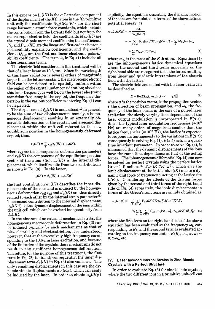
In this expansion ta(lK) is the a Cartesian componentof the displacement of the Kth atom in the th primitiveunit cell; the coefficients 4?a3(lK;1'K') are the shortrange harmonic atomic force constants, which includethe contribution from the Lorentz field but not from themacroscopic electric field; the coefficients MXa(1K) arethe crystal dipole moment coefficients; the coefficientsPo, and P\a(lK) are the linear and first-order electronicpolarizability expansion coefficients; and the coeffi-cients Q, are the first nonlinear electronic polariz-ability coefficients. The term 4 0 in Eq. (1) includes allother remaining terms.
The electric field considered in this treatment will bethat of a laser beam at 10.6 Am. Since the wavelengthof this laser radiation is several orders of magnitudelarger than the lattice constant, the macroscopic electricfield can be considered to be spatially uniform withinthe region of the crystal under consideration; also sincethis laser frequency is well below the lowest electronictransition frequency in the crystal, the frequency dis-persion in the various coefficients entering Eq. (1) canbe neglected.
The displacement ta(lK) is understood,'9 in general,to be the sum of two displacements, namely, a homo-geneous displacement resulting in an externally ob-servable deformation of the crystal, and a second dis-placement within the unit cell referred to the newequilibrium position in the homogeneously deformedcrystal; thus,
.a(WK) = £E Ea.X,(IK) + Va(lK), (2)
where em# are the homogeneous deformation parametersand xfl(lK) the components of the equilibrium positionvector of the atom (K); va (lK) is the internal dis-placement, which itself results from two contributionsas shown in Eq. (3). In the latter,
Va(lK) = da(lK) + ua(1K;t); (3)
the first contribution da,(lK) describes the inner dis-placements of the ions and is induced by the homoge-neous deformation E,6; Eats and dao(lK) are thus directlyrelated to each other by the internal strain parameter.20
The second contribution to the internal displacement,ua(lK;t), is the dynamic displacement of the ions withinthe unit cell, which can be excited independently fromda(lK).
In the absence of an external mechanical stress, thehomogeneous macroscopic deformation in Eq. (2) canbe induced typically by such mechanisms as that ofpiezoelectricity and electrostriction; it is understood,however, that at the excessively high frequency corre-sponding to the 10.6-gm laser excitation, and becauseof the finite size of the crystals, these mechanisms do notresult in any significant homogeneous deformation.Therefore, for the purpose of this treatment, the firstterm in Eq. (2) is absent; consequently, the inner dis-placement term d,,(K) in Eq. (3) also vanishes. Theonly remaining displacements in this case are the dy-namic atomic displacements ua(lK;t), which can easilybe induced by the laser. In order to obtain ua(lK;t)
explicitly, the equations describing the dynamic motionof the ions are formulated in terms of the above definedpotential energy, as
mKua(lK;t) =- a -
cua,(1K;t)
= - 4a#(1K;'K')u('K';t) + _ M\a(IK)EAIIK',B X
+ E PX,\a(lK)E,\E,,xj,
(4)
where mK is the mass of the Kth atom. Equations (4)are the inhomogeneous lattice dynamical equationswhere the second and third terms appearing on theright-hand side are recognized to be the forces resultingfrom linear and quadratic interactions of the electricfield with the lattice.
The electric field associated with the laser beam canbe described as
E = Re{E(x,t) exp[i(k r - WLt)]I (5)
where x is the position vector, k the propagation vector,r the direction of beam propagation, and WL the fre-quency of the laser beam; in the case of a pulsed laserexcitation, the slowly varying time dependence of thelaser output modulation is incorporated in E(x,t).Since the typical laser modulation frequencies (10 8
Hz) are many orders of magnitude smaller than thelattice frequencies (_1013 Hz), the lattice is expectedto respond instantaneously to the variations in E(x,t);consequently in solving Eq. (4), E(x,t) acts as a quasi-time invariant parameter. In order to solve Eq. (4), itis assumed that the dynamic displacements of the ionshave the same time dependence as that of the actingforces. The inhomogeneous differential Eq. (4) can nowbe solved for perfect crystals using the perfect latticeGreen's functions,2' r,(lK;'K';W 2), which give theionic displacement at the lattice site (1K) due to a dy-namic unit force of frequency c acting at the lattice site(1'K'). Considering the effects of the driving forcesgiven by the second and third terms of the right-handside of Eq. (4) separately, the ionic displacements interms of the Green's functions are simply obtained as
u.(lK;t) = Z ra.j(1K;1'K';w')Mxj3(l'K')ExL ~~~X INKED
- '/2 Xi E E Pap(1K;1'K;cl)Px(lK)Ex,' (6).1 XA INKED8
where the first term on the right-hand side of the aboveequation has been evaluated at the frequency WL cor-responding to EA, and the second term is evaluated ac-cording to the frequency content of EAE,1 , i.e., at w1 =0, 2CL, etc.
IV. Laser Induced Internal Strains in Zinc BlendeCrystals with a Perfect Structure
In order to evaluate Eq. (6) for zinc blende crystals,where the two different ions in a primitive unit cell can
1 February 1980 / Vol. 19, No. 3 APPLIED OPTICS 457
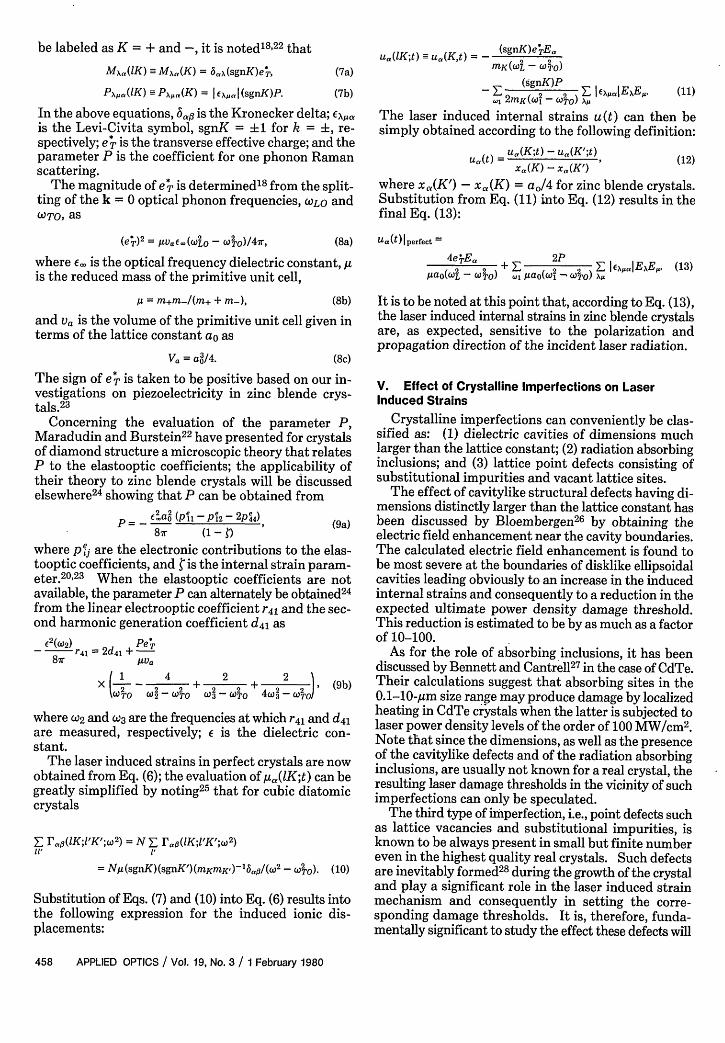
be labeled as K = + and -, it is noted'8' 22 that
Mxa(lK) --M\a(K) = 5.x(sgnK)e4, (7a)
P,\,a(1K) --Pa\,(K) = I ,\ I (sgnK)P. (7b)
In the above equations, 6,g is the Kronecker delta; EExis the Levi-Civita symbol, sgnK = ±1 for k = i, re-spectively; e p is the transverse effective charge; and theparameter P is the coefficient for one phonon Ramanscattering.
The magnitude of e p is determinedl8 from the split-ting of the k = 0 optical phonon frequencies, WLO andWTO as
(e*)2 = IVuae,(wUO - W 2o)/47r, (8a)
where E_ is the optical frequency dielectric constant, gis the reduced mass of the primitive unit cell,
,u = m+m-/(m+ + m-), (8b)
and va is the volume of the primitive unit cell given interms of the lattice constant ao as
Va = a/4.
ua(lK;t) u( Kt) = - (sgnK)e4Ea2K- 2 -MK (LCO) TO)
1 m(o2 (t F E,. I AaE xE. (11)., 2MKw -COTO) ,-
The laser induced internal strains u(t) can then besimply obtained according to the following definition:
Ua(t) = Ua (K;t) - u(K';t)Uax) X(K) - x. (K') (2
where xa(K') - X,(K) = ao/4 for zinc blende crystals.Substitution from Eq. (11) into Eq. (12) results in thefinal Eq. (13):
Ua(t)Iperfect =
4, e .EaO _+ F- 2P _ I )EXI aIExE0.tao(wa 2 _ W 2) ., kpa O(w0 _ ('.2) t
(13)
It is to be noted at this point that, according to Eq. (13),the laser induced internal strains in zinc blende crystalsare, as expected, sensitive to the polarization andpropagation direction of the incident laser radiation.
(8c)
The sign of e* is taken to be positive based on our in-vestigations on piezoelectricity in zinc blende crys-tals.2 3
Concerning the evaluation of the parameter P,Maradudin and Burstein2 2 have presented for crystalsof diamond structure a microscopic theory that relatesP to the elastooptic coefficients; the applicability oftheir theory to zinc blende crystals will be discussedelsewhere24 showing that P can be obtained from
aO (P11 -P2- 2P44)P ~~~~~~~~~~~(9a)87r (1-i
where pej are the electronic contributions to the elas-tooptic coefficients, and P is the internal strain param-eter.2023 When the elastooptic coefficients are notavailable, the parameter P can alternately be obtained24
from the linear electrooptic coefficient r 4l and the sec-ond harmonic generation coefficient d4 as
E62 (W2) PeTp
_ 12 41 =2d4l + e87r AVa
X + -~ + ~ ~ (9b)UO W2-2r WT 3 COTO 4w3 TI
where W2 and W3 are the frequencies at which r 4 l and d 4 lare measured, respectively; is the dielectric con-stant.
The laser induced strains in perfect crystals are nowobtained from Eq. (6); the evaluation of ,,(lK;t) can begreatly simplified by noting25 that for cubic diatomiccrystals
Z Fa,3(lK;1'K';W2) = N F- r(lK;'K';W 2 )
= NA(sgnK)(sgnK)(mKmK' lTO/(° - wTO). (10)
Substitution of Eqs. (7) and (10) into Eq. (6) results intothe following expression for the induced ionic dis-placements:
V. Effect of Crystalline Imperfections on LaserInduced Strains
Crystalline imperfections can conveniently be clas-sified as: (1) dielectric cavities of dimensions muchlarger than the lattice constant; (2) radiation absorbinginclusions; and (3) lattice point defects consisting ofsubstitutional impurities and vacant lattice sites.
The effect of cavitylike structural defects having di-mensions distinctly larger than the lattice constant hasbeen discussed by Bloembergen26 by obtaining theelectric field enhancement near the cavity boundaries.The calculated electric field enhancement is found tobe most severe at the boundaries of disklike ellipsoidalcavities leading obviously to an increase in the inducedinternal strains and consequently to a reduction in theexpected ultimate power density damage threshold.This reduction is estimated to be by as much as a factorof 10-100.
As for the role of absorbing inclusions, it has beendiscussed by Bennett and Cantrell2 7 in the case of CdTe.Their calculations suggest that absorbing sites in the0.1-10-,m size range may produce damage by localizedheating in CdTe crystals when the latter is subjected tolaser power density levels of the order of 100 MW/cm2.Note that since the dimensions, as well as the presenceof the cavitylike defects and of the radiation absorbinginclusions, are usually not known for a real crystal, theresulting laser damage thresholds in the vicinity of suchimperfections can only be speculated.
The third type of imperfection, i.e., point defects suchas lattice vacancies and substitutional impurities, isknown to be always present in small but finite numbereven in the highest quality real crystals. Such defectsare inevitably formed28 during the growth of the crystaland play a significant role in the laser induced strainmechanism and consequently in setting the corre-sponding damage thresholds. It is, therefore, funda-mentally significant to study the effect these defects will
458 APPLIED OPTICS / Vol. 19, No. 3 / 1 February 1980
(12)
have on the interaction of a high power laser beam,specifically in the case of IR optical materials.
In this paper, we evaluate the effect of lattice pointdefects on the actual strains induced in zinc blendematerials exposed to 10.6-gm CO2 laser radiation.
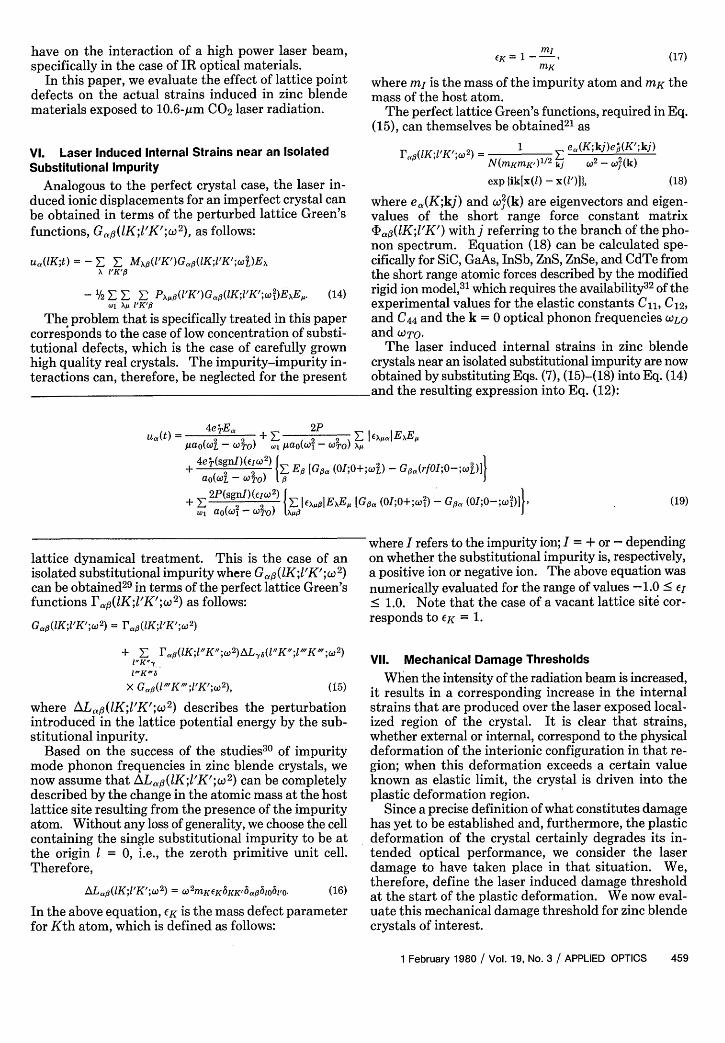
VI. Laser Induced Internal Strains near an IsolatedSubstitutional Impurity
Analogous to the perfect crystal case, the laser in-duced ionic displacements for an imperfect crystal canbe obtained in terms of the perturbed lattice Green'sfunctions, Ga,',3 (K;'K';w 2), as follows:
ua(lK;t) =-E E Mx(I'K')Gi(IK;'K' ;CL)ExX 'K'ft
-1/2E E 2 PxJ(1'K')Gaj3(lK;1'K';.,i)E\E,. (14).1 X 'K'fl
The problem that is specifically treated in this papercorresponds to the case of low concentration of substi-tutional defects, which is the case of carefully grownhigh quality real crystals. The impurity-impurity in-teractions can, therefore, be neglected for the present
EK = -MK
(17)
where mj is the mass of the impurity atom and mK themass of the host atom.
The perfect lattice Green's functions, required in Eq.(15), can themselves be obtained 2 l as
r(1'K;1K; 2) =- 1 ea(K;kj)e:(K';kj)N(inKraK')112 kj W2-2(k)
exp ik[x(l) - x(l')], (18)
where ea,(K;kj) and 0(k) are eigenvectors and eigen-values of the short range force constant matrix4afl(IK;l'K') with j referring to the branch of the pho-non spectrum. Equation (18) can be calculated spe-cifically for SiC, GaAs, InSb, ZnS, ZnSe, and CdTe fromthe short range atomic forces described by the modifiedrigid ion model,3 ' which requires the availability3 2 of theexperimental values for the elastic constants C11, C12,and C44 and the k = 0 optical phonon frequencies CO)LO
and OTO.The laser induced internal strains in zinc blende
crystals near an isolated substitutional impurity are nowobtained by substituting Eqs. (7), (15)-(18) into Eq. (14)
-and the resulting expression into Eq. (12):
U(t) 4eErEa + , 2P 2 E LaIEXEt2- 2o pa(w02 - Co)paO(wL-W TO) .14a1 aOo-TO) X/1
2eP(sgnI) (EI2
)
+ 02 j 0x, I0ExE, [G (GI;O+;c0rOI-;G (I;O-;W a -TO) ,3
lattice dynamical treatment. This is the case of anisolated substitutional impurity where Gaf(IK;1'K';c2)can be obtained 2 9 in terms of the perfect lattice Green'sfunctions rPaj(lK;l'K';C02 ) as follows:
Ga,3(lK;1'K';W2 ) = ra,(lK;1'K';W2)
+ _ ra,((lK;1"K";&;2 )eXL(l"K";l"'K';W 2 )
x G,1("'K';1'K';2), (15)
where ALa(1K;1'K'; 2) describes the perturbationintroduced in the lattice potential energy by the sub-stitutional inpurity.
Based on the success of the studies 3 0 of impuritymode phonon frequencies in zinc blende crystals, wenow assume that AL, 3,(lK;1'K';w 2) can be completelydescribed by the change in the atomic mass at the hostlattice site resulting from the presence of the impurityatom. Without any loss of generality, we choose the cellcontaining the single substitutional impurity to be atthe origin 1 = 0, i.e., the zeroth primitive unit cell.Therefore,
ALa,3(1K;l'K';w 2 ) = W2 MKEK6KK'ba,361061'0 (16)
In the above equation, EK is the mass defect parameterfor Kth atom, which is defined as follows:
where I refers to the impurity ion; I = + or - dependingon whether the substitutional impurity is, respectively,a positive ion or negative ion. The above equation wasnumerically evaluated for the range of values -1.0 S El< 1.0. Note that the case of a vacant lattice site cor-responds to EK = 1.
VII. Mechanical Damage Thresholds
When the intensity of the radiation beam is increased,it results in a corresponding increase in the internalstrains that are produced over the laser exposed local-ized region of the crystal. It is clear that strains,whether external or internal, correspond to the physicaldeformation of the interionic configuration in that re-gion; when this deformation exceeds a certain valueknown as elastic limit, the crystal is driven into theplastic deformation region.
Since a precise definition of what constitutes damagehas yet to be established and, furthermore, the plasticdeformation of the crystal certainly degrades its in-tended optical performance, we consider the laserdamage to have taken place in that situation. We,therefore, define the laser induced damage thresholdat the start of the plastic deformation. We now eval-uate this mechanical damage threshold for zinc blendecrystals of interest.
1 February 1980 / Vol. 19, No. 3 / APPLIED OPTICS 459
(19)
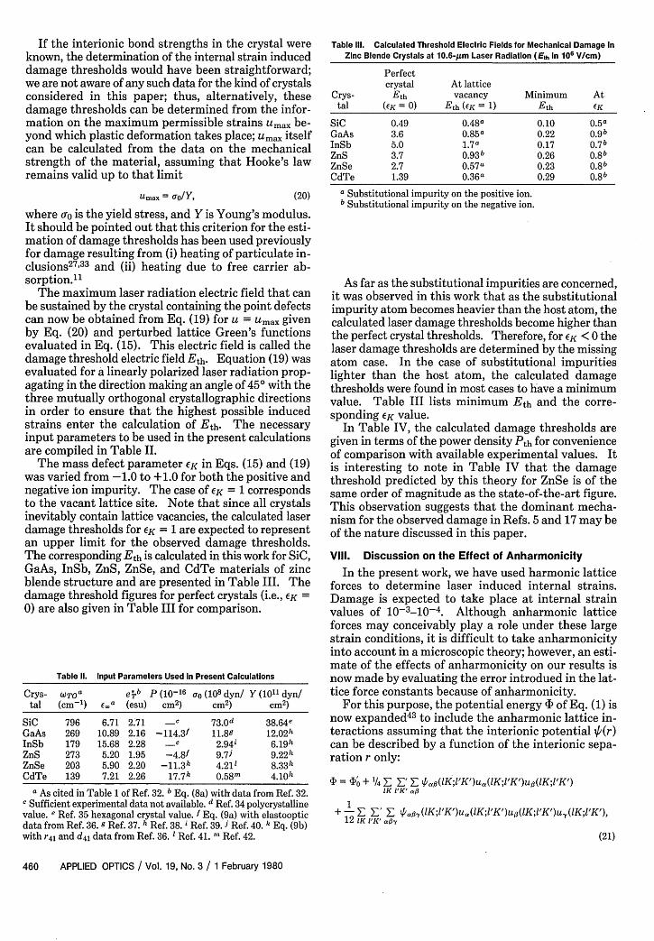
If the interionic bond strengths in the crystal vknown, the determination of the internal strain indudamage thresholds would have been straightforwtwe are not aware of any such data for the kind of crysconsidered in this paper; thus, alternatively, tldamage thresholds can be determined from the inmation on the maximum permissible strains Umaxyond which plastic deformation takes place; Umax itcan be calculated from the data on the mechanstrength of the material, assuming that Hooke'sremains valid up to that limit
Umax =ao/y,
where Io is the yield stress, and Y is Young's moduIt should be pointed out that this criterion for the emation of damage thresholds has been used previoifor damage resulting from (i) heating of particulateclusions27 ,33 and (ii) heating due to free carriersorption."
The maximum laser radiation electric field thatbe sustained by the crystal containing the point defcan now be obtained from Eq. (19) for u = Umax giby Eq. (20) and perturbed lattice Green's functievaluated in Eq. (15). This electric field is calleddamage threshold electric field Eth. Equation (19)evaluated for a linearly polarized laser radiation piagating in the direction making an angle of 45° withthree mutually orthogonal crystallographic directiin order to ensure that the highest possible industrains enter the calculation of Eth. The necessinput parameters to be used in the present calculatiare compiled in Table II.
The mass defect parameter EK in Eqs. (15) andwas varied from -1.0 to +1.0 for both the positivenegative ion impurity. The case of EK = 1 correspoto the vacant lattice site. Note that since all crysinevitably contain lattice vacancies, the calculated edamage thresholds for EK = 1 are expected to represan upper limit for the observed damage threshoThe corresponding Eth is calculated in this work for 'GaAs, InSb, ZnS, ZnSe, and CdTe materials of blende structure and are presented in Table III. 'damage threshold figures for perfect crystals (i.e., ,0) are also given in Table III for comparison.
Table II. Input Parameters Used in Present Calculations
Crys- WTOa eib P (10-16 a (108 dyn/ Y (1011 dyn/tal (cm 1 ) ECa (esu) cm2 ) cm2 ) cm2 )
SiC 796 6.71 2.71 -c 73.0d 38.64eGaAs 269 10.89 2.16 -114.3f 11.89 12.02hInSb 179 15.68 2.28 -c 2.94i 6.19hZnS 273 5.20 1.95 -4.8f 9.7J 9 .2 2 hZnSe 203 5.90 2.20 - 1 1 .3k 4.211 8.33hCdTe 139 7.21 2.26 17 . 7 k 0.58m 4 .10 h
a As cited in Table 1 of Ref. 32. b Eq. (8a) with data from Ref. 32.c Sufficient experimental data not available. d Ref. 34 polycrystallinevalue. e Ref. 35 hexagonal crystal value. f Eq. (9a) with elastoopticdata from Ref. 36. g Ref. 37. h Ref. 38. Ref. 39. Ref. 40. k Eq. (9b)with r4 l and d4 l data from Ref. 36.1 Ref. 41. m Ref. 42.
iere Table IlIl. Calculated Threshold Electric Fields for Mechanical Damage Iniced Zinc Blende Crystals at 10.6-Am Laser Radiation (Eth In 106 V/cm)
ard; Perfecttals crystal At latticeiese Crys- Eth vacancy Minimum Atfor- tal (EK = 0) Eth (K = 1) Eth eKbe- SiC 0.49 0.48a 0.10 0.5aself GaAs 3.6 0.85a 0.22 0.9bical InSb 5.0 1.7a 0.17 0.7b
ZnS 3.7 0.93b 0.26 0 .8blaw ZnSe 2.7 0.57a 0.23 0 .8 b
CdTe 1.39 0.36a 0.29 0 .8 b
(20) a Substitutional impurity on the positive ion.b Substitutional impurity on the negative ion.
As far as the substitutional impurities are concerned,it was observed in this work that as the substitutionalimpurity atom becomes heavier than the host atom, thecalculated laser damage thresholds become higher thanthe perfect crystal thresholds. Therefore, for EK < 0 thelaser damage thresholds are determined by the missingatom case. In the case of substitutional impuritieslighter than the host atom, the calculated damagethresholds were found in most cases to have a minimumvalue. Table III lists minimum Eth and the corre-sponding EK value.
In Table IV, the calculated damage thresholds aregiven in terms of the power density Pth for convenienceof comparison with available experimental values. Itis interesting to note in Table IV that the damagethreshold predicted by this theory for ZnSe is of thesame order of magnitude as the state-of-the-art figure.This observation suggests that the dominant mecha-nism for the observed damage in Refs. 5 and 17 may beof the nature discussed in this paper.
Vil. Discussion on the Effect of Anharmonicity
In the present work, we have used harmonic latticeforces to determine laser induced internal strains.Damage is expected to take place at internal strainvalues of 10-3-10-4. Although anharmonic latticeforces may conceivably play a role under these largestrain conditions, it is difficult to take anharmonicityinto account in a microscopic theory; however, an esti-mate of the effects of anharmonicity on our results isnow made by evaluating the error introdued in the lat-tice force constants because of anharmonicity.
For this purpose, the potential energy 4 of Eq. (1) isnow expanded43 to include the anharmonic lattice in-teractions assuming that the interionic potential +(r)can be described by a function of the interionic sepa-ration r only:
= O0 + 1/4 E; a'/ Z a,(lK;I'K')ua(IK;1'K')ui(IK;1'K')1K IUK' a
1+-E L_' E '/oy(lK;1'K')ua(lK;'K')u(lK;1'K')u,(lK;1'K'),
12 1K I'K'. ay
(21)
460 APPLIED OPTICS / Vol. 19, No. 3 / 1 February 1980
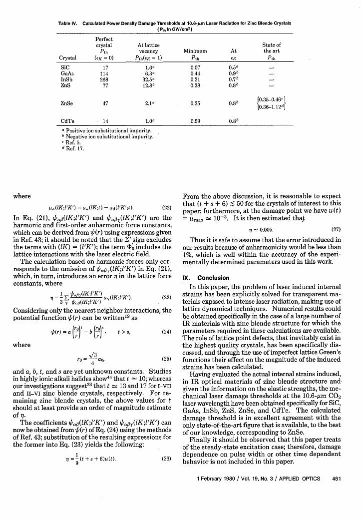
Table IV. Calculated Power Density Damage Thresholds at 10.6-pm Laser Radiation for Zinc Blende Crystals(Pth in GW/cm2)
Perfectcrystal At lattice State of
Pth vacancy Minimum At the artCrystal ((K = 0) Pth(EK = 1) Pth CK Pth
SiC 17 1.6" 0.07 0.5a -GaAs 114 6.3" 0.44 0.9b -InSb 268 32.5a 0.31 0.7 b -ZnS 77 1 2 .8 b 0.38 0.8b -
ZnSe 47 2.1a 0.35 0.8b J0.35-0.46c1110.36-1.1 2 d
CdTe 14 1.0a 0.59 0 .8 b
a Positive ion substitutional impurity.a Negative ion substitutional impurity.c Ref. 5.d Ref. 17.
where
u,,(lK;1'K') = u,(lK;t) - up(1'K';t). (22)
In Eq. (21), II#(lK;l'K') and q/,a,3(lK;'K') are theharmonic and first-order anharmonic force constants,which can be derived from lp(r) using expressions givenin Ref. 43; it should be noted that the I' sign excludesthe terms with (K) = (1'K'); the term 4'0 includes thelattice interactions with the laser electric field.
The calculation based on harmonic forces only cor-responds to the omission of VII'a(lK;1'K') in Eq. (21),which, in turn, introduces an error X in the lattice forceconstants, where
=3 E 4(lKl/K/) 1'K' (23)
Considering only the nearest neighbor interactions, thepotential function (r) can be written 19 as
i(r) = a ,-' -b °) s, t > s, (24)
where
'/3ro \-3 ao, (25)
and a, b, t, and s are yet unknown constants. Studiesin highly ionic alkali halides show44 that t 10; whereasour investigations suggest23 that t 13 and 17 for I-VII
and II-vi zinc blende crystals, respectively. For re-maining zinc blende crystals, the above values for tshould at least provide an order of magnitude estimateof q.
The coefficients la,(lK;l'K') and /,,.(lK;1'K') cannow be obtained from 4'(r) of Eq. (24) using the methodsof Ref. 43; substitution of the resulting expressions forthe former into Eq. (23) yields the following:
79 (t + s + 6)u(t). (26)
From the above discussion, it is reasonable to expectthat (t + s + 6) S 50 for the crystals of interest to thispaper; furthermore, at the damage point we have u(t)= Umax 10-3. It is then estimated th4
i 0.005. (27)
Thus it is safe to assume that the error introduced inour results because of anharmonicity would be less than1%, which is well within the accuracy of the experi-mentally determined parameters used in this work.
IX. Conclusion
In this paper, the problem of laser induced internalstrains has been explicitly solved for transparent ma-terials expssed to intense laser radiation, making use oflattice dynamical techniques. Numerical results couldbe obtained specifically in the case of a large number ofIR materials with zinc blende structure for which theparameters required in these calculations are available.The role of lattice point defects, that inevitably exist inthe highest quality crystals, has been specifically dis-cussed, and through the use of imperfect lattice Green'sfunctions their effect on the magnitude of the inducedstrains has been calculated.
Having evaluated the actual internal strains induced,in IR optical materials of zinc blende structure andgiven the information on the elastic strengths, the me-chanical laser damage thresholds at the 10.6-gm CO2laser wavelength have been obtained specifically for SiC,GaAs, InSb, ZnS, ZnSe, and CdTe. The calculateddamage threshold is in excellent agreement with theonly state-of-the-art figure that is available, to the bestof our knowledge, corresponding to ZnSe.
Finally it should be observed that this paper treatsof the steady-state excitation case; therefore, damagedependence on pulse width or other time dependentbehavior is not included in this paper.
1 February 1980 / Vol. 19, No. 3 / APPLIED OPTICS 461
The financial support by the National ResearchCouncil of Canada and the Quebec Department of Ed-ucation for the conduct of this work is gratefully ac-knowledged.
References1. A. J. Glass and A. H. Guenther, Appl. Opt. 12, 637 (1973); 13,74
(1974); 14, 698 (1975); 15, 1510 (1976).2. D. C. Hanna, B. Luther-Davies, H. N. Rutt, R. C. Smith, and C.
R. Stanley, IEEE J. Quantum Electron. QE-8, 317 (1972).3. D. W. Fradin, E. Yablonovitch, and M. Bass, Appl. Opt. 12, 700
(1973).4. A. K. Ghosh, RCA Rev. 35, 279 (1974).5. K. M. Leung, M. Bass, and A. G. J. Balbin-Villaverde, in Laser
Induced Damage in Optical Materials: 1975, A. J. Glass and A.H. Guenther, Eds. NBS Spec. Publ. 435 (U.S. GPO, Washington,D.C., 1975), pp. 107-117.
6. J. Davit, in Laser Induced Damage In Optical Materials: 1973,A. J. Glass and A. H. Guenther, Eds. NBS Spec. Publ. 387 (U.S.GPO, Washington, D.C., 1973), pp. 170-174.
7. A. J. Braunstein, V. Wang, M. Braunstein, J. E. Rudisill, and J.Wada, in Ref. 6, pp. 151-156.
8. D. W. Fradin and D.P. Bua, Appl. Phys. Lett. 24, 555 (1974).9. E. Yablonovitch, Appl. Phys. Lett. 19,495 (1971).
10. V. Wang, C. R. Giuliano, S. D. Allen, and R. C. Pastor, in Ref. 5,pp. 118-125.
11. R. W. Hellwarth, in Damage in Laser Materials: 1970, A. J. Glassand A. H. Guenther, Eds. NBS Spec. Publ. 341 (U.S. GPO,Washington, D.C., 1970), pp. 67-75.
12. R. W. Hellwarth, in Laser Induced Damage in Optical Materials:1972, A. J. Glass and A. H. Guenther, Eds. NBS Spec. Publ. 372(U.S. GPO, Washington, D.C., 1972), pp. 165-171.
13. N. Bloembergen, IEEE J. Quantum Electron. QE-10, 375(1974).
14. T. J. Magee, J. Peng, and J. Bean, Phys. Status Solidi A: 27,557(1975).
15. M. J. Brau and H. C. Hafner, in Proceedings, IEEE 1976 NationalAerospace and Electronics Conference, Dayton, Ohio, 18-20 May1976 (IEEE, New York, 1976), p. 357.
16. R. P. Benedict and A. H. Guenther, in Ref. 5, pp. 389-394.17. S. Sharma, R. M. Wood, and R. C. C. Ward, in Laser Induced
Damage in Optical Materials: 1977, A. J. Glass and A. H.Guenther, Eds. NBS Spec. Publ. 509, U.S. GPO, Washington,D.C., 1978), pp. 183-195.
18. A. A. Maradudin, E. W. Montroll, G. H. Weiss, and I. P. Ipatova,"Theory of Lattice Dynamics in Harmonic Approximation," inSolid State Physics, Suppl. 3 (Academic, New York, 1971), pp.244-256.
19. L. B. Humphreys and A. A. Maradudin, Phys. Rev. B: 6, 3868(1972).
20, L. Kleinman, Phys. Rev. 128, 2614 (1962); A. Segmfiller and H.R. Neyer, Phys. Kondens. Mater. 4, 63 (1965).
21. Ref. 18, pp. 65-66.22. A. A. Maradudin and E. Burstein, Phys. Rev. 164, 1081 (1967).23. S. C. Varshney and A. A. Gundjian, Phys. Status Solidi B: 85,
733 (1978).24. S. C. Varshney and A. A. Gundjian, to be published.25. This follows from Eqs. (2.3.4), (2.4.4.44a), and (6.5.47) of Ref.
18.26. N. Bloembergen, Appl. Opt. 12, 661 (1973).27. H. S. Bennett and C. D. Cantrell, J. Appl. Phys. 48, 522 (1977);
also Appl. Opt. 16, 2931 (1977).28. I. Kovdes and L. Zsoldos, Dislocations and Plastic Deformation
(Pergamon, New York, 1973), Chap. 3.29. Ref. 18, Chap. 8.30. S. P. Gaur, J. F. Vetelino, and S. S. Mitra, J. Phys. Chem. Solids
32, 2737 (1971).31. J. F. Vetelino and S. S. Mitra, Phys. Rev. 178, 1349 (1969).32. K. Kunc, M. Balkanski, and M. A. Nusimovici, Phys. Status Solidi
B: 72, 229 (1975).33. H. S. Bennett, J. Appl. Phys. 42, 619 (1971).34. T. D. Gulden, J. Am. Ceram. Soc. 52, 585 (1969).35. M. Neuberger, in Handbook of Electronic Materials, Vol. 5
(IFI/Plenum, New York, 1971), p. 48.36. R. J. Pressley, Ed., CRC Handbook of Lasers with Selected Data
on Optical Technology (Chemical Rubber Co., Cleveland,1971).
37. V. Swaminathan and S. M. Copley, J. Am. Ceram. Soc. 58, 482(1975).
38. G. Simmons and H. Wang, Single Crystal Elastic Constants andCalculated Aggregate Properties: A Handbook (MIT Press,Cambridge, Mass., 1971).
39. H. Shimizu and K. Sumio, Philos. Mag. 32, 123 (1975).40. Condensed Data from Kodak Irtran Infrared Optical Materials,
Kodak Pamphlet U-71 (Eastman Kodak, New York, 1971).41. J. C. Wurst, "Thermal, Electrical, and Physical Property Mea-
surements of Laser Window Materials," Tech. Report UDRI-QPR-73-19 (Nov. 1973).
42. R. I. Rudko and F. A. Horrigan, "Materials for High Power CO2Lasers," Raytheon Research Division Final Technical Report oncontract DAAH 01-69-C-0038, AD-693311 (1969).
43. A. A. Maradudin, in Dynamical Properties of Solids, Vol. 1, G.K. Horton and A. A. Maradudin, Eds. (North-Holland, New York,1974), Chap. 1.
44. See, for example, G. Busch and H. Schade, Lectures on SolidState Physics (Pergamon, New York, 1976), pp. 45-52.
462 APPLIED OPTICS / Vol. 19, No. 3 / 1 February 1980
Related Documents