SaleCNC.com carving cutter user’s manual 1 GuangZhou City,China E-mail:[email protected] LASER CONTROL PANNEL By:

Welcome message from author
This document is posted to help you gain knowledge. Please leave a comment to let me know what you think about it! Share it to your friends and learn new things together.
Transcript
SaleCNC.com carving cutter user’s manual
1
GuangZhou City,ChinaE-mail:[email protected]
LASER CONTROL PANNEL
By:
SaleCNC.com carving cutter user’s manual
2
GuangZhou City,ChinaE-mail:[email protected]
Table of Contents
1.Press keys……………………………………………………………………….1
2.Panel operation………………………………..………………………………...3
3.Trouble and troubleshooting …………………..………………………..…….24
4. CorelDraw Direct Output………………………………………………………26
5. AutoCAD Direct Output………………………………………………………..49
6.Buttons of the Carving/ Cutting Electronic Control System………………...71
7.Installation of the software dongle…………………………………………….72
8.Installing and debugging engraving system………………………………….74
9. Maintenance and maintenance………………………………………………78
10. Equipment frequently asked questions faq and solution…………………80
SaleCNC.com carving cutter user’s manual
3
GuangZhou City,ChinaE-mail:[email protected]
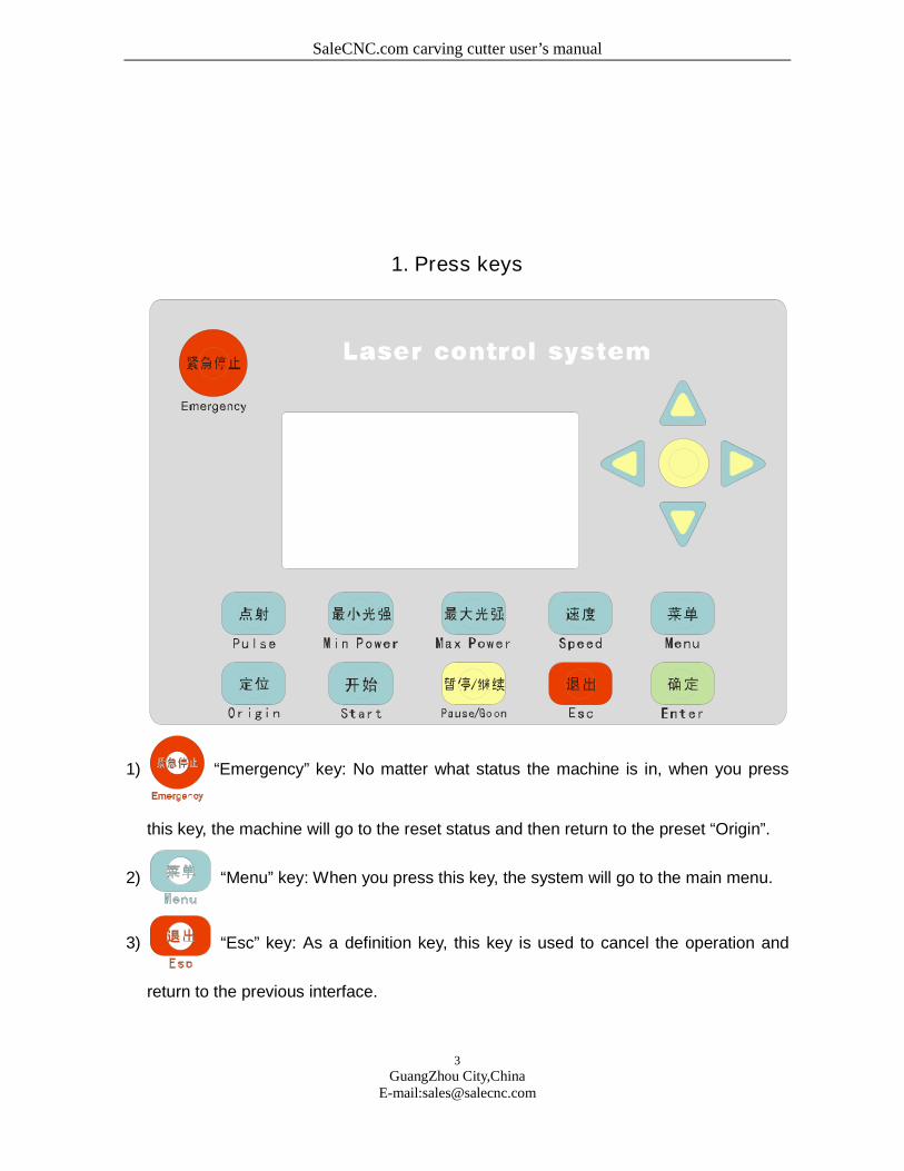
1. Press keys
1) “Emergency” key: No matter what status the machine is in, when you press
this key, the machine will go to the reset status and then return to the preset “Origin”.
2) “Menu” key: When you press this key, the system will go to the main menu.
3) “Esc” key: As a definition key, this key is used to cancel the operation and
return to the previous interface.
SaleCNC.com carving cutter user’s manual
4
GuangZhou City,ChinaE-mail:[email protected]
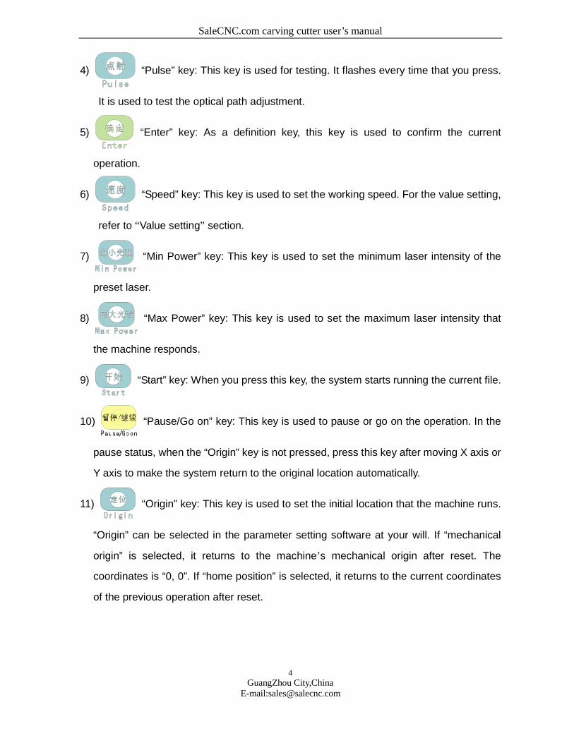
4) “Pulse” key: This key is used for testing. It flashes every time that you press.
It is used to test the optical path adjustment.
5) “Enter” key: As a definition key, this key is used to confirm the current
operation.
6) “Speed” key: This key is used to set the working speed. For the value setting,
refer to “Value setting” section.
7) “Min Power” key: This key is used to set the minimum laser intensity of the
preset laser.
8) “Max Power” key: This key is used to set the maximum laser intensity that
the machine responds.
9) “Start” key: When you press this key, the system starts running the current file.
10) “Pause/Go on” key: This key is used to pause or go on the operation. In the
pause status, when the “Origin” key is not pressed, press this key after moving X axis or
Y axis to make the system return to the original location automatically.
11) “Origin” key: This key is used to set the initial location that the machine runs.
“Origin” can be selected in the parameter setting software at your will. If “mechanical
origin” is selected, it returns to the machine’s mechanical origin after reset. The
coordinates is “0, 0”. If “home position” is selected, it returns to the current coordinates
of the previous operation after reset.
SaleCNC.com carving cutter user’s manual
5
GuangZhou City,ChinaE-mail:[email protected]
12) “ ”Up “ ”Down“ ”Left“ ”Right keys: In the waiting
status, they mean upward, downward, leftward and rightward movement.
2. Panel operation
Start up
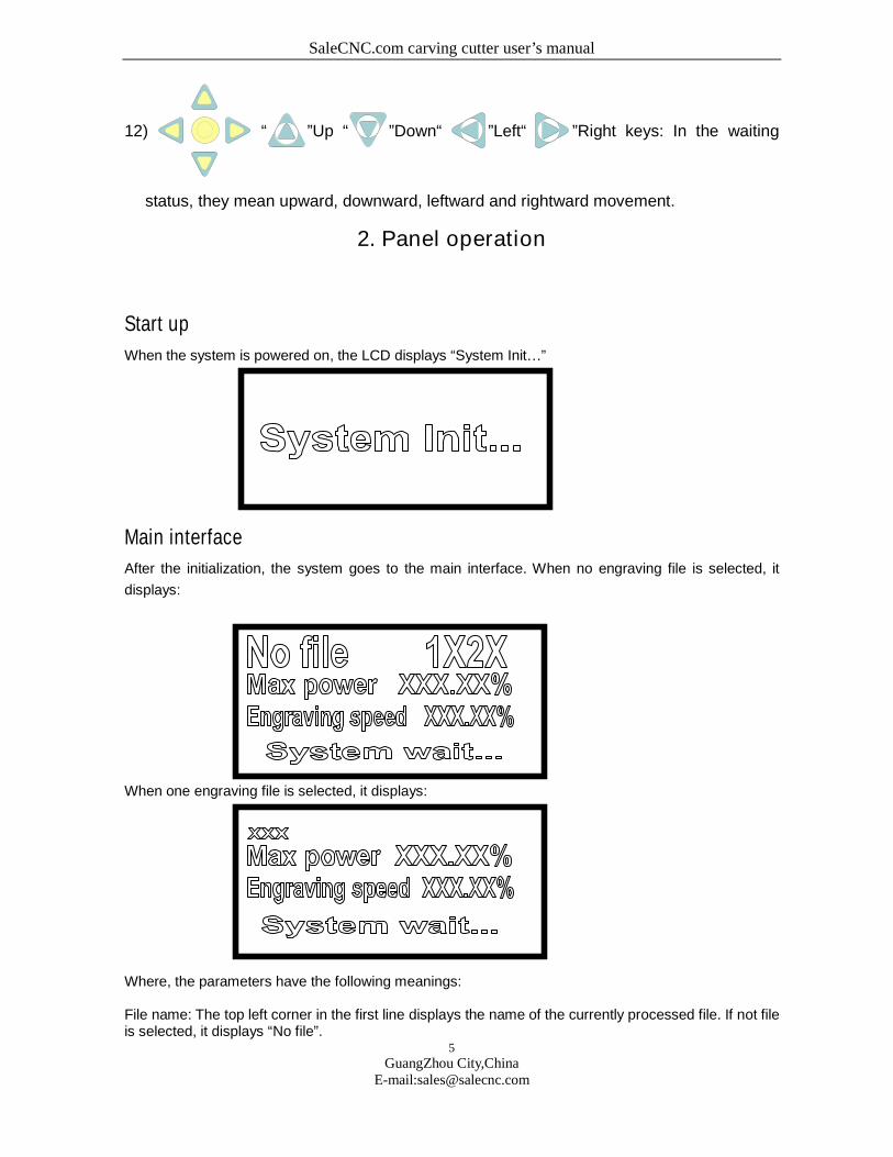
When the system is powered on, the LCD displays “System Init…”
Main interface
After the initialization, the system goes to the main interface. When no engraving file is selected, it
displays:
When one engraving file is selected, it displays:
Where, the parameters have the following meanings:
File name: The top left corner in the first line displays the name of the currently processed file. If not fileis selected, it displays “No file”.
SaleCNC.com carving cutter user’s manual
6
GuangZhou City,ChinaE-mail:[email protected]
Water protection prompt: The top right corner in the first line displays the water protection 1 and waterprotection 2 unconnected. If the water protection is enabled, it is not displayed.Max power: It allows setting the percentage of the maximum intensity in the processing file, anddisplays the intensity of laser 1.Engraving speed: It allows setting the percentage of engraving speed in the processing file.
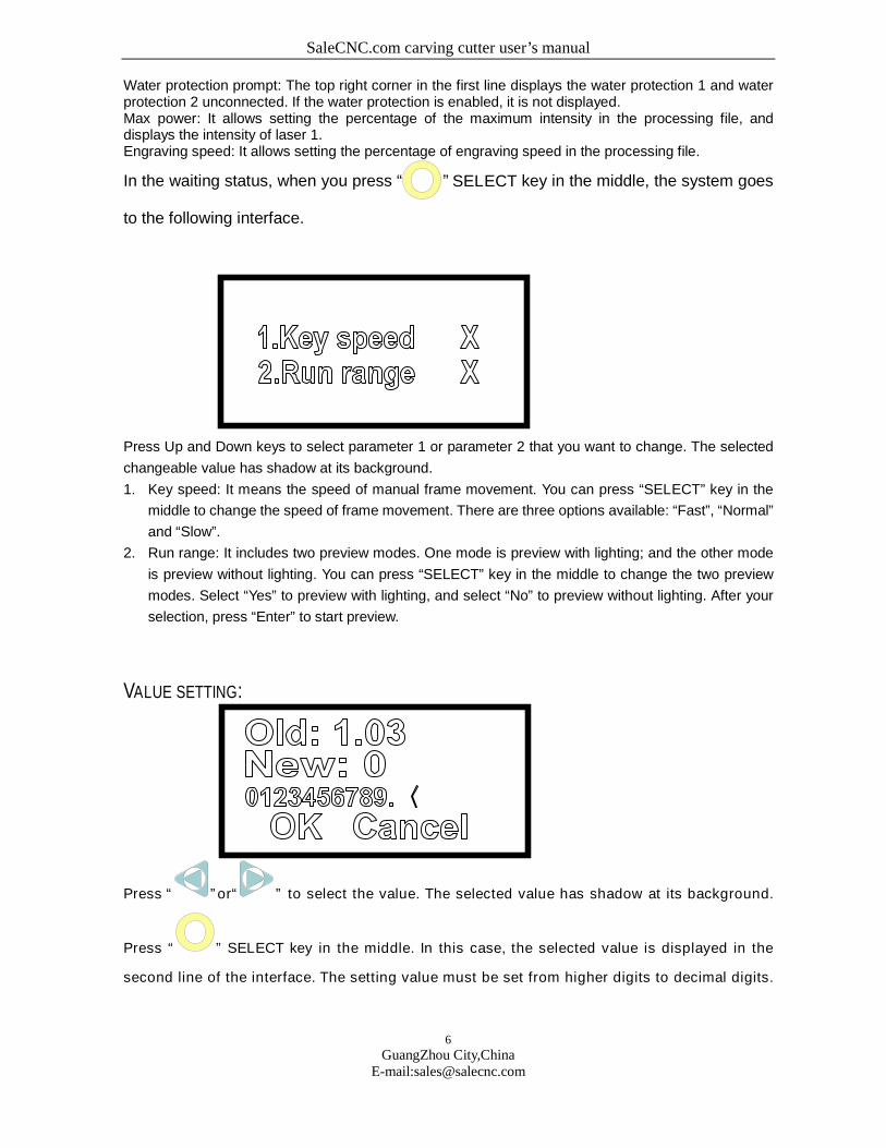
In the waiting status, when you press “ ” SELECT key in the middle, the system goes
to the following interface.
Press Up and Down keys to select parameter 1 or parameter 2 that you want to change. The selected
changeable value has shadow at its background.
1. Key speed: It means the speed of manual frame movement. You can press “SELECT” key in the
middle to change the speed of frame movement. There are three options available: “Fast”, “Normal”
and “Slow”.
2. Run range: It includes two preview modes. One mode is preview with lighting; and the other mode
is preview without lighting. You can press “SELECT” key in the middle to change the two preview
modes. Select “Yes” to preview with lighting, and select “No” to preview without lighting. After your
selection, press “Enter” to start preview.
VALUE SETTING:
Press “ ”or“ ” to select the value. The selected value has shadow at its background.
Press “ ” SELECT key in the middle. In this case, the selected value is displayed in the
second line of the interface. The setting value must be set from higher digits to decimal digits.

SaleCNC.com carving cutter user’s manual
7
GuangZhou City,ChinaE-mail:[email protected]
For example, if the setting value is 5.3, first press “ ”or“ ” to select ‘5‘; and then press “ ”
key to select ‘.‘; afterwards press “ ” key, to select ’3‘, finally press “ ” key. If you selected
“<”, press “ ” SELECT key in the middle to delete the currently set value. After your setting,
press “ ” to exit the setting interface. If you want to cancel this setting, you can directly
press “ ” to exit the setting interface.
Main menu interface
Press “Menu” key to go to main menu interface:
In this status, press “Min Power” key four times, and then press “MaxPower” keyfour times. Enter the management password, and press “SELECT” key to selectwhether enable the factory setting. If you enable the factory setting, you can directlymodify the factory setting on the panel. If you disable the factory setting, thecorresponding factory setting on the panel menu will not appear.Press “Up” and “Down” keys to move the cursor, and then press “Enter” to go to the sub-menu;
Sub-menu interface 1-file manage
01. Files
SaleCNC.com carving cutter user’s manual
8
GuangZhou City,ChinaE-mail:[email protected]
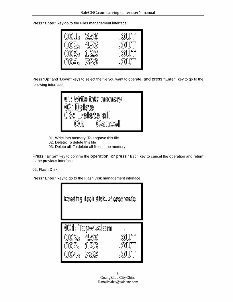
Press “Enter” key go to the Files management interface.
Press “Up” and “Down” keys to select the file you want to operate, and press “Enter” key to go to the
following interface.
01. Write into memory: To engrave this file02. Delete: To delete this file03. Delete all: To delete all files in the memory
Press “Enter” key to confirm the operation, or press “Esc” key to cancel the operation and returnto the previous interface.
02. Flash Disk
Press “Enter” key to go to the Flash Disk management interface:
SaleCNC.com carving cutter user’s manual
9
GuangZhou City,ChinaE-mail:[email protected]
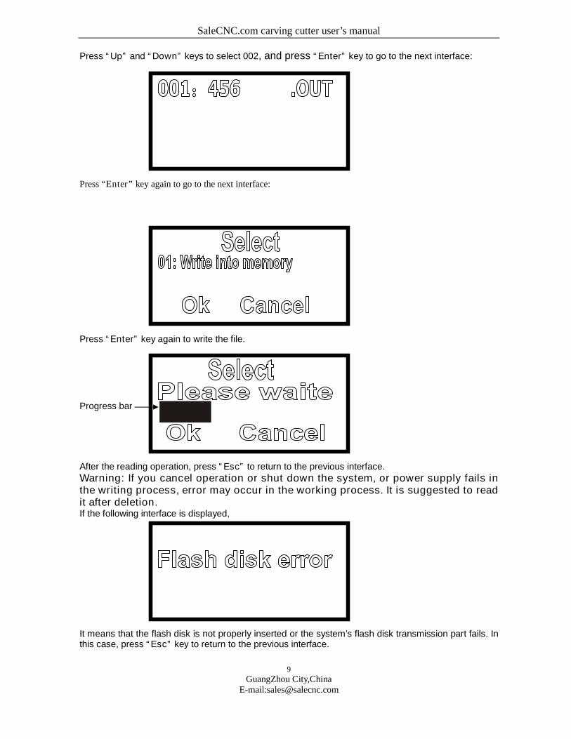
Press “Up” and “Down” keys to select 002, and press “Enter” key to go to the next interface:
Press “Enter” key again to go to the next interface:
Press “Enter” key again to write the file.
Progress bar
After the reading operation, press “Esc” to return to the previous interface.
Warning: If you cancel operation or shut down the system, or power supply fails inthe writing process, error may occur in the working process. It is suggested to readit after deletion.If the following interface is displayed,
It means that the flash disk is not properly inserted or the system’s flash disk transmission part fails. Inthis case, press “Esc” key to return to the previous interface.
SaleCNC.com carving cutter user’s manual
10
GuangZhou City,ChinaE-mail:[email protected]
03. Copy to flash disk
Press “Enter” key go to the Files management interface:
Press “Up” and “Down” keys to select the file you want to operate, and press “Enter” key to go to the
following interface.
Press “Enter” key to confirm the operation, or press “Esc” key to cancel the operation and return tothe previous interface.
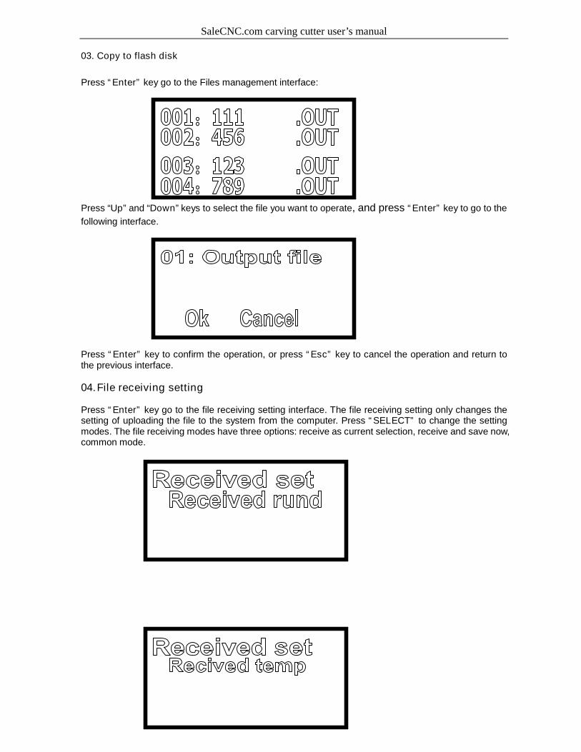
04.File receiving setting
Press “Enter” key go to the file receiving setting interface. The file receiving setting only changes thesetting of uploading the file to the system from the computer. Press “SELECT” to change the settingmodes. The file receiving modes have three options: receive as current selection, receive and save now,common mode.
SaleCNC.com carving cutter user’s manual
11
GuangZhou City,ChinaE-mail:[email protected]
1. Receive as current selection: The received file becomes the currently working file automatically,namely after the receiving operation, press “Start” to start engraving the current file.
2. Receive and save now: The received file will overlap the last file displayed in the Files completely.3. Common mode: Like the file copied from the flash disk, the received file is displayed as the last file
in the Files.
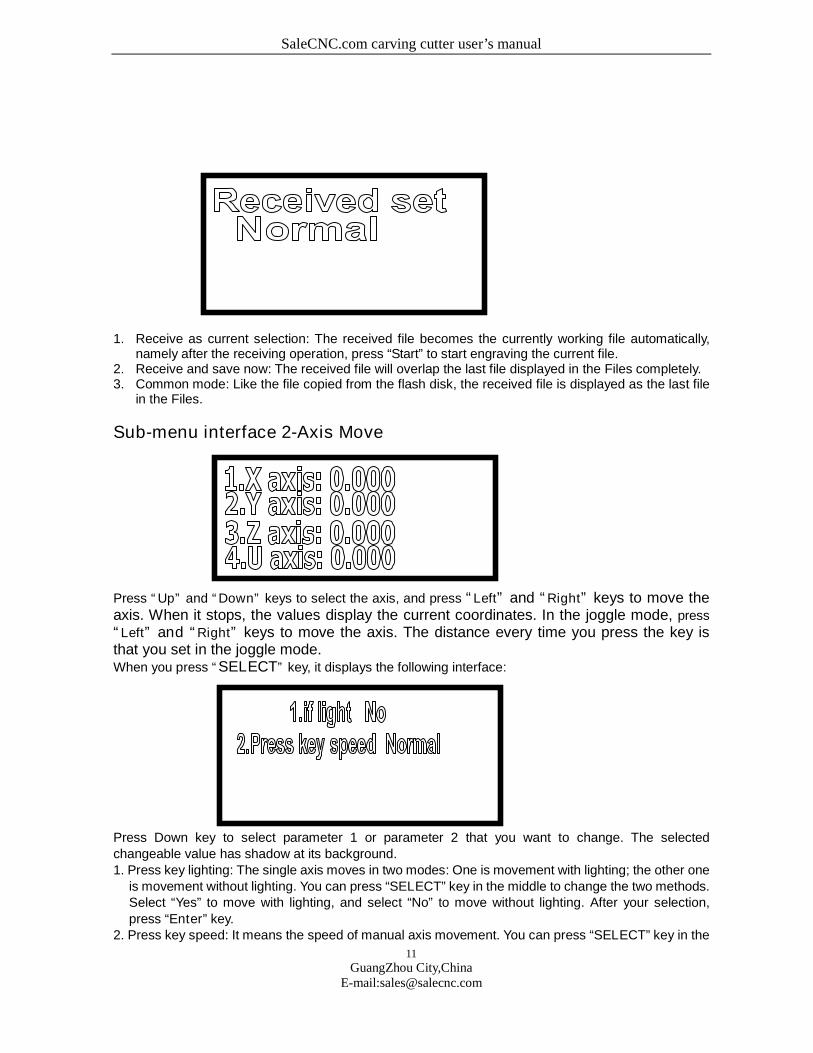
Sub-menu interface 2-Axis Move
Press “Up” and “Down” keys to select the axis, and press “Left” and “Right” keys to move theaxis. When it stops, the values display the current coordinates. In the joggle mode, press
“Left” and “Right” keys to move the axis. The distance every time you press the key isthat you set in the joggle mode.When you press “SELECT” key, it displays the following interface:
Press Down key to select parameter 1 or parameter 2 that you want to change. The selectedchangeable value has shadow at its background.1. Press key lighting: The single axis moves in two modes: One is movement with lighting; the other one
is movement without lighting. You can press “SELECT” key in the middle to change the two methods.Select “Yes” to move with lighting, and select “No” to move without lighting. After your selection,press “Enter” key.
2. Press key speed: It means the speed of manual axis movement. You can press “SELECT” key in the
SaleCNC.com carving cutter user’s manual
12
GuangZhou City,ChinaE-mail:[email protected]
middle to change the axis movement speed: “Fast”, “Normal” and “Low”.
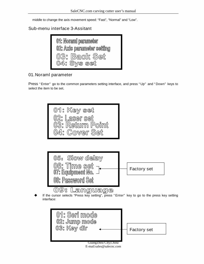
Sub-menu interface 3-Assitant
01.Noraml parameter
Press “Enter” go to the common parameters setting interface, and press “Up” and “Down” keys to
select the item to be set.
If the cursor selects “Press key setting”, press “Enter” key to go to the press key settinginterface:
Factory set
Factory set
SaleCNC.com carving cutter user’s manual
13
GuangZhou City,ChinaE-mail:[email protected]
A. If the cursor selects “Continuous mode”, press “Enter” key to go to the continuousmode setting interface. Press “SELECT” key to change the setting. The continuousmode setting only has two options: Disable and Enable.
B. If the cursor selects “Joggle mode”, press “Enter” key to go to the joggle modesetting interface. It can set the distance that the axis moves every time you press theaxis movement key. 0≦distance value≦100, in mm.
C. If the cursor selects “Press key polarity”, press “Enter” key to go to the press keypolarity setting interface. The panel’s direction keys correspond to the axis movementdirections. If you press Left key, but it moves rightwards, you only need to change thepolarity and then press “SELECT” key.
If the cursor selects “Laser setting”, press “Enter” key to go to the laser setting interface:
A. If the cursor selects “Joggle lighting setting”, press “Enter” key to go to the joggle lightingsetting and display the value setting interface. Here, you can set the joggle lighting time.When you press “Pulse” key for a long time, the time is the joggle lighting time, in S.
B. If the cursor selects “PWM polarity”, press “Enter” key to go to the PWM polarity setting. Ifyou find that the actual the lighting intensity increases when the intensity becomes lower.You only need to press “SELECT” key to change the PWM polarity, and then press“Enter” key.
C. If the cursor select ““PWM frequency”, press “Enter” key to go to the PWM frequencysetting and display the value setting interface. Here, you can set PWM frequency.
D. If the cursor selects “Duty ratio setting”, press “Enter” key to go to the duty ratio settinginterface, set the maximum/minimum duty ratio, and display the value setting interface.Here, you can set the duty ratio. Duty ratio setting range: 0≦minimum duty ratio≦maximum duty ratio ≦100. If the maximum duty ratio is equal to the minimum duty ratio,the intensity can’t be adjusted.
E. If the cursor selects “Laser type”, press “Enter” key to go to the laser typesetting interfaceand display value setting interface. Here, you can set the laser type.
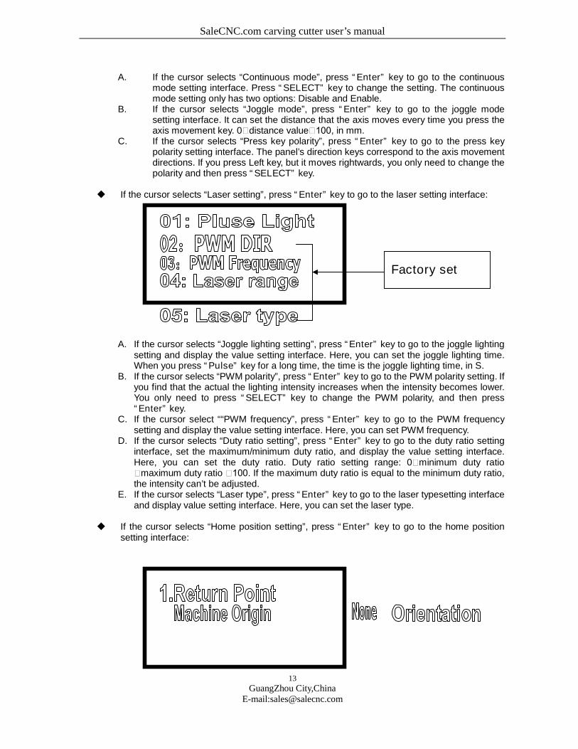
If the cursor selects “Home position setting”, press “Enter” key to go to the home positionsetting interface:
Factory set
SaleCNC.com carving cutter user’s manual
14
GuangZhou City,ChinaE-mail:[email protected]
Press “SELECT” key to change the setting. The home position has three options: mechanical origin,none, locating point.
Home position: It means the location where the laser head finally stays after the equipment
operation or the reset operation.
Mechanical origin: After the equipment operation or the reset operation, the laser head stays in the
mechanical origin;
None: After the equipment operation, the laser head stays in the last location after the operation;
Locating point: After the equipment operation or the reset operation, the laser head stays in the user
newly defined locating point.
If the mechanical origin coincides with the locating point, the two options are equivalent. The user can
make selection based on his/her own habit.
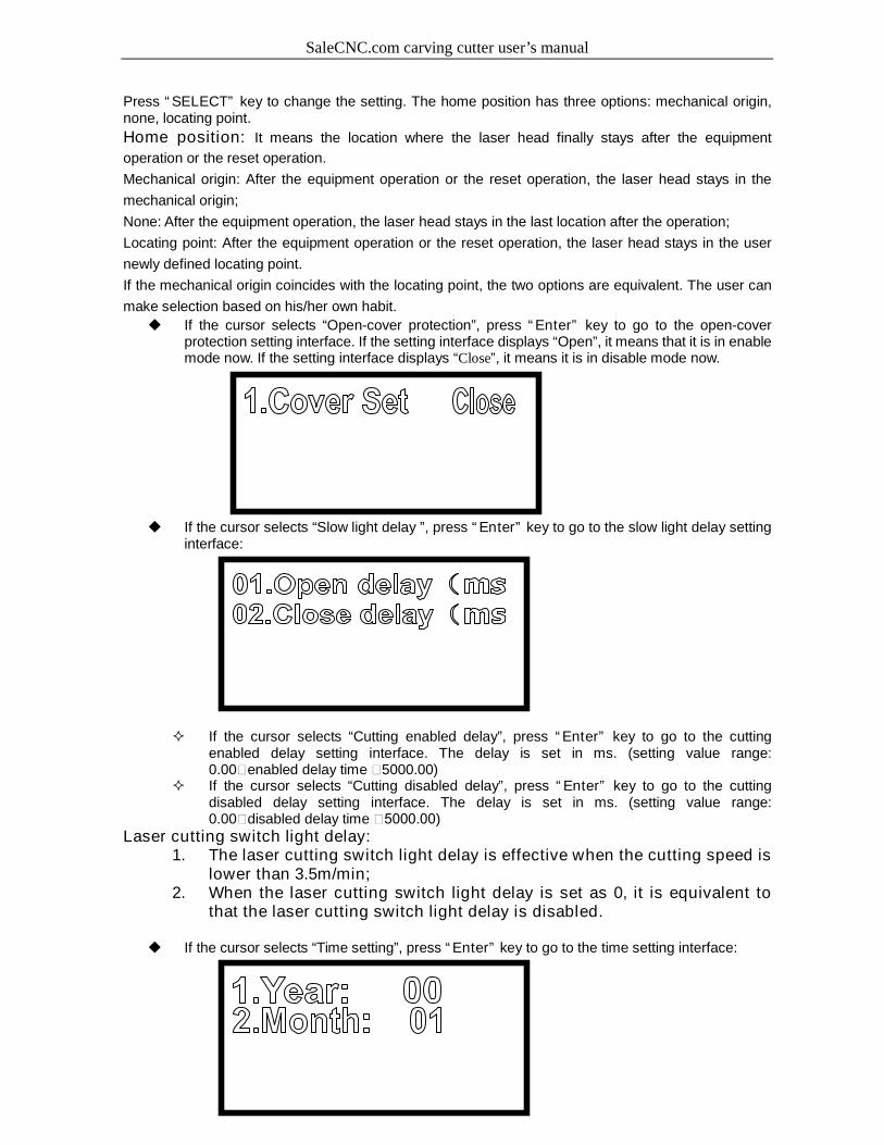
If the cursor selects “Open-cover protection”, press “Enter” key to go to the open-coverprotection setting interface. If the setting interface displays “Open”, it means that it is in enablemode now. If the setting interface displays “Close”, it means it is in disable mode now.
If the cursor selects “Slow light delay ”, press “Enter” key to go to the slow light delay settinginterface:
If the cursor selects “Cutting enabled delay”, press “Enter” key to go to the cuttingenabled delay setting interface. The delay is set in ms. (setting value range:0.00≦enabled delay time ≦5000.00)
If the cursor selects “Cutting disabled delay”, press “Enter” key to go to the cuttingdisabled delay setting interface. The delay is set in ms. (setting value range:0.00≦disabled delay time ≦5000.00)
Laser cutting switch light delay:1. The laser cutting switch light delay is effective when the cutting speed is
lower than 3.5m/min;2. When the laser cutting switch light delay is set as 0, it is equivalent to
that the laser cutting switch light delay is disabled.
If the cursor selects “Time setting”, press “Enter” key to go to the time setting interface:
SaleCNC.com carving cutter user’s manual
15
GuangZhou City,ChinaE-mail:[email protected]
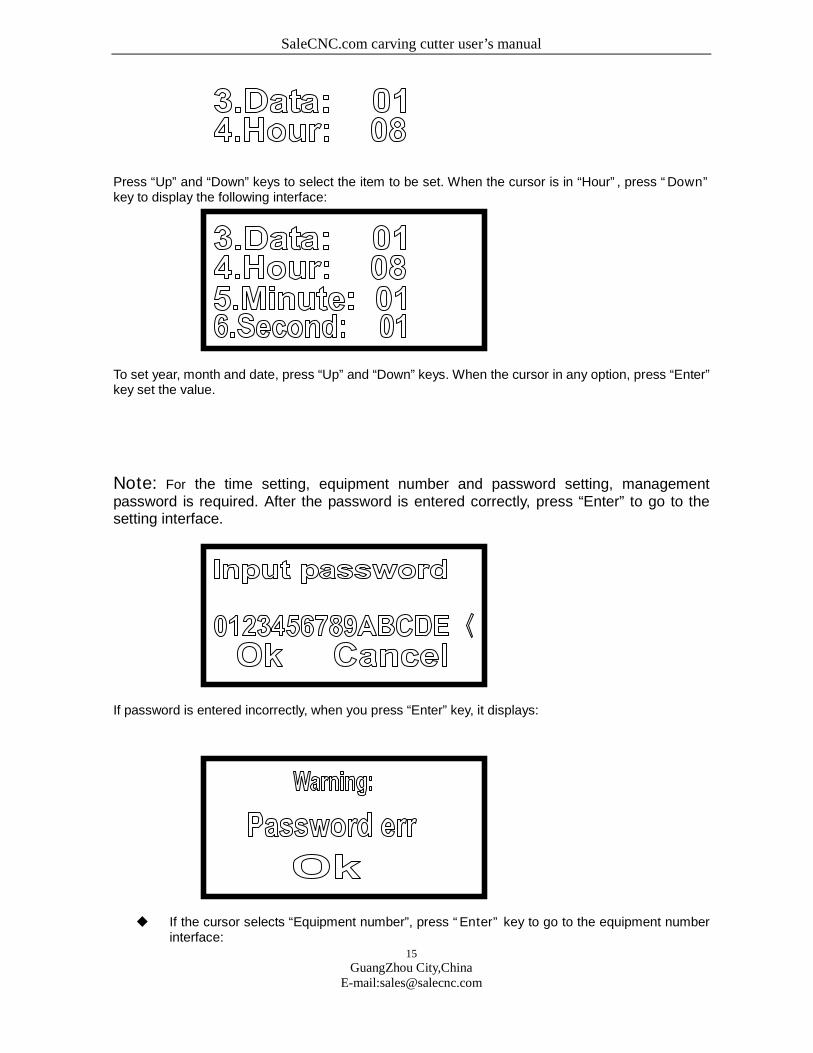
Press “Up” and “Down” keys to select the item to be set. When the cursor is in “Hour”, press “Down”key to display the following interface:
To set year, month and date, press “Up” and “Down” keys. When the cursor in any option, press “Enter”key set the value.
Note: For the time setting, equipment number and password setting, managementpassword is required. After the password is entered correctly, press “Enter” to go to thesetting interface.
If password is entered incorrectly, when you press “Enter” key, it displays:
If the cursor selects “Equipment number”, press “Enter” key to go to the equipment numberinterface:
SaleCNC.com carving cutter user’s manual
16
GuangZhou City,ChinaE-mail:[email protected]
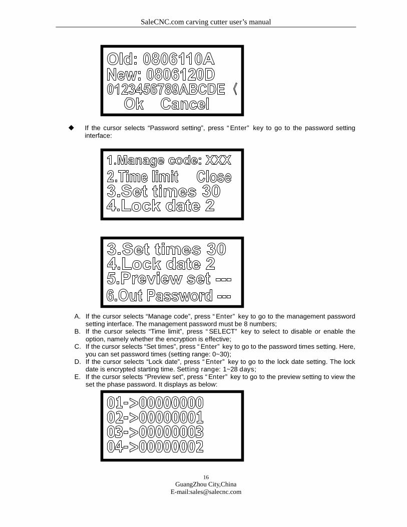
If the cursor selects “Password setting”, press “Enter” key to go to the password settinginterface:
A. If the cursor selects “Manage code”, press “Enter” key to go to the management passwordsetting interface. The management password must be 8 numbers;
B. If the cursor selects “Time limit”, press “SELECT” key to select to disable or enable theoption, namely whether the encryption is effective;
C. If the cursor selects “Set times”, press “Enter” key to go to the password times setting. Here,you can set password times (setting range: 0~30);
D. If the cursor selects “Lock date”, press “Enter” key to go to the lock date setting. The lockdate is encrypted starting time. Setting range: 1~28 days;
E. If the cursor selects “Preview set”, press “Enter” key to go to the preview setting to view theset the phase password. It displays as below:
SaleCNC.com carving cutter user’s manual
17
GuangZhou City,ChinaE-mail:[email protected]
F. If the cursor selects “Out Password”, when the flash disk is inserted, press “Enter” key toexport the password text file.
Note: This system can encrypt the hardware by phases. The phase number (passwordtimes) is 30 at most. The time of each phase is one month. The password is exported andsaved in the flash disk.
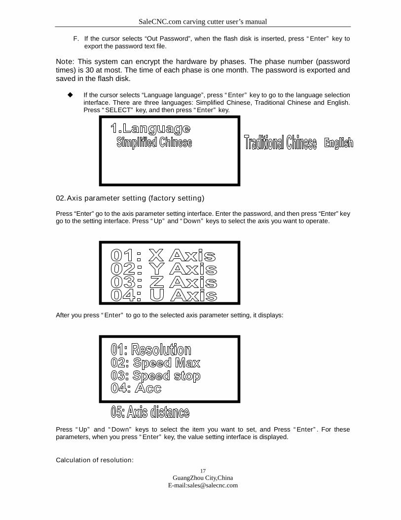
If the cursor selects “Language language”, press “Enter” key to go to the language selectioninterface. There are three languages: Simplified Chinese, Traditional Chinese and English.Press “SELECT” key, and then press “Enter” key.
02.Axis parameter setting (factory setting)
Press “Enter” go to the axis parameter setting interface. Enter the password, and then press “Enter” keygo to the setting interface. Press “Up” and “Down” keys to select the axis you want to operate.
After you press “Enter” to go to the selected axis parameter setting, it displays:
Press “Up” and “Down” keys to select the item you want to set, and Press “Enter”. For theseparameters, when you press “Enter” key, the value setting interface is displayed.
Calculation of resolution:
SaleCNC.com carving cutter user’s manual
18
GuangZhou City,ChinaE-mail:[email protected]
Accurate resolution = current resolution ×actual size /theoretical size
Current resolution: It means the resolution value set in the current operation, namely the resolution of
the equipment’s parameter setting, which can be read from the equipment.
Theoretical length: It means the length of effect drawing designed by the user, generally is integer,
which shall not exceed the maximum travel.
Actual length: It means the length of the track that the engraving machine leaves on the engraving
material, which can be measured by meter.
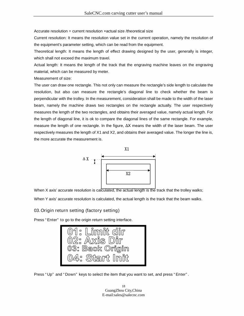
Measurement of size:
The user can draw one rectangle. This not only can measure the rectangle’s side length to calculate the
resolution, but also can measure the rectangle’s diagonal line to check whether the beam is
perpendicular with the trolley. In the measurement, consideration shall be made to the width of the laser
beam, namely the machine draws two rectangles on the rectangle actually. The user respectively
measures the length of the two rectangles, and obtains their averaged value, namely actual length. For
the length of diagonal line, it is ok to compare the diagonal lines of the same rectangle. For example,
measure the length of one rectangle. In the figure, ΔX means the width of the laser beam. The user
respectively measures the length of X1 and X2, and obtains their averaged value. The longer the line is,
the more accurate the measurement is.
When X axis’ accurate resolution is calculated, the actual length is the track that the trolley walks;
When Y axis’ accurate resolution is calculated, the actual length is the track that the beam walks.
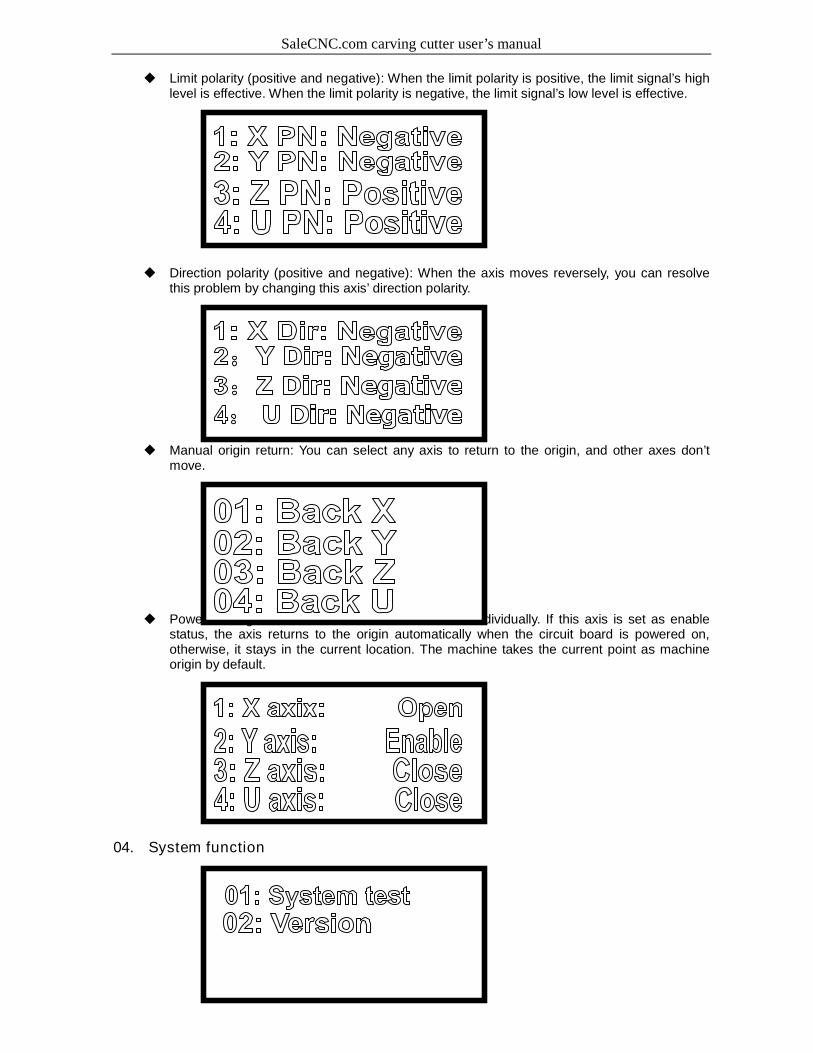
03.Origin return setting (factory setting)
Press “Enter” to go to the origin return setting interface.
Press “Up” and “Down” keys to select the item that you want to set, and press “Enter”.
X2
ΔX
X1
SaleCNC.com carving cutter user’s manual
19
GuangZhou City,ChinaE-mail:[email protected]
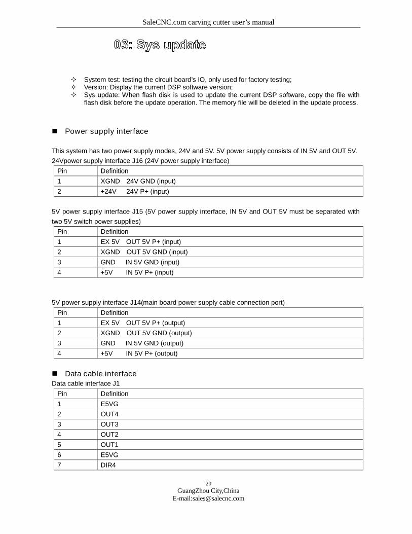
Limit polarity (positive and negative): When the limit polarity is positive, the limit signal’s highlevel is effective. When the limit polarity is negative, the limit signal’s low level is effective.
Direction polarity (positive and negative): When the axis moves reversely, you can resolvethis problem by changing this axis’ direction polarity.
Manual origin return: You can select any axis to return to the origin, and other axes don’tmove.
Power-on origin return: You can set the four axes individually. If this axis is set as enablestatus, the axis returns to the origin automatically when the circuit board is powered on,otherwise, it stays in the current location. The machine takes the current point as machineorigin by default.
04. System function
SaleCNC.com carving cutter user’s manual
20
GuangZhou City,ChinaE-mail:[email protected]
System test: testing the circuit board’s IO, only used for factory testing; Version: Display the current DSP software version; Sys update: When flash disk is used to update the current DSP software, copy the file with
flash disk before the update operation. The memory file will be deleted in the update process.
Power supply interface
This system has two power supply modes, 24V and 5V. 5V power supply consists of IN 5V and OUT 5V.
24Vpower supply interface J16 (24V power supply interface)
Pin Definition
1 XGND 24V GND (input)
2 +24V 24V P+ (input)
5V power supply interface J15 (5V power supply interface, IN 5V and OUT 5V must be separated with
two 5V switch power supplies)
Pin Definition
1 EX 5V OUT 5V P+ (input)
2 XGND OUT 5V GND (input)
3 GND IN 5V GND (input)
4 +5V IN 5V P+ (input)
5V power supply interface J14(main board power supply cable connection port)
Pin Definition
1 EX 5V OUT 5V P+ (output)
2 XGND OUT 5V GND (output)
3 GND IN 5V GND (output)
4 +5V IN 5V P+ (output)
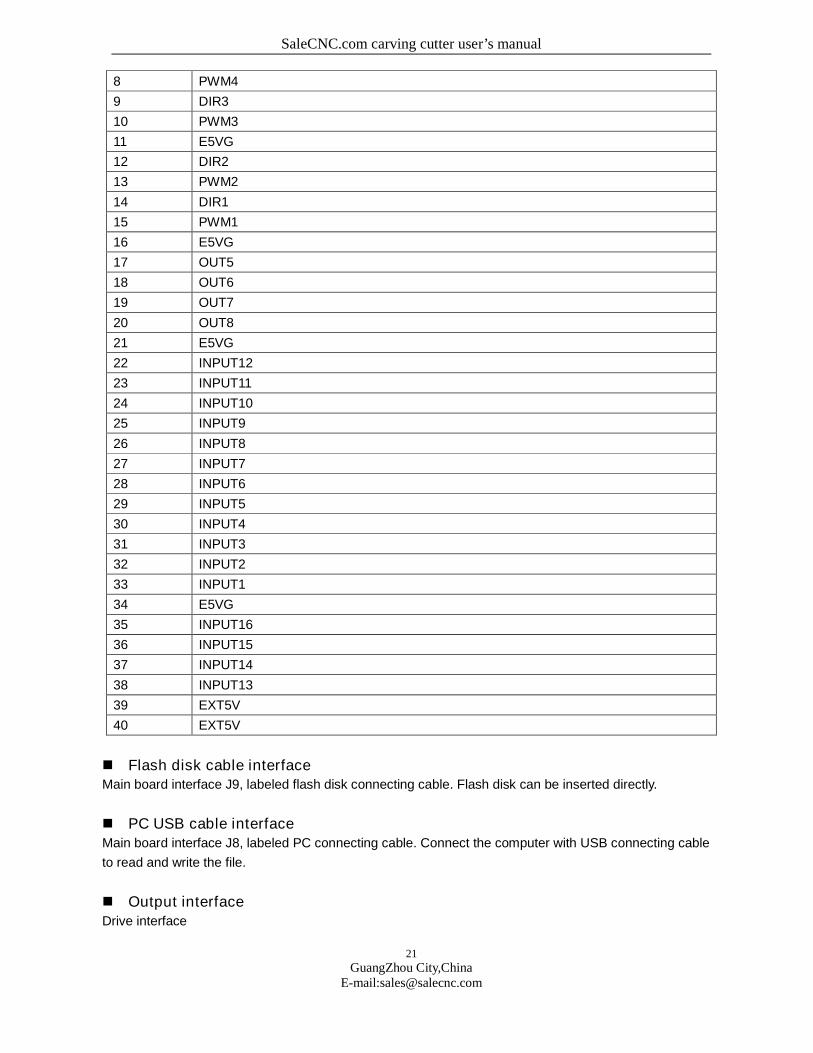
Data cable interfaceData cable interface J1
Pin Definition
1 E5VG
2 OUT4
3 OUT3
4 OUT2
5 OUT1
6 E5VG
7 DIR4
SaleCNC.com carving cutter user’s manual
21
GuangZhou City,ChinaE-mail:[email protected]
8 PWM4
9 DIR3
10 PWM3
11 E5VG
12 DIR2
13 PWM2
14 DIR1
15 PWM1
16 E5VG
17 OUT5
18 OUT6
19 OUT7
20 OUT8
21 E5VG
22 INPUT12
23 INPUT11
24 INPUT10
25 INPUT9
26 INPUT8
27 INPUT7
28 INPUT6
29 INPUT5
30 INPUT4
31 INPUT3
32 INPUT2
33 INPUT1
34 E5VG
35 INPUT16
36 INPUT15
37 INPUT14
38 INPUT13
39 EXT5V
40 EXT5V
Flash disk cable interfaceMain board interface J9, labeled flash disk connecting cable. Flash disk can be inserted directly.
PC USB cable interfaceMain board interface J8, labeled PC connecting cable. Connect the computer with USB connecting cable
to read and write the file.
Output interfaceDrive interface

SaleCNC.com carving cutter user’s manual
22
GuangZhou City,ChinaE-mail:[email protected]
X axis interface J2
Pin Definition
1 EX5V OUT 5V P+ (output)
2 PWM1 Stepping pulse (output)
3 DR1 Direction signal (output)
4 X GND OUT 5V GND (output)
Y axis interface J3
Pin Definition
1 EX5V OUT 5V P+ (output)
2 PWM2 Stepping pulse (output)
3 DR2 Direction signal (output)
4 X GND OUT 5V GND (output)
Z axis interface J4
Pin Definition
1 EX5V OUT 5V P+ (output)
2 OUT1 Stepping pulse (output)
3 OUT2 Direction signal (output)
4 X GND OUT 5V GND (output)
U axis interface J5
Pin Definition
1 EX5V OUT 5V P+ (output)
2 OUT3 Stepping pulse (output)
3 OUT4 Direction signal (output)
4 X GND OUT 5V GND (output)
General output interface
General IO output interface J6 (Expansion port)
Pin Definition
1 EX5V OUT 5V P+ (output)
2 OUT5
3 OUT6
4 X GND OUT 5V GND (output)
Relay control signal interface J7
Pin Definition
1 Relay OUT P+ (Relay power supply optional, 0-36V)
2 OUT7 In pen drawing mode, pen rising signal, relay output signal pin 1
3 OUT8 Blowing signal, relay output signal pin 1
SaleCNC.com carving cutter user’s manual
23
GuangZhou City,ChinaE-mail:[email protected]
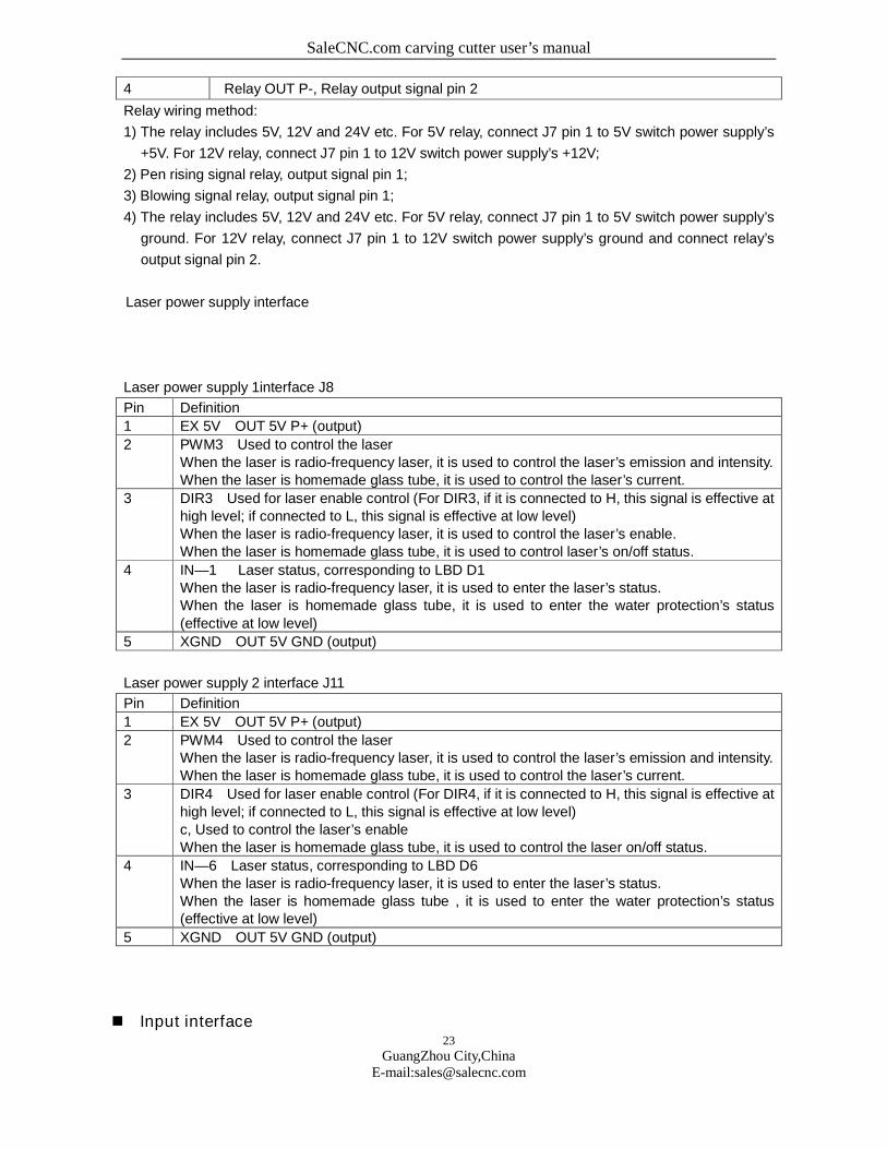
4 Relay OUT P-, Relay output signal pin 2
Relay wiring method:
1) The relay includes 5V, 12V and 24V etc. For 5V relay, connect J7 pin 1 to 5V switch power supply’s
+5V. For 12V relay, connect J7 pin 1 to 12V switch power supply’s +12V;
2) Pen rising signal relay, output signal pin 1;
3) Blowing signal relay, output signal pin 1;
4) The relay includes 5V, 12V and 24V etc. For 5V relay, connect J7 pin 1 to 5V switch power supply’s
ground. For 12V relay, connect J7 pin 1 to 12V switch power supply’s ground and connect relay’s
output signal pin 2.
Laser power supply interface
Laser power supply 1interface J8
Pin Definition
1 EX 5V OUT 5V P+ (output)
2 PWM3 Used to control the laserWhen the laser is radio-frequency laser, it is used to control the laser’s emission and intensity.When the laser is homemade glass tube, it is used to control the laser’s current.
3 DIR3 Used for laser enable control (For DIR3, if it is connected to H, this signal is effective athigh level; if connected to L, this signal is effective at low level)When the laser is radio-frequency laser, it is used to control the laser’s enable.When the laser is homemade glass tube, it is used to control laser’s on/off status.
4 IN—1 Laser status, corresponding to LBD D1When the laser is radio-frequency laser, it is used to enter the laser’s status.When the laser is homemade glass tube, it is used to enter the water protection’s status(effective at low level)
5 XGND OUT 5V GND (output)
Laser power supply 2 interface J11
Pin Definition
1 EX 5V OUT 5V P+ (output)
2 PWM4 Used to control the laserWhen the laser is radio-frequency laser, it is used to control the laser’s emission and intensity.When the laser is homemade glass tube, it is used to control the laser’s current.
3 DIR4 Used for laser enable control (For DIR4, if it is connected to H, this signal is effective athigh level; if connected to L, this signal is effective at low level)c, Used to control the laser’s enableWhen the laser is homemade glass tube, it is used to control the laser on/off status.
4 IN—6 Laser status, corresponding to LBD D6When the laser is radio-frequency laser, it is used to enter the laser’s status.When the laser is homemade glass tube , it is used to enter the water protection’s status(effective at low level)
5 XGND OUT 5V GND (output)
Input interface
SaleCNC.com carving cutter user’s manual
24
GuangZhou City,ChinaE-mail:[email protected]
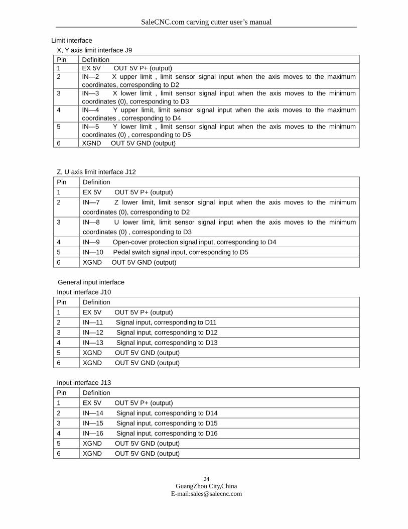
Limit interface
X, Y axis limit interface J9
Pin Definition
1 EX 5V OUT 5V P+ (output)
2 IN—2 X upper limit , limit sensor signal input when the axis moves to the maximumcoordinates, corresponding to D2
3 IN—3 X lower limit , limit sensor signal input when the axis moves to the minimumcoordinates (0), corresponding to D3
4 IN—4 Y upper limit, limit sensor signal input when the axis moves to the maximumcoordinates , corresponding to D4
5 IN—5 Y lower limit , limit sensor signal input when the axis moves to the minimumcoordinates (0) , corresponding to D5
6 XGND OUT 5V GND (output)
Z, U axis limit interface J12
Pin Definition
1 EX 5V OUT 5V P+ (output)
2 IN—7 Z lower limit, limit sensor signal input when the axis moves to the minimum
coordinates (0), corresponding to D2
3 IN—8 U lower limit, limit sensor signal input when the axis moves to the minimum
coordinates (0) , corresponding to D3
4 IN—9 Open-cover protection signal input, corresponding to D4
5 IN—10 Pedal switch signal input, corresponding to D5
6 XGND OUT 5V GND (output)
General input interface
Input interface J10
Pin Definition
1 EX 5V OUT 5V P+ (output)
2 IN—11 Signal input, corresponding to D11
3 IN—12 Signal input, corresponding to D12
4 IN—13 Signal input, corresponding to D13
5 XGND OUT 5V GND (output)
6 XGND OUT 5V GND (output)
Input interface J13
Pin Definition
1 EX 5V OUT 5V P+ (output)
2 IN—14 Signal input, corresponding to D14
3 IN—15 Signal input, corresponding to D15
4 IN—16 Signal input, corresponding to D16
5 XGND OUT 5V GND (output)
6 XGND OUT 5V GND (output)
SaleCNC.com carving cutter user’s manual
25
GuangZhou City,ChinaE-mail:[email protected]
*When single laser is used for control, the water protection signal of another laser control
must be short-connected with XGND, otherwise the machine can’t work normally.
*The switch input signal (IN) has the following wiring methods:
1. When proximity switch is used, for NPN normally open type, the upper computer’s
corresponding parameter must be set to “negative”; for PNP normally open type, the
upper computer’s corresponding parameter must be set to “positive”.
2. When pass switch or magnetic induction switch is used, for signal +XGND, the upper
computer’s corresponding parameter must be set to “negative”; for signal +EX5V. the
upper computer’s corresponding parameter must be set to “positive”.
3. Trouble and troubleshooting
3.1 Power-on reset
1. When the system is started, the system doesn’t reset, the press key doesn’t respond and
LCD has no display content.
Solution: Error occurs in the system power-on reset operation.
Step 1: Press “Emergency” key on the panel to check whether it is in normal status;
Step 2: Check whether the power supply OUT 5V and IN 5V is in normal status.
2. When the system is started, X axis and Y axis don’t move, LCD displays the main interface,
and the axis can be moved manually
Solution: The power-on origin return is set incorrectly. Go to the system’s power-on origin return
setting interface to set it to “Open”.
3. When the system is started, X axis and Y axis return to the origin, and LCD displays the
system initialization.
Solution: The power-on origin return is set incorrectly. Go to the system’s power-on origin return
setting interface to set Z axis and U axis to “Disable”.
4. When the system is started, after moving certain distance slowly, X axis and Y axis stop
before they reach the limit point. It is completed after reset.
Solution: The limit polarity is set incorrectly. Go to the system’s limit polarity setting interface to
change the limit polarity.
5. When the system is started, X axis and Y axis move towards the direction against the limit
switch.
Solution: The direction polarity is set incorrectly. Go to the system’s direction polarity setting

SaleCNC.com carving cutter user’s manual
26
GuangZhou City,ChinaE-mail:[email protected]
interface to change the direction polarity.
6. X axis and Y axis move in a direction against the press key’s direction.
Solution: The press key’s polarity is set incorrectly. Go to the system’s press key polarity setting
interface to change the press key polarity.
7. X axis and Y axis move immediately and automatically after the system is reset.
Solution: The home position is set incorrectly. Go to the home position setting interface to change
the home position to mechanical origin.
3.2 Laser emission
1. Power-on long emission
Solution: Check whether the enable signal of the laser power supply is wired. Check whether DIR3
and DIR4 on the interface board are consistent with the enable signal wire.
2. Emission becomes lower when the intensity is increased and becomes higher when the
intensity is decreased.
Solution: PWM polarity is set incorrectly. Go to the system press key polarity setting interface to
change PWM polarity.
3.3 Connection with the computer
Phenomenon:
1) When the parameters are read or written, the port can’t be opened;
2) The parameters can’t be read or written;
3) The transmitted file is invalid.
Solution:
1) Check whether USB cable is connected correctly and properly. Check whether USB cable’s
interface is connected to PC.
2) Check whether USB driver is installed correctly. Install the driver again.
3) Check the number of USB’s COM ports in the equipment management . If the port number is higher
than 9, change it to 3~9.
4) The software output port shall be the same with COM port.
5) Insert a good USB port on the computer.
6) Turn off the equipment’s power supply, and keep it for three minutes. Turn it on again.
7) Reboot the computer.
3.4 Flash disk
When you click the Flash Disk, the system displays “flash disk is empty or incorrect”.
Solution: Error occurs in the flash disk.
Step 1: Check whether the flash disk interface is correct;
Step 2: Change one new type of flash disk.
When you click the Flash Disk, the system displays “Reading… Please wait”, and the flash
disk’s indicator is off.
SaleCNC.com carving cutter user’s manual
27
GuangZhou City,ChinaE-mail:[email protected]
Solution: Change the flash disk cable.
3.5 Password setting
The exported password is invalid.
Solution: Error occurs when the password is exported to the flash disk automatically.
Step 1: Check whether the time limit is in “Open” status. The password can’t be exported unless it is in
“Open” status;
Step 2: Go to the file management status to check whether it can read the Flash Disk. If not, replace a
flash disk.
4. CorelDraw Direct Output
Preface
Applications: Providing supports for laser engraving motion control cards of
TopWisdom.
Operating platform: OS Window98, Window2000, and Windows XP.
Hardware: Celeron 500 or above, EMS memory above 128M, HD above 10G
Supporting CorelDraw11 and CorelDraw12
Functional advantages: TopWisdom laser engraving is installed on CorelDraw and
creates a menu on CorelDraw, which realized the seamless connection with CorelDraw
software, as a leading technology in the industry of the country, its greatest advantage is
that it utilized the strong edit function of CorelDraw and the users can draw and modify the
drawings directly on CorelDraw and then set various parameters on CorelDraw and
transmit the parameters directly to our motion control cards. Invoking another software to
connect the motion control card in stead of saving the CorelDraw files provides the users
with the most powerful and convenient functions, because we can utilize function of
CorelDraw, we are standing on the shoulders of a giant, which is a high starting point.
Furthermore, our software supports the popular CorelDraw11 and CorelDraw12, which is
most convenient to the users.
Description of functions: There are mainly 2 modes of laser engraving motion control system,
cutting and engraving. In term of software, engraving is corresponding to the setting of Clear and
cutting is corresponding to the setting of Stroke, so we focus the functions of our software on these 2
aspects. We can differentiate the settings by different colors, representing Stroke or Clear or
Stroke/Clear, and the order of work can be controlled. For Clear, we can realize gradient function and
compensation function, and for Stroke, we can realize seam width compensation, just input the seam
SaleCNC.com carving cutter user’s manual
28
GuangZhou City,ChinaE-mail:[email protected]
width when cutting by laser or tools, the software can automatically add the seam width, which realizes
the accurate of the actual dimensions. Besides, in case of nesting of drawings in the same color, the
cutting should be started from the inside to the outside according to the technical requirements (so that
succeeding cuttings will not be influenced by the cut part), we provide you with the setting of Inside to
Outside and this function can be realized after startup. Requirements for improving the efficiency and
cutting from the nearest place one by one can be achieved by the shortest path setting etc., If you
imported bitmap in CorelDraw, there will be a separate feature for the setting of bitmaps, bitmaps can
only be applied to Clear, you can make bitmaps like grids with software suitable for making bitmaps and
then import them into CorelDraw for output.
From what described above, we can easily find out the advantages of TopWisdom
laser engraving software: powerful and convenient.
Chapter 1: Software Installation
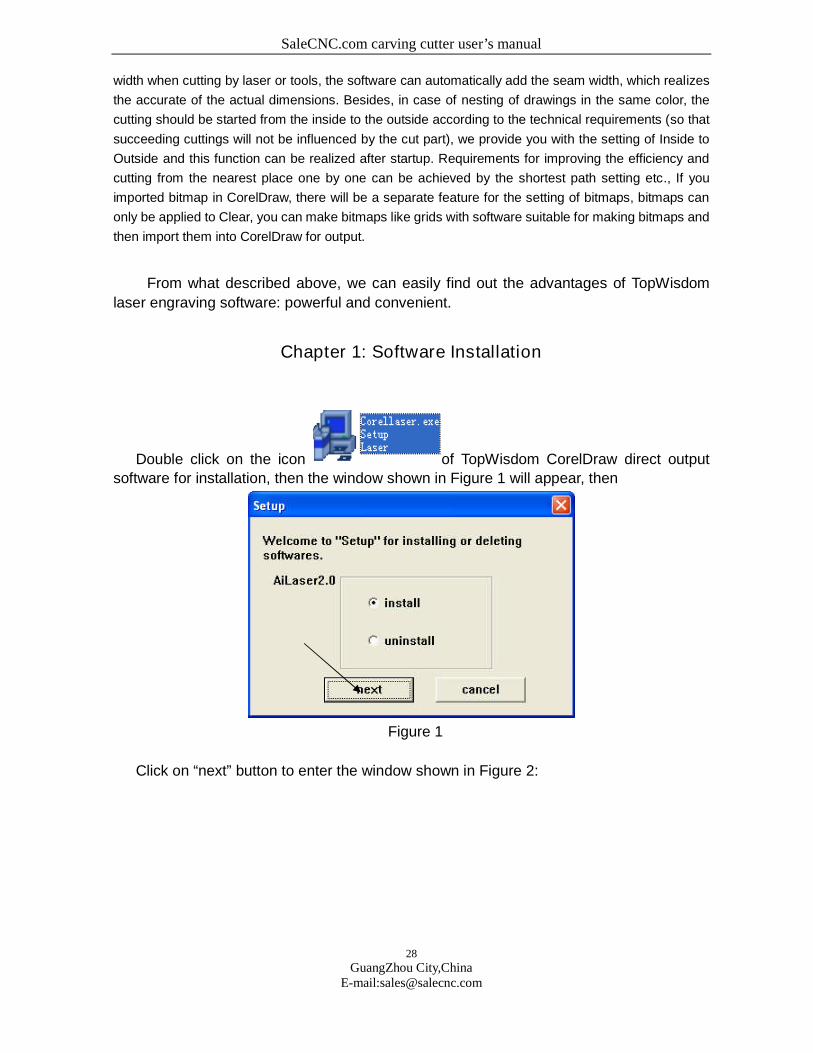
Double click on the icon of TopWisdom CorelDraw direct output
software for installation, then the window shown in Figure 1 will appear, then
Figure 1
Click on “next” button to enter the window shown in Figure 2:
SaleCNC.com carving cutter user’s manual
29
GuangZhou City,ChinaE-mail:[email protected]
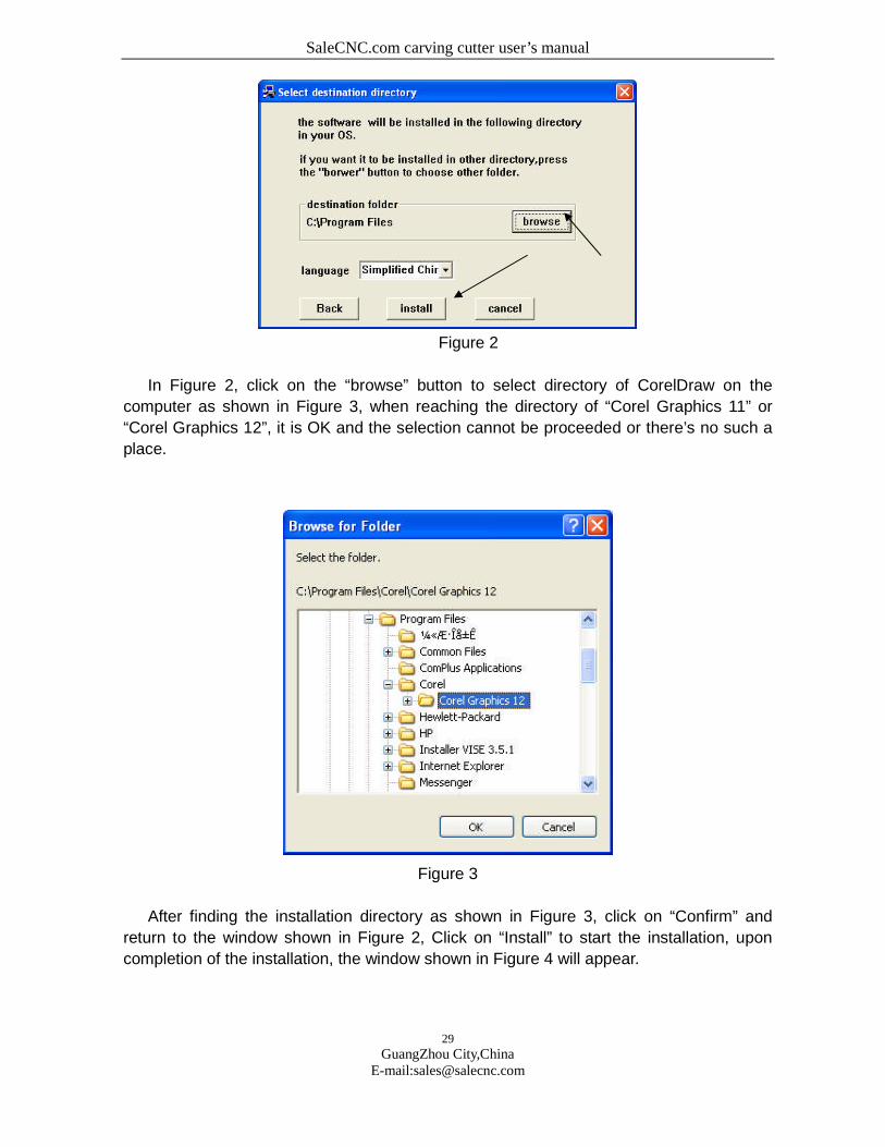
Figure 2
In Figure 2, click on the “browse” button to select directory of CorelDraw on the
computer as shown in Figure 3, when reaching the directory of “Corel Graphics 11” or
“Corel Graphics 12”, it is OK and the selection cannot be proceeded or there’s no such a
place.
Figure 3
After finding the installation directory as shown in Figure 3, click on “Confirm” and
return to the window shown in Figure 2, Click on “Install” to start the installation, upon
completion of the installation, the window shown in Figure 4 will appear.
SaleCNC.com carving cutter user’s manual
30
GuangZhou City,ChinaE-mail:[email protected]
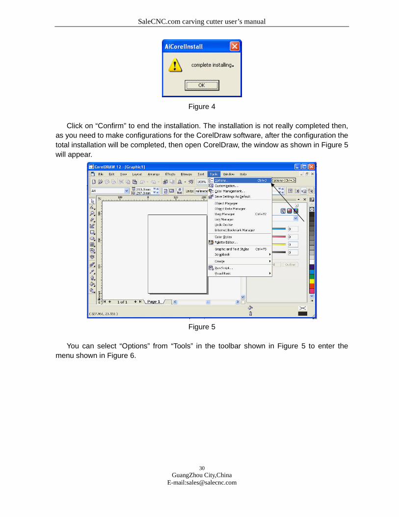
Figure 4
Click on “Confirm” to end the installation. The installation is not really completed then,
as you need to make configurations for the CorelDraw software, after the configuration the
total installation will be completed, then open CorelDraw, the window as shown in Figure 5
will appear.
Figure 5
You can select “Options” from “Tools” in the toolbar shown in Figure 5 to enter the
menu shown in Figure 6.
SaleCNC.com carving cutter user’s manual
31
GuangZhou City,ChinaE-mail:[email protected]
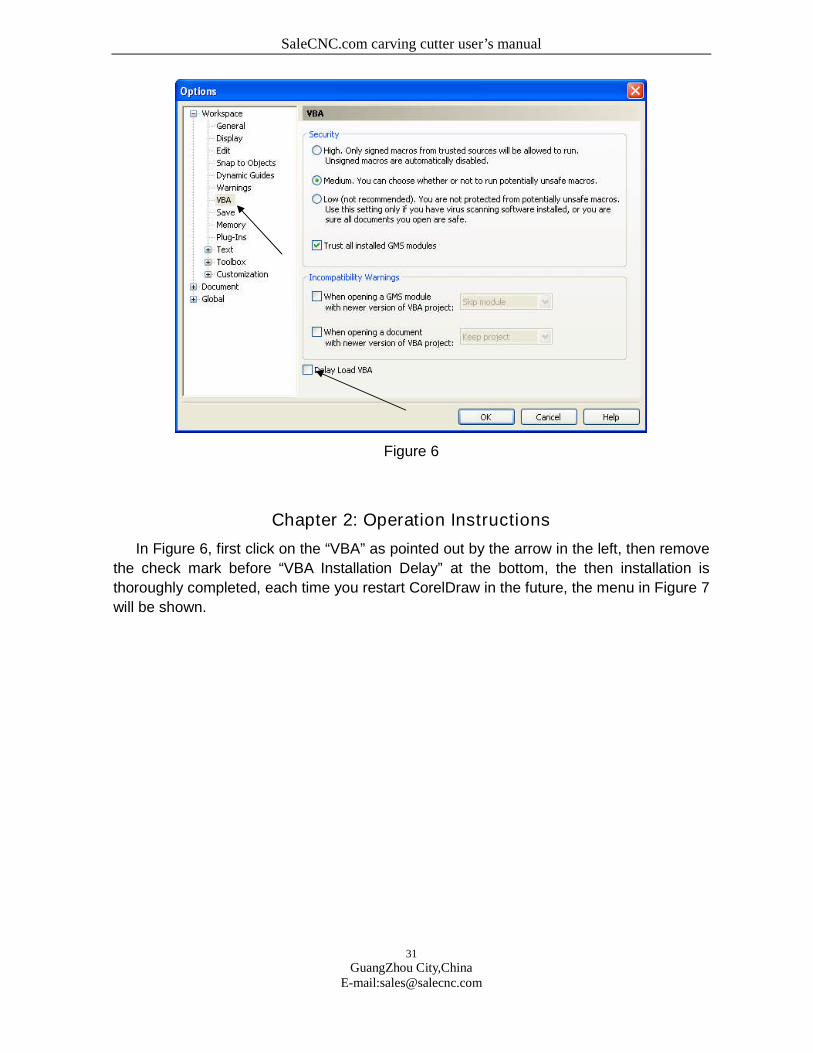
Figure 6
Chapter 2: Operation Instructions
In Figure 6, first click on the “VBA” as pointed out by the arrow in the left, then remove
the check mark before “VBA Installation Delay” at the bottom, the then installation is
thoroughly completed, each time you restart CorelDraw in the future, the menu in Figure 7
will be shown.
SaleCNC.com carving cutter user’s manual
32
GuangZhou City,ChinaE-mail:[email protected]
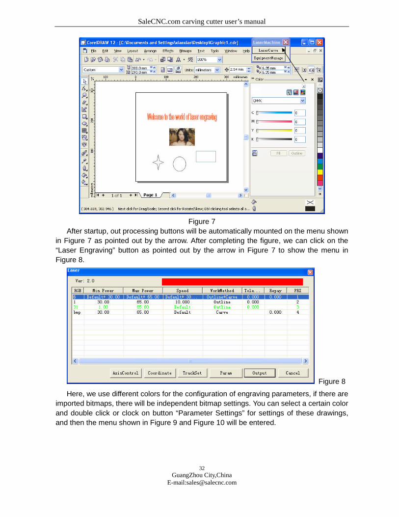
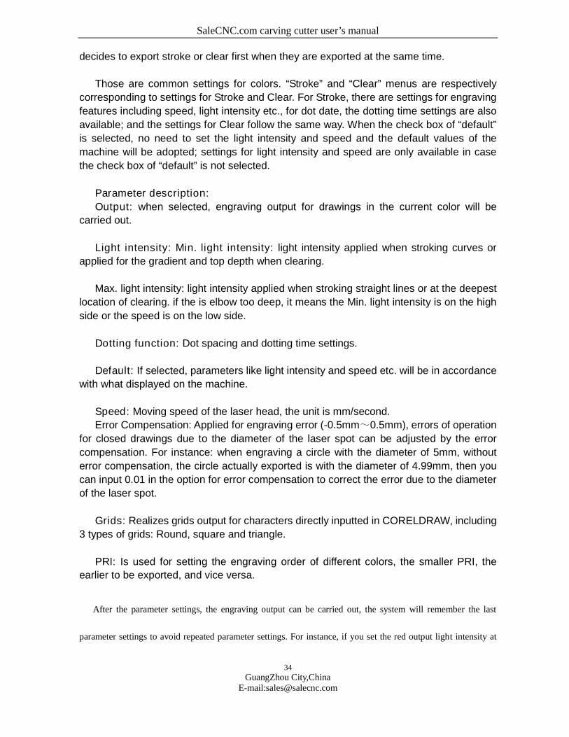
Figure 7
After startup, out processing buttons will be automatically mounted on the menu shown
in Figure 7 as pointed out by the arrow. After completing the figure, we can click on the
“Laser Engraving” button as pointed out by the arrow in Figure 7 to show the menu in
Figure 8.
Figure 8
Here, we use different colors for the configuration of engraving parameters, if there are
imported bitmaps, there will be independent bitmap settings. You can select a certain color
and double click or clock on button “Parameter Settings” for settings of these drawings,
and then the menu shown in Figure 9 and Figure 10 will be entered.

SaleCNC.com carving cutter user’s manual
33
GuangZhou City,ChinaE-mail:[email protected]
Figure 9
Figure 10
The two most important parameter settings are stroke output and clear output. If
neither of the two is selected, “output disabled” will be shown, i.e., no engraving output for
this kind of drawings will be carried out; if both are selected, data in this color will be
provided with possibility of both stroke and clear output, pay attention that there must be
closed drawings for clear. Otherwise, select one of them for one output condition.
Error compensation can realize shrinkage and extension for closed drawings according
to given numbers. PRI will define the output order of colors, stroke PRI or clear PRI
SaleCNC.com carving cutter user’s manual
34
GuangZhou City,ChinaE-mail:[email protected]
decides to export stroke or clear first when they are exported at the same time.
Those are common settings for colors. “Stroke” and “Clear” menus are respectively
corresponding to settings for Stroke and Clear. For Stroke, there are settings for engraving
features including speed, light intensity etc., for dot date, the dotting time settings are also
available; and the settings for Clear follow the same way. When the check box of “default”
is selected, no need to set the light intensity and speed and the default values of the
machine will be adopted; settings for light intensity and speed are only available in case
the check box of “default” is not selected.
Parameter description:
Output: when selected, engraving output for drawings in the current color will be
carried out.
Light intensity: Min. light intensity: light intensity applied when stroking curves or
applied for the gradient and top depth when clearing.
Max. light intensity: light intensity applied when stroking straight lines or at the deepest
location of clearing. if the is elbow too deep, it means the Min. light intensity is on the high
side or the speed is on the low side.
Dotting function: Dot spacing and dotting time settings.
Default: If selected, parameters like light intensity and speed etc. will be in accordance
with what displayed on the machine.
Speed: Moving speed of the laser head, the unit is mm/second.
Error Compensation: Applied for engraving error (-0.5mm~0.5mm), errors of operation
for closed drawings due to the diameter of the laser spot can be adjusted by the error
compensation. For instance: when engraving a circle with the diameter of 5mm, without
error compensation, the circle actually exported is with the diameter of 4.99mm, then you
can input 0.01 in the option for error compensation to correct the error due to the diameter
of the laser spot.
Grids: Realizes grids output for characters directly inputted in CORELDRAW, including
3 types of grids: Round, square and triangle.
PRI: Is used for setting the engraving order of different colors, the smaller PRI, the
earlier to be exported, and vice versa.
After the parameter settings, the engraving output can be carried out, the system will remember the last
parameter settings to avoid repeated parameter settings. For instance, if you set the red output light intensity at
SaleCNC.com carving cutter user’s manual
35
GuangZhou City,ChinaE-mail:[email protected]
(50%, speed at 20%, no error compensation and PRI at 1), the same setting will be applied for the use of the
color red (if any) for the next time.
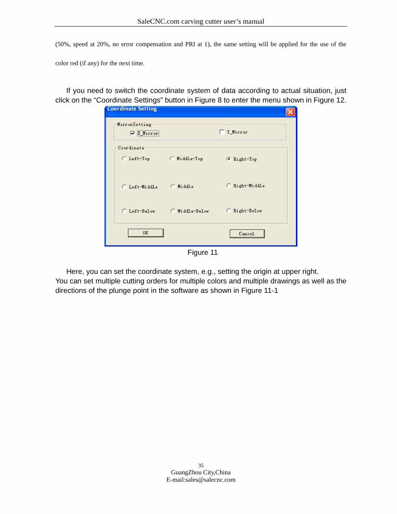
If you need to switch the coordinate system of data according to actual situation, just
click on the “Coordinate Settings” button in Figure 8 to enter the menu shown in Figure 12.
Figure 11
Here, you can set the coordinate system, e.g., setting the origin at upper right.
You can set multiple cutting orders for multiple colors and multiple drawings as well as the
directions of the plunge point in the software as shown in Figure 11-1

SaleCNC.com carving cutter user’s manual
36
GuangZhou City,ChinaE-mail:[email protected]
Figure 11-1
To change drawing 3 into the first cutting order, just select drawing 3 and input 1 in
cutting order and then click on Confirm.
You can operate the distance of moving in single axis in the software as shown in the figure:
Figure 11-2
You can set the moving distance of an axis separately for descending and ascending.
Then return to Figure 8, after the parameter settings, click on “output” to enter Figure 12
SaleCNC.com carving cutter user’s manual
37
GuangZhou City,ChinaE-mail:[email protected]
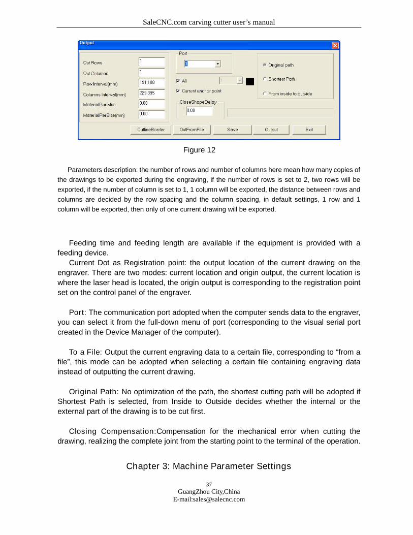
Figure 12
Parameters description: the number of rows and number of columns here mean how many copies of
the drawings to be exported during the engraving, if the number of rows is set to 2, two rows will be
exported, if the number of column is set to 1, 1 column will be exported, the distance between rows and
columns are decided by the row spacing and the column spacing, in default settings, 1 row and 1
column will be exported, then only of one current drawing will be exported.
Feeding time and feeding length are available if the equipment is provided with a
feeding device.
Current Dot as Registration point: the output location of the current drawing on the
engraver. There are two modes: current location and origin output, the current location is
where the laser head is located, the origin output is corresponding to the registration point
set on the control panel of the engraver.
Port: The communication port adopted when the computer sends data to the engraver,
you can select it from the full-down menu of port (corresponding to the visual serial port
created in the Device Manager of the computer).
To a File: Output the current engraving data to a certain file, corresponding to “from a
file”, this mode can be adopted when selecting a certain file containing engraving data
instead of outputting the current drawing.
Original Path: No optimization of the path, the shortest cutting path will be adopted if
Shortest Path is selected, from Inside to Outside decides whether the internal or the
external part of the drawing is to be cut first.
Closing Compensation:Compensation for the mechanical error when cutting the
drawing, realizing the complete joint from the starting point to the terminal of the operation.
Chapter 3: Machine Parameter Settings
SaleCNC.com carving cutter user’s manual
38
GuangZhou City,ChinaE-mail:[email protected]
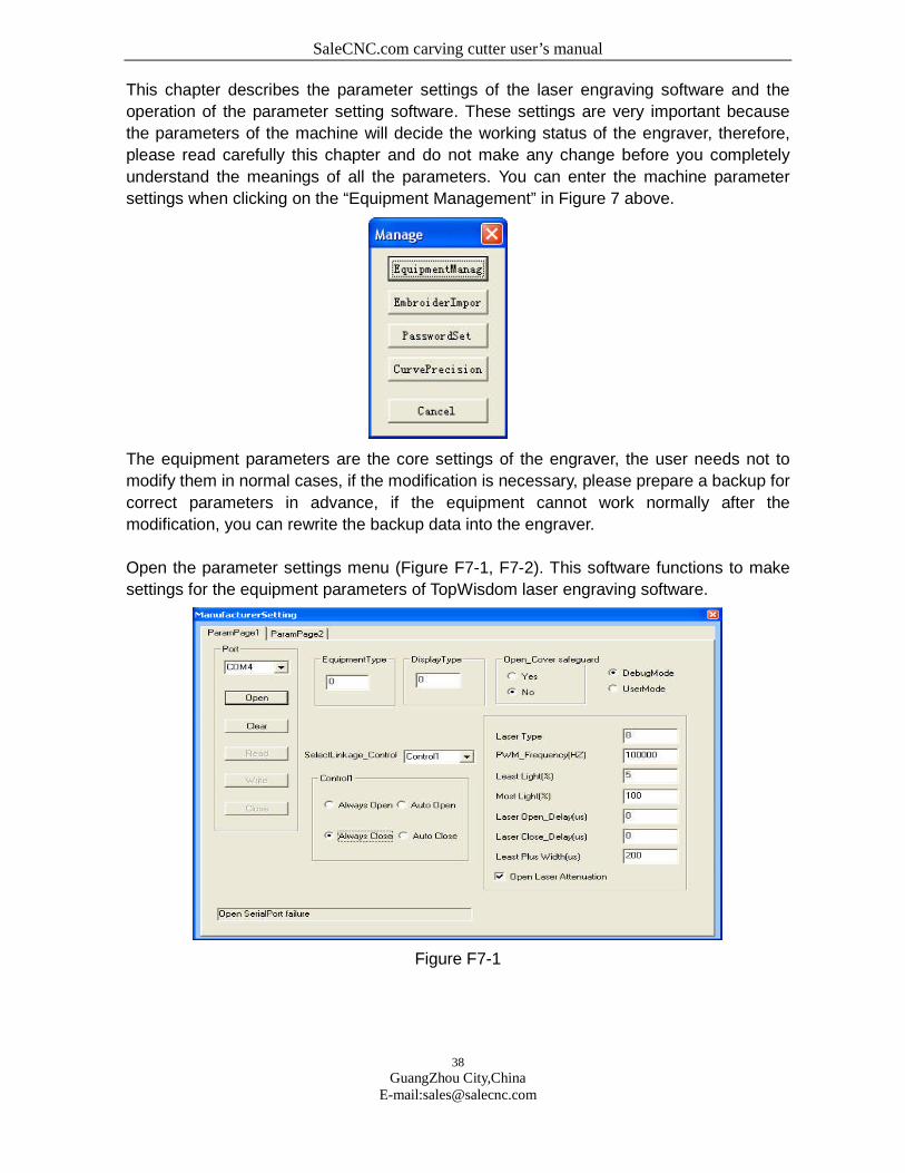
This chapter describes the parameter settings of the laser engraving software and the
operation of the parameter setting software. These settings are very important because
the parameters of the machine will decide the working status of the engraver, therefore,
please read carefully this chapter and do not make any change before you completely
understand the meanings of all the parameters. You can enter the machine parameter
settings when clicking on the “Equipment Management” in Figure 7 above.
The equipment parameters are the core settings of the engraver, the user needs not to
modify them in normal cases, if the modification is necessary, please prepare a backup for
correct parameters in advance, if the equipment cannot work normally after the
modification, you can rewrite the backup data into the engraver.
Open the parameter settings menu (Figure F7-1, F7-2). This software functions to make
settings for the equipment parameters of TopWisdom laser engraving software.
Figure F7-1
SaleCNC.com carving cutter user’s manual
39
GuangZhou City,ChinaE-mail:[email protected]
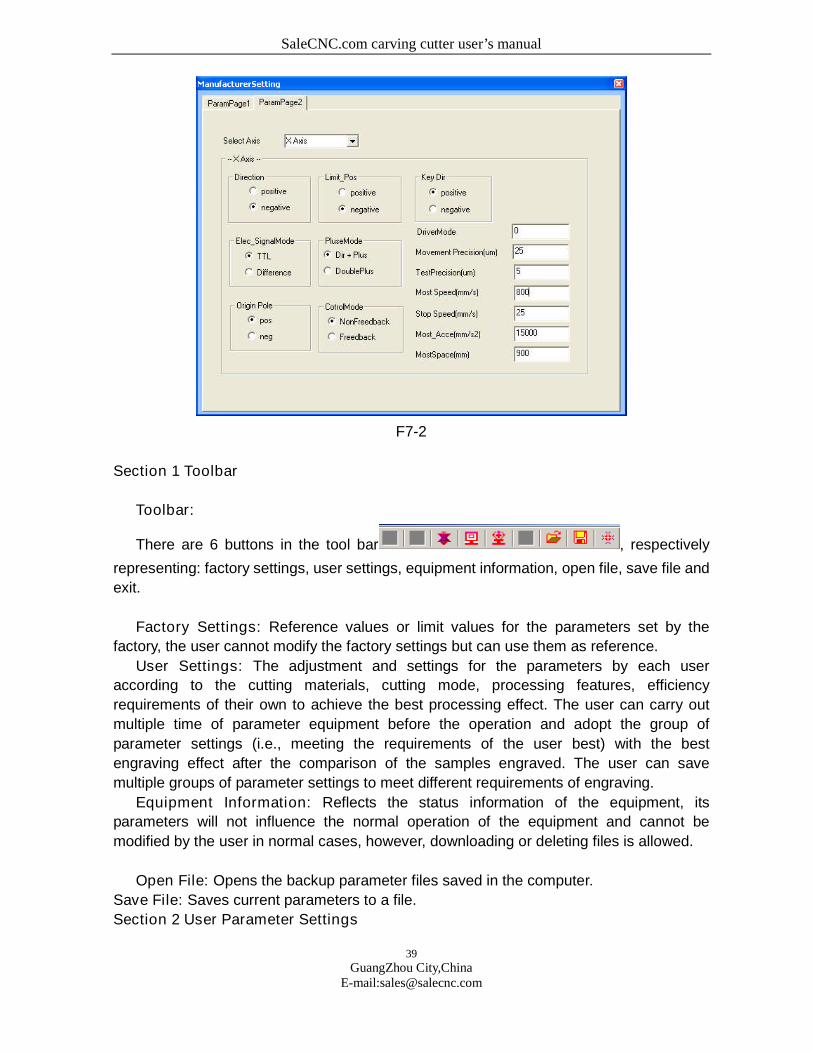
F7-2
Section 1 Toolbar
Toolbar:
There are 6 buttons in the tool bar , respectively
representing: factory settings, user settings, equipment information, open file, save file and
exit.
Factory Settings: Reference values or limit values for the parameters set by the
factory, the user cannot modify the factory settings but can use them as reference.
User Settings: The adjustment and settings for the parameters by each user
according to the cutting materials, cutting mode, processing features, efficiency
requirements of their own to achieve the best processing effect. The user can carry out
multiple time of parameter equipment before the operation and adopt the group of
parameter settings (i.e., meeting the requirements of the user best) with the best
engraving effect after the comparison of the samples engraved. The user can save
multiple groups of parameter settings to meet different requirements of engraving.
Equipment Information: Reflects the status information of the equipment, its
parameters will not influence the normal operation of the equipment and cannot be
modified by the user in normal cases, however, downloading or deleting files is allowed.
Open File: Opens the backup parameter files saved in the computer.
Save File: Saves current parameters to a file.
Section 2 User Parameter Settings
SaleCNC.com carving cutter user’s manual
40
GuangZhou City,ChinaE-mail:[email protected]
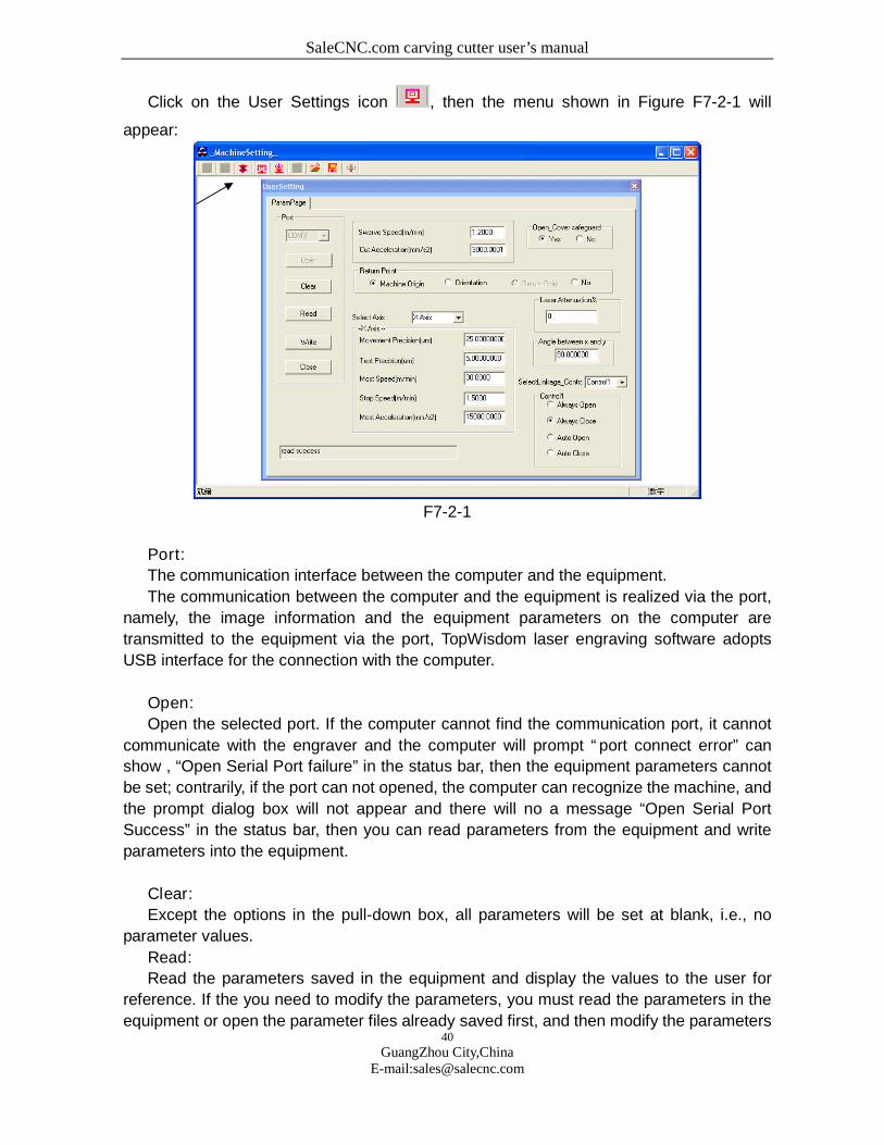
Click on the User Settings icon , then the menu shown in Figure F7-2-1 will
appear:
F7-2-1
Port:
The communication interface between the computer and the equipment.
The communication between the computer and the equipment is realized via the port,
namely, the image information and the equipment parameters on the computer are
transmitted to the equipment via the port, TopWisdom laser engraving software adopts
USB interface for the connection with the computer.
Open:
Open the selected port. If the computer cannot find the communication port, it cannot
communicate with the engraver and the computer will prompt “port connect error” can
show , “Open Serial Port failure” in the status bar, then the equipment parameters cannot
be set; contrarily, if the port can not opened, the computer can recognize the machine, and
the prompt dialog box will not appear and there will no a message “Open Serial Port
Success” in the status bar, then you can read parameters from the equipment and write
parameters into the equipment.
Clear:
Except the options in the pull-down box, all parameters will be set at blank, i.e., no
parameter values.
Read:
Read the parameters saved in the equipment and display the values to the user for
reference. If the you need to modify the parameters, you must read the parameters in the
equipment or open the parameter files already saved first, and then modify the parameters

SaleCNC.com carving cutter user’s manual
41
GuangZhou City,ChinaE-mail:[email protected]
(this button is disabled when "Open Serial Port Failure”).
Write:
Write the parameter values set by the user into the equipment (authorizing code
provided by the manufacture is required), and then the equipment will operate according to
the parameters written into it. When the parameter settings of the equipment is not
completed, click on this button, and the “Some Data is Invalidate” will be shown in the
status bar at the bottom, the parameters cannot be written into the machine.
The parameters will be valid once written into the machine except some special
parameters, which will be validated after switching off and restart the machine. (This
button is disabled when "Open Serial Port Failure”)
Close:
Close all ports opened, namely, cut the connection between the computer and the
equipment. “Close SerialPort” will be shown in the status bar.
※ TopWisdom software, downloading soft and parameter setting software will use
ports and one serial port will be used for the equipment for writing and reading, therefore,
once a kind of software is using a serial port, other software cannot use this serial port.
Speed at Inflexion (m/min):
Speed of the equipment at inflexion (a right angle, for instance). The speed at inflexion
will influence the effect of engraving.
If the speed at speed at inflexion is high, the curve will be sharp, and the impact to the
equipment will be great and thus the effect of engraving will be worse; if the speed at
speed at inflexion is low, the curve will be smooth and the equipment will run stably with
high accuracy, and thus the effect of engraving will be better, however, the efficiency will
be reduced.
The user can set suitable values according the requirements for accuracy.
Acceleration of Cutting(mm/S2):
The acceleration when the equipment is cutting (stroking). The acceleration of cutting
will influence the effect of cutting and efficiency of operation. If the acceleration of cutting is
high, the change of cutting speed is fast, the cutting efficiency will be high while the cutting
effect will be poor; If the acceleration of cutting is low, the change of cutting speed is slow,
the cutting efficiency will be low while the cutting effect will be good.
Home Position:
The location where the laser head finally stays after the operation is completed or
reset.
There are two radio buttons: Mechanical Origin and Location Dot.
If Mechanical Origin is selected, the laser head will stay at the mechanical origin after
the operation is completed or reset;

SaleCNC.com carving cutter user’s manual
42
GuangZhou City,ChinaE-mail:[email protected]
If Location Dot is selected, the laser head will stay at the dot defined by the user after
the operation is completed or reset.
If the mechanical origin and the registration point overlap, the two options will be
equivalent. You may make selection according to your own preference.
Select Axis:
The motion system of the engraver comprises X-axis, Y-axis, Z-axis, U-axis, V-axis,
W-axis and the feeding axis etc. (this may differ according to specific configuration of the
equipment), the user can make settings according to the actual conditions, e.g.,: if only
X-axis and Y-axis are required, you only need to set the parameters of X-axis and Y-axis; if
you need to control X-axis, Y-axis and Z-axis, you should set the parameters of the 3 axes.
Motion Resolution (µm):
The spacing between two neighboring dots, the unit is µm. The resolution of machines
may be changed slightly due to different abrasion and other factors of machines, the user
may get the optimal value after multiple times of debugging and settings.
Calculation of Resolution:
Accurate Resolution = Current Resolution × Actual Dimensions/Theoretical
Dimensions
Current Resolution: The resolution set at current operation of the equipment, i.e., the
resolution in the parameter settings of the equipment, which can be read from the
equipment.
Theoretical Length: The length on the effect drawing designed by the user, normally in
whole numbers but not exceeding the max. travel.
Actual Length: The length of the track left by the engraver on the engraved material,
which can be measured by measuring tools.
Measurement of dimensions:
The user may draw a rectangle, then the resolution can be calculate according to the
length and width of the rectangle, or you can check if the bean is normal to the dolly by
measuring the diagonal of the rectangle. When measuring, the width of the laser beam
should be taken into account, namely, the machine actually draws 2 rectangles, the user
should measure the lengths of the 2 rectangles respectively and the mean value of the 2
lengths is the actual length. While for the length of the diagonal, you only need to compare
if the 2 diagonals of a rectangle are equal. E.g., to measure the length of a rectangle, in the
figure below, ΔX represents the width of the laser beam, respectively measure the lengths
of X1 and X2, then take the mean value, the longer the line is, the more accurate the result
will be.
ΔX
X1
SaleCNC.com carving cutter user’s manual
43
GuangZhou City,ChinaE-mail:[email protected]
When calculating the accurate resolution of the X-axis, the actual length should be the
track covered by the dolly;
When calculating the accurate resolution of the Y-axis, the actual length should be the
track covered by the beam.
Resolution Inspection (µm):
This parameter is valid when the equipment is provided with the closed-loop detection
system, this parameter finally decides the errors between the engraved dimensions and
the designed dimensions, in this case, only the adjustment of this parameter rather than
the minute changes of the motion resolution will influence the engraved dimensions.
This parameter is invalid when the equipment is not provided with the closed-loop
detection system. In this case, the minute changes of the motion resolution will directly
influence the engraved dimensions.
Limit Speed (m/min):
The max. speed allowed for single-axis movement. This value decides the max.
engraving speed and cutting speed.
Stop Speed (m/min):
The speed of sudden stop during single-axis motion, i.e., the motion stop speed.
If the stop speed is high, the equipment will get greater impact when stopping and
starting, the effect of engraving will be poor while the engraving efficiency will be high;
If the stop speed is low, the equipment will get smaller impact when stopping and
starting, the effect of engraving will be good while the engraving efficiency will be lower.
Max. Acceleration (mm/S2):
The change rate of speed, the acceleration of single-axis motion, i.e., the capacity of
changing from a speed into another one during a given period of time.
If the acceleration is high, the machine will need shorter time to change a speed into
another one, the engraving efficiency will be high while the impact to the equipment will be
greater, resulting greater abrasion of the equipment;
Contrarily, if the acceleration is low, the machine will need longer time to change a
speed into another one, the engraving efficiency will be low while the impact to the
equipment will be smaller, resulting smaller abrasion of the equipment.
The acceleration value set by the factory is the protection value for the equipment,
because the greater this value is, the greater the impact to the equipment will be, the there
will be adverse influences on the performances of the machine, which will even cause
failure of the equipment.
The limit speed and the max. acceleration of the equipment should match each other
SaleCNC.com carving cutter user’s manual
44
GuangZhou City,ChinaE-mail:[email protected]
so as to make the equipment work in the optimal status (i.e., the perfect harmony of the
working speed and the engraving effect). Generally, the users may carry out reasonable
settings according to their requirements for the engraving speed and engraving accuracy.
Provided the user’s requirements for the accuracy is met, the user can properly
improve the engraving speed and acceleration to enhance the engraving efficiency.
If the current speed has met the user's requirements, or the speed during the engraving
cannot reach the max. speed set currently, the user may properly reduce the speed so
as to get products with higher accuracy with the same efficiency.
Because different users have different environments and requirements for the
engraving, the limit speed and max. acceleration of their equipment will differ. The users
can get the satisfactory parameter values after multiple practices.
Safety Protection:
This parameter should be selected according to the specific configuration of the
equipment, e.g., if the equipment is provided with the uncapping protection etc. (in factory
settings, the uncapping protection etc. are set at “Enabled”), select “Enabled”; whereas,
select “Disabled”.
When the safety protection is enabled, upon any behavior of the user violating the safe
operation rules (opening the cover or approaching the engraving when operation, for
instance), the engraver will start the safety protection measures, e.g., suspending the
operation, etc..
The user may also mask the “Safety Protection” function when the equipment is under
safe protection according to actual requirements, i.e., set the safety protection feature at
“disabled”. This operation may be carried out during the inspection or testing of the
equipment, but it must be performed by professionals and is not recommended for normal
users.
Laser Lethargy (%):
With the increase of the operation time of the equipment, the power of the laser device
will decline gradually, which will influence the engraving depth of the equipment. To
compensate this influence, the equipment will automatically adjust the operation speed
according.
With this parameter, the user can get the same processing effect when the laser device
decay without modifying the parameters of the operation files originally stored.
Gang Control:
This parameter should be decided according to the configuration of the equipment.
There are 8 options (control 1~control 8), controlling 8 external devices. Each option is
provided with 4 control modes: Always on, Always off, Auto on, Auto off.
Always on: enable this external device whether the machine is operation or left unused;
Always off: contrary to Always on;
Auto on: enable this external device when the machine is operation and stop it when
the machine is left used;
Auto off: contrary to Auto on.
The user may select suitable control mode according to actual requirements.
SaleCNC.com carving cutter user’s manual
45
GuangZhou City,ChinaE-mail:[email protected]
※ The factory settings are only for reference and cannot be modified by the user.
The mechanical parameters should not be modified by anyone but the professionals,
suitable parameters may be set with reference to the factory settings.
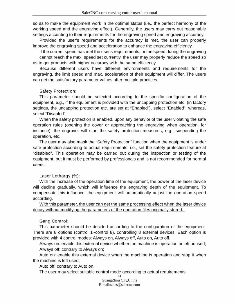
Click on the equipment information icon , the menu shown in Figure F7-2-2 will
appear:
All parameters of the equipment information are automatically set by the system, those
parameters are just descriptions and statistics of the status of the equipment and will
not
influence the normal operation of the equipment.
F7-2-2
1. System Information
Machine status: Current status of the equipment: operation, idle. (The user cannot
modify this parameter)
Accumulated copies: Total workload of the equipment. (The user cannot modify this
parameter)
2. Select Axis
Current Status: the status at current: operation, idle.
Current Coordinate Value (mm): location of the laser head on the selected axis, i.e., the
coordinate value corresponding to the mechanical origin.
Coordinate Value of Registration point (mm): the coordinate value of the registration
point on the axis, the user may modify this value to achieve precise locating.
Accumulated Travel (m): Total travel covered on the selected axis
SaleCNC.com carving cutter user’s manual
46
GuangZhou City,ChinaE-mail:[email protected]
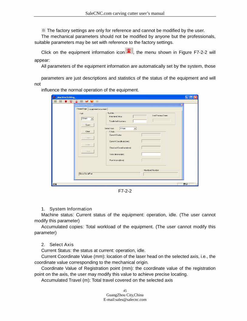
3. Motherboard Number: version number of the motherboard supporting the
current equipment, this number is provided by the system and cannot be modified
by the user.
F7-2-3
4. Equipment Inquiry: EMS memory space and files of the equipment
5. Download: downloading files into the equipment
6. Equipment File Management: here you can read the names of the equipment
files, delete files or start files, etc. .
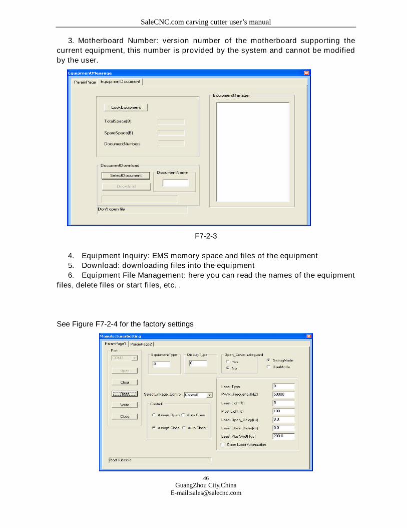
See Figure F7-2-4 for the factory settings
SaleCNC.com carving cutter user’s manual
47
GuangZhou City,ChinaE-mail:[email protected]
F7-2-4
Equipment Type:
Type of the machine used by the user. There are mainly general engravers and brand
engravers.
Display Block Type:
Display the type of the block according to the specific configuration of the machine.
Mode Fixed/Mode Optional:
If Mode Fixed is selected, the operation mode of the machine is not changeable and
can only be the mode set in factory.
If Mode Optional is selected, there are several modes for selection, the user may
switch between the modes and carry out parameter settings according to actual
requirements.
Debugging Mode/User Mode
Debugging Mode:
The mode used for debugging before leaving factory and cannot be used by the user.
When this mode is selected, the system will automatically copy the factory settings to the
user settings, therefore, the settings of the machine the user sees for the first time after the
machine leaves factory are the settings for the machine after debugging in factory.
User Mode:
The mode used when the user is operating the machine. The user may set the
parameters according to actual situation with reference of the factory settings. And the
parameters set by the user should govern after the settings, i.e., the PRI of user settings is
higher than that of the factory settings, the machine will adopt the user settings when
operating. But the parameter values set by the user cannot exceed that of the factory
settings, otherwise, the factory settings will govern.
Laser Device Type:
Select proper laser device type according to the laser device used by the machine.
PWM Frequency:
I.e., the light intensity frequency of the laser tube, this value differs according to
different types of the laser tubes, please consult the instructions for the laser tube for
details.
Min. Duty Ratio:
The min. duty ratio supported by the engraver.
Max. Duty Ratio:
The max. duty ratio supported by the engraver.
SaleCNC.com carving cutter user’s manual
48
GuangZhou City,ChinaE-mail:[email protected]
Laser On/Off Delay: the delay parameter set to avoid the uneven edges of the first
stroke and the last stroke when the laser is on or off.
Laser On Delay:
Because it takes a short period to start the laser, in order to make the light and the laser
head be started synchronously, the laser device is started before the laser head. I.e., the
Laser On Delay.
Laser Off Delay
Because it takes another period of time to shut off the laser after receiving the
instruction, in order to avoid excessive engraving, the laser is shut off in advance.
Min. Pulse Width:
The min. pulse width to be recognized by the laser device.
Decay Compensation On: as the laser tube has decay rate, this option is
recommended to be selected.
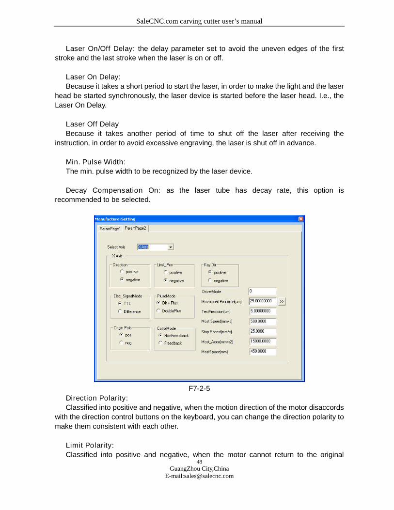
F7-2-5
Direction Polarity:
Classified into positive and negative, when the motion direction of the motor disaccords
with the direction control buttons on the keyboard, you can change the direction polarity to
make them consistent with each other.
Limit Polarity:
Classified into positive and negative, when the motor cannot return to the original
SaleCNC.com carving cutter user’s manual
49
GuangZhou City,ChinaE-mail:[email protected]
position, you can change the limit polarity to make it normal.
Button Polarity:
The buttons on the control panel correspond to directions of the motion of the axes, if it
moves to the right when you press the left, change the polarity.
Level Signal Mode:
There are TTL and differential modes, select the type according to the type of the motor
driver.
Pulse Mode:
The turning of the motor is driven by pulse. There are 2 modes of pulse sent by the
driver: Direction + Pulse, double-pulse; select the type according to the type of the motor
driver.
Origin Polarity:
The signal polarity when the machine returns to the origin, if the machine returns to the
origin when positive pole is selected, this origin polarity of the machine is positive,
otherwise, it’s negative.
Control Mode:
There are 2 control modes: open-loop and closed loop. This is set by the factory
according to the actual configuration of the machine, if the machine adopts the open-loop
control mode, this setting is open-loop; otherwise, it’s closed-loop.
Transmission Mode:
The transmission mode of the equipment is the configuration mode of the guide rail and
motor of the equipment, please consult the instructions of the machine to decide which
mode to adopt.
Max. Travel:
As either the bean or the guide rail has a fixed length, each machine has a max.
working breadth (i.e., working range), which limits the motion of the machine within
the max. working breadth and makes the trolley and the beam move within the
working range. The trolley and the beam will not hit the wall as there’s the limitation
of max. travel.
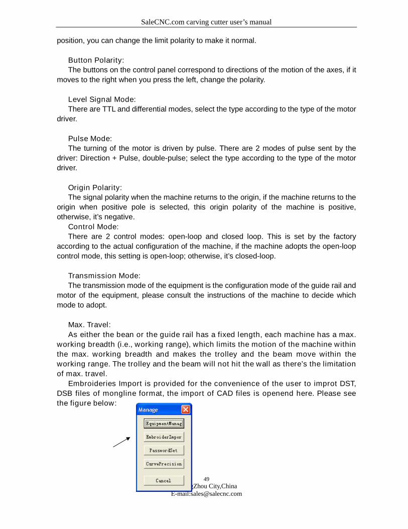
Embroideries Import is provided for the convenience of the user to improt DST,
DSB files of mongline format, the import of CAD files is openend here. Please see
the figure below:
SaleCNC.com carving cutter user’s manual
50
GuangZhou City,ChinaE-mail:[email protected]
Password is provided for unlock the limitations set by the factory.
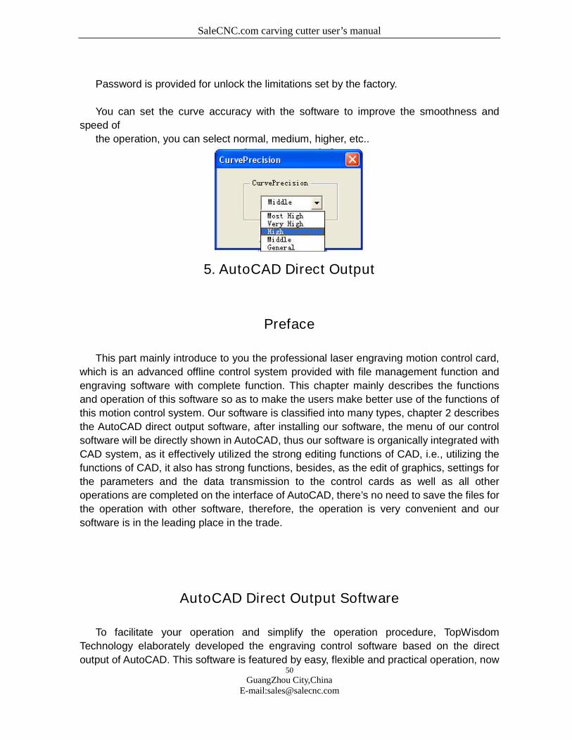
You can set the curve accuracy with the software to improve the smoothness and
speed of
the operation, you can select normal, medium, higher, etc..
5. AutoCAD Direct Output
Preface
This part mainly introduce to you the professional laser engraving motion control card,
which is an advanced offline control system provided with file management function and
engraving software with complete function. This chapter mainly describes the functions
and operation of this software so as to make the users make better use of the functions of
this motion control system. Our software is classified into many types, chapter 2 describes
the AutoCAD direct output software, after installing our software, the menu of our control
software will be directly shown in AutoCAD, thus our software is organically integrated with
CAD system, as it effectively utilized the strong editing functions of CAD, i.e., utilizing the
functions of CAD, it also has strong functions, besides, as the edit of graphics, settings for
the parameters and the data transmission to the control cards as well as all other
operations are completed on the interface of AutoCAD, there’s no need to save the files for
the operation with other software, therefore, the operation is very convenient and our
software is in the leading place in the trade.
AutoCAD Direct Output Software
To facilitate your operation and simplify the operation procedure, TopWisdom
Technology elaborately developed the engraving control software based on the direct
output of AutoCAD. This software is featured by easy, flexible and practical operation, now
SaleCNC.com carving cutter user’s manual
51
GuangZhou City,ChinaE-mail:[email protected]
we’re going to introduce to you the installation of operation of the software.
Operation platform: Windows98, Windows ME , Windows NT4, Windows 2000,
Windows XP, IE6.0 and Windows 2000 SP4 or above are required.
1.Install the AUTOCAD Direct Output System
Before installing this system, please install AutoCAD correctly.
Detailed installation of AutoCAD is passed over here. One point that we need to
emphasize is that when installing AUTOCAD, the VBA support must be installed,
otherwise this system cannot run.
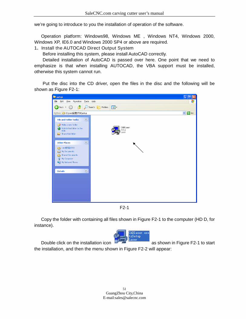
Put the disc into the CD driver, open the files in the disc and the following will be
shown as Figure F2-1:
F2-1
Copy the folder with containing all files shown in Figure F2-1 to the computer (HD D, for
instance).
Double click on the installation icon as shown in Figure F2-1 to start
the installation, and then the menu shown in Figure F2-2 will appear:
SaleCNC.com carving cutter user’s manual
52
GuangZhou City,ChinaE-mail:[email protected]
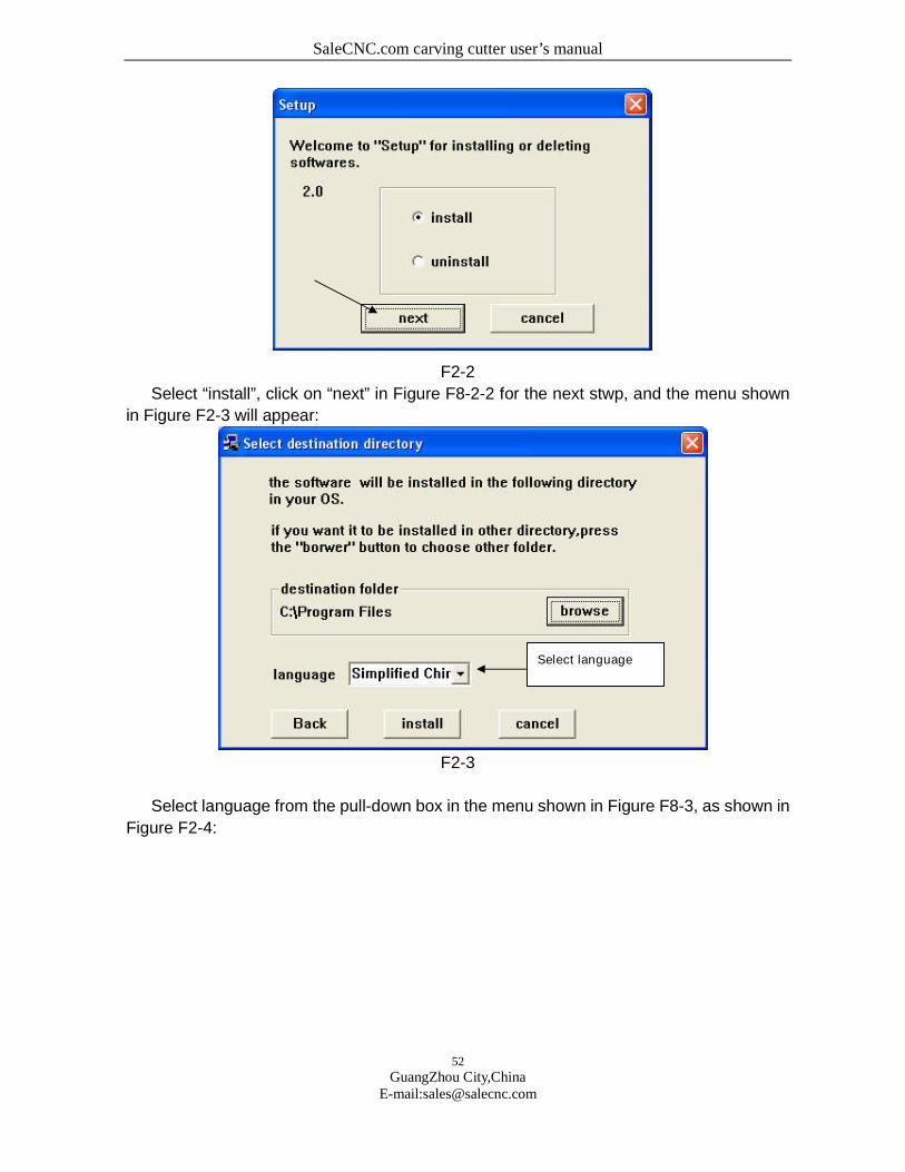
F2-2
Select “install”, click on “next” in Figure F8-2-2 for the next stwp, and the menu shown
in Figure F2-3 will appear:
F2-3
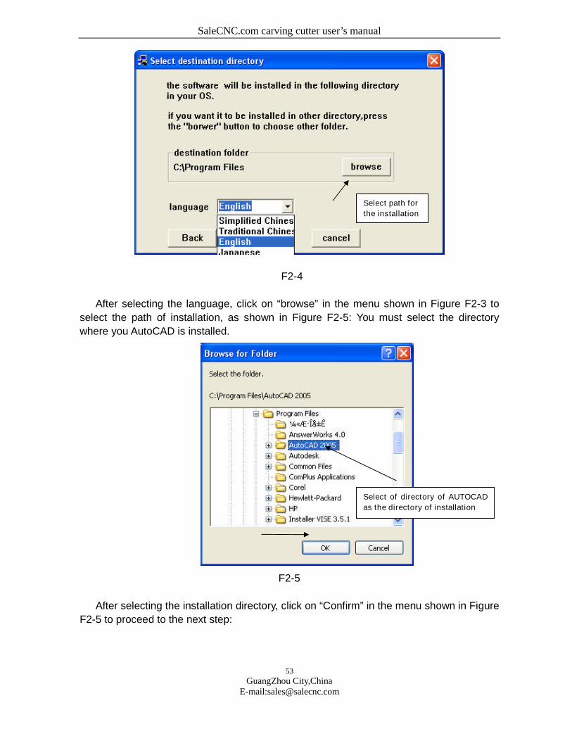
Select language from the pull-down box in the menu shown in Figure F8-3, as shown in
Figure F2-4:
Select language
SaleCNC.com carving cutter user’s manual
53
GuangZhou City,ChinaE-mail:[email protected]
F2-4
After selecting the language, click on “browse” in the menu shown in Figure F2-3 to
select the path of installation, as shown in Figure F2-5: You must select the directory
where you AutoCAD is installed.
F2-5
After selecting the installation directory, click on “Confirm” in the menu shown in Figure
F2-5 to proceed to the next step:
Select path for
the installation
Select of directory of AUTOCAD
as the directory of installation

SaleCNC.com carving cutter user’s manual
54
GuangZhou City,ChinaE-mail:[email protected]
F2-6
Select “Install” from the menu shown in Figure F2-6, and the system will be installed
autmatically, after the installation, the wondow shown in Figure F2-7 will appear:
F2-7
Click on "Conform” from the window shown in Figure F2-7 to end the installation.
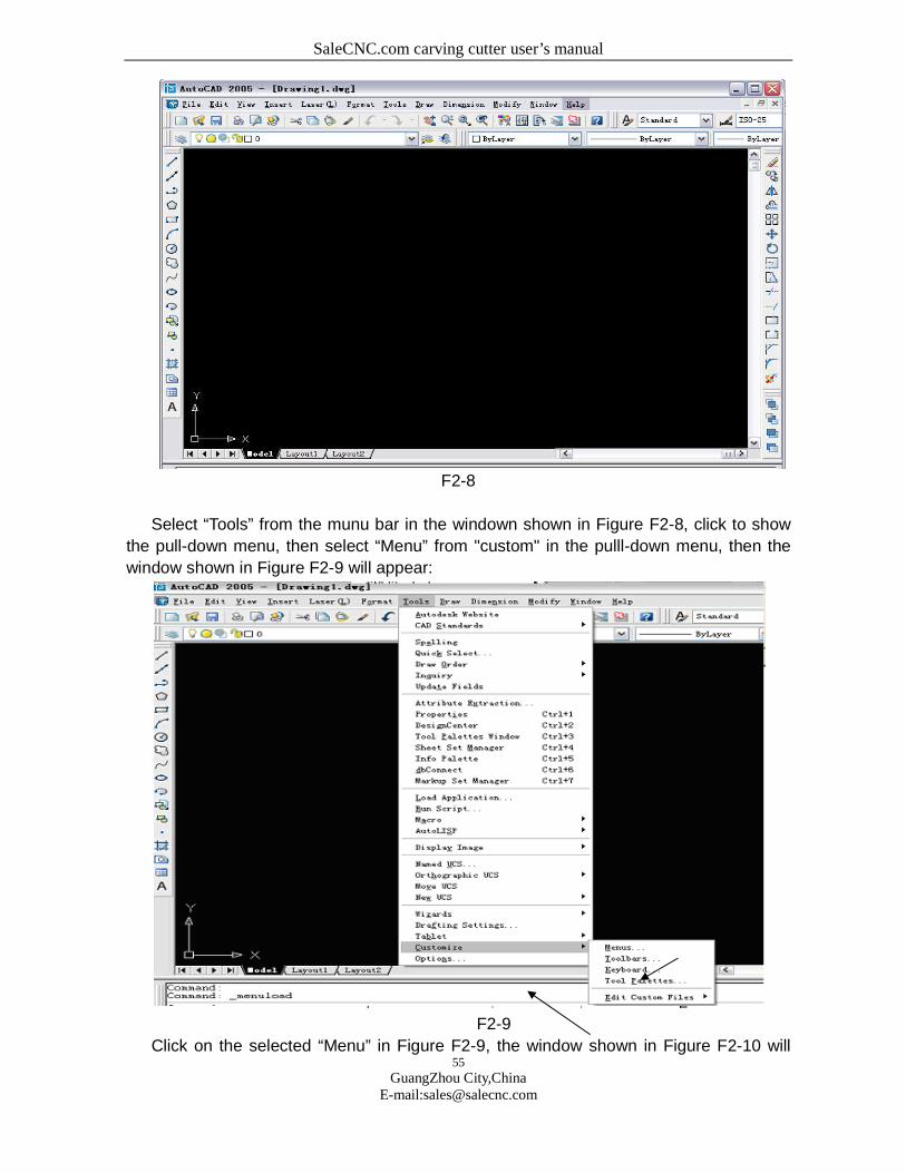
2.Configure the Engraving Program in the CAD Menu
After the installation, when you use the software for the first time, you need to make
configurationsfor the menu of engraving program, the operation menu is shown in Figure
F2-8:
SaleCNC.com carving cutter user’s manual
55
GuangZhou City,ChinaE-mail:[email protected]
F2-8
Select “Tools” from the munu bar in the windown shown in Figure F2-8, click to show
the pull-down menu, then select “Menu” from "custom" in the pulll-down menu, then the
window shown in Figure F2-9 will appear:
F2-9
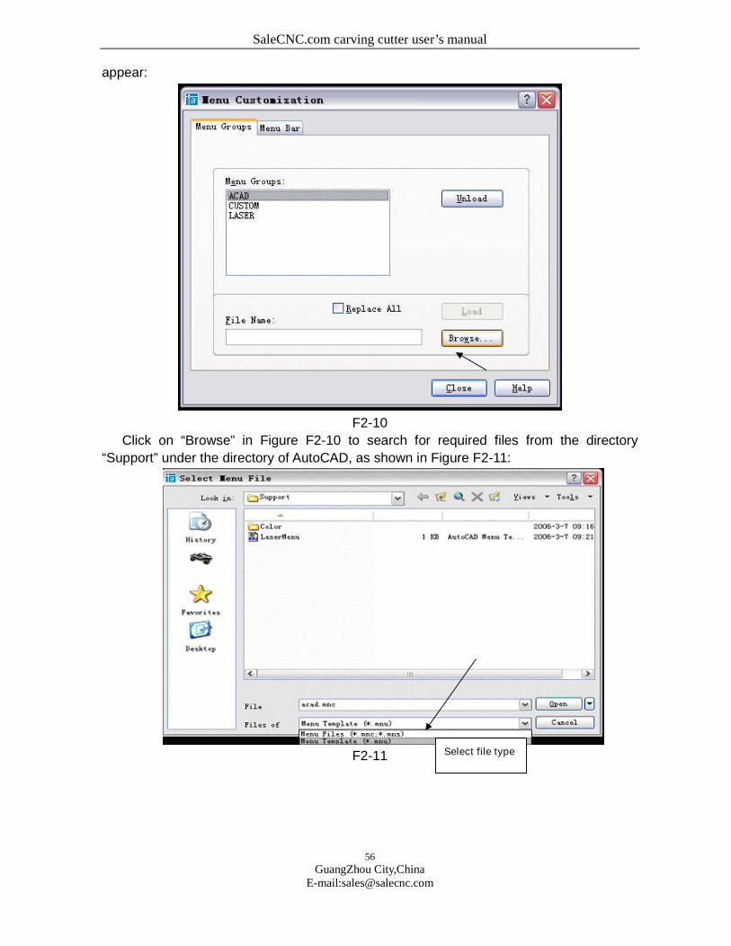
Click on the selected “Menu” in Figure F2-9, the window shown in Figure F2-10 will
SaleCNC.com carving cutter user’s manual
56
GuangZhou City,ChinaE-mail:[email protected]
appear:
F2-10
Click on “Browse” in Figure F2-10 to search for required files from the directory
“Support” under the directory of AutoCAD, as shown in Figure F2-11:
F2-11 Select file type
SaleCNC.com carving cutter user’s manual
57
GuangZhou City,ChinaE-mail:[email protected]
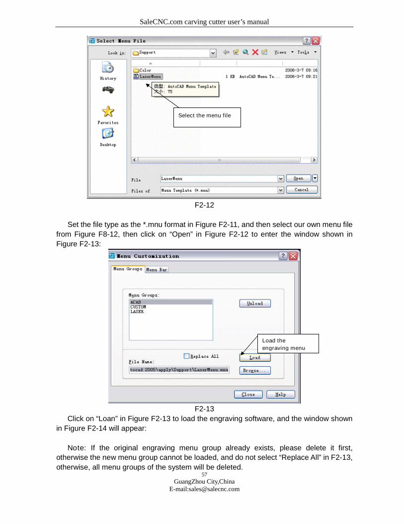
F2-12
Set the file type as the *.mnu format in Figure F2-11, and then select our own menu file
from Figure F8-12, then click on “Open” in Figure F2-12 to enter the window shown in
Figure F2-13:
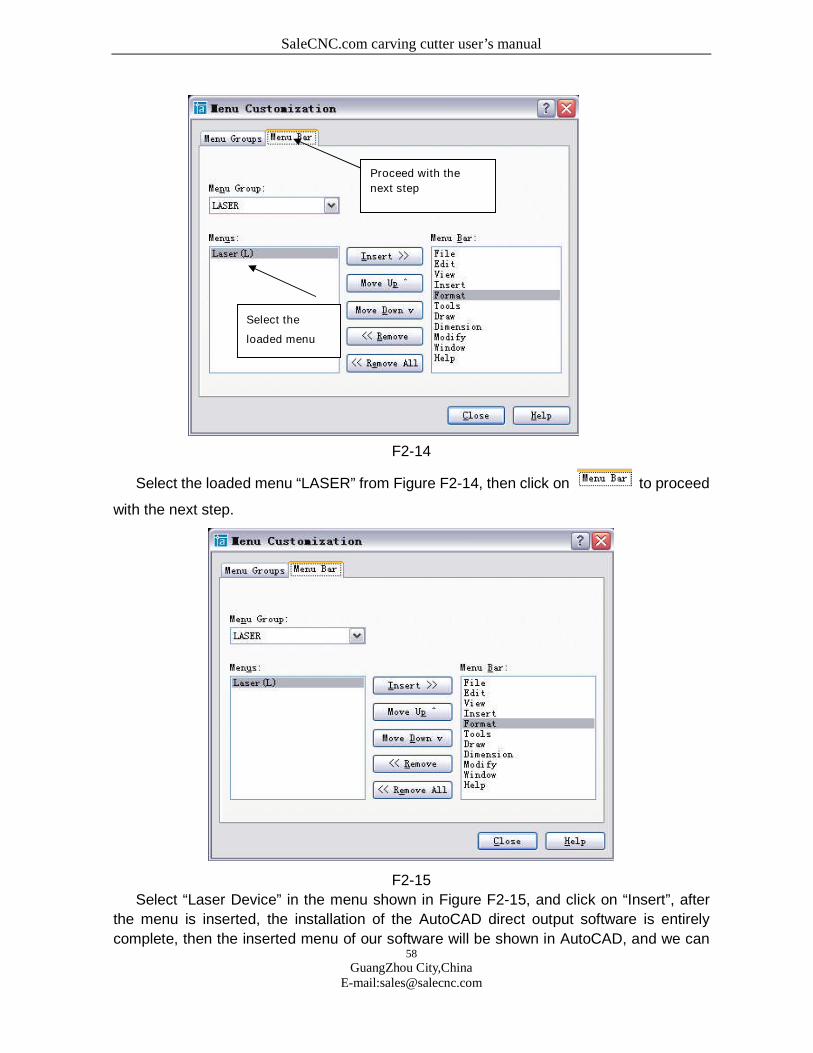
F2-13
Click on “Loan” in Figure F2-13 to load the engraving software, and the window shown
in Figure F2-14 will appear:
Note: If the original engraving menu group already exists, please delete it first,
otherwise the new menu group cannot be loaded, and do not select “Replace All” in F2-13,
otherwise, all menu groups of the system will be deleted.
Select the menu file
Load the
engraving menu
SaleCNC.com carving cutter user’s manual
58
GuangZhou City,ChinaE-mail:[email protected]
F2-14
Select the loaded menu “LASER” from Figure F2-14, then click on to proceed
with the next step.
F2-15
Select “Laser Device” in the menu shown in Figure F2-15, and click on “Insert”, after
the menu is inserted, the installation of the AutoCAD direct output software is entirely
complete, then the inserted menu of our software will be shown in AutoCAD, and we can
Select the
loaded menu
Proceed with the
next step
SaleCNC.com carving cutter user’s manual
59
GuangZhou City,ChinaE-mail:[email protected]
use it to directly export the graphics from CAD to our equipment in the future.
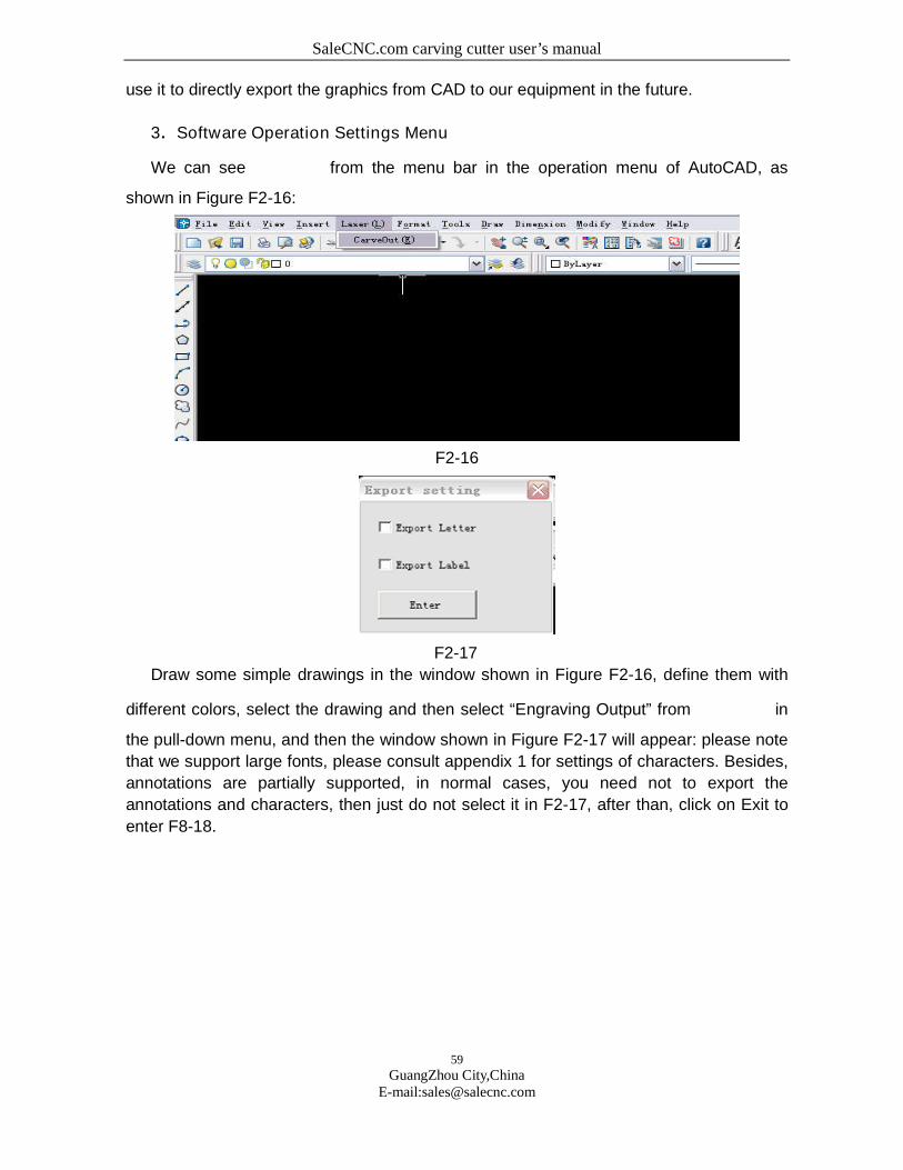
3.Software Operation Settings Menu
We can see from the menu bar in the operation menu of AutoCAD, as
shown in Figure F2-16:
F2-16
F2-17
Draw some simple drawings in the window shown in Figure F2-16, define them with
different colors, select the drawing and then select “Engraving Output” from in
the pull-down menu, and then the window shown in Figure F2-17 will appear: please note
that we support large fonts, please consult appendix 1 for settings of characters. Besides,
annotations are partially supported, in normal cases, you need not to export the
annotations and characters, then just do not select it in F2-17, after than, click on Exit to
enter F8-18.
SaleCNC.com carving cutter user’s manual
60
GuangZhou City,ChinaE-mail:[email protected]
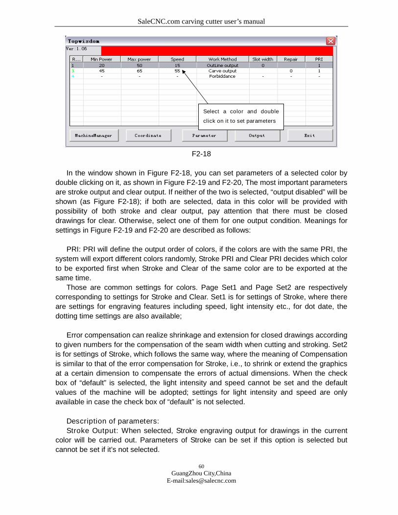
F2-18
In the window shown in Figure F2-18, you can set parameters of a selected color by
double clicking on it, as shown in Figure F2-19 and F2-20, The most important parameters
are stroke output and clear output. If neither of the two is selected, “output disabled” will be
shown (as Figure F2-18); if both are selected, data in this color will be provided with
possibility of both stroke and clear output, pay attention that there must be closed
drawings for clear. Otherwise, select one of them for one output condition. Meanings for
settings in Figure F2-19 and F2-20 are described as follows:
PRI: PRI will define the output order of colors, if the colors are with the same PRI, the
system will export different colors randomly, Stroke PRI and Clear PRI decides which color
to be exported first when Stroke and Clear of the same color are to be exported at the
same time.
Those are common settings for colors. Page Set1 and Page Set2 are respectively
corresponding to settings for Stroke and Clear. Set1 is for settings of Stroke, where there
are settings for engraving features including speed, light intensity etc., for dot date, the
dotting time settings are also available;
Error compensation can realize shrinkage and extension for closed drawings according
to given numbers for the compensation of the seam width when cutting and stroking. Set2
is for settings of Stroke, which follows the same way, where the meaning of Compensation
is similar to that of the error compensation for Stroke, i.e., to shrink or extend the graphics
at a certain dimension to compensate the errors of actual dimensions. When the check
box of “default” is selected, the light intensity and speed cannot be set and the default
values of the machine will be adopted; settings for light intensity and speed are only
available in case the check box of “default” is not selected.
Description of parameters:
Stroke Output: When selected, Stroke engraving output for drawings in the current
color will be carried out. Parameters of Stroke can be set if this option is selected but
cannot be set if it’s not selected.
Select a color and double
click on it to set parameters
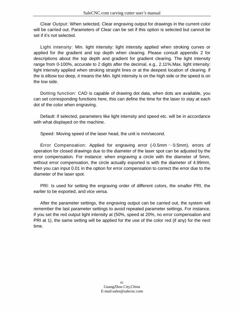
SaleCNC.com carving cutter user’s manual
61
GuangZhou City,ChinaE-mail:[email protected]
Clear Output: When selected, Clear engraving output for drawings in the current color
will be carried out. Parameters of Clear can be set if this option is selected but cannot be
set if it’s not selected.
Light intensity: Min. light intensity: light intensity applied when stroking curves or
applied for the gradient and top depth when clearing. Please consult appendix 2 for
descriptions about the top depth and gradient for gradient clearing. The light intensity
range from 0-100%, accurate to 2 digits after the decimal, e.g., 2.11%.Max. light intensity:
light intensity applied when stroking straight lines or at the deepest location of clearing. if
the is elbow too deep, it means the Min. light intensity is on the high side or the speed is on
the low side.
Dotting function: CAD is capable of drawing dot data, when dots are available, you
can set corresponding functions here, this can define the time for the laser to stay at each
dot of the color when engraving.
Default: if selected, parameters like light intensity and speed etc. will be in accordance
with what displayed on the machine.
Speed: Moving speed of the laser head, the unit is mm/second.
Error Compensation: Applied for engraving error (-0.5mm~ 0.5mm), errors of
operation for closed drawings due to the diameter of the laser spot can be adjusted by the
error compensation. For instance: when engraving a circle with the diameter of 5mm,
without error compensation, the circle actually exported is with the diameter of 4.99mm,
then you can input 0.01 in the option for error compensation to correct the error due to the
diameter of the laser spot.
PRI: Is used for setting the engraving order of different colors, the smaller PRI, the
earlier to be exported, and vice versa.
After the parameter settings, the engraving output can be carried out, the system will
remember the last parameter settings to avoid repeated parameter settings. For instance,
if you set the red output light intensity at (50%, speed at 20%, no error compensation and
PRI at 1), the same setting will be applied for the use of the color red (if any) for the next
time.
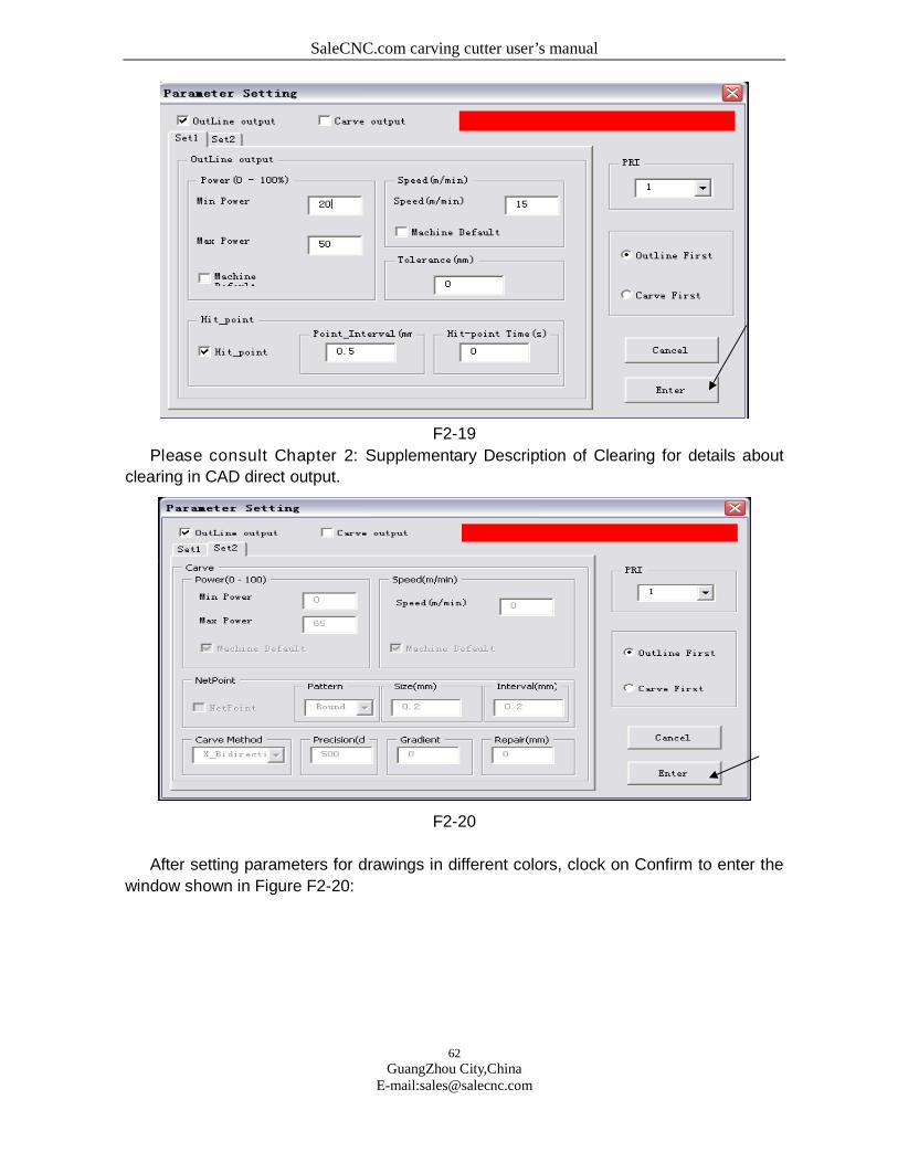
SaleCNC.com carving cutter user’s manual
62
GuangZhou City,ChinaE-mail:[email protected]
F2-19
Please consult Chapter 2: Supplementary Description of Clearing for details about
clearing in CAD direct output.
F2-20
After setting parameters for drawings in different colors, clock on Confirm to enter the
window shown in Figure F2-20:
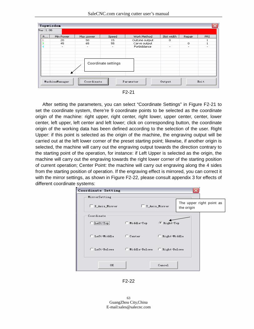
SaleCNC.com carving cutter user’s manual
63
GuangZhou City,ChinaE-mail:[email protected]
F2-21
After setting the parameters, you can select “Coordinate Settings” in Figure F2-21 to
set the coordinate system, there’re 9 coordinate points to be selected as the coordinate
origin of the machine: right upper, right center, right lower, upper center, center, lower
center, left upper, left center and left lower; click on corresponding button, the coordinate
origin of the working data has been defined according to the selection of the user. Right
Upper: if this point is selected as the origin of the machine, the engraving output will be
carried out at the left lower corner of the preset starting point; likewise, if another origin is
selected, the machine will carry out the engraving output towards the direction contrary to
the starting point of the operation, for instance: if Left Upper is selected as the origin, the
machine will carry out the engraving towards the right lower corner of the starting position
of current operation; Center Point: the machine will carry out engraving along the 4 sides
from the starting position of operation. If the engraving effect is mirrored, you can correct it
with the mirror settings, as shown in Figure F2-22, please consult appendix 3 for effects of
different coordinate systems:
F2-22
Coordinate settings
The upper right point as
the origin
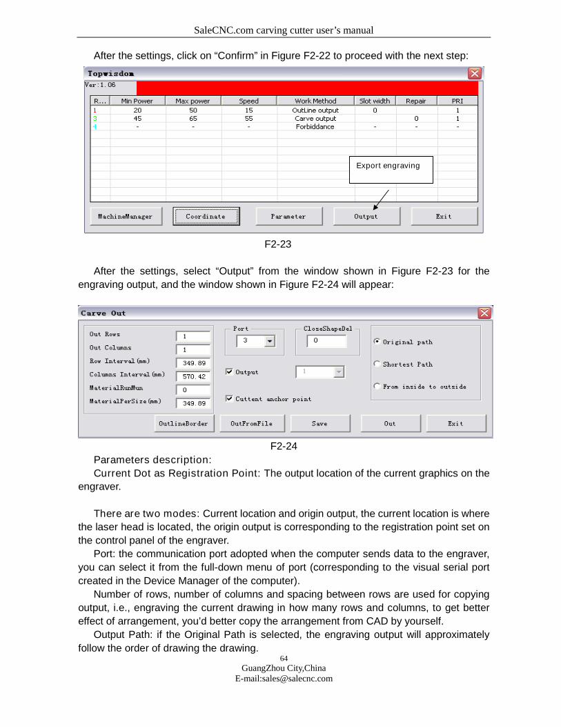
SaleCNC.com carving cutter user’s manual
64
GuangZhou City,ChinaE-mail:[email protected]
After the settings, click on “Confirm” in Figure F2-22 to proceed with the next step:
F2-23
After the settings, select “Output” from the window shown in Figure F2-23 for the
engraving output, and the window shown in Figure F2-24 will appear:
F2-24
Parameters description:
Current Dot as Registration Point: The output location of the current graphics on the
engraver.
There are two modes: Current location and origin output, the current location is where
the laser head is located, the origin output is corresponding to the registration point set on
the control panel of the engraver.
Port: the communication port adopted when the computer sends data to the engraver,
you can select it from the full-down menu of port (corresponding to the visual serial port
created in the Device Manager of the computer).
Number of rows, number of columns and spacing between rows are used for copying
output, i.e., engraving the current drawing in how many rows and columns, to get better
effect of arrangement, you’d better copy the arrangement from CAD by yourself.
Output Path: if the Original Path is selected, the engraving output will approximately
follow the order of drawing the drawing.
Export engraving

SaleCNC.com carving cutter user’s manual
65
GuangZhou City,ChinaE-mail:[email protected]
If Shortest Path is selected, drawings in the same color will be cut in the shortest path.
If Inside to Out side is selected, for closed drawings in the same color, the internal part
will be cut before the external part, which is necessary in some cases.
To a File: Export the current engraving data to a certain file, when necessary, export
the data to the equipment in “From a File” mode, and it is contrary to “From a File”, if you
need to select a certain file containing engraving data instead of exporting the current
drawing, you can adopt this operation mode.
Output Engraving: Directly export the graphics file opened currently in CAD to the
equipment by engraving.
Description: Graphics exported from the engraving equipment is only related to the
size of the graphics in CAD instead of the original position of it in the drawing area of CAD.
Appendixes
1. Supports for AUTOCAD Direct Output Annotation Text
Text and annotations in CAD system are normally exported as auxiliary information,
therefore, in usual cases, you need not select text and annotations in the window shown in
Figure F2-17. However, in special cases, e.g., the user needs to engrave the text in the
graphics, and even the annotations, for output, you can select corresponding options in
the window shown in Figure F2-17.
First, you’d like to announce that we do not support text and annotations to a fractional,
however, there are some limitations, for example, we support 5, 6 types of large fonts,
settings for large fonts are as follows: first enter the menu shown in Figure FL-1, select
Font in the “Format” menu.
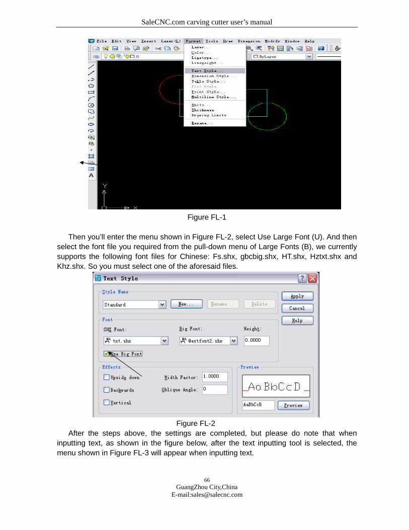
SaleCNC.com carving cutter user’s manual
66
GuangZhou City,ChinaE-mail:[email protected]
Figure FL-1
Then you’ll enter the menu shown in Figure FL-2, select Use Large Font (U). And then
select the font file you required from the pull-down menu of Large Fonts (B), we currently
supports the following font files for Chinese: Fs.shx, gbcbig.shx, HT.shx, Hztxt.shx and
Khz.shx. So you must select one of the aforesaid files.
Figure FL-2
After the steps above, the settings are completed, but please do note that when
inputting text, as shown in the figure below, after the text inputting tool is selected, the
menu shown in Figure FL-3 will appear when inputting text.

SaleCNC.com carving cutter user’s manual
67
GuangZhou City,ChinaE-mail:[email protected]
Figure FL-3
Then you just let it adopt the default font shown in Figure FL-3, do not select the
English fonts or Song typeface or boldface etc. from the pull-down menu, for those may
not be supported by our software temporarily. After this, our software can support the
engraving output of text in CAD interface.
If you selected Annotation Support in Figure F2-17, the engraving output of annotations
will be supported, but you must note that an annotation is usually provided with an arrow,
while we ignore the arrow head and left only the line section.
2. Clearing Gradient Sketch Map:
Figure FL-4
3. Data Coordinate System
Figure FL-5
In Figure FL-5, the default setting is the Right Upper, which is used in usual cases,
other settings will be used to special applications, if we take the current location of the
laser head as the initial registration point of current engraving, the figure below shows the
position of the exported drawing relative to the laser head at the initial position, assuming
the crossing to be the laser head at the initial position.
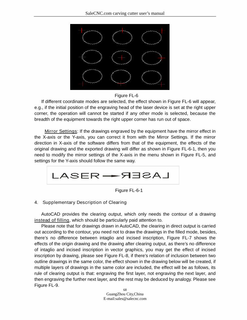
SaleCNC.com carving cutter user’s manual
68
GuangZhou City,ChinaE-mail:[email protected]
Figure FL-6
If different coordinate modes are selected, the effect shown in Figure FL-6 will appear,
e.g., if the initial position of the engraving head of the laser device is set at the right upper
corner, the operation will cannot be started if any other mode is selected, because the
breadth of the equipment towards the right upper corner has run out of space.
Mirror Settings: If the drawings engraved by the equipment have the mirror effect in
the X-axis or the Y-axis, you can correct it from with the Mirror Settings. If the mirror
direction in X-axis of the software differs from that of the equipment, the effects of the
original drawing and the exported drawing will differ as shown in Figure FL-6-1, then you
need to modify the mirror settings of the X-axis in the menu shown in Figure FL-5, and
settings for the Y-axis should follow the same way.
Figure FL-6-1
4. Supplementary Description of Clearing
AutoCAD provides the clearing output, which only needs the contour of a drawing
instead of filling, which should be particularly paid attention to.
Please note that for drawings drawn in AutoCAD, the clearing in direct output is carried
out according to the contour, you need not to draw the drawings in the filled mode, besides,
there’s no difference between intaglio and incised inscription, Figure FL-7 shows the
effects of the origin drawing and the drawing after clearing output, as there’s no difference
of intaglio and incised inscription in vector graphics, you may get the effect of incised
inscription by drawing, please see Figure FL-8, if there’s relation of inclusion between two
outline drawings in the same color, the effect shown in the drawing below will be created, if
multiple layers of drawings in the same color are included, the effect will be as follows, its
rule of clearing output is that: engraving the first layer, not engraving the next layer, and
then engraving the further next layer, and the rest may be deduced by analogy. Please see
Figure FL-9.
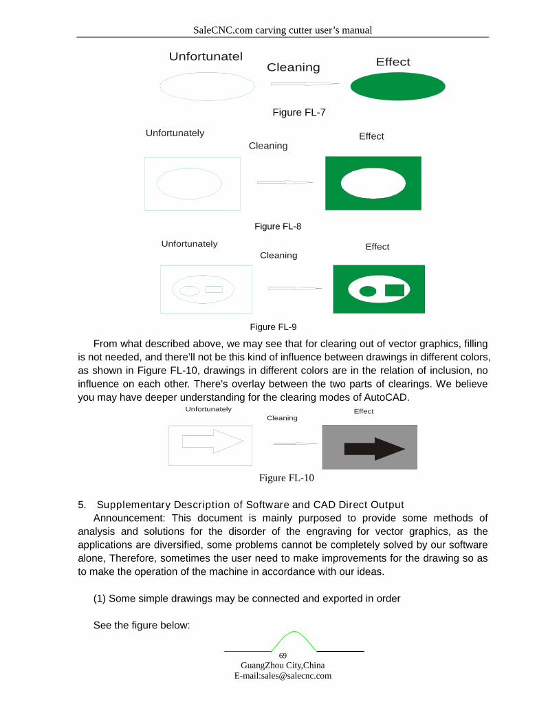
SaleCNC.com carving cutter user’s manual
69
GuangZhou City,ChinaE-mail:[email protected]
CleaningUnfortunatel Effect
Figure FL-7
Cleaning
Unfortunately Effect
Figure FL-8
Cleaning
Unfortunately Effect
Figure FL-9
From what described above, we may see that for clearing out of vector graphics, filling
is not needed, and there’ll not be this kind of influence between drawings in different colors,
as shown in Figure FL-10, drawings in different colors are in the relation of inclusion, no
influence on each other. There’s overlay between the two parts of clearings. We believe
you may have deeper understanding for the clearing modes of AutoCAD.
Cleaning
Unfortunately Effect
Figure FL-10
5. Supplementary Description of Software and CAD Direct Output
Announcement: This document is mainly purposed to provide some methods of
analysis and solutions for the disorder of the engraving for vector graphics, as the
applications are diversified, some problems cannot be completely solved by our software
alone, Therefore, sometimes the user need to make improvements for the drawing so as
to make the operation of the machine in accordance with our ideas.
(1) Some simple drawings may be connected and exported in order
See the figure below:
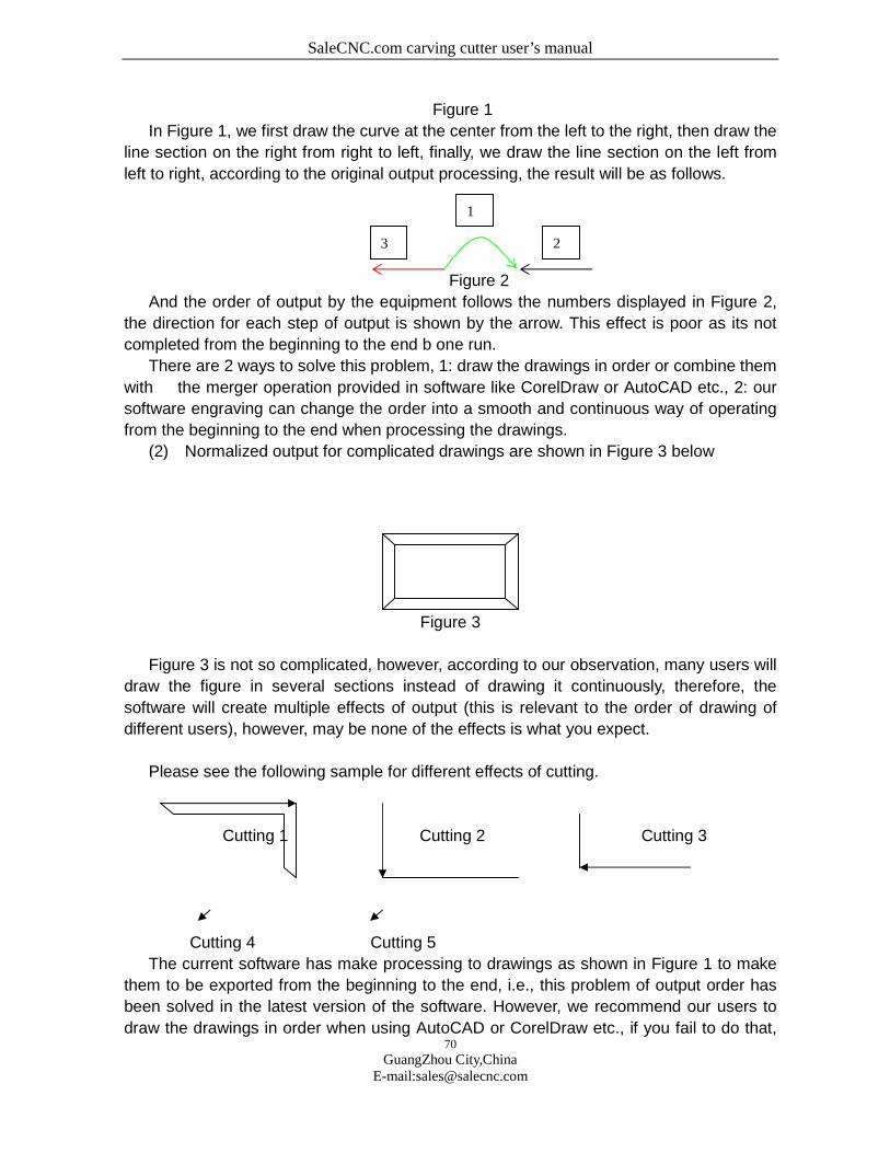
SaleCNC.com carving cutter user’s manual
70
GuangZhou City,ChinaE-mail:[email protected]
Figure 1
In Figure 1, we first draw the curve at the center from the left to the right, then draw the
line section on the right from right to left, finally, we draw the line section on the left from
left to right, according to the original output processing, the result will be as follows.
Figure 2
And the order of output by the equipment follows the numbers displayed in Figure 2,
the direction for each step of output is shown by the arrow. This effect is poor as its not
completed from the beginning to the end b one run.
There are 2 ways to solve this problem, 1: draw the drawings in order or combine them
with the merger operation provided in software like CorelDraw or AutoCAD etc., 2: our
software engraving can change the order into a smooth and continuous way of operating
from the beginning to the end when processing the drawings.
(2) Normalized output for complicated drawings are shown in Figure 3 below
Figure 3
Figure 3 is not so complicated, however, according to our observation, many users will
draw the figure in several sections instead of drawing it continuously, therefore, the
software will create multiple effects of output (this is relevant to the order of drawing of
different users), however, may be none of the effects is what you expect.
Please see the following sample for different effects of cutting.
Cutting 1 Cutting 2 Cutting 3
Cutting 4 Cutting 5
The current software has make processing to drawings as shown in Figure 1 to make
them to be exported from the beginning to the end, i.e., this problem of output order has
been solved in the latest version of the software. However, we recommend our users to
draw the drawings in order when using AutoCAD or CorelDraw etc., if you fail to do that,
3
1
2
SaleCNC.com carving cutter user’s manual
71
GuangZhou City,ChinaE-mail:[email protected]
you can combine them together with the merger operation provided in the aforesaid
software, which may provide higher fault tolerance.
As you can see in the drawings above, it totally takes 5 times to cut the entire drawing,
and the procedure is disordered. The effect is not expected, seeing from the stroking in the
drawings above, each stroke reaches the end and stops till there’s no connected line
section, but it is hard to choice the path in this way, and there’s also great randomness,
therefore, the entire drawing is divided into several parts. There’s little software, currently,
is provided with the capacity to manage the problems as a whole like human being, for
instance, cutting the external rectangle before the internal part etc.. Therefore, we must
pay attention to this kind of drawing when drawing, e.g., if you want to cut the two
rectangles along the 4 sides, you must combine the separate line sections of the
rectangles together with software, thus the disordered engraving will be avoided and a
relatively neat path will be achieved. Many users just patch up the drawings stroke by
stroke in irregular order, therefore, multiple types of stroking will be created for a drawing
as shown in Figure 1, which is actually very simple, while in fact, there are many drawings
much more complicated than this one, one joint may be connected with many line sections,
and the stroking will be more disordered, so it’s hard to arrange the order effectively by out
software alone, and you must solve the problem form the beginning, the method of
drawing.
(3) Disordered output for single lines without joint or crossing
Figure 4
Figure 4 seems to the same to Figure 1 at first view; however, the engraving is
disordered, why? Let’s amplify the drawing and you can see that there’s no joint between
the line sections, so the order cannot the arranged. Therefore, when drawing, pay
attention that the joints must be closed.
(4) No display when opening the drawing in a 3rd party engraving software, or
run into a wall when using CAD for direct output.
For example, you draw a drawing in CAD, which looks normal, while it cannot be
displayed in a 3rd party engraving software, or run into a wall when exported to the
equipment. Why? This is normally caused by a small drawing or dot far away from the
drawing, which is not what the user expects to process but is just drawn by mistake, this
makes the whole drawing to be so large and cannot be seen when opened in another
software after zooming out, and the breadth of output will be far exceeding the operation
breadth of the equipment, which will also cause problems.
(5) Part of the drawings of CAD direct output or in DXF files cannot be displayed
and processed
SaleCNC.com carving cutter user’s manual
72
GuangZhou City,ChinaE-mail:[email protected]
AutoCAD2005 is newly provided with region tools and table tools, parts of a closed
drawing can be processed into the drawing of a region via the region tools on the left. Then
the software cannot recognize and process it, so pay attention that there should not be any
region drawing when drawing, if there are some, they should be redrawn by line sections
or curves or be broken up with breakup operation. Tables drawn with the table tools should
follow the same way, they can be normally exported after being broken up, those are all
new features after AutoCAD2005.
6.Buttons of the Carving/ Cutting Electronic Control System
1. “Emergency” button: in any cases, pressing this button will enter into reset and turnto the defined “resetting point”.
2. “Menu” button: to be used under offline, in the way of collecting files from the RAMand running independent of PC.
3. “Exit” button: custom button for operation cancel.
4. “Point operation” button: for test of optical circuit adjustment; pressing once forlighting once.
5. “Confirm” button: custom button for confirmation to current operation.
6. “Speed” button: pressing any of “←”, “→”, “↑”, and “↓” to change the work speedwhen machine offline, where “←” or “→” is to add or reduce 10 units each time, and “↑” or“↓”is to add or reduce 1 unit each time. Adjustable within 0~100.
7. “Minimal luminous intensity” button: the minimal laser intensity of the machine output,adjustable by “←”, “→”, “↑”, or “↓”. Adjustable within 0~100.
8. “Maximal luminous intensity” button: the maximal laser intensity responded by themachine, adjustable by “←”, “→”, “↑”, or “↓”. Adjustable within 0~100.
9. “Repeat” button: repeat the previous operation, either staying or moving. Pressingonce for repeating once.
10. “Start/ pause” button: pause or continue machine service. Pressing once aftermoving X or Y axis without pressing the “Position” button may continue executing theremain commands at the original point.
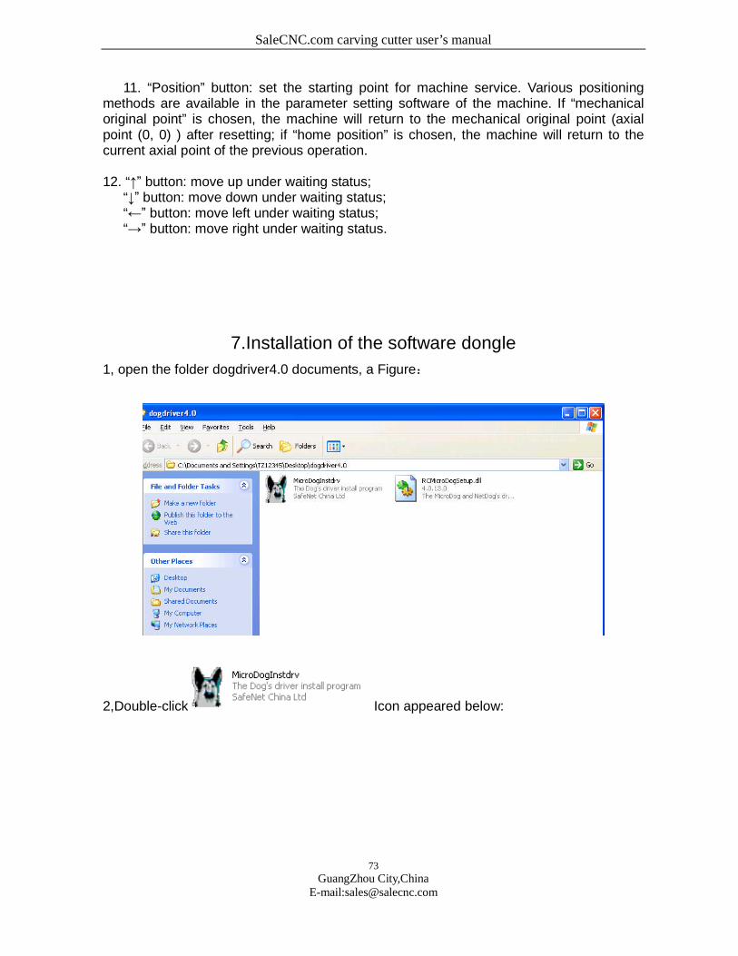
SaleCNC.com carving cutter user’s manual
73
GuangZhou City,ChinaE-mail:[email protected]
11. “Position” button: set the starting point for machine service. Various positioningmethods are available in the parameter setting software of the machine. If “mechanicaloriginal point” is chosen, the machine will return to the mechanical original point (axialpoint (0, 0) ) after resetting; if “home position” is chosen, the machine will return to thecurrent axial point of the previous operation.
12. “↑” button: move up under waiting status;“↓” button: move down under waiting status;“←” button: move left under waiting status;“→” button: move right under waiting status.
7.Installation of the software dongle
1, open the folder dogdriver4.0 documents, a Figure:
2,Double-click Icon appeared below:
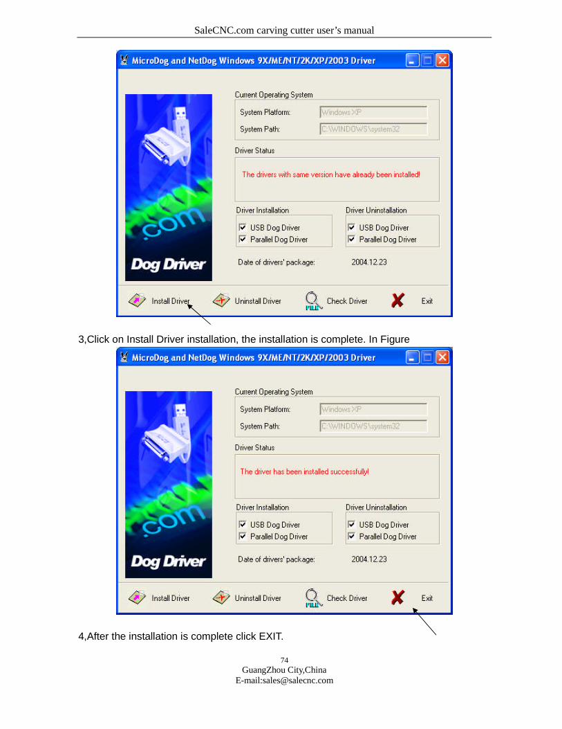
SaleCNC.com carving cutter user’s manual
74
GuangZhou City,ChinaE-mail:[email protected]
3,Click on Install Driver installation, the installation is complete. In Figure
4,After the installation is complete click EXIT.
SaleCNC.com carving cutter user’s manual
75
GuangZhou City,ChinaE-mail:[email protected]
8.Installing and debugging engraving system
One Install mainboard driver
This kind of mainboard uses the USB port and the computer connection, transmits the
data. Before the it useing, must install the driver
Method of Installing:
Starts the computer first, turns on the carving machine power, then connects with the
USB ties the computer and the mainboard, by now on the computer screen could appear
"discovers the new hardware... ... " etc, sees photo F2-18:
F2-18
Please put the application which one is allocated stochastically into CD-ROM, a few
minutes later it will appear like the F2-19 dialog box:
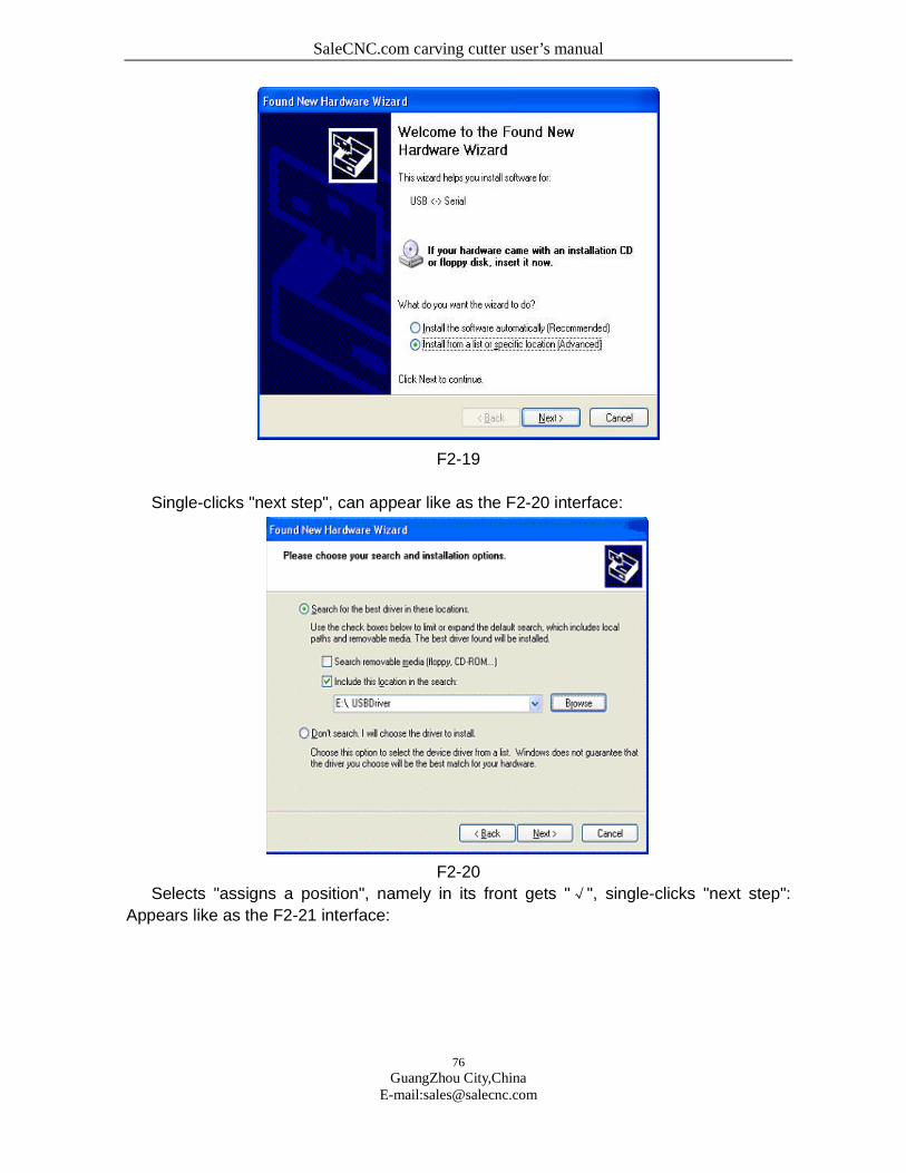
SaleCNC.com carving cutter user’s manual
76
GuangZhou City,ChinaE-mail:[email protected]
F2-19
Single-clicks "next step", can appear like as the F2-20 interface:
F2-20
Selects "assigns a position", namely in its front gets "√", single-clicks "next step":
Appears like as the F2-21 interface:
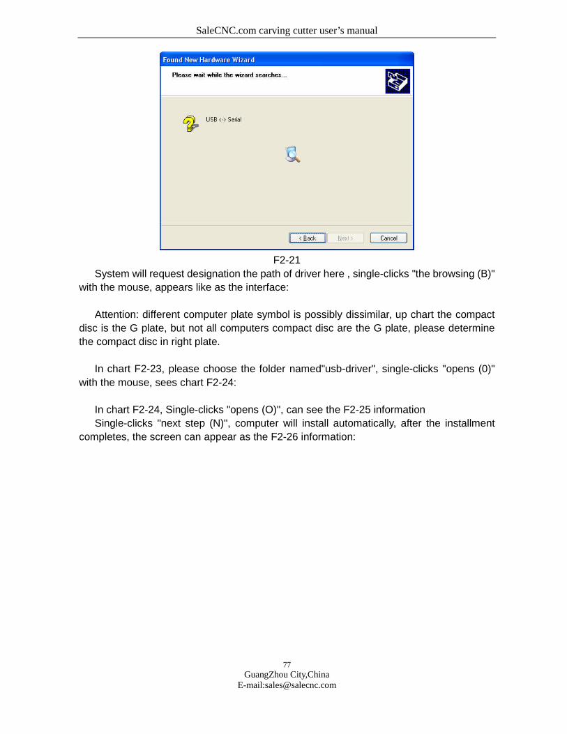
SaleCNC.com carving cutter user’s manual
77
GuangZhou City,ChinaE-mail:[email protected]
F2-21
System will request designation the path of driver here , single-clicks "the browsing (B)"
with the mouse, appears like as the interface:
Attention: different computer plate symbol is possibly dissimilar, up chart the compact
disc is the G plate, but not all computers compact disc are the G plate, please determine
the compact disc in right plate.
In chart F2-23, please choose the folder named"usb-driver", single-clicks "opens (0)"
with the mouse, sees chart F2-24:
In chart F2-24, Single-clicks "opens (O)", can see the F2-25 information
Single-clicks "next step (N)", computer will install automatically, after the installment
completes, the screen can appear as the F2-26 information:

SaleCNC.com carving cutter user’s manual
78
GuangZhou City,ChinaE-mail:[email protected]
F2-23
Single-clicks "finish" button, finished the equipment driver installing. Restarts the
computer and put the mouse on "my computer" to single-click the right key, find out "the
attribute", choose "the hardware" in "equipment manager" ,examine "the port (com and
plt)", then you can see the driver information "usb serial port com3", indicated the carving
machine use the output port is COM3, sees interface F2-27:
F2-24
SaleCNC.com carving cutter user’s manual
79
GuangZhou City,ChinaE-mail:[email protected]
Above chart "COM3" is transmission data port from computer to the carving machine,
when carving outputting, software must choose this port similarly, these two ports must be
consistent, otherwise is unable to output.
Usual time if has already installed the driver, does not need to install again, but if
appears cannot find the string mouth, maybe cause by other reasons. If you has carried on
the above driver installment many times as some kind of reason,then possibility to be
able to find COM5, COM6, now the computer possibly was unable to find the correct
outputting port, carved cannot carry on. If this kind of situation happened,please carry out
ftdiunin.Exe unloading procedure inside driver folder, and then carries out reinstalls again.
9.Maintenance and maintenance
Maintenance, maintenance, not only may cause your work work to bemore effective,
may promote the machine the work security andlengthens the equipment the service
life, the guarantee processingprecision is very important.
1:The engine bed bed body, the laser power source, the computer powersource must
good earth, earths will not be good can reduce stirs upthe fluorescent tube the
life, when the high-pressured electricdischarge can damage the control circuit, even
will threaten thesafety.
2:The bed essential maintenance is clean, specially three straight linesguide rails,
must frequently scour, prevented the dust causes themachine guide rail to abrade
the aging. And spreads lubricating oil toguard against rusts, affects the processing
precision.
3:The work supports the platform, (specially is cuts) after the longtime can glue
on the organic matter. Meets the light illuminationpossibly to be able to brave the
smoke, even burns, should regularlyeliminate.

SaleCNC.com carving cutter user’s manual
80
GuangZhou City,ChinaE-mail:[email protected]
4:Pays attention to in the bed a row of gusty area not to be possible tostop up,
maintains as necessary except the cover unimpededly.
5:The cooling water must frequently replace, maintenance clean, every 3- 5 days
replace time for are suitable. The suggestion use pure water,and the attention water
volume cannot be smaller than 50 litres. Andcertainly wants the immerse water pump,
the water temperature not tobe able to surpass 40 ℃.
6:Reflects the lens and the lens maintenance
(1)Reflector after long time can pollute, reduces the index ofreflection, must
maintain cleanly, its maintenance period regards theprocessing material quality
characteristic and the operating timelength decides. Please use the absorbent cotton
festooned club tomoisten the special-purpose lens cleanser gently to clean.
(2)The lens lens undersurface possibly can work the volatile matterpollution,
on sometimes the surface also can have falls the dust. Whendiscovery not only, also
must promptly scour.
Focuses the mirror clean method:
Ⅰ:Wrenches or twist open fastens the tube the screw with to fasten theair faucet
the screw, carefully takes down the tube (to for detailssee focuses mirror structure
drawing)。
Ⅱ:With washes the earlobe to blow the lens surface floating dust.
Ⅲ:Moistens the special-purpose lens cleanser within with the absorbentcotton
festooned club gently to clean, wants to clean to theextroverted identical direction,
every time scratches a time, needs toreplace the absorbent cotton festooned club,
removes until thecontamination.
** Warning **
Do not use the non- lens special-purpose cleanser, otherwise cancorrode the
lens.
Do not use the compressed air directly to spurt the lens.
Cleanly maintains in front of the lens first clear to wash the hands.
Please directly do not spray any liquid to the lens.

SaleCNC.com carving cutter user’s manual
81
GuangZhou City,ChinaE-mail:[email protected]
Does not allow back and forth to scratch, may not be incisivescratches the
lens surface.
** Attention **
Please do not blow the bad lens surface coating level! The
overstrainclean movement can damage the lens and reduce the lens the
servicelife! Also do not have to the hand to touch the lens, be
pleasecareful! May let long-time which your lens uses!
10.Equipment frequently asked questions faq and solution
Phenomeno
n
Possible reason Solution
The laser
machine
cannot carve
1: Whether the power source is
AC220V50HZ
2: Whether electrifies
3:Whether opens switch
4: The software output port
establishes whethercorrect
5: Whether transmits the correct
data to give the carvingmachine
6: The opening machine order isn't
whether correct
1: Inserts the carving machine
power source, opens switch
2: Transmitsthe correct
document format
The laser
1: The operating system has the virus
or damages
2: Laser carvingsoftware is not
normal
1: Reinstalls the operating
system, looks up kills viral
2: Reinstallslaser carving
software
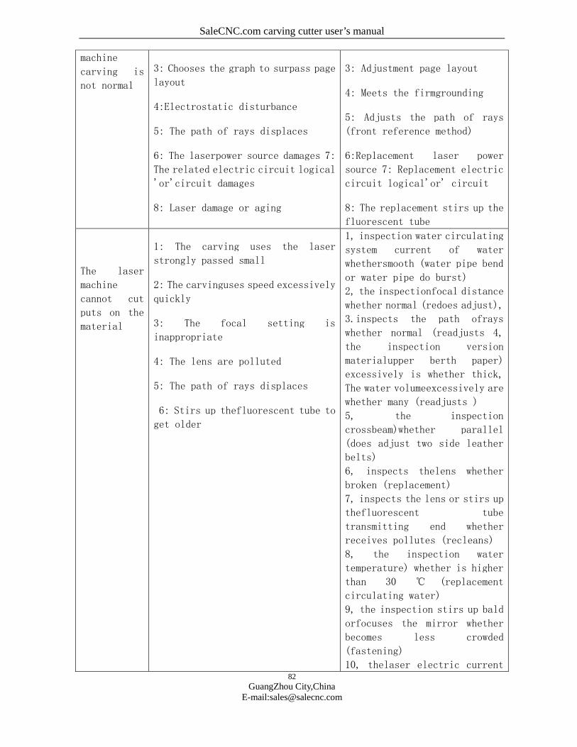
SaleCNC.com carving cutter user’s manual
82
GuangZhou City,ChinaE-mail:[email protected]
machine
carving is
not normal
3: Chooses the graph to surpass page
layout
4:Electrostatic disturbance
5: The path of rays displaces
6: The laserpower source damages 7:
The related electric circuit logical
'or'circuit damages
8: Laser damage or aging
3: Adjustment page layout
4: Meets the firmgrounding
5: Adjusts the path of rays
(front reference method)
6:Replacement laser power
source 7: Replacement electric
circuit logical'or' circuit
8: The replacement stirs up the
fluorescent tube
The laser
machine
cannot cut
puts on the
material
1: The carving uses the laser
strongly passed small
2: The carvinguses speed excessively
quickly
3: The focal setting is
inappropriate
4: The lens are polluted
5: The path of rays displaces
6: Stirs up thefluorescent tube to
get older
1, inspection water circulating
system current of water
whethersmooth (water pipe bend
or water pipe do burst)
2, the inspectionfocal distance
whether normal (redoes adjust),
3.inspects the path ofrays
whether normal (readjusts 4,
the inspection version
materialupper berth paper)
excessively is whether thick,
The water volumeexcessively are
whether many (readjusts )
5, the inspection
crossbeam)whether parallel
(does adjust two side leather
belts)
6, inspects thelens whether
broken (replacement)
7, inspects the lens or stirs up
thefluorescent tube
transmitting end whether
receives pollutes (recleans)
8, the inspection water
temperature) whether is higher
than 30 ℃ (replacement
circulating water)
9, the inspection stirs up bald
orfocuses the mirror whether
becomes less crowded
(fastening)
10, thelaser electric current
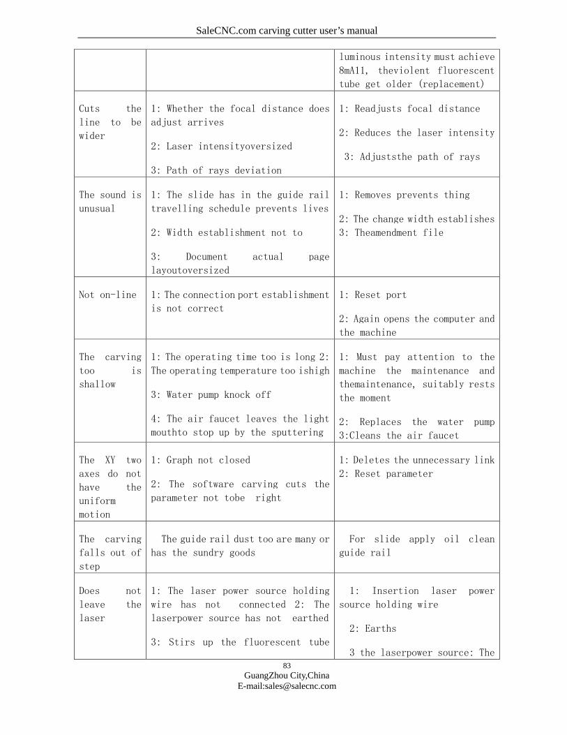
SaleCNC.com carving cutter user’s manual
83
GuangZhou City,ChinaE-mail:[email protected]
luminous intensity must achieve
8mA11, theviolent fluorescent
tube get older (replacement)
Cuts the
line to be
wider
1: Whether the focal distance does
adjust arrives
2: Laser intensityoversized
3: Path of rays deviation
1: Readjusts focal distance
2: Reduces the laser intensity
3: Adjuststhe path of rays
The sound is
unusual
1: The slide has in the guide rail
travelling schedule prevents lives
2: Width establishment not to
3: Document actual page
layoutoversized
1: Removes prevents thing
2: The change width establishes
3: Theamendment file
Not on-line 1: The connection port establishment
is not correct
1: Reset port
2: Again opens the computer and
the machine
The carving
too is
shallow
1: The operating time too is long 2:
The operating temperature too ishigh
3: Water pump knock off
4: The air faucet leaves the light
mouthto stop up by the sputtering
1: Must pay attention to the
machine the maintenance and
themaintenance, suitably rests
the moment
2: Replaces the water pump
3:Cleans the air faucet
The XY two
axes do not
have the
uniform
motion
1: Graph not closed
2: The software carving cuts the
parameter not tobe right
1: Deletes the unnecessary link
2: Reset parameter
The carving
falls out of
step
The guide rail dust too are many or
has the sundry goods
For slide apply oil clean
guide rail
Does not
leave the
laser
1: The laser power source holding
wire has not connected 2: The
laserpower source has not earthed
3: Stirs up the fluorescent tube
1: Insertion laser power
source holding wire
2: Earths
3 the laserpower source: The
SaleCNC.com carving cutter user’s manual
84
GuangZhou City,ChinaE-mail:[email protected]
twowiring not to weld inspection stirs up the
fluorescent tube two wiring
★ Attention: Above has the problem to need the specialized
operator toprocess, the operator could not solve, please
with the dealer or thefactory relation, was sure not
arbitrarily to process!
Related Documents


