2009:091 MASTER'S THESIS Laser Beam Welding of Carbide Free Bainitic Steel Benjamin Bax Luleå University of Technology Master Thesis, Continuation Courses Advanced material Science and Engineering Department of Applied Physics and Mechanical Engineering Division of Engineering Materials 2009:091 - ISSN: 1653-0187 - ISRN: LTU-PB-EX--09/091--SE

Welcome message from author
This document is posted to help you gain knowledge. Please leave a comment to let me know what you think about it! Share it to your friends and learn new things together.
Transcript

2009:091
M A S T E R ' S T H E S I S
Laser Beam Welding ofCarbide Free Bainitic Steel
Benjamin Bax
Luleå University of Technology
Master Thesis, Continuation Courses Advanced material Science and Engineering
Department of Applied Physics and Mechanical EngineeringDivision of Engineering Materials
2009:091 - ISSN: 1653-0187 - ISRN: LTU-PB-EX--09/091--SE

Abstract
Because of its very good mechanical properties and its relatively low costs carbide
free bainitic steel has become an interest for research and development during the
recent years. In this work welding tests on these steels are discussed for the first
time. It is known that welding of steels with a medium or high carbon content leads to
brittleness in the heat affected zone and the fusion zone because of martensite and
crack formation.
The steel used in this work had a carbon content of 0.54 % and a silicon content of
1.44 % to prevent carbide precipitation. It was austempered at 300 °C which lead to a
carbide free bainitic microstructure with an average hardness of 442HV0.5. A
ytterbium fibre laser was used for on plate bead welding and a furnace or an induction
coil was used for heat treatment. The different experiments were equal in laser
parameters but differed in pre- and post weld heat treatment.
Unsurprisingly, the welds showed martensite and hardness values up to 796HV0.5
when welded without heat treatment. But certain heat treatment methods could lead
to different microstructures and improved hardness values. The most promising
results were achieved by a combination of pre- and post-weld heat treatment at 300
°C with a maximum hardness of 504HV0.5 and by a heat treatment method which
was based on the quenching and partitioning concept and had a maximum hardness
value of 426HV0.5.
I

Acknowledgement
First of all I would like to thank my supervisor Esa Vuorinen who had the idea for the
project and was supportive throughout the whole semester.
I also want to thank Greger Wiklund who is in charge of the laser experiments at the
university, Alejandro Leiro who helped me with the scanning electron microscopy,
Johnny Grahn for his advice and patience and my fellow master students Matthias Linz
and Sinuhé Hernández.
I would further like to thank the organisation and administration of the AMASE
program.
And finally I would like to thank my parents and grandparents for their support
throughout my study program.
II

Content
1 Introduction 2
1.1 Motivation 2
1.2 Bainite 2
1.3 Carbide free bainite 3
1.4 Laser beam welding 5
1.5 Welding of high carbon steels 6
1.6 The quenching and partitioning process 8
2. Material and methods 9
2.1 Materials 9
2.3 Laser-Welding and heat treatment 11
2.3 Metallography 13
2.4 Theoretical predictions of temperature characteristics in the HAZ 14
3. Results and discussion 15
3.1 Theoretical and practical temperature characteristics 15
3.2 Microstrucural changes in the welds 18
4 Conclusion and future work 27
5 References 28
1

1 Introduction
1.1 Motivation
It is an important goal for research and development to improve the properties of
materials. Especially in the context of environmental pollution it is a challenge to
make materials lighter while maintaining the required mechanical properties or
improve the mechanical properties so that less material can withstand the same load.
Steels can for example be optimised by thermo- or mechanical treatment or specific
alloying to improve their microstructure and thus their (mechanical) properties. A very
interesting group of steels in this context is steel which consists of carbide free
bainite. These steels show impressive mechanical properties which are described
further below in detail (1.3) without the use of expensive alloying elements and with a
heat treatment technique which does not use too much energy.
Besides the properties and costs, the processability of a material is also important to
establish in practical applications. Thus, it is the purpose of this work to investigate
the weldability of carbide free bainitic steel. This is a very challenging task since these
materials have a relatively high content of carbon. Problems like unacceptable
amounts of martensite will have to be eliminated by using different heat treatment
concepts before and after welding. Laser beam welding will be the welding method of
choice.
1.2 Bainite
Bainite is a microstructure that forms in steels by the decomposition of austenite
above the martensite start temperature and below the temperatures at which ferrite
and pearlite form. Bainite consists of small ferrite platelets which have a thickness of
around 0.2 μm and a diameter of 10 μm. These platelets arrange in wedge-shaped
clusters ("sheaves") which nucleate at the austenite grain boundaries. After the
formation of the ferrite platelets which takes place without the diffusion of iron and
substitutional alloying elements carbon atoms partition into the residual austenite or
precipitate in carbides as a secondary event. One distinguishes between upper bainite
in which carbides participate only between the ferrite plates and lower bainite in which
there are also small carbide precipitations inside the ferrite plates.
The transformation of the ferrite platelets out of austenite without diffusion can only
2

take place if the carbon concentration is left of the T0 curve. The T0 curve is the locus
of temperatures under which the free energies of ferrite become smaller than the one
of austenite (see figure 1). Supposing that ferrite plates form without diffusion but
that carbon is released into the residual austenite short after the formation, following
plates have to form austenite with higher carbon concentrations. This process ceases
when the carbon concentration in the austenite reaches the T0 curve which is below
the equilibrium concentration (Ae3). Thus, it is referred to as an incomplete
transformation phenomenon [1].
Figure 1: Scheme of T0 curve in the Fe-C phase diagram. Source: [1]
It must be mentioned here that there have been many controversies over a couple of
decades on the formation of bainite. The two main opposing theories propose that
bainitic transformation is either diffusive or displacive (diffusionless). This controversy
is well summarized in a review paper by Lawrynowicz and Barbacki [2]. For later
explanation the above theories on diffusionless transformation are well fitting.
Therefore, different or even opposing theories are not explained here. But the author
of this work does not want to claim to falsify any of theses two theories.
1.3 Carbide free bainite
Silicon in steels is known to inhibit the carbide formation. Thus it can lead to an
incomplete bainite transformation [3]. If the carbide precipitation does not take
place, a microstructure will appear which consists of bainitic ferrite laths which are
3

separated by stabilised retained austenite. This microstructure is also found in
austempered ductile iron (ADI) and is also referred to as "ausferrite"*. The process of
austempering involves first austenitizing, then quenching it to a temperature between
250 °C to 400 °C, remaining it at this temperature for a certain time that austenite
can decompose into bainitic ferrite and carbon enriched austenite and finally
quenching to room temperature. The last step should take place before precipitation
of carbides can take place [4]. This way of processing can also be applied on steel
with a high silicon content to overcome the problems in austempered ductile iron like
brittleness because of microsegregation and graphite nodules [9, 10]. The problem
that still remains is the incomplete transformation phenomenon, meaning that the
carbon content of the residual austenite reaches the T0 and thus the transformation
has ceased. This can be overcome by controlling the mean carbon content, by using
alloying elements to shift the T0 curve to greater carbon contents and by reducing the
transformation temperature [11, 12].
Li and Xiang reported that the microstructure and mechanical properties strongly
depend on the Silicon content and austempering time. The ferrite laths are finer and
the tensile strength is the highest (~1.7 GPa) when using lower temperatures (240
°C). Martensite was found in the microstructure when the silicon was too low and
proeutectoid ferrite was found when the silicon content was too high [9]. Garcia and
Caballero found even better mechanical properties in a carbide free bainitic steel,
namely ultimate tensile strengths up to 2.2 GPa[13]; in compression a yield strength
around 2 GPa and an ultimate strength exceeding 2.5 GPa have been reported [14].
They explained these high strength values not only by the small thickness of the
ferrite laths but also by the high dislocation density and carbon content within the
ferrite laths which was up to 0.35 wt% [13]. Recent studies show that lots of carbon
is trapped at dislocations close to the ferrite-austenite interface [15]. Figure 2 shows
how the properties of the material can be classified compared to other steels. Good
wear resistance and excellent tempering resistance of ausferritic steels have also been
*Nomenclature: To avoid confusion, it shall be mentioned here that different authors use different names for the described steels. Some do not use the terms "ausferrite" or "ausferritic steel" in the case of steels or only say that ausferrite is similar to "carbide free bainite" [5]. Others do not use terms like "carbide-free bainite" or even claim them to be inappropriate because of either a lack of interlath carbide precipitation which are part of the definition of the term "bainite" [6] or because they claim that bainitic ferrite and Widmannstätten ferrite is the same [7, 8]. In this work, no name is preferred and they are used synonymously to describe a duplex microstructure consisting of ferrite laths and supersaturated retained austenite which is in most of the cases achieved by isothermal transformation of properly alloyed steel in a temperature area where bainite is normally achieved.
4

reported [16].
Figure 2: Comparison of the mechanical properties of carbide free bainite (circles and squares) compared to common steel types. Left: Fracture toughness vs. Ultimate tensile strength. Right: total elongation vs. Yield strength. QT: quenched and tempered; IF: interstitial free; CMn: carbon manganese; BH: bake hardenable; IS: isotropic; DP: dual phase CP: complex phase. Source: [13]
Besides its mechanical properties these steels have the advantage that they are
cheap. For example, maraging steel which also shows superb mechanical properties
(see Fig 2) is much more expensive, mainly because of the use of alloying elements
like Molybdenum and Nickel. Furthermore carbide free bainitic steel can be
manufactured in large three-dimensional shapes because they do not rely on
deformation or rapid cooling processes [17, 18]. Still first reactions by industry are
not too positive because of long transformation times [18].
1.4 Laser beam welding
Laser beam welding (LBW) has several advantages compared to other welding
technologies: it is quite suitable for welding a range of dissimilar metal combinations
[19], it is possible to reach high energy densities with a focussed laser beam which
makes it possible to achieve small fusion zones (FZ) and heat affected zones (HAZ)
during welding. Furthermore, high processing speeds can be used. No filler or
electrode material is necessary and contamination of the welds is small. Complicated
geometries can be welded. The energy required for welding a certain area is smaller
than in other welding technologies. The last two advantages can partially compensate
for the high device costs [20].
5

Figure 3: Scheme of penetration welding (left) and conduction welding.
Conduction welding and penetration welding are the two fundamental modes of laser
welding which are illustrated in figure 3. In the latter one, a deeply penetrating
vapour cavity which has a diameter close to that of the laser beam is formed by
multiple internal reflection of the laser beam. The energy is absorbed by inverse
Bremsstrahlung absorption in the partially ionized plasma in and above the keyhole
and by Fresnel absorption by reflections at the walls of the keyhole [21].
There are many parameters which can be changed in laser welding to modify the
quality of the weld the size (penetration depth and lateral expansion) of the fusion
zone and the heat affected zone and the resulting microstructure: these are for
example the laser type (typical examples are Nd:YAG or CO2), the laser power, the
size and position of the focal point, the use of either continues wave (cw) or pulsed
laser or the type and flow rate of shielding gas [22].
1.5 Welding of high carbon steels
The welding of high carbon steels (i.e. steels with a carbon content larger than 0.5%)
or even steels with smaller carbon contents can lead to problems. First of all, fast
cooling rates in laser welding normally lead to a completely martensitic structure in
the welds [19]. This is straight forward when considering a CCT diagram of the
particular steel: because of the large cooling rates the cooling curve coming from
temperatures in the austenitic area passes the pearlite- and bainite- "noses" and goes
directly into the martensite-area. Of course, a higher content of alloying elements
which raise the hardenability of the steel raises the effect. A second problem is that
high carbon content combined with high carbon equivalent (CE = %C + (%Mn +
%Si)/6 + (%Ni + %Cu)/15 + (%Cr + %Mo + %V)/5 ) increases the susceptibility to
hydrogen-assisted cold cracking [23]. Martensitic areas in a workpiece are brittle and
are more likely to become subject of cold cracking [24].
6

Preheating and post-weld heat treatment (PWHT) are two methods to prevent these
problems. Components can be heat treated in a furnace while larger ones have to be
heat treated locally, for example by induction heating or by splitting the laser beam
and using a part of it for heating. Usually, the microstructure in the FS and HAZ is
tempered during post-weld heat treatment [21]. Preheating changes the course of the
cooling which is schematically illustrated in figure 4. In the following, preheating and
post-weld heat treatment will be referred to as "conventional heat treatment" to
distinguish from new heat treatment concepts which are described further below.
Figure 4: Schematic heating and cooling cycle in laser welding with conventional preheating methods, with induction-preheating and without preheating. It can be seen, that the cooling curves are changed by preheating and that the content of martensite in the resulting structure can consequently be reduced. Source: [25] No literature has been found on the weldability of carbide free bainitic steels.
However, Sun et al. have reported on welds of ADI and the influence of alloying
elements on the microstructure and the mechanical properties [26]. Besides the fact
that they used ADI and not steel in that work, a second reason why it cannot be used
for comparison with the present work is that they austempered the samples after
welding. This should not be the case in this work because of practical reasons: the
weldability in praxis should be examined and it is more convenient to weld
austempered components together and heat treat them locally than to austemper
large welded together components. Bhadeshia et al. used silicon-rich steel as weld
metal in metal arc welding to obtain a carbide free microstructure in the weld. They
got carbide free bainite as well as martensite in the welds [27].
7

1.6 The quenching and partitioning process
The quenching and partitioning (Q&P) concept is an alternative processing concept for
the production of steels with a mixed microstructure containing ferrite and austenite
which can for example benefit from the transformation induced plasticity (TRIP) effect
[28]. In the present work it should be tested if the theory of this concept beneath
conventional methods described in paragraph 1.5 can be used as a heat treatment to
improve welds in carbide free bainitic steel.
Figure 5: Scheme of the Q&P process which is described in the text. Ci, Cγ, Cm represent the carbon contents of the the initial alloy, austenite and martensite. QT is the quenching temperature and PT is the partitioning temperature. Source: [5]
A new metastable equilibrium condition has been proposed that defines the endpoint
of the partition of carbon between martensite and retained austenite. It has been
called "constrained paraequilibrium" (CPE). Like in paraequilibrium only carbon atoms
can partition over a wide range. As a contrast to paraequilibrium the short range
diffusion of substitutional elements and iron is prohibited which leads to fix interface
boundaries. To prevent carbide precipitation which opposes the partitioning from
martensite to austenite alloying elements like silicon or aluminium are necessary as it
is in the case in carbide free bainitic steels. This theory can be used to find new
processes to achieve mixed microstructures as illustrated in figure 5. A proposed
concept is to quench properly alloyed steel from the austenite or intercritical area into
the martensite area but above the martensite finish temperature. During this step,
part of the parental austenite is transformed into supersaturated martensite. After a
short time remaining in this area the temperature is increased over a longer time
which leads to the partition of carbon from martensite to austenite. This leads to
8

ferrite in the initial martensite and stabilises the austenite of which only a small part is
transformed into martensite after final quenching [28].
In a first test dependencies between partitioning time and temperature and the
resulting fraction of residual austenite and the carbon content in austenite was shown
by using x-ray diffraction techniques. The resulting microstructures were similar to
carbide free bainite and it was not possible to say if it really developed by martensite
transformation and carbon partitioning or by opposing bainitic transformation [5].
2. Material and methods
2.1 Materials
The composition of the high silicon steel (55Si7) which was used to achieve the
carbide free bainitic structure is given in table 1. The other steel used in this work is a
quench and tempered high hardness steel which is known by the trade name Armox
500T (SSAB/Sweden) and is mainly used for defence purposes. The time-
temperature-transformation (TTT) diagram and the constant-cooling-transformation
(CCT) diagram for the 55Si7 steel has been calculated with a computer software by
EWI [29] and is shown in figure 6. This diagram has to be taken with caution since it
is not a real experimental result but only a thermodynamic prediction. Different
computer programs show different results. But for rough estimations it should be
sufficient.
Table 1: Composition of the used steels given in weight%.
C Si Mn Cr Ni Mo Cu P S Al As
55Si7 0.54 1.44 0.74 0.25 0.17 0.03 0.28 0.03 0.02 0.01 0.01
Armox 500T 0.32 0.1-0.4 1.2 1 1.8 0.7 0.02 0.01
Samples of the high silicon steel in the size of 75 mm * 30 mm * 10 mm were cut
out. In order to achieve a carbide free bainitic microstructure, the silicon steel was
austenized in a furnace (Naber Industrieofenbau; N11/R) at a temperature of 850°C
for 30 minutes and afterwards quenched immediately to 300°C in a salt bath furnace
(ML Furnaces LTD) where it was kept at that temperature for 60 minutes. Since the
internal temperature control of the devices were not reliable enough, the temperature
9
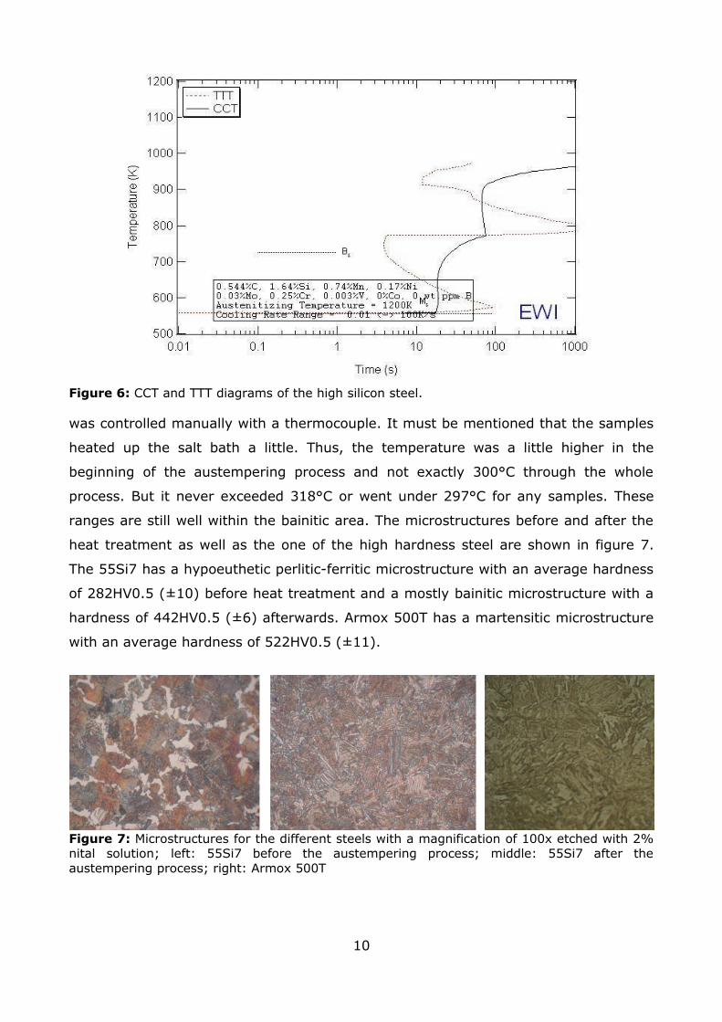
Figure 6: CCT and TTT diagrams of the high silicon steel.
was controlled manually with a thermocouple. It must be mentioned that the samples
heated up the salt bath a little. Thus, the temperature was a little higher in the
beginning of the austempering process and not exactly 300°C through the whole
process. But it never exceeded 318°C or went under 297°C for any samples. These
ranges are still well within the bainitic area. The microstructures before and after the
heat treatment as well as the one of the high hardness steel are shown in figure 7.
The 55Si7 has a hypoeuthetic perlitic-ferritic microstructure with an average hardness
of 282HV0.5 (±10) before heat treatment and a mostly bainitic microstructure with a
hardness of 442HV0.5 (±6) afterwards. Armox 500T has a martensitic microstructure
with an average hardness of 522HV0.5 (±11).
Figure 7: Microstructures for the different steels with a magnification of 100x etched with 2% nital solution; left: 55Si7 before the austempering process; middle: 55Si7 after the austempering process; right: Armox 500T
10

2.3 Laser-Welding and heat treatment
Eleven different bead on plate welding experiments were carried using an Ytterbium
Fibre Laser (YLR - 15000, IPG; see figure 8a). The parameters were kept the same for
all welding trials: the power was set to 4 kW and the welding speed to 1.5 m/min. The
focal spot was 3 mm under the sample surface. 15 liter Helium per second was used
as shielding gas.
Figure 8: The Ytterbium fibre laser(left) and the experimental setup.
The experiments differed in pre- and post-weld heat treatment and are listed in table
2. Heating was either carried out by a furnace or an induction coil. In all the
experiments that did not include furnace heating (I, II, VI-XI) a thermocouple was
spot welded 2 mm away from the welding track on the surface of the samples and
connected to a data logger to control the temperature in real time during welding and
capture the temperature characteristics in the heat affected zone. The induction coil
fixture was moved manually before or after welding and the power was also adjusted
manually in accordance to the temperature measurement. This procedure gave
surprisingly good results after only little practice and experience gathering. The
experimental set-up can be seen in figure 8b.
In the following, the ideas behind the different experiments are discussed.
Experiments I and II were carried out without any pre- or post-weld heat treatment to
investigate the general weldability of the given steels and to have a reference for the
other experiments. In the experiments III to VI rather conventional heat treatment
methods were carried out to see if they improve the welds in the bainitic steel. A
combination of pre- and post heating was used as well as separate trials. Preheating is
supposed to change the cooling curve after welding while post-weld heat treatment is
supposed to temper the zones which are hardened by the welding process. The
11

samples were heated up in a furnace except for sample VI which should show in
comparison with sample IV if short-time induction heating is capable of substituting
the less convenient furnace method.
Table 2: List of experiments; HT: heat treatment, PH: preheating, PWHT: post-weld heat treatment, Q&P: quenching and partitioning, QT: quenching temperature, PT: partitioning temperature, Pt: Partitioning time, N&G: nucleation and growth, TT: tempering temperature, Tt: tempering time
Experiments VII to IX were carried out to see if the quenching and partitioning
concept could be applied on welds to lower the final martensite content in the heat
affected zone or at least in a certain area of the heat affected zone. Critical
parameters in the quenching and partitioning heat treatment are the austenization
temperature and time, the quenching temperature and time and the partitioning
temperature and time. The austenization in the heat affected zone was no concern
since it should be done by the welding itself. The quenching temperature was chosen
to achieve a 50% martensite and 50% austenite microstructure according to the
equations in the literature [5]:
f m=1−e−1.1∗10−2∗M s−QT (1)
M s °C =539−432C−30.4Mn−7.5Si30Al (2)
where fm is the fraction of austenite that transforms into martensite, Ms is the
martensite start temperature, QT is the quenching temperature and the chemical
symbol in equation 2 represent the content of the particular alloying element. The
martensite start temperature of the 55Si7 steel is 274°C according to equation 2.
Consequently, a quenching temperature of 211 °C refers to a martensite content of
50%. A partitioning time of 90 seconds was chosen and the three experiments
differed in partitioning temperature which were 250°C, 320°C and 350°C,
respectively. In contrast to this, all the partitioning temperatures in the literature
12
Sample Steel HT Concept and detailsI 55Si7 no HTII Armox 500T no HTIII 55Si7 furnace “conventional”; PH and PWHT at 300 °C 1800sIV 55Si7 furnace “conventional”; PH at 300 °C 1800sV 55Si7 furnace “conventional”; PWHT at 300 °C 1800sVI 55Si7 induction “conventional”; PH 300 °C 300sVII 55Si7 induction Q&P; QT: 211 °C, PT: 250 °C, Pt: 90 secVIII 55Si7 induction Q&P; QT: 211 °C, PT: 320 °C, Pt: 90 secIX 55Si7 induction Q&P; QT: 211 °C, PT: 350 °C, Pt: 90 secX 55Si7 induction N&G; QT: 211 °C, TT:600 °C, Tt: 90 secXI Armox 500T induction N&G; QT: 300 °C, TT:600 °C, Tt: 90 sec

were lower than the martensite start temperature [5].
The last heat treatment tested was the only one which was also carried out with the
high hardness steel. The question was if it is possible to transform parts of the
austenite in the heat affected zone to martensite, exactly like in experiments VII to
IX, and transform the remaining austenite to ferrite or pearlite at higher temperatures
instead of stabilising it. The martensite could act as nucleation sites in this case to
shorten the transformation process of the other phases while the martensite itself
becomes tempered. Tempering Temperatures of 600 °C were chosen for both steels.
The calculated martensite start temperature for Armox 500T is 362 °C and the
resulting quenching temperature 299 °C. The difference of this heat treatment
compared to the quenching and partitioning one are the much higher transformation
temperatures. The difference compared to conventional quenching and tempering is
that the austenite is only partly transformed to martensite instead of completely.
2.3 Metallography
All the samples were cut perpendicular to the welding track and embedded in phenolic
resin. They were ground from 80 to 1200 grit size and afterwards polished with
diamond spray from 9 μm to 1 μm and silica suspension.
Microhardness measurements were done using a Matsuzawa MXT-CX tester. Two
tracks of test were run through the weld to get a hardness profile in dependence of
the distance to the weld centre (see figure 13a for clarification). One track was taken
1.5 mm and the other one 3 mm under the sample surface. The distance between the
tests were 250 μm, the load was 500 g and the loading time was 15 seconds.
Different etching methods were tried for both steels. In the end, a mixture of 30 ml
Glycerol (87%), 10 ml of nitric acid (65%) and 20 ml hydrofluoric acid (40%) turned
out to be most promising for 55Si7 and was used for microscopy. Armox 500T was
etched with 2% Nital solution. Different colour tint-etching methods for example the
one presented by De et al. [30] did not lead to satisfactory results.
Microstructual investigation were performed on a Olympus Vanox-T optical microscope
and a Jeol JSM 6460 LV scanning electron microscope (SEM).
13

2.4 Theoretical predictions of temperature characteristics in the HAZ
The temperature profiles in the heat affected zone have been modelled by Ashby and
Easterling [31]. There is one model for very thin plates and one for very thick ones. A
real weld can be assumed to be a mixture of these cases. The temperature T versus
time t can be expressed by the preheat temperature T0, the peak temperature Tp and
the time to cool from 800° to 500°C Δt which are again dependent on the welding
parameters. For thick plates the equations are:
T−T 0=θ1Δttexp −Δt
etθ1
T p−T 0 (3)
with
T p−T 0= 2πe
q /vρcr2
(4)
Δt= q /v2πλθ1
(5)
1θ1= 1773−T 0
− 11073−T 0
(6)
Here, e is 2.718 (base of natural logarithms), q/v the energy input (laser power/ laser
speed), ρc the specific heat per unit volume (density * heat capacity), r the distance
from the weld and λ the thermal conductivity.
For thin plates the equations are:
T−T 0=θ2 Δtt exp −θ 2
2 Δt2etT p−T 0
2 (7)
T p−T 0= 2πe q /vd 2
dρc2r(8)
Δt= q/ vd 2
4πλρcθ22 (9)
1θ22=
1773−T 0
2−1
1073−T 02 (10)
Here, d is the thickness of the plate [31]. Temperature against time graphs were
calculated at distances where the peak temperatures are the austenite start
temperature or the melting temperature, respectively, assuming that these are the
distances which limit the HAZ (see figure 9 for clarification where the tempered zone
is also defined as a part of the HAZ). The material properties used for the calculations
were taken from source [32] and are listed in table 3. For the welding parameters the
parameters of the actual experiment were used.
14

Table 3: Material properties for the 55Si7 steel.Units 55Si7
A3 temperature K 995
Melting temperature Tm K 1761
Volume thermal capacity ρc Jm-3K-1 4.5*106
Thermal conductivity λ Jm-1s-1K-1 41
Carbon equivalent Ceq weight% 0.76
Figure 9: Nomenclature of the different zones in a weld and the peak temperatures they refer to. A steel with 0.15 % carbon is taken as an example. Source: [31].
3. Results and discussion
3.1 Theoretical and practical temperature characteristics
Figure 10 shows theoretical temperature characteristics for welding with preheating at
300 °C by using the extreme approximations for very thick sheets (10a) and very thin
sheets (10b). This preheating temperature was also chosen for the practical
experiments because it leads to a temperature curve which goes through the lower
bainitic area instead of entering the martensitic area immediately after welding in the
theoretical prediction (10c). But this assumption has to be taken with caution since
the cooling curve as well as the CCT-diagram are based on mathematical models and
15

can differ in reality as can be seen in figure 11.
Figure 10: Theoretical temperature versus time curves after equations 3 and 7. The red curves represent the boundary between the FZ and the HAZ and the blue curves represent the boundary between the HAZ and the base material. a) Approximation for thick sheets (equation 3). b) approximation for thin sheets (equation 7).c) Cooling from the peak temperatures after the approximation for thick sheets on a logarithmic scale in respect of the constant cooling transformation diagram (figure 6).
Figure 11 shows the comparison between the theoretical cooling curve 2 mm away
from the weld centre and the measured one. It can be seen that the actual cooling is
well represented by the theoretical prediction for the experiment without any heat
treatment. But in the case of the experiment where the sample has been preheated at
300 °C the characteristics differ: the theoretical cooling curve approaches an
asymptote at 300 °C while the empirical one passes this value already around 80
seconds after welding. Thus, from the empirical temperature characteristic it can be
assumed that a mixture of bainite and martensite will form in the heat affected zone.
16

Figure 11: Comparison of the theoretical time-temperature-cooling-curves (red) and the practical experiment (blue) measured/calculated 2 mm away from the weld center; a) sample I; b) sample VI.
It has to be taken into account that the peak temperature of the experimental curve
stays clearly under the austenitic temperature even if the temperatures have been
measured in the heat affected zone. This is due to the fact that the data logger only
measured one value per second and was a little to slow to measure the peak
temperatures during welding. Nevertheless, the most important part, namely the
temperature characteristics before and after the welding peak could be recorded
sufficiently.
The theoretical model predicts that the peak temperature will be equal to the melting
temperature 2.6 mm away from the weld centre (for thick plates, or 1.2 mm for thin
plates) and equal to the austenitic temperature 3.4 mm (4.4 mm) away from the weld
centre. It can be seen in figure 13a that the fusion zone and the heat affected zone
are slimmer in the actual experiment.
Figure 12 shows the temperature characteristics of two of the quenching and
partitioning experiments. It can be seen that the general idea of the model curve
which can be seen in figure 5 could be reproduced. Of course it was not possible to
achieve cooling and heating slopes which are so steep due to the fact that quenching
takes place in air even if the cooling after laser beam welding is quite rapid. This leads
to longer quenching times before partitioning then in the work by Speer et al. [5]. But
at least it is guaranteed that the desired quenching temperature is actually reached
and held for three seconds in the material. Preheating at 140 °C for a short time was
necessary to achieve the desired quenching temperature. As discussed above, the
welding peak in the graph is again smaller than the probable one.
17

Figure 12: Experimental time-temperature-curves of the quenching and partitioning heat treatment measured 2 mm from the weld centre; a) partitioning temperature: 250 °C b) partitioning temperature: 320 °C.
3.2 Microstructural changes in the welds
3.2.1 The welding experiment without heat treatment
In the following, the microstructures that resulted from different welding experiments
are discussed. The microstructures of sample I are discussed in this paragraph and
will be the reference for the following samples.
Figure 13a shows an overview of the weld taken with the optical microscope. It can be
seen that the heat affected zone and the fusion zone are etched differently than the
base material. They show typical shapes and some cracks and pores can be seen.
Minor cracks or pores could be found in all the experiments and are not discussed any
further. The upper track of microhardness indents can also be seen in this figure.
Figure 13b shows an scanning electron micrograph of the boundary between the heat
affected zone and the base material. Microstructual differences can already be noticed
with this relatively small magnification and become more apparent in the following
pictures. The base materials can be seen in c) and d). It shows the typical carbide free
bainite structure consisting of laths of ferrite (darker etched) and retained austenite
films in between. In some cases the bainitic ferrite laths are arranged in the "feather-
like" sheave shape and in some cases they are just stacked. In contrast to the
basematerial, the fusion zone and the heat affected zone show no traces of bainite.
The microstructures are lesser etched and appear to consist mainly of martensite (see
e and f). This impression is confirmed by the results of the microhardness test which
18

Fig 13: Micrographs of sample I; a) overview over the different zones of the weld, 2.5x magnification; b) boundary between the heat affected zone and the base material, 800x; c) base material, 3500x; d) base material, 1500x; e) HAZ, 1500x; f) FZ; 3500x.
can be seen in figure 14: The hardness values are much higher in the heat affected
zone and in the fusion zone than in the base material and reach values up to
796HV0.5. The hardness in the tempered zone is slightly lower than in the base
material. It can be further concluded from this graph that the general shape of the
two curves does not change much. The main difference is that the fusion zone and
the heat affected zone are slimmer deeper in the sample. That is why only the 1.5
mm tracks are shown in later microhardness-graphs.
19

These results are not surprising. As expected, the fast cooling rate during welding lead
to martensite and unacceptably high hardness values which again will most likely lead
to embrittlement and makes welding of steels with such a high carbon content
problematic.
Figure 14: Microhardness values of sample I in dependence of the distance from the center of the weld. The black curve represents the track 1.5 mm under the sample surface, the grey one the track 3 mm under the sample surface. The lines between the measurement points are not extrapolations.
3.2.2 The conventional furnace heat treatment
Figure 15 shows that the conventional heat treatment methods lead to a decrease in
microhardness in the heat affected zone and in the fusion zone. But only the
experiment where pre- and post-weld heat treatment are combined (III) shows
acceptable values with a maximum hardness values of 504HV0.5 which is not much
harder than the base material.
The reason why preheating alone did not succeed can be explained by the
temperature characteristic of experiment VI (see figure 11b): despite the fact that
cooling is retarded by preheating and the curve enters the bainitic nose, the
martensite start temperature is reached quite quickly. The unsatisfactory results of
the post-weld heat treatment can be explained by the temper-resistance of silicon
steels at relatively low temperatures [16].
20

Figure 15: Microhardness values of sample I, III, IV and V.
Figure 16a) and b) show the microstructure of the heat affected zone and the fusion
zone of sample III. It appears to be bainite which only differs to the base material in
ferrite lath size and arrangement. In contrast to this, only small areas of bainitic and
Widmannstätten ferrite can be found in sample IV (c and d) while a large part of the
microstructure is lesser etched and is most likely to be martensite. Thus, it can be
concluded that post-weld heat treatment can not only temper welds but also keep
them over the martensite start temperature in preheated samples with retarded
cooling rates which leads to a more complete bainitic transformation compared to
simply preheated samples. The micrographs of sample V (e and f) are difficult to
interpret even if the hardness values and the heat treatment history are known.
21

Figure 16: Micrographs of the conventionally heat treated welds; a) sample III, HAZ; b) sample III, FZ; c) sample IV, HAZ; d) sample IV, FZ; e) sample V, HAZ; f) sample V, FZ; 3500x.
3.2.3 Comparison between furnace and induction heating
Experiment VI shows that induction heating is not only a more convenient alternative
to furnace heating but also can lead to satisfactory hardness values and
microstructures. This has already been stated by Pinto et al. in their work on S690QL
steel [33]. The microstructures in the fusion zone of the induction preheated sample is
actually very similar to the one preheated in the furnace (see figure 17 and compare
22

figure 16d and 18b). The heat effected zone shows even lower hardness values and
more areas of bainite then sample IV.
Figure 17: Microhardness values of sample I, IV and VI.
Figure 18: Micrographs of sample VI; a) HAZ; b) FZ; 3500x.
3.2.4 The quenching and partitioning experiment
The problems of using the quenching and partitioning concept for improving the
microstructure in the heat affected zone are obvious: since the peak temperatures
differ, the resulting quenching temperatures also differ. So, the temperature graphs
shown in figure 12 are only valid for certain areas within the heat affected zone.
Secondly, the exact microstructual of this concept results have not been completely
understood yet.
23

Figure 19: Microhardness values of sample I, VII, VIII and IX.
Nevertheless, the hardness values in figure 19 are promissing, especially for higher
partitioning temperatures. It can be seen that the values in the fusion zone and in the
heat affected zone are nearly the same as the values in the base material at a
partitioning temperature of 350 °C. A comparison between the microstructure in this
sample and the microstructures of first trials of applying the quenching and
partitioning concept found in the literature [5] can be seen in figure 20. But before
discussing the images the basic differences between the experiments should be
pointed out: firstly, the composition of the steels and therefore values like the
martensite start temperature differ. Secondly, the samples in the literature had been
prepared by longer annealing in a furnace, quenching in a tin bath and partitioning in
a salt bath. The sample in figure 20c) and all the other samples in the literature were
annealed in the intercritical region to maintain approximately 50% of ferrite and they
were always partitioned at temperatures below the martensite start temperature
which was estimated to be 473 °C. Despite all these significant differences, figures
20a) and c) look quite similar. The major difference is the lack of the intercritical
ferrite (dark, featureless areas in figure c) in the weld which is straight forward
because the peak temperature in the heat affected zone was above the austenization
temperature. The blocky structure which is described to be either martensite-
austenite or retained austenite as well as the lath-like features (indicated by the
arrow) are both present in sample IX, only the size and shape of the laths differs. It is
unclear if these lath-like features actually arise from the quenching and partitioning
24

process or by usual bainitic growth [5].
Figure 20: Micrographs of the quench and tempered samples: a) sample IX, HAZ, 3500x; b) sample VII, HAZ, 3500x; c) reference image from literature [5]
The only sample that was partitioned at temperatures below the martensite start
temperature showed a martensitic microstructure in the weld like it could be found in
sample I (compare figure 13e and 20b). Apparently, the temperatures were not
sufficient for carbon partitioning.
As the discussion shows the mechanism in these weld samples are not fully
understood. But the promising hardness values show that it is a very interesting
concept of welding steels with a high silicon and carbon content which should be
investigated more deeply.
3.2.5 The nucleation and growth experiment
Experiments X and XI led to low hardness values within the weld and in the base
material (see figure 21). They were even lower then the hardness values in the initial
25

Figure 21: Microhardness values of sample I and X (left) and sample II and XI (right).
material. It can be seen in figure 22 and 23c) that no ferritic structures evolved at any
nucleation sites and welds consists of a microstructure which is most likely tempered
martensite. So apparently the whole treatment does not differ from conventional post-
weld heat treatment.
Figure 22: Micrograph of sample X, 3500x.
Figure 23: Microstructures in the Armox 500T steel: a) base material; b) II, HAZ; c) XI, HAZ;
100x.
In the heat affected zone of the armour steel the microstructure is actually quite
26

similar to that of the base material (compare figure 23a) and b)). And in this case,
the tempered zone appears to be the most problematic area in the weld since the
hardness is lowered under the hardness of the base material.
4 Conclusion and future work
1. Laser beam welding of 55Si7 leads to martensite, unacceptably high hardness
values, porosity and crack formation in the welds which lowers the mechanical
properties of work piece and prevents the use in practice.
2. Different conventional and new heat treatment methods can lead to more
favourable microstructures and significantly lower hardness values in the weld.
3. Induction heating is a convenient and appropriate substitution for furnace heating
when it comes to local pre- and post-weld heat treatment.
4. The quenching and partitioning concept applied on weld heat treatment shows very
promising hardness values and interesting microstructures.
5. The first trial of applying a nucleation and growth concept on welds did not give rise
to any satisfactory results.
6. Further investigation on the microstructures should be carried out to answer open
questions.
7. Mechanical tests should be carried out on welds which show the best results in this
work to find out if the improvement of microstructure really improves the mechanical
properties.
8. More welding experiments following the quenching and partitioning concept with
changing the parameters can lead to a better understanding and improved welds. It
would be especially interesting to vary the initial quenching temperature in several
steps to clarify the difference to conventional post-weld heat treatment.
9. Induction heating should be used for combined pre- and post-weld heat treatment
and it should be tried if shorter heating times can be sufficient to make the process
more applicable in praxis.
27

5 References
[1] Bhadeshia HKDH: Bainite in steels; 2nd edition; IOM Communications Ltd; 2001
[2] Lawrynowicz Z, Barbacki A: Features of bainite transformation in steels; Advances in materials science, Vol. 2, 2002, 5-32
[3] Bhadeshia HKDH, Edmonds: The Bainite Transformation in a Silicon Steel; American Society for Metals and the Metallurgical Society of AIME; Vol. 10A; 1979; 895-907.
[4] Bosnjak B, Radulovic B, Pop-Tonev K, Asanovic V: Influence of Microalloying and Heat Treatment on the Bainitic Reaction in Austempered Ductile Iron; Journal of Materials Engineering and Peformance; Vol 10(2); 2001; 203-211
[5] Speer JG, Streicher AM, Matlock DK, Rizzo F, Krauss G: Quenching and partitioning: a fundamentally new process to create high strength TRIP sheet microstructures; In: Damm EB, Merwin MJ (editors): Austenite formation and decomposition; The Iron & Steels Society and TMS; 2003; 505-522
[6] Navara E, Zimba J: Ausferritic ferrous alloys - A challenge to industry and research. Acta Metallurgica Slovaca 10; 2004; 244-252.
[7] Hillert M, Purdy GR: On the misuse of the term bainite; Scripta materialia 43; 2000; 831-833. [8] Borgenstam A, Hillert M, Ågren J: Metallographic evidence of carbon diffusion in the growth of bainite; Acta Materialia; 2009.
[9] Li Y, Xiang C: Microstructure and mechanical properties of austempered high silicon cast steel; Materials Science and Enginnering A308; 2001; 277-282
[10] Putatunda SK: Influence of austempering temperature on microstructure and fracture toughness of a high carbon, high silicon and high-manganese cast steel; Materials and Design 24; 2003; 435-443
[11] Bhadeshia HKDH, Edmonds DV: Bainite in silicon steels: new composition-property approach Part 1; Metal Science; Vol. 17; 1983; 411-419
[12] Bhadeshia HKDH, Edmonds DV: Bainite in silicon steels: new composition-property approach Part 2; Metal Science; Vol. 17; 1983; 420-425
[13] Garcia-Mateo C, Caballero: Ultra-high-strength Bainitic Steels; ISIJ Internatinal, Vol. 45, No 11, 2005, 1736-1740
[14] Caballero FG, Bhadeshia HKDH, Mawella KJA, Jones DG: Very strong low temperature bainite; Material Science and Technology, Vol.18, 2002, 279-284
[15] Caballero FG, Miller MK, Babu SS, Garcia-Mateo C: Atomic scale observations of bainite transformation in a high carbon high silicon steel; Acta Materialia 55; 2007; 381-390
28

[16] Vuorinen E, Pino D, lundmark J, Prakash B: Wear characteristic of Surface Hardened Ausferritic Si-Steel; Proceedings of Sino-Swedish Structual Materials Synopsium; 2007; 245-248
[17] Caballero FG, Bhadeshia HKDH: Very strong bainite; Current Opinion in Solid State and Materials Science 8; 2004; 251-257
[18] Bhadeshia HKDH: Large chunks of very strong steel; Millennium Steel; 2005; 25-28
[19] Sun Z, Ion JC: Laser welding of dissimilar metal combinations; Journal of Material Science 30, 1995, 4205-4214
[20] Mazumder J: Laser-Beam Welding; In: Welding, brazing and soldering; In: ASM handbook Vol 6; 1993
[21] Ion JC: Laser processing of engineering materials - principle, procedure and industrial application; Elsevier Butterworth-Heinemann; 2005
[22] Duley WW: Laser welding; John Wiley & Sons Inc.; 1999
[23] Somers BR: Introduction to the Selection of Carbon and Low-Alloy Steels; In: Welding, brazing and soldering; ASM handbook Vol 6; 1993
[24] Kou S: Welding metallurgy; John Wiley & Sons Inc.; 1987
[25] Bach, FW, Haferkamp H, Bunte J, Cordini P, Bormann A: Verbessertes Umformverhalten durch serielle induktive Nachwärmung von laserstrahlschweißnähten; Materialwissenschaft und Werkstofftechnik 33, 410, 414; 2002
[26] Sun DQ, Gu XY, Liu WH, Xuan ZZ: Welding consumable research for austempered ductile iron (ADI); Materials Science and Engineering A 402; 2005; 9-15
[27] Bhadeshia HKDH, Lord M, Svensson LE: Silicon-Rich Bainitic Steel Welds; Proceedings of International Conference: Joining & Welding Solutions to Industrial Problems, JWRI, Osaka University, 2003, 43-52
[28] Speer J, Matlock DK, De Cooman BC, Schroth JG: Carbon partitioning into austenite after martensite transformation; Acta Materialia 52; 2003; 2611-2622
[29] TTT/CCT predictions; EWI virtual joining portal; 2008; http://calculations.ewi.org/vjp/secure/TTTCCTPlots.asp, last visited 2009-03-25
[30] De AK, Speer JG, Matlock DK: Color tint etching for multiphase steels; Advanced Materials & Processes, 2, 2003, 27-30
[31] Ashby MF, Easterling KE: A first report on diagrams for grain growth in welds; Acta metallurgica, Vol 30, 1982, 1969-1978
[32] Ion JC, Easterling KE, Ashby MF: A second report on diagrams of microstructure and hardness for heat-affected zones in welds; Acta metallurgica, Vol 32, 1984, 1949-
29

1962
[33] Pinto H, Corpas M, Guio JA, Pyzalla AR, Jahn A, Standfuß J: Microstructure and Residual Stress Formation in Induction-Assisted Laser Welding of the Steel S690QL; steel research int. 80, 1, 2009, 39-49
30
Related Documents


