The Phu My Bridge A case study by Tony Gee and Partners of staged construction and dynamic analysis of the cable- stayed bridge in Vietnam. The People’s Committee of Ho Chi Minh City on behalf of the Socialist Republic of Vietnam commissioned the con- struction of a bridge crossing the Sai Gon river. The invest- ment owner of the project, the Phu My Bridge Corporation (PMC), commissioned the UK based consulting firm Tony Gee and Partners LLP (TGP) to undertake an independent Technical Design Investigation Consultancy. The main con- tractor for the project is the BBBH consortium which is a joint venture between Bilfinger Berger and Baulderstone Horni- brook. BBBH are also responsible for the design of the bridge through their design consultants. The scope of TGP’s services under the contract spread over a broad range of checks and overviews but particularly included detailed numerical and analytical checks on the bridge structure using high end engineering software. The Cable-stayed Structure The all-concrete cable stayed structure comprises a three- span arrangement with spans of 162.5m + 380m + 162.5m. The 27.5m wide superstructure comprises a classical Pi-sec- tion RC deck with two edge girders connected by regularly spaced transverse post-tensioned girders. The main girders are also post-tensioned in the main span region. The RC pylons are hollow box H-shaped shafts and feature draped legs of a variable cross section that are connected by post- the inaugural issue of LARSA’s quarterly journal LARSA, Inc.’s January 2008 4D JOURNAL Welcome Message from LARSA’s president Ali Karakaplan page 2 News in Brief page 2 L-Tips: Tools tor rapidly modeling post-tensioning tendons page 3 Meet The 4D Team: Ali Koch page 6 What’s Ahead: Composite section construction activities page 7 Conference Schedule page 8 continued on page 4 ALSO INSIDE . . .

Welcome message from author
This document is posted to help you gain knowledge. Please leave a comment to let me know what you think about it! Share it to your friends and learn new things together.
Transcript

The Phu My Bridge
A case study by Tony Gee and Partners of staged construction and dynamic analysis of the cable-stayed bridge in Vietnam.
The People’s Committee of Ho Chi Minh City on behalf of the Socialist Republic of Vietnam commissioned the con-struction of a bridge crossing the Sai Gon river. The invest-ment owner of the project, the Phu My Bridge Corporation (PMC), commissioned the UK based consulting firm Tony Gee and Partners LLP (TGP) to undertake an independent Technical Design Investigation Consultancy. The main con-tractor for the project is the BBBH consortium which is a joint venture between Bilfinger Berger and Baulderstone Horni-brook. BBBH are also responsible for the design of the bridge through their design consultants.
The scope of TGP’s services under the contract spread over a broad range of checks and overviews but particularly included detailed numerical and analytical checks on the bridge structure using high end engineering software.
The Cable-stayed Structure
The all-concrete cable stayed structure comprises a three-span arrangement with spans of 162.5m + 380m + 162.5m.
The 27.5m wide superstructure comprises a classical Pi-sec-tion RC deck with two edge girders connected by regularly spaced transverse post-tensioned girders. The main girders are also post-tensioned in the main span region. The RC pylons are hollow box H-shaped shafts and feature draped legs of a variable cross section that are connected by post-
the inaugural issue of LARSA’s quarterly journal
LARSA, Inc.’s January 2008
4D JOURNAL
Welcome Message from LARSA’s president Ali Karakaplan
page 2
News in Briefpage 2
L-Tips: Tools tor rapidly modeling post-tensioning tendons
page 3
Meet The 4D Team: Ali Kochpage 6
What’s Ahead: Composite section construction activities
page 7
Conference Schedulepage 8
continued on page 4
ALSO INSIDE . . .

2 4DJournal—January2008
About the 4D JOURNAL
LARSA 4D is analysis and design software for bridges, buildings, and other structures, developed by LARSA, Inc. in New York, USA. This journal pub-lishes quarterly and is sent as a courtesy to our clients and corporate friends. We welcome feedback and suggestions for future stories to [email protected].
Welcome Message
We would like to welcome you to our fi rst issue of the 4D JOUR-NAL. This quarterly publication will share and exchange informa-tion among LARSA 4D users, and we hope to shape the publication around suggestions and contribu-tions from you. The JOURNAL will update you on the features we are developing and interesting ongoing projects using LARSA 4D.
In the issues later this year, you can expect to read about new ca-pabilities for design. LARSA 4D is growing from a “4D” analysis pack-age useful for any type of complex structure, such as cable-supported structures, to an analysis and design tool with a special focus for bridge engineers. Bridges represent the most challenging structures due to their exposure to the environ-ment, loading conditions, seismic response, and construction sequence. Engineering technology has made tremendous ad-vances in the past decade, and we hope to keep LARSA 4D ahead of the curve.
Engineers require the ability to predict the performance level of structures with a prescribed degree of confi dence. Shortcuts are no longer an option for the types of bridges now being built, and the margin for error is narrowing. Now 20 years in the business of rigorous analysis, we will continue the development of analytic tools designed with our clients’ needs in mind.
It has only been through developing new capabilities with clients, one-on-one, that has allowed us to produce cut-ting-edge software. Material time effects, tendons, moment-curvature analysis, and steel I girder design, among other components of LARSA 4D, were developed in this way. We greatly value our close relationships with our clients and enjoy working together on extending the software for whatever new needs arise.
Best wishes for the new year,
Ali D. Karakaplan, Eng.Sc.D.President, LARSA, Inc.
LARSA, Inc.105 Maxess Road Melville | New York | 117471-212-736-4326 [email protected]
News in BriefCompany and software updates of note:Our new design module performs AASHTO LRFD 2006/7 code check on curved and skewed steel I, plate, and box girder bridges. A wizard-like interface can be used to generate bridge mod-els or perform code checking on existing LARSA models. This module complements the analysis capabilities of the program in our aim to be a complete analysis & design package.
Moment curvature analysis can now be per-formed on concrete sections from Tools > Mo-ment Curvature Analysis. The moment-curvature curves computed can be used for plastic analysis using hysteretic members.
A new iterative shape fi nding tool has been add-ed to the program under the Tools menu. This tool fi nds the initial state of the structure so that after loading, including staged construction activities and time effects, the deformed geometry reaches a certain state. It has been used successfully to fi nd the initial prestress on the cables of a cable-stayed bridge and the main suspender in a suspension bridge so that the deformed structural geometry matches the intended architectural form.
Our relationship with Bentley Systems has reached an end. In 2004, Research Engineers—subsequently incorporated into Bentley in 2005—partnered with us and became a reseller of LARSA products. The reseller agreement was mutually terminated this month.
∎
∎
∎
∎

3
How to place tendons rapidly using the Model DataExplorer and the Tendon Editor
Each issue of the 4D Journal will feature a short guide to an aspect of LARSA 4D that you may not already be familiar with.
Tendons in LARSA 4D are used to model internal and external pre- and post-tensioned strands within beam sections. The program computes the resulting forces on the beam elements along 3D tendon paths based on the curvature and other properties of the tendon specifi ed by the user, taking into account long-term time effects such as steel relaxation. Because cross-sections frequently contain several to a dozen tendon ducts, the ability to model tendons rapidly in a LARSA 4D model can be very important.
While tendon data can be entered entirely through the Geometry > Ten-dons spreadsheet, three tools speed up the process of entering tendon geometry: drawing tendons from a member chain, the Tendon Editor, and the Model Data Explorer’s tendon right-click menu.
Drawing Tendons
One way to create a tendon quickly is to defi ne it based on selected mem-bers. You will need to have selected just the members through which the tendon passes, so Unselect All.
You could use the standard graph-ical selection tools to click on each of the members that the tendon passes through to select them—i.e. the por-tion of the girder the tendon goes through, if this is a bridge model. However, selecting members one by one is a tedious process and is in most cases unnecessary.
Instead, fi rst go to the graphics window and turn on the Pointer Tool (the arrow-like tool in the toolbar). Then click any member that the ten-don passes through with the right mouse button. A menu of useful com-mands to apply to the particular mem-ber clicked is shown, such as ‘Select’, ‘Rotate Principle Axis’ (90 degrees), and ‘Reverse Direction’. See Figure 1.
Click on the ‘Select Chain’ command. LARSA will select that member and then look at which members it is con-nected to at either end and select all of those up and down the model so long as the members don’t make any sharp turns.
This command can be used to se-lect entire girders, tall columns made of multiple member elements, etc. very quickly.
With the so-called chain of mem-bers selected, go to Draw > From Se-lected Members > Tendon. See Figure 2. A tendon record is created and set up to pass through the selected chain of members. The Tendon Editor is also brought up for the new tendon.
The Tendon Editor
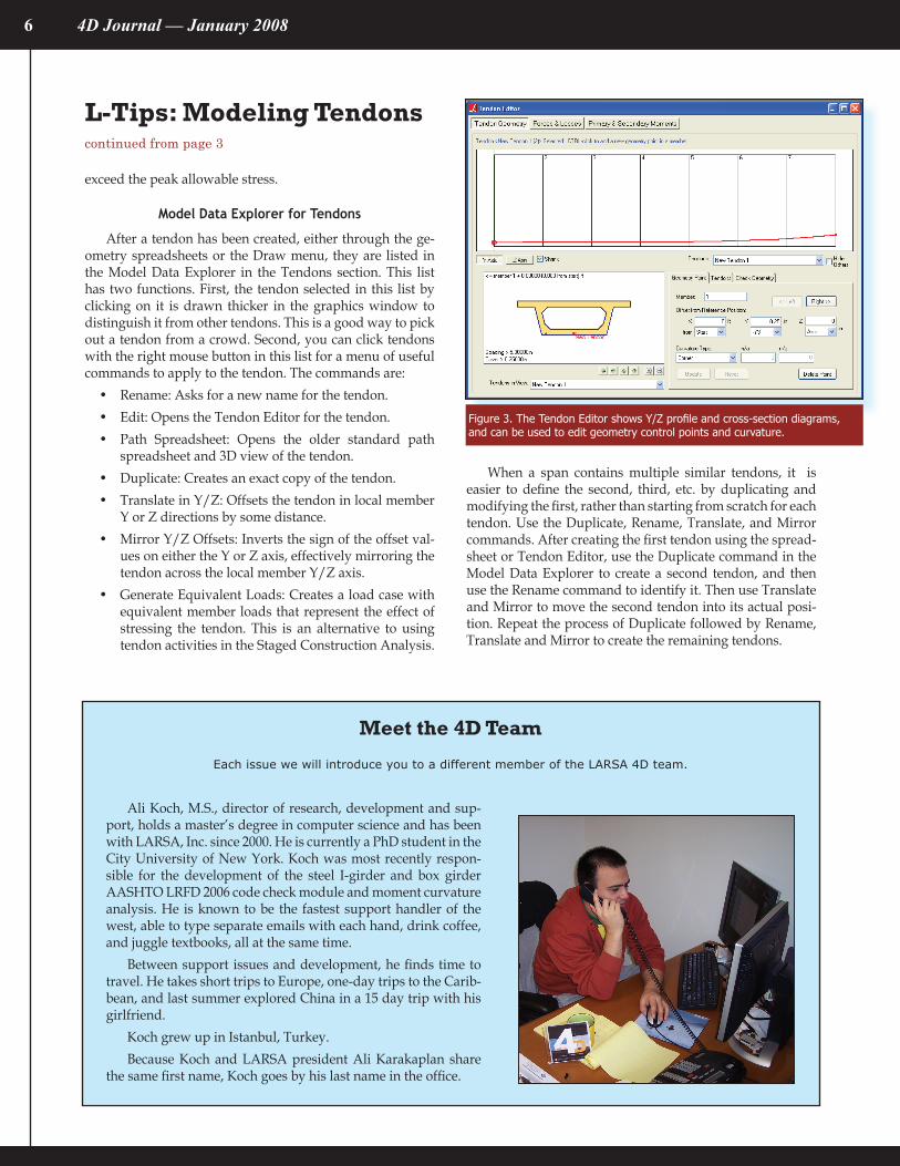
The Tendon Editor is used to enter the geometry of the tendon: the profi le of the tendon through the members it passes through. The Tendon Editor is an alternative to the (older) standard tendon path spreadsheet. The path spreadsheet opens with a 3D view of the tendon. The Tendon Editor, on the other hand, shows horizontal and
vertical profi le diagrams and a cross-section diagram. In a curved bridge, these profi le diagrams factor out the curvature so that it is easier to see the entire profi le at once, compared to the 3D view, and the cross-section shows all of the tendons passing through a member at any location.
The paths of tendons are con-trolled by a series of geometry points: shown as fi lled circles in the Tendon Editor profi le images. To change the tendon’s profi le, you can click the ge-ometry points and set their locations by offset distances from a member’s reference axis (which is usually the centroid, but can be positioned else-where in the Section Composer) or from the extreme edges of the member where section Stress Recovery Points are usually set. Curvature options at geometry points can also be set in the editor.
Tendon material, jacking, and other information must still be set in the Geometry > Tendons spreadsheet. After entering or modifying the pro-posed jacking force, always remember to right-click the tendon in the spread-sheet and choose Compute Jacking Force so that LARSA will ensure that the force along the tendon does not
Figure 1. Unselect All, and then right-click a member. The “Select Chain” command will select it and all of the members up and down from that member that form a connected “chain”.
Figure 2. This command creates a tendon passing through the selected members.
continued on page 6
L-Tips

4 4DJournal—January2008
tensioned cross beams. The tie-down piers are of solid RC construction and are integrally connected to the deck. The 144 cable stays are orientated in a semi-harp confi guration in two symmetrical cable planes.
Modelling and Analysis
In view of the high level of complexity associated with the analysis a global 3D model comprising representative beam and cable elements was developed. In order to econo-mize on data preparation and to make the modelling pro-cess more effi cient, a database was constructed in LARSA Section Composer for generating the section properties of the prismatic and non-prismatic members comprising the global model. This database was interfaced with the global model using the facilities provided within the software.
Additionally, the model also featured the ‘construction’ and ‘de-construction’ of a variety of temporary works that were installed and sequentially removed at various stages during the construction of the cable stayed structure. Use was made of linear and non-linear springs in order to simu-late such scenarios in conjunction with members represent-ing the temporary works. Appropriate 6x6 stiffness matrices were also developed to model the soil-structure interaction between the large diameter RC piled foundations under the main pylons and the abutments.
TGP principally used LARSA 4D for a broad range of linear as well as non-linear static and dynamic analyses for the cable stayed structure including:
staged construction with time-dependent creep and shrinkage effectsglobal and differential temperature effectsextraction of eigenmodes and eigenfrequenciesdynamic seismic response spectrum analysisship impact analysiscable replacement and nonlinear push-over cable-snap analysis
Key aspects of some of the analyses undertaken by TGP are briefl y outlined below.
•
•••••
Staged-construction Analysis (SCA)with Time-dependent Effects
A major component of the analytical work involved the staged construction analysis of the cable stayed structure in-corporating time dependent effects such as creep, shrinkage and relaxation to CEB-FIP 90.
Key aspects of the SCA are outlined below.The general sequence of construction input in the SCA was based upon the construction program provided by the contractor. The emphasis of this analysis was to closely model the evolving geometry, force distribu-tion, stiffness and material character of the structure with reference to the applied loading as well as time. Relevant stages of superstructure construction also accounted for the installation, sequential movement as well as release of the erection gantry.A major input in this analysis comprised the applica-tion of pre-determined forces applied to various cable stays during the process of stay installation. These forces were applied and managed at appropriate stag-es using the facilities provided within the software.
•
•
“In the instance of Phu My cable stayed bridge, LARSA 4D provided us with a versatile analytical tool for investigating the structure under a variety of static and dynamic load effects. We particularly found useful the range of options it offered with regard to staged construction and dynamic seismic analyses.”
— Sam Khan, Principal Engineer,Tony Gee and Partners
Phu My Cable Stayed Bridge, VietnamTony Gee and Partners LLP, U.K.
continued from cover

�
Temporary supports, members and falsework in-stalled and removed during the construction were also modelled. These included temporary bearings, wind buffeting cables and propping supports. Some tempo-rary members were assigned unidirectional stiffness such as ‘tension-only’ and ‘compression-only’. The
post-tensioning tendons installed in various members at different stages were also modelled.
The SCA yielded the build-up of stresses in the members including those locked-in during construction. In the post-closure phase, further stages were investigated for time de-pendent effects up to 125 years into the life of the structure.
Dynamic Seismic Analysis
The dynamic seismic response of the structure was in-vestigated by carrying out a multimodal eigenvalue analy-sis which was followed by a Response Spectrum Analysis to AASHTO LRFD.
The dynamic seismic analysis focussed on the following key aspects.
Appropriate representation of the material and struc-tural character of the structure as well as the mass dis-tribution.Extraction of the first 100 eigenmodes and eigenfre-quencies to yield an appropriate cumulative mass
•
•
•
participation in the three principal directions.Carrying out a multimodal dynamic response spec-trum analysis using site-specific parameters and com-bining the extracted forces in accordance with the codal provisions.
Nonlinear Cable-snap Pushover Analysis
As opposed to the cable change scenario, which was considered as a controlled event, the cable-snap scenario was modelled as a nonlinear pushover scenario incorporat-ing the strand-by-strand fracture of a critical cable stay. The basic impact dynamic force considered in the analysis was derived from the Post-tensioning Institute Guide Specifica-tion for Stay Cable Design Testing and Installation, 2000.
Ship Impact Analysis
The ship impact analysis was undertaken as a pseudo-dynamic analysis in which the dynamic force resulting from ship impact was applied in accordance with the provisions of AASHTO Guide Specification and Commentary for Ves-sel Collision Design of Highway Bridges. Further analysis in this regard was also carried out using proprietary software. As an additional consideration the ship impact scenario was initially investigated under a transient dynamic force. This course however was not pursued in detail because of the lack of project-specific information.
(Text and figures courtesy of Tony Gee and Partners.)
•
Figure 1. The cable stayed structure during various stages of construction as modelled in LARSA 4D.
Figure 2. Selected output from the multi-modal eigenvalue analysis carried out in LARSA 4D.
6 4DJournal—January2008
Meet the 4D Team
Ali Koch, M.S., director of research, development and sup-port, holds a master’s degree in computer science and has been with LARSA, Inc. since 2000. He is currently a PhD student in the City University of New York. Koch was most recently respon-sible for the development of the steel I-girder and box girder AASHTO LRFD 2006 code check module and moment curvature analysis. He is known to be the fastest support handler of the west, able to type separate emails with each hand, drink coffee, and juggle textbooks, all at the same time.
Between support issues and development, he fi nds time to travel. He takes short trips to Europe, one-day trips to the Carib-bean, and last summer explored China in a 15 day trip with his girlfriend.
Koch grew up in Istanbul, Turkey.Because Koch and LARSA president Ali Karakaplan share
the same fi rst name, Koch goes by his last name in the offi ce.
Each issue we will introduce you to a different member of the LARSA 4D team.
L-Tips: Modeling Tendonscontinued from page 3
exceed the peak allowable stress.
Model Data Explorer for Tendons
After a tendon has been created, either through the ge-ometry spreadsheets or the Draw menu, they are listed in the Model Data Explorer in the Tendons section. This list has two functions. First, the tendon selected in this list by clicking on it is drawn thicker in the graphics window to distinguish it from other tendons. This is a good way to pick out a tendon from a crowd. Second, you can click tendons with the right mouse button in this list for a menu of useful commands to apply to the tendon. The commands are:
Rename: Asks for a new name for the tendon.Edit: Opens the Tendon Editor for the tendon.Path Spreadsheet: Opens the older standard path spreadsheet and 3D view of the tendon.Duplicate: Creates an exact copy of the tendon.Translate in Y/Z: Offsets the tendon in local member Y or Z directions by some distance.Mirror Y/Z Offsets: Inverts the sign of the offset val-ues on either the Y or Z axis, effectively mirroring the tendon across the local member Y/Z axis.Generate Equivalent Loads: Creates a load case with equivalent member loads that represent the effect of stressing the tendon. This is an alternative to using tendon activities in the Staged Construction Analysis.
•••
••
•
•
When a span contains multiple similar tendons, it is easier to defi ne the second, third, etc. by duplicating and modifying the fi rst, rather than starting from scratch for each tendon. Use the Duplicate, Rename, Translate, and Mirror commands. After creating the fi rst tendon using the spread-sheet or Tendon Editor, use the Duplicate command in the Model Data Explorer to create a second tendon, and then use the Rename command to identify it. Then use Translate and Mirror to move the second tendon into its actual posi-tion. Repeat the process of Duplicate followed by Rename, Translate and Mirror to create the remaining tendons.
Figure 3. The Tendon Editor shows Y/Z profi le and cross-section diagrams, and can be used to edit geometry control points and curvature.
7
What’s AheadComposite Section Construction Activities
The What’s Ahead section highlights some of the new program capabilities we have in the works.
When the components of a single cross-section are assembled at differ-ent times, or when parts of a cross-sec-tion of different materials are behaving independently with respect to time-dependent material effects, composite section construction must be used to maintain the continuity of behavior of a single cross-section. A composite member is a single continuous line element made up of shapes of differ-ent materials or of shapes constructed or cast at different times. Coming to LARSA in 2008 are new capabilities for composite members.
Expect the program capabilities de-scribed below to be released later this year in the coming major update to LARSA software. They are currently in a testing phase but can be previewed upon request.
Composite members are defined in
the LARSA Section Composer. While members made of multiple materials can already be modeled using the Sec-tion Composer, they cannot undergo time-dependent material effects and the shapes that make up composite
members must all be constructed in the model at the same time.
Composite Member Element
The new composite construction capabilities coming in 2008 allow each shape that makes up a complete cross-section to be cast at different points during Staged Construction Analy-sis. Further, each shape may undergo creep, shrinkage, the time effect on elastic modulus, and thermal loads independently. These effects are com-puted separately for each shape and then transformed and applied to the member’s overall centroid automati-cally. For creep, the stress and strain history of each shape is maintained independently.
The casting of shapes at different times and the differential effect of
the time-effect on elastic modulus on parts of a section with multiple mate-rials causes the centroid of members
to move over time. This is also auto-matically accounted for.
A common use of composite con-struction will be to model a girder made up of a steel or concrete tub and a concrete plate cover which are cast at different times, but when it is desir-able to consider the tub and cover a single cross-section. This might be be-cause they act together continuously along the length of the girder.
While a more detailed finite-ele-ment model may treat the tub and cover as independent elements, such a model could fail to capture the con-tinuity of the connection between the tub and cover along the length of the girder. In a finite-element model of the girder, the continuity must be cap-tured by rigidly connecting the girder to the deck at regular intervals along the bridge. One might use Member End Offsets or rigid elements (mem-bers with artificially high stiffness) to do this. But creating connections at small intervals is a highly labor-in-tensive task. Composite members in-stead model the continuity but allow for some degree of independence of their parts.
Composite Section “States”
Composite section “states’” deter-mine which shapes are active at any given time. A shape can be included in a state with weight and stiffness, weight only as a simple method to model concrete before it sets, or stiff-ness only if the weight of a composite part has been modeled independently of automatic self-weight computation. Weight-only is an alternative to using time-dependent material properties and setting the casting day.
The composite state of a member can be changed as an activity during Staged Construction Analysis. Load-ing, including self-weight, and time-dependent material effects like creep
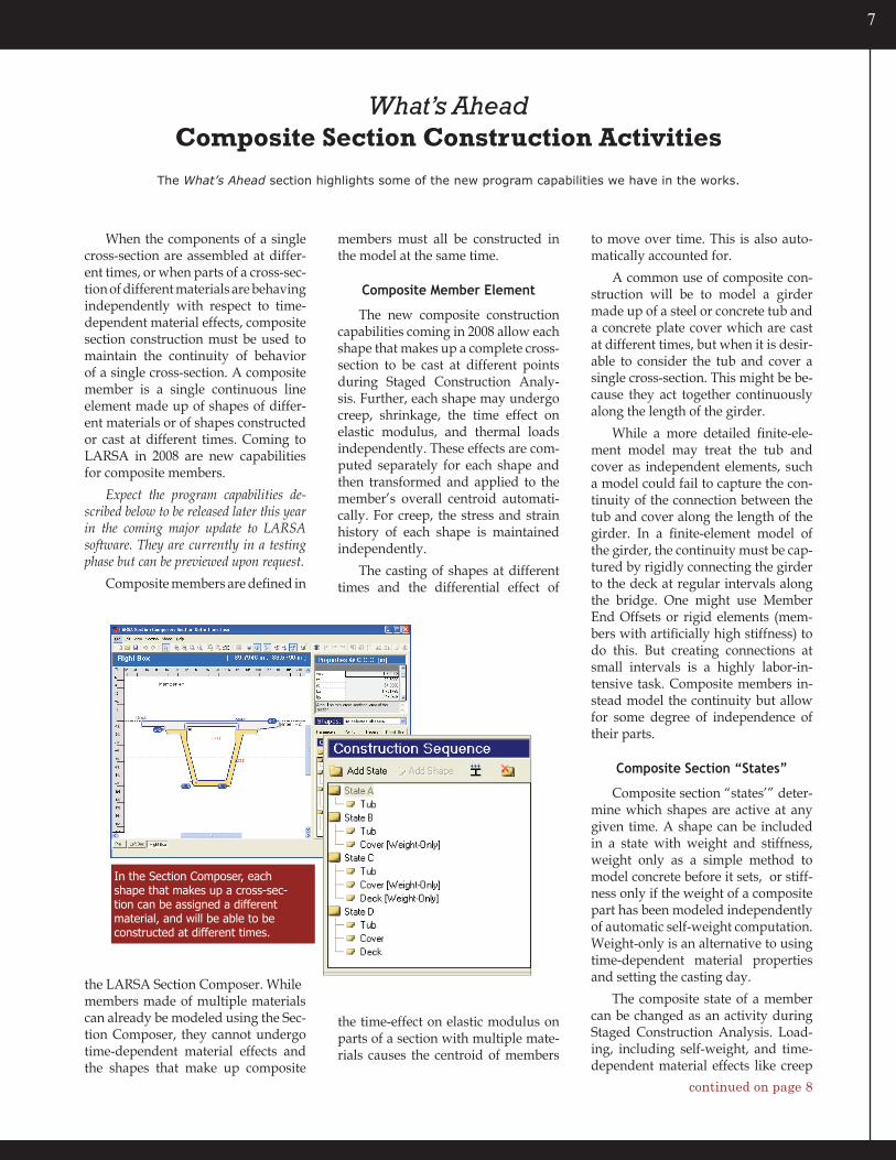
In the Section Composer, each shape that makes up a cross-sec-tion can be assigned a different material, and will be able to be constructed at different times.
continued on page 8

� 4DJournal—January2008
are applied on a shape-by-shape basis to whichever shapes are active in a mem-ber’s current composite state. Forces are transformed as needed from a shape’s centroid to the member’s overall cen-troid.
Composite construction affects member stresses as well. Stresses will reflect the possibly different strains in each shape that makes up a member, as well as the different modulus of elastic-ity of each shape, and the differential changes in modulus of elasticity over time for each shape.
New Composite Construction Activities
Composite section construction is an addition to the Staged Construction
Analysis. Two new activity types be-come available:
Cast Concrete: In a time-dependent staged construction analysis, this ac-tivity sets the casting day for concrete shapes within composite members. Dif-ferent casting days can be set for dif-ferent shapes of the same cross-section, and the differential effects of the time effect on elastic modulus on each shape within each member element will com-puted based on the casting days set with this activity.
Composite Activity: This activity changes the cross-section make-up of a group of member elements in the model by adding or removing shapes to mem-bers’ cross-sections during the course of a Staged Construction Analysis. This activity is used to model the addition of a slab of concrete above a tub shape, for instance.
This activity changes the cross-sec-tional properties of the members, which are automatically calculated by the Sec-
tion Composer. The centroid of a mem-ber may move as a result of this activity, and internal forces are automatically transformed to the new centroid loca-tion as needed. When composite shapes are removed, the internal forces in the removed shape are applied automati-cally onto the remaining structure.
New Nonlinear Thermal Gradient Loads
Along with new construction activi-ties, a new nonlinear thermal gradient load will be available. This is a thermal load applied at a single cross-section, with an arbitrary thermal profile along the member’s local y or z axis in the cross-section.
The effects of a nonlinear thermal load require the careful modeling of member cross-sections, as the effect is determined by integrating the section geometry along the cross-section and applying the resulting forces and mo-ments at the member centroid.
What’s Ahead: Composite Constructioncontinued from page 7
New construction activities will be added to the Construction Stages Explorer (left).
The ‘cast concrete’ activity (left below) sets casting days of concrete members and sub-shapes for the time effect on elastic modulus.
‘Composite activities’ (far bottom) add or remove sub-shapes into and from member elements, such as for modeling the pouring of a concrete deck above a pre-cast box.
Conference Schedule
Come see us at these confer-ences that we plan to attend in 2008:
Accelerated Bridge Construction Technologies Baltimore, Maryland, USA; March 20-21
North American Steel Construction Conf. Nashville, Tennessee, USA; April 2-5
Structures Congress Vancouver, B.C., Canada; April 24-26
25th International Bridge Conference Pittsburgh, Pennsylvania, USA; June 2-4
PCI Annual Convention & Nat’l Bridge Conf. Orlando, Florida, USA; October 5-8
ASBI 20th Anniversary Symposium San Francisco, Calif., USA; November 17-19
∎
∎
∎
∎
∎
∎
Related Documents