Copyright © NMDG NV, 2006 - 2007 1 Large-Signal Network Analysis with Agilent N5230A, possibly in a non-50 Ohm environment NM100 VNA+ is a combination of software and hardware, running on top of an Agilent N5230A Opt 245 and Opt 080. This combination aims at the characterization of the nonlinear harmonic behavior of high-frequency components, including diodes, transis- tors, power amplifiers etc... On top of the regular capabilities of the Agilent N5230A, the NM100 measures in a calibrated way the incident and reflected waves or voltages and currents at the ports of a component under test under realistic conditions using a periodic harmonic-related stimulus. This information is essential to characterize the next level of behaviour of components accurately beyond S-parameters. Through the calibration process all unknowns with respect to the effects of interaction of the com- ponent with the instrument are eliminated. To characterize an active component it is crucial to test under conditions, close to real- ity. Therefore, the measurement system is very open to accommodate different stimuli and specific test needs, like passive and active tuning. With an easy-to-use graphical user interface (GUI), running on the N5230A, the user configures and calibrates the system to perform accurate harmonic measurements. Different data formats are supported to save the measurements. The measured data can be visualized in different ways, as time-domain waveforms similar to an oscillo- scope, as spectra similar to a spectrum analyzer, while including uniquely also the phase information. For the advanced user, a powerful scripting language (Mathematica™) is available in parallel with the GUI 1 and a DLL is provided to control the instrument from her/his own development tools 2 . 1. presently the commands in the scripting language and GUI are only partially synchronized 2. C, Agilent VEE, LabVIEW™, MATLAB™, ... Data Sheet NM100 VNA+ A product of Licensed and sold by

Welcome message from author
This document is posted to help you gain knowledge. Please leave a comment to let me know what you think about it! Share it to your friends and learn new things together.
Transcript
Copyright © NMDG NV, 2006 - 2007 1
Large-Signal Network Analysis with Agilent N5230A, possibly in a non-50 Ohm environment
NM100 VNA+ is a combination of software and hardware, running on top of an AgilentN5230A Opt 245 and Opt 080. This combination aims at the characterization of thenonlinear harmonic behavior of high-frequency components, including diodes, transis-tors, power amplifiers etc... On top of the regular capabilities of the Agilent N5230A,the NM100 measures in a calibrated way the incident and reflected waves or voltagesand currents at the ports of a component under test under realistic conditions using aperiodic harmonic-related stimulus. This information is essential to characterize thenext level of behaviour of components accurately beyond S-parameters. Through thecalibration process all unknowns with respect to the effects of interaction of the com-ponent with the instrument are eliminated.
To characterize an active component it is crucial to test under conditions, close to real-ity. Therefore, the measurement system is very open to accommodate different stimuliand specific test needs, like passive and active tuning.
With an easy-to-use graphical user interface (GUI), running on the N5230A, the userconfigures and calibrates the system to perform accurate harmonic measurements.Different data formats are supported to save the measurements. The measured datacan be visualized in different ways, as time-domain waveforms similar to an oscillo-scope, as spectra similar to a spectrum analyzer, while including uniquely also thephase information.
For the advanced user, a powerful scripting language (Mathematica™) is available inparallel with the GUI1 and a DLL is provided to control the instrument from her/his owndevelopment tools2.
1. presently the commands in the scripting language and GUI are only partially synchronized2. C, Agilent VEE, LabVIEW™, MATLAB™, ...
Data Sheet
NM100 VNA+A product of
Licensed and sold by
NM100 VNA+
2 Copyright © NMDG NV, 2006 - 2007
NM100 VNA+
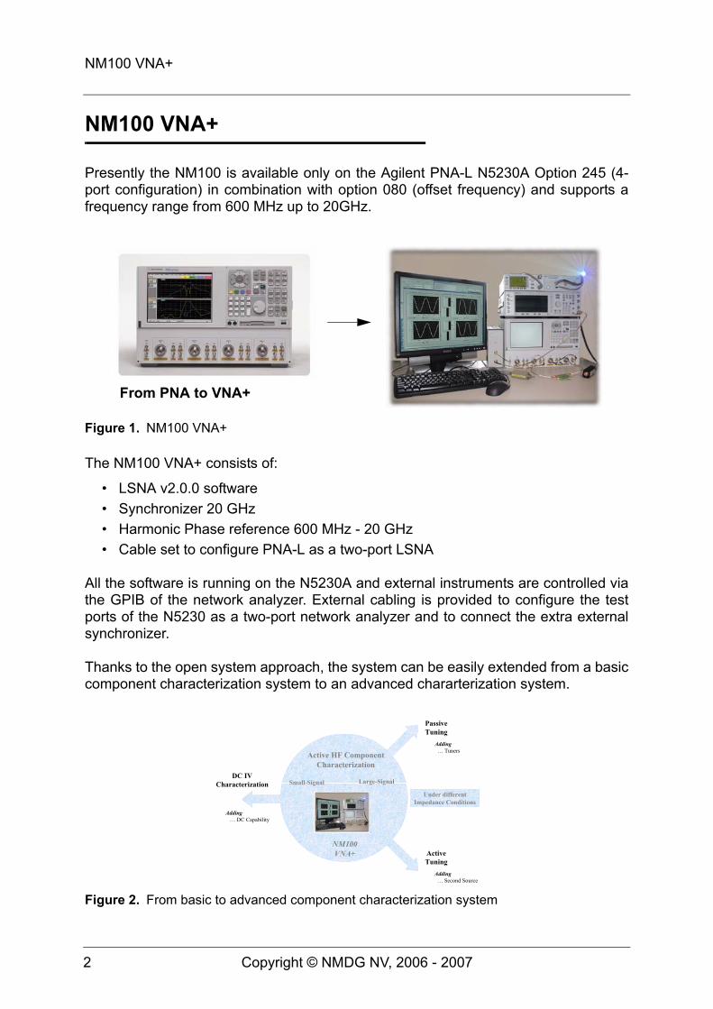
Presently the NM100 is available only on the Agilent PNA-L N5230A Option 245 (4-port configuration) in combination with option 080 (offset frequency) and supports afrequency range from 600 MHz up to 20GHz.
The NM100 VNA+ consists of:
• LSNA v2.0.0 software• Synchronizer 20 GHz• Harmonic Phase reference 600 MHz - 20 GHz• Cable set to configure PNA-L as a two-port LSNA
All the software is running on the N5230A and external instruments are controlled viathe GPIB of the network analyzer. External cabling is provided to configure the testports of the N5230 as a two-port network analyzer and to connect the extra externalsynchronizer.
Thanks to the open system approach, the system can be easily extended from a basiccomponent characterization system to an advanced chararterization system.
Figure 1. NM100 VNA+
Figure 2. From basic to advanced component characterization system
From PNA to VNA+
NM100VNA+
Active HF ComponentCharacterization
DC IVCharacterization Small-Signal Large-Signal
ActiveTuning
PassiveTuning
Under differentImpedance Conditions
Adding … DC Capability
Adding … Tuners
Adding … Second Source

The Block Diagram
Copyright © NMDG NV, 2006 - 2007 3
The Block Diagram
The NM100 VNA+ is an open, customizable system consisting of a core, customiza-ble and optional part, as shown in figure 3
The DUT interface represents the hardware required to connect the device under test(DUT) to the ports of the test set, provided by the proper configuration of the test portsof the N5230A. The DUT interface is completely determined by the type of DUT, whichcan either be connectorized, on wafer or in a fixture.
The test ports of the N530A are configured as a two-port test set to separate the inci-dent and reflected waves, resulting in four measurement channels. To provide biasand to measure the DC, external bias tees1 need to be added to the test ports. Thetest set terminates into an external port where a termination or one or more sourcesand/or tuners can be connected.
The N5230 is re-configured such that the four coupler outputs are connected to thefour mixer-based receiver channels of the N5230. The synchronizer provides thephase reference during large signal measurements, driven by the internal source ofthe Agilent PNA.
Figure 3. Core, customizable and optional components of the NM100 VNA+.
1. A bias tee could be required to block DC induced currents into the RHF input and output port.
DUT InterfaceConnectorsFixtureProbes...
External(Power)Test Set
PowerMeter
HarmonicPhase
Reference
CalibrationKit
Stimuli
Customizable
Core
Tuners
DC source
Volt-Current-
meter
Optional
Port 1 Port 2
Input
Synchronizer
Output
Termination

The Block Diagram
4 Copyright © NMDG NV, 2006 - 2007
For power applications an external test set can be supported in combination withswitchable attenuators going into the mixer - channel, when needed. The NM100VNA+ software supports this feature.
An external source, which can be limited to the frequency range of the application, isused to excite the device under test. This source needs to be locked to the 10 MHzreference coming from the PNA. All VNA+ software runs on the PNA and uses itsGPIB to control all required external instruments.
A regular vector network analyzer calibration kit, covering the full measurement band-width1, in combination with a power meter and harmonic phase reference are requiredto perform the absolute calibration. As with regular vector network analyzers, calibra-tion is necessary to perform accurate measurements. The calibrations are supportedby the NM100 software.
During the relative calibration the internal PNA synthesizer is used covering the fullmeasurement bandwidth1.
To provide different impedances to port 1 and port 2, it is possible to combine theVNA+ with passive and active tuners.
To measure the DC characteristics of the DUT simultaneously with the high frequencymeasurements, a combination of voltmeters or current meters at both ports isrequired. A more sophisticated solution is based on DC analyzers or DC force / sensesystems (Figure 4).
1. Harmonics need to be included in the frequency range
Figure 4. Typical configuration consisting of NM100 core and customizable parts.
Power Meter
Power Sensor
Harmonic Phase ReferenceAmplifier
Pulse Generator
Test Set
Test Board
Synchronizer
Source
PNA
External
Configuration

The NM100 Partitioning
Copyright © NMDG NV, 2006 - 2007 5
The NM100 Partitioning
In support of the open system architecture, the NM100 hardware can be subdivided inthree categories as shown in figure 3:
• core NM100 hardware• additional required NM100 hardware which is customizable• optional hardware
Core NM100
The core NM100 consists of
• an Agilent PNA-L N5230 Option 245 and Option 080 (offset frequency)1
• the NM100 synchronizer 600 MHz - 20 GHz• the NM100 Harmonic Phase Reference (HPR) 600 MHz - 20 GHz• the NM100 cable set to configure the test set
Additional required NM100 customizable hardware
The NM100 also requires1
• an external source to stimulate the device under test and to drive the HPR during calibration, minimal bandwidth 600 MHz - 1.2 GHz
• DUT interface hardware (connectors, fixture, probes, test port cables ...)• a power sensor and power meter (3.5 mm)• a calibration kit (3.5 mm)• a termination
Optional hardware
Typical optional hardware consists of1
• DC sources• DC sensing hardware• Tuners
1. Not included in NM100 VNA+

NM100 Specifications
6 Copyright © NMDG NV, 2006 - 2007
NM100 Specifications
Overall Specifications• Bandwidth: 600 MHz - 20 GHz• Power: typical 12 dBm• RF Frequency resolution: 1 Hz• Noise floor and dynamic range: depending on PNA specifications and selected
settings• Phase stability: ±3 degrees at 20 GHz
Harmonic Phase Reference Specifications• 100/120 Volt - 0.75 A (fuse 0.75 A - 250 Volt - fast)• 220/240 Volt - 0.4 A (fuse 0.4 A - 250 Volt - fast)• Drive frequency: 600 MHz - 1.2 GHz• Drive power: 11 dBm - 12 dBm• Pulse bandwidth: 20 GHz
• Phase repeatability of phasors: < +/- 1.75 degree up to 20 GHz1
• Max systematic phase error of phasors: < +/- 0.75 degree at 20 GHz1
Customizable and optional parts
Presently a limited number of instruments are supported. Other instruments can beadded on request.
Stimuli
1. Based on Agilents licensed Nose-2-Nose Calibration Technique
Freq Range Type20 and 40 GHz Agilent 836X0A/B20 and 40 GHz Agilent PSG CW E8247C opt 5X020 GHz Agilent PSG Vector E8267C opt 52020, 40 and 50 GHz Agilent PSG CW E8257D-5X040 GHz Agilent E8244A PSG50 GHz Agilent 83650B50 GHz Agilent PSG CW E8247C opt 540
+ 83555A mm-wave source module250 kHz - 2 GHz Agilent E4431B ESG-D Opt UND, 1E5, UN9

NM100 Specifications
Copyright © NMDG NV, 2006 - 2007 7
CAUTION The source must be able to drive the Harmonic Phase Referenceduring the calibration procedure. Check the required power levelsfor the Harmonic Phase Reference. Optionally an amplifier can beadded.
Power Sensor
Power Meter
Calibration Kit
250 kHz - 4 GHz Agilent E4433B ESG-D Opt UND, 1E5, UN9250 kHz - 4 GHz Agilent E4438C-602 ESG Vector Signal Genera-
tor20, 40 and 50 GHz Rhode & Schwarz SMR Series20, 40 and 50 GHz Anritsu MG3690A/B Series
Freq Range Type20 GHz Agilent 8485A50 GHz Agilent 8487A18 GHz Agilent N1921A40 GHz Agilent N1922A
TypeAgilent E4418BAgilent E4419BHP436HP438
Freq Range Type18 GHz Maury 2660S series Cal Kit 7mm20 GHz Maury 8050U series Cal Kit 3.5 mm50 GHz Maury 7950U series Cal Kit 2.4 mm6 / 18 GHz Agilent 85031B, 85050B/D Calibration Kit, 7 mm20 GHz Agilent 85052D Economy Mechanical Cal Kit 3.5 mm50 GHz Agilent 85056D Economy Mechanical Cal Kit 2.4 mm
Freq Range Type

NM100 Specifications
8 Copyright © NMDG NV, 2006 - 2007
DC Stimulus and Measurement
TypeAgilent 4142B Modular DC Source/MonitorAgilent 4156C Semiconductor Parameter AnalyzerAgilent E5270A 8-Slot Parametric Measurement MainframeAgilent E3631A Triple Output Programmable DC Power SupplyAgilent E3634A 200 W Power Supply, 25 V, 7 A or 50 V, 4 AAgilent 34401A Digital Multimeter, 6.5 DigitAgilent 662xx System Power SupplyKeithley 4200-SCS for DC Characterization
Software
Copyright © NMDG NV, 2006 - 2007 9
Software
Presently, the NM100 software is mainly focused on calibration support and measure-ments and less on providing different stimuli and performing sweepplans. Using thesupported DC, RF and microwave sources, already a limited set of stimuli can be con-trolled from the software. For the time being, there is no support for the customer toadd unsupported sources1 in a flexible way to the NM100 software. It is of course pos-sible to control these sources, either manually or programmatically with a tool ofchoice, and to perform and collect measurements using the NM100 software.
Graphical User Interface
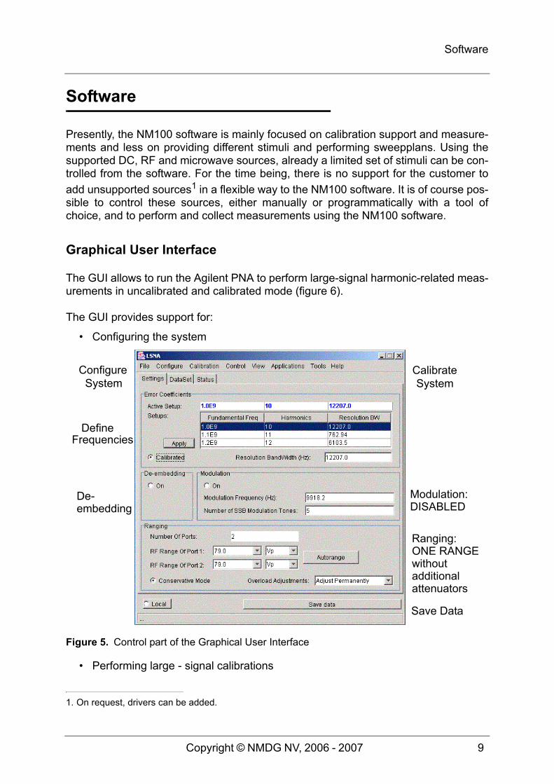
The GUI allows to run the Agilent PNA to perform large-signal harmonic-related meas-urements in uncalibrated and calibrated mode (figure 6).
The GUI provides support for:
• Configuring the system
• Performing large - signal calibrations
1. On request, drivers can be added.
Figure 5. Control part of the Graphical User Interface
ConfigureSystem
CalibrateSystem
De- Modulation:
Ranging:
Save Data
DefineFrequencies
DISABLED
ONE RANGEwithoutadditional
embedding
attenuators

Software
10 Copyright © NMDG NV, 2006 - 2007
• SOLT• LRRM• TRL• SOL (one - port relative calibration)
• Performing system - level calibrations• Characterization of test set losses to optimize power levels during calibration
• Setting up fundamental frequencies and harmonics• De-embedding• Ranging (when attenuators are present)• Displaying the measurements in different ways (figure 6)
• Voltage - Current at all ports• Incident - Reflected waves at all ports• Frequency and time domain• Dynamic source-line and load-line• Smith Chart at input and output
• Saving, retrieving and reviewing measurements in a raw format• Exporting measurements in CITIFile, table and CSV format (spreadsheets)
Scripting Language
For the advanced user, who wants to perform different types of processing on top ofthe measurements, powerful scripting capability is provided through the use of Mathe-
Figure 6. Time representation of voltage / current at input and output
V1 I1
V2 I2

Software
Copyright © NMDG NV, 2006 - 2007 11
matica™. In parallel with the GUI, the measurements can be accessed via a Mathe-matica™ notebook, where all the Mathematica™ processing capability is available forfurther processing and visualization.
The standard configuration includes the Mathematica™ software 5.2. The NM100software uses JLink and MathLink which is included with the Mathematica™ software.Optionally the customer can provide the Mathematica™ software taking the compati-bility requirements into account.
CAUTION Once Mathematica 5.1 or higher is installed, the LSNA sofwarev1.1 or higher cannot run without manual intervention with a previ-ous Mathematica version. Mathematica installation installs librariesunder Win system32 which causes incompatibilities starting from5.1.
Connectivity
Users, who want to control and to retrieve data from the NM100 VNA+, using the envi-ronment of their choice (e.g. LabVIEW™, MATLAB™, Agilent VEE, C etc.), can do soif their environment allows to connect to a DLL using a C header file that describes theinterface to the NM100. The user can then process and display the data in that envi-ronment (figure 7).
Mathematica Version JLink MathLink5.2 3.1.0 15 Preferred configuration
5.1.1 3.0.1 145.1.0 3.0.0 135.0.1 2.1.1 125.0.0 2.1.1 114.2 2.1.1 10
Table 1. Compatibility matrix for the Mathematica™ software

Software
12 Copyright © NMDG NV, 2006 - 2007
Figure 7. LabVIEW™ example using the C API.

Add-On Software Modules
Copyright © NMDG NV, 2006 - 2007 13
Add-On Software Modules
Additional software modules, not included in the standard NM100 software, are andwill become available. For most recent information, please visit http://www.nmdg.be.
ATS - LSNA connection
ATS, PC-based application software for automated RF Device Characterization Solu-tions and a product of Maury Microwave, does contain a connection to the NM100.This allows to display voltage and current or incident and reflected wave information indifferent formats for different impedance states within ATS and to execute powerfullsweepplans and save all measured data together.
Component Characterization in non-50 Ohm environment
The NM100 software in combination with the Maury tuner toolkit allows to performvoltage and current measurements in a non-50 Ohm environment. Due to the ope-ness of the system it is possible to perform also harmonic load-pull using active injec-tion. (figure 8).
Fundamental measurement-based behavioral modeling in a non-50 Ohm environment
Combining the NM100 VNA+ with the fundamental measurement-based behavioralmodeling toolkit, it is possible to create a model that describes the input and outputbehavior of the component at the fundamental. The model is easy to interprete and its
Figure 8. Active component characterization in a non-50 Ohm environment.
Tuner Control
Tuner De-embedding
Maury Tuner Toolkit

Add-On Software Modules
14 Copyright © NMDG NV, 2006 - 2007
boundary conditions of validity are also characterized. The toolkit consists out of twoGUIs. One graphical interface performs the necessary measurements and extractsthe model. A second GUI performs model verification, possibly on independant data.The verification compares the predicted reflected wave and transmitted wave withtheir measured counterparts for all different tuner states and input power states. Themodel can be imported into ADS.
Figure 9. Active component characterization in a non-50 Ohm environment.
Model data collection and extraction Model verification
Modelin ADS

Trademark information
Copyright © NMDG NV, 2006 - 2007 15
Trademark information
Agilent VEE and Agilent VEE Pro are registered trademarks of Agilent Technologies.Microsoft®, Windows®, Windows® 2000, Windows® XP and Microsoft® Visual C++are registered trademarks of Microsoft Corporation.LabVIEW is a registered trademark of National Instruments.Mathematica™ is a registered trademark of Wolfram Research.MATLAB is a registered trademark of The MathWorks.
All other brand and product names are trademarks or registered trademarks of theirrespective companies.
Agilent SICL1 is an I/O library developed by Agilent Technologies.
Contact Information
Product Information: http://www.nmdg.be/index_jump.html?goto=products_center
Support Information: http://www.nmdg.be/index_jump.html?goto=support/support_center
Printing history• Version 1.0.0. - May 2006• Version 1.0.1. - Dec 2007
1. Standard Instrument Control Library
For technical information on NM100 VNA+and sales information on MBBM with NM100
• NMDG NVC. Van Kerckhovenstraat 110B2880 BornemBelgium - EuropeTel: +32 3 890 46 12Fax: +32 3 890 46 29Email: [email protected]
For sales information on NM100 VNA+ andall information on ATS
• Maury Microwave2900 Inland Empire Blvd.OntarioCalifornia 91764 USATel: +1 (909) 987-4715Fax: +1 (909) 987-1112Email:Web: http://www.maurymw.com

Contact Information
16 Copyright © NMDG NV, 2006 - 2007
Related Documents


