arXiv:1102.2444v1 [astro-ph.CO] 11 Feb 2011 Large-scale shock-ionized and photo-ionized gas in M83: the impact of star formation Sungryong Hong 1 , Daniela Calzetti 1 , Michael A. Dopita 2 , William P. Blair 3 , Bradley C. Whitmore 4 , Bruce Balick 5 , Howard E. Bond 4 , Marcella Carollo 6 , Michael J. Disney 7 , Jay A. Frogel 8 , Donald Hall 9 , Jon A. Holtzman 10 , Randy A. Kimble 11 , Patrick J. McCarthy 12 , Robert W. O’Connell 13 , Francesco Paresce 14 , Abhijit Saha 15 , Joseph I. Silk 16 , John T. Trauger 17 , Alistair R. Walker 18 , Rogier A. Windhorst 19 , Erick T. Young 20 and Max Mutchler 4 1 Department of Astronomy, University of Massachusetts, Amherst, MA 01003 2 Research School of Astronomy & Astrophysics, The Australian National University, ACT 2611, Australia 3 Johns Hopkins University, Baltimore, MD, USA 4 Space Telescope Science Institute, Baltimore, MD 21218 5 Department of Astronomy, University of Washington, Seattle, WA 98195-1580 6 Department of Physics, ETH-Zurich, Zurich, 8093 Switzerland 7 School of Physics and Astronomy, Cardiff University, Cardiff CF24 3AA, United Kingdom 8 Association of Universities for Research in Astronomy, Washington, DC 20005 9 Institute for Astronomy, University of Hawaii, Honolulu, HI 96822 10 Department of Astronomy, New Mexico State University, Las Cruces, NM 88003 11 NASA–Goddard Space Flight Center, Greenbelt, MD 20771 12 Observatories of the Carnegie Institution of Washington, Pasadena, CA 91101-1292 13 Department of Astronomy, University of Virginia, Charlottesville, VA 22904-4325 14 Istituto di Astrofisica Spaziale e Fisica Cosmica, INAF, Via Gobetti 101, 40129 Bologna, Italy 15 National Optical Astronomy Observatories, Tucson, AZ 85726-6732 16 Department of Physics, University of Oxford, Oxford OX1 3PU, United Kingdom 17 NASA–Jet Propulsion Laboratory, Pasadena, CA 91109 18 Cerro Tololo Inter-American Observatory, La Serena, Chile 19 School of Earth and Space Exploration, Arizona State University, Tempe, AZ 85287-1404 20 NASA–Ames Research Center, Moffett Field, CA 94035

Welcome message from author
This document is posted to help you gain knowledge. Please leave a comment to let me know what you think about it! Share it to your friends and learn new things together.
Transcript

arX
iv:1
102.
2444
v1 [
astr
o-ph
.CO
] 1
1 Fe
b 20
11
Large-scale shock-ionized and photo-ionized gas in M83: the
impact of star formation
Sungryong Hong1, Daniela Calzetti1, Michael A. Dopita2, William P. Blair3,
Bradley C. Whitmore4, Bruce Balick5, Howard E. Bond4, Marcella Carollo6,
Michael J. Disney7, Jay A. Frogel8, Donald Hall9, Jon A. Holtzman10, Randy
A. Kimble11, Patrick J. McCarthy12, Robert W. O’Connell13, Francesco Paresce14,
Abhijit Saha15, Joseph I. Silk16, John T. Trauger17, Alistair R. Walker18, Rogier
A. Windhorst19, Erick T. Young 20 and Max Mutchler 4
1Department of Astronomy, University of Massachusetts, Amherst, MA 01003
2Research School of Astronomy & Astrophysics, The Australian National University, ACT 2611,
Australia
3Johns Hopkins University, Baltimore, MD, USA
4Space Telescope Science Institute, Baltimore, MD 21218
5Department of Astronomy, University of Washington, Seattle, WA 98195-1580
6Department of Physics, ETH-Zurich, Zurich, 8093 Switzerland
7School of Physics and Astronomy, Cardiff University, Cardiff CF24 3AA, United Kingdom
8Association of Universities for Research in Astronomy, Washington, DC 20005
9Institute for Astronomy, University of Hawaii, Honolulu, HI 96822
10Department of Astronomy, New Mexico State University, Las Cruces, NM 88003
11NASA–Goddard Space Flight Center, Greenbelt, MD 20771
12Observatories of the Carnegie Institution of Washington, Pasadena, CA 91101-1292
13Department of Astronomy, University of Virginia, Charlottesville, VA 22904-4325
14Istituto di Astrofisica Spaziale e Fisica Cosmica, INAF, Via Gobetti 101, 40129 Bologna, Italy
15National Optical Astronomy Observatories, Tucson, AZ 85726-6732
16Department of Physics, University of Oxford, Oxford OX1 3PU, United Kingdom
17NASA–Jet Propulsion Laboratory, Pasadena, CA 91109
18Cerro Tololo Inter-American Observatory, La Serena, Chile
19School of Earth and Space Exploration, Arizona State University, Tempe, AZ 85287-1404
20NASA–Ames Research Center, Moffett Field, CA 94035

– 2 –
ABSTRACT
We investigate the ionization structure of the nebular gas in
M83 using the line diagnostic diagram, [O III](5007A)/Hβ vs. [S
II](6716A+6731A)/Hα with the newly available narrowband images from
the Wide Field Camera 3 (WFC3) of the Hubble Space Telescope (HST).
We produce the diagnostic diagram on a pixel-by-pixel (0.2′′ × 0.2′′) ba-
sis and compare it with several photo- and shock-ionization models. We
select four regions from the center to the outer spiral arm and compare
them in the diagnostic diagram. For the photo-ionized gas, we observe a
gradual increase of the log([O III]/Hβ) ratios from the center to the spi-
ral arm, consistent with the metallicity gradient, as the H II regions go
from super solar abundance to roughly solar abundance from the center
out. Using the diagnostic diagram, we separate the photo-ionized from
the shock-ionized component of the gas. We find that the shock-ionized
Hα emission ranges from ∼2% to about 15–33% of the total, depending
on the separation criteria used. An interesting feature in the diagnostic
diagram is an horizontal distribution around log([O III]/Hβ) ≈ 0. This
feature is well fit by a shock-ionization model with 2.0 Z⊙ metallicity and
shock velocities in the range of 250 km/s to 350 km/s. A low velocity
shock component, < 200 km/s, is also detected, and is spatially located
at the boundary between the outer ring and the spiral arm. The low
velocity shock component can be due to : 1) supernova remnants located
nearby, 2) dynamical interaction between the outer ring and the spiral
arm, 3) abnormal line ratios from extreme local dust extinction. The
current data do not enable us to distinguish among those three possible
interpretations. Our main conclusion is that, even at the HST resolution,
the shocked gas represents a small fraction of the total ionized gas emis-
sion at less than 33% of the total. However, it accounts for virtually all
of the mechanical energy produced by the central starburst in M83.
Subject headings: galaxies: ISM – galaxies: interactions – galaxies: star-
burst – ISM: structure

– 3 –
1. Introduction
The feedback from star formation activity into the interstellar medium (ISM) is
a major, but still not fully characterized, mechanism that drives the formation and
evolution of galaxies. In starforming sites, the stellar winds and supernovae explo-
sions provide heat and momentum to the surrounding ISM changing its thermody-
namic properties and kinematics, and sometimes driving galactic scale superwinds
(Heckman et al. 1990, Martin et al. 2002). Such outflows from starforming regions
carry metals that can enrich the intergalactic medium (IGM) and suppress further
starforming activity (Oppenheimer & Dave 2006). Galactic scale outflows/winds
have been called upon to account for the mass-metallicity relation, to shape the lu-
minosity function of galaxies, especially at the faint end slope, and to account for the
kinematics of neutral gas in Damped Lyman Alpha systems (Tremonti et al. 2004,
Scannapieco et al. 2008, Hong et al. 2010).
Despite the importance of understanding stellar feedback in the context of galaxy
evolution, its observational constraints are still ill-defined. One of the largest un-
knowns is the “energy efficiency” of feedback, i.e. the fraction of a starburst’s
mechanical energy that is available to drive large-scale outflows. This is linked,
in the momentum-driven scenario, to the momentum transfer between the sources
(supernovae, stellar winds) and the surrounding ISM coupled with radiative-driven
pressure (Murray, Quataert, & Thompson 2005). On a more global scale, it is im-
portant to understand whether feedback and its efficiency can be linked to global
galactic parameters like specific SFR or the depth of the galactic potential well (i.e.
escape velocity). In this respect, local starburst galaxies are undoubtedly excellent
laboratories to study the feedback interaction in great details.
By investigating nearby galaxies, Martin (2005, 2006) suggests that a relation is
present between outflow speed and SFR, and that the kinetic energy contained in the
outflowing material is a few percent of the available mechanical energy from massive
star winds and supernovae. This implies that although the fraction of mechanical
energy deposited in the ISM is high, only a small fraction is available to drive the
outflow.
Here we concentrate on the starburst and H II regions hosted in the center of the
massive spiral galaxy M83, in order to investigate the interface between star forma-

– 4 –
tion and shocked gas not only in the powerful starburst, but also in the H II regions
hosted in the spiral arms of the galaxy. We perform a differential analysis of the
shocked gas surrounding the central starburst and the spiral arm H II regions, with
the goals of deriving the fraction of energy deposited in shocks and their morphology.
The line diagnostic diagram from nebular line emission, [O III](5007A)/Hβ vs.
[S II](6716A+6731A)(or [N II](6583A))/Hα ), has been used to study the starburst
or AGN activity in galaxies (Baldwin, Phillips, & Terlevich 1981, Kewley et al. 2001;
hereafter K01) and to investigate the ionized gas structure of ISM for resolved regions
(e.g. Calzetti et al. 2004; hereafter C04, Westmoquette et al. 2007). The HST’s
high angular resolution is crucial to study the ionized gas structure, especially for
shock-ionized gas, since, in general, the shocked gas is distributed in a thin layer,
easily confused with photo-ionization in low resolution ground-based observations.
We also need accurate ionization models since there is no strict boundary between
photo-ionized gas and shock-ionized gas in the diagnostic diagram. In this paper
we focus on the diagnostic diagram of M83 for the structure of ionized gas from the
newly available data obtained with the Wide Field Camera 3 (WFC3) onboard the
Hubble Space Telescope (HST).
The galaxy M83 is the nearest face-on grand-design spiral with Hubble type
SAB(s)c, at a distance of 4.47 Mpc (Kennicutt et al. 2008). There is an ongoing
central starburst possibly fueled by gas inflow along the main stellar bar connecting
the double circumnuclear rings found in the center (Trinchieri et al. 1985, Elmegreen
1998, C04). To study the non-photoionized gas (mostly shock-ionized gas driven by
stellar feedback) in the central region, C04 analyzed Wide Field Planetary Camera
2 (WFPC2) images on a pixel-by-pixel basis and compared the line diagnostics with
the photo-ionization model of K01 and shock-excited line ratios from Shull & Mc-
Kee (1979). To separate the shock-ionized gas from photo-ionized gas, C04 used
the “maximum starburst line” of K01. Because the “maximum starburst line” is a
conservative boundary for shocks, the shock measurement from those authors is a
lower limit to the actual fraction of shock emission. They find that the fraction of
shock-ionized Hα luminosity to photo-ionized luminosity is ∼ 3% in M83. Unlike
the dwarf galaxies, also analyzed in that paper, the geometrical morphology of shock
ionized gas in M83 was compact, rather than diffuse and shell-like, possibly due to
the deeper potential well in this more massive galaxy.
– 5 –
We provide, in this paper, the observed line diagnostics of the center and the
inner spiral arm of M83, and compare the data with theoretical expectations for the
line ratios. In section §2, we describe the data set and the reduction procedures,
including a detailed discussion of how to remove emission line contamination from
broad/medium band filters and [N II] contamination from the Hα line filter. Then we
present our results on the ionized gas structures and interpretations from theoretical
models in section §3. The summary follows in section §4.
2. Observations and Data Reduction
2.1. The WFC3 data set
Our WFC3 data are part of the WFC3 Science Oversight Committee (SOC)
Early Release Science (ERS) program (program ID11360, PI: Robert O’Connell).
The observed field, centered at R.A. = 13:37:04.42, DEC. = -29:51:28.0 (J2000),
covers the nuclear starburst region and the inner part of northeast spiral arm of M83.
Three or four (depending on the filter) spatially dithered exposures were used to re-
move cosmic rays through the MultiDrizzle software (Fruchter et al. 2009). We adopt
the PHOTFLAM values, available in URL:http://www.stsci.edu/hst/wfc3/phot zp lbn,
to convert instrumental data number(DN) to physical flux. We use the flux calibra-
tion value of F658N for F657N, for which a calibration is not available, since their
values for line emissions are similar within a few percent. The detailed information
about our data set is summarized in Table 1. Before we derive line ratio maps, we
rebin the images by 5× 5 pixels to reduce registration errors. The binned pixel size
is 0.2′′ or 4.3 pc in physical scale; i.e. smaller than the typical size of an H II region,
but comparable to the physical size of star clusters (Maiz-Apellaniz 2001).
2.2. Continuum Subtraction and [N II] Correction
The F487N and F502N narrowband filters each contain one line emission per
filter (Hβ and [O III](5007A) , respectively, redshifted to the recession velocity of
M83, 513 km/s). F657N and F673N contain multiple lines. In the case of F673N,
the lines are both [S II], from the 6716A and 6731A doublet, so we will simply

– 6 –
consider the sum of the two. In the F657N filter, the [N II] doublet at rest frame
6548A and 6584A is included in the filter bandpass in addition to Hα . Hence,
we have simpler filter throughput equations to obtain Hβ and [O III](5007A) fluxes
than Hα and [S II](6716A+6731A). As a trade-off, however, the stellar continuum
contained in the F487N and F502N filter is more affected by variations in the stellar
population mix and the local dust extinction than the redder lines, which means
their stellar continuum estimates have worse intrinsic accuracy than F657N and
F673N. Furthermore, the F555W filter, which we use as the broad-band continuum
filter to estimate the stellar contribution to F487N and F502N, is self-contaminated
by Hβ and [O III](5007A); we assume [O III](4959A) is negligible compared to the
two other lines. Therefore, we have to correct our filter fluxes for the following: (1)
contamination of Hβ and [O III](5007A) in the F555W filter, (2) [N II] contamination
in F657N.
To subtract the Hβ and [O III](5007A) lines from the F555W image, we apply
an iterative method which can be schematically described as:
Cont0 ← F555W
Hβi ← F487N − Conti[
O III]
i← F502N − Conti
Conti+1 ← F555W −Hβi − [O III]i
where each term represents the flux calibrated image for the denoted line emission and
filter. In this method, the starting value for the stellar continuum is the uncorrected
F555W, Cont0. With it, we obtain the first guesses to the Hβ and [O III](5007A)
emission line images by subtracting the stellar continuum from the respective narrow-
band filters. Then, by subtracting those first-guess line emissions from f555w, we can
derive the first order corrected continuum, Cont1. We can iterate the procedure until
the image converges. This procedure is similar in concept to the iterative procedure
applied in Mackenty et al. (2000) for NGC4214.
To quantify the improvement of the iterative method, we compare the corrected
F555W continuum after each iteration with the F547M image available in the HST
archive for the central region of M83, since F547M is a line emission-free filter. We
produce a residual image, F547M−µF555WF547M
, for each iteration step to investigate the
effect of each iteration on the F555W image. The parameter, µ, is chosen to minimize

– 7 –
the difference between the images in the two filters and is related to the scaling factor
for the stellar continuum subtraction from narrow-band images.
Figure 1 shows the pixel histogram of residual image for each iteration. The
uncorrected, 0th iterated, residual image shows a negative mean which indicates
excess flux from Hβ and [O III](5007A) in F555W. After the 1st iteration, the residual
images show a more symmetric pixel histogram than the uncorrected one showing
that the iterations remove the excess of line emission in F555W. The difference
between the uncorrected and the 1st corrected is appreciable especially in localized
regions, where flux changes up to 100% have been measured. Further iterations
do not change the F555W image appreciably. To quantify the difference for each
iteration step, we shows the mean (top) and the standard deviation (bottom) of the
residual images (left) and the corrected F555W (right) in Figure 2. We can observe
that 1, at most 2, iterations are sufficient to reach convergence. The converged
residual histogram in Figure 1 can be considered as an intrinsic difference between
the two filters. We take as final Hβ and [O III](5007A) emission line images those
resulting from the second-iterated F555W stellar continuum image.
The optimal scale factor to be applied to the broad band images for continuum
subtraction in the narrow band filters is found with the skewness transition method
(Hong et al. 2011; in prep). The skewness is defined as
skewness =1
N − 1
N∑
i=1
(xi −m
σ
)3
, where m is the mean, σ is the standard deviation, and N is the number of pixels
in a sample image. The skewness is generally used to measure asymmetry of a
statistical distribution. For symmetric functions, the value of the skewness is zero.
If a distribution has a long “right” tail, the skewness of the distribution is positive;
i.e. positive-skewed. For a distribution with a long “left” tail, the skewness is
negative; i.e. negative-skewed. For an image of blank sky, the pixel histogram is
generally gaussian (or poissonian). So the skewness is zero (or a small positive
number). Additional astronomical sources in a blank field, therefore, are weighing
on the right-hand side of pixel distribution which makes the distribution “positive-
skewed”. Since the continuum subtraction process removes stellar flux from the
narrow-band image, increasing the subtraction weight decreases the skewness value.
In a perfectly-subtracted narrow-band image, the skewness of the image pixels that

– 8 –
do not contain line emission is zero for a gaussian background. Our method attempts
to recover the optimal stellar continuum subtraction value by exploiting this property
of the skewness. Our simulations (Hong et al. 2011) show that the skewness function
shows a “transition” in correspondence of the optimal scaling factor for the stellar
continuum. So, by locating where this transition occurs in our HST images, we have
derived the optimal scaling factor for each narrow-band filter.
It should be noted that the use of a single scaling factor across each image
assumes that large color gradients (due to either changes in the stellar population
mix or in the dust extinction) are not present across the broad band filters. For
F657N and F673N, this assumption is mitigated by interpolating the two broad
band filters, F814W and the corrected F555W, to derive stellar continuum images
at the appropriate wavelength. Furthermore, except for a few regions in the nucleus
of M83, colors do not change dramatically across the F555W or F814W filter band
passes. We use a single continuum image interpolated at the intermediate wavelength
660 nm for both of F657N and F673N. Since the widths of the broad-band images
are larger than 100 nm, the interpolated image at 660nm can be used as continuum
for nearby emission lines located within a couple of 10 nm.
We produce two subtracted versions (optimized subtraction for the central region
and the spiral arm each) for [O III](5007A) and Hβ , since the bluer continuum
F555W suffers from more local deviation from color differences of background stellar
population than the redder filters. We take a single optimized subtraction for Hα and
[S II](6716A+6731A). We consider potential changes in color within the broad band
filters as a source of error in our photometry.
We assume that [S II](6716/6731) ≈ 1.2, since the ratios are between 1.0 and
1.4 in the ISM of M83 (Bresolin & Kennicutt 2002; hereafter BK02). For the [N
II] correction to Hα , we adopt the spectroscopic flux ratios, [N II]/Hα = 0.42 for
the spiral arm and 0.54 for the center from BK02. We, thus, generate two “Hα”
only maps; one with the [N II] subtraction optimized for the central region, and one
optimized for the spiral areas (Note that Hβ and [O III](5007A) have two optimized
versions due to different continuum subtraction, while for Hα due to different [N
II] correction). The [N II]/Hα ratios range from 0.40 to 0.47 in the spiral arm and
from 0.53 to 0. 56 in the center. The difference of the corrected Hα fluxes within
each of these ranges is less than 10 %, which is small enough to be negligible in our

– 9 –
analysis. C04 used the relation [N II] ≈ 2×[S II] too as an alternative method for
[N II] correction . The ratio [N II]/[S II] has been observed to be relatively constant,
since the ratio has less dependences on abundance and extreme variations in UV
radiation (Rand 1998, Kewley & Dopita 2002). C04 discusses the [N II] correction
in more details. Our adopted method produces results similar to those of C04. A
summary is given in Table 1 of the images or combination of images used for the
stellar continuum subtraction of each narrow-band image.
3. Results
Figure 3 shows the continuum subtracted images for Hα , Hβ , [O III](5007A),
and [S II](6716A+6731A) with 4σ cuts (see Table 1 for a list of the 1 σ flux levels). For
Hβ and [O III](5007A), the stellar continuum subtractions optimized for the central
regions are presented. We take 4σ cuts for all the narrowband images because of the
weakness of [O III](5007A) emission. Deeper rejection cuts would remove enough of
the [O III] emissions to remove most of the shock-ionized signal. As shown in Figure 3,
the surface brightness of [O III](5007A) is the major limiting factor to the number
of data points in the diagnostic diagram. To compensate for this limitation, we also
utilize the shock criteria from the [S II](6716A+6731A)/Hα ratio. This method is
less rigorous for shock separation than the diagnostic diagram but it can include
more area for our investigation, since [S II](6716A+6731A) is substantially brighter
than [O III](5007A) in M83.
We select four regions within the field of view of our narrow band images, which
are plotted as squares overlaid on the Hβ image in Figure 4. The four sub-regions are
labeled A1(red), A2(green), A3(blue), and A4(magenta). These regions are bright
enough in [O III](5007A) to enable analysis in the diagnostic diagram. They are
geometrically separated from each other and span a total galactocentric separation
of 2.5 kpc, which can probe the change of physical properties from the center to the
spiral arms.
In star forming regions, ultraviolet(UV) photons from stellar objects and hot
coronal gas heated by shocks are the major source of ionization of the surrounding
ISM. The total luminosity and hardness of the UV radiation are determined by a
combination of star forming history, metal abundance, stellar atmosphere model,

– 10 –
and stellar evolution tracks. We will refer to this as “photo-ionization”. The other
mechanism is collisional ionization that takes place in shocks caused by stellar winds
and supernovae. The stellar feedback energy from supernovae and stellar winds heats
up the surrounding gas and produces hot bubbles in star forming sites. Since the
temperature in hot bubbles is over a million degrees, the bubble is generally faint in
the optical, while it is bright in the X-ray. The over-pressure set up in the bubble by
the feedback energy pushes out the surrounding gas and produces shocks in the in-
terface between the bubble and the ambient ISM. When the shock becomes radiative
in the early adiabatic phase, the upstreaming radiation from the shock layers ionizes
the pre-shock gas. Unlike stellar emission, the radiation from shock layers is domi-
nated by free-free emission of hot coronal gas, so the properties of the shock emission
are different from those of the stellar emission. We term this as “shock-ionization”.
The diagnostic diagram, [O III](5007A)/Hβ vs. [S II](6716A+6731A)/Hα , has been
traditionally used to discern these two ionization mechanisms and many ionization
models provide predictions based on this diagnostic diagram for comparison with
observed data.
Figure 5 shows the distribution of the data points (0.2′′ pixels) from each of
the four subregions on the diagnostic diagram, together with theoretical tracks from
various ionization models of K01. Figure 6 shows the data points from all four
subregions on a single diagram. By comparing the data points with the theoretical
grids, we can infer many properties for the ionized gas in M83. In the following
sections we present in detail results about the photo-ionized gas, the shock-ionized
gas, and the implications of different choices for separating the two components.
3.1. Photo-ionized Gas
Figure 6 shows the overall distribution of the ionized gas in M83 on the diagnostic
diagram. The grey lines are photo-ionization models from K01 and the black lines
are shock-ionization models from Allen et al. (2008; hereafter, A08), which will be
described later in the section. The photo-ionized grids adopted from K01 are based on
the stellar population synthesis model STARBURST99 and the gas ionization code
MAPPINGS III (Leitherer et al 1999, Binette et al. 1985, Sutherland & Dopita 1993).
The spectral energy distributions (SED) generated from STARBURST99 provide the

– 11 –
photo-ionization source and the MAPPINGS III code calculates the ionization states
and the line emission fluxes. From those, we can derive the theoretical line ratios
for photo-ionization. The plotted photo-ionization grids in Figure 6 are calculated
assuming a constant star formation history, Geneva stellar evolution tracks (Schaller
et al. 1992), and Lejeune stellar atmosphere models (Lejeune et al. 1997); see K01
for more details. While the assumption of constant star formation may not strictly
apply to the spiral area H II regions, it is a good representation of star formation in
the starburst nucleus of M83 (C04). The case of instantaneous burst models will be
discussed later in this section.
The selected ISM densities are 10 and 350 cm−3 which we take as representative
of the ISM conditions in M83, and the metallicities are chosen to be 1.0Z⊙ and 2.0Z⊙,
the range observed in the galaxy (BK02). The dimensionless ionization parameter,
q, defined as the ratio of mean photon density to mean atom density, ranges from
5.0× 10⁶ to 3.0× 10⁸ for each model. The line called “Photoionization Limit” in the
legend of Figure 6 is the conservative track termed “Maximum Starburst Line” in
K01. Above and to the right of this track, line ratios can not be explained by photo-
ionization. Since the outputs of STARBURST99 depend on a variety of inputs, such
as stellar evolution tracks, stellar atmosphere models, and star formation history,
we can use our theoretical grids primarily for qualitative comparisons rather than a
quantitative analysis.
One of the interesting results from the photo-ionized zone in Figure 6 is that
the observed [O III]/Hβ ratios at low [S II]/Hα values span the range covered
by the photo-ionization models for different values of the metallicity; higher [O
III](5007A)/Hβ ratios correspond to lower metallicity in the models. Generally
[O III](5007A)/Hβ ratios are not enough to determine the metallicity of a region
(Kewley & Dopita 2002), except in the range between solar abundance to super-solar
abundance. The red “P” box in Figure 6 is a photo-ionized region, where the [O
III](5007A)/Hβ line ratio is sensitive to metallicity. We re-project the pixels of the
P box on the line emission images and select small subregions, labeled as PA1, PA2,
PA31, PA32, and PA4, as shown in Figure 4, to investigate the relation between
the observed [O III](5007A)/Hβ ratio and metallicity. Those regions are bright in
each emission line and geometrically clustered in compact regions. The sizes of the
regions are close to the size of the spectroscopic aperture used in BK02. In addition,
PA1 and PA4 correspond to the regions, “A” and “9” in BK02, respectively.

– 12 –
In the P box, we can also observe a weak rank-ordering of the [O III]/Hβ ratios
according to the regions they belong to : A1 > A2 > A3 ≈ A4. Interestingly,
that is the exact order of distance from the center. This relation between the [O
III]/Hβ ratios and the distance from the center appears consistent with the metallicity
gradient from the center to the spiral arms in M83.
To verify this, we present the observed relation between oxygen abundance and
[O III]/Hβ ratios in Figure 7. The black (named “MG”) and the grey (named “E”)
points are borrowed from the spectroscopic results of BK02. The names “MG” and
“E” indicate the different oxygen abundance calibrations from McGaugh (1991) and
Edmunds (1989). The figure shows the direct correlation between [O III]/Hβ ratio
and oxygen abundance. To compare our data with those from BK02, we convert the
distance of each region to the oxygen abundance using the relation between distance
and oxygen abundance in BK02 and overplot them in Figure 7. The horizontal error
bar is due to the physical size of each region and the vertical error bar represents
the standard deviation of the line ratio distribution among the pixels within each
region. Since our resolution is much higher than the spectroscopic aperture, 0.2′′ for
each pixel, the line ratios are distributed in a broad range for the A1, ..., A4 regions,
as well as the PA1, ..., PA4 regions. The overall trend is consistent with the same
metallicity trend as BK02. So the metallicity gradient from center to spiral arm
appears to cause the spread in [O III]/Hβ values in the “photo-ionized” area of the
diagnostic diagram of Figure 6 at low [S II]/Hα values.
To investigate in detail the physical properties of the photo-ionized gas in M83,
we present additional photo-ionization models in Figure 8. The two top panels
show two different star formation history models; constant star formation (left) and
instantaneous burst (right) from K01. The constant star formation model assumes
durations larger than 8 Myr, when the dynamical balance between the stellar births
and deaths is set up for UV radiation. The instantaneous burst model is the case for
zero age stellar population, which is the extreme end in star formation history. Thus,
these two models bracket a range of star formation histories for our regions. Both
show similar metallicity dependence; lower [O III]/Hβ ratio for higher metallicity.
The constant star formation model with 2.0 Z⊙ marks the lower envelope to the
photo-ionized data, thus fully including all pixels in A1.
Dopita et al. (2006; hereafter DP06) introduced models for time-evolving H II

– 13 –
region. While K01 treats the ionization parameter as an independent parameter,
DP06 calculates the ionization parameter as a function of the age of the stellar
cluster. The DP06 models are based on a one dimensional spherical geometry for the
evolving H II region. The radius and pressure evolution are derived from the works
of Castor et al. (1975) and Oey & Clarke (1997, 1998):
R =( 250
308π
)1/5L1/5mechρ
−1/50 t3/5
P =7
(3850π)2/5L2/5mechρ
3/50 t−4/5
where Lmech is the instantaneous mechanical luminosity from the cluster, ρ0 is the
ambient ISM density, and t is the time. DP06 found that the ionization parameter
in their models depends on the mass of the stellar cluster and the pressure of the
surrounding ISM, and it scales as q ∝ M1/5cl P
−1/50 , where Mcl is the initial mass of
the stellar cluster and P0 is the initial ISM pressure surrounding the stellar cluster.
Hence, the ratio, R= log10[(Mcl/M⊙)/(P0/k)] where P0/k is measured in cgs units
(cm−3 K), uniquely determines the time-evolving track of the ionization parameter
as an initial condition (see DP06 for more details). The middle panels in Figure 8
show the DP06 models for two different metallicities, 1.0 Z⊙(left) and 2.0 Z⊙(right).
We also compare these models with re-binned data (see bottom panels of Figure 8)
to investigate the impact of the binning size on our results. In all cases analyzed,
we find that an evolving HII region scenario at constant metallicity does not fully
reproduce the observed trend in the data, although each covers a portion of the locus
occupied by the data points. The full range of the data can be covered by varying
the metal abundance by more than a factor 10, which we consider unlikely given the
relative small size of our regions (≈970 pc). At this stage, the best model to fit the
photo–ionized gas appears to be the continuous starburst scenario.
The instantaneous models assume zero-aged stellar population and DP06 models
track the age effect on such instantaneous models using the evolution dynamics
described by the above equations. These two models are hard to reconcile with
observations if the stellar population contains a mix of stellar clusters with various
ages or if the ionization parameter can not be derived from the equations above.
Those equations are exact only in the case of an isolated H II region. For a starburst
region, the photo-ionized gas is diffuse and distributed on a large scale plus the region
itself is the complex superposition of many H II regions. For this case, the ionization
– 14 –
parameter is better treated as an independent parameter rather than derived from
an isotropically expanding sphere. The age distribution of stellar clusters in M83
approximately follows a power-law distribution (Chandar et al. 2010): there are
many clusters formed within 107 yrs, and the power-law extends by a few million
years. Therefore, the combination of multiple stellar population ages and complex
geometry of the photo-ionized gas can be the reasons why the continuous models fit
the observation more closely.
3.2. Transition from Photo-ionization to Shock-ionization
The adopted separation criteria for the shock and photo-ionized gas need to be
discussed in this kind of study, because there is no objective separation between the
two phases in the diagnostic diagram. The maximum starburst line, or “Photoioniza-
tion Limit” in Figure 6, is a conservative limit (see K01 and Kauffmann et al. 2003),
above and to the right of which line ratios can not be produced by photo-ionization.
This provides a lower limit to the amount of shock-ionized gas; in Table 2, we list,
for this discriminant (called M1), the Hα luminosity, fraction of the total luminosity,
and fraction of the total area occupied by shocks. A second discriminant can be
provided by photo-ionization models matched to the solar-to-super-solar metallicity
of M83. If we choose, conservatively, the N350Z1.0 model of Figure 6, the fraction of
Hα luminosity and area occupied by shocks increases dramatically (M2 in Table 2).
In this case, even the H II regions located along the spiral arm outside the central re-
gion show evidence for a shock component, albeit at the level of ≈ 1%. Conversely, in
the central starburst, about 15% of the total Hα luminosity is due to shocks. A third
discriminant (called M3) can be provided by shock-ionization models. Data points
will be considered shocks if they lie within the region covered by shock+precursor
models. The M3 criterion is the most generous, among the three discussed so far, in
including pixels from each region among the ‘shocks’, it will provide a robust upper
limit to our shock estimates. The shock Hα luminosity in the spiral arm regions is
now 4% (A3) or less of the total Hα luminosity, still is not a significant amount. A
much larger fraction, about 33% of the total, is derived for the central starburst, the
most generous estimate among all criteria.
Finally, as the low surface brightness of [O III](5007A) is the major limit-

– 15 –
ing factor for our diagnostics, we attempt to use the single line ratio criterion, [S
II]/Hα > −0.5, to overcome this limitation (M4 in Table 2). This is another gener-
ous criterion for discriminating shocks from photo-ionization, like the M3 criterion,
although it provides a less accurate separation than the diagnostic diagram involving
the [OIII] line; however, it does not suffer from the limitations produced by faint or
undetected [O III](5007A). Figure 9 shows the theoretical relation between normal-
ized Hα flux and [S II]/Hα ratio from the continuous starburst model of K01 and the
shock+precursor model of A08. In this figure, we define three regions: (1) the shock
zone, log([S II]/Hα )> −0.5, (2) the mixing zone, −1 < log([S II]/Hα ) < −0.5, and
(3) the photo-ionization zone, log([S II]/Hα ) < −1. Our single-ratio diagnostics,
log([S II]/Hα ) > −0.5, thus contains contributions from photo-ionized gas at low
surface brightness. We consider this “contamination” acceptable, in view of the fact
that we recover all signal from shocks. Figure 10 shows the observed relation between
the dust extinction corrected Hα flux and the [S II]/Hα ratios for A1, A2, A3, and
A4. The comparison of Figures 9 and 10 suggests that shocks are present in all four
regions analyzed.
In Table 2, the SFR is calculated from the photo-ionized gas only; i.e. (total
Hα luminosity - shock Hα luminosity), corrected for the effects of extinction using
the WFC3 Pβ(λ1.282µm) image (Liu et al. 2011, in prep). The SFR density is
calculated by dividing the SFR by the area of the photo-ionized pixels. Figure 11
shows the spatial distribution of the ionized gas from Table 2 according to each
shock separation criterion, M1, M2, M3, and M4; the Hα images (4 σ cut) covering
the regions, A1, A2, A3, and A4, are shown in the first column together with the
locations of photo-ionized gas (red) and shock-ionized gas (blue) with the shock
criteria of M1(the second column), M2(the third column), M3(the fourth column),
and M4(the fifth column).
In the spiral arm (regions A2, A3, A4), the shock gas from the “Maximum
Starburst Line” criteria(M1) is negligible. In the other criteria(M2, M3, and M4),
the luminosity ratios and the area ratios are 4% or less. Figure 10 also shows that
most of the log([S II]/Hα) values in A2, A3, and A4, are less than -1, so located in
the photo-ionization zone. Therefore, feedback from star formation is very low in the
spiral arm of M83 perhaps owing to the youth of the H II regions we detect. Shocks
remain a small or negligible component in the outer H II regions.

– 16 –
For the central starburst, the SFR is 2.7 times larger than the previous study
of C04 due to a better Hα filter coverage in the present study (the WFPC2 narrow-
band filter used in the C04 study placed the redshifted Hα on the red shoulder of the
filter). In addition, the Pβ/Hα extinction map we use probes larger dust extinction
values than the Hα/Hβ extinction map (Liu et al. 2011; in prep). The SFR density
of A1 is 3 times larger than the values of A2, A3, and A4. For the conservative
shock estimate(M1), the luminosity ratio and the area ratio of A1 are consistent
with the previous study of C04 when we consider the range of values for different
[N II] corrections of the Hα filter. In this conservative criterion, a few percents of
the Hα luminosity comes from shock gas. The area occupied by the shock gas is
larger than the luminosity contribution, consistent with the fact that the shock gas
has lower Hα brightness but is distributed more diffusely than the photo-ionized
gas. For the other criteria (M2, M3, and M4), the shock Hα luminosities can reach
15% to 33% of the total luminosity. The covering areas of shocks are also larger
totaling 28% to 53% of the total area. The M3 and M4 criteria are generous, and
may misclassify as shocks some regions that could actually contain mostly photo-
ionized gas; we thus expect the shock luminosity and area can be overestimated for
M3 and M4. We conclude that the acceptable values are 15% for the Hα luminosity
and 30% for the areal coverage of shocks in the center of M83. When comparing our
15% fraction of shocked gas in the central starburst of M83 with expectations for
the mechanical energy output from the starburst itself (4% to 9%, columns 4 and 8
of Table 6 in C04), we conclude that virtually all of the available mechanical energy
from massive star winds and supernovae is radiated. This is in agreement with the
findings of Martin (2006), who conclude that only a few percent of the mechanical
energy from star formation is available as kinetic energy to drive the ISM.
3.3. Shock-ionized Gas
In this section, we compare our data with shock-ionization models and investi-
gate the properties of the shock-ionized gas. The shock-ionization model of A08 uses
the ionizing radiation field from hot radiative shock layers dominated by free-free
emission and the MAPPINGS III code to calculate the gas ionization state and the
intensity of the emission lines. The emission from shocks consists of two components;
the shock layer (postshock component) and the precursor (preshock component). The

– 17 –
shock layer is the cooling zone of the radiative shock and the precursor is the region
ionized by the upstreaming photons from the cooling zone. Since free-free emission
is dominant in shock layers, the ionizing radiation field from shocks is mainly deter-
mined by the shock velocity and the preshock gas density (see A08 for more details).
So for a given metallicity and pre–shock gas density, the shock velocity is the main
parameter determining the line ratios in the diagnostics. The main branch of the
shock grids labeled with “B=1.0E-4” in Figure 6 shows the line ratios for shock ve-
locities from 100 km/s to 900km/s, with a fixed ISM magnetic field of 10−4µG . The
magnetic field in the ISM plays an important role in determining the post-shock gas
density: higher ISM magnetic fields correspond to lower post-shock densities, with
major effects on the ionization parameter of the post-shock gas component. Hence,
the magnetic field is the second main parameter in shock models. The side branches
from the selected shock velocities, 100, 150, ..., 500 km/s, show the effect of changing
the magnetic fields from 10−4µG to 10µG. The metallicity of the model is 2Z⊙ and
the preshock gas density is 1 cm−3.
Two peculiar features can be identified in Figure 6, in the region dominated by
shock-excitation. One is a series of pixels in a roughly horizontal sequence, around
log([O III]/Hβ ) ∼ 0, which seem to be consistent with the horizontal feature of the
shock+precursor model from A08. This horizontal distribution of shock-ionized gas
is a unique feature when compared with other solar and sub-solar abundant galaxies
such as NGC3077, NGC4214, and NGC5253 in C04, which have the shock-ionized
gas near or outside of the “Maximum Starburst Line”. A part of the feature is
marked by a box labeled ‘S2’ in the figure, where it is outside of the photo-ionization
locus. So, the ‘S2’ region can be considered as a shock-ionized region with high shock
velocities (> 300 km/s) according to the shock models. The other peculiar feature is
a vertical plume located at log([O III]/Hβ ) > 0.2 and −1 < log([S II]/Hα ) < −0.5,
where some low velocity shocks are likely to be present based on the shock models.
This region, also marked by a box in Figure 6, is labeled ‘S1’. Both regions belong to
the nuclear region A1, where the most active star formation in the galaxy is taking
place.
The horizontal feature around S2 in the diagnostic diagram is highlighted in
Figure 12, where the data are compared with: the shock+precursor models from
A08 (top-left panel), and the precursor and the shock shown as separate curves, also
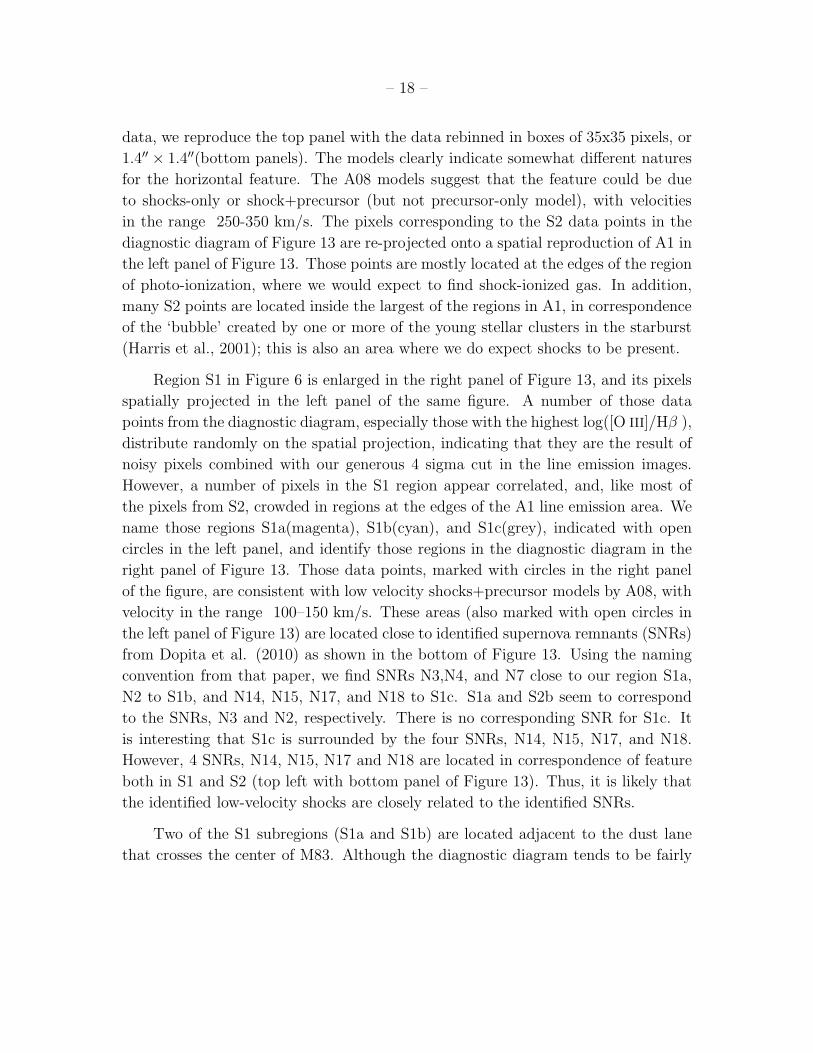
from A08 (top-right panel). To assess again the impact of spatial sampling on our
– 18 –
data, we reproduce the top panel with the data rebinned in boxes of 35x35 pixels, or
1.4′′ × 1.4′′(bottom panels). The models clearly indicate somewhat different natures
for the horizontal feature. The A08 models suggest that the feature could be due
to shocks-only or shock+precursor (but not precursor-only model), with velocities
in the range 250-350 km/s. The pixels corresponding to the S2 data points in the
diagnostic diagram of Figure 13 are re-projected onto a spatial reproduction of A1 in
the left panel of Figure 13. Those points are mostly located at the edges of the region
of photo-ionization, where we would expect to find shock-ionized gas. In addition,
many S2 points are located inside the largest of the regions in A1, in correspondence
of the ‘bubble’ created by one or more of the young stellar clusters in the starburst
(Harris et al., 2001); this is also an area where we do expect shocks to be present.
Region S1 in Figure 6 is enlarged in the right panel of Figure 13, and its pixels
spatially projected in the left panel of the same figure. A number of those data
points from the diagnostic diagram, especially those with the highest log([O III]/Hβ ),
distribute randomly on the spatial projection, indicating that they are the result of
noisy pixels combined with our generous 4 sigma cut in the line emission images.
However, a number of pixels in the S1 region appear correlated, and, like most of
the pixels from S2, crowded in regions at the edges of the A1 line emission area. We
name those regions S1a(magenta), S1b(cyan), and S1c(grey), indicated with open
circles in the left panel, and identify those regions in the diagnostic diagram in the
right panel of Figure 13. Those data points, marked with circles in the right panel
of the figure, are consistent with low velocity shocks+precursor models by A08, with
velocity in the range 100–150 km/s. These areas (also marked with open circles in
the left panel of Figure 13) are located close to identified supernova remnants (SNRs)
from Dopita et al. (2010) as shown in the bottom of Figure 13. Using the naming
convention from that paper, we find SNRs N3,N4, and N7 close to our region S1a,
N2 to S1b, and N14, N15, N17, and N18 to S1c. S1a and S2b seem to correspond
to the SNRs, N3 and N2, respectively. There is no corresponding SNR for S1c. It
is interesting that S1c is surrounded by the four SNRs, N14, N15, N17, and N18.
However, 4 SNRs, N14, N15, N17 and N18 are located in correspondence of feature
both in S1 and S2 (top left with bottom panel of Figure 13). Thus, it is likely that
the identified low-velocity shocks are closely related to the identified SNRs.
Two of the S1 subregions (S1a and S1b) are located adjacent to the dust lane
that crosses the center of M83. Although the diagnostic diagram tends to be fairly

– 19 –
unaffected by dust extinction, the large dust column densities found in dust lanes
may have an impact on the line ratios. We can not eliminate this possibility with
the data in hand. Finally, dynamical interactions may play a role in the creation
of low velocity shocks. S1a and S1c are located at the junction points of the spiral
arms to the central outer ring, while S1b is in–between the spiral arm and the outer
ring. The interaction between those morphological features could be at the basis of
the observed shocks.
The width of the precursor of a shock front is generally larger than our binned
pixel size(∼ 4.3pc), while photo-ionization equilibrium can be achieved well within
the size. For the shock model of A08 with solar abundance, 1 cm−3 preshock gas
density, 200 km/s shock velocity, and 3.2 µG magnetic field, the length of preshock
ionized zone is 40 pc, while the length of postshock cooling zone is less than 4 pc.
Even though the postshock zone (shock layer) can be small enough to fit in our
bin size, the preshock component is much larger than our bin scale. This means
that , unlike the photo-ionization model, the shock-ionization model needs to be
applied carefully when we compare it with the data. For instance, if a pixel line-
of-sight passes through both of precursor and shock front, the pixel line ratio is
meaningful when compared with the shock+precursor grids. If a pixel only covers
a part of the precursor region or shock front, the comparison has to be made with
shock-only or precursor-only models. When we consider the complicated geometry
through observed line-of-sights, it is hard to determine which light-of-sight is for
shock-only, precursor-only or shock+precursor. Therefore, we may need to make a
geometrical block enough to cover both of shock and precursor, but excluding photo-
ionized gas, and sum up the whole line flux in the block in order to compare it
with the shock+precursor model. So basically shock-ionization models may need, in
principle, to be compared on a large-scale basis than what done so far. However, as
shown in the bottom panels of both Figures 8 and 12, rebinned to pixel sizes of 1.4′′
(∼30 pc), the quantitative distribution of the data points on the diagnostic diagram
does not change, implying that our smaller pixel scale is adequate to average out
effects of spatial variations in shocks.

– 20 –
4. Summary
We have presented emission line diagnostic diagrams for the central ∼4 kpc of
the nearby starburst galaxy M83, using the newly available WFC3 images in order
to investigate the properties and morphology of both the photo-ionized and shock-
ionized gas on a pixel-by-pixel basis. Here is the summary of our results:
1. A comparison of the data with a number of photo- and shock-ionization
models show that the best fit for the data of the central starburst region (A1 in our
convention) is given by a combination of the Z=2 Z⊙ photo–ionization models of K01
and the shock+precursor models of A08.
2. Regions at increasing galactocentric distance show an increasing [O III]/Hβ ratio
for the photo–ionized gas, consistent with the presence of a metallicity gradient in
the galaxy.
3. Changing the discriminating ‘line’ between shocks and photo–ionized gas has
major implications for the fraction of ionized gas that can be attributed to shocks.
The Maximum Starburst Line of K01 (the most conservative criterion for identifying
shocks; See Kauffmann et al. 2003) produces fractions of a few percent, in agreement
with previous results (e.g., C04). Adopting a metallicity–dependent criterion, the
fraction of shock–ionized Hα luminosity increases to about 15%, and is in any case
no larger than about 33% in the starburst center, while shocks are always negligible
in the spiral area H II regions. At the 15% level, this requires that virtually all the
mechanical energy produced in the starburst center is radiated away in the shocks.
4. We find three regions dominated by low velocity shocks. All three are located
at the edges of the central starburst, and can have one of three possible origins: a)
can be the result of feedback from SNRs located near each component; b) can be
due to the dynamical interaction between the center and the spiral arm; c) could be
the result of the extreme local dust extinction. Discriminating among these three
scenarios will require additional more sophisticated observations.
We are grateful to an anonymous referee for comments that have improved
this paper. This paper is based on observations taken with the NASA/ESA Hubble
Space Telescope obtained at the Space Telescope Scinece Institute, which is operated
by AURA, Inc., under NASA contract NAS5-26555. It uses Early Release Science

– 21 –
observations made by the WFC3 Science Oversight Committee. We are grateful to
the Director of STScI for awarding Directors Discretionary time for this program.

– 22 –
REFERENCES
Allen, M.G., et al. 2008, ApJS 178, 20 (A08)
Baldwin, J. A., Philips, M. M., & Terlevich, R. 1981, PASP, 93, 5
Binette, L., Dopita, M. A., & Tuohy, I. R. 1985, ApJ, 297, 476
Bresolin, F., & Kennicutt, R.C. 2002, ApJ, 572, 838
Calzetti, D., Harris, J., Gallagher, J. S., et al. 2004, AJ, 127, 1405 (C04)
Chandar, R., et al. 2010, ApJ, 719, 966
Castor, J., McCray, R., & Weaver, R. 1975, ApJ, 200, L107
Dopita, M.A. et al. 2006, ApJS, 167, 177 (DP06)
Dopita, M.A. et al. 2010, ApJ, 710, 964
Edmunds, M.G. 1989, in Evolutionary Phenomena in Galaxies, ed. J.E. Beckman &
B.E.J. Pagel (Cambridge: Cambridge Univ. Press), 356
Elmegreen, D.M., Chromey, F.R., & Warren, A. R. 1998, AJ, 116, 2834
Fruchter, A. et al. 2009, ”The MultiDrizzle Handbook”, version 3.0, (Baltimore,
STScI)
Liu, G., et al. in prep.
Harris, J., et al., 2001, AJ, 122, 3046
Heckman, T.M., Armus, L., & Miley, G.K. 1990, ApJS, 74, 833
Hong, S., et al. 2010, arXiv:1008.4242v2
Hong, S., et al. 2011 in prep.
Kauffmann, G., et al. 2003, MNRAS, 346, 1055
Kennicutt, R. C. et al. 2008, ApJS, 178, 247
Kewley, L. J., et al. 2001, ApJ, 556, 121(K01)
– 23 –
Kewley, L.J., & Dopita, M.A. 2002, ApJS, 142, 35
Leitherer, C., & Heckman, T. M. 1995, ApJS, 96, 9
Mackenty, J. W., et al. 2000, AJ, 120, 3007
Oey, M. S., & Clarke, C. J. 1997, MNRAS, 289, 570
———. 1998, AJ, 115, 1543
Leitherer, C., et al. 1999, ApJS, 123, 3
Lejeune, Th., Cuisinier, F., & Buser, R. 1997, A&AS, 125, 229
Maiz-Apellaniz, J. 2001, ApJ, 563, 151
Martin, C.L., Kobulnicky, H.A., & Heckman, T.M. 2002, ApJ, 574, 663
Martin, C.L. 2005, ApJ, 621, 227
Martin, C.L. 2006, ApJ, 647, 222
McGaugh, S.S. 1991, ApJ, 380, 140
Murray, N., Quataert, E., Thompson, T. A. 2005, ApJ, 618, 569
Oppenheimer, B.D, & Dave, R.2006, MNRAS, 373, 1265
Rand, R.J. 1998, ApJ, 501, 137
Rich, J. A. et al. 2010, ApJ, 721, 505
Tremonti, C.A., et al. 2004, ApJ, 613, 898
Trinchieri, G., Fabbiano, G., & Paulumbo, G.G.C., 1985, ApJ, 290, 96
Scannapieco, C., Tissera, P.B., White, S.D.M., & Springel, V. 2005, MNRAS, 364,
552
Schaller, G., Schaerer, D., Meynet, G., & Maeder, A. 1992, A&AS, 96, 269
Shull, J.M., & McKee, C.F. 1979, ApJ, 227, 131

– 24 –
Sutherland, R. S., & Dopita, M. A. 1993, ApJS, 88, 253
Westmoquette, M.S., Smith, L.J., Gallagher, J.S., & Exter,K.M., 2007, MNRAS,
381, 913
This preprint was prepared with the AAS LATEX macros v5.0.

– 25 –
0
0.02
0.04
0.06
0.08
-0.2 -0.1 0 0.1 0.2
NO
RM
AL
IZE
D P
IXE
L C
OU
NT
S
(F547M - µ F555W) / F547M
0th
1st
2nd
3rd
Fig. 1.— The pixel histograms of the residual images, F547M−µF555WF547M
, for each iter-
ation of the emission line subtraction algorithm from F555W. The parameter, µ, is
chosen to minimize the difference between the images in F547M and F555W using
the same method used for the continuum subtraction in the narrow band images.
The histograms show the overall difference between the images in the F547M filter
and in the corrected F555W filter at each iteration. The original, 0th, histogram is
skewed towards a negative mean value, where higher order iterations produce more
symmetric, and similar to each other, histograms. The overall excess of negative
pixels in the 0th image is the amount of line emission contamination in F555W. The
improvement of the 1st corrected image from the original one is large, and further
iterations do not improve on that by an appreciable amount .

– 26 –
-0.015
-0.010
-0.005
ME
AN
F547M - µ F555W
F547M
4.4
4.5
4.6
F555W
0.048
0.050
0.052
0th 1st 2nd 3rd
STA
ND
AR
D D
EV
IAT
ION
ITERATIONS
F547M - µ F555W
F547M
0th 1st 2nd 3rd
7.5
7.7
7.9
ITERATIONS
F555W
Fig. 2.— The mean (top) and the standard deviation (bottom) of the residual
images (left) , F547M−µF555WF547M
, and the corrected F555W images (right) as a function
of the number of iterations. As shown in Figure 1, the 1st corrected image shows a
measurable improvement, while further iterations do not change the image quality
in a measurable fashion. So the second iteration is enough for the final derivation of
the Hβ and [O III](5007A) line emission images.

– 27 –
Hα Hβ
[OIII] [SII]
Fig. 3.— The 4 σ images for Hα , Hβ , [O III](5007A), and [S II](6716A+6731A).
The images of Hβ and [O III](5007A) shown here are the versions where the stellar-
continuum subtraction has been optimized for the nuclear region. The field shown
here is the entire field of view of WFC3/UVIS.

– 28 –
6′′ = 130 pc
45 ′′ = 970 pc
Fig. 4.— The Hβ image (4σ) and the locations of regions, A1, A2, A3, and A4. The
smaller boxes, PA1,.., and PA4 are selected from the “P” box in Figure 6. PA1 and
PA4 correspond to the regions “A” and “9”, in BK02, respectively.

– 29 –
-1
0
1
log(
[O I
II]/
Hβ)
A1
-1
0
1
-2 -1 0
log(
[O I
II]/
Hβ)
log([S II]/Hα)
A3
A2
-1 0
log([S II]/Hα)
A4
Fig. 5.— The line diagnostic diagram, [O III](5007A)/Hβ vs. [S
II](6716A+6731A)/Hα , for each area delineated by a large box in Figure 4, A1(top-
left), A2(top-right), A3(bottom-left), and A4(bottom-right). The data are color-
coded according to the colors of the box they belong to Figure 4. Sample theoretical
models for photo-ionized gas (grey lines, K01) and shock-ionized gas (black squares
joined by lines, A08) are also shown in each panel. A detailed description of the
models is given in the text and in Figure 6.

– 30 –
-1.5
-1
-0.5
0
0.5
1
1.5
-2 -1.5 -1 -0.5 0 0.5
log(
[O I
II]/
Hβ)
log([S II]/Hα)
q = 3e8
q = 5e6
Photo-ionized Zone
Shock-ionized Zone
Vs=100km/sVs=500km/s
S1
S2
P
A1A2A3A4
N10Z1.0N350Z1.0N10Z2.0
N350Z2.0Photoionization Limit
Vs = 100 km/sVs = 150 km/sVs = 200 km/sVs = 250 km/sVs = 300 km/sVs = 350 km/sVs = 400 km/sVs = 450 km/sVs = 500 km/s
B = 1.0E-4
Fig. 6.— The line diagnostic diagram, [O III](5007A)/Hβ vs. [S
II](6716A+6731A)/Hα , for each area of Figure 4, A1(red), A2(green), A3(blue),
and A4(magenta). The grey lines represent photo-ionization models of constant star
formation from K01. The “Photoionization Limit” listed in the legend to the right of
the figure is the conservative limit for extreme photo-ionization introduced in K01.
The model name N10Z1.0 represents the case of solar metallicity and an ISM density
of 10 cm−3, and is plotted for the range 5E+6 to 3E+8 for the dimensionless ion-
ization parameter q. Others follow the same naming convention and are plotted for
the same range of ionization parameters (grey lines). The black lines represent the
shock-ionization model with twice solar metal abundance from A08 (Shock + Pre-
cursor model). The “B=1.0E-4” line shows the line ratios for various shock velocities
(100, 125, 150, ... , 900km/s at 25 km/s intervals; black squares) with the 10−4µG
magnetic field. The side branches from the “B=1.0E-4” line of selected shock veloc-
ities (100,150, ... , 500 km/s; side branches from black squares) show the effect of
increasing magnetic fields from 10−4 to 10 µG. The boxes, “P”,“S1” and ”S2”, are
described in the sections, 3.1 (P) and 3.3 (S1 and S2) respectivily.

– 31 –
-1
-0.5
0
8.9 9 9.1 9.2 9.3
log(
OII
I/H
β)
12 + log(O/H)
A1A2A3A4PA
MGE
Fig. 7.— The ratio of [O III]/Hβ vs. the oxygen abundance. The black and grey
points are reproduced from Table 3 in BK02. The name “MG” and “E” indicate the
different oxygen abundance calibrations from McGaugh (1991) and Edmunds (1989).
The smaller regions, PAs, have the angular sizes around 5′′ which is somewhat larger
than, but still comparable to, the spectroscopic slit size 2′′ in BK02. The mean ratios
for A1, A2, A3, and A4, are slightly larger than the spectroscopic results. For the
subregions, PA1,..., and PA4, the mean values are consistent with BK02. The vertical
errorbars of the PA regions, the standard deviations of the line ratio distributions
for PA regions, are as large as their parent regions, A1, ... , and A4, so we omit
the vertical error bars for the PA regions. Since the PA regions are chosen for their
brightness and compactness relative to A1,..., and A4, the higher [O III]/Hβ ratios
in A1,..., and A4, can be due to gas that is too faint and diffuse for spectroscopic
study.

– 32 –
-1
0
1lo
g([O
III
]/H
β)Continuous Starburst Models
N10Z2.0
N350Z2.0
N10Z1.0
N350Z1.0
-1
0
1
log(
[O I
II]/
Hβ)
Time Evolving HII Region 1.0 Z⊙
R=+2,0,-2,-4,-6R=+2
R=-6
1.0 Myr
1.5 Myr
-1
0
1
-2 -1
log(
[O I
II]/
Hβ)
log([S II]/Hα)
Time Evolving HII Region 1.0 Z⊙
R=+2,0,-2,-4,-6R=+2
R=-6
1.0 Myr
1.5 Myr
Instantaneous Starburst Models
N10Z2.0
N350Z2.0
N10Z1.0N350Z1.0
Time Evolving HII Region 2.0 Z⊙
R=+2,0,-2,-4,-6
R=+2
R=-6
0.5 Myr
1.0 Myr
-1 0
log([S II]/Hα)
Time Evolving HII Region 2.0 Z⊙
R=+2,0,-2,-4,-6
R=+2
R=-6
0.5 Myr
1.0 Myr
Fig. 8.— Top: The continuous starburst models (left) and the instantaneous star-
burst models (right) of K01. Middle: The time evolution tracks of H II regions from
Dopita et al. (2006); solar abundance (left) and twice solar abundance (right). Bot-
tom: The rebinned data points by 7 × 7 pixel square (35 × 35 bin for the original
WFC3 pixels) corresponding to 1.4′′. The rebinned resolution is the spatial resolution
of Rich et al. (2010) and a generally achievable one in ground-based observation.

– 33 –
-2.5
-2
-1.5
-1
-0.5
0
0.5
-5 -4 -3 -2 -1 0 1
log(
[S I
I]/H
α)
log(Hα)[ergs s-1 cm-2]
q = 3e8
q = 5e6
400km/s
100km/s
K01 N10Z1.0K01 N10Z2.0
K01 N350Z1.0K01 N350Z2.0
A08 Z1.0 V100km/sA08 Z1.0 V150km/sA08 Z1.0 V200km/sA08 Z1.0 V300km/sA08 Z1.0 V400km/sA08 Z2.0 V100km/sA08 Z2.0 V150km/sA08 Z2.0 V200km/sA08 Z2.0 V300km/sA08 Z2.0 V400km/s
Fig. 9.— The log([S II]/Hα) vs. the normalized Hα flux from K01 and A08 models.
From the log ([S II]/Hα) ratios, we can define three zones; 1) shock-ionized zone:
log([S II]/Hα) > −0.5; 2) mixing zone: −1 < log([S II]/Hα) < −0.5; 3) photo-
ionized zone: log([S II]/Hα) < −1.

– 34 –
-2
-1
0
1
log(
[S I
I]/H
α)
A1
-2
-1
0
1
10-16 10-15 10-14 10-13
log(
[S I
I]/H
α)
log(Hα)[ergs s-1 cm-2]
A3
A2
10-16 10-15 10-14 10-13
log(Hα)[ergs s-1 cm-2]
A4
Fig. 10.— The [S II]/Hα ratio vs. the dust extinction corrected Hα flux for the pixels
in A1, A2, A3, and A4. The vertical and oblique cuts to the left and bottom-left of
the data points are our 4 σ detection limits. The 1 σ limit for each line emission is
summarized in Table 1. Most data points in A2, A3, and A4, have the ratios lower
than -1; the photo-ionized zone in Figure 9. Similarly to what found in the diagnostic
diagram of Figure 5, the regions in the spiral arm have little shock-ionized gas. In A1,
most data points reside in the mixing zone, −1 < [S II](6716A+6731A)/Hα < −0.5.

– 35 –
A1
A2
A3
A4
M1 M2 M3 M4Hα
Fig. 11.— The Hα images (4 σ detection limit) covering the regions, A1, A2, A3,
and A4 (first column), the locations of photo-ionized gas (red) and shock-ionized
gas (blue) with the shock criteria M1(second column), M2(third column), M3(forth
column), and M4(fifth column). In the M4 criterion, some faint diffuse photo-ionized
gas with low ionization parameter is counted as shock-ionized gas, thus, producing
contamination in the shocked gas and causing an overestimate of both the luminosity
and area of the shock component.

– 36 –
0
1
log(
[O I
II]/
Hβ)
Shock+Precursor(A08)
S2 S2
Precursor(A08)
Shock(A08)
0
1
-1 0
log(
[O I
II]/
Hβ)
log([S II]/Hα)
Shock+Precursor(A08)
S2
-1 0
log([S II]/Hα)
S2
Precursor(A08)
Shock(A08)
Fig. 12.— Top: The Shock+Precursor model of A08 (left) and the Shock-Only model
(blue) with the Precursor-Only model (green) of A08 (right). Bottom: The rebinned
points by 35×35 pixels square corresponding to 1.4′′ with the shock+precursor model
of A08 (left) and the Shock-Only model (blue) with the Precursor-Only model (green)
of A08 (right).

– 37 –
-10"
0
10"
0 10" 20"
A1S1S2
S1aS1bS1c
-1 0
0
1
log([
O I
II]/
Hβ)
log([S II]/Hα)
S1
S2
A1S1aS1bS1c
Vs = 100 km/sVs = 125 km/sVs = 150 km/sVs = 175 km/s
B = 1.0E-4
S1c
S1b
S1a-10''
20''10''
10''
0
0
N19
N18 N17
N16
N15
N14
N13
N12
N11
N10
N09
N08
N07
N06
N05
N04N03
N02
N01
Fig. 13.— Top left : The physical locations of the “S1”(green point) and the
“S2”(blue point) in A1. Many S1 pixels seem to be distributed randomly. Those can
be noises because of 4σ cuts. But some pixels show geometrical correlation and we
locate and recolor the spots as S1a(magenta), S1b(cyan), and S1c(grey) with open
circles. Top right : The identifications of S1a, S1b, and S1c in the diagnostic dia-
gram. The S1a, S1b, and S1c follow the low velocity shock grids well. Bottom: The
positions of SNRs in Dopital et al. (2010) in red circles and our low velocity shock
components, S1a, S1b, and S1c, in green crosses.

– 38 –
Table 1. WFC3 Observation (Program ID 11360)
Filter Exposure (sec) Date Obs. (2009) Continuuma 1 σ Limit b
F487N (Hβ) 3× 900 Aug 25 F555W 4.3× 10⁻¹⁸
F502N ([O III](5007A)) 3× 828 Aug 26 F555W 4.6× 10⁻¹⁸
F657N (Hα) 4× 371 Aug 25 0.58 F555W + 0.42 F814W 2.8× 10⁻¹⁷
F673N ([S II](6716A+6731A)) 2× 600, 650 Aug 20 0.58 F555W + 0.42 F814W 5.8× 10⁻¹⁸
F555W 3× 401 Aug 26 ... ...
F814W 3× 401 Aug 26 ... ...
aThe continuum images used for subtracting stellar continuums from narrowband images. The interpolated
wavelength is 6600A(660 nm) for both of [S II] and Hα . Because the filter widths of the broad band images are
much larger than the wavelength separation between our chosen wavelength (660nm) and each of the red emission
lines, our rough single interpolation is acceptable with typical errors of less than 5%.
bThe 1 σ detection limit for each emission-line, in units of ergs s−1 cm−2 per bin, where a bin is 5× 5 pixels (or
0.2′′ × 0.2′′), after subtraction of the stellar continuum.

– 39 –
Table 2. Measured and derived quantities
Shock Separation Criteria Region LHα,tota LHα,sh
b SFRc SFR densityd LHα,sh/LHα,tote Ash/Atot
f
(Separation Model Name) (erg s−1) (erg s−1) (M⊙ yr−1) (M⊙ yr−1 kpc−2)
Maximum Starburst Line A1 1.07 × 1041 1.71 × 1039 0.831 8.30 0.016 (0.030, 0.012) 0.029 (0.16, 0.07)
(M1) A2 1.36 × 1039 0.0 0.011 2.55 0.0 0.0
A3 1.53 × 1039 0.0 0.012 2.70 0.0 0.0
A4 1.04 × 1039 0.0 0.008 2.18 0.0 0.0
N350 continuous Z1.0 Line A1 1.07 × 1041 1.57 × 1040 0.720 9.77 0.147 0.284
(M2) A2 1.36 × 1039 1.56 × 1037 0.011 2.59 0.012 0.026
A3 1.53 × 1039 1.61 × 1037 0.012 2.83 0.010 0.058
A4 1.04 × 1039 8.01 × 1036 0.008 2.29 0.008 0.054
Shock Locus A1 1.07 × 1041 3.49 × 1040 0.569 12.0 0.326 0.539
(M3) A2 1.36 × 1039 3.47 × 1036 0.011 2.60 0.003 0.022
A3 1.53 × 1039 6.43 × 1037 0.012 3.00 0.042 0.140
A4 1.04 × 1039 1.36 × 1037 0.008 2.36 0.013 0.089
log([S II]/Hα) > −0.5 A1 2.09 × 1041 4.13 × 1040 1.324 5.64 0.198 0.500
(M4) A2 1.08 × 1040 3.94 × 1037 0.085 1.56 0.004 0.031
A3 1.53 × 1040 5.25 × 1037 0.121 1.69 0.003 0.032
A4 6.31 × 1039 5.13 × 1037 0.049 1.24 0.008 0.054
aTotal Hα luminosity in each region.
bHα luminosity of shocked gas.
cStar formation rates from the Hα flux of the photo-ionized gas corrected for extinction (See section 3.2).
dSFR divided by the pixel areas (Average SFR density per pixel area).
eFraction of the total Hα luminosity associated with shock-ionized gas.
fFraction of the Hα area occupied by shock-ionized gas. The values in parenthesis of ‘e’ and ‘f’ columns are from C04 and correspond to different [N II]
corrections. See C04 for more details.
Related Documents